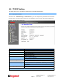
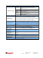
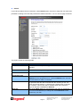
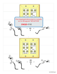
1
4 Port Gigabit Enhanced Router/Switch (P/N DA1054) User’s Guide 1308150 REV. D Page i 301 Fulling Mill Road, Suite G ©Copyright 2012 by Legrand, Middletown, PA 17057 Inc All Rights Reserved. (800)-321-2343 www.onqlegrand.com FCC Certifications This equipment generates and uses radio frequency energy and if not installed and used properly, that is, in strict accordance with the instructions provided with the equipment, may cause interference to radio and TV communication. The equipment has been tested and found to comply with the limits for a Class B digital device in accordance with the specifications in Subpart B of Part 15 of FCC rules, which are designed to provide reasonable protection against such interference in a residential installation. However, there is no guarantee that interference will not occur in a particular installation. If you suspect this equipment is causing interference, turn your Router/Switch on and off while your radio or TV is showing interference, if the interference disappears when you turn your Router/Switch off and reappears when you turn it back on, there is interference being caused by the Router/Switch. You can try to correct the interference by one or more of the following measures: Reorient the receiving radio or TV antenna where this may be done safely. To the extent possible, relocate the radio, TV or other receiver away from the Router/Switch. Plug the Router/Switch into a different power outlet so that the Router/Switch and the receiver are on different branch circuits. If necessary, you should consult the place of purchase or an experienced radio/television technician for additional suggestions. CE Mark Warning This is a class B device, In a domestic environment, this product may cause radio interference, in which case the user may be required to take adequate measures. All trademarks and brand names are the property of their respective proprietors. Specifications are subject to change without prior notification. Page ii 301 Fulling Mill Road, Suite G ©Copyright 2012 by Legrand, Middletown, PA 17057 Inc All Rights Reserved. (800)-321-2343 www.onqlegrand.com TABLE OF CONTENTS 1.0 Introduction ................................................................................................................ 4 1.1 Features .................................................................................................................. 5 1.2 Minimum Requirements .......................................................................................... 6 1.3 Detailed Physical Description.................................................................................. 7 1.4 Installation ............................................................................................................... 8 1.5 Initial Configuration ............................................................................................... 10 2.0 Network Settings ...................................................................................................... 13 2.1 Quick Setup .......................................................................................................... 13 2.2 Setup Wizard ........................................................................................................ 13 2.3 Network Operation Mode ...................................................................................... 17 2.3.1 TCP/IP Settings ............................................................................................ 18 2.3.1.1 LAN Interface Setup ............................................................................. 18 2.3.1.2 WAN Interface Setup ............................................................................ 19 DHCP Client ............................................................................................... 20 Static IP....................................................................................................... 21 PPPoE ........................................................................................................ 22 Page iii 301 Fulling Mill Road, Suite G ©Copyright 2012 by Legrand, Middletown, PA 17057 Inc All Rights Reserved. (800)-321-2343 www.onqlegrand.com 1.0 Introduction The Legrand 4 Port Gigabit Enhanced Router/Switch (P/N DA1054) is a flexible hardware configurable switch/router product designed to be used as a router with an integrated 4-port Gigabit rd Ethernet switch, or as a 5-port Gigabit Ethernet switch for use with a 3 party external router. It is the perfect solution to connect a small group of PCs to a high-speed broadband Internet connection (see Figure 1). Up to 253 users can have high-speed Internet access simultaneously via one single IP address (Internet account) of the Cable/xDSL modem. With its built in NAT technology, this product also serves as an Internet firewall, protecting your network from being accessed by outside users. All incoming data packets are monitored and filtered. The Router can also be configured with Client Filtering, to filter internal users’ access to the Internet. The built-in 4-port Gigabit Ethernet Switch lets users plug the network cable into the device without buying additional Hub/Switch. DA1054 To Network Figure 1 NOTE: Legrand Unity systems need to be upgraded to firmware release 2.2.x or later to properly function with this router. Page 4 301 Fulling Mill Road, Suite G ©Copyright 2012 by Legrand, Middletown, PA 17057 Inc All Rights Reserved. (800)-321-2343 www.onqlegrand.com 1.1 Features Internet Access Features All Gigabit Ports Support. Auto-negotiation, auto MDI/MDI-X Ethernet ports. DA1054 eliminates most cabling inconvenience. One WAN port, 10/100/1000Base-T is connected to your DSL or Cable modem. The other 4 LAN ports, 10/100/1000Base-T are used to connect to local LAN. Shared Internet Access. All users on the LAN can access the Internet through the DA1054 using only a single external IP Address. The local (invalid) IP Addresses are hidden from external sources. This process is called NAT (Network Address Translation). Fixed, PPPoE, Dynamic, and Direct Connection Support. Various WAN connections are supported by DA1054. Advanced Internet Functions Internet Communication Applications. DA1054 supports Internet communication applications, such as interactive Games, Telephony, and Conferencing applications, which are often difficult to use when behind a Firewall Special Internet Applications. Using non-standard connections or port numbers are normally blocked by the Firewall. The ability to define and allow such applications is provided, to enable such applications to be used normally. Virtual Servers Support. This feature allows Internet users to access Internet servers on your LAN. The required setup is quick and easy. DMZ. Support. DA1054 can translate public IP addresses to private IP address to allow unrestricted 2-way communication with Servers or individual users on the Internet. This provides the most flexibility to run programs, which are incompatible with Firewalls. URL Filter. Keyword based URL Filter to block access to undesirable Web sites by LAN users. Firewall. It supports Stateful Packet Inspection firewall for DoS (Denial of Service) attacks. Dynamic DNS Support. When used with the Virtual Servers feature, allows users to connect to Servers on your LAN using a Domain Name, even if you have a dynamic IP address which changes every time you connect. VPN Pass through Support. PCs with VPN (Virtual Private Networking) software using PPTP, L2TP and IPSec are transparently supported - no configuration is required. Access Control .Using the Access Control feature, you can assign LAN users to different groups, and determine which Internet services are available to each group. Password protected Configuration. Optional password protection is provided to prevent unauthorized users from modifying the configuration data and settings. LAN Features DHCP Server Support. Dynamic Host Configuration Protocol provides a dynamic IP address to PCs and other devices upon request. DA1054 can act as a DHCP Server for devices on your local LAN and WLAN. PC database. LAN users can be added manually or discovered automatically by DA1054, through this built-in user database, administrators are able to have a centralized networking management. Routing. LANs containing one or more segments are supported via RIP1 (Routing Information Protocol) support and built-in static routing table. Configuration & Management Easy Setup. Built-In configuration wizard helps users to complete network installation in a very short time via standard Internet browsers such as Microsoft Internet Explorer, Firefox, Chrome…etc. Remote Management. DA1054 can be managed from any PC on LAN or via Internet anywhere around the world. UPnP Support. UPnP (Universal Plug and Play) allows automatic discovery and configuration of the DA1054. UPnP is by supported by Windows ME, XP, or later. Logs. It provides system log and security log, and log can be saved or mail to a specific account. Configuration File Upload/Download. Save (download) the configuration data from the Broadband Router to your PC and restore (upload) a previously-saved configuration file to the Broadband Router. Page 5 301 Fulling Mill Road, Suite G ©Copyright 2012 by Legrand, Middletown, PA 17057 Inc All Rights Reserved. (800)-321-2343 www.onqlegrand.com 1.2 Minimum Requirements One External xDSL, FIOS, or Cable modem with an Ethernet port (RJ-45) Network Interface Card (NIC) for each Personal Computer (PC) PCs with a Web-Browser (Internet Explorer 7.0 or higher, or Firefox 3.6 or higher) Page 6 301 Fulling Mill Road, Suite G ©Copyright 2012 by Legrand, Middletown, PA 17057 Inc All Rights Reserved. (800)-321-2343 www.onqlegrand.com 1.3 Detailed Physical Description Router/Switch Module Connection Area Figure 2 shows the Router/Switch connection area including: DC Input connector – from power supply WAN (Internet) Port – 8 position RJ-45 jack (to Cable or DSL or FIOS modem) Local Switch Ports – 8 position RJ-45 jacks (from outlets in rooms) Routing Switch – Disconnects router from 4-port switch when an external router is used th and converts WAN port to 5 switch port (power re-cycle required). Reset Button - A button press cycles the power, while a ten (10) second press and hold resets the Router/Switch unit to the factory default settings. This clears all user settings, including User Name, Password, IP Address, and Subnet Mask. NOTE: Refer to Section IV Configuration for instructions on re-configuring the Router/Switch. Routing Switch STATUS Reset Button Local Switch Ports WAN Port Figure 2 DC Input Router/Switch Status LEDs next to each RJ45 connector(see Figure 2) Power – On solid green when power is supplied. Link/Act and 1000 Local Port and WAN Port LEDs Link/Act – On solid green indicates functional LAN or WAN link through the port with the attached device. Off means no LAN or WAN connection. 1000 – On solid green indicates port is operating at 1000 Mbps. Off indicates otherwise. Page 7 301 Fulling Mill Road, Suite G ©Copyright 2012 by Legrand, Middletown, PA 17057 Inc All Rights Reserved. (800)-321-2343 www.onqlegrand.com 1.4 Installation The DA1054 4 Port Router/Switch is best installed during new construction in two steps; at “roughin” after the Electricians are done, but prior to drywall being installed, and at “trim-out” after the drywall is installed and painted. These steps are detailed below: A. “Rough-in” steps: 1. A single dedicated Cat 5e/6 should be run in the walls from the structured wiring enclosure location in the home where the 4 Port Router/Switch will be installed to each outlet location in the rooms where Internet service is required (leave extra cable at both ends). NOTE: Run Cat 5e/6 cable at least 12” from electrical cabling (preferably in a separate stud cavity) and cross electrical cables at a 90° angle. Use loose Velcro-style cable ties for bundling. If stapling is required, use specialty staples to avoid compressing the cable. 2. At the selected outlet locations, a single gang box or low voltage bracket should be installed, with the extra Cat 5e/6 cable in the box, or attached in such a way that it may be fished out after the drywall is installed. B. “Trim-out” steps: 1. The Cat 5e/6 that was secured at each of the outlets should be pulled out and terminated with a 110 punchdown tool on an RJ45 insert and attached to a wallplate, which is then installed in the single gang box or low voltage bracket. 2. In the structured wiring enclosure the Cat 5e from the outlets may be terminated with a 110 punchdown tool onto a Legrand Network Interface Module or with RJ-45 plugs, using a tool such as our EZ RJ45 Modular Plug Hand Toll (P/N 364555-01) for direct connection to the DA1054 4 Port Gigabit Router/Switch. 3. The 4 Port Gigabit Router/Switch is installed in the structured wiring enclosure by slipping the tabs into the square holes, and using the push pin in a round hole to secure the router. 4. If the outlet cables were punched down at a Network Interface Module, Cat 5e/6 patch cables (available separately) are then connected from the 6 Port Network Interface Module to the input ports on the 4-Port Gigabit Router/Switch. 5. An additional Cat 5e/6 patch cable is then connected from the network (WAN) port of the 4 Port Gigabit Router/Switch to the Cable Modem or DSL Modem housed in the structured wiring enclosure and make sure the routing switch is in the “On” position. Page 8 301 Fulling Mill Road, Suite G ©Copyright 2012 by Legrand, Middletown, PA 17057 Inc All Rights Reserved. (800)-321-2343 www.onqlegrand.com 6. The 4 Port Gigabit Router/Switch is powered with an AC to DC adapter which also needs to be plugged in to an AC source. 7. Follow the steps in the next two sections for configuring the router. NOTE: Use proper tools and standard TIA 568A rules to prep and terminate the Cat 5e/6 cable, such as a Cat 5 Cable Stripper, an RJ45 Crimp Tool and a 110 Punchdown Tool. Page 9 301 Fulling Mill Road, Suite G ©Copyright 2012 by Legrand, Middletown, PA 17057 Inc All Rights Reserved. (800)-321-2343 www.onqlegrand.com 1.5 Initial Configuration The DA1054 4 Port Gigabit Router/Switch is typically configured in one of two ways; (1) From a portable PC connected through one of the Local Switch Ports on the Router/Switch Module in the enclosure, or (2) From a PC in one of the rooms of the house, connected through an outlet in the room to the enclosure where it is patched to (or directly connected to) one of the Local Switch Ports (see Figure 3). In either case, the PC must have an Ethernet Network Interface Card to communicate with the Router/Switch. Figure 3 A. Configuring a Network Interface Card to talk to the Router/Switch NOTE: The steps below assume that your PC’s network interface card is set to DHCP, or in other words, to obtain IP addressing automatically. The steps also assume that the 4 Port Gigabit Router/Switch is set to its default settings and that all the cables previously discussed are properly connected. It is also possible to perform these steps by configuring your computer (with installed Ethernet Network Interface Card) to talk to the Router/Switch on its specific IP subnetwork (192.168.40.xxx). The Router/Switch’s default IP address in that subnetwork is 192.168.40.254, so your PC’s Ethernet Card can be temporarily assigned an IP address, (like 192.168.40.10), on that same subnetwork to talk to and configure the Router/Switch. Giving the PC a specific IP address is also called assigning it a Static IP address, as compared to a Dynamic IP address that is typically assigned by a service provider when your PC’s network interface card is configured for Dynamic Host Configuration Protocol (DHCP). Page 10 301 Fulling Mill Road, Suite G ©Copyright 2012 by Legrand, Middletown, PA 17057 Inc All Rights Reserved. (800)-321-2343 www.onqlegrand.com NOTE: Before doing any PC IP Address re-configuration, make sure you first write down all of the current IP settings. XP users can set “last known useable configuration” under System Accessories before re-configuring. B. Logging on to the Router/Switch 1. With your PC connected to one of the local ports on the Router/Switch and its front panel routing switch in the “On” position, open a browser and enter the Router/Switch’s default IP address (192.168.40.254), and click “Go” (see Figure 4) to get the login page. Figure 4 2. To logon, enter “admin” for the user name and password and just click OK (see Figure 5). 192.168.40.254 admin ***** Figure 5 3. Figure 6 shows the System Status screen that you will see once you have logged on. By clicking on the “Setup Wizard” selection in the upper left corner, the Setup Wizard will lead you step-by-step through the initial configuration of the Router. NOTE: You can also manually configure the Router/Switch by clicking on a function listed on the left of the page such as “Operation Mode” or “Management” to change your User Name or Password, perform a firmware upgrade, restore factory defaults, or backup/restore system settings. Page 11 301 Fulling Mill Road, Suite G ©Copyright 2012 by Legrand, Middletown, PA 17057 Inc All Rights Reserved. (800)-321-2343 www.onqlegrand.com Figure 6 To start Broadband router web configuration, you must have one of these web browsers installed on computer for management. Microsoft Internet Explorer 6.00 or higher with Java support Page 12 301 Fulling Mill Road, Suite G ©Copyright 2012 by Legrand, Middletown, PA 17057 Inc All Rights Reserved. (800)-321-2343 www.onqlegrand.com 2.0 Network Settings 2.1 Quick Setup The Broaband router integrates a web-based graphical user interface that can cover most configurations and machine status monitoring. Via standard web browser, you can configure and check machine status from anywhere around the world. This User’s Guide introduces you to the steps necessary to get the DA1054 functioning. For more advanced settings and features refer to the Owner’s Manual for this product. 2.2 Setup Wizard It is easy to configure and manage the Router with a web browser. After successfully logging in, you can click Setup Wizard to quickly configure your Router. Page 13 301 Fulling Mill Road, Suite G ©Copyright 2012 by Legrand, Middletown, PA 17057 Inc All Rights Reserved. (800)-321-2343 www.onqlegrand.com Step 1. Select the WAN Access Type In this page, you can accord your network environment to select the Gateway mode or the Bridge mode. Page 14 301 Fulling Mill Road, Suite G ©Copyright 2012 by Legrand, Middletown, PA 17057 Inc All Rights Reserved. (800)-321-2343 www.onqlegrand.com Step 2. Choose the time zone The Time Zone Settings allows your router to set up its Time Zone and Daylight Saving Time, these will affect functions such as Log entries and Firewall settings. Step 3. Setup LAN Interface The default IP address and the subnet mask is 192.168.40.254 and 255.255.255.0, you can change the parameter in this page. Page 15 301 Fulling Mill Road, Suite G ©Copyright 2012 by Legrand, Middletown, PA 17057 Inc All Rights Reserved. (800)-321-2343 www.onqlegrand.com Step 4. Setup WAN Interface Enter the information for the selected WAN Access Type, and then click Next. If your access type is DHCP Client, then you can get the IP address from the ISP, so you do not need to enter the information like other modes. Step 5. Click the Finished button. You will then see the Finish page as shown below. The Router will reboot automatically to make your configuration to take effect and finish the Setup. Page 16 301 Fulling Mill Road, Suite G ©Copyright 2012 by Legrand, Middletown, PA 17057 Inc All Rights Reserved. (800)-321-2343 www.onqlegrand.com 2.3 Network Operation Mode You can setup different modes to WAN and LAN interface for NAT, Bridging. Object Bridge Gateway Description In this mode, all Ethernet ports are bridged together and the client will connect to ISP access point. The NAT is enabled and PCs in Ethernet ports share the same IP to ISP through LAN. In this mode, the device is supposed to connect to internet via ADSL/Cable Modem. The NAT is enabled and your PC in LAN port shares the same IP to ISP through WAN port. The connection type can be setup in WAN page by using Static, DHCP Client, PPPOE, PPTP or L2TP. Page 17 301 Fulling Mill Road, Suite G ©Copyright 2012 by Legrand, Middletown, PA 17057 Inc All Rights Reserved. (800)-321-2343 www.onqlegrand.com 2.3.1 TCP/IP Setting This page allows you to change the parameter for LAN and WAN interface. 2.3.1.1 LAN Interface Setup Choose menu “TCP/IP Settings→LAN Interface”, you can configure the parameters for local area network which connects to the LAN port of your Gateway. Here you may change the setting for IP address, subnet mask, DHCP, etc. Object IP Address Subnet Mask Default Gateway DHCP Server DHCP Client Range Static DHCP 802.11d Spanning Tree Description LAN IP Address of the Access Point Default : 192.168.40.254 LAN mask of the Access Point Default : 255.255.255.0 Gateway IP Address Default : 192.168.40.254 You can select Server or Disable. If you select Disable, the DHCP service of LAN port is disabled. Default : Server The first and last IP address that DHCP server assigns. Default : 192.168.40.100 – 192.168.40.200 It allows you reserve IP addresses, and assign the same IP address to the network device with the specified MAC address any time it requests an IP address Default : Disable Spanning Tree Protocol. You can select Enable or Disable. Default : Disable Page 18 301 Fulling Mill Road, Suite G ©Copyright 2012 by Legrand, Middletown, PA 17057 Inc All Rights Reserved. (800)-321-2343 www.onqlegrand.com 2.3.1.2 WAN Interface Setup Choose menu “TCP/IP Settings→WAN Interface”, you can configure the IP parameters of the WAN on the screen below when router mode is enabled. DHCP Client If your ISP provides the DHCP service, please choose DHCP Client type, and the Router will automatically obtain IP parameters from your ISP. You can see the page as follows. The page includes the following fields: Object Host Name Description This option specifies the Host Name of the Router. MTU Size The default MTU (Maximum Transmission Unit) value is 1492 Bytes. It is not recommended that you change the default MTU Size unless required by your ISP. Page 19 301 Fulling Mill Road, Suite G ©Copyright 2012 by Legrand, Middletown, PA 17057 Inc All Rights Reserved. (800)-321-2343 www.onqlegrand.com Object Object DHCP Client Connections which use dynamic IP address assignment “Typical”. Static IP Connections which use static IP address assignment. Connections which use PPPoE that requires a user WAN Access Type PPPoE name and password. Connections which use a Point-to-Point Tunneling PPTP Protocol (PPTP) connection. Connections which use a Layer2 Tunneling Protocol L2TP (L2TP) connection. Attain DNS Automatically Select to attain DNS automatically from your ISP. Select to specify your own preferred DNS Server IP address. Set DNS Manually The DNS 2 or DNS 3 is optional. You can enter the secondary and the third DNS Server’s IP address as an alternative of DNS 1. Clone MAC Address Enable IGMP Proxy Enable Ping Access on WAN Enable Web Server Access on WAN Enable IPsec pass through on VPN connection Enable PPTP pass through on VPN connection Enable L2TP pass through on VPN connection Enable IPv6 pass through on VPN connection Apply Changes Reset Your ISP may require a particular MAC address in order for you to connect to the Internet. This MAC address is the PC’s MAC address that your ISP had originally connected your Internet to. Type in this section to replace the WAN MAC address with the MAC address of that PC. Check to enable the IGMP Proxy function. Check to enable the Ping Access on WAN function. Check to enable the Web Server Access on WAN function. Check to enable the IPsec pass through on VPN connection function. Check to enable the PPTP pass through on VPN connection function. Check to enable the L2TP pass through on VPN connection function. Check to enable the IPv6 pass through on VPN connection function. After completing the settings on this page, click Apply changes button to save the settings. Click Reset to restore to default values. Page 20 301 Fulling Mill Road, Suite G ©Copyright 2012 by Legrand, Middletown, PA 17057 Inc All Rights Reserved. (800)-321-2343 www.onqlegrand.com Static IP If your ISP provides a static or fixed IP Address, then you have to setup the IP address, Subnet Mask, Gateway and DNS setting. You can see the page as follows. The page includes the following fields: Object IP Address Description Enter the IP address in dotted-decimal notation provided by your ISP. Subnet Mask Enter the subnet Mask in dotted-decimal notation provided by your ISP, usually is 255.255.255.0 Default Gateway (Optional) Enter the gateway IP address in dotted-decimal notation provided by your ISP. MTU Size The normal MTU (Maximum Transmission Unit) value for most Ethernet networks is 1500 Bytes. It is not recommended that you change the default MTU Size unless required by your ISP. DNS 1 DNS 2 & DNS 3 Enter the DNS server IP address provided by your ISP, or you can specify your own preferred DNS server IP address. You can enter another DNS server’s IP address as a backup. DNS 2 and 3 servers will be used when the DNS 1 server fails. Page 21 301 Fulling Mill Road, Suite G ©Copyright 2012 by Legrand, Middletown, PA 17057 Inc All Rights Reserved. (800)-321-2343 www.onqlegrand.com PPPoE If your ISP provides a PPPoE connection, select PPPoE option. User has to setup the user name and password according to the ISP that provided the related information. You can see the page as follows. The page includes the following fields: Object User Name Description Enter the User Name provided by your ISP. This field is casesensitive. Password Enter the Password provided by your ISP. This field is case-sensitive. Service Name Enter the Internet service provider name in this field. Connection Type Idle Time MTU Size Select the connection type Continuous, Connect on Demand or Manual from the drop-down menu. If selected Manual, user can click Connect button to make a connection. It represents that the device will idle after the minutes you set. The time must be set between 1~1000 minutes. Default value of idle time is 5 minutes. This function will be available when the Connection Type is selected to Connect on Demand. The default MTU (Maximum Transmission Unit) value is 1452 Bytes. It is not recommended that you change the default MTU Size unless required by your ISP. Page 22 301 Fulling Mill Road, Suite G ©Copyright 2012 by Legrand, Middletown, PA 17057 Inc All Rights Reserved. (800)-321-2343 www.onqlegrand.com