1
Chipsee BeagleBoneBlack Expansion
Board User Manual
V1.0.2
Copyright:
Chipsee BeagleBoneBlack Expansion Board Development Kit an
d related intellectual property rights by the ChipSee Information Tec
hnology Co., Ltd. This document belongs to Chipsee Information T
echnology Co., Ltd, and retain all rights. Without the prior written
permission of Chipsee Information Technology Co., Ltd, nobody co
uld modify, distribute or copy any part of this document.
Update record:
Version
v1.0.0
v1.0.1
v1.0.2
Date
20140222
20140316
20140412
Details
The initial version
Debian OS added
eMMC support added
Summary:
This manual is used to provide users with a fast guide of Chipsee BeagleBone
Black expansion board. Through this manual, users can quickly understand the
hardware resources; users can build a complete compilation of Android, Linux,
Debian and Angstrom development environment; users can debug the OS via
serial, USB OTG and Internet.
Contents
1.
2.
3.
4.
Chipsee BeagleBoneBlack Development Kit ........................................................................ 1
Development environment requirements ................................................................................ 1
Android OS .............................................................................................................................. 2
3.1.
Getting start .............................................................................................................. 2
3.1.1 How to make a bootable SD card ...................................................................... 2
3.1.2 How to update eMMC with Android OS .......................................................... 2
3.1.3 Start the Android OS ............................................................................................ 3
3.2.
Tests .......................................................................................................................... 3
3.2.1 Touch screen test ................................................................................................... 3
3.2.2 GPIO test(buttons) ................................................................................................. 4
3.2.3 Buzzer test .............................................................................................................. 4
3.2.4 Gravity sensor function test.................................................................................. 4
3.2.5 Audio input and output test ................................................................................. 5
3.2.6 Video test................................................................................................................ 5
3.2.7 Serial test ................................................................................................................ 5
3.3.
Build Android4.2 compilation environment .......................................................... 6
3.3.1 Install the required packages ................................................................................ 6
3.3.2 Install Oracle JDK 6 ............................................................................................. 6
3.3.3 Prepare Android source ......................................................................................... 7
3.4.
Compile and install the Android system .............................................................. 7
3.4.1 Compile U-BOOT .................................................................................................. 7
3.4.2 Compile kernel ....................................................................................................... 8
3.4.3 USB-WiFi ............................................................................................................... 8
3.4.4 Compile Android Filesystem ................................................................................ 8
3.4.5 Package image file ................................................................................................ 9
3.4.6 Make a bootable SD card .................................................................................... 9
3.4.7 Start Android System ............................................................................................ 9
3.5.
Android system debug in Windows ...................................................................... 9
3.5.1 View Android system via the serial port ......................................................... 10
3.5.2 Adb connect via USB OTG............................................................................... 10
3.5.3 Adb connect via internet .................................................................................... 12
Linux OS ................................................................................................................................ 13
4.1.
Getting start ............................................................................................................ 13
4.1.1 How to make a bootable SD card .................................................................... 13
4.1.2 How to update eMMC with Linux OS ............................................................ 14
4.1.3 Start the Linux OS .............................................................................................. 14
4.2.
Tests ........................................................................................................................ 15
4.2.1 Touch screen and buzzer test ............................................................................. 15
4.2.2 Audio and video test........................................................................................... 15
4.2.3 3D test .................................................................................................................. 16
4.2.4 Serial test .............................................................................................................. 16
4.3.
5.
6.
Build Linux compilation environment ................................................................. 17
4.3.1 Prepare Linux source........................................................................................... 17
4.3.2 Set Environment Variables .................................................................................. 17
4.4.
Compile and install the Linux system ................................................................ 17
4.4.1 Compile u-boot..................................................................................................... 17
4.4.2 Compile kernel ..................................................................................................... 18
4.4.3 Package image file .............................................................................................. 18
4.4.4 Make a bootable SD card .................................................................................. 19
4.4.5 Start Linux system............................................................................................... 19
4.5.
Linux OS Debug ................................................................................................... 19
4.5.1 View the system infomation via the serial port .............................................. 19
4.5.2 NFS ....................................................................................................................... 19
Angstrom OS ......................................................................................................................... 21
5.1.
Getting start ............................................................................................................ 21
5.1.1 How to make a bootable SD card .................................................................... 21
5.1.2 How to update eMMC with Angstrom OS ...................................................... 21
5.1.3 Start the Angstrom OS ....................................................................................... 21
5.2.
Tests ........................................................................................................................ 22
5.2.1 Touch screen and buzzer test ............................................................................. 22
5.2.2 Audio test ............................................................................................................. 22
5.2.3 Serial test .............................................................................................................. 22
5.2.4 Network test ......................................................................................................... 23
5.2.5 Date&Time ............................................................................................................ 23
5.2.6 Backlight ............................................................................................................... 24
5.2.7 USB Devices ........................................................................................................ 24
5.3.
Build Angstrom compilation environment ........................................................... 24
5.3.1 Prepare Angstrom source .................................................................................... 24
5.3.2 Set Environment Variables .................................................................................. 25
5.4.
Compile and install the Angstrom system .......................................................... 25
5.4.1 Compile u-boot..................................................................................................... 25
5.4.2 Compile kernel ..................................................................................................... 25
5.4.3 Package image file .............................................................................................. 26
5.4.4 Make a bootable SD card .................................................................................. 26
5.4.5 Start Angstrom system ........................................................................................ 26
5.5.
Angstrom OS Debug ............................................................................................. 27
5.5.1 View Angstrom system via the serial port....................................................... 27
5.5.2 NFS ....................................................................................................................... 27
Debian OS .............................................................................................................................. 27
6.1.
Getting start ............................................................................................................ 27
6.1.1 How to make a bootable SD card .................................................................... 27
6.1.2 How to update eMMC with Debian OS .......................................................... 28
6.1.3 Start Debian OS................................................................................................... 28
6.2.
Tests ........................................................................................................................ 28
6.2.1 Touch screen and buzzer test ............................................................................. 28
7.
6.2.2 Audio test ............................................................................................................. 28
6.2.3 Serial test .............................................................................................................. 29
6.2.4 Networking............................................................................................................ 29
6.2.5 Date and Time ..................................................................................................... 29
6.2.6 Backlight ............................................................................................................... 29
6.2.7 USB Devices ........................................................................................................ 29
6.3.
Debian OS Compile and Debug .......................................................................... 30
6.3.1 View Angstrom system via the serial port....................................................... 30
6.3.2 NFS ....................................................................................................................... 30
6.4.
Java for Debian ..................................................................................................... 30
Customized ............................................................................................................................. 33
7.1.
Logo modify ........................................................................................................... 33
7.2.
Use the debug serial port ..................................................................................... 34
7.3.
IP address Settings ................................................................................................ 35
1. Chipsee BeagleBoneBlack Development Kit
Hardware:
(1)BeagleBoneBlack
(2)Chipsee BeagleBoneBlack expansion board
(3)Micro SD card and card reader
(4)5V power adapter
(5)Micro USB cable
(6)Common serial cable or USB to serial cable
Software:
(1)Android USB driver(for Windows)
(2)Chipsee Android 4.2 source file(including all Chipsee drivers)
(3)Chipsee Android 4.2 prebuilt file(to make a bootable SD card)
(4)Chipsee Linux source file(including all Chipsee drivers)
(5)Chipsee Linux prebuilt file(to make a bootable SD card)
(6)Chipsee Angstrom source file(including all Chipsee drivers)
(7)Chipsee Angstrom prebuilt file(to make a bootable SD card)
(8)Chipsee Debian prebuilt file(to make a bootable SD card)
(9)Chipsee Android prebuilt file to update the eMMC
(10)Chipsee Linux/Angstrom/Debian prebuilt file to update the eMMC
2. Development environment requirements
Basic configuration requirements of the PC for compiling Android:
(1)Hard disk at least 50G
(2)Memory at least 4G
(3)Ubuntu 10.04 64 bit operating system
1
3. Android OS
This chapter will introduce Android 4.2 OS for Chipsee BeagleBoneBlack board, through t
his, users can quickly understand the hardware resources; users can build a c
omplete compilation of Android OS development environment; users can deb
ug the OS via serial, USB OTG and Internet.
3.1. Getting start
Notes: Using the prebuilt file we provided in the CD to test the hardware.
3.1.1 How to make a bootable SD card
1. Insert the SD card into your computer, if using virtual machines, please make sure the
SD card mounted to the Linux operating system.
2. Confirm the SD card mount point, “/dev/sdX”, usually it should be “/dev/sdb”. You ca
n use this command to find out what the “X” is in the Linux system.
$ sudo fdisk –l
3. Copy the file “Prebuilt-JB-Chipsee-BBB-EXP-XXXXXX.tar.gz” somewhere(such as $HO
ME).
4. Extract the file “Prebuilt-JB-Chipsee-BBB-EXP-XXXXXX.tar.gz”
$ tar xzvf Prebuilt-JB-Chipsee-BBB-EXP-XXXXXX.tar.gz
5. Go to the folder “Prebuilt-JB-Chipsee-BBB-EXP-XXXXXX”
$ cd ~/Prebuilt-JB-Chipsee-BBB-EXP-XXXXXX
6. Flash the Android OS to the SD card
$ sudo ./mkmmc-android.sh /dev/sd<?>
Notes: The SD card should be at least 2GB, and you’d better to use Sandisk Class4 level
SD card or above.
3.1.2 How to update eMMC with Android OS
Follow the steps in chapter 3.1.1 to make a bootable SD card for eMMC-flasher, you fin
d the file prebuilt-BBB-Exp-Andriod-eMMC-flasher-XXXXXX.tar.gz in CD.
1. Extract “prebuilt-BBB-Exp-Andriod-eMMC-flasher-XXXXXX.tar.gz”
$ tar xzvf prebuilt-BBB-Exp-Andriod-eMMC-flasher-XXXXXX.tar.gz
2. Go to the folder “prebuilt-BBB-Exp-Andriod-eMMC-flasher-XXXXXX”
$ cd ~/prebuilt-BBB-Exp-Andriod-eMMC-flasher-XXXXXX
3. Run the command to make a bootable SD card
2
$ sudo ./mksdcard.sh --device /dev/sd<?>
4. It will finished in about 10 minutes. Once done switch SW8 to “uSD”, then insert the
SD card and power on the board. The screen will be dark.
5. Wait for almost 30 minutes, when all the four user LEDs on Beaglebone Black stay lit.
It is done.
6. Power off the board, pull out of the SD card from Beaglebone Black, switch SW8 to
"eMMC", then power on.
3.1.3 Start the Android OS
1. Insert SD card into BeagleBoneBlack
2. Switch SW8 on expansion board to uSD
3. Power on the board
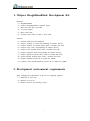
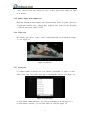
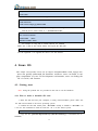
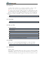
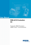
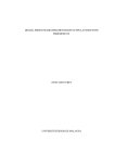
Notes: The first time starting Android OS will take a little time, after this it will be very
quick to start the Android. You can see the Chipsee Logo(it can be changed by using so
ftware ChipSee_LOGO_MOD_EN.exe we provided in the CD)shown on the LCD screen. I
t is successful start When you see the Android desktop like Figure 3-1:
Figure 3-1 Android desktop
3.2. Tests
3.2.1 Touch screen test
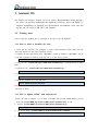
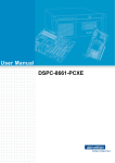
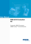
Run MultiTouchTest App, Screen will show the number and position of the touch poi
nt when touching the screen. Resistive screen expansion board only supports single-to
uch, capacitive screen expansion board supports five-point touch like Figure 3-2:
3
Figure 3-2 Touch screen test(Capacitive)
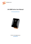
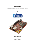
3.2.2 GPIO test(buttons)
The keys on expansion board is defined as shown in Figure 3-3:
HOME
MENU
VOL+
VOLBACK
Figure 3-3 Buttons on board
3.2.3 Buzzer test
Run ChipseeBuzzer App, push “OpenBuzze” button the buzzer will continue to sound.
push “CloseBuzzer” button to stop it.
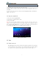
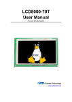
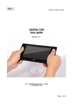
3.2.4 Gravity sensor function test
(1) Gravity sensor can be tested by whirling the screen.
(2) Run SensorList App, in the option “Analog Device 3 axis accelerometer”, You ca
n see real-time changes of the three axis acceleration value curve, like Figure 3-4.
Figure 3-4 Real-time acceleration curve
(3) Use gravity sensing game to test, such as “NFS shift” or “aTilt 3D laby”. If usin
g “NFS shift” , pleas run “ChipseeSensorTool” app to adjust the direction of the axis,
4
select “Invert X axis” and “Swap X/Y axes”, if other games please adjust the settin
gs as default.
3.2.5 Audio input and output test
Insert the microphone and earphone into expansion board Audio IN (pink), Audio OU
T (light blue) interface. Start “Talking Tom” App(Tom Cat), speak into the microphon
e, Tom cat will repeat spoken content
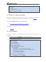
3.2.6 Video test
Run Gallery App, choose “Video”, select “Transformers.Dark of the Moon.2011.720p.a
vi”, like Figure 3-5:
Figure 3-5 Video test
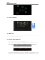
3.2.7 Serial test
(1) Connect COM1 on board to PC. Use software “SecureCRT” or “Putty” or some
others in PC. Run “Serial Port API” App to communicate with PC. Like Figure 3-6.
Figure 3-6 Serial settings
(2) Push button “Send 01010101”, you will see something in PC like Figure 3-7.
(3) Push button “Console”, you can send what you want like Figure 3-8.
5
Figure 3-7 Serial send test
Figure 3-8 Serial receive test
3.3. Build Android4.2 compilation environment
Notes: This work is done under Ubuntu 10.04 64 bit operation system.
3.3.1 Install the required packages
$ sudo apt-get install git-core gnupg flex bison gperf build-essential \
zip curl zlib1g-dev libc6-dev lib32ncurses5-dev ia32-libs \
x11proto-core-dev libx11-dev lib32readline5-dev lib32z-dev \
libgl1-mesa-dev g++-multilib mingw32 tofrodos python-markdown \
libxml2-utils xsltproc minicom tftpd uboot-mkimage expect
Notes: Ensure the PC is connected to the Internet.
3.3.2 Install Oracle JDK 6
1. Copy the file “jdk-6u45-linux-x64.bin” to $HOME.
2. Do the commands shown below:
6
$ chmod a+x jdk-6u45-linux-x64.bin
$ ./jdk-6u45-linux-x64.bin
$ sudo mkdir -p /usr/lib/jvm
$ sudo mv jdk1.6.0_45 /usr/lib/jvm/
$ sudo update-alternatives --install "/usr/bin/java" "java" "/usr/lib/jvm/jdk1.6.0_45/bin/java" 1
$ sudo update-alternatives --install "/usr/bin/javac" "javac" "/usr/lib/jvm/jdk1.6.0_45/bin/javac" 1
$ sudo update-alternatives --config java
$ sudo update-alternatives --config javac
3.3.3 Prepare Android source
1. Copy the file “Chipsee-BBB-JB-42-Source-XXXXXX.tar.gz” to $HOME
2. Extract the file:
$ cd $HOME
$ tar xzvf Chipsee-BBB-JB-42-Source-XXXXXX.tar.gz
You can find what you need under folder “Chipsee-BBB-JB-42-Source-XXXXXX”,
such as “u-boot”, “kernel”:
(1) Android file system source: $HOME/Chipsee-BBB-JB-42-Source-XXXXXX/
(2) Android kernel source: $HOME/Chipsee-BBB-JB-42-Source-XXXXXX/kernel
(3) U-BOOT source: $HOME/Chipsee-BBB-JB-42-Source-XXXXXX/u-boot
(4) Cross-compiler tools: $HOME/Chipsee-BBB-JB-42-Source-XXXXXX/prebuilts/gcc/
linux-x86/arm/arm-eabi-4.6/bin
3. Set Environment Variables
$ cd Chipsee-BBB-JB-42-Source-XXXXXX/
$ source set_env.sh
Notes: For ease of use, The environment variable settings related are written in set_env.
sh script, and run the script only after the current terminal is valid, when the terminal
closed environment variable itself is lost, so in the new terminal need to re-run the scri
pt when Android compiled. And the content of the script is as follows:
export PATH=$PATH:/usr/lib/jvm/jdk1.6.0_45/bin/
export PATH=$PATH:`pwd`/prebuilts/gcc/linux-x86/arm/arm-eabi-4.6/bin
export ARCH=arm
export CROSS_COMPILE=arm-eabi-
3.4. Compile and install the Android system
3.4.1 Compile U-BOOT
1. Go to u-boot folder
$ cd ~/Chipsee-BBB-JB-42-Source-XXXXXX/u-boot/
2. Clear the result compiled before
7
$ make distclean
3. Configure the compile options
$ make am335x_evm_config
4. Compile u-boot
$ make
Notes: Once done, you can find the results under folder “u-boot”, such as “MLO”, “uboot.img”.
3.4.2 Compile kernel
1. Go to kernel folder
$ cd ~/Chipsee-BBB-JB-42-Source-XXXXXX/kernel/
2. Clear the result compiled before
$ make distclean
3. Configure the compile options
$ make am335x_evm_android_defconfig
4. Compile uImage
$ make uImage
Notes: Once done, you can find the result(uImage) under “kernel/arch/arm/boot”
3.4.3 USB-WiFi
If you need the function USB-WiFi, you can do this steps, or go to the next: Compile
Android Filesystem.
1. Go to WiFi folder
$ cd ~/Chipsee-BBB-JB-42-Source-XXXXXX/wifi/rtl8192cu_beaglebone/
2. Compile
$ make
Notes: Once done, you can find the result 8192cu.ko in the current directory, youc
can copy the file to the Android OS root partition directory /system/lib/modules/.
3.4.4 Compile Android Filesystem
1. Go to Android source folder.
$ cd ~/Chipsee-BBB-JB-42-Source-XXXXXX/
2. Compile the Android Filesystem, This case can be compiled according to the host sy
stem of multi-threaded CPU cores, <N> usually 2 times the number of CPU cores.
$ make TARGET_PRODUCT=beagleboneblack OMAPES=4.x –j<N>
8
Notes: Once done, the results located at $HOME/Chipsee-BBB-JB-42-Source-XXXXXX
/out/target/product/beagleboneblack, including both root and system directories
3.4.5 Package image file
1. Go to Android source folder.
$ cd ~/Chipsee-BBB-JB-42-Source-XXXXXX/
2. Package image file
$ make TARGET_PRODUCT=beagleboneblack OMAPES=4.x sdcard_build
Notes: Once done, the results located at $HOME/Chipsee-BBB-JB-42-Source-XXXXXX
/out/target/product/beagleboneblack/beagleboneblack, The content of the directory as d
escribed below:
--Boot_Images
--MLO
// This directory contains all the files needed to start
//AM335x startup file
--u-boot.img
//U-BOOT startup file
--uEnv.txt
//U-BOOT startup parameter configuration file
--uImage
//Android kernel
--Filesystem
//Android filesystem
--rootfs.tar.bz2
--Media_Clips
// Media Files
--Audio
--Images
--Video
--mkmmc-android.sh // SD card installation script
--REDAME.txt
// Instructions
3.4.6 Make a bootable SD card
1. Go to the packaged file folder
$ cd $HOME/Chipsee-BBB-JB-42-Source-XXXXXX/out/target/product/beagleboneblack/beagleboneblack/
2. See 3.1.1 How to make a bootable SD card
3.4.7 Start Android System
See 3.1.2 Start the Android OS, but this Android OS is pure.
3.5. Android system debug in Windows
In this chapter we will describe how to view Android system via the serial port and how
to debug the system via USB OTG. We can also install applications via USB OTG. The
following operation under Windows 7 x64 environment, similar to other Windows platfor
9
ms.
3.5.1 View Android system via the serial port
1. Connect the COM1 on board to PC
2. Open software “SecureCRT” or “Putty” in Windows.
3. Power on the board, you can see the serial output of information like Figure 3-9.
Figure 3-9 Serial output
4. When the system is fully booted, you can communicate with it.
3.5.2 Adb connect via USB OTG
1. Install Oracle JDK 6 for Windows.
2. Install ADT. Download the file here: http://developer.android.com/sdk/index.html.
Extract the file somewhere(named ADT). Adb command located<ADT>\sdk\platform-tools.
3. Optionally, you may want to add the location of the SDK's primary tools directory to
your system PATH. Right-click on My Computer, and select Properties. Under the Advanc
ed tab, hit the Environment Variables button, and in the dialog that comes up, double-clic
k on Path (under System Variables). Add the full path to the tools\ directory to the path.
4. Install Android USB driver: Copy the folder “usb_driver” in CD to <ADT> folder
Boot the board as normal and wait until shell prompt is available (micro-B USB cable m
ust be disconnected).
• Connect micro-B USB cable between board and Windows PC.
• If it is proceeding as planned, Windows will tell you it found a new hardware asks yo
u to install the driver. Install driver that was downloaded as described in step 3 above:
Answer "No, not this time" to the question about running Windows Update to search for
software.
• Choose "Install the hardware that I manually select from a list (Advanced)" this is the
2nd option, then click "Next"
• Select "Show All Devices", then click "Next"
• You are going to see a grayed-out text box with "(Retrieving a list of all devices)", cli
ck the "Have Disk..." button
• Browse" to your driver folder (<ADT>\usb_driver). It will be looking of a .inf file so s
10
elect "android_winusb.inf" and click "Open" then "OK". It's the only file there so you sho
uldn't go wrong.
• Select "Android ADB Interface" then click the "Next" button.
• A warning will appear, answer "Yes" but read the warning anyway.
• Click the "Close" when the wizard is completed.
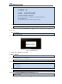
Now you can see the driver is installed successfully link Figure 3-10.
Figure 3-10 ADB driver
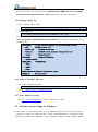
5. Test adb: “Win+r” enter “cmd”, test like below:
> cd <ADT>\sdk\platform-tools\
> adb kill-server
> adb start-server
> adb devices
> adb shell
When the "#" prompt appears, it means we connect the board with PC successfully.
Figure 3-11 ADB Command
Now you can use Linux commands like “ls”, “cd” and so on. Ctrl + C to exit the shell
return to Windows system.
6. Use adb command to install Android App: for example SogouInput.apk.
> adb install SogouInput.apk
If there is a “Success”, the app has already installed in Android.
Figure 3-12 Install App
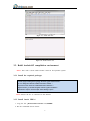
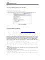
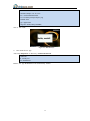
7. Use adb command to uninstall App
(1) Uninstall user app(such as SogouInput.apk): Use command “pm list” to get the full nam
e of the app, like Figure 3-13. Then use command “uninstall” to uninstall the app.
11
> adb shell pm list packages
> adb uninstall com.sohu.inputmethod.sogou
Figure 3-13 Command “pm list” to get app’s name
(2) Uninstall default app: Use “adb shell” to log in the board and delete the apk file.
> adb shell
# cd /system/app/
# ls
# rm Browser.apk
8. Use adb command to transport files between board and PC: “adb pull” and “adb push”
(1) Board to PC: <remote> is the file or folder on board, <local> is the file or fold
er in PC.
>adb pull <remote> <local>
(2) PC to board:
>adb push <local> <remote>
For example copy <ADT>\sdk\platform-tools\chipsee.txt to board:
>adb push chipsee.txt /chipsee.txt
Opposite, board to PC:
>adb pull /testFile.txt testFile.txt
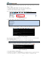
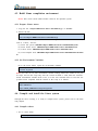
3.5.3 Adb connect via internet
Make sure Ethernet port on board and host machine are connected to the network. C
heck Ethernet configuration for the board
# netcfg
lo
UP
127.0.0.1
255.0.0.0
eth0
UP
192.168.1.117/24
0x00000049
255.255.252.0
0x00001043
1. If Ethernet was not configured, configure Ethernet of the board using ifconfig/netc
fg as shown below.
# netcfg eth0 dhcp
2. Configure the ADB Daemon to use an ethernet connection using setprop as show
n below.
# setprop service.adb.tcp.port 5555
3. If network is configured successfully (above steps) then Restart service adbd on t
he target
12
# stop adbd
# start adbd
4. On the host machine use following commands to establish adb connection
$ adb kill-server
$ adb start-server
$ adb connect <target_ip_address>:5555
5. Verify for device connectivity, by executing the following commands. If connected,
find the device name listed as a "IPADDRESS:PORT"
$ adb devices
List of devices attached
emulator-5554
device
192.168.1.117:5555
6.
device
An example of using adb to install software for Android
Make sure **.apk at the current folder, and export the adb path
$ adb –s 192.168.1.117:5555 install **.apk
Use the argument –s to appoint the device over the internet.
4. Linux OS
This chapter will introduce Linux OS for Chipsee BeagleBoneBlack board, through this,
users can quickly understand the hardware resources; users can build a com
plete compilation of Linux OS development environment; users can debug the
OS via serial, and Internet.
4.1. Getting start
Note: Using the prebuilt file we provided in the CD to test the hardware.
4.1.1 How to make a bootable SD card
1. Insert the SD card into your computer, if using virtual machines, please make sure
the SD card mounted to the Linux operating system.
2. Confirm the SD card mount point, “/dev/sdX”, usually it should be “/dev/sdb”. Yo
u can use this command to find out what the “X” is in the Linux system.
$ sudo fdisk –l
3. Copy the file “prebuilt-chipsee-bbb-exp-ezsdk-20131210.tar.gz” somewhere(such as
$HOME).
13
4. Extract the file “Prebuilt-chipsee-bbb-exp-ezsdk-20131210.tar.gz”
$ tar xzvf Prebuilt-chipsee-bbb-exp-ezsdk-20131210.tar.gz
5. Go to the folder “Prebuilt-chipsee-bbb-exp-ezsdk-20131210”
$ cd ~/Prebuilt-chipsee-bbb-exp-ezsdk-20131210
6. Flash the Linux OS to the SD card
$ sudo ./mksdcard.sh --device /dev/sd<?>
Notes: The SD card should be at least 2GB, and you’d better to use Sandisk Class4 level
SD card or above.
4.1.2 How to update eMMC with Linux OS
Follow the steps in chapter 4.1.1 to make a bootable SD card for eMMC-flasher, you fin
d the file prebuilt-BBB-Exp-eMMC-flasher-XXXXXX.tar.gz in CD.
1. Extract “prebuilt-BBB-Exp-eMMC-flasher-XXXXXX.tar.gz”
$ tar xzvf prebuilt-BBB-Exp-eMMC-flasher-XXXXXX.tar.gz
2. Go to the folder “prebuilt-BBB-Exp-eMMC-flasher-XXXXXX”
$ cd ~/prebuilt-BBB-Exp-eMMC-flasher-XXXXXX
3. Run the command to make a bootable SD card
$ sudo ./mksdcard.sh --device /dev/sd<?> --system Linux
4. It will finished in about 10 minutes. Once done switch SW8 to “uSD”, then insert the
SD card and power on the board. The screen will be dark.
5. Wait for almost 30 minutes, when all the four user LEDs on Beaglebone Black stay lit.
It is done.
6. Power off the board, pull out of the SD card from Beaglebone Black, switch SW8 to
"eMMC", then power on.
4.1.3 Start the Linux OS
1. Insert SD card into BeagleBoneBlack
2. Switch SW8 on expansion board to uSD
3. Power on the board
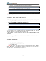
Notes: You can see the Chipsee Logo(it can be changed by using software ChipSee_
LOGO_MOD_EN.exe we provided in the CD)shown on the LCD screen. It is successful s
tart When you see the Linux desktop like Figure 4-1:
14
Figure 4-1 Linux desktop
4.2. Tests
4.2.1 Touch screen and buzzer test
Click on the screen, the mouse arrow stays in position triggered and the buzzer soun
ds, indicating that touch and buzzer work properly. After working for some time resis
tive touch screen may not be accurate, need to be calibrated, click on the “Chipsee”
icon on desktop, select “Calibrate Screen” to calibrate. Like Figure 4-2:
Figure 4-2 Resistive touch screen calibration app
4.2.2 Audio and video test
Click “Multimedia” icon on desktop, choose “MPEG-4+AAC Dec” to test. You need
insert the earphone into expansion board Audio OUT (light blue) before testing. The
result like Figure 4-3:
Figure 4-3 Audio and video
15
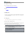
4.2.3 3D test
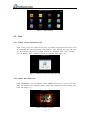
Click “3D” icon on desktop, choose “Film TV” to test. Like Figure 4-4:
Figure 4-4 3D test Film TV
4.2.4 Serial test
(1) Connect COM1 on board to PC. Use software “SecureCRT” or “Putty” or some
others in PC. Click on the “Chipsee” icon on desktop, select “SerialTest” to run “Ser
ialTest” App to communicate with PC. Like Figure 4-5.
Figure 4-5 Serial test
Note: There are only three serial ports available on board, one is RS232(COM1), the
others are RS485(COM3 and COM4). And COM1(RS232) is used to debug the syste
m, if you want to use it by your own. See 6.1.2 Use the debug serial port.
When you start the test. It will send string "Succeed in sending message!!!" every tw
o seconds. Click on the "SendMSG" button, it will send string "Succeed in sending
message-manual!!!". Every two seconds, it will read the received buffer, show the res
ult to the received area.
16
4.3. Build Linux compilation environment
Notes: This work is done under Ubuntu 10.04 64 bit operation system.
4.3.1 Prepare Linux source
1. Copy the file “Chipsee-BBB-Linux-Source-20130902.tar.gz” to $HOME.
2. Extract the file:
$ cd $HOME
$ tar xzvf
Chipsee-BBB-Linux-Source-20130902.tar.gz
You can find what you need under folder “Chipsee-BBB-Linux-Source-20130902”,
such as “u-boot”, “kernel”:
(1) Linux file system: $HOME/Chipsee-BBB-Linux-Source-20130902/filesystem
(2) Linux kernel source: $HOME/Chipsee-BBB-Linux-Source-20130902/kernel
(3) U-boot source: $HOME/Chipsee-BBB-Linux-Source-20130902/u-boot
(4) Cross-compiler tools: $HOME/Chipsee-BBB-Linux-Source-20130902/linux-devkit/b
in
4.3.2 Set Environment Variables
Go to the source folder, export the environment variables
$ cd Chipsee-BBB-Linux-Source-20130902/
$ source set_env.sh
Notes: For ease of use, The environment variable settings related are written in set_env.
sh script, and run the script only after the current terminal is valid, when the terminal
closed environment variable itself is lost, so in the new terminal need to re-run the scri
pt when Linux compiled. And the content of the script is as follows:
export PATH=$PATH:`pwd`/linux-devkit/bin
export ARCH=arm
export CROSS_COMPILE=arm-arago-linux-gnueabi-
4.4. Compile and install the Linux system
Through the above settings, it is ready to compile Linux system, please refer to the follo
wing chapter.
4.4.1 Compile u-boot
1. Go to u-boot folder
$ cd ~/Chipsee-BBB-Linux-Source-20130902/u-boot/
17
2. Clear the result compiled before
$ [ -d ./am335x ] && rm -rf ./am335x
3. Compile u-boot
$ make O=am335x am335x_evm
Notes: Once done, you can find the results under folder “$HOME/Chipsee-BBB-LinuxSource-20130902/u-boot/am335x/”, such as “MLO”, “u-boot.img”.
4.4.2 Compile kernel
1. Go to kernel folder
$ cd ~/Chipsee-BBB-Linux-Source-20130902/kernel/
2. Clear the result compiled before
$ make distclean
3. Configure the compile options
$ make am335x_evm_defconfig
4. Compile uImage
$ make uImage
Notes: Once done, you can find the result(uImage) under “kernel/arch/arm/boot/”
4.4.3 Package image file
1. Go to Linux source folder.
$ cd ~/Chipsee-BBB-Linux-Source-20130902/
2. Do the command to package the files
$ ./sdcard_build.sh --directory beagleboneblack
Notes: Once done, the results located at “$HOME/Chipsee-BBB-Linux-Source-2013090
2/beagleboneblack”, The content of the directory as described below:
--boot
// This directory contains all the files needed to start
--MLO
// AM335x startup file
--u-boot.img
// U-BOOT startup file
--uEnv.txt
// U-BOOT startup parameter configuration file
--uImage
// Linux kernel
--pointercal
// calibrate date file
--filesystem
// Linux filesystem
--rootfs.tar.bz2
--mksdcard.sh
--REDAME
// SD card installation script
// Instructions
18
4.4.4 Make a bootable SD card
1. Insert the SD card into Ubuntu system.
2. Go to folder “beagleboneblack”
$ cd $HOME/Chipsee-BBB-Linux-Source-20130902/beagleboneblack/
3. Do the command like 4.4.1 How to make a bootable SD card.
$ sudo ./mksdcard.sh --device /dev/sd<?>
4.4.5 Start Linux system
See 4.1.2 Start the Linux OS.
4.5. Linux OS Debug
In this chapter we will describe how to view Linux system via the serial port and how to
debug program via Internet by using NFS.
4.5.1 View the system infomation via the serial port
1. Connect the COM1 on board to PC
2. Open software “SecureCRT” or “Putty” in Windows.
3. Power on the board, you can see the serial output of information like Figure 4-6.
Figure 4-6 Serial output
4. When the system is fully booted, you can communicate with it(user: root, no pass
word).
4.5.2 NFS
Embedded Qt has been in Linux system, The development environment is Ubuntu12.04, m
ore information you can find in CD we provided《User Guide For Embedded Qt.docx》
We assume the development environment is ready.
19
1. Install NFS in Ubuntu
$sudo apt-get install nfs-kernel-server
2. Configure the file “/etc/exports”, add this at the end of file:
/qtprojects *(rw, sync, insecure, no_subtree_check)
Note:
“/qtprojects”: the shared folder in Ubuntu system;
“*”: allows all other PC to get access to this system;
“rw”: means this folder can be read and write by NFS client;
“sync”: synchronous write memory and hard disk;
“insecure”: sent message through the port above 1024;
“no_subtree_check”: no check the parent directory permissions
3. Restart NFS service
$ sudo /etc/init.d/portmap restart
$ sudo /etc/init.d/nfs-kernel-server restart
4. Test
$ showmount -e
or mount the shared folder to /mnt:
$ sudo mount -t nfs –o nolock localhost:/qtprojects /mnt
umount /mnt
$ sudo umount /mnt
5. Mount NFS on board
Create a directory
# mkdir /nfsdir
Mount the folder /qtprojects in Ubuntu to /nfsdir on board
# mount –t nfs <NFS-SERVER-IP>:/qtprojects /nfsdir
If you have an executable program like “SerialTest” under folder “/qtprojects”, you ca
n run it directly on board.
# /nfsdir/SerialTest
20
5. Angstrom OS
This chapter will introduce Angstrom OS for Chipsee BeagleBoneBlack board, through t
his, users can quickly understand the hardware resources; users can debug the
OS via serial, and Internet.
5.1. Getting start
Notes: Using the prebuilt file we provided in the CD to test the hardware.
5.1.1 How to make a bootable SD card
1. Insert the SD card into your computer, if using virtual machines, please make sure the
SD card mounted to the Ubuntu(or other Linux) operating system.
2. Confirm the SD card mount point, “/dev/sdX”, usually it should be “/dev/sdb”. You ca
n use this command to find out what the “X” is in the Linux system.
$ sudo fdisk –l
3. Copy the file “prebuilt-angstrom-XXXXXX.rar” somewhere(such as $HOME).
4. Extract the file “prebuilt-angstrom-XXXXXX.rar”
5. Go to the folder “prebuilt-angstrom-XXXXXX”
$ cd ~/prebuilt-angstrom-XXXXXX
6. Flash the Angstrom OS to the SD card
$ sudo ./mksdcard.sh --device /dev/sd<?>
5.1.2 How to update eMMC with Angstrom OS
See chapter 4.1.2 How to update eMMC with Linux OS
5.1.3 Start the Angstrom OS
1. Insert SD card into BeagleBoneBlack
2. Switch SW8 on expansion board to uSD
3. Power on the board
Notes: You can see the Chipsee Logo(it can be changed by using software ChipSee_LOG
O_MOD_EN.exe we provided in the CD) shown on the LCD screen. It is successful start
When you see the Angstrom desktop like Figure 5-1:
21
Figure 5-1 Angstrom desktop
5.2. Tests
5.2.1 Touch screen and buzzer test
Click on the screen, the mouse arrow stays in position triggered and the buzzer soun
ds, indicating that touch and buzzer work properly. After working for some time resis
tive touch screen may not be accurate, need to be calibrated: firstly remove the file /
etc/pointercal.xinput, then click on the SystemAdministrationCalibrate Touchscree
n on desktop to calibrate, more information you can find “Angstrom Resistive Touc
hsreen Calibration Steps.pdf”
5.2.2 Audio test
Start terminal, then use command mplayer to test.
# mplayer FILENAME
//such as: mplayer ~/chipsee/Music/AudioTest.aac
5.2.3 Serial test
1. Connect COM1 on board to PC. Use software “SecureCRT” or “Putty” or some
others in PC. Connect keyboard and mouse to the board. Then press “Ctrl+Alt+F1(or
F3~F6)” to get into tty1(tty3~tty6), enter user name root, no password. Go to chipse
e folder start the test, Like Figure 5-2.
Notes: The QtE in Angstrom OS is not working well, by now user only can use mo
use for the Qt apps.。
# cd chipsee
# ./ChipseeTest -qws
22
Figure 5-2
ChipseeTest
Note: There are three serial ports available on board, one RS232(COM1), the others a
re RS485(COM3 and COM4). And COM1(RS232) is used to debug the system, the b
aud rate is 115200.
2. Serial test: at the serial area, set Com COM2, set Baud 115200, click on “Open”
It will send string "Succeed in sending message!!!" every two seconds. Click on the
"SendMSG" button, it will send string "Succeed in sending message-manual!!!". Every
two seconds, it will read the received buffer, show the result to the received area.
5.2.4 Network test
Click on “Network”, then click on “Ifconfig” to view the network information on boa
rd, click on “Refresh” to restart the network service, it will take five or six seconds
to finish. Like Figure 5-3:
Figure 5-3 Network infomation
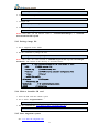
5.2.5 Date&Time
Click the time display area “Edit” icon to set the time and date, like Figure 5-4:
23
Figure 5-4 Date and Time
5.2.6 Backlight
By modifying the size “Backlight” can change the brightness of the backlight..
5.2.7 USB Devices
1. USB webcam
If you want to use USB webcam, you need to connect the webcam to the board bef
ore power on. Then choose ApplicationSound&VideoCheese Webcam Booth to ta
ke pictures.
2. USB-Wifi module
If you want to use USB-Wifi module in the system, you need to edit the file /var/lib
/connman/wifi.config, modify the router, the login name and password, save and rebo
ot. The system will automatically connect the next time you start, the contents are as
follows:
Type = wifi
Name = chipsee //router’s name
Security = AES //security mode
Passphrase = 1234567890 //password
5.3. Build Angstrom compilation environment
Notes: This work is done under Ubuntu 10.04 64 bit operation system.
5.3.1 Prepare Angstrom source
1. Copy the file “Angstrom-bbb-exp-source-0210.tar.gz” to $HOME.
2. Extract the file:
$ cd $HOME
$ tar xzvf
Angstrom-bbb-exp-source-0210.tar.gz
24
You can find what you need under folder “Angstrom-bbb-exp-source-0210”, such a
s “u-boot”, “kernel”:
(1) Linux file system: $HOME/Angstrom-bbb-exp-source-0210/filesystem
(2) Linux kernel source: $HOME/Angstrom-bbb-exp-source-0210/kernel*
(3) U-boot source: $HOME/Angstrom-bbb-exp-source-0210/u-boot*
(4) Cross-compiler tools: $HOME/Angstrom-bbb-exp-source-0210/gcc-linaro-arm-linu
x-gnueabihf-4.7-2013.04-20130415_linux
5.3.2 Set Environment Variables
Go to the source folder, export the environment variables
$ cd
Angstrom-bbb-exp-source-0210/
$ source setEnv.sh
Notes: For ease of use, The environment variable settings related are written in setEnv.
sh script, and run the script only after the current terminal is valid, when the terminal
closed environment variable itself is lost, so in the new terminal need to re-run the scri
pt when Android compiled. And the content of the script is as follows:
export PATH=`pwd`/gcc-linaro-arm-linux-gnueabihf-4.7-2013.04-20130415_linux/bin:$PATH
export CROSS_COMPILE=arm-linux-gnueabihfexport ARCH=arm
5.4. Compile and install the Angstrom system
Through the above settings, it is ready to compile Angstrom system, please refer to the fo
llowing chapter.
5.4.1 Compile u-boot
1. Go to u-boot folder
$ cd ~/Angstrom-bbb-exp-source-0210/u-boot*/
2. Clear the result compiled before
$ [ -d ./am335x ] && rm -rf ./am335x
3. Compile u-boot
$ make O=am335x am335x_evm
Notes: Once done, you can find the results under folder “am335x/”, such as “MLO”,
“u-boot.img”.
5.4.2 Compile kernel
1. Go to kernel folder
25
$ cd ~/Angstrom-bbb-exp-source-0210/kernel*/
2. Clear the result compiled before
$ make distclean
3. Configure file
$ cp config-chipsee .config
4. Compile uImage
$ make dtbs uImage
Notes: Once done, you can find the results: 1. “arch/arm/boot/uImage”, 2. “arch/arm/
boot/dts/am335x-bbb-exp.dtb
5.4.3 Package image file
1. Go to Angstrom source folder.
$ cd ~/Angstrom-bbb-exp-source-0210/
2. Do the command to package the files
$ ./sdcard_build.sh --directory beagleboneblack
Notes: Once done, the results located at “$HOME/Angstrom-bbb-exp-source-0210/beagle
boneblack”, The content of the directory as described below:
--boot
// This directory contains all the files needed to start
--MLO
// AM335x startup file
--u-boot.img
// U-BOOT startup file
--uEnv.txt
// U-BOOT startup parameter configuration file
--uImage
// kernel
--am335x-bbb-exp.dtb
--filesystem
// filesystem
--*rootfs*.tar.bz2
--mksdcard.sh
--REDAME
// SD card installation script
// Instructions
5.4.4 Make a bootable SD card
1. Insert the SD card into Ubuntu system.
2. Go to folder “beagleboneblack”
$ cd $HOME/Angstrom-bbb-exp-source-0210/beagleboneblack/
3. Do the command like 5.1.1 How to make a bootable SD card.
$ sudo ./mksdcard.sh --device /dev/sd<?>
5.4.5 Start Angstrom system
See 5.1.2 Start the Angstrom OS.
26
5.5. Angstrom OS Debug
5.5.1 View Angstrom system via the serial port
See 4.5.1 View the system infomation via the serial port.
5.5.2 NFS
See 4.5.2 NFS.
6. Debian OS
This chapter will introduce Debian OS for Chipsee BeagleBoneBlack board, through this,
users can quickly understand the hardware resources; users can debug the O
S via serial, and Internet.
6.1. Getting start
Notes: Using the prebuilt file we provided in the CD to test the hardware.
6.1.1 How to make a bootable SD card
1. Insert the SD card into your computer, if using virtual machines, please make sure the
SD card mounted to the Ubuntu(or other Linux) operating system.
2. Confirm the SD card mount point, “/dev/sdX”, usually it should be “/dev/sdb”. You ca
n use this command to find out what the “X” is in the Angstrom system.
$ sudo fdisk –l
3. Copy the file “prebuilt-debian-XXXXXX.tar.gz” somewhere(such as $HOME).
4. Extract the file “prebuilt-debian-XXXXXX.tar.gz”
$ tar zxfv
prebuilt-debian-XXXXXX.tar.gz
5. Go to the folder “prebuilt-debian-XXXXXX”
$ cd ~/prebuilt-debian-XXXXXX
6. Flash the Angstrom OS to the SD card
$ sudo ./mksdcard.sh --device /dev/sd<?>
27
6.1.2 How to update eMMC with Debian OS
See chapter 4.1.2 How to update eMMC with Linux OS
6.1.3 Start Debian OS
1. Insert SD card into BeagleBoneBlack
2. Switch SW8 on expansion board to uSD
3. Power on the board
Notes: You can see the Chipsee Logo(it can be changed by using software ChipSee_LOG
O_MOD_EN.exe we provided in the CD) shown on the LCD screen. It is successful start
When you see the Debian desktop like Figure 6-1:
Figure 6-1 Debian desktop
6.2. Tests
6.2.1 Touch screen and buzzer test
Click on the screen, the mouse arrow stays in position triggered and the buzzer soun
ds, indicating that touch and buzzer work properly. After working for some time resis
tive touch screen may not be accurate, need to be calibrated: choose PreferencesCa
librate Touchscreen app to recalibrate, but it only works this time, if you reboot the
System, you need to do it again. You can do it this way: delete the file /etc/pointerc
al.xinput, then reboot. You will see the calibrate app first before you access to the s
ystem. Just calibrate, the result will saved.
6.2.2 Audio test
Start terminal, then use command mplayer to test.
# mplayer FILENAME
//如 mplayer ~/Music/test.mp3
28
6.2.3 Serial test
1. Connect COM1 on board to PC. Use software “SecureCRT” or “Putty” or some
others in PC. You will see the system information when the system start.
Note: There are three serial ports available on board, one is RS232(COM1), the other
s are RS485(COM3 and COM4). And COM1(RS232) is used to debug the system, b
aud rate is 115200. Users can communicate with the OS via it, just as Terminal did.
2. Serial test: Use software “SecureCRT” or “Putty” or some others in PC. Set baud rate
as 9600.
# echo “This is a test” > /dev/ttyO2
You will see the string in PC, then change the ttyO1 to ttyO2/ttyO4 to test RS485_2.
6.2.4 Networking
# ifconfig –a
You can see the information of CAN0, eth0.
6.2.5 Date and Time
Check the system time
# date
Set the system time
# date –s “2014-03-15 10:30:30”
Check RTC
# hwclock
Write RTC
# hwclock –w
Modify the time zone, such as China:
# ln -sf /usr/share/zoneinfo/Asia/Hong_Kong /etc/localtime
6.2.6 Backlight
Modify the file /sys/class/backlight/backlight.8/Brightness to change the backlight.
range from 0 to 100, 0 means shutdown the backlight, 100 is the MAX value.
# echo 50 > /sys/class/backlight/backlight.8/Brightness
6.2.7 USB Devices
USB-Wifi module
If you want to use USB-Wifi module in the system, you need to edit the file /etc/net
work/interfaces, modify the router, the login name and password, save and reboot. Th
e system will automatically connect the next time you start, the contents are as follo
29
ws:
#Wifi Example
auto wlan0
iface wlan0 inet dhcp
wpa-ssid "Chipsee" //router’s name
wpa-psk "1234567890" //password
6.3. Debian OS Compile and Debug
Note: The u-boot and kernel of Debian OS are the same as Angstrom’s. The difference b
etween them is the system files. More details about compile you can see chapter 5.4.
6.3.1 View Angstrom system via the serial port
See 4.5.1 View the system infomation via the serial port.
6.3.2 NFS
See 4.5.2 NFS.
6.4. Java for Debian
This chapter we will setup the environment of Java, and show you how to a simple Java
application.
1. Install jdk(Use command java -version to see the jdk is installed or not)
# sudo apt-get install openjdk-6-jdk
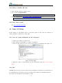
2. Edit a simple program HelloWorld.java
import java.awt.Color;
import java.awt.Font;
import java.awt.Toolkit;
import javax.swing.JFrame;
import javax.swing.JTextField;
public class HelloWorld extends JFrame{
public HelloWorld(){
JTextField text = new JTextField("Hello, world!");
text.setFont(new Font("Times New Roman",Font.BOLD,60));
text.setForeground(Color.BLACK);
this.getContentPane().add(text);
}
public static void main(String argv[]){
HelloWorld win = new HelloWorld();
30
Toolkit tk = Toolkit.getDefaultToolkit();
int winWidth = 512;
int winHeight = 300;
int Width = tk.getScreenSize().width;
int Height = tk.getScreenSize().height;
win.setSize(winWidth, winHeight);
win.setLocation((Width-winWidth)/2, (Height-winHeight)/2);
win.setVisible(true);
win.setDefaultCloseOperation(EXIT_ON_CLOSE);
}
}
3. Compile the source
# javac HelloWorld.java
This will be very slow in Debian OS, we suggest do it in your PC, you need install
jdk-1.6 first.
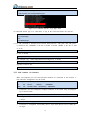
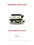
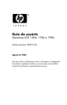
4. Run the program
# java HelloWorld
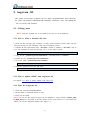
You will see this:
Figure 6-2 HelloWorld (1)
5. Adding Java program to Quick Start
a) Make a directory
# mkdir /usr/lib/java/
b) Copy HelloWorld.class to /usr/lib/java/
# cp HelloWorld.class /usr/lib/java/
c) Edit script /usr/bin/HelloWorld.sh like this:
#!/bin/bash
cd /usr/lib/java/
java HelloWorld
Change the permissions of the script
# sudo chmod a+x HelloWorld.sh
d) Edit file /usr/share/applications/javatest.desktop like this:
[Desktop Entry]
31
Name=HelloWorld
Comment=Simple test for Java
Exec=/usr/bin/HelloWorld.sh
Icon=/usr/share/pixmaps/chipsee.png
Terminal=false
Type=Application
Categories=GTK;Utility;GNOME;
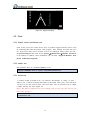
This is the result:
Figure 6-3 HelloWorld(2)
6. Auto-Launch Java app
Add script 89javatest in directory /etc/X11/Xsession.d/ :
#!/bin/bash
cd /usr/lib/java/
java HelloWorld
Reboot, the app HelloWorld will automatically launch.
32
7. Customized
In this chapter users can change some settings for the systems, such as the Logo wh
en the OS started.
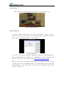
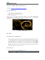
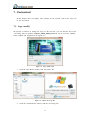
7.1. Logo modify
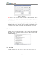
We provide a software to change the Logo we the OS start, you can find the tool in the
CD along with our product: ChipSee_LOGO_MOD_EN.exe.(It can be used for Android,
Linux, Debian and Angstrom) Like Figure 7-1:
Figure 7-1 Logo modify App
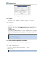
1. Click the first Browse button, find the picture file.
Figure 7-2 Choose the Logo file
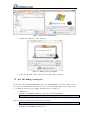
2. Click the second Browse button, find the u-boot.img file.
33
Figure 7-3 Choose the u-boot.img file
3. Choose the resolution , click “Execute”.
Figure 7-4 Change the Logo successful
4. Insert the SD card, power the board, the Logo will be replaced.
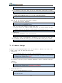
7.2. Use the debug serial port
In the four OS for BeagleBoneBlack board. The COM1(RS232) is used as debug serial p
ort, users can communicate with the OS via it, just as Terminal did. If users want to use
it as normal serial port, this chapter will show how to change it.
1. Android OS
Edit the file uEnv.txt which you can find in the boot partition.
bootargs=console=ttyO1,115200n8 androidboot.console=ttyO1
Change it to ttyO2 or ttyO4(RS485_1 and RS485_2), you can change it to ttyO0,
then you can use all the three serial ports as normal.
bootargs=console=ttyO0,115200n8 androidboot.console=ttyO0
2. Linux OS
Edit the file /etc/inittab around line 31:
34
S:2345:repawn:/sbin/getty 115200 ttyO1
Change it to ttyO2 or ttyO4(RS485_1 and RS485_2), you can add "#" before this
line to comments off this line. Then you can use all the three serial ports as normal.
# S:2345:repawn:/sbin/getty 115200 ttyO1
3. Angstrom OS
(1) Edit the file uEnv.txt which you can find in the boot partition.
bootargs=console=ttyO1,115200n8
Change it to ttyO2 or ttyO4(RS485_1 and RS485_2), you can change it to ttyO0,
then you can use all the three serial ports as normal.
(2) Stop the service in Angstrom.
# systemctl disable [email protected]
# systemctl stop [email protected]
Now you can use the COM1 as normal serial port.
(3) If you want to use COM1 as debug serial port, you need to edit the file uE
nv.txt which you can find in the boot partition. And start the service:
# systemctl start [email protected]
4. Debian OS
Edit the file /etc/inittab , at the end of the file:
T0:23:respawn:/sbin/getty –L ttyO0 115200 vt102
Change it to ttyO2 or ttyO4(RS485_1 and RS485_2), you can add "#" before this
line to comment off this line. Then you can use all the three serial ports as normal.
# T0:23:respawn:/sbin/getty –L ttyO0 115200 vt102
7.3. IP address Settings
In the three OS for BeagleBoneBlack board. The IP address is DHCP, if you want to use
is used as static. You can follow the steps below.
1. Android OS
Edit the file uEnv.txt which you can find in the boot partition.
bootargs=console=ttyO0,115200n8 androidboot.console=ttyO0 mem=512M root=/dev/mmcblk0p2 r
w rootfstype=ext4 rootwait init=/init ip=off
Edit the red part like this:
ip=<client-ip>:<server-ip>:<gw-ip>:<netmask>:<hostname>:<device>:<autoconf>:<dns0-ip>:
<dns1-ip>
For example:
bootargs=console=ttyO0,115200n8 androidboot.console=ttyO0 mem=512M root=/dev/mmcblk0p2 r
w rootfstype=ext4 rootwait init=/init ip=192.168.1.111:::255.255.0.0
2. Linux and Debian OS
Edit the file /etc/network/interfaces like this:
auto eth0
iface eth0 inet static
35
address 192.168.1.111
gateway 192.168.1.1
netmask 255.255.0.0
Restart the network service.
# /etc/init.d/networking restart
About us:
Chipsee Information Technology Co.,Ltd
Room 1004, Mansion Haojing 3#,Zhichun Road 108
Haidian District, Beijing, China,100080
TEL:+86-10-62561127
E-Mail: [email protected]
Web: www.chipsee.com
36