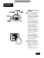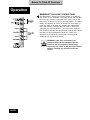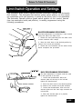
1
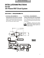
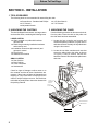
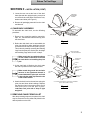
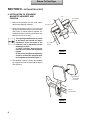
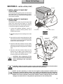
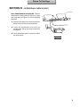
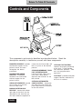
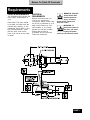
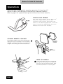
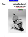
Go To Operation Section
Installation Manual
391 Power ENT Chair System
To purchase a printed copy of this manual,
click on the "Place Order" button below.
Place Order
Style F*
Return To First Page
Return To First Page
INSTALLATIONINSTRUCTIONS
for the
391 Power ENT Chair System
SECTION I - REQUIREMENTS
1. PHYSICAL REQUIREMENTS
2. ELECTRICAL REQUIREMENTS:
Before installing the chair ensure that the physical
requirements are met (See Figure 1). The chair
should be at least 18 inches from the nearest wall,
cabinet, or any permanent fixture when in the fully
reclined position. Note that the chair seat moves
back 4-1/2 inches as the base is raised.
Before connecting the line cord to an appropriate
receptacle, make certain that the circuit is protected
by a 15-amp circuit breaker for 120-VAC models,
or a 7.5-amp breaker for 240-VAC models. Ensure
that all wiring is grounded and all electrical codes
are observed.
WARNING - Potential shock hazard
with possible personal injury. To
reduce shock hazard, observe all
electrical codes.
69" (175.2 cm) S U P IN E
OU T L INE OF B AS E P L AT E
9.5"
(24.1 cm)
8.5"
(21.6 cm)
25.5"
(64.7 cm)
10"
(25.4 cm)
16"
(40.6 cm)
17"
(43 cm)
13.0"
(33.0 cm)
63" MAX
(.160.0 cm)
50" MIN
(127 cm)
MAX U P R IGH T P OS IT ION
8 F R OM VE R T ICAL
0
Figure 1
MAX S U P INE P OS IT ION
AB OVE H OR IZ ONT AL
P R OGR AM - 22
MANU AL - 14
0
0
39.5" MAX
(100.3 cm)
26.5" MIN
(67.3 cm)
38" MAX
(96.5 cm)
25" MIN
(63.5 cm)
F L OOR
A F11 3 0
30.5"
(77.5 cm)
28"
(71 cm)
4"
(10 cm)
42"
(106.7 cm)
31" MAX
(78.7 cm)
18" MIN
(45.7 cm)
0
360 R OT AT ION AB OU T CE NT E R L IN E
1
Return To First Page
SECTION II - INSTALLATION
1. TOOLS REQUIRED
The following tools are recommended for assembling the chair:
l Screwdrivers - Standard and Phillips
l 1/2" Wrench
l Adjustable Wrench
2. UNPACKING THE CARTONS
l 1/8" Allen Wrench
l 7/16" Wrench
3. UNPACKING THE CHAIR
The chair is shipped in two cartons, one large carton
and a smaller carton, containing the following items:
Use the following procedure to disconnect the chair
from the pallet. Leave the chair on the pallet until
the chair back has been assembled.
LARGE CARTON
l Chair mounted on a pallet with backrest
disconnected
l Plastic bag containing installation hardware
and warranty card
l Installation instructions (this manual) and
operator’s manual
l Foot Control
l Headrest and Cushion
1. Locate the foot controller and remove and
discard the packing material. Plug the chair in
and raise the chair vertically off the pallet brace
using the foot control.
2. Locate the two bolts, washers and nuts that
secure the pallet cleat to the pallet, as shown
in Figure 2. Using a wrench, remove this
hardware. Remove and discard the pallet brace
and cleat.
SMALL CARTON
l Seat Cushion
l Back Cushion
l A Set of Armrests
l Hardware Kit
Check for signs of damage to either carton or to
the contents and that all items listed above are
present. If there is any evidence of damage due to
shipping or if any of the items is missing from the
cartons, notify the shipper at once. Be careful not
to discard any small parts or instruction sheets with
the packing material.
PALLET
SH IPPIN G
BR A C E
PALLET
C LEAT
WAS H ER A ND N U T
C ARR IAG E B O LT
Figure 2
2
Return To First Page
SECTION II - INSTALLATION (CONT)
3. Locate the two nuts at the front of the chair
base (beneath the upright housing cover) that
secure the chair to the pallet. Remove the nuts,
washers and bolts (see Figure 3).
U P R IG H T
H O U S IN G
COVER
4. Remove all packaging material from the chair
and discard.
4. CHAIR BACK ASSEMBLY
NUT AND W ASHERS
To assemble the chair back, use the following
procedure:
PA L LE T
1. Remove any remaining packing materials,
tape, etc., and discard. Remove the tag from
the seat frame.
C H A IR B A S E
Figure 3
2. Before the chair back can be assembled, the
pivot pins and short white bushings must be
removed from the tow bar end (See Figure 4).
This is done by carefully removing the retaining
rings from the pivot pins. Set the pins, bushings
and retaining rings aside for use in step 4.
Make certain the long white bushings
are left seated in the holes in the tow
bar ends before re-installing the pivot
pins.
W IR E H A R N E S S
A N D G R O U N D W IR E
P IV O T P IN
SHORT
W H ITE
B U S H IN G
C H A IR B A C K
CHANN EL
C L E V IS
END
3. As the chair back is lifted up, the clevis ends
will slide in position over the tow bar ends.
Make certain the ground wire and wire
harness in the right-hand channel is
located behind the pivot pin and held
in place by the cable clip located on the
inside of the tow bar.
4. Attach the chair back to the tow bars using the
pivot pins and short white bushings. Replace
the retaining rings in the grooves at the end of
each pivot pin to lock the pins in place.
Lubricate each joint with a drop of light
weight oil.
S H O R T W H ITE
B U S H IN G
R E TA IN IN G
R IN G
TO W B A R
END
L ON G W H ITE
B U S H IN G
C A B LE C LIP
IL LU S TR ATIO N S H O W IN G C H A IR B A C K A S S E M B LY
(R IG H T -H A N D S ID E S H O W N )
Figure 4
5. REMOVING CHAIR FROM PALLET
After the preceding steps are completed, the chair
may be removed from the pallet and placed in the
desired position on the floor.
3
Return To First Page
SECTION II - INSTALLATION (CONT)
6. INSTALLATION OF STANDARD
MAGNETIC HEADREST AND
CUSHION
1. Remove the headrest from the small carton;
discard any shipping materials.
SL O T
AD JU ST M E N T
BR A C KE T
H EA D R EST TAG
2. Insert the headrest tang in the slot and
adjustment bracket at the top of the chair back
(See Figure 5). When properly adjusted, the
headrest should move freely up and down, but
should not move on its own.
The adjusting bracket tension is pre-set
at the factory and should not require
adjustment. If the movement of the
headrest is out of adjustment use the
following procedure:
1) Using a wrench, loosen the two
locknuts on the side of the adjustment
bracket.
2) Then, loosen or tighten the adjustment
screws to achieve the desired tension
and re-tighten the locknuts (Figure 7).
E: n g
io n
TIC alli ion
s it
po
NO In st u sh
ht n
re C
rig s hio o n
fo st
up
t i st
Be ckre ck in it h cu
fr ic
st a d re s elf
a
(w
Ba
i rb s t a d ju . H e y it st .
re
ry n b a d ju
C ha d nd
ith t H ead) a c es sa d o w to
W
r
e
sy
e
i n seta c h s i f net s lid e ea
a t re w n o ld b
sc ou ld o u
sh
sh
a nd
L OC KNU TS
AD JU ST M E N T
SC RE W S
Figure 5
3. The headrest cushion is held to the headrest
by a magnet and can be positioned as desired
(See Figure 6).
M A G N E T IC
HEADREST
C U S H IO N
H E IG H T
A D JU S T M E N T
Figure 6
4
Return To First Page
SECTION II - INSTALLATION (CONT)
VE LCR O
7. INSTALLATION OF CHAIR SEAT
UPHOLSTERY
Lower the footrest by pushing down on the footrest
lever (See Figure 7). The seat upholstery is held in
place with velcro strips. Position the seat upholstery
on the chair as shown.
SE AT U PH O LS TER Y
8. INSTALLATION OF CHAIR BACK
UPHOLSTERY
The seat back is mounted over the four large head
studs in the chair back (see Figure 8). Use the
following instructions after first raising the back to
a convenient height for installing the cushion.
1. Locate the hardware package; remove 4
springs, 4 cushion mounting studs, and 4
Phillips head screws.
FO O T R EST L EVER
FO O T R ES T
Figure 7
2. Install the springs into the bushing on the chair
back.
S P R IN G
3. Insert the four small screws through the chair
back and into the stud, compressing the springs
to permit the screw to be inserted. Tighten the
screw 2 to 3 turns in the stud.
C H A IR B A C K
C U S H IO N
C U S H IO N
M O U N TIN G
STUD
4. Insert the chair back cushion over the studs,
making sure that the head of the mounting stud
fits through the hole in the plate in the cushion
back.
5. Slide the chair back cushion down over the
studs to lock it in place; make certain that all
four are locked. Then tighten the four small
screws to achieve the desired tension.
SCREW
CAUTION: Over tightening of the
screws may cause excessive distortion
and/or wrinkling of the chair back
cushion.
Figure 8
CAUTION: Handle all upholstery with care. Do not bend the Headrest, Back or Seat Cushions
as this may cause excessive wrinkles or distortion of the upholstery.
NOTE: All chair upholstery is made from the highest quality materials available and is
designed for maximum patient comfort, easy cleaning and durability. The chair upholstery
will provide years of service when correctly maintained according to the Operator and Care
Manual. Like all fine upholstery some minor wrinkles, waves or changes may occur. These
changes are natural and in no way effect the performance or life of the product.
5
Return To First Page
SECTION II - INSTALLATION (CONT)
9. INSTALLATION OF ARMREST
The armrest arms are keyed for the right and left
sides of the chair. The straight portion of the armrest
pad is located toward the inside. As shown in
Figure 9, the rotation notch on the support post is
thus positioned to allow the arm to be rotated 90
degrees away from the chair. Use the following
procedure.
ARMREST PIVOT POST
1. Unpack the armrests and discard all packing
materials. The armrests are secured to the
bottom of the small carton as shown in
figure 10.
2. Insert the armrest assembly in the pivot post
block. Make sure that the right and left hand
mounting positions are observed. When the
arm is parallel to the side of the chair, the notch
at the bottom of the armrest support post will
engage the locating pin inside the pivot post to
hold the arm in position.
WARNING
The set screw adjustment is critical to
assure that no damage to the equipment
or personal injury occurs.
PIVOT POST BLOCK
SET SCREW
PIVOT POST
BLOCK
Figure 9
3. Turn the setscrew (with 1/8-inch allen wrench)
in the pivot post until it is tight (Figure 14). Then,
back out the setscrew 1/2 turn. This permits
the arm to be lifted out slightly and rotated, but
prevents the complete removal of the arm from
the pivot post.
NOTE: The setscrew is held in place
by a retaining compound for shipment
and will therefore turn hard.
LOCATION OF
ARMRESTS IN THE
SMALL CARTON
10. INSTALLATION OF OPTIONAL
EQUIPMENT
If optional equipment was ordered with the chair, it
should be installed in accordance with the
instructions included in the optional equipment
package.
Figure 10
6
Return To First Page
SECTION III - OPERATIONAL CHECKS
When the installation is complete, certain
operational checks should be made, as
follows:
1. ROTATION LOCK RELEASE
To ensure that the chair rotates freely, unlock the
manual rotation lock release on both sides
(Figure 11). Press the right-hand knob to release
the lock. Check that the chair rotates freely, and
then lock the chair by depressing the left-hand side
of the lock release. The chair will rotate a total of
3600.
Figure 11
2. OPTIONAL
FOOT CONTROL OPERATION
The foot control (See Figure 12) duplicates the
function of the Membrane “Touch Pad” panel, but
is actuated by the operator’s foot. Consisting of a
selector (toggle) switch and a control disk, the foot
control is operated as follows:
l The Selector Switch toggles from its Neutral
position to the Automatic Operate (green) or
Automatic Exit (yellow) positions
l The Automatic Operate position is actuated by
momentarily pressing and releasing the selector
switch to the position indicated in green.
l The Automatic Exit position is actuated by
momentarily pressing and releasing the selector
switch to the position indicated in yellow.
NE UT R AL POS IT ION
(for manual operation)
GR E E N/ AU T OMAT IC
OPE R AT E P OS IT ION
YE LL OW/E XIT
POS IT ION
S E LE CT OR
(T OGGLE ) S WIT CH
IL LUS T R AT ION
OF DIS K
F UNCT IONS
CONT R OL
DIS K
Figure 12
Optional
l To manually position the chair, actuate and hold
the control disk to the desired quadrant. For
example; sliding the disk to the left will actuate
the back-down position.
l Two functions can be actuated simultaneously
by sliding the disk in a diagonal direction.
F o r example, Figure 13 illustrates the
simultaneously actuation of the back-down and
base-up functions.
l Releasing disk stops the movement of the chair.
Figure 13
7
Return To First Page
SECTION III - OPERATIONAL CHECKS (CONT)
3. MEMBRANE "TOUCH PAD" CONTROL
PANEL
The Membrane “Touch Pad” Control panel is
located on both sides of the chairback. The panel
allows the operator to control the position of the
chair from either side of the chair back, as well as
by use of the foot control. The panel, shown in
Figure 14, allows the operator to incline or recline
the chair back or move the seat up or down by
pressing the appropriate touch pad switch, holding
it until the chair or back has achieved the desired
position. The Automatic Operate/Exit Function
switches are programmed settings that adjust the
chair to the predetermined position. These two
switches are actuated by momentarily pressing and
releasing the appropriate switch.
WARNING: Once they are actuated, the
Automatic Exit and the Automatic
Operate functions may be stopped by
momentarily depressing any switch on
the touch pad control panel or
actuating any function on the foot
control.
A u tom a tic E xit
Function
TOUCH AND
RELEAS E
A u tom a tic O p erate
Function
B a ck U P
B a ck D O W N
PRE SS AN D
H O LD
B a se U P
B a se D O W N
A U X ILIA RY
S W IT C H
(for add ition a l
a ccessories)
Figure 14
4. LIMIT SWITCH OPERATION AND
SETTINGS
The automatic chair control system provides
Automatic Operate and Automatic Exit functions.
The Automatic Exit function (yellow switch position
on foot control; top membrane touch pad position)
is preset at the factory and not adjustable. The
Automatic Operate position (green switch position
on foot control; second from top membrane touch
pad position) is readily programmed using the
following procedures:
BASE PROGRAMMING PROCEDURE - The base
adjustment is provided by a cam located on the left
side of the base cover (see Figure 15).
BASE COVER
C L O C K W IS E
CAM
C O U N TE R
C L O C K W IS E
1. Rotate the cam protruding from the base cover
counter clockwise until it stops (see Figure 15).
2. Move the chair base to the desired position by
means of the touch pad switches.
3. Rotate the cam clockwise until the switch clicks,
which completes the procedure.
Figure 15
8
Return To First Page
SECTION III - OPERATIONAL CHECKS (CONT)
M IC R O S W ITC H
BACK PROGRAMMING PROCEDURE - The back
adjustment is located under the seat on the right
side of the chair (see Figure 16). Use the following
procedure.
TH U M B S C R E W S
A C T U ATO R P LATE
l Move the chair back to the desired position by
means of the manual touch pad switches.
l Loosen the thumbscrews, then move the
actuator plate until the front edge contacts the
microswitch.
l When the actuator plate is in position, tighten
the thumbscrews.
Figure 16
9
Return To First Page
SECTION IV - FINAL CHECK LIST
When all the assembly and installation procedures are completed, the chair should be
checked out in accordance with the following check list to ensure that assembly is
complete and that all controls function properly.
o Check all controls for proper operation.
o Check chair rotation, stops and locking functions.
o Check the armrests to ensure proper functioning
and that the armrest post is secured and will not
move.
o Be sure that the cushions are properly installed.
o Be sure that all optional equipment has been
installed.
o Check that all shipping tape and other packaging
materials have been removed and disposed of.
o Make sure that the chair has been cleaned and
that all dirt and finger prints have been removed.
o Be sure the person who will operate the chair
receives the operators manual and any other
appropriate information or instructions.
Go To Table Of Contents
Operation Manual
391 Power ENT Chair System
Go To Table Of Contents
Return To Installation Section
Contents
Introduction ................................................................... 1
Label Definitions ............................................................ 1
Controls and Components .......................................... 2
Requirements ................................................................ 3
Operation ...................................................................... 4
Limit Switch Operation and Settings ........................... 7
Cleaning and Maintenance ........................................ 8
Warranty ......................................................................... 9
Return To Table Of Contents
Introduction
This publication is a user's manual containing all the information you will need to
operate and care for your chair. Before operating your chair, please read this
manual to become familiar with its special features and functions.
This chair provides exceptional comfort and support during procedures. The chair is
fully adjustable, from upright to supine, to ensure maximum patient comfort and
ready access to the patient by the operator.
Designed for reliability and simplicity of function, your chair will provide you with
years of service with a minimal amount of maintenance.
Label Definitions
Hazards which result in severe
personal injury or death.
Hazards which could result in
personal injury.
Hazards which could result in
equipment or property damage.
Alert user to pertinent facts and
conditions.
“DANGER - EXPLOSION HAZARD - DO NOT
USE THIS EQUIPMENT IN THE PRESENCE OF
FLAMMABLE ANESTHETICS”
PAGE 1
Return To Table Of Contents
Controls and Components
The components and controls identified are described below. Read the
descriptions carefully to familiarize yourself with these components
MAGNETIC HEADREST - provides
comfortable support for the
patient’s head and neck
throughout the dental
procedure.
BACKREST AND LUMBAR
SUPPORT - a contoured
seamless seat and lumbar
cushion support for the
patient’s back.
SWING-OUT ARMRESTS - provide
easy access to or from the
chair on either side.
MANUAL ROTATION LOCK
RELEASE - Located at the lower
right side of the chair (can be
relocated for left hand set up),
this lever allows the operator to
PAGE 2
rotate the chair base 360O and
lock it in place at the desired
position.
STANDARD MEMBRANE “TOUCH
PAD” OPERATING PANEL Located on both sides of the
chair back, these panels
duplicate the functions of the
foot control.
OPTIONAL UNIT MOUNTED
CHAIR CONTROL - Located on
one side of the unit head, this
panel duplicates the functions
of the foot control.
OPTIONAL FOOT CONTROL controls the proper positioning
of the chair. It also provides
two automatic positions - auto
exit and programmable
operation.
FOOTREST - provides sturdy foot
support. Remains horizontal as
the chair is reclined.
Return To Table Of Contents
Requirements
PHYSICAL REQUIREMENTS
The illustration below shows the
basic space requirements of
your
Ritter Chair. The chair should
be at least 18 inches from the
nearest wall, cabinet, or any
permanent fixture when in the
fully reclined position. Note
that the chair seat moves
back 4-1/2 inches as the base
is raised.
ELECTRICAL
REQUIREMENTS:
Before connecting the line
cord to an appropriate
receptacle, make certain that
the circuit is protected by a 15amp circuit breaker for 120VAC models, or a 7.5-amp
breaker for 240-VAC models.
Ensure that all wiring is
grounded and all electrical
codes are observed.
WARNING - Potential
shock hazard with
possible personal
injury. To reduce
shock hazard, observe all
electrical codes.
WARNING - To
disconnect power to
the chair, you must
unplug the power
cord from the electrical outlet.
PAGE 3
Return To Table Of Contents
Operation
The Ritter Chair is designed for convenient operation. This section will
explain in detail the functions of the electrical and manual controls.
Refer to page 2 for a general description and location of these controls.
ROTATION LOCK RELEASE
The chair will rotate at its base 3600.
Press the right-hand side of the
rotation lock release and rotate the
chair to the desired position. Lock the
chair in place by depressing the lefthand side of the lock release.
STANDARD MAGNETIC HEADREST
The headrest height can be easily adjusted by
simply pulling out or pushing in on the headrest
assembly. The cushion is held to the headrest by
a magnet and can be positioned as desired.
MAGNETIC
HEADREST
CUSHION
HEIGHT
ADJUSTMENT
SWING OUT ARMREST
Grasp the armrest with both hands and
pull up and then swing it out away from
the chair. With the patient seated, push
the armrest back until it locks in place.
PAGE 4
Return To Table Of Contents
Operation
OPTIONAL FOOT CONTROL
OPERATION
The foot control duplicates the
function of the Membrane
“Touch Pad” panel (See next
page), but is actuated by the
operator’s foot. Consisting of a
selector (toggle) switch and a
control disk, the foot control is
operated as follows:
l The Selector Switch toggles
from its neutral position to the
automatic operate (green) or
automatic exit (yellow) positions.
l The Automatic Operate
position is actuated by
momentarily pressing and
releasing the selector switch to
the position indicated in green.
l The Automatic Exit position
is actuated by momentarily
pressing and releasing the
selector switch to the position
indicated in yellow.
l To manually position the
chair, actuate and hold the
control disk to the desired
quadrant. For example, sliding
the disk to the left will actuate
the back-down position.
l Two functions can be
actuated simultaneously by
sliding the disc in a diagonal
direction. For example, the
illustration to the left shows the
simultaneous actuation of the
back-down and base-up
functions.
l Releasing the disk stops the
movement of the chair.
PAGE 5
Return To Table Of Contents
Operation
MEMBRANE "TOUCH PAD" CONTROL PANEL
The Membrane “Touch Pad” Control panel is located on
both sides of the chairback. The panel allows the operator
to control the position of the chair from either side of the
chair back, as well as by use of the foot control. The panel
allows the operator to incline or recline the chair back or
move the seat up or down by pressing the appropriate
touch pad switch, holding it until the chair or back has
achieved the desired position. The Automatic Operate/
Exit Function switches are programmed settings that adjust
the chair to the predetermined position. These two
switches are actuated by momentarily pressing and
releasing the appropriate switch.
WARNING: Once they are actuated, the
Automatic Exit and the Automatic Operate
functions may be stopped by momentarily
depressing any switch on the touch pad control
panel or actuating any function on the foot
control.
PAGE 6
Return To Table Of Contents
Limit Switch Operation and Settings
The automatic chair control system provides Automatic Operate and Automatic
Exit functions. The Automatic Exit function (yellow switch position on foot control;
top membrane touch pad position) is preset at the factory and is not adjustable.
The Automatic Operate position (green switch position on foot control; second
from top membrane touch pad position), is readily programmed using the
following procedures:
BASE PROGRAMMING PROCEDURE The base adjustment is provided by a cam located
on the left side of the base cover.
1. Rotate the cam protruding from the base cover
counter clockwise until it stops.
2. Move the chair base to the desired position by
means of the touch pad switches.
3. Rotate the cam clockwise until the switch clicks,
which completes the procedure.
BACK PROGRAMMING PROCEDURE The back adjustment is located under the seat
on the right side of the chair.
1. Loosen the thumbscrews. Move the
actuator plate all the way to the left and
tighten the thumbscrews.
2. Move the chair back to the desired position
by means of the manual touch pad switches.
3. Loosen the thumbscrews, then move the
actuator plate until the front edge contacts the
microswitch.
4. When the actuator plate is in position,
tighten the thumbscrews.
PAGE 7
Return To Table Of Contents
Cleaning and Maintenance
After installation has been completed, thoroughly clean the chair and upholstery.
After the initial cleaning, it should be cleaned as necessary and at least weekly.
Observe the following instructions:
A NOTE ABOUT THE UPHOLSTERY: All Chair upholstery is made from the highest quality
materials available and is designed for maximum patient comfort, easy cleaning and
durability. The chair upholstery will provide years of service when correctly maintained
according to the Operator and Care Manual. Like all fine upholstery some minor wrinkles,
waves or changes may occur. These changes are natural and in no way affect the performance or
life of the product.
CLEANING THE
UPHOLSTERY
When cleaning upholstery, it is
suggested that you use all
recommended commercial
cleaning agents in an
inconspicuous spot to check
for potential damage to the
upholstery material before
applying to the entire area to
be cleaned. For everyday
cleaning, we recommend a
mild dish washing liquid, warm
water, and a damp white
cloth. Spraying upholstery with
a silicone-based coating will
improve luster and soil
resistance.
CLEANING PAINTED
SURFACES
The painted metal surfaces are
covered in durable, powdercoated paint which is resistant
to scratching and scuffing. It
may be cleaned with a clean
cloth dampened with mild,
soapy water. To add luster and
dirt resistance, use a presoftened car wax
RECOMMENDED
INFECTION CONTROL
PRODUCTS
The disinfectant/cleaner
products that we have tested
and recommend for our
upholstery, painted items and
plastic covers are as follows:
Cavicide
distributed by E&D Dental
Products Inc., Westfield, NJ
Precise - Hospital Foam
Cleaner Disinfectant
manufactured by Caltech
Industries, Inc., Midland, MI
CAUTION: Follow
manufacturer's
directions for
concentration and
application of disinfecting
material. Avoid prolonged
application of any disinfectant/
cleaner products, because
they may cause staining of
upholstery material.
TROUBLESHOOTING
Only in case of no power to the
chair should dental personnel
attempt to remedy the
problem. In this case, (1) make
sure that the power cord is
firmly plugged into the
receptacle or (2) check that
the main circuit breaker to the
chair is turned on.
CAUTION: All
troubleshooting and
maintenance on the
chair should be
performed by a qualified
technician. Dental personnel
must not attempt to perform
any maintenance functions on
the chair, attempt to replace
any fuses or other electronic
components, or attempt to
gain access to the motors or
other units.
LUBRICATION
After extended use your chair
may require lubrication at pivot
joints (i.e. chair back pivot
joint). Lubricate the joints with
a drop of light weight oil or
silicone lubricant.
120 Volt Chair Only
®
PAGE 8
CON FORM S TO
UL STD. 544
CERTIFIED TO
CA N / CSA - C22.2
N O. 125-M 1984
Return To Table Of Contents
Warranty
SCOPE OF WARRANTY
Midmark Corporation (“Midmark”) warrants to the original retail purchaser that it will repair or replace components of the
domestic and international medical products manufactured by Midmark (except for components not warranted under
“Exclusions”) that are defective in material or workmanship under normal use and service. Midmark’s obligation under
this warranty is limited to the repair or replacement, at Midmark’s option, of the applicable components. This limited
warranty shall only apply to defects that are reported to Midmark within the applicable warranty period and which, upon
examination by Midmark, prove to be defective. This warranty extends only to the first retail purchaser of a product and
is not transferable or assignable.
APPLICABLE WARRANTY PERIOD
The applicable warranty period, measured from the date of delivery to the original user, shall be one (1) year for all
warranted products and components.
OBTAINING WARRANTY SERVICE
Warranty service must be obtained through either Midmark or an authorized dealer in the Midmark product line for
which warranty service is requested. Midmark may be contacted for warranty service inquiries or issues via email at
www.midmark.com; by phone at 1-800-MIDMARK; by facsimile at 1-800-365-8631; or by mail to Midmark Corporation,
60 Vista Drive, Versailles, Ohio 45380.
It is the retail purchaser’s obligation to arrange for delivery of a product to Midmark or one of its authorized dealers for
warranty service, which delivery shall be at retail purchaser’s expense. It is also the retail purchaser’s obligation to
comply with the warranty service instructions provided either by Midmark or its authorized dealer. The retail purchaser
must provide Midmark with completed warranty registration information within thirty (30) days after purchase in order to
obtain the benefits of this warranty.
EXCLUSIONS
This warranty does not cover, and Midmark shall not be liable, for the following:
(1) defects, damage or other conditions caused, in whole or in part, by misuse, abuse, negligence, alteration, accident,
freight damage, tampering or failure to seek and obtain repair or replacement in a timely manner;
(2) products which are not installed, used, and properly cleaned and maintained as required in the Midmark “Installation” and/or “Installation/Operation Manual” for the applicable product;
(3) products considered to be of a consumable nature;
(4) accessories or parts not manufactured by Midmark;
(5) charges by anyone for adjustments, repairs, replacement parts, installation or other work performed upon or in
connection with such products which are not expressly authorized in writing in advance by Midmark;
(6) costs and expenses of routine maintenance and cleaning; and
(7) representations and warranties made by any person or entity other than Midmark.
EXCLUSIVE REMEDY; CONSEQUENTIAL DAMAGES DISCLAIMER:
MIDMARK’S ONLY OBLIGATION UNDER THIS WARRANTY IS THE REPAIR OR REPLACEMENT OF DEFECTIVE
PARTS. MIDMARK SHALL NOT BE LIABLE FOR AND HEREBY DISCLAIMS ANY DIRECT, SPECIAL, INDIRECT,
INCIDENTAL, EXEMPLARY OR CONSEQUENTIAL DAMAGES OR DELAYS, INCLUDING, BUT NOT LIMITED TO,
DAMAGES FOR LOSS OF PROFITS OR INCOME, LOSS OF USE, DOWNTIME, COVER AND EMPLOYEE OR INDEPENDENT CONTRACTOR WAGES, PAYMENTS AND BENEFITS.
NO AUTHORIZATION
No person or firm is authorized to create or approve for Midmark any other obligation or liability in connection with the
products.
WARRANTY DISCLAIMER
THIS WARRANTY IS MIDMARK’S ONLY WARRANTY AND IS IN LIEU OF ALL OTHER WARRANTIES, EXPRESS OR
IMPLIED. MIDMARK MAKES NO IMPLIED WARRANTIES OF ANY KIND INCLUDING ANY IMPLIED WARRANTIES OF
MERCHANTABILITY OR FITNESS FOR A PARTICULAR PURPOSE. THIS WARRANTY IS LIMITED TO THE REPAIR OR
REPLACEMENT OF DEFECTIVE PARTS.
STATUTE OF LIMITATIONS
No action may be brought against Midmark for breach of this limited warranty, an implied warranty, if any, or for any
other claim arising out of or relating to the products, more than ninety (90) days following expiration of the limited
warranty period.
PAGE 9
Return To Table Of Contents
Return To Table Of Contents
Return To Table Of Contents
Return To Table Of Contents
R
©Midmark Corporation - 2001
Midmark Corporation, Versailles, Ohio 45380 U.S.A.
(937) 526-3662
FAX (937) 526-5542
003-1232-00 Rev.E (8/15)