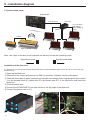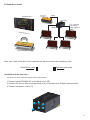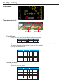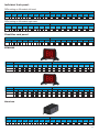
1
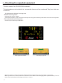
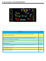
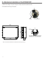
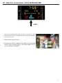
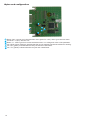
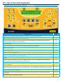
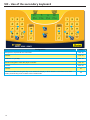
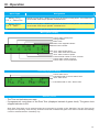
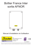
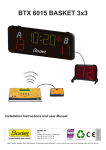
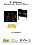
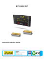
BTX 6220 WP
Installation and User Manual
www.bodet-sport.com
BODET SA
BP30001
49340 Trémentines I FRANCE
Tel: +33 241 71 72 00
Fax: +33 241 71 72 01
Réf : 607468H
This document is concerning the following product : BTX6220WP, ref: 915791.
Upon receipt, always check the product for damage during shipment. If any is found, you may file a damage claim with the carrier.
1
Table des matières
I - Checking the supplied equipment.....................................................................................................4
II - Description of the BTX6220 WP.......................................................................................................5
III - Mechanical installation of the BTX6220 WP...................................................................................6
IV - Electric connection of the BTX6220 WP.........................................................................................7
V - Installation diagram..........................................................................................................................8
VI - Dips setting....................................................................................................................................10
VII - Use of the main keyboard.............................................................................................................13
VIII - Use of the secondary keyboard...................................................................................................14
IX - Operation.......................................................................................................................................15
Electrical and mechanical safety standards
-
-
-
-
-
-
-
-
-
2
Installation and maintenance of this equipment should only be carried out by qualified and authorized personnel.
Since BT6000 scoreboards are connected to a 110/240VAC supply, they must be installed in compliance with standard IEC 364.
Indoor use (protected against mechanical shocks according to DIN18032.3 Standard).
The 110/240VAC supply line for the shot clock panel must include a neutral/phase circuit breaker, rapidly accessible. This circuit
breaker must be switched off during maintenance operations.
The installation must be completed before the equipment can be powered up.
It is prohibited and dangerous to immerse the scoreboard in to water or clean it with a water jet.
Installation ground connection as per EE or EN (earth/earth or earth/neutral) power supply diagram.
Bodet shall not be held responsible for any use not in compliance with these instructions.
Any modification to the product shall void the warranty.
3
I - Checking the supplied equipment
The kit is made of the BTX6220 WP scoreboard.
The keyboards are not included in the commercial reference of the scoreboard. They have their own
references.
The keyboards are delivered in a storage case.
- BT6000 main keyboard:
Delivered with a power adapter.
A secondary keyboard can be connected to this keyboard along with a start/stop hand-switch and a shot clock keyboard.
- Secondary keyboard fouls/points:
Powered by the main keyboard BT6000.
BTX6220 WP
Main keyboard BT6000
Secondary keyboard
Maximum distance for HF communication between the keyboard and the shot clock panels is 100 metres.
Make a provision for an electric outlet or an extension cord to allow for the recharging of the keyboard battery if its level
were to become insuffisant (full charge autonomy > 8 hours).
4
II - Description of the BTX6220 WP
A
B
K
H
K’
H’
E’
E
F
C
D
F’
D’
Designation
Label
Game clock - minutes-seconds (1/10 of second display during the last minute of the game).
Countdown timer between periods.
A
Game clock stopped indicator. Cluster lights up when the clock is stopped and between periods.
B
Number of the current period (E for Extra time).
C
Scores from 0 to 999 HOME/VISIT.
D & D’
Penalties indicators
E & E’
3 Time-out indicators HOME/VISIT (blinks when the timer is counting down). Reset of the time-out
indicators at the end of each period.
F & F’
Programmable teams’ names.
H & H’
Individual fouls HOME/VISIT.
K & K’
5
III - Mechanical installation of the BTX6220 WP
1/ Mount the casing on 2 posts using the 4 clamps and the threaded rods (D).
2/ Proceed to the wiring of the panel.
D
Clamp
Threaded rod
2080
C
1076
1130
R4,50
Tear drop holes for wall mounting
with Ø8 screws and wall anchors
C
1780
120 maxi
Note: to mount the scoreboard to a wall use the 4 tear drop holes C).
6
76
118
IV - Electric connection of the BTX6220 WP
A
Most of the BTX6220 WP cabling is done at the factory. These
instructions deal with the cabling to be done during the installation
at the customer site.
A
1/Open all the access doors.
2/Connect the 240V + earth power cable to the terminal
block of the BTX6220 WP(A). (the power cable (3x1,5²)
is not supplied by BODET).
7
V - Installation diagram
1/ Synchronised mode
BTX6220 WP
T+/T- (2 wires)
Horn box
T+/T- (2 wires)
Low voltage
power supply (2
wires)
Mains
RS485
Shot clock
keyboard
Main keyboard
Note : the 3 dips of the shot clock keyboard can be set to select the operating mode:
Stand-alone mode
Synchronised mode
Installation of the horn box:
It is possible to synchronise the BT6002 WP and the main scoreboard BT6000 (game clock and 30 sec shot clock stop
simutaneously).
1/ Open up the black box.
2/ Disconnect the 4 wires and remove the DIN (A) connector. Replace it by the cable gland.
3/ Feed the Data cable (2 wires) coming from the main scoreboard (D) through the gland and connect
it on the terminal block (E) (white wire RT+ and brown wire RT-) of the electronic card inside the
black box.
4/ Close the black box.
5/ Connect the BTX6002WP 30 sec shot clocks to the (B) plugs of the black box.
6/ Connect the power cord to (C).
D
A
C
8
B
B
B
B
E
2/ Stand-alone mode
Shot clock
keyboard
BTX6220 WP
RS485
Horn box
Mains
T+/T- (2 wires)
Low voltage
power supply (2
wires)
Main keyboard
Note : the 3 dips of the shot clock keyboard can be set to select the operating mode:
Stand-alone mode
Synchronised mode
Installation of the horn box :
The 30sec shotclock keyboard operates then independently.
1/ Connect each BTX6002 WP to the black box in (B).
2/ Connect the 30 sec shot clock keyboard to (A) of the black box: RS485 communication.
3/ Connect the power cord to (C).
A
C
B
B
B
B
9
VI - Dips setting
BTX6220WP
Central panel card:
First DIP bank
Second DIP bank
First DIP bank:
- Dips 1 to 4 are used for the factory setting of the panel.
Dip 1
Dip 2
Dip 3
Dip4
on ↑
on ↑
off ↓
off ↓
- Dips 5 to 7 are used to set the panel number (if several panels are to be controlled on
the same site, each panel needs to have its own number).
- Dip 8 is in the position ON.
Pannel number
Dip 5
Dip 6
Dip 7
1
off ↓
on ↑
on ↑
2
on ↑
off ↓
on ↑
3
off ↓
off ↓
on ↑
4
on ↑
on ↑
off ↓
5
off ↓
on ↑
off ↓
6
on ↑
off ↓
off ↓
Second DIP bank :
- Dips 1 to 3 are used to determined the installation number.
- Dips 4 to 8 are not used.
10
Installation number
Dip 1
Dip 2
Dip 3
1
off ↓
on ↑
on ↑
2
on ↑
off ↓
on ↑
3
off ↓
off ↓
on ↑
4
on ↑
on ↑
off ↓
5
off ↓
on ↑
off ↓
6
on ↑
off ↓
off ↓
Individual fouls panel:
DIPs setting on 20-module left card:
Row 1
Dip 1
on ↑
Dip 2
on ↑
Dip 3
off ↓
Dip 4
on ↑
Row 2
Dip 5
off ↓
Dip 6
off ↓
Dip 7
off ↓
Dip 8
on ↑
Dip 9
off ↓
Dip 10 Dip 11 Dip 12 Dip 13 Dip 14 Dip 15 Dip 16
on ↑
on ↑
off ↓
off ↓
off ↓
off ↓
off ↓
DIPs setting on 20-module right card:
Row 1
Dip 1
off ↓
Dip 2
off ↓
Dip 3
on ↑
Dip 4
on ↑
R2
Dip 5
off ↓
Dip 6
off ↓
Dip 7
off ↓
Dip 8
on ↑
Dip 9
off ↓
Dip 10 Dip 11 Dip 12 Dip 13 Dip 14 Dip 15 Dip 16
on ↑
on ↑
off ↓
off ↓
off ↓
off ↓
off ↓
Penalities card panel:
Row 1
Dip 1
on ↑
Dip 2
off ↓
Dip 3
on ↑
Dip 4
on ↑
Row 2
Dip 5
off ↓
Dip 6
off ↓
Dip 7
off ↓
Dip 8
on ↑
Dip 9
off ↓
Dip 10 Dip 11 Dip 12 Dip 13 Dip 14 Dip 15 Dip 16
on ↑
on ↑
off ↓
off ↓
off ↓
off ↓
off ↓
BTX6002
Row 1
Mode
Row 2
Dip 1 Dip 2 Dip 3 Dip 4 Dip 5 Dip 6 Dip 7 Dip 8 Dip 9 Dip 10 Dip 11 Dip 12 Dip 13 Dip 14 Dip 15 Dip 16
Synchronised
on ↑
on ↑
on ↑
off ↓
on ↑
off ↓
on ↑
on ↑
off ↓
off ↓
off ↓
off ↓
off ↓
off ↓
off ↓
off ↓
Standalone
on ↑
on ↑
on ↑
off ↓
on ↑
on ↑
on ↑
on ↑
off ↓
off ↓
off ↓
off ↓
off ↓
off ↓
off ↓
off ↓
Row 1
Mode
Row 2
Dip 1 Dip 2 Dip 3 Dip 4 Dip 5 Dip 6 Dip 7 Dip 8 Dip 9 Dip 10 Dip 11 Dip 12 Dip 13 Dip 14 Dip 15 Dip 16
Synchronised
on ↑
on ↑
on ↑
off ↓
on ↑
on ↑
on ↑
on ↑
off ↓
off ↓
off ↓
off ↓
off ↓
off ↓
off ↓
off ↓
Standalone
on ↑
on ↑
on ↑
off ↓
on ↑
on ↑
on ↑
on ↑
off ↓
off ↓
off ↓
off ↓
off ↓
off ↓
off ↓
off ↓
Horn box
Row 1
Dip 1
on ↑
Dip 2
on ↑
Dip 3
on ↑
Dip 4
off ↓
Dip 5
on ↑
Row 2
Dip 6
on ↑
Dip 7
on ↑
Dip 8
on ↑
Dip 9
off ↓
Dip 10 Dip 11 Dip 12 Dip 13 Dip 14 Dip 15 Dip 16
off ↓
off ↓
off ↓
off ↓
off ↓
off ↓
off ↓
11
Alpha card configuration:
A
D
B
F
E
C
A Button «Sel»: used to get in the technician menu (press for 3 sec.) and to go to the next menu.
B Connector: +V (5V) / Ground / RT Button
«+»: used to get in the current technician menu or to change the value of the parameter.
C
D Led «RUN» (green, blinking): indicates that the card is powered and that the software is working.
Led
«Rx» (green): indicates that the card just received a data frame.
E
F Led «Tx» (yellow): indicates that the card just sent a data frame.
12
VII - Use of the main keyboard
Main keyboard
2
1
[
3
ý 13:34 &
ÿ
6
]
1/3
3
30
13
4
8
5
6
7
9
10
12
11
14
14’
12’
15
15’
Designation
Label
Pressing this key toggles between Game clock display or Time of Day clock display
1
Starts a new match when pressed for more than 3 sec.
2
Game clock reset: reloads the values programmed for the beginning of the match (the clock must be
stopped) without reseting the scores and fouls..
3
Go to next period..
4
Turn ON or OFF the horn. The horn will sounds as long as this key is pressed.
5
Starts the game clock
6
Stops the game clock.
7
Gives acces to the settings menu.
8
Correction mode: Pressing this key once causes the display to blink. After the corrections have been made,
press the key once to return to the normal mode.
9
Unused.
10
While in match mode: starts a new match if pressed formore than 3 sec. Stettings menu: validates the
settings and exit this menu and teturn to the match mode.
11
Assign the Home/Visit. time-outs. The time-out timers stop automatically when reaching 0 or when these
keys are pressed.
12 & 12’
Menus browsing keys. At the start of a sport: pressing the + and - modifies of the game time (in minutes).
13
Assign Home/Visit. 20 sec. penalties.
14 & 14’
Add one point to the Home/Visit. teams’ Score (these keys are inactive when a secondary keyboard is
connected).
15 & 15’
Adjustment of the scoreboards luminosity.
30
13
VIII - Use of the secondary keyboard
13
Pts
19
16
5
6
Fts
Fts
10
Pts
19’
21
17’
20
20’
16’
17’
22
18
18’
Designation
Label
Assigment of a personal foul Home/Visit.
16 & 16’
Unused.
17 & 17’
Validation of a penalty.
18 & 18’
Numerical keypad to enter the player’s number.
19 & 19’
Unused.
20 & 20’
Unused.
21
Correction mode: Pressing this key once causes the display to blink. After the corrections have been
made, press the key once to return to the normal mode.
22
14
IX - Operation
Sport Type
Designation
Water-Polo
1:4 x 8min+Tps
4 periods of 8 mn game - RESET of gma clock at the end of each period - 2 mn Rest Time
- 60 secondes Time Out per période - Automatic horn.
Water-Polo
2:4 x 8min
4 periods of 8 mn game - RESET of gma clock at the end of each period - 2 mn Rest Time
- 60 secondes Time Out per période - Automatic horn.
All these parameters can be modified with the specific program for each type of configuration.
Main keyboard display
20
[
ý
8:00 &
19ÿ
6 1/4
3 ]
“Home” team penalty timer.
Timing indicator.
Game clock.
Game clock stopped indicator.
Auto Horn indicator.
“Visit.” team penalty timer.
“Visit.” team Time Out indicator.
“Visit.” team number of points.
Current Period number or Time-out timer.
“Home” team number of points.
“Home” team Time Out indicator.
Secondary keyboard display
13
Pts
5
Fts
6
Fts
10
Pts
“Home” team Score.
Cumulative total of “Home” team’s fouls.
“Visit.” team Score.
Cumulative total of “Visit.” team’s fouls.
Between periods
- The Time-out indicators are reset.
- If programmed, count-down of the Rest Time (displayed instead of game clock). The game clock
stopped indicator is ON.
Nota: Rest Times timer can be stopped during the count-down by pressing on the “Start/Stop” key and Time Outs by
using the corresponding “Time Out” key. At the end of the the countdown the game clock does not restart automatically,
it must be restarted with the “Start/Stop” key.
15
Sport paramaters menu
The pre-recorded basic configuration of each sport can be modified. Select and validate a sport and a rule type. To enter
the setting menu of the sport press the SEL (8) for 3 sec.:
- Modify the value of each parameter with the + and - keys (13) .
- To go to the next parameter press the ► key (13).
- To go back to the previous parameter press the ◄ key (13).
- Press the OK key (11).
Type 1
Type 2
Parameters
Shot timer
duration
: 30 sec
30 sec
1 to 99 sec.
4
1 to 9
Period duration
/ game
:
8 min
8 min
1 to 90 min.
Selection of the duration of the periods.
Half time
duration
:
5 min
0 to 90 min.
Selection of the duration of the Half Time Break if different
from 5.
If = 0, no automatic Half Time.
Period number
/ game
:
4
5 min
Description
Time left for a team having the possession of the ball to
attempt a goal
Selection of the number of periods
Auto time break
duration
:
2 min
2 min
0 to 90 min.
If = 0, no automatic timing.
If > 0, the scoreboard will automatically countdown the
programmed duration at the end of the period.
Press “Stop” to stop the countdown.
Horn before time
brk end
:
5 sec
5 sec
0 to 999 sec.
If = 0, Auto horn disabled
If > 0, a brief honking of the horn to signals that the end of a
rest time is near. (between periods or half time).
Extra time
duration
:
3 min
0 to 90 min.
Selection of duration of the Extra time periods.
If = 0, no Extra time.
3
1 to 3
20 sec
0 to 60 sec.
Selection of the duration of the penalties (in sec/player).
60 sec
0 to 99 sec.
Selection of the duration of the Time Outs
Yes
Yes or No
Horn before time
out end
: 10 sec
0 sec
0 to 99 sec.
If = 0, auto horn disabled.
Si > 0, a brief honking of the horn to signals that the end of a
time out is near.
Keep display
result
:
30sec
+-30 sec
10 to 60 sec.
by steps
of 10 sec.
Selection of the time during which the last period data will stay
displayed if the automatic rest time is not programmed.
5 sec
0 to 5 sec
3 min
Individual foul
number
:
3
Penalty
duration
:
Time out
duration :
20 sec
60 sec
Auto horn time out
end : Yes
Horn
duration
16
:
5 sec
Selection of the maximum number of personal fouls before
exclusion.
If Yes, horn starts automatically at the end of each timeout.
If = 0, auto horn disabled.
If > 0, limits the duration of the horn blowing to reduce the
noise level.