1
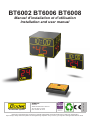
BT6002 BT6006 BT6008
BODET SA
BP30001
49340 Trémentines I France
www.bodet-sport.fr
Tél +33 241 71 72 99
Fax +33 247 29 77 41
Réf : 607125E
Manuel d’installation et d’utilisation
Installation and user manual
S’assurer à la réception que le produit n’a pas été endommagé durant le transport pour réserve au transporteur
Upon receipt, always check the product for damage during shipment. If any is found, you may file a damage claim with the carrier.1
Table des matières
I - Vérification du matériel fourni........................................................................................................................................... 3
II - Support mural à plat (uniquement pour BT 6002 et 6006).............................................................................................. 4
III - Paramétrage des dips.................................................................................................................................................... 4
IV - Fixation du montant sur panneau de basket pour BT 6002........................................................................................... 5
V - Branchement électrique BT6002.................................................................................................................................... 6
VI - Installation BT6002 HF autonome................................................................................................................................. 6
VII - Installation BT6002 Filaire autonome........................................................................................................................... 7
VIII - Fixation du montant sur panneau de basket pour BT 6006......................................................................................... 8
IX - Branchement électrique BT6006................................................................................................................................... 9
X - Fixation du montant sur panneau de basket BT6008.................................................................................................... 10
XI - Branchement électrique BT6008.................................................................................................................................. 11
XII - Liaison filaire (inutile en mode HF).............................................................................................................................. 12
Table of content
I - Checking the supplied material....................................................................................................................................... 14
II - Wall mounting (only BT6002 and 6006)......................................................................................................................... 15
III - DIP switches setting...................................................................................................................................................... 15
IV - Mounting behind basketball backboard (BT6002)........................................................................................................ 16
V - Electrical connections BT6002...................................................................................................................................... 17
VI - Installation BT6002 HF (Autonomous wireless)............................................................................................................ 17
VII - Installation BT6002 (Autonomous Wired).................................................................................................................... 18
VIII - Mounting behind basketball backboard (BT6006)...................................................................................................... 19
IX - Electrical connections BT6006..................................................................................................................................... 20
X - Mounting behind basketball backboard (BT6008)......................................................................................................... 21
XI - Electrical connections BT6008..................................................................................................................................... 22
XII - Wired connection (unused in HF mode)...................................................................................................................... 23
Normes de sécurité électriques et mécaniques
- L’installation et l’entretien de ce matériel doit être fait par du personnel habilité.
- Les tableaux d’affichage de la gamme BT6000 étant connectés à l’alimentation secteur, leur installation doit respecter la norme
IEC 364 (NFC 15.100 pour la France).
- Installation en intérieur (le panneau est protégé contre les chocs des ballons norme DIN 18032.3).
- L’alimentation secteur des tableaux d’affichage doit comporter un disjoncteur phase neutre, rapidement accessible en amont de la
ligne d’alimentation.
- Ce matériel doit être fixé avant sa mise sous tension.
- Il est interdit et dangereux d’immerger le tableau d’affichage ou de le nettoyer au jet.
- Raccordement de la terre sur installation selon le schéma TT ou TN (terre/terre ou terre/neutre).
- La société Bodet décline toute responsabilité en cas d’usage non conforme à la présente notice.
- Toute modification sur le produit entraîne la perte de la garantie.
Electrical and mechanical safety standards
- Installation and maintenance of this equipment should only be carried out by qualified and authorized personnel.
- Since BT6000 scoreboards are connected to a 110/240VAC supply, they must be installed in compliance with standard IEC 364.
- Indoor use (protected against mechanical shocks according to DIN18032.3 Standard).
- The 110/240VAC supply line for the shot clock panel must include a neutral/phase circuit breaker, rapidly accessible. This circuit
breaker must be switched off during maintenance operations.
- The installation must be completed before the equipment can be powered up.
- It is prohibited and dangerous to immerse the scoreboard in to water or clean it with a water jet.
- Installation ground connection as per EE or EN (earth/earth or earth/neutral) power supply diagram.
- Bodet shall not be held responsible for any use not in compliance with these instructions.
- Any modification to the product shall void the warranty.
2
I - Vérification du matériel fourni
I - Tableaux
- Chaque panneau est livré par paire.
II - Pupitres
Le pupitre est livré dans une valise de rangement.
- Pupitre temps de possession :
Livré avec 2 afficheurs temps de possession.
Alimenté par le pupitre principal.
BT6006
BT6008
BT6002
Pupitre temps de possession
Distance maximum pour la communication par commande HF entre le pupitre et le(s) tableau(x) est de 100 mètres.
3
II - Support mural à plat (uniquement pour BT 6002 et 6006)
Matériel fourni avec le kit de fixation murale :
- 2 profils en U.
- Vis TH M10x30.
- Écrous HU M10.
- Rondelles plates Ø10.
- Rondelles éventails Ø10.
1/Fixer les 2 profils en U sur l’afficheur à l’aide des vis TH M10x30, des écrous HU M10 et rondelles
plates Ø10 (voir A).
2/Fixer les 2 profils en U au mur en respectant les côtes de perçage (utiliser le gabarit fourni) (vis et
écrous M10 ne sont pas fournis par BODET).
Fixation au mur
Écrou HU M10
Rondelle éventail Ø10
Profil en U
Rondelle plate Ø10
581 mm
Vis TH M10x30
360 mm
Profil en U
III - Paramétrage des dips
Les dips sont paramétrés en usine, vérifier qu’ils sont bien paramétrés comme cidessous.
1/Ouvrir les trappes de chaque panneau. Pour ouvrir chaque porte il faut
dévisser d’un quart de tour les 2 vis de chaque porte.
2/Les dips 1 à 4 servent à identifier le type d’élément du panneau que
commande la carte.
3/Les dips 5 à 8 servent à numéroter chaque panneau.
AUCUN TABLEAU NE DOIT AVOIR LE MÊME NUMÉRO.
Vis quart de tour
BT 6006
BT 6002
BT 6008
4
N° panneau
Dip 5
Dip 6
Dip 7
1
off ↓
on ↑
on ↑
2
on ↑
off ↓
on ↑
3
off ↓
off ↓
on ↑
4
on ↑
on ↑
off ↓
5
off ↓
on ↑
off ↓
6
on ↑
off ↓
off ↓
IV - Fixation du montant sur panneau de basket pour BT 6002
Matériel fourni avec le kit de fixation panier réf. 915870 (pour chaque afficheur 24 sec.) :
- 1 montant - 1 sabot - 2 profils en U - Contreplaque
- Tiges filetée M10x185 - Vis H M10 x 90 - Écrous HU M10 frein - Rondelles plates Ø12
- Boulons M10x90 - Vis H M10x50 - Rondelles plates Ø10
330mm
581 mm
1/Suivant le type de panneau de basket, mettre à longueur le montant (tube 60 × 30) du support de
chaque afficheur afin de respecter la position finale (distance réglementaire des dimensions L).
2/ Fixer le sabot avec les 4 tiges filetées + rondelles plates et contreplaque sur le bras du panneau.
3/ Fixer les 2 profils en U sur le montant (positionnement différent suivant modèle).
4/Positionner le montant dans sabot avec vis HM10×90, écrou HU M10 frein et rondelle plate Ø10.
5/ Pivoter à la verticale le montant, puis le bloquer avec 1 vis HM10×90, 1 écrou HU M10 frein et
rondelle plate Ø10, dans la lumière du sabot.
6/ Fixer l’afficheur au montant à l’aide des boulons H M10x30, les écrous HU M10 frein, les rondelles
plates Ø12 et les rondelles dec Ø10.
7/ Vérifier les dimensions L (de 30 à 50 cm). Contre percer au Ø11 le tube en position définitive puis
bloquer avec une vis HM10×90 traversant le tube, 1 écrou HU M10 frein et rondelle plate Ø10.
Écrou HU M10 frein
Axe de pivot
A
Vis HM10x90
Rondelle plate Ø10
Découpe du montant
A
Découpe du montant
Vis M10x50
Écrou HU M10 frein
Tige filetée M10 long. 185
Rondelle plate Ø10
Bras du panneau de basket
(tube carré de 100 à 140).
Contre percer le tube au Ø11 en position verticale
pour maintenir l’afficheur en position fixe et définitive.
A l’aide d’une vis H M10x90 et 1 écrou HU M10 frein.
Écrou HU M10 frein
5
V - Branchement électrique BT6002
A
A
1/Ouvrir toutes les trappes d’accès.
2/Raccorder l’alimentation 230 V sur le bloc alimentation (A) en faisant passer les fils par le trou
prévu à cet effet, et attacher les câbles électriques au châssis ceci pour éviter toute traction sur les
borniers (le cable secteur (3x1,5²) n’est pas fourni par BODET).
3/Les dips sont paramétrés en usine. Vérifier qu’ils sont bien paramétrés (voir page 5).
VI - Installation BT6002 HF autonome
1/Brancher le pupitre temps de possession sur la prise DIN du boîtier autonome.
2/ Brancher les alimentations secteur de chaque BT6002 et du boîtier autonome.
Secteur 240V
Secteur 240V
BT6002 HF autonome
Boîtier autonome
Secteur
240V
BT6002 HF autonome
Pupitre temps de
possession
Pour poser les afficheurs au
sol fixer le support à l’arrière du
BT6002 avec les 2 vis
Les dips sont paramétrés en usine, vérifier qu’ils sont bien paramétrés comme ci-dessous.
1/Ouvrir les trappes de chaque panneau. Pour ouvrir chaque porte il faut dévisser les 2 vis de
chaque porte.
2/Les dips 1 à 4 sont toujours vers le bas.
3/Les dips 5 à 8 sont toujours vers le haut ON ↑.
6
VII - Installation BT6002 Filaire autonome
1/Brancher le pupitre temps de possession sur la prise DIN du câble de dérivation.
2/Brancher chaque BT6002 sur les 2 autres extrémités du câble de dérivation.
3/ Brancher les alimentations secteur de chaque BT6002.
Nota 1 : le klaxon est présent uniquement sur un des deux afficheurs BT6002.
Nota 2 : Les câbles de commande vers les 2 afficheurs BT6002 sont de longueur différentes (voir schéma ci-dessous).
Fusible
BT6002
Vers secteur 230V
BT6002
câble de
dérivation
Pupitre temps de possession
Vers secteur 230V
Câ
ble
Pour poser les afficheurs au
sol fixer le support à l’arrière
du BT6002 avec les 2 vis
de
33
m
Câble de
20m
7
VIII - Fixation du montant sur panneau de basket pour BT 6006
Matériel fourni avec le kit de fixation panier réf. 915870 (pour chaque afficheur 24 sec.) :
- 1 montant - 1 sabot - 2 profils en U - Contreplaque
- Tiges filetée M10x185 - Vis H M10 x 90 - Écrous HU M10 frein - Rondelles plates Ø12
- Boulons M10x90 - Vis H M10x50 - Rondelles plates Ø10
581 mm
1/Suivant le type de panneau de basket, mettre à longueur le montant (tube 60 × 30) du support de
chaque afficheur afin de respecter la position finale (distance réglementaire des dimensions L).
2/ Fixer le sabot avec les 4 tiges filetées + rondelles plates et contreplaque sur le bras du panneau.
3/ Fixer les 2 profils en U sur le montant (positionnement différent suivant modèle).
4/Positionner le montant dans sabot avec vis HM10×90, écrou HU M10 frein et rondelle plate Ø10.
5/ Pivoter à la verticale le montant, puis le bloquer avec 1 vis HM10×90, 1 écrou HU M10 frein et
rondelle plate Ø10, dans la lumière du sabot.
6/ Fixer l’afficheur au montant à l’aide des boulons H M10x30, les écrous HU M10 frein, les rondelles
plates Ø12 et les rondelles dec Ø10.
7/ Vérifier les dimensions L (de 30 à 50 cm). Contre percer au Ø11 le tube en position définitive puis
bloquer avec une vis HM10×90 traversant le tube, 1 écrou HU M10 frein et rondelle plate Ø10.
Écrou HU M10 frein
Axe de pivot
A
Vis HM10x90
Rondelle plate Ø10
Découpe du montant
A
Découpe du montant
Vis M10x50
Écrou HU M10 frein
Tige filetée M10 long. 185
Rondelle plate Ø10
Écrou HU M10 frein
8
Bras du panneau de basket
(tube carré de 100 à 140).
Contre percer le tube au Ø11 en position verticale
pour maintenir l’afficheur en position fixe et définitive.
A l’aide d’une vis H M10x90 et 1 écrou HU M10 frein.
IX - Branchement électrique BT6006
A
A
1/Ouvrir toutes les trappes d’accès.
2/Raccorder l’alimentation 230 V au bornier (A) en faisant passer les fils par le trou prévu à cet effet,
et attacher les câbles électriques au châssis ceci pour éviter toute traction sur les borniers (le cable
secteur (3x1,5²) n’est pas fourni par BODET).
3/Les dips sont paramétrés en usine. Vérifier qu’ils sont bien paramétrés (voir page 5).
9
X - Fixation du montant sur panneau de basket BT6008
Matériel fourni avec le kit de fixation panier réf. 915870 (pour chaque afficheur 24 sec.) :
- 1 montant - 1 sabot - 2 profils en U - Contreplaque
- Tiges filetée M10x185 - Vis H M10 x 90 - Écrous HU M10 frein - Rondelles plates Ø12
- Boulons M10x90 - Vis H M10x50 - Rondelles plates Ø10
1/Suivant le type de panneau de basket, mettre à longueur le montant (tube 60 × 30) du support de
chaque afficheur afin de respecter la position finale (distance réglementaire des dimensions L).
2/ Fixer le sabot avec les 4 tiges filetées + rondelles plates et contreplaque sur le bras du panneau.
3/ Fixer les 2 profils en U sur le montant (positionnement différent suivant modèle).
4/Positionner le montant dans sabot avec vis HM10×90, écrou HU M10 frein et rondelle plate Ø10.
5/ Pivoter à la verticale le montant, puis le bloquer avec 1 vis HM10×90, 1 écrou HU M10 frein et
rondelle plate Ø10, dans la lumière du sabot (A).
6/ Fixer l’afficheur au montant à l’aide des boulons H M10 x 60, les écrous HU M10 frein, les rondelles
plates Ø10 et les rondelles Ø10 (B).
7/ Vérifier les dimensions L (de 30 à 50 cm). Contre percer au Ø11 le tube en position définitive puis
bloquer avec une vis HM10×90 traversant le tube, 1 écrou HU M10 frein et rondelle plate Ø10.
B
Axe de pivot
A
A
Découpe du montant
A
A
Découpe du montant
B
Vis HM10x90
Rondelle plate Ø10
Tige filetée M10 long. 185
Rondelle plate Ø10
Bras du panneau de basket
(tube carré de 100 à 140).
Contre percer le tube au Ø11 en position verticale
pour maintenir l’afficheur en position fixe et définitive.
A l’aide d’une vis H M10x90 et 1 écrou HU M10 frein.
B
10
plate Ø10
Rondelle
dents Ø10
Rondelle à
Écrou HU M10
Écrou HU M10 frein
Boulon HM10 x 60
Écrou HU M10 frein
XI - Branchement électrique BT6008
A
A
Terre
Phase
Neutre
1/Ouvrir toutes les trappes d’accès.
2/Raccorder l’alimentation 230 V au bornier (A) en faisant passer les fils par le trou prévu à cet effet,
et attacher les câbles électriques au châssis ceci pour éviter toute traction sur les borniers (le cable
secteur (3x1,5²) n’est pas fourni par BODET).
3/Les dips sont paramétrés en usine. Vérifier qu’ils sont bien paramétrés (voir page 5).
A
11
XII - Installation de l’entourage LED rouge et du bandeau LED
jaune
Entourage LED rouge (réf: 915896)
1/ Fixer les six tubes de l’entourage LED rouge via les pattes de fixation sur le panneau de basket.
2/Faire la connection des borniers de chaque élément de l’entourage LED rouge entre eux (A).
Laisser un bornier libre (B).
3/Brancher le câble avec connecteur de 4m fourni (fils provenant du BT6006-60081) sur le bornier
resté libre (B).
Bandeau LED jaune (réf: 915898)
1/ Fixer les deux tubes du bandeau LED jaune via les pattes de fixation sur l’entourage LED rouge.
2/Faire la connection des borniers de chaque élément du bandeau lumineux entre eux (C). Laisser
un bornier libre (D).
3/Brancher le câble avec connecteur de 4m fourni (fils provenant du BT6006-60081) sur le bornier
resté libre (D).
A
A
lg. 800
lg. 800
D
lg. 800
lg. 800
C
lg. 500
A
A
lg. 500
B
A
Disposition tubes de l’entourage LED rouge et du bandeau LED jaune
Pattes de fixation
lg. 800
A
D
A
C
Le câblage interne du BT6006-6008 est réalisé dans nos ateliers. Pour une identification simple et
rapide lors de l’installation (branchements), les fils sont étiquettés.
1
12
XIII - Liaison filaire (inutile en mode HF)
A
A
BT6000
A
V+
A
GND
1/ Pour une installation avec un ou plusieurs tableaux, brancher un
câble télécom 1 paire 9/10 RT+ et RT- (C) sur chaque tableau.
Brancher l’autre extrémité du câble au boîtier de raccordement
(A). Débrancher le câble modem si nécessaire. Respecter les
polarités.
2/ Refermer les trappes d’accès et allumer le(s) tableau(x).
RT+
Pupitre principal
RT-
Vers autres
tableaux
si nécessaire
A
13
Fonctionnement normal du pupitre temps de possession
1/Un appui sur la touche START / STOP (1) démarre le décompte du chronomètre du temps de possession.
Un nouvel appui sur cette touche permet un arrêt de ce chronomètre.
Lorsque que le temps de possession est écoulé (= 0), un signal sonore 4
3
se déclenche pendant une durée de 3 secondes.
5
7
6
La LED du pupitre est rouge lorsque le temps de possession est
arrêté et en vert lorsque le temps de possession est en décompte.
1
2
8
2/Un appui prolongé sur la touche RESET 24s (2) ou RESET 14s (8)
du pupitre temps de possession provoque une mise au noir du tableau
temps de possession et une mise au noir de la visu. Lors du relâchement,
le chronomètre temps de possession reprend sa valeur initiale de 24 sec ou 14 sec selon la touche.
3/Un appui sur la touche EFFACE (3) (la visu affiche - - provoque une mise au noir du panneau temps de
possession. Un nouvel appui sur cette touche permet le ré-affichage de la valeur en cours de décompte,
sans modification de l’état du chronomètre temps de possession.
4/Un appui sur la touche KLAXON (4) provoque l’arrêt du klaxon lancé automatiquement à la fin du temps de
possession. Cette touche ne permet pas d’activer le klaxon.
Modification du temps de possession en cours
1/Arrêter le chronomètre temps de possession avec la touche START / STOP (1).
2/Appuyer sur la touche CORRECTION (6) du pupitre temps de possession.
La visu du pupitre, la led du pupitre ainsi que le panneau se mettent à clignoter.
3/Chaque appui sur la touche PLUS + (5) incrémente de 1 seconde le temps de possession en cours.
Cette valeur ne peut pas dépasser la valeur du RESET (2) mémorisée (par défaut 24 secondes).
4/Chaque appui sur la touche MOINS - (7) du pupitre temps de possession décrémente de 1 seconde le temps
de possession en cours.
5/Appuyer de nouveau sur CORRECTION (6) pour revenir en mode normal.
Récupération du temps de possession
1/Dans le cas d’un appui accidentel sur la touche RESET (2) pendant le décompte du temps de possession,
il est possible de récupérer l’ancien temps de possession par un appui sur la touche EFFACE (3) dans les 2
secondes suivant l’appui sur la touche RESET (2).
Modification de la valeur du RESET mémorisée (par défaut 24 sec)
1/Arrêter le chronomètre temps de possession avec la touche START / STOP (1).
2/Faire un appui prolongé de 3 secondes sur la touche CORRECTION (6).
La visu du pupitre de possession et le panneau 24 sec se mettent à clignoter. La valeur affichée correspond
à la valeur du RESET en cours.
3/Chaque appui sur la touche PLUS + (5) incrémente de 1 seconde la valeur du RESET (2) en cours. Cette
valeur ne peut pas dépasser 99 secondes.
4/Chaque appui sur la touche MOINS - (7) décrémente de 1 seconde la valeur du RESET (2) en cours.
5/Appuyer de nouveau sur CORRECTION (6) pour revenir en mode normal.
Pas de sauvegarde de ce paramètre si coupure de courant ou lors du débranchement du pupitre à la fin du match.
Réglage de la luminosité du panneau d’affichage BT6002
1/Appui 3 secondes sur la touche + (5) du pupitre temps de possession. La visu affiche le niveau actuel de
luminosité de 1 à 5.
2/Appui sur la touche + (5) du pupitre temps de possession pour augmenter la luminosité.
3/Appui sur la touche - (7) du pupitre temps de possession pour diminuer la luminosité.
4/Valider avec la touche C (6) du pupitre temps de possession.
Pas de sauvegarde de ce paramètre si coupure de courant ou lors du débranchement du pupitre à la fin du match.
14
I - Checking the supplied material
I - Scoreboard
- Each model is shipped as a pair.
II - Keyboard
The keyboard is shipped in a carrying case.
- Shot clock keyboard (Time Pad) :
Supplied with the 2 shot clock panels
The Time Pad Synchro keyboard which connects to and is powered by the BT6000 main keyboard.
BT6006
BT6008
BT6002
Timepad keyboard
Maximum distance for HF communication between the keyboard and the shot clock panels is 100 metres.
15
II - Wall mounting (only BT6002 and 6006)
For each 24 second display, the mounting kit is supplied with :
- 2 mounting brackets
- TH M10x30 screws
- HU M10 nuts
- Ø10 flat washers
- Ø10 lock washers
1/Mount the 2 brackets to the display with TH M10x30 screws, HU M10 bolts and Ø10 washers
(see A).
2/Mount the 2 brackets to the wall while respecting the drilling measurement (use the provided
template) (M10 screws and nuts are not suplied by BODET).
Wall mounting
TH M10x30 screw
HU M10 nut
581 mm
Ø10 flat washers
Ø10 lock washer
360 mm
mounting bracket
mounting brackets
III - DIP switches setting
DIP switches have been set in factory; please check that they are set as follows.
1/Open all the access hatches. To open the access doors, unscrew the
quarter-turn screws.
2/DIP switches n°1 to 4 define the part of scoreboard.
3/DIP switches n°5 to 8 define the scoreboard number.
EACH SCOREBOARD MUST HAVE A DIFFERENT NUMBER.
Quarter-turn screw
BT 6006
BT 6002
BT 6008
16
Scoreboard N°
Dip 5
Dip 6
Dip 7
1
off ↓
on ↑
on ↑
2
on ↑
off ↓
on ↑
3
off ↓
off ↓
on ↑
4
on ↑
on ↑
off ↓
5
off ↓
on ↑
off ↓
6
on ↑
off ↓
off ↓
IV - Mounting behind basketball backboard (BT6002)
For each BT6002, the mounting kit is supplied with :
- 1 support mast
- 1 shoe
- M10x185 threaded shafts
- H M10 x 90 screws
- M10x90 bolts
- H M10x50 screws
- 2 U sections
- HU M10 nuts
- Ø10 flat washers
- Ø12 flat washers
- back plate
581 mm
1/According to the type of basketball boards, extend the support mast (60 × 30 tube) for each display
until it reaches the final position (regulation distance for dimensions L).
2/Fix the shoe with 4 threaded shafts + flat washers and backplate to the beam of the basketball board
(See D).
3/Fix the 2 U sections to the mast (level depending on model).
4/Position the mast in the shoe with 1 HM10×90 screw, 1 HU M10 nut and Ø10 flat washer.
5/Rotate the mast vertically, then lock it with a HM10×90 screw, 1 HU M10 nut and Ø10 flat washer to
the opening of the shoe.
6/Fix the display to the mast with H M10x30 bolts, HU M10 nuts, Ø12 flat washers and Ø10 washers.
7/Check the distance L (30 to 50 cm). Once the panel is in the right position, drill all the way through
the mast tube (Ø11) and fit in a HM10×90 screw, 1 HU M10 lock nut and Ø10 flat washer to hold the
panel in its final vertical position.
HU M10 nut
M10x50 screw
A
HM10x90 screw
Cut the tube
Pivot axis
Cut the tube
A
Ø10 flat washer
HU M10 nuts
M10x185 threaded shaft
Ø10 flat washer
HU M10 nuts
Basketball backboard arm
(100 to 140 square tube).
Drill through the tube to Ø11 in the vertical position
to hold the display unit in the fixed and final position.
With 1x H M10x90 screw and 1x HU M10 nut.
17
V - Electrical connections BT6002
A
A
1/Open the access door of each BT6002.
2/Connect 240V power + Earth to the power supply terminal (A) by passing the cable through the hole
provided for this purpose and attach the cable to the housing to avoid any traction on the terminal
(this 240V power cable is not supllied by BODET).
3/DIP switches have been set in factory. Check the position of the DIP switches for the 2 BT6002 (see
page 7).
VI - Installation BT6002 HF (Autonomous wireless)
1/Connect the shot clock keyboard to the DIN plug of the autonomous box.
2/ Connect the power to each BT6002 and to the autonome box.
240V
240V
BT6002 HF autonomous
autonomous
box
240V
BT6002 HF autonomous
Shot clock
keyboard
To use the panels standing on
the ground,mount the bracket
on the back of the panel
The dip switches are set at the factory, check that they are set as follow.
1/Open the access door of each panel.
2/Dip switches 1 to 4 always OFF.
3/Dip switches 5 to 8 always ON ↑.
18
VII - Installation BT6002 (Autonomous Wired)
1/Connect the shot clock keyboard to the DIN plug of the spliting cable.
2/Connect each BT6002 at the other ends of the spliting cable.
3/ Connect the power cords of the BT6002.
Nota 1 : The horn is present on only one BT6002 panel.
Nota 2 : The control cables of the 2 BT6002 are of different length. (see illustration).
Fuse
BT6002
230V AC
BT6002
Spliting
cable
Shot clock keyboard
230V AC
33
m
ca
ble
le
To use the panels standing on
the ground,mount the bracket
on the back of the panel
20m cab
19
VIII - Mounting behind basketball backboard (BT6006)
For each BT6006, the mounting kit is supplied with :
- 1 support mast
- 1 shoe
- M10x185 threaded shafts
- H M10 x 90 screws
- M10x90 bolts
- H M10x50 screws
- 2 U sections
- HU M10 nuts
- Ø10 flat washers
- Ø12 flat washers
- Back plate
581 mm
1/According to the type of basketball boards, extend the support mast (60 × 30 tube) for each display
until it reaches the final position (regulation distance for dimensions L).
2/Fix the shoe with 4 threaded shafts + flat washers and back plate to the beam of the basketball
board (See D).
3/Fix the 2 U sections to the mast (level depending on model).
4/Position the mast in the shoe with 1 HM10×90 screw, 1 HU M10 nut and Ø10 flat washer.
5/Rotate the mast vertically, then lock it with a HM10×90 screw, 1 HU M10 nut and Ø10 flat washer to
the opening of the shoe.
6/Fix the display to the mast with H M10x30 bolts, HU M10 nuts, Ø12 flat washers and Ø10 washers.
7/Check the distance L (30 to 50 cm). Once the panel is in the right position, drill all the way through
the mast tube (Ø11) and fit in a HM10×90 screw, 1 HU M10 lock nut and Ø10 flat washer to hold the
panel in its final vertical position.
HU M10 nut
M10x50 screw
A
HM10x90 screw
Cut the tube
Pivot axis
Cut the tube
A
Ø10 flat washer
HU M10 nuts
M10x185 threaded shaft
Ø10 flat washer
HU M10 nuts
20
Basketball backboard arm
(100 to 140 square tube).
Drill through the tube to Ø11 in the vertical position
to hold the display unit in the fixed and final position.
With 1x H M10x90 screw and 1x HU M10 nut.
IX - Electrical connections BT6006
A
1/Open the access door of each BT6006.
2/Connect 240V power + Earth to the power supply terminal (A) by passing the cable through the hole
provided for this purpose and attach the cable to the housing to avoid any traction on the terminal
(this 240V power cable is not supllied by BODET).
3/DIP switches have been set in factory. Check the position of the DIP switches for the 2 BT6006 (see
page 7).
21
X - Mounting behind basketball backboard (BT6008)
For each 24 second display, the mounting kit is supplied with :
- 1 support mast
- 1 shoe
- M10x185 threaded shafts
- H M10 x 90 screws
- M10x90 bolts
- H M10x50 screws
- 2 U sections
- HU M10 nuts
- Ø10 flat washers
- Ø12 flat washers
- plywood
1/According to the type of basketball boards, extend the support mast (60 × 30 tube) for each display
until it reaches the final position (regulation distance for dimensions L).
2/Fix the shoe with 4 threaded shafts + flat washers and plywood to the beam of the basketball board
(See D).
3/Fix the 2 U sections to the mast (level depending on model).
4/Position the mast in the shoe with 1 HM10×90 screw, 1 HU M10 nut and Ø10 flat washer.
5/Rotate the mast vertically, then lock it with a HM10×90 screw, 1 HU M10 nut and Ø10 flat washer to
the opening of the shoe.
6/Fix the display to the mast with H M10x60 bolts, HU M10 nuts, Ø10 flat washers and Ø10 washers
(B).
7/Check the distance L (30 to 50 cm). Once the panel is in the right position, drill all the way through
the mast tube (Ø11) and fit in a HM10×90 screw, 1 HU M10 lock nut and Ø10 flat washer to hold the
panel in its final vertical position.
B
B
A
A
Cut the tube
Pivot axis
Cut the tube
A
A
HM10x90 screw
Ø10 flat washer
HU M10 nuts
M10x185 threaded shaft
Ø10 flat washer
Basketball backboard arm
(100 to 140 square tube).
Drill through the tube to Ø11 in the vertical position
to hold the display unit in the fixed and final position.
With 1x H M10x90 screw and 1x HU M10 nut.
B
22
H M10x60 bolt
Ø10 flat washer
Ø10 flat washer
U M10 Nut
HU M10 nuts
XI - Electrical connections BT6008
A
Earth
Phase
Neutral
1/Open the access door of each BT6006.
2/Connect 240V power + Earth to the power supply terminal (A) by passing the cable through the hole
provided for this purpose and attach the cable to the housing to avoid any traction on the terminal
(this 240V power cable is not supllied by BODET).
3/DIP switches have been set in factory. Check the position of the DIP switches for the 2 BT6008 (see
page 6).
A
23
XII - Installation backboard perimeter red LED strip and yellow
LED strip
Backboard perimeter red LED strip (ref: 915896)
1/ Install the tubes of the backboard perimeter LED strip on the inside borders of the backboard using
the square brackets.
2/ Connect the tubes together (A). Leave one connector free (B).
3/ Connect the 4-m cable supplied (shot clock wires1) to the free connector (B).
Yellow LED strip (ref: 915898)
1/ Install two tubes of yellow LED strip with the brackets on the backboard perimeter LED strip.
2/ Connect the tubes together (C). Leave one connector free (D).
3/ Connect the 4-m cable supplied (shot clock wires1) to the free connector (D).
A
A
lg. 800
lg. 800
D
lg. 800
lg. 800
C
lg. 500
A
A
lg. 500
B
A
Provision tubes environment backboard perimeter red LED strip and yellow LED strip
Square brackets
lg. 800
A
D
A
C
The internal cabling of the shot clock is realized in our factory. For a simple and fast identification
during the installation (connections), the wires are connected.
1
24
XIII - Wired connection (unused in HF mode)
A
A
BT6006
BT6000
To other
scoreboards
if necessary
BT6006
A
Main keyboard
V+
GND
RT+
A
RT-
1/For an installation with one or several boards, connect a telephone
cable 1 pair 0.9 mm RT+ and RT- (B) on every board. And connect
the other side of the cable to the connection box (A). Disconnect
the modem cable if necessary. Respect polarity.
2/Close the access doors and switch on the scoreboard.
A
25
Normal operation of the shot clock keyboard
1/Press START / STOP (1) to satrt the countdown of the shot clock. Press again to stop the countdown.
At the end of the countdown (when the possession time reaches 0)
a sounding signal is started for a duration of 3 seconds.
4
6
3
The LED of the keyboard turns red when the shot clock is stopped
5
7
and green when the shot clock is counting down.
2/Pressing the RESET 24s (2) or RESET 14s (8) key for few seconds
1
2
8
causes the shot clock LED panel and the LCD display of the keyboard
to turn off (blank). The initial value of the timer (24 sec or 14 sec
depending on which key was pressed) is restored when the key is released.
3/Pressing the CLEAR (3) key causes the keyboard LCD display to show - - and the shot clock panel to blank.
Pressing this key again allows the displaying of the current countdown value without affecting the running of
the timer.
4/Pressing the HORN (4) stops the horn when its is blown automatically when the countdown reaches 0.
This key does not turn on the horn.
Modify the current possession time
1/Press the START / STOP (1) key to stop the timer.
2/Press the C (6) key.
The LCD display and the led of the keyboard start blinking.
3/Press the PLUS + (5) key to increment by 1 second the current possession time.
This value cannot exceed the stored RESET value (24 sec by default).
4/Press the MINUS - (7) key to décement by 1 second the current possession time.
5/Press the C (6) key again to go back to the normal mode.
Recover possession time
1/If the RESET 24s (2) key is pressed by mistake then press the CLEAR (3) key within the following
2 seconds to recover the previous time.
Modify the preset value of the possession time (default: 24 seconds)
1/Press the START / STOP (1) key to stop the possession time timer..
2/Hold down the CORRECTION (6) key of the possession time keyboard for 3 seconds.
The Shot clock displays and the keyboard LCD display are blinking. The value displayed is the currentRESET value.
3/Press the + (5) key to increment the current RESET value (99 sec. max.).
4/Press the - (7) key to decrement the current RESET value.
5/Press the CORRECTION (6) key to come back to normal model.
This parameter is not saved in case of a power failure or if the keyboard is unplug at the end of the game.
Luminosity adjustment of BT6002 display
1/Press the + (5) key during 3 seconds.
2/Press the + (5) key to increase the luminosity.
3/Press the - (7) key to decrease the luminosity.
4/Press the C (6) key to go back to normal mode.
No backup of this parameter, if the power is cut or when unplugging the keyboard at the end of the match.
26