1
MP2200/MP2300 Machine Controller
Motion Module User’s Manual
Model: JAPMC-MC2310/JAPMC-MC2300
Copyright © 2002 YASKAWA ELECTRIC CORPORATION
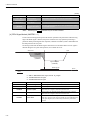
All rights reserved. No part of this publication may be reproduced, stored in a retrieval system,
or transmitted, in any form, or by any means, mechanical, electronic, photocopying, recording,
or otherwise, without the prior written permission of Yaskawa. No patent liability is assumed
with respect to the use of the information contained herein. Moreover, because Yaskawa is constantly striving to improve its high-quality products, the information contained in this manual is
subject to change without notice. Every precaution has been taken in the preparation of this
manual. Nevertheless, Yaskawa assumes no responsibility for errors or omissions. Neither is
any liability assumed for damages resulting from the use of the information contained in this
publication.
Using this Manual
Please read this manual to ensure correct usage of the SVB-01 Module of MP2200/MP2300.
Keep this manual in a safe place for future reference.
Basic Terms
Unless otherwise specified, the following definitions are used:
• SVA-01:
Motion Module SVA-01
• SVB-01:
Motion Module SVB-01
• MP2200/MP2300: Machine Controller MP2200/MP2300
• SVR:
Virtual Motion Module SVR
• PC:
Programmable Logic Controller
• PP:
Programming Panel
• MPE720:
The Programming Device Software or a Programming Device (i.e., a
personal
computer) running the Programming Device Software
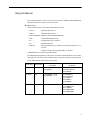
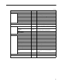
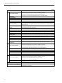
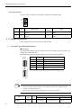
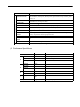
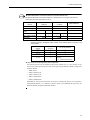
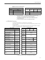
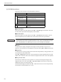
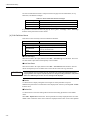
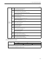
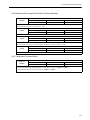
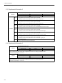
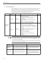
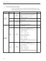
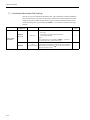
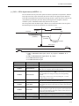
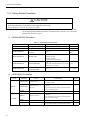
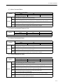
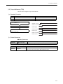
• SERVOPACK Series Names and Abbreviations
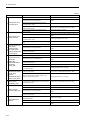
The SERVOPACKS applicable to the SVA-01 and SVB-01 Motion Modules are listed in the
following table. The series names and abbreviations used in this manual are limited to those
for the SERVOPACK model numbers listed below.
Series Name
Abbreviation
SERVOPACKs Applicable to
the SVB-01
SERVOPACKs Applicable to
the SVA-01
Σ Series
Σ
SGD-N,
SGDB-AN
SGDA-S,
SGDB-AD-,
SGDB-DD
Σ-II Series
Σ-II
SGDH-E + NS100,
SGDH-E + NS115
SGDM-DA,
SGDM-AD,
SGDH-DE,
SGDH-AE,
SGDH-E
Σ-III Series
Σ-III
SGDS-1
SGDS--01,
SGDS--02,
SGDS-05,
SGDS-A,
SGDS-F
iii
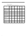
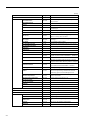
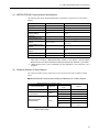
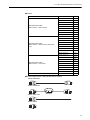
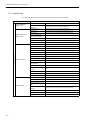
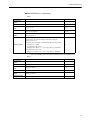
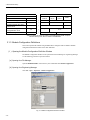
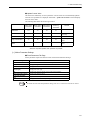
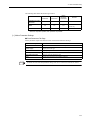
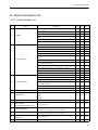
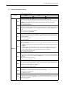
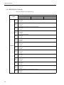
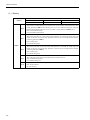
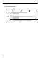
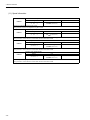
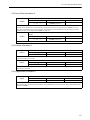
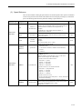
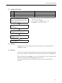
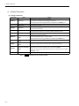
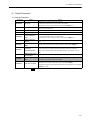
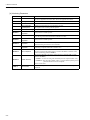
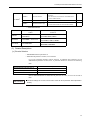
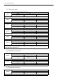
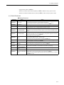
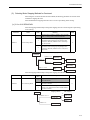
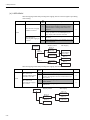
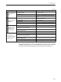
Manual Configuration
Read the chapters of this manual as required by the purpose.
Chapter
iv
Selecting
Studying
Designing
Models and Specifications the System
Peripheral
and Ratings
Devices
Installation
and Wiring
Trial
Maintenance
Operation
and
Inspection
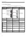
Chapter 1
Motion Module Overview
Applicable
−
−
−
−
−
Chapter 2
Module Specifications and
Connections
Applicable
Applicable
Applicable
Applicable
−
−
Chapter 3
Motion Module Setup
Applicable
−
Applicable
−
Applicable
−
Chapter 4
Motion Parameters
−
−
Applicable
−
Applicable
−
Chapter 5
Motion Commands
−
−
Applicable
−
Applicable
Applicable
Chapter 6
Control Block Diagrams
−
−
Applicable
−
Applicable
Applicable
Chapter 7
Absolute Position
Detection
−
−
Applicable
−
Applicable
Applicable
Chapter 8
SVR Virtual Motion
Module
−
−
Applicable
−
Applicable
−
Chapter 9
Utility Functions
Applicable
−
Applicable
−
Applicable
Applicable
Chapter 10
Troubleshooting
−
−
−
−
Applicable
Applicable
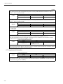
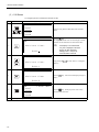
Visual Aids
The following aids are used to indicate certain types of information for easier reference.
IMPORTANT
INFO
EXAMPLE
TERMS
Indicates important information that should be memorized.
Indicates supplemental information.
Indicates application examples.
Describes technical terms that are difficult to understand, or appear in the text without an
explanation being given.
Indication of Reverse Signals
In this manual, the names of reverse signals (ones that are valid when low) are written with a
forward slash
(/) before the signal name, as shown in the following example:
• S-ON
= /S-ON
• P-CON
= /P-CON
v
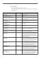
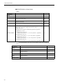
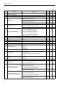
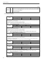
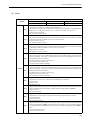
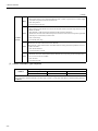
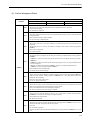
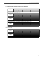
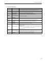
Related Manuals
Refer to the following related manuals as required.
Thoroughly check the specifications, restrictions, and other conditions of the product before
attempting to use it.
Manual Name
Machine Controller MP2200
User’s Manual
Machine Controller MP2300
Basic Module User’s Manual
Machine Controller MP2300
Communication Module User’s Manual
Manual Number
SIEPC88070014
Machine Controller MP900/MP2000 Series
User’s Manual
MECHATROLINK System
SIEZ-C887-5.1
Machine Controller MP900 Series
User's Manual
Ladder Programming
Machine Controller MP9
User's Manual
Motion Programming
SIEZ-C887-1.2
Describes the instructions used in MP900/MP2000 ladder
programming.
SIEZ-C887-1.3
Describes the instructions used in MP900/MP2000 motion
programming.
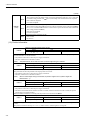
Machine Controller MP900/MP2000 Series
User’s Manual
MPE720 Software for Programming Device
Σ Series SGM/SGD
User’s Manual
Σ Series SGM/SGDB
User’s Manual
SIEPC88070005
Describes how to install and operate the MP900/MP2000
Series programming system (MPE720).
SIE-S800-26.3
Describes the Σ Series SERVOPACK models, specifications and capacity selection methods.
SIE-S800-26.4
Σ Series SGM/SGDA
User's Manual
TSE-S800-15
Σ Series SGMB/SGDB
User's Manual
SIE-S800-16.1
Σ Series SGM/SGDB
User's Manual
TSE-S800-16.1
Σ-II Series SGMH/SGDH
User’s Manual
Design and Maintenance
SIEPS80000005
Describes the models, capacities, selection methods, ratings, characteristics, diagrams, cables, peripheral devices,
wiring, panel installation, trial operation, adjustment, function application methods, maintenance, inspection, and
MECHATROLINK communication of the Σ Series SERVOPACKs and Servomotors.
Describes the models, capacities, selection methods, ratings, characteristics, diagrams, cables, peripheral devices,
wiring, panel installation, trial operation, adjustment, function application methods, maintenance, and inspection of
the Σ Series SERVOPACKs and Servomotors.
Describes the models, capacities, selection methods, ratings, characteristics, diagrams, cables, peripheral devices,
wiring, panel installation, trial operation, adjustment, function application methods, maintenance, and inspection of
the Σ Series SERVOPACKs and Servomotors.
Describes the models, capacities, selection methods, ratings, characteristics, diagrams, cables, peripheral devices,
wiring, panel installation, trial operation, adjustment, function application methods, maintenance, and inspection of
the Σ Series SERVOPACKs and Servomotors.
Describes the models, capacities, selection methods, ratings, characteristics, diagrams, cables, peripheral devices,
wiring, panel installation, trial operation, adjustment, function application methods, maintenance, and inspection of
the Σ-II Series SERVOPACKs and Servomotors.
vi
SIEPC88070003
SIEPC88070004
Contents
Describes the design and maintenance of the MP2200
Machine Controller.
Describes the design and maintenance of the MP2300 Basic
Module.
Describes the functions, specifications, and application
methods of the MP2300 Communication Modules (217IF,
218IF, 260IF, 261IF).
Describes the communication functions, specifications, and
application methods of the MECHATROLINK Modules for
MP900 Machine Controllers.
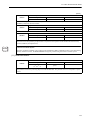
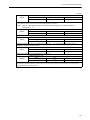
(cont’d)
Manual Name
Manual Number
SIE-C718-4
Contents
Describes the MECHATROLINK-I communication method
using the JUSP-NS100 application module installed on the
Σ-II Series SERVOPACK.
Σ-II Series SGDH
MECHATROLINK-II Application Module
User’s Manual
SIEPC71080001
Describes the MECHATROLINK-II communication
method using the JUSP-NS115 application module installed
on the Σ-II Series SERVOPACK.
Σ-II Series SGMH/SGDM
User's Manual
SIEPS80000015
Σ-III Series SGMS/SGDS
User’s Manual
For MECHATROLINK-II Communications
SIEPS80000011
Σ-III Series SGMS/SGDS
User's Manual
SIEP80000000
Linear Σ Series SGL/SGDS
User's Manual
SIEPS80000016
Machine Controller MP900 Series
New Ladder Editor
Programming Manual
Machine Controller MP900 Series
New Ladder Editor
User’s Manual
SIE-C887-13.1
Describes the models, capacities, selection methods, ratings, characteristics, diagrams, cables, peripheral devices,
wiring, panel installation, trial operation, adjustment, function application methods, maintenance, and inspection of
the Σ-II Series SERVOPACKs and Servomotors.
Describes the models, capacities, selection methods, ratings, characteristics, diagrams, cables, peripheral devices,
wiring, panel installation, trial operation, adjustment, function application methods, maintenance, inspection, and
MECHATROLINK communication of the ∑-III Series
SERVOPACKs and Servomotors.
Describes the models, capacities, selection methods, ratings, characteristics, diagrams, cables, peripheral devices,
wiring, panel installation, trial operation, adjustment, function application methods, maintenance, and inspection of
the Σ-III Series SERVOPACKs and Servomotors.
Describes the models, capacities, selection methods, ratings, characteristics, diagrams, cables, peripheral devices,
wiring, panel installation, trial operation, adjustment, function application methods, maintenance, and inspection of
the Σ-III Series SERVOPACKs and Linear Servomotors.
Describes the programming instructions of the New Ladder
Editor, which assists MP900/MP2000 Series design and
maintenance.
Describes the operating methods of the New Ladder Editor,
which assists MP900/MP2000 Series design and maintenance.
Σ-II Series SGDH
MECHATROLINK Interface Unit
User’s Manual
SIE-C887-13.2
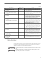
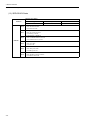
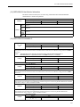
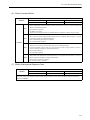
Safety Information
The following conventions are used to indicate precautions in this manual. Failure to heed
precautions provided in this manual can result in serious or possibly even fatal injury or
damage to the products or to related equipment and systems.
WARNING
Indicates precautions that, if not heeded, could possibly result in loss of life or serious
injury.
CAUTION
Indicates precautions that, if not heeded, could result in relatively serious or minor
injury, damage to the product, or faulty operation.
vii
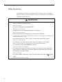
Safety Precautions
The following precautions are for checking products on delivery, storage, transportation,
installation, wiring, operation, maintenance, inspection, and disposal. These precautions are
important and must be observed.
WARNING
• Before starting operation in combination with the machine, ensure that an emergency stop procedure
has been provided and is working correctly.
There is a risk of injury.
• Do not touch anything inside the MP2200/MP2300.
There is a risk of electrical shock.
• Always keep the front cover attached when power is being supplied.
There is a risk of electrical shock.
• Observe all procedures and precautions given in this manual for trial operation.
Operating mistakes while the servomotor and machine are connected can cause damage to the machine or even
accidents resulting in injury or death.
• Do not remove the front cover, cables, connector, or options while power is being supplied.
There is a risk of electrical shock.
• Do not damage, pull on, apply excessive force to, place heavy objects on, or pinch cables.
There is a risk of electrical shock, operational failure or burning of the MP2200/MP2300.
• Do not attempt to modify the MP2200/MP2300 in any way.
There is a risk of injury or device damage.
• Do not approach the machine when there is a momentary interruption to the power supply. When
power is restored, the machine may start operation suddenly. Provide suitable safety measures to
protect people when operation restarts.
There is a risk of injury.
• Do not allow installation, disassembly, or repairs to be performed by anyone other than specified personnel.
There is a risk of electrical shock or injury.
viii
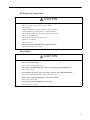
Storage and Transportation
CAUTION
• Do not store or install the MP2200/MP2300 in the following locations.
There is a risk of fire, electrical shock, or device damage.
• Direct sunlight
• Ambient temperature exceeds the storage or operating conditions
• Ambient humidity exceeds the storage or operating conditions
• Rapid changes in temperature or locations subject to condensation
• Corrosive or flammable gas
• Excessive dust, dirt, salt, or metallic powder
• Water, oil, or chemicals
• Vibration or shock
• Do not overload the MP2200/MP2300 during transportation.
There is a risk of injury or an accident.
Installation
CAUTION
• Never use the MP2200/MP2300 in locations subject to water, corrosive atmospheres, or flammable
gas, or near burnable objects.
There is a risk of electrical shock or fire.
• Do not step on the MP2200/MP2300 or place heavy objects on the MP2200/MP2300.
There is a risk of injury.
• Do not block the air exhaust port or allow foreign objects to enter the MP2200/MP2300.
There is a risk of element deterioration inside, an accident, or fire.
• Always mount the MP2200/MP2300 in the specified orientation.
There is a risk of an accident.
• Do not subject the MP2200/MP2300 to strong shock.
There is a risk of an accident.
ix
Wiring
CAUTION
• Check the wiring to be sure it has been performed correctly.
There is a risk of motor run-away, injury, or an accident.
• Always use a power supply of the specified voltage.
There is a risk of burning.
• In places with poor power supply conditions, take all steps necessary to ensure that the input power
supply is within the specified voltage range.
There is a risk of device damage.
• Install breakers and other safety measure to provide protection against shorts in external wiring.
There is a risk of fire.
• Provide sufficient shielding when using the MP2200/MP2300 in the following locations.
There is a risk of device damage.
• Noise, such as from static electricity
• Strong electromagnetic or magnetic fields
• Radiation
• Near to power lines
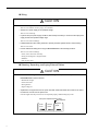
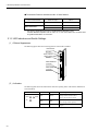
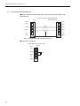
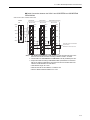
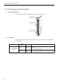
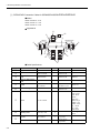
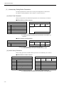
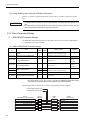
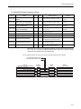
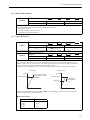
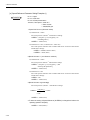
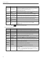
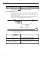
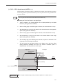
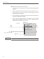
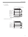
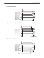
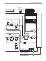
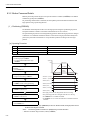
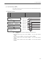
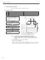
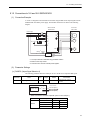
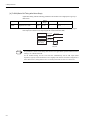
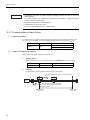
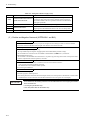
Selecting, Separating, and Laying External Cables
CAUTION
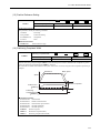
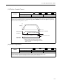
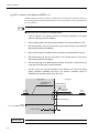
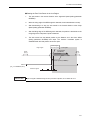
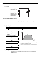
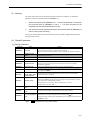
• Consider the following items when selecting the I/O signal lines (external cables) to connect the
MP2200/MP2300 to external devices.
• Mechanical strength
• Noise interference
• Wiring distance
• Signal voltage, etc.
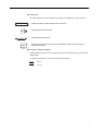
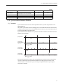
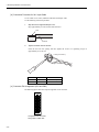
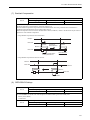
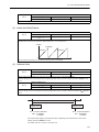
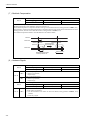
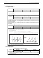
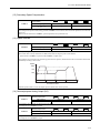
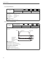
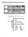
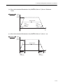
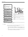
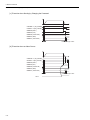
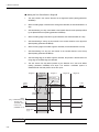
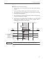
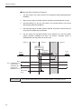
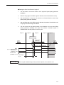
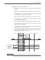
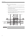
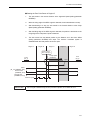
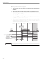
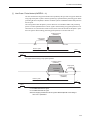
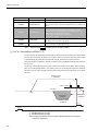
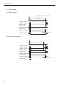
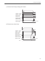
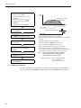
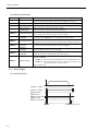
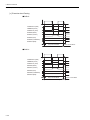
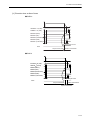
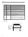
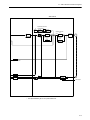
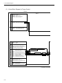
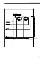
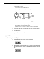
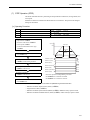
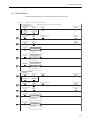
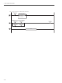
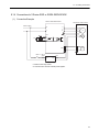
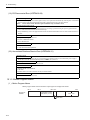
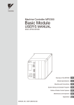
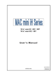
• Separate the I/O signal lines from the power lines both inside and outside the control box to reduce
the influence of noise from the power lines.
If the I/O signal lines and power lines are not separated properly, malfunctioning may result.
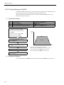
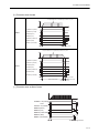
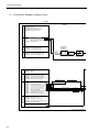
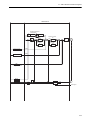
Example
of Separated External Cables
外部配線の分離例
Steel
separator
鉄板製のセパレータ
x
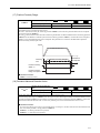
Power
General
Digital I/O
circuit
動力回路の
一般制御回路
control
signal
入出力信号
ケーブル
のケーブル
ディジタル
ケーブル
Maintenance and Inspection
CAUTION
• Do not attempt to disassemble the MP2200/MP2300.
There is a risk of electrical shock or injury.
• Do not change wiring while power is being supplied.
There is a risk of electrical shock or injury.
• When replacing the MP2200/MP2300, restart operation only after transferring the programs and
parameters from the old Module to the new Module.
There is a risk of device damage.
Disposal
CAUTION
• Dispose of the MP2200/MP2300 as general industrial waste.
xi
xii
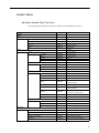
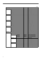
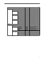
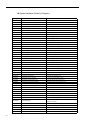
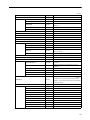
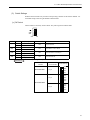
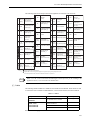
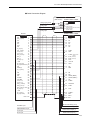
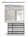
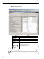
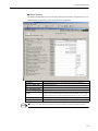
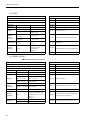
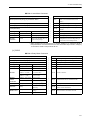
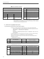
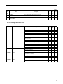
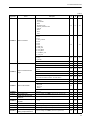
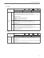
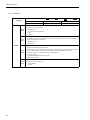
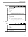
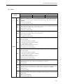
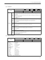
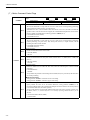
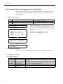
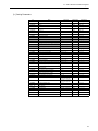
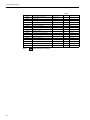
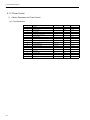
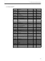
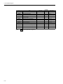
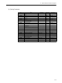
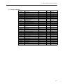
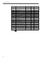
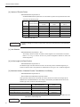
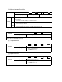
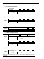
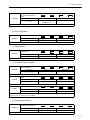
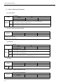
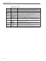
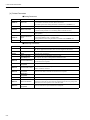
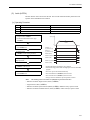
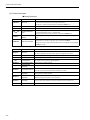
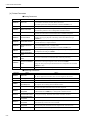
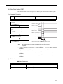
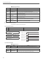
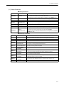
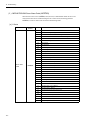
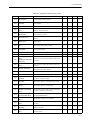
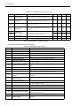
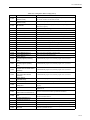
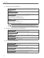
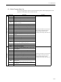
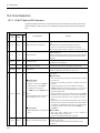
Variable Tables
System Variable Table (Tree View)
The following table lists details on the system variables provided by MPE720 version 6..
Variable Name
OnCoil
Clock
Register
Comments
SB000004
Always ON
-
Calendar
DayOfWeek
SW00019
Calendar:Day of week
HoursMinutes
SW00017
Calendar:Hours Minutes
MonthDate
SW00016
Calendar:Month Day
Second
SW00018
Calendar:Seconds
SW00015
Calendar:Year
-
Controller
Year
CPU
Error
-
CPU Error Status
SB000413
Exception Error
Failure
SB000410
Important Failure
IOError
SB000419
I/O Error
Exception
ProgramError
Info
SB000418
User Calculation Error
-
CPU Information
MemorySizeAvailable
SL00026
Available PRG Memory (BYTE)
MemorySizeTotal
SL00028
All Module Memory (BYTE)
SoftwareVersion
Status
SW00020
System Program Software Number
-
CPU Status
Alarm
SB000402
ALARM (1=Warning,0=Normal)
BatteryAlarm
SB000487
Battery Alarm (1=Alarm)
Error
SB000403
ERROR (1=Unusual,0=Normal)
Ready
SB000400
READY (1=Normal,0=Converse/Own
Diagnose Unusual)
Running
SB000401
RUN (1=Driving,0=Driving Stop)
RunSwitch
SB00040F
RUN switch status at power is on
(1=RUN,0=STOP)
Stopped
SB00040E
Running Stop Require
(From EWS:1=STOP,0=RUN)
WriteEnable
SB000407
WEN (Write:1=Possible,0=Impossible)
WritingToFlash
SB000406
FLASH (1=FLASH Driving)
-
CPU Switch
Switches
Configure
SB000482
CNFG (0=ON,1=OFF)
Initialize
SB000483
INIT (0=ON,1=OFF)
Stop
SB000485
STOP (0=ON,1=OFF)
-
High-Speed Program Error
Code
SW00085
High-Speed Program Error Code
Count
SW00084
High-Speed Program Error Count
ProgramNumber
SW00154
Error Program Number
ReferProgramNumber
SW00155
Function Program Number
ReferStep
SW00156
Function Program Step Number
ErrorHigh
xiii
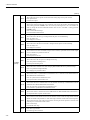
(cont’d)
Variable Name
ErrorInterrupt
Comments
-
Interrupt Program Error
Code
SW00083
Interrupt Program Error Code
Count
SW00082
Interrupt Program Error Count
ProgramNumber
SW00138
Error Program Number
ReferProgramNumber
SW00139
Function Program Number
ReferStep
SW00140
Function Program Step Number
-
I/O Error
Count
SW00200
I/O Error Count
ErrorIO
InputAddress
SW00202
Input Error Address
InputCount
SW00201
Input Error Times
OutputAddress
SW00204
Output Error Address
OutputCount
SW00203
Output Error Times
-
Low-Speed Program Error
ErrorLow
Code
SW00089
Low-Speed Program Error Code
Count
SW00088
Low-Speed Program Error Count
ProgramNumber
SW00186
Error Program Number
ReferProgramNumber
SW00187
Function Program Number
SW00189
Function Program Step Number
ReferStep
ErrorStart
-
Start Program Error
Code
SW00081
Start Program Error Code
Count
SW00080
Start Program Error Count
ProgramNumber
SW00122
Error Program Number
ReferProgramNumber
SW00123
Function Program Number
ReferStep
SW00124
Function Program Step Number
-
High Scan Relay
FirstScanRunning
SB000001
After High Scan Start,Only 1 Scan ON
OnAfter
-
Start-up Relay
SB00001A
After 5.0s,Scan Start-up Relay
HighScan
FiveSecond
OneSecond
SB000018
After 1.0s,Scan Start-up Relay
TwoSecond
SB000019
After 2.0s,Scan Start-up Relay
-
Sampling Relay
HalfSecond
SB000014
0.5s Sampling Relay
PulseEvery
OneMinute
SB000017
60.0s Sampling Relay
OneSecond
SB000015
1.0s Sampling Relay
TwoSecond
SB000016
2.0s Sampling Relay
-
Flicker Relay
SquareWave
xiv
Register
HalfSecond
SB000011
0.5s Flicker Relay
OneScan
SB000010
1 Scan Flicker Relay
OneSecond
SB000012
1.0s Flicker Relay
TwoSecond
SB000013
2.0s Flicker Relay
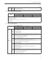
(cont’d)
Variable Name
LowScan
FirstScanRunning
OnAfter
Register
Comments
-
Low Scan Relay
SB000003
After Low Scan Start,Only 1 Scan ON
-
Start-up Relay
FiveSecond
SB00003A
After 5.0s,Scan Start-up Relay
OneSecond
SB000038
After 1.0s,Scan Start-up Relay
TwoSecond
SB000039
After 2.0s,Scan Start-up Relay
-
Sampling Relay
HalfSecond
SB000034
0.5s Sampling Relay
OneMinute
SB000037
60.0s Sampling Relay
OneSecond
SB000035
1.0s Sampling Relay
SB000036
2.0s Sampling Relay
PulseEvery
TwoSecond
SquareWave
-
Flicker Relay
HalfSecond
SB000031
0.5s Flicker Relay
OneScan
SB000030
1 Scan Flicker Relay
OneSecond
SB000032
1.0s Flicker Relay
TwoSecond
SB000033
2.0s Flicker Relay
-
Scan Time
ExecutionCurrentValue
SW00014
Execution Scan Current Value (0.1ms)
High
-
High Scan
ScanTime
CurrentValue
SW00005
High Scan Current Value (0.1ms)
ExceededCount
SW00044
High Scan Over Counter
MaximumValue
SW00006
High Scan Maximum Value (0.1ms)
SetValue
Low
SW00004
High Scan Set Value (0.1ms)
-
Low Scan
CurrentValue
SW00011
Low Scan Current Value (0.1ms)
MaximumValue
SW00012
Low Scan Maximum Value (0.1ms)
SetValue
SW00010
Low Scan Set Value (0.1ms)
ExceededCount
SW00046
Low Scan Over Counter
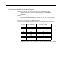
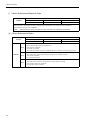
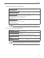
xv
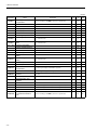
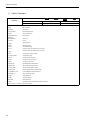
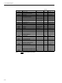
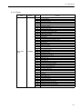
System Variables (Sorted by Register)
Register
xvi
Variable Name
Comments
SB000001
HighScan.FirstScanRunning
After High Scan Start,Only 1 Scan ON
SB000003
LowScan.FirstScanRunning
After Low Scan Start,Only 1 Scan ON
SB000004
OnCoil
Always ON
SB000010
HighScan.SquareWave.OneScan
1 Scan Flicker Relay
SB000011
HighScan.SquareWave.HalfSecond
0.5s Flicker Relay
SB000012
HighScan.SquareWave.OneSecond
1.0s Flicker Relay
SB000013
HighScan.SquareWave.TwoSecond
2.0s Flicker Relay
SB000014
HighScan.PulseEvery.HalfSecond
0.5s Sampling Relay
SB000015
HighScan.PulseEvery.OneSecond
1.0s Sampling Relay
SB000016
HighScan.PulseEvery.TwoSecond
2.0s Sampling Relay
SB000017
HighScan.PulseEvery.OneMinute
60.0s Sampling Relay
SB000018
HighScan.OnAfter.OneSecond
After 1.0s,Scan Start-up Relay
SB000019
HighScan.OnAfter.TwoSecond
After 2.0s,Scan Start-up Relay
SB00001A
HighScan.OnAfter.FiveSecond
After 5.0s,Scan Start-up Relay
SB000030
LowScan.SquareWave.OneScan
1 Scan Flicker Relay
SB000031
LowScan.SquareWave.HalfSecond
0.5s Flicker Relay
SB000032
LowScan.SquareWave.OneSecond
1.0s Flicker Relay
SB000033
LowScan.SquareWave.TwoSecond
2.0s Flicker Relay
SB000034
LowScan.PulseEvery.HalfSecond
0.5s Sampling Relay
SB000035
LowScan.PulseEvery.OneSecond
1.0s Sampling Relay
SB000036
LowScan.PulseEvery.TwoSecond
2.0s Sampling Relay
SB000037
LowScan.PulseEvery.OneMinute
60.0s Sampling Relay
SB000038
LowScan.OnAfter.OneSecond
After 1.0s,Scan Start-up Relay
SB000039
LowScan.OnAfter.TwoSecond
After 2.0s,Scan Start-up Relay
SB00003A
LowScan.OnAfter.FiveSecond
After 5.0s,Scan Start-up Relay
SW00004
ScanTime.High.SetValue
High Scan Set Value (0.1ms)
SW00005
ScanTime.High.CurrentValue
High Scan Current Value (0.1ms)
SW00006
ScanTime.High.MaximumValue
High Scan Maximum Value (0.1ms)
SW00010
ScanTime.Low.SetValue
Low Scan Set Value (0.1ms)
SW00011
ScanTime.Low.CurrentValue
Low Scan Current Value (0.1ms)
SW00012
ScanTime.Low.MaximumValue
Low Scan Maximum Value (0.1ms)
SW00014
ScanTime.ExecutionCurrentValue
Execution Scan Current Value (0.1ms)
SW00015
Clock.Year
Calendar:Year
SW00016
Clock.MonthDate
Calendar:Month Day
SW00017
Clock.HoursMinutes
Calendar:Hours Minutes
SW00018
Clock.Second
Calendar:Seconds
SW00019
Clock.DayOfWeek
Calendar:Day of week
SW00020
CPU.Info.SoftwareVersion
System Program Software Number
SL00026
CPU.Info.MemorySizeAvailable
Available PRG Memory (BYTE)
SL00028
CPU.Info.MemorySizeTotal
All Module Memory (BYTE)
SB000400
CPU.Status.Ready
READY (1=Normal,0=Converse/Own
Diagnose Unusual)
SB000401
CPU.Status.Running
RUN (1=Driving,0=Driving Stop)
SB000402
CPU.Status.Alarm
ALARM (1=Warning,0=Normal)
SB000403
CPU.Status.Error
ERROR (1=Unusual,0=Normal)
SB000406
CPU.Status.WritingToFlash
FLASH (1=FLASH Driving)
SB000407
CPU.Status.WriteEnable
WEN (Write:1=Possible,0=Impossible)
(cont’d)
Register
Variable Name
Comments
SB00040E
CPU.Status.Stopped
Running Stop Require
(From EWS:1=STOP,0=RUN)
SB00040F
CPU.Status.RunSwitch
RUN switch status at power is on (1=RUN,0=STOP)
SB000410
CPU.Error.Failure
Important Failure
SB000413
CPU.Error.Exception
Exception Error
SB000418
CPU.Error.ProgramError
User Calculation Error
SB000419
CPU.Error.IOError
I/O Error
SW00044
ScanTime.High.ExceededCount
High Scan Over Counter
SW00046
ScanTime.Low.ExceededCount
Low Scan Over Counter
SB000482
CPU.Switches.Configure
CNFG (0=ON,1=OFF)
SB000483
CPU.Switches.Initialize
INIT (0=ON,1=OFF)
SB000485
CPU.Switches.Stop
STOP (0=ON,1=OFF)
SB000487
CPU.Status.BatteryAlarm
Battery Alarm (1=Alarm)
SW00080
ErrorStart.Count
Start Program Error Count
SW00081
ErrorStart.Code
Start Program Error Code
SW00082
ErrorInterrupt.Count
Interrupt Program Error Count
SW00083
ErrorInterrupt.Code
Interrupt Program Error Code
SW00084
ErrorHigh.Count
High-Speed Program Error Count
SW00085
ErrorHigh.Code
High-Speed Program Error Code
SW00088
ErrorLow.Count
Low-Speed Program Error Count
SW00089
ErrorLow.Code
Low-Speed Program Error Code
SW00122
ErrorStart.ProgramNumber
Error Program Number
SW00123
ErrorStart.ReferProgramNumber
Function Program Number
SW00124
ErrorStart.ReferStep
Function Program Step Number
SW00138
ErrorInterrupt.ProgramNumber
Error Program Number
SW00139
ErrorInterrupt.ReferProgramNumber
Function Program Number
SW00140
ErrorInterrupt.ReferStep
Function Program Step Number
SW00154
ErrorHigh.ProgramNumber
Error Program Number
SW00155
ErrorHigh.ReferProgramNumber
Function Program Number
SW00156
ErrorHigh.ReferStep
Function Program Step Number
SW00186
ErrorLow.ProgramNumber
Error Program Number
SW00187
ErrorLow.ReferProgramNumber
Function Program Number
SW00189
ErrorLow.ReferStep
Function Program Step Number
SW00200
ErrorIO.Count
I/O Error Count
SW00201
ErrorIO.InputCount
Input Error Times
SW00202
ErrorIO.InputAddress
Input Error Address
SW00203
ErrorIO.OutputCount
Output Error Times
SW00204
ErrorIO.OutputAddress
Output Error Address
xvii
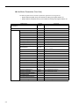
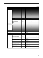
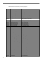
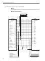
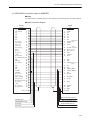
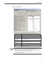
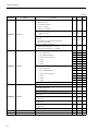
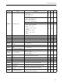
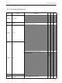
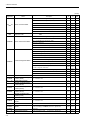
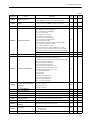
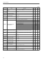
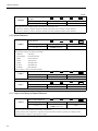
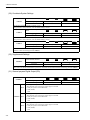
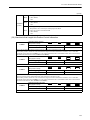
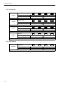
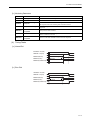
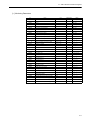
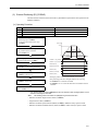
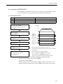
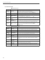
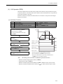
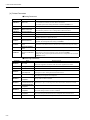
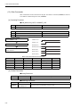
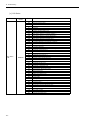
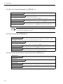
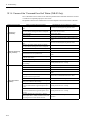
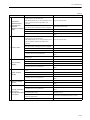
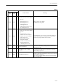
Axis Motion Parameters (Tree View)
The following table lists the axismotion parameters registered for each logical axis.
Register address IW (IB/IL/IF/IA) xx00 indicates the leading input register address +00.
Register address OW (OB/OL/OF/OA) xx00 indicates the leading output register address +00.
Variable Name
Acceleration
Alarm
xviii
Register
Comments
OLxx36
Acceleration Value, units selected by UnitsWord
(OWxx03)
-
Alarm
ABSEncoderOverrange
IBxx053
Absolute encoder number of rotations exceeded alarm
Active
IBxx2C0
Servo status ALM
Code
IWxx2D
Servo Alarm Code
AllMask
ILxx04
Alarm mask
Clear
OBxx00F
Clears servo alarms.
FilterTimeChanged
IBxx04B
Filter time constant changed while in motion alarm
FilterTypeChanged
IBxx04A
Filter type changed while in motion alarm
FollowingError
IBxx049
Following error exceeded alarm
HomingWhileMoving
IBxx04E
Zero point set while in motion alarm
MonitorNumber
OWxx4F
This value determines which of the last 10 alarm
codes are returned.
NegativeOvertravel
IBxx041
Positive overtravel alarm
NegativeSoftLimit
IBxx044
Negative software limit alarm
NegativeSoftLimitN
IBxx2CD
Servo status N SOT
NetworkServo
IBxx040
Servo alarm
NotHomed
IBxx04D
Zero point not set alarm
OutOfRangeParameter
IWxx01
Parameter number that is over range
PositionCompletionTimeOut
IBxx046
Positioning timeout alarm
PositionValueOutOfRange
IBxx047
Positioning out of range alarm
PositiveOvertravel
IBxx042
Negative overtravel alarm
PositiveSoftLimit
IBxx043
Positive software limit alarm
PositiveSoftLimitN
IBxx2CC
Servo status P SOT
ServoCommandTimeout
IBxx052
Servo command timeout alarm
ServoCommunication
IBxx051
Servo communication alarm
ServoCommunicationTimeout
IBxx050
Servo communication synchronization alarm
ServoNotEnabled
IBxx045
Servo OFF alarm
ServoParameterOutOfRange
IBxx04F
Servo parameter alarm
SpeedOutOfRange
IBxx048
Speed out of range alarm
(cont’d)
Variable Name
Command
Register
Comments
-
Command
Abort
OBxx091
Abort command
Busy
IBxx090
Servo command busy
Complete
IBxx098
Servo command complete
Fail
IBxx093
Servo command failed
GetValue
IWxx08
Servo command response
Hold
IBxx091
Servo command holding
JogRelativeMoveDirection
OBxx092
Selects Jog or Step direction.
Pause
OBxx090
Pause command
Ready
IBxx2C2
Servo status CMDRDY
SetValue
OWxx08
SERVOPACK command
StaticParameterNumber
OWxx5C
The number of the static parameter to be read when
Command2=5
StaticParameterValue
ILxx56
The value of the fixed parameter read by
Command2=5.
Status
IWxx09
Servo command status mask
-
Command2
Command2
Busy
IBxx0B0
Servo Command2 busy
Complete
IBxx0B8
Servo Command2 complete
Fail
IBxx0B3
Servo Command2 Failed
GetValue
IWxx0A
Servo Command2 response
SetValue
OWxx0A
Additional servopack commands
Status
IWxx0B
Servo Command2 status mask
CommandMask
OWxx09
Servo Command options
Deceleration
OLxx38
Deceleration value, units selected by UnitsWord
(OWxx03)
Encoder
-
Encoder
Get.AbsolutePositionLS
ILxx5E
Contains absolute position used in infinite length
applications.
Get.AbsolutePositionMS
ILxx60
Contains absolute position used in infinite length
applications.
Get.ModularPositionLS
ILxx62
Contains modularized position used in infinite length
applications.
Get.ModularPositionMS
ILxx64
Contains modularized position used in infinite length
applications.
Set.AbsolutePositionLS
OLxx5E
Used to set the absolute position used in infinite
length applications.
Set.AbsolutePositionMS
OLxx60
Used to set the absolute position used in infinite
length applications.
Set.ModularPositionLS
OLxx62
Used to set the modularized position used in infinite
length applications.
Set.ModularPositionMS
OLxx64
Used to set the modularized position used in infinite
length applications.
xix
(cont’d)
Variable Name
Gain
Comments
-
Gain
IntegralClear
OBxx00B
Resets position loop integral value.
PhaseFeedForward
OWxx31
Add to the speed in 0.01%
PositionFeedForward
OWxx30
Feed Forward adds to the position to increase
response
PositionIntegration
OWxx32
Time in ms used to integrate the position error
PositionLoop
OWxx2E
Increase value for more rigid control.
Select
OBxx014
Enables second set of servo gain parameters.
SpeedIntegration
OWxx34
Time in ms used to integrate the speed error
SpeedLoop
OWxx2F
Increases value for more rigid dampening.
SpeedLoopType
OBxx013
Closes speed loop using Proportional and Integral
control(0) or P control(1).
-
Home
ApproachSpeed
OLxx3E
Speed used in the first or second stage of homing
depending on type
AtHome
IBxx0C4
At home position (ZERO)
AtHomeN
IBxx2C6
Servo status ZPOINT
Complete
IBxx0C5
Home complete
CompleteWindow
OWxx3D
The window used to set the home complete bit
CreepSpeed
OLxx40
Speed used to locate the "c" channel or marker pulse
DecelerationLS
OBxx058
Selects homing deceleration LS signal.
Define
OLxx48
Redefine the coordinate system. In position mode, the
servo will move when this variable is changed.
Direction
OBxx093
Selects home direction.
ForwardLimit
OBxx05A
Selects homing forward limit signal.
InputSelect
OBxx05B
Selects homing input signal.
Method
OWxx3C
The type of homing to perform
Offset
OLxx42
Offset distance used at the end of homing
ReverseLimit
OBxx059
Selects homing reverse limit signal.
-
IO
All
IWxx2E
Servo I_O mask
Brake
IBxx2E9
Servo I_O BRK
EXT1
IBxx2E6
Servo I_O EXT1
EXT2
IBxx2E7
Servo I_O EXT2
EXT3
IBxx2E8
Servo I_O EXT3
Home
IBxx2E2
Servo I_O DEC
IO12
IBxx2EC
Servo I_O IO12
IO13
IBxx2ED
Servo I_O IO13
IO14
IBxx2EE
Servo I_O IO14
IO15
IBxx2EF
Servo I_O IO15
NegativeOvertravel
IBxx2E1
Servo I_O N OT
PhaseA
IBxx2E3
Servo I_O PA
PhaseB
IBxx2E4
Servo I_O PB
PhaseC
IBxx2E5
Servo I_O PC
PositiveOvertravel
IBxx2E0
Servo I_O P OT
Home
IO
xx
Register
(cont’d)
Variable Name
Register
Latch
Comments
Latch
Complete
IBxx0C2
CompleteN
IBxx2CA
Servo status L_CMP
Enable
OBxx004
Sets bit to activate latch trigger.
Value
ILxx18
Latch position (LPOS)
WindowEnable
OBxx094
Enables the latch zone.
WindowLowerLimit
OLxx2A
The lower limit of the latch window
WindowUpperLimit
Latch complete (LCOMP)
OLxx2C
The upper limit of the latch window
ModeMask
OWxx01
Various Servo bits packed into a word (mask)
Modulus
-
Modulus
InitializeTurns
OBxx006
This will set the number of rotations for a modularized
axis.
SetTurns
OLxx4C
Value used to set the number of turns, or times the
position has rolled over the maximum
Turns
ILxx1E
POSMAX Number of turns
TurnsInitialized
IBxx0C9
Number of turns initialized (TPRSE)
-
Monitor
Monitor2Enable
OBxx020
Enables second monitor.
Monitor2Value
ILxx30
Monitor2
Monitor3Value
ILxx32
Monitor3
Monitor4Value
ILxx34
Monitor4
PowerUp SeqDone
IBxx000
Motion controller ready
ServoBusy
IBxx002
System is busy.
ServoOn
IBxx001
Servo is energized.
ServoOnN
IBxx2C3
Servo status SVON
ServoReady
IBxx003
Servo is ready.
ServoReadyN
IBxx2C4
Servo status PON
Type
OWxx4E
Selects which value will be returned from the
servopack. Bits 4 to 7 set monitor2and bits C to F set
monitor4
TypeResponse
Monitor
IWxx2F
Servo monitor information
MonitorMask
IWxx00
Drive status mask
MotorType
IWxx3F
0=rotary, 1=linear
xxi
(cont’d)
Variable Name
Position
xxii
Register
Comments
-
Position
AbsDataRestore
OBxx007
Loads current position with ABS encoder position at
last power off.
AbsDataRestored
IBxx0C8
Absolute data has been restored (ABSLDE).
Actual
ILxx16
Actual (feedback) position (APOS)
Commanded
OLxx1C
Commanded position, incremental or absolute based
on MoveType
CommandedPerScan
ILxx1C
Commanded position per each scan
Error
ILxx1A
Position error (PERR)
ErrorLimit
OLxx22
The value (in user units) that triggers a position error
alarm or warning when exceeded
ErrorType
OBxx010
Sets whether position error will trigger an alarm(0) or
warning(1).
IncTarget
ILxx0E
Commanded position (TPOS)
IncTargetModularized
ILxx10
Modularized commanded position per scan (CPOS)
IncTargetModularized2
ILxx12
Commanded position per scan (MPOS)
InPosition
IBxx0C1
In position (POSCOMP)
InPosition2
IBxx0C3
Second in position (NEAR)
InPosition2N
IBxx2CB
Servo status NEAR
InPosition2Window
OLxx20
Position window that determines when InPosition2
will be set (when Actual=Commanded ± Window2)
InPositionN
IBxx2C7
Servo status PSET
InPositionTimeOut
OWxx26
The value (in milliseconds) that triggers a position
complete timeout alarm after the profilier is complete
InPositionWindow
OLxx1E
Position window that determines when InPosition will
be set (when Actual=Commanded ± Window)
MoveType
OBxx95
Selects positioning. 0=incremental 1=absolete
Offset
OLxx46
The offset distance that the motor will travel during
the external positioning command if the external
positioning signal is activated during the move
PhaseCompensation
OLxx28
Position units added to the commanded position in
phase control mode.
PhasePositionLoopEnable
OBxx051
Closes position loop with OLxx16.
ProfilerComplete
IBxx0C0
Profiler complete (DEN)
ProfilerCompleteN
IBxx2C8
Servo status DEN
Relative
OLxx44
Distance used in the step command
WorkCoordinateOffset
OLxx4A
Offset for interpolation commands
S_CurveTime
OWxx3A
Softens acceleration or deceleration.
ServoOn
OBxx000
Sets bit to energize servo.
ServoParameter
-
ServoParameter
GetNumber
IWxx36
Requested parameter number (Pn)
GetValue
ILxx38
Requested parameter value
SetNumber
OWxx50
The number of the amplifier parameter to be read or
set
SetSize
OWxx51
The size of the amplifier parameter data
SetValue
OLxx52
The value to be set for the amplifier parameter
(cont’d)
Variable Name
ServoParameter2
Register
Comments
-
ServoParameter2
GetNumber
IWxx37
Second requested parameter number (Pn)
GetValue
ILxx3A
Second requested parameter value
SetNumber
OWxx54
The number of the second amplifier parameter to be
read or set
SetSize
OWxx55
The size of the second amplifier parameter data
SetValue
OLxx56
The value to be set for the second amplifier parameter
SettingsMask
OWxx00
Various Servo bits packed into a word (mask)
SignalSelectionWord
OWxx04
Selects latch input signal and offset input signal.
Simulate
OBxx001
In simulation mode, servo will not move.
SimulationActive
IBxx0C6
Simulation active or machine locked (MLKL)
SimulationActiveN
IBxx2C5
Servo status MLOCK
Speed
-
Speed
Actual
ILxx40
Actual motor speed
Commanded
OLxx10
Commanded speed in units based on UnitType
CommandedResponse
ILxx20
Speed commanded response
Override
OWxx18
The percentage of commanded speed actually
achieved 100=1%
TorqueLimit
OLxx14
Maximum torque allowed during speed control
StatusMask
IWxx0C
Status mask
StatusMaskN
IWxx2C
Servo status mask
Torque
-
Torque
ActivateFwdLimit
OBxx008
Enables external forward torque limit set by servo
parameter.
ActivateRevLimit
OBxx009
Enables external reverse torque limit set by servo
parameter.
Actual
ILxx42
Actual motor torque
Commanded
OLxx0C
The commanded motor torque in % of rated 100=1%
Limited
IBxx2C9
Servo status T_LIM
SpeedLimit
OWxx0E
Maximum speed allowed during torque control
BITS 0 to 3, Set speed units 0=Ref/s 1=10n ref/min
UnitsWord
OWxx03
Warning
2=% BITS 4 to 7, Set acc/dec units 0=Ref/s2 1=ms
BITS 8 to 11, Set acc/dec filter 0=none 1=exponential
2=moving average
-
Warning
Active
IBxx2C1
Servo status WARNING
AllMask
ILxx02
Warning mask
Communication
IBxx029
Servo communication warning
DynamicParameterOutOfRange
IBxx021
Dynamic parameter out of range warning
FollowingError
IBxx020
Following error warning
InvalidCommand
IBxx024
Command Setting Error
Mlink
IBxx023
Servo warning
NegativeOvertravel
IBxx027
Negative overtravel warning
PositiveOvertravel
IBxx026
Positive overtravel warning
ServoNotEnabled
IBxx028
Servo not energized warning
StaticParameterOutOfRange
IBxx022
Static parameter out of range warning
xxiii
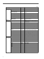
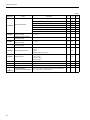
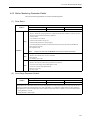
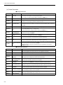
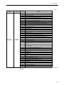
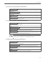
Axis Motion Parameters (Sorted by Register)
Register
IWxx00
xxiv
Variable Name
MonitorMask
Comments
Drive status mask
IBxx000
Monitor.PowerUp SeqDone
Motion controller ready
IBxx001
Monitor.ServoOn
Servo is energized.
IBxx002
Monitor.ServoBusy
System is busy.
IBxx003
Monitor.ServoReady
Servo is ready.
IWxx01
Alarm.OutOfRangeParameter
Parameter number that is over range
ILxx02
Warning.AllMask
Warning mask
IBxx020
Warning.FollowingError
Following error warning
IBxx021
Warning.DynamicParameterOutOfRange
Dynamic parameter out of range warning
IBxx022
Warning.StaticParameterOutOfRange
Static parameter out of range warning
IBxx023
Warning.Mlink
Servo warning
IBxx024
Warning.InvalidCommand
Command Setting Error
IBxx026
Warning.PositiveOvertravel
Positive overtravel warning
IBxx027
Warning.NegativeOvertravel
Negative overtravel warning
IBxx028
Warning.ServoNotEnabled
Servo not energized warning
IBxx029
Warning.Communication
Servo communication warning
ILxx04
Alarm.AllMask
Alarm mask
IBxx040
Alarm.NetworkServo
Servo alarm
IBxx041
Alarm.NegativeOvertravel
Positive overtravel alarm
IBxx042
Alarm.PositiveOvertravel
Negative overtravel alarm
IBxx043
Alarm.PositiveSoftLimit
Positive software limit alarm
IBxx044
Alarm.NegativeSoftLimit
Negative software limit alarm
IBxx045
Alarm.ServoNotEnabled
Servo OFF alarm
IBxx046
Alarm.PositionCompletionTimeOut
Positioning timeout alarm
IBxx047
Alarm.PositionValueOutOfRange
Positioning out of range alarm
IBxx048
Alarm.SpeedOutOfRange
Speed out of range alarm
IBxx049
Alarm.FollowingError
Following error exceeded alarm
IBxx04A
Alarm.FilterTypeChanged
Filter type changed while in motion alarm
IBxx04B
Alarm.FilterTimeChanged
Filter time constant changed while in motion alarm
IBxx04D
Alarm.NotHomed
Zero point not set alarm
IBxx04E
Alarm.HomingWhileMoving
Zero point set while in motion alarm
IBxx04F
Alarm.ServoParameterOutOfRange
Servo parameter alarm
IBxx050
Alarm.ServoCommunicationTimeout
Servo communication synchronization alarm
IBxx051
Alarm.ServoCommunication
Servo communication alarm
IBxx052
Alarm.ServoCommandTimeout
Servo command timeout alarm
IBxx053
Alarm.ABSEncoderOverrange
Absolute encoder number of rotations exceeded alarm
IWxx08
Command.GetValue
Servo command response
IWxx09
Command.Status
Servo command status mask
IBxx090
Command.Busy
Servo command busy
IBxx091
Command.Hold
Servo command holding
IBxx093
Command.Fail
Servo command failed
IBxx098
Command.Complete
Servo command complete
IWxx0A
Command2.GetValue
Servo Command2 response
IWxx0B
Command2.Status
Servo Command2 status mask
IBxx0B0
Command2.Busy
Servo Command2 busy
IBxx0B3
Command2.Fail
Servo Command2 Failed
(cont’d)
Register
Variable Name
Comments
IBxx0B8
Command2.Complete
Servo Command2 complete
IWxx0C
StatusMask
Status mask
IBxx0C0
Position.ProfilerComplete
Profiler complete (DEN)
IBxx0C1
Position.InPosition
In position (POSCOMP)
IBxx0C2
Latch.Complete
Latch complete (LCOMP)
IBxx0C3
Position.InPosition2
Second in position (NEAR)
IBxx0C4
Home.AtHome
At home position (ZERO)
IBxx0C5
Home.Complete
Home complete
IBxx0C6
SimulationActive
Simulation active or machine locked (MLKL)
IBxx0C8
Position.AbsDataRestored
Absolute data has been restored (ABSLDE).
IBxx0C9
Modulus.TurnsInitialized
Number of turns initialized (TPRSE)
ILxx0E
Position.IncTarget
Commanded position (TPOS)
ILxx10
Position.IncTargetModularized
Modularized commanded position per scan (CPOS)
ILxx12
Position.IncTargetModularized2
Commanded position per scan (MPOS)
ILxx16
Position.Actual
Actual (feedback) position (APOS)
ILxx18
Latch.Value
Latch position (LPOS)
ILxx1A
Position.Error
Position error (PERR)
ILxx1C
Position.CommandedPerScan
Commanded position per each scan
ILxx1E
Modulus.Turns
POSMAX Number of turns
ILxx20
Speed.CommandedResponse
Speed commanded response
IWxx2C
StatusMaskN
Servo status mask
IBxx2C0
Alarm.Active
Servo status ALM
IBxx2C1
Warning.Active
Servo status WARNING
IBxx2C2
Command.Ready
Servo status CMDRDY
IBxx2C3
Monitor.ServoOnN
Servo status SVON
IBxx2C4
Monitor.ServoReadyN
Servo status PON
IBxx2C5
SimulationActiveN
Servo status MLOCK
IBxx2C6
Home.AtHomeN
Servo status ZPOINT
IBxx2C7
Position.InPositionN
Servo status PSET
IBxx2C8
Position.ProfilerCompleteN
Servo status DEN
IBxx2C9
Torque.Limited
Servo status T_LIM
IBxx2CA
Latch.CompleteN
Servo status L_CMP
IBxx2CB
Position.InPosition2N
Servo status NEAR
IBxx2CC
Alarm.PositiveSoftLimitN
Servo status P SOT
IWxx2D
Alarm.Code
Servo Alarm Code
IBxx2CD
Alarm.NegativeSoftLimitN
Servo status N SOT
IWxx2E
IO.All
Servo I_O mask
IBxx2E0
IO.PositiveOvertravel
Servo I_O P OT
IBxx2E1
IO.NegativeOvertravel
Servo I_O N OT
IBxx2E2
IO.Home
Servo I_O DEC
IBxx2E3
IO.PhaseA
Servo I_O PA
IBxx2E4
IO.PhaseB
Servo I_O PB
IBxx2E5
IO.PhaseC
Servo I_O PC
IBxx2E6
IO.EXT1
Servo I_O EXT1
IBxx2E7
IO.EXT2
Servo I_O EXT2
IBxx2E8
IO.EXT3
Servo I_O EXT3
IBxx2E9
IO.Brake
Servo I_O BRK
IBxx2EC
IO.IO12
Servo I_O IO12
IBxx2ED
IO.IO13
Servo I_O IO13
xxv
(cont’d)
Register
Variable Name
Comments
IBxx2EE
IO.IO14
Servo I_O IO14
IBxx2EF
IO.IO15
Servo I_O IO15
IWxx2F
Monitor.TypeResponse
Servo monitor information
ILxx30
Monitor.Monitor2Value
Monitor2
ILxx32
Monitor.Monitor3Value
Monitor3
ILxx34
Monitor.Monitor4Value
Monitor4
ILxx38
ServoParameter.GetValue
Requested parameter value
IWxx36
ServoParameter.GetNumber
Requested parameter number (Pn)
IWxx37
ServoParameter2.GetNumber
Second requested parameter number (Pn)
ILxx3A
ServoParameter2.GetValue
Second requested parameter value
IWxx3F
MotorType
0=rotary, 1=linear
ILxx40
Speed.Actual
Actual motor speed
ILxx42
Torque.Actual
Actual motor torque
ILxx56
Command.StaticParameterValue
The value of the fixed parameter read by Command2=5.
ILxx5E
Encoder.Get.AbsolutePositionLS
Contains absolute position used in infinite length
applications.
ILxx60
Encoder.Get.AbsolutePositionMS
Contains absolute position used in infinite length
applications.
ILxx62
Encoder.Get.ModularPositionLS
Contains modularized position used in infinite length
applications.
ILxx64
Encoder.Get.ModularPositionMS
Contains modularized position used in infinite length
applications.
OWxx00
SettingsMask
Various Servo bits packed into a word (mask)
OBxx000
ServoOn
Sets bit to energize servo.
OBxx001
Simulate
In simulation mode, servo will not move.
OBxx004
Latch.Enable
Sets bit to activate latch trigger.
OBxx006
Modulus.InitializeTurns
This will set the number of rotations for a modularized axis.
OBxx007
Position.AbsDataRestore
Loads current position with ABS encoder position at last power off.
OBxx008
Torque.ActivateFwdLimit
Enables external forward torque limit set by servo
parameter.
OBxx009
Torque.ActivateRevLimit
Enables external reverse torque limit set by servo
parameter.
OBxx00B
Gain.IntegralClear
Resets position loop integral value.
OBxx00F
Alarm.Clear
Clears servo alarms.
OWxx01
ModeMask
Various Servo bits packed into a word (mask)
OBxx010
Position.ErrorType
Sets whether position error will trigger an alarm(0) or warning(1).
OBxx013
Gain.SpeedLoopType
Closes speed loop using Proportional and Integral
control(0) or P control(1).
OBxx014
Gain.Select
Enables second set of servo gain parameters.
OBxx020
Monitor.Monitor2Enable
Enables second monitor.
BITS 0 to 3, Set speed units 0=Ref/s 1=10n ref/min 2=% BITS 4 to 7,
xxvi
OWxx03
UnitsWord
OWxx04
SignalSelectionWord
Selects latch input signal and offset input signal.
OBxx051
Position.PhasePositionLoopEnable
Closes position loop with OLxx16.
Set acc/dec units 0=Ref/s2 1=ms BITS 8 to 11, Set acc/dec filter 0=none
1=exponential 2=moving average
OBxx058
Home.DecelerationLS
Selects homing deceleration LS signal.
OBxx059
Home.ReverseLimit
Selects homing reverse limit signal.
OBxx05A
Home.ForwardLimit
Selects homing forward limit signal.
OBxx05B
InputSelect
Selects homing input signal.
OWxx08
Command.SetValue
SERVOPACK command
(cont’d)
Register
Variable Name
Comments
OWxx0E
Torque.SpeedLimit
Maximum speed allowed during torque control
OWxx09
CommandMask
Servo Command options
OBxx090
Command.Pause
Pause command
OBxx091
Command.Abort
Abort command
OBxx092
Command.JogRelativeMoveDirection
Selects Jog or Step direction.
OBxx093
Home.Direction
Selects home direction.
OBxx094
Latch.WindowEnable
Enables the latch zone.
OWxx0A
Command2.SetValue
Additional servopack commands
OLxx0C
Torque.Commanded
The commanded motor torque in % of rated 100=1%
OLxx10
Speed.Commanded
Commanded speed in units based on UnitType
OLxx14
Speed.TorqueLimit
Maximum torque allowed during speed control
OWxx18
Speed.Override
The percentage of commanded speed actually achieved 100=1%
OLxx1C
Position.Commanded
Commanded position, incremental or absolute based on MoveType
OLxx1E
Position.InPositionWindow
Position window that determines when InPosition will be set (when
Actual=Commanded ± Window)
OLxx20
Position.InPosition2Window
Position window that determines when InPosition2
will be set (when Actual=Commanded ± Window2)
OLxx22
Position.ErrorLimit
The value (in user units) that triggers a position error alarm or warning
when exceeded
OLxx28
Position.PhaseCompensation
Position units added to the commanded position in phase control mode.
OWxx26
Position.InPositionTimeOut
The value (in milliseconds) that triggers a position
complete timeout alarm after the profilier is complete
OLxx2A
Latch.WindowLowerLimit
The lower limit of the latch window
OLxx2C
Latch.WindowUpperLimit
The upper limit of the latch window
OWxx2E
Gain.PositionLoop
Increase value for more rigid control.
OWxx2F
Gain.SpeedLoop
Increases value for more rigid dampening.
OWxx30
Gain.PositionFeedForward
Feed Forward adds to the position to increase response
OWxx31
Gain.PhaseFeedForward
Add to the speed in 0.01%
OWxx32
Gain.PositionIntegration
Time in ms used to integrate the position error
OWxx34
Gain.SpeedIntegration
Time in ms used to integrate the speed error
OLxx36
Acceleration
Acceleration Value, units selected by UnitsWord
(OWxx03)
OLxx38
Deceleration
Deceleration value, units selected by UnitsWord
(OWxx03)
OWxx3A
S_CurveTime
Softens acceleration or deceleration.
OWxx3C
Home.Method
The type of homing to perform
OWxx3D
Home.CompleteWindow
The window used to set the home complete bit
OLxx3E
Home.ApproachSpeed
Speed used in the first or second stage of homing
depending on type
OLxx40
Home.CreepSpeed
Speed used to locate the "c" channel or marker pulse
OLxx42
Home.Offset
Offset distance used at the end of homing
OLxx44
Position.Relative
Distance used in the step command
OLxx46
Position.Offset
The offset distance that the motor will travel during the external
positioning command if the external positioning signal is activated
during the move
OLxx48
Home.Define
Redefine the coordinate system. In position mode, the servo will move
when this variable is changed.
OLxx4A
Position.WorkCoordinateOffset
Offset for interpolation commands
Modulus.SetTurns
Value used to set the number of turns, or times the
position has rolled over the maximum
OLxx4C
xxvii
(cont’d)
Register
xxviii
Variable Name
Comments
Selects which value will be returned from the servopack. Bits 4 to 7 set
monitor2and bits C to F set monitor4
OWxx4E
Monitor.Type
OWxx4F
Alarm.MonitorNumber
This value determines which of the last 10 alarm codes are returned.
OWxx50
ServoParameter.SetNumber
The number of the amplifier parameter to be read or set
OWxx51
ServoParameter.SetSize
The size of the amplifier parameter data
OLxx52
ServoParameter.SetValue
The value to be set for the amplifier parameter
OWxx54
ServoParameter2.SetNumber
The number of the second amplifier parameter to be read or set
OWxx55
ServoParameter2.SetSize
The size of the second amplifier parameter data
OLxx56
ServoParameter2.SetValue
The value to be set for the second amplifier parameter
OWxx5C
Command.StaticParameterNumber
The number of the static parameter to be read when Command2=5
OLxx5E
Encoder.Set.AbsolutePositionLS
Used to set the absolute position used in infinite
length applications.
OLxx60
Encoder.Set.AbsolutePositionMS
Used to set the absolute position used in infinite
length applications.
OLxx62
Encoder.Set.ModularPositionLS
Used to set the modularized position used in infinite
length applications.
OLxx64
Encoder.Set.ModularPositionMS
Used to set the modularized position used in infinite
length applications.
OBxx95
Position.MoveType
Selects positioning. 0=incremental 1=absolete
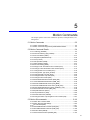
CONTENTS
Using this Manual - - - - - - - - - - - - - - - - - - - - - - - - - - - - - - - - - - - - - - - - - - - - - - - - - - - - - - - iii
Safety Information - - - - - - - - - - - - - - - - - - - - - - - - - - - - - - - - - - - - - - - - - - - - - - - - - - - - - - - vii
Safety Precautions - - - - - - - - - - - - - - - - - - - - - - - - - - - - - - - - - - - - - - - - - - - - - - - - - - - - - viii
Variable Tables - - - - - - - - - - - - - - - - - - - - - - - - - - - - - - - - - - - - - - - - - - - - - - - - - - - - - - - - xiii
Motion Module Overview
1.1 List of Motion Modules - - - - - - - - - - - - - - - - - - - - - - - - - - - - - - - - - - - - - - - - - 1-2
1.2 SVB-01 Module Overview and Features - - - - - - - - - - - - - - - - - - - - - - - - - - - - - 1-4
1.2.1 Overview - - - - - - - - - - - - - - - - - - - - - - - - - - - - - - - - - - - - - - - - - - - - - - - - - - - - - - - - - - - - 1-4
1.2.2 Features - - - - - - - - - - - - - - - - - - - - - - - - - - - - - - - - - - - - - - - - - - - - - - - - - - - - - - - - - - - - - 1-4
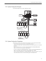
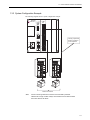
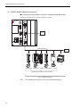
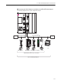
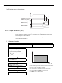
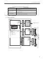
1.2.3 System Configuration Example - - - - - - - - - - - - - - - - - - - - - - - - - - - - - - - - - - - - - - - - - - - - - 1-5
1.2.4 System Configuration Precautions - - - - - - - - - - - - - - - - - - - - - - - - - - - - - - - - - - - - - - - - - - 1-5
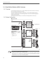
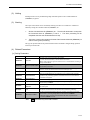
1.2.5 Devices Connectable to MECHATROLINK- - - - - - - - - - - - - - - - - - - - - - - - - - - - - - - - - - - - - 1-6
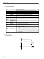
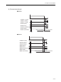
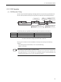
1.2.6 Synchronization between Modules - - - - - - - - - - - - - - - - - - - - - - - - - - - - - - - - - - - - - - - - - - 1-7
1.3 SVA-01 Module Overview and Features - - - - - - - - - - - - - - - - - - - - - - - - - - - - - 1-9
1.3.1 Overview - - - - - - - - - - - - - - - - - - - - - - - - - - - - - - - - - - - - - - - - - - - - - - - - - - - - - - - - - - - - 1-9
1.3.2 Features - - - - - - - - - - - - - - - - - - - - - - - - - - - - - - - - - - - - - - - - - - - - - - - - - - - - - - - - - - - - 1-10
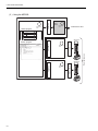
1.3.3 System Configuration Example - - - - - - - - - - - - - - - - - - - - - - - - - - - - - - - - - - - - - - - - - - - - 1-11
1.4 Virtual Motion Module (SVR) Overview - - - - - - - - - - - - - - - - - - - - - - - - - - - - - 1-12
1.4.1 Overview - - - - - - - - - - - - - - - - - - - - - - - - - - - - - - - - - - - - - - - - - - - - - - - - - - - - - - - - - - - 1-12
1.4.2 System Configuration - - - - - - - - - - - - - - - - - - - - - - - - - - - - - - - - - - - - - - - - - - - - - - - - - - 1-12
Module Specifications and Connections
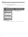
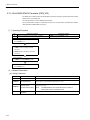
2.1 SVB-01 Module Specifications and Connections - - - - - - - - - - - - - - - - - - - - - - - 2-2
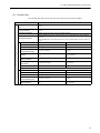
2.1.1 General Specifications - - - - - - - - - - - - - - - - - - - - - - - - - - - - - - - - - - - - - - - - - - - - - - - - - - - 2-2
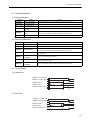
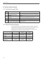
2.1.2 LED Indicators and Switch Settings- - - - - - - - - - - - - - - - - - - - - - - - - - - - - - - - - - - - - - - - - - 2-6
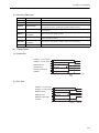
2.1.3 Module Connections - - - - - - - - - - - - - - - - - - - - - - - - - - - - - - - - - - - - - - - - - - - - - - - - - - - - 2-8
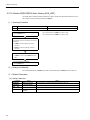
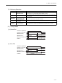
2.2 SVA-01 Module Specifications and Connections - - - - - - - - - - - - - - - - - - - - - - 2-14
2.2.1 General Specifications - - - - - - - - - - - - - - - - - - - - - - - - - - - - - - - - - - - - - - - - - - - - - - - - - - 2-14
2.2.2 LED Indicators and Switch Settings- - - - - - - - - - - - - - - - - - - - - - - - - - - - - - - - - - - - - - - - - 2-18
2.2.3 Module Connections - - - - - - - - - - - - - - - - - - - - - - - - - - - - - - - - - - - - - - - - - - - - - - - - - - - 2-19
Motion Module Setup
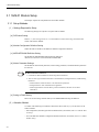
3.1 SVB-01 Module Setup- - - - - - - - - - - - - - - - - - - - - - - - - - - - - - - - - - - - - - - - - - 3-2
3.1.1 Setup Methods - - - - - - - - - - - - - - - - - - - - - - - - - - - - - - - - - - - - - - - - - - - - - - - - - - - - - - - - 3-2
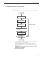
3.1.2 Self-configuration - - - - - - - - - - - - - - - - - - - - - - - - - - - - - - - - - - - - - - - - - - - - - - - - - - - - - - 3-3
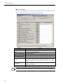
3.1.3 Module Configuration Definitions - - - - - - - - - - - - - - - - - - - - - - - - - - - - - - - - - - - - - - - - - - 3-12
3.2 SVA-01 Module Setup- - - - - - - - - - - - - - - - - - - - - - - - - - - - - - - - - - - - - - - - - 3-26
xxix
3.2.1 Setup Method- - - - - - - - - - - - - - - - - - - - - - - - - - - - - - - - - - - - - - - - - - - - - - - - - - - - - - - - - 3-26
3.2.2 Self-configuration - - - - - - - - - - - - - - - - - - - - - - - - - - - - - - - - - - - - - - - - - - - - - - - - - - - - - - 3-26
3.2.3 Module Configuration Definitions - - - - - - - - - - - - - - - - - - - - - - - - - - - - - - - - - - - - - - - - - - - 3-29
3.2.4 Servo Parameter Settings - - - - - - - - - - - - - - - - - - - - - - - - - - - - - - - - - - - - - - - - - - - - - - - - 3-36
3.3 SVR Module Setup - - - - - - - - - - - - - - - - - - - - - - - - - - - - - - - - - - - - - - - - - - - 3-44
3.3.1 Module Configuration Definition - - - - - - - - - - - - - - - - - - - - - - - - - - - - - - - - - - - - - - - - - - - - 3-44
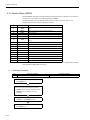
Motion Parameters
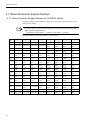
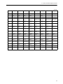
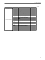
4.1 Motion Parameters Register Numbers - - - - - - - - - - - - - - - - - - - - - - - - - - - - - - 4-2
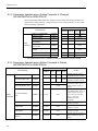
4.1.1 Motion Parameter Register Numbers for the SVB-01 Module - - - - - - - - - - - - - - - - - - - - - - - -4-2
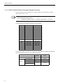
4.1.2 SVA-01 Module Motion Parameter Register Numbers - - - - - - - - - - - - - - - - - - - - - - - - - - - - -4-4
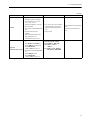
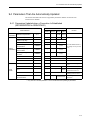
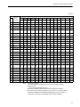
4.2 Motion Parameter Lists - - - - - - - - - - - - - - - - - - - - - - - - - - - - - - - - - - - - - - - - - 4-5
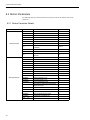
4.2.1 Fixed Parameter List- - - - - - - - - - - - - - - - - - - - - - - - - - - - - - - - - - - - - - - - - - - - - - - - - - - - -4-5
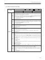
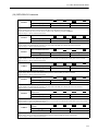
4.2.2 Setting Parameter List - - - - - - - - - - - - - - - - - - - - - - - - - - - - - - - 4-7
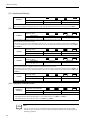
4.2.3 Monitoring Parameter List - - - - - - - - - - - - - - - - - - - - - - - - - - - - - - - - - - - - - - - - - - - - - - - - 4-13
4.3 SVB-01 Module Parameter Details - - - - - - - - - - - - - - - - - - - - - - - - - - - - - - - - 4-17
4.3.1 Motion Fixed Parameter Details - - - - - - - - - - - - - - - - - - - - - - - - - - - - - - - - - - - - - - - - - - - - 4-17
4.3.2 Motion Setting Parameter Details - - - - - - - - - - - - - - - - - - - - - - - - - - - - - - - - - - - - - - - - - - - 4-23
4.3.3 Motion Monitoring Parameter Details - - - - - - - - - - - - - - - - - - - - - - - - - - - - - - - - - - - - - - - - 4-45
4.4 SVA-01 Module Parameter Details - - - - - - - - - - - - - - - - - - - - - - - - - - - - - - - - 4-60
4.4.1 Motion Fixed Parameter Details - - - - - - - - - - - - - - - - - - - - - - - - - - - - - - - - - - - - - - - - - - - - 4-60
4.4.2 Motion Setting Parameter Details - - - - - - - - - - - - - - - - - - - - - - - - - - - - - - - - - - - - - - - - - - - 4-68
4.4.3 Motion Monitoring Parameter Details - - - - - - - - - - - - - - - - - - - - - - - - - - - - - - - - - - - - - - - - 4-87
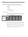
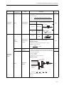
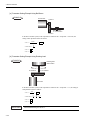
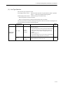
4.5 Example of Setting Motion Parameters for the Machine - - - - - - - - - - - - - - - - 4-100
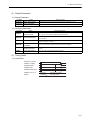
Motion Commands
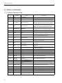
5.1 Motion Commands - - - - - - - - - - - - - - - - - - - - - - - - - - - - - - - - - - - - - - - - - - - - 5-2
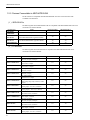
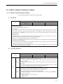
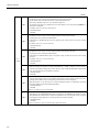
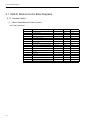
5.1.1 Motion Command Table - - - - - - - - - - - - - - - - - - - - - - - - - - - - - - - - - - - - - - - - - - - - - - - - - -5-2
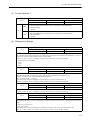
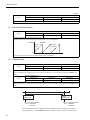
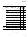
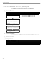
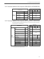
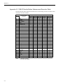
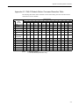
5.1.2 Motion Commands Supported by SERVOPACK Models- - - - - - - - - - - - - - - - - - - - - - - - - - - -5-3
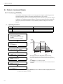
5.2 Motion Command Details - - - - - - - - - - - - - - - - - - - - - - - - - - - - - - - - - - - - - - - 5-4
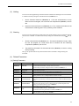
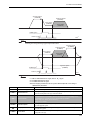
5.2.1 Positioning (POSING) - - - - - - - - - - - - - - - - - - - - - - - - - - - - - - - - - - - - - - - - - - - - - - - - - - - -5-4
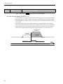
5.2.2 External Positioning (EX_POSING) - - - - - - - - - - - - - - - - - - - - - - - - - - - - - - - - - - - - - - - - - -5-9
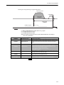
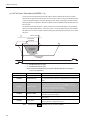
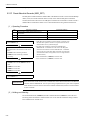
5.2.3 Zero Point Return (ZRET) - - - - - - - - - - - - - - - - - - - - - - - - - - - - - - - - - - - - - - - - - - - - - - - - 5-15
5.2.4 Interpolation (INTERPOLATE) - - - - - - - - - - - - - - - - - - - - - - - - - - - - - - - - - - - - - - - - - - - - - 5-56
5.2.5 Latch (LATCH) - - - - - - - - - - - - - - - - - - - - - - - - - - - - - - - - - - - - - - - - - - - - - - - - - - - - - - - - 5-59
5.2.6 JOG Operation (FEED) - - - - - - - - - - - - - - - - - - - - - - - - - - - - - - - - - - - - - - - - - - - - - - - - - - 5-64
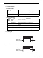
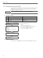
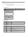
5.2.7 STEP Operation (STEP) - - - - - - - - - - - - - - - - - - - - - - - - - - - - - - - - - - - - - - - - - - - - - - - - - 5-67
5.2.8 Zero Point Setting (ZSET) - - - - - - - - - - - - - - - - - - - - - - - - - - - - - - - - - - - - - - - - - - - - - - - - 5-72
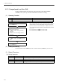
5.2.9 Change Linear Acceleration Time Constant (ACC)- - - - - - - - - - - - - - - - - - - - - - - - - - - - - - - 5-74
5.2.10 Change Linear Deceleration Time Constant (DCC) - - - - - - - - - - - - - - - - - - - - - - - - - - - - - 5-76
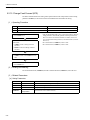
5.2.11 Change Filter Time Constant (SCC) - - - - - - - - - - - - - - - - - - - - - - - - - - - - - - - - - - - - - - - - 5-78
xxx
5.2.12 Change Filter Type (CHG_FILTER) - - - - - - - - - - - - - - - - - - - - - - - - - - - - - - - - - - - - - - - - 5-80
5.2.13 Change Speed Loop Gain (KVS)- - - - - - - - - - - - - - - - - - - - - - - - - - - - - - - - - - - - - - - - - - 5-82
5.2.14 Change Position Loop Gain (KPS) - - - - - - - - - - - - - - - - - - - - - - - - - - - - - - - - - - - - - - - - 5-84
5.2.15 Change Feed Forward (KFS) - - - - - - - - - - - - - - - - - - - - - - - - - - - - - - - - - - - - - - - - - - - - 5-86
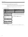
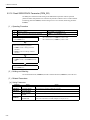
5.2.16 Read SERVOPACK Parameter (PRM_RD) - - - - - - - - - - - - - - - - - - - - - - - - - - - - - - - - - - 5-88
5.2.17 Write SERVOPACK Parameter (PRM_WR) - - - - - - - - - - - - - - - - - - - - - - - - - - - - - - - - - - 5-90
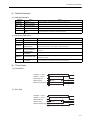
5.2.18 Monitor SERVOPACK Alarms (ALM_MON) - - - - - - - - - - - - - - - - - - - - - - - - - - - - - - - - - - 5-92
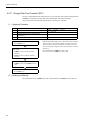
5.2.19 Monitor SERVOPACK Alarm History (ALM_HIST) - - - - - - - - - - - - - - - - - - - - - - - - - - - - - 5-94
5.2.20 Clear SERVOPACK Alarm History (ALMHIST_CLR) - - - - - - - - - - - - - - - - - - - - - - - - - - - - 5-96
5.2.21 Reset Absolute Encoder (ABS_RST)- - - - - - - - - - - - - - - - - - - - - - - - - - - - - - - - - - - - - - - 5-98
5.2.22 Speed Reference (VELO) - - - - - - - - - - - - - - - - - - - - - - - - - - - - - - - - - - - - - - - - - - - - - - 5-100
5.2.23 Torque Reference (TRQ) - - - - - - - - - - - - - - - - - - - - - - - - - - - - - - - - - - - - - - - - - - - - - - 5-104
5.2.24 Phase References (PHASE) - - - - - - - - - - - - - - - - - - - - - - - - - - - - - - - - - - - - - - - - - - - - -5-110
5.2.25 Change Position Loop Integration Time Constant (KIS) - - - - - - - - - - - - - - - - - - - - - - - - - -5-114
5.3 Motion Subcommands - - - - - - - - - - - - - - - - - - - - - - - - - - - - - - - - - - - - - - - 5-116
5.3.1 Motion Sub-command Table - - - - - - - - - - - - - - - - - - - - - - - - - - - - - - - - - - - - - - - - - - - - - -5-116
5.3.2 Motion Subcommand Settings - - - - - - - - - - - - - - - - - - - - - - - - - - - - - - - - - - - - - - - - - - - -5-116
5.3.3 No Command (NOP) - - - - - - - - - - - - - - - - - - - - - - - - - - - - - - - - - - - - - - - - - - - - - - - - - - -5-117
5.3.4 Read SERVOPACK Parameter (PRM_RD) - - - - - - - - - - - - - - - - - - - - - - - - - - - - - - - - - - -5-118
5.3.5 Write SERVOPACK Parameter (PRM_WR) - - - - - - - - - - - - - - - - - - - - - - - - - - - - - - - - - - 5-120
5.3.6 Monitor Status (SMON) - - - - - - - - - - - - - - - - - - - - - - - - - - - - - - - - - - - - - - - - - - - - - - - - 5-122
5.3.7 Read Fixed Parameters (FIXPRM_RD) - - - - - - - - - - - - - - - - - - - - - - - - - - - - - - - - - - - - - 5-124
Control Block Diagrams
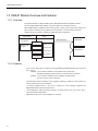
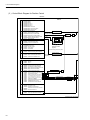
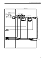
6.1 SVB-01 Module Control Block Diagrams- - - - - - - - - - - - - - - - - - - - - - - - - - - - - 6-2
6.1.1 Position Control- - - - - - - - - - - - - - - - - - - - - - - - - - - - - - - - - - - - - - - - - - - - - - - - - - - - - - - - 6-2
6.1.2 Phase Control - - - - - - - - - - - - - - - - - - - - - - - - - - - - - - - - - - - - - - - - - - - - - - - - - - - - - - - - - 6-8
6.1.3 Torque Control - - - - - - - - - - - - - - - - - - - - - - - - - - - - - - - - - - - - - - - - - - - - - - - - - - - - - - - 6-14
6.1.4 Speed Control - - - - - - - - - - - - - - - - - - - - - - - - - - - - - - - - - - - - - - - - - - - - - - - - - - - - - - - - 6-20
6.2 SVA-01 Module Control Block Diagram- - - - - - - - - - - - - - - - - - - - - - - - - - - - - 6-26
Absolute Position Detection
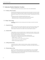
7.1 Absolute Position Detection Function - - - - - - - - - - - - - - - - - - - - - - - - - - - - - - - 7-2
7.1.1 Outline of the Function- - - - - - - - - - - - - - - - - - - - - - - - - - - - - - - - - - - - - - - - - - - - - - - - - - - 7-2
7.1.2 Basic Terminology - - - - - - - - - - - - - - - - - - - - - - - - - - - - - - - - - - - - - - - - - - - - - - - - - - - - - - 7-2
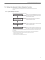
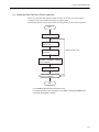
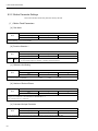
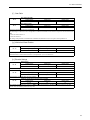
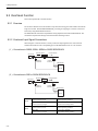
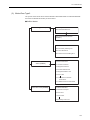
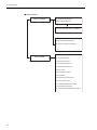
7.2 Startup the Absolute Position Detection Function- - - - - - - - - - - - - - - - - - - - - - - 7-3
7.2.1 System Startup Procedure - - - - - - - - - - - - - - - - - - - - - - - - - - - - - - - - - - - - - - - - - - - - - - - - 7-3
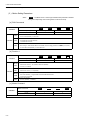
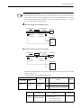
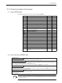
7.2.2 Setting Related Parameters - - - - - - - - - - - - - - - - - - - - - - - - - - - - - - - - - - - - - - - - - - - - - - - 7-4
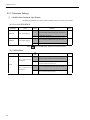
7.2.3 Initializing the Absolute Encoder - - - - - - - - - - - - - - - - - - - - - - - - - - - - - - - - - - - - - - - - - - - - 7-8
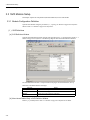
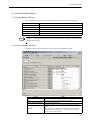
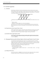
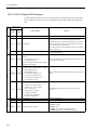
7.3 Using an Absolute Encoder - - - - - - - - - - - - - - - - - - - - - - - - - - - - - - - - - - - - - 7-13
7.3.1 Finite Length Axis - - - - - - - - - - - - - - - - - - - - - - - - - - - - - - - - - - - - - - - - - - - - - - - - - - - - - 7-13
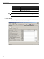
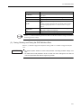
7.3.2 Infinite Length Axis - - - - - - - - - - - - - - - - - - - - - - - - - - - - - - - - - - - - - - - - - - - - - - - - - - - - 7-18
xxxi
SVR Virtual Motion Module
8.1 SVR Virtual Motion Module - - - - - - - - - - - - - - - - - - - - - - - - - - - - - - - - - - - - - - 8-2
8.1.1 Overview - - - - - - - - - - - - - - - - - - - - - - - - - - - - - - - - - - - - - - - - - - - - - - - - - - - - - - - - - - - - -8-2
8.1.2 System Configuration - - - - - - - - - - - - - - - - - - - - - - - - - - - - - - - - - - - - - - - - - - - - - - - - - - - -8-3
8.1.3 SVR Operation - - - - - - - - - - - - - - - - - - - - - - - - - - - - - - - - - - - - - - - - - - - - - - - - - - - - - - - - -8-5
8.2 Motion Parameters - - - - - - - - - - - - - - - - - - - - - - - - - - - - - - - - - - - - - - - - - - - - 8-6
8.2.1 Motion Parameter Details - - - - - - - - - - - - - - - - - - - - - - - - - - - - - - - - - - - - - - - - - - - - - - - - -8-6
8.2.2 Motion Parameter Settings - - - - - - - - - - - - - - - - - - - - - - - - - - - - - - - - - - - - - - - - - - - - - - - -8-8
8.3 Motion Commands - - - - - - - - - - - - - - - - - - - - - - - - - - - - - - - - - - - - - - - - - - - 8-17
8.3.1 Motion Commands List - - - - - - - - - - - - - - - - - - - - - - - - - - - - - - - - - - - - - - - - - - - - - - - - - - 8-17
8.3.2 Motion Command Details - - - - - - - - - - - - - - - - - - - - - - - - - - - - - - - - - - - - - - - - - - - - - - - - 8-18
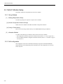
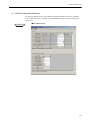
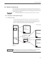
8.4 Sample Programming - - - - - - - - - - - - - - - - - - - - - - - - - - - - - - - - - - - - - - - - - 8-39
8.4.1 Description of the Sample Program - - - - - - - - - - - - - - - - - - - - - - - - - - - - - - - - - - - - - - - - - 8-39
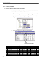
8.4.2 Checking Operation - - - - - - - - - - - - - - - - - - - - - - - - - - - - - - - - - - - - - - - - - - - - - - - - - - - - 8-40
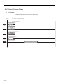
8.4.3 Sample Program Details - - - - - - - - - - - - - - - - - - - - - - - - - - - - - - - - - - - - - - - - - - - - - - - - - 8-42
Utility Functions
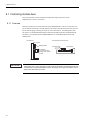
9.1 Controlling Vertical Axes - - - - - - - - - - - - - - - - - - - - - - - - - - - - - - - - - - - - - - - - 9-2
9.1.1 Overview - - - - - - - - - - - - - - - - - - - - - - - - - - - - - - - - - - - - - - - - - - - - - - - - - - - - - - - - - - - - -9-2
9.1.2 Connections to Σ-II and Σ-III SERVOPACK - - - - - - - - - - - - - - - - - - - - - - - - - - - - - - - - - - - -9-3
9.1.3 Connections to Σ Series SGDB SERVOPACK - - - - - - - - - - - - - - - - - - - - - - - - - - - - - - - - - - -9-6
9.1.4 Connections to Σ Series SGD or SGDA SERVOPACK - - - - - - - - - - - - - - - - - - - - - - - - - - - - -9-9
9.2 Overtravel Function - - - - - - - - - - - - - - - - - - - - - - - - - - - - - - - - - - - - - - - - - - 9-12
9.2.1 Overview - - - - - - - - - - - - - - - - - - - - - - - - - - - - - - - - - - - - - - - - - - - - - - - - - - - - - - - - - - - - 9-12
9.2.2 Overtravel Input Signal Connections- - - - - - - - - - - - - - - - - - - - - - - - - - - - - - - - - - - - - - - - - 9-12
9.2.3 Parameter Settings - - - - - - - - - - - - - - - - - - - - - - - - - - - - - - - - - - - - - - - - - - - - - - - - - - - - - 9-14
9.3 Software Limit Function- - - - - - - - - - - - - - - - - - - - - - - - - - - - - - - - - - - - - - - - 9-17
9.3.1 Overview - - - - - - - - - - - - - - - - - - - - - - - - - - - - - - - - - - - - - - - - - - - - - - - - - - - - - - - - - - - - 9-17
9.3.2 Fixed Parameter Settings - - - - - - - - - - - - - - - - - - - - - - - - - - - - - - - - - - - - - - - - - - - - - - - - 9-17
9.3.3 Processing after an Alarm Occurs - - - - - - - - - - - - - - - - - - - - - - - - - - - - - - - - - - - - - - - - - - 9-18
9.4 Parameters That Are Automatically Updated - - - - - - - - - - - - - - - - - - - - - - - - - 9-19
9.4.1 Parameters Updated when a Connection Is Established
(MP2200/MP2300 to SERVOPACK)- - - - - - - - - - - - - - - - - - - - - - - - - - - - - - - - - - - - - - - - - 9-19
9.4.2 Parameters Updated when a Setting Parameter Is Changed
(MP2200/MP2300 to SERVOPACK)- - - - - - - - - - - - - - - - - - - - - - - - - - - - - - - - - - - - - - - - - 9-20
9.4.3 Parameters Updated when a Motion Command Is Started
(MP2200/MP2300 to SERVOPACK)- - - - - - - - - - - - - - - - - - - - - - - - - - - - - - - - - - - - - - - - - 9-20
9.4.4 Parameters Updated at Self-configuration (SERVOPACK to MP2200/MP2300) - - - - - - - - - - 9-21
9.4.5 Parameters Updated at Self-configuration (MP2200/MP2300 to SERVOPACK) - - - - - - - - - - 9-21
xxxii
Troubleshooting
10.1 Motion Errors - - - - - - - - - - - - - - - - - - - - - - - - - - - - - - - - - - - - - - - - - - - - - - 10-2
10.1.1 Description of Motion Errors - - - - - - - - - - - - - - - - - - - - - - - - - - - - - - - - - - - - - - - - - - - - - 10-2
10.1.2 Motion Error Details and Corrections - - - - - - - - - - - - - - - - - - - - - - - - - - - - - - - - - - - - - - - 10-5
10.1.3 Motion Program Alarms - - - - - - - - - - - - - - - - - - - - - - - - - - - - - - - - - - - - - - - - - - - - - - - 10-20
10.1.4 Causes of the “Command Error End” Status (SVB-01 Only)- - - - - - - - - - - - - - - - - - - - - - 10-22
10.2 Error Detection - - - - - - - - - - - - - - - - - - - - - - - - - - - - - - - - - - - - - - - - - - - - 10-26
10.2.1 SVB-01 Module LED Indicators- - - - - - - - - - - - - - - - - - - - - - - - - - - - - - - - - - - - - - - - - - 10-26
10.2.2 SVA-01 Module LED Indicators - - - - - - - - - - - - - - - - - - - - - - - - - - - - - - - - - - - - - - - - - - 10-28
Appendix
Appendix A Switching Motion Commands - - - - - - - - - - - - - - - - - - - - - - - - - - - - - - A-2
Appendix A.1 SVB-01 Module Motion Command Execution Tables - - - - - - - - - - - - - - - - - - - - - - - A-2
Appendix A.2 SVB-01 Module Motion Subcommand Execution Table- - - - - - - - - - - - - - - - - - - - - - A-4
Appendix A.3 SVA-01 Module Motion Command Execution Table - - - - - - - - - - - - - - - - - - - - - - - - A-5
xxxiii
xxxiv
1
Motion Module Overview
This chapter provides an overview and the features of the Motion Module.
1.1 List of Motion Modules ............................................................ 1-2
1.2 SVB-01 Module Overview and Features ................................. 1-4
1.2.1 Overview ................................................................................................ 1-4
1.2.2 Features ................................................................................................ 1-4
1.2.3 System Configuration Example ............................................................. 1-5
1.2.4 System Configuration Precautions ........................................................ 1-5
1.2.5 Devices Connectable to MECHATROLINK ........................................... 1-6
1.2.6 Synchronization between Modules ........................................................ 1-7
1.3 SVA-01 Module Overview and Features ................................. 1-9
1.3.1 Overview ................................................................................................ 1-9
1.3.2 Features .............................................................................................. 1-10
1.3.3 System Configuration Example ........................................................... 1-11
1.4 Virtual Motion Module (SVR) Overview ................................. 1-12
1.4.1 Overview .............................................................................................. 1-12
1.4.2 System Configuration .......................................................................... 1-12
1-1
1 Motion Module Overview
1.1 List of Motion Modules
The Motion Modules that can be used with the MP2200/MP2300 are listed below.
Module Description
SVB-01 Module
SVA-01 Module
SVR Module
Name
SVB-01
SVA-01
SVR
Model Number
JAPMC-MC2310
JAPMC-MC2300
−
LED indicators
Switch
LED indicators
SVB-01
RUN
Switch (station
address setting)
SVA-01
ERR
RUN
ERR
TX
CH1
M/S
SIZE
SPD
OFF
ON
10
Servo connectors
1
Module Appearance
MECHATROLINK
Connector
Virtual Motion Module
Refer to 1.4 Virtual Motion
Module (SVR) Overview.
M-I/II
CH2
MECHATROLINK
Connector
CN1
CN2
24-V input connector
+24V
ON
DC IN
Interface
MECHATROLINK-I/II
communication
Analog outputs and feedback pulse
inputs
−
Maximum Number of
Controlled Axes/Module
Up to 16 axes
Up to 2 axes
Up to 16 axes
MP2300: 2 Modules
MP2300: 2 Modules
MP2200: 16 Modules
MP2200: 16 Modules
PTP Control
Linear, rotating, and infinite-length
Linear, rotating, and infinite-length
Linear, rotating, and infinitelength
Interpolation
Up to 16 linear axes, 2 circular axes,
and 3 helical axes
Up to 16 linear axes (with the
MP2200), 2 circular axes, and 3
helical axes
Up to 16 linear axes, 2 circular
axes, and 3 helical axes
Speed Reference
Output
Up to 256 axes
(MECHATROLINK-II, for
MP2200)
Up to 32 axes (with the MP2200)
Up to 16 axes
(MECHATROLINK-II)
Torque Reference
Output
Up to 256 axes
(MECHATROLINK-III, for
MP2200)
Up to 32 axes (with the MP2200)
Up to 16 axes
(MECHATROLINK-II)
Position Control
Positioning, External Positioning,
Zero Point Return, Interpolation,
Interpolation with Position
Detection, JOG operation, and
STEP operation
Same as at left.
Same as at left.
Phase Control
Up to 256 axes
Up to 32 axes (with the MP2200)
Up to 16 axes
Automatically sets data for Module
and Slave devices.
Automatic allocation by Module is
supported.
−
Control Specifications
Maximum Number of
Modules/Machine
Controller
Self-configuration
1-2
1
1.1 List of Motion Modules
(cont’d)
Module Description
SVB-01 Module
SVA-01 Module
SVR Module
Features
• High-speed Motion Network
Baud rate: 4 Mbps or 10 Mbps
Communication cycle: 0.5 ms,
1 ms, 1.5 ms, or 2 ms
Transmission distance: 50 m max.
• Slave Functions
Supported for MECHATROLINKI/II
• Synchronization between
Modules
Synchronization possible when
high-speed scan cycle =
communication cycle times n
• The control cycle is fixed at 500 µs
to enable high-precision control
regardless of the high-speed scan
cycle.
• Analog control
• Synchronization for high-speed
scan
• Position data refreshed every
scan
Applicable
SERVOPACKs/Inverters
• Supported for MECHATROLINKI
SGD-N SGDB-AN
SGDH-E+NS100/NS115
SGDS-1
CIMR-V7 (VS mini V7)
• Supported for MECHATROLINKII
SGDH-E+NS115
SGDS-1
CIMR-V7 (VS mini V7)
SGDA-S,
SGDB-AD-, -DD
SGDM-DA, -AD
SGDH-DE, -AE,
-E
SGDS--01/02, -05,
-A, -F
−
1-3
1 Motion Module Overview
1.2.1 Overview
1.2 SVB-01 Module Overview and Features
1.2.1 Overview
The SVB-01 Module is a Motion Module with a MECHATROLINK-II-compatible interface.
The use of MECHATROLINK enables control of multiple axes with reduced wiring.
MECHATROLINK-II compatibility also enables position control, speed control, torque control, and
phase control, and makes precise synchronous control possible. The control mode can also be
changed during axis operation, facilitating complicated machine operations.
MP2300 CPU
User application
Ladder/motion
program
SVB-01
MECHATROLINK
SERVOPACK
Position reference
Position control
Speed reference
Torque reference
Speed control
Torque control
SERVOPACK
Phase control
Phase reference
1.2.2 Features
• Up to 21 slave stations can be connected to a single Module (the SERVOPACKs can be connected
up to 16 axes).
MP2300: Up to 2 SVB-01 Modules can be installed in the Option Slots.
Including the MP2300’s built-in SVB, up to 48 axes can be controlled.
MP2200: Up to 16 SVB-01 Modules can be installed in the Option Slots.
A total of 256 axes can be controlled.
• Synchronization between Modules is also supported, making it suitable for both synchronous
control and interpolation across Modules.
• An SVB-01 Module used as a slave can be connected to a host controller equipped with
MECHATROLINK communication functions.
•
Self-configuration enables automatic allocation of setting data for the slave device that is
connected to MECHATROLINK.
• SERVOPACK parameters can be managed over networks.
1-4
1.2 SVB-01 Module Overview and Features
1.2.3 System Configuration Example
The following diagram shows a system configuration example.
MP2300
SVB-01 218IF LIO-01
24-VDC
power
supply
External I/O
Control panel
External I/O
RS-232C
MECHATROLINK-II
SGDS
NS115
SGDH
IO2310
PL2900
PL2910
MPE720
M
MECHATROLINKcompatible I/O Modules
Ethernet
M
Servos
SGDS
NS115
SGDH
IO2310
PL2900
PL2910
MECHATROLINK-II
M
MECHATROLINKcompatible I/O Modules
M
Servos
1.2.4 System Configuration Precautions
The following precautions must be followed when designing a system using the SVB-01 Module.
• Use the connecting cables and connectors recommended by Yaskawa.
Yaskawa has a range of cables. Always check the device to be used and select the correct cable for
the device.
• Different SERVOPACKs are connected to MECHATROLINK-I and MECHATROLINK-II.
Refer to the list and select the appropriate SERVOPACKs.
• If devices compatible with MECHATROLINK-I (4 Mbps) and with MECHATROLINK-II (10
Mbps) are used together, make the settings for MECHATROLINK-I (4 Mbps).
• When connecting SERVOPACKs via MECHATROLINK, connect the overtravel, zero point
return deceleration limit switch, and external latch signals to the SERVOPACKs.
1-5
1 Motion Module Overview
1.2.5 Devices Connectable to MECHATROLINK
1.2.5 Devices Connectable to MECHATROLINK
The devices that are compatible with MECHATROLINK and can be connected to the SVB01 Module are listed below.
( 1 ) SERVOPACKs
The following table shows SERVOPACKs that are compatible with MECHATROLINK and can be
connected to the SVB-01 Module.
Details
MECHATROLINK-I
MECHATROLINK-II
SGD-N
SGDB-AN
MECHATROLINK-I-compatible AC SERVO- PACK
Yes
No
SGDH-E
JUSP-NS100
Σ-II Series SGDH SERVOPACK
NS100 MECHATROLINK-I Application Module
Yes
No
SGDH-E
JUSP-NS115
Σ-II Series SGDH SERVOPACK
NS115 MECHATROLINK-II Application Module
Yes
Yes
SGDS-1
Σ-III Series SGDS SERVOPACK
Yes
Yes
Model Number
( 2 ) I/O Modules
The following table shows Modules that are compatible with MECHATROLINK and can be
connected to the SVB-01 Module.
MECHATROLINK-I
MECHATROLINK-II
JEPMC-IO350
64-point I/O Module
24 VDC, 64 inputs, 64 outputs
Yes
No
JAMSC-120DDI34330
DC Input Module
12/24 VDC, 16 inputs
Yes
No
JAMSC-120DDO34340
DC Output Module
12/24 VDC, 16 outputs
Yes
No
JAMSC-120DAI53330
AC Input Module
100 VAC, 8 inputs
Yes
No
JAMSC-120DAI73330
AC Input Module
200 VAC, 8 inputs
Yes
No
JAMSC-120DAO83330
AC Output Module
100/200 VAC, 8 outputs
Yes
No
JAMSC-120DRA83030
Relay Module
Wide voltage range relay contacts, 8 contact
outputs
Yes
No
JAMSC-120AVI02030
A/D Module
Analog inputs, -10 to 10 V, 4 channels
Yes
No
JAMSC-120AVO01030
D/A Module
Analog outputs, -10 to 10 V, 2 channels
Yes
No
JAMSC-120EHC21140
Counter Module
Reversible counter, 2 channels
Yes
No
JAMSC-120MMB20230
Pulse Output Module
Pulse output, 2 channels
Yes
No
JEPMC-IO2310
64-point I/O Module
24 VDC, 64 inputs, 64 outputs
Yes
Yes
JEPMC-PL2900
Counter Module
Reversible counter, 2 channels
Yes
Yes
JEPMC-PL2910
Pulse Output Module
Pulse output, 2 channels
Yes
Yes
JEPMC-AN2900
A/D Module
Analog inputs, -10 to 10 V, 4 channels
Yes
Yes
Model Number
1-6
Details
1.2 SVB-01 Module Overview and Features
(cont’d)
Model Number
Details
MECHATROLINK-I
MECHATROLINK-II
JEPMC-AN2910
D/A Module
Analog outputs, -10 to 10 V, 2 channels
Yes
Yes
JAPMC-MC2310
SVB-01 Motion Module
Yes
Yes
JEVSA-YV250
MYVIS YV250 Machine Vision System
Yes
Yes
JEPMC-MC400
MP940 Machine Controller
Yes
No
1.2.6 Synchronization between Modules
( 1 ) Overview
Synchronization between the CPU and the Optional Modules is provided using hardware for the
MP2200/MP2300.
This enables synchronization between the high-speed scan and MECHATROLINK communication,
resulting in synchronization between SVB Modules built into the CPU Unit and SVB-01 Modules, as
well as between different SVB-01 Modules.
Synchronization between Modules was not possible with SVB-01 Modules of the MP920 and SVB
Modules of the CP9200SH.
gh-speed scan
4 ms
mmunication
cle for SVB built
o the CPU
2 ms
mmunication
cle for SVB-01
1 ms
mmunication
cle for SVB-01
2 ms
When synchronized mode is used, the start of the high-speed scan and the various communication
cycles are synchronized. This means that commands from the high-speed scan will be sent at
consistent points in communication cycle processing and simplifies distribution processing for
interpolation commands.
1-7
1 Motion Module Overview
1.2.6 Synchronization between Modules
( 2 ) Conditions Under Which Synchronization Is Possible
"Yes" in the following table indicates combinations for which synchronized mode is used for
operation.
MECHATROLINK Communication Cycle
High-speed scan
(RTC: 0.5 ms)
0.5 ms
1 ms
1.5 ms
2 ms
1.0 ms
Yes
Yes
−
Yes
1.5 ms
Yes
−
Yes
−
Yes
−
Yes
−
2.0 ms
Yes
2.5 ms
Yes
−
−
3.0 ms
Yes
Yes
Yes
−
3.5 ms
Yes
−
−
−
4.0 ms
Yes
Yes
−
Yes
4.5 ms
Yes
−
Yes
−
5.0 ms
Yes
Yes
−
−
5.5 ms
Yes
−
−
−
6.0 ms
Yes
Yes
Yes
Yes
:
( 3 ) Timing At Which Modules Are Synchronized
Modules are automatically synchronized when the power supply is turned ON.
( 4 ) Operation when High-speed Scan Cycle Is Changed
MECHATROLINK communication for the SVB-01 will automatically continue even if the highspeed scan cycle is changed.
Distribution of position reference segments for interpolation commands from the high-speed scan to
the communication cycle, however, will be affected, causing disturbance in the speed waveform.
When changing the high-speed scan cycle, do so either with the CPU stopped or when motion
commands are not being executed.
Change the high-speed scan setting and then save the settings to flash memory and turn the power
supply OFF and ON when operation changes from synchronized to asynchronized or from
asynchronized to synchronized.
( 5 ) Operation When the MECHATROLINK Communication Cycle Is Changed
■ Changing the MECHATROLINK Communication Cycle of the SVB in the CPU
Synchronization may be lost when a change is made even if synchronization is possible for the highspeed scan and communication cycle combination. When a change is made, save the settings to flash
memory and then turn the power supply OFF and ON.
■ Changing the MECHATROLINK Communication Cycle of the SVB-01 Module
Operation will be automatically synchronized when a change is made if synchronization is possible
for the high-speed scan and communication cycle combination. It is not necessary to turn the power
supply OFF and ON.
1-8
1.3 SVA-01 Module Overview and Features
( 6 ) Conditions when the Power Supply Must Be Turned OFF and ON
When any of the following operations is performed, save the settings to flash memory and then turn
the power supply OFF and ON.
• After executing a self-configuration command from the MPE720 after turning ON the power
supply
• After loading a Module definition after turning ON the power supply
• After changing the SVB communication cycle in the CPU after turning ON the power supply
•
After operation changes from synchronized to asynchronized or from asynchronized to
synchronized when the high-speed scan setting is changed
1.3 SVA-01 Module Overview and Features
1.3.1 Overview
The SVA-01 Module is a motion control module with analog outputs. Each Module can control
Servos or Inverters for up to 2 axes.
The Module has two connectors (CN1 and CN2) for connecting SERVOPACKs and external I/O.
Each connector provides analog outputs for speed references and torque references, analog inputs for
feedback speed monitoring and torque monitoring, pulse input phases A, B, and C (5-V differential),
and general-purpose digital I/O.
The control cycle is fixed at 500 µs, enabling high-precision control without being affected by the
high-speed scan cycle.
2 analog outputs: Speed reference
Torque reference
2 analog inputs:
Speed monitor
Torque (thrust) reference
monitor
Pulse inputs:
Phase A/B/C (5-V differential)
6 general-purpose digital inputs (of which 2 are latch inputs)
System bus connector
6 general-purpose digital outputs
CN1
Servo connector
Servo Controls
• Speed references
• Position control
• Torque references
• Phase control
• Zero point returns
Monitor Functions
Sensor ON output, 5 V/24 V
CN2
System bus interface
SERVOPACK parameters
OW
IW
Same as above
Same
as
above
CN3
1-9
1 Motion Module Overview
1.3.2 Features
1.3.2 Features
• Two analog outputs for Servos for 2 axes
• Position control, speed reference outputs, torque reference outputs, or phase control can be
performed independently for each axis.
• Maximum Number of Controlled Axes
MP2300:
Up to two SVA-01 Modules can be installed in the Option Slots to control up to 4 axes.
MP2200:
Up to 16 SVA-01 Modules can be installed in the Option Slots on the Expansion Racks to control
up to 32 axes.
• Self-configuration enables automatic allocation for the Module.
SVA-01
Up to 16 Modules
• Inverters
• Analog Servos
SGDA
SGDB
SGDM
SGDH
SGDS
Speed, Position, and Phase Control
SVA-01
D/A
D/A
A/D
A/D
Counter
Speed reference
SERVOPACK
M
Torque limit
Speed monitor
PG
Torque monitor
Encoder pulses
Torque Control
SVA-01
D/A
D/A
M
M
A/D
A/D
Counter
1-10
Torque reference
Speed limit
Speed monitor
Torque monitor
Encoder pulses
SERVOPACK
M
PG
1.3 SVA-01 Module Overview and Features
1.3.3 System Configuration Example
The following diagram shows a system configuration example.
SVA-01
MP2300
YASKAWA
RDY
RUN
ALM
ERR
TX
BAT
STOP
SUP
INIT
CNFG
MON
TEST
RUN
ERR
CH1
SW1
OFF ON
M-4/10
CH2
BATTERY
2 analog outputs/axis
2 analog inputs/axis
1 pulse input/axis
CPU I/O
DC24V
DC 0V
+24V
POWER
0V
DC IN
SGDH-04EA
SGDH-04EA
Servos for 2 axes
(Note)
Use the connecting cables and connectors recommended by Yaskawa.
Yaskawa has a range of cables. Always check the device to be used and select
the correct cable for the device.
1-11
1 Motion Module Overview
1.4.1 Overview
1.4 Virtual Motion Module (SVR) Overview
1.4.1 Overview
The Virtual Motion Module (SVR) is a Software Module that provides an interface for virtual axes
that are not actually connected to Servomotors.
The SVR is configured in the same way as the SVB-01 or SVA-01 Motion Module with fixed
parameters, setting parameters, and monitoring parameters, and can be accessed from application
programs using I/O registers.
The SVR can be used to control up to 16 virtual axes in the high-speed scan control cycle.
1.4.2 System Configuration
■ Using MP2300
High-speed
scan
Ladder program
IB00000
Motion
Parameters
2300
SVR Virtual
Motion
Module
High-speed
scan
Virtual Servo Ax
DB00000 0
0000
IB00000
DB000020
DB000010
0002
IB00001
DB000011
IB00002
DB000012
IB00005
DB000015
0005
SERVOPACK
0007
YASKAWA SERVOPACK
0009
200V
SVB Motion
Module
High-speed
scan
MECHATROLINK
Motion program
Motion
Parameters
SGDS-01A12A
SW1
Optional Module
CHARGE
C
N
6
A/B
L1
L2
C
N
3
L1C
L2C
B1/
B2
C
N
1
U
V
W
C
N
2
C
N
4
Servomotor
SVB-01 Motion Module
SERVOPACK
YASKAWA SERVOPACK
200V
High-speed
scan
MECHATROLINK
Motion
Parameters
SGDS-01A12A
SW1
CHARGE
C
N
6
A/B
L1
L2
L1C
L2C
C
N
3
B1/
B2
U
V
C
N
1
W
C
N
2
C
N
4
Servomotor
INFO
Comparison with SVB-01/SVA-01 Simulation Mode
Simulation mode does not support a positioning function, so the position data is updated to the final
target position for 1 scan. The SVR uses its positioning function to perform distribution and refreshes
the position data for every scan up to the final target position.
1-12
2
Module Specifications and Connections
This chapter explains the specifications and connections for the SVB-01 and SVA01 Modules.
2.1 SVB-01 Module Specifications and Connections .................... 2-2
2.1.1 General Specifications ........................................................................... 2-2
2.1.2 LED Indicators and Switch Settings ...................................................... 2-6
2.1.3 Module Connections .............................................................................. 2-8
2.2 SVA-01 Module Specifications and Connections .................. 2-14
2.2.1 General Specifications ......................................................................... 2-14
2.2.2 LED Indicators and Switch Settings .................................................... 2-18
2.2.3 Module Connections ............................................................................ 2-19
2-1
2 Module Specifications and Connections
2.1.1 General Specifications
2.1 SVB-01 Module Specifications and Connections
2.1.1 General Specifications
( 1 ) Hardware Specifications
The following table shows the hardware specifications of the SVB-01 Module.
Item
Specifications
Name
Motion Modules
Model Number
JAPMC-MC2310
Description
SVB-01
MECHATROLINK Motion Network
Motion network: 1 channel
Communication ports: 2 ports
SERVOPACK and I/O:
Up to 21 stations connectable (SERVOPACK for up to 16 axes)
Baud rate:
4 Mbps (MECHATROLINK-I) or 10 Mbps (MECHATROLINK-II)
Indicators
RUN (green)
ERR (red)
TX (green)
Switches
−
M/S (Master/Slave)
SIZE (Number of transfer bytes)
SPD (Baud rate)
×1 (slave address)
×10 (slave address)
Environmental
Conditions
Mechanical
Operating
Conditions
Ambient Operating
Temperature
0 to 55°C
Ambient Storage
Temperature
−25 to 85°C
Ambient Operating
Humidity
30% to 95% (with no condensation)
Ambient Storage
Humidity
5% to 95% (with no condensation)
Pollution Level
Pollution level 1 (conforming to JIS B 3501)
Corrosive Gas
There must be no combustible or corrosive gas.
Operating Altitude
2,000 m above sea level or lower
Vibration Resistance
Conforms to JIS B 3502.
Vibration amplitude/acceleration:
10 ≤ f < 57 Hz, Single-amplitude of 0.075 mm
57 ≤ f ≤ 150 Hz, Fixed acceleration of 9.8 m/s2
10 sweeps (1 sweep = 1 octave per minute) each in the X, Y, and Z directions
Shock Resistance
Electrical
Operating
Conditions
Installation
Requirements
Conforms to JIS B 3502.
Peak acceleration of 147 m/s2 twice for 11 ms each in the X, Y, and Z directions
Noise Resistance
Conforms to EN 61000-6-2 and EN 55011 (Group 1, Class A).
Power supply noise (FT noise): 2 kV min., for one minute
Radiation noise (FT noise): 1 kV min., for one minute
Ground
Ground to 100 Ω max.
Cooling Method
Natural cooling
Dimensions (mm)
125 × 95 (H×D)
Mass
80 g
2-2
2.1 SVB-01 Module Specifications and Connections
( 2 ) Function Lists
The following table shows the list of motion control functions for the SVB-01 Module.
Details
Number of Communication
Ports (Connectors)
2 ports
Terminating Resistance
JEPMC-W6022 Terminator must be purchased separately.
Transmission Distance
MECHATROLINK-II: Total Network length of 50 m, minimum distance between stations
of 0.5 m
MECHATROLINK-I: Total Network length of 50 m, minimum distance between stations of
0.3 m
Master Functions
1 line
Slave Functions
MECHATROLINK Communication
Item
Number of Communication
Lines
Communication Interface
MECHATROLINK-II (2:N synchronous)
MECHATROLINK-I (1:N synchronous)
Baud Rate
10 Mbps
4 Mbps
Transmission Cycle
0.5 ms, 1 ms, 1.5 ms, or 2 ms
2 ms
Number of Link
Communication Bytes
17 bytes or 32 bytes
17 bytes
Number of Connectable
Stations
Up to 21 stations (SERVOPACK for up to 16
axes)
Up to 14 stations
C1 Messaging
(Master Function)
Provided (selectable).
Not provided.
C2 Messaging
(Allocations)
Provided (selectable).
Not provided.
Retry Function
Provided (selectable).
Not provided.
Supported Slave Devices
For details, refer to 1.2.5 Devices Connectable to MECHATROLINK.
Communication Interface
MECHATROLINK-II (2:N asynchronous)
MECHATROLINK-I (1:N asynchronous)
Baud Rate
10 Mbps
4 Mbps
Transmission Cycle
0.5 ms, 1 ms, 1.5 ms, or 2 ms
2 ms
Number of Link
Communication Bytes
17 bytes or 32 bytes
17 bytes
Messaging
(Slave Function)
Yes
Not supported.
2-3
2 Module Specifications and Connections
2.1.1 General Specifications
(cont’d)
Item
Details
Communication Method
Single-send (communication cycle = transmission cycle) synchronous communication
Transmission/communication error detection (hardware) provided.
Synchronous communication error detection (software) provided.
Automatic recovery function not provided (recovery when alarm cleared).
I/O Registers
Input/output using motion registers (synchronized on high-speed scan)
Command Mode
Motion Command Mode/MECHATROLINK Transparent Command Mode
Supported Servomotors
Standard motors/linear motors/DD motors
Control Type
Position control, speed control, torque control, and phase control
I/O Control
Inverter Control
Servo Control
Positioning, External Positioning, Zero Point Return, Interpolation, Interpolation with
Motion Commands
Position Detection, JOG operation, STEP operation, Speed Reference*, Torque Reference*,
Phase Control, etc.
Acceleration/Deceleration
Method
One-step asymmetric trapezoidal acceleration/deceleration, exponential acceleration/
deceleration filter, moving average filter
Position Unit
pulse, mm, inch, degree
Speed Unit
Reference units/s, 10n reference units/min, percentage of rated speed
Acceleration Unit
Reference units/s2, ms (acceleration from 0 until rated speed reached)
Torque Unit
Percentage of rated torque
Electronic Gear
Provided.
Position Control Method
Finite length position control, infinite length position control, absolute system infinite length
position control, and simple absolute system infinite length position control
Software Limit
Positive/negative direction for each point
Zero Point Return Method
13 types
SERVOPACK Parameter
Management
Parameters can be managed in the MPE720’s SERVOPACK Parameter Window.
Communication Method
Single-send (communication cycle = transmission cycle) asynchronous communication
Transmission/communication error detection (hardware) provided.
Synchronous communication error detection (software) not provided.
Automatic recovery function not provided (recovery by clearing alarm).
I/O Registers
Input/output using motion registers (synchronized on high-speed scan)
Command Mode
Motion Command Mode/MECHATROLINK Transparent Command Mode
Control Type
Speed control only (V/F, vector control and other control methods use inverter settings.)
Motion Commands
Inverter I/O control, etc.
Speed Unit
The speed unit depends on the inverter settings.
Communication Method
Single-send (communication cycle = transmission cycle) asynchronous communication
Transmission/communication error detection (hardware) provided.
Synchronous communication error detection not provided.
Automatic recovery function not provided.
I/O Registers
Input/output using I/O registers and synchronized on the high-speed scan or low-speed scan
(selectable).
Self-configuration Function
Module and slave devices can be automatically allocated.
Synchronization between Modules
Synchronization supported (enabled when power is cycled) when high-speed scan cycle =
communication cycle times n
* Only with MECHATROLINK-II
2-4
2.1 SVB-01 Module Specifications and Connections
( 3 ) MECHATROLINK Communication Specifications
The following table shows the MECHATROLINK communication specifications for the SVB-01
Module.
Item
MECHATROLINK-I
MECHATROLINK-II
Topology
Bus
Bus
Transmission Media
Twisted-pair cable
Twisted-pair cable
Transmission Distance
50 m max.
50 m max.
Minimum Distance
between Stations
0.3 m
0.5 m
Baud Rate
4 Mbps
10 Mbps
Communication Cycle
2 ms
0.5 ms, 1 ms, 1.5 ms, or 2 ms
Number of Connectable
Stations
Up to 14 stations
Up to 21 stations *1 (SERVOPACK for up
to 16 axes)
Communication Control
Method
Cyclic
Cyclic
Media Access Control
Method
1:N
2:N *2
Communication Mode
Control communication
Control communication
Error Control
CRC check
CRC check
* 1. Up to 16 stations can be connected if a JEPMC-REP2000 MECHATROLINK-II Repeater is not
used. Refer to Chapter 8 MECHATROLINK-II Repeater of the Machine Controller MP900/
MP2000 Series User's Manual MECHATROLINK System (Manual No. SIEZ-887-5.1) for details.
* 2. Media access control of 2:N is supported only when SigmaWin is used. Otherwise, 1:N is
supported.
( 4 ) Maximum Number of Slave Stations
The maximum numbers of slave stations that can be connected to the SVB-01 Module are listed
below.
■ MECHATROLINK Communication Setting and Maximum No. of Slave Stations
MECHATROLINK Communication Setting
Communication Method
Baud Rate
MECHATROLINK-I
4 Mbps
MECHATROLINK-II
(17-byte Mode)
10 Mbps
MECHATROLINK-II
(32-byte Mode)
10 Mbps
Communication
Cycle
2 ms
14
0.5 ms
6
1 ms
15
0.5 ms
4
1 ms
9
1.5 ms
15
2 ms
(Note)
Maximum Number of Slave
Stations
21 (SERVOPACK for up to
16 axes)
For details on MECHATROLINK communication setting methods, refer to Chapter
3 Motion Module Setup.
2-5
2 Module Specifications and Connections
2.1.2 LED Indicators and Switch Settings
■ Transmission Distance and Maximum No. of Slave Stations
Communication Method
MECHATROLINK-I
MECHATROLINK-II
Transmission Distance (Total
Network Length)
Maximum Number of Slave
Stations
50 m
14
30 m
16 (21)*
50 m
15 (21)*
* The values in parentheses apply when a JEPMC-REP2000 Repeater is used.
A JEPMC-REP2000 Repeater must be used if 17 or more slave stations are connected when
using MECHATROLINK-II communication.
2.1.2 LED Indicators and Switch Settings
( 1 ) External Appearance
The following figure shows the external appearance of the SVB-01 Module.
LED indicators
DIP switch
SVB-01
RUN
Rotary switches
(station address setting)
ERR
TX
M/S
SIZE
SPD
OFF
ON
10
1
MECHATROLINK
connector
MECHATROLINK
connector
M-I/II
CN1
CN2
( 2 ) Indicators
The following table shows the indicators that show the operating status of the SVB-01 Module and
error information.
Indicators
RUN
TX
2-6
Indicator Name
ERR
Color
Significance when Lit
RUN
Green
Lights during normal operation of the
microprocessor used for control.
Not lit if an error has occurred.
ERR
Red
Lights/blinks for failures.
Not lit during normal operation.
TX
Green
MECHATROLINK transmission in
progress
2.1 SVB-01 Module Specifications and Connections
( 3 ) Switch Settings
Both the DIP switch and rotary switches set the operating conditions for the SVB-01 Module. Use
the default settings when using the Module in Master Mode.
[ a ] DIP Switch
SIZE and SPD are valid only in Slave Mode. They will be ignored in Master Mode.
M/S
SIZE
SPD
OFF
Name
−
M/S
SIZE
SPD
Status
Operating Mode
ON
Reserved.
OFF
Reserved.
ON
Slave Mode
OFF
Master Mode
ON
17 bytes
OFF
32 bytes
ON
4 Mbps
OFF
10 Mbps
EXAMPLE
ON
Default Setting
Details
OFF
Keep turned OFF.
OFF
Select Master or Slave Mode.
OFF
Select the number of send bytes.
OFF
Select the baud rate.
■ Setting Example
Communication
Interface
Link
Communication
Switch Settings
OFF
MECHATROLINK-I
17-byte
OFF
ON
ON
OFF
17-byte
OFF
OFF
OFF
MECHATROLINK-II
OFF
32-byte
OFF
ON
OFF
2-7
2 Module Specifications and Connections
2.1.3 Module Connections
[ b ] Rotary Switches
This rotary switch is valid only in Slave Mode. It will be ignored in Master Mode.
10
1
Name
Status
Operating Mode
Default
Setting
Details
×10
0 to 9
Local station address when in Slave Mode
(10s digit)
0
Sets the 10s digit of the local slave
address.
×1
0 to 9
Local station address when in Slave Mode
(1s digit)
1
Sets the 1s digit of the local slave
address.
2.1.3 Module Connections
This section explains the connections for the SVB-01 Module.
( 1 ) Connector and Cable Specifications
■ Connectors
The MECHATROLINK-I/II Connectors (M-I/II) on the SVB-01 Module connect the SVB-01 to the
SERVOPACK and distributed I/O.
The MECHATROLINK-I/II Connectors (M-I/II) are shown in the following diagram.
M-I/II
Pin No.
CN1
Signal
Name
Description
1
(NC)
Not used.
2
/DATA
Signal −
3
DATA
Signal +
4
SH
Not used.
Shield
Connects the shield wire.
Shell
CN2
• Two connectors are provided, but the communication line supports one channel only.
• When connecting the SVB-01 Module to the end of the network, connect a JEPMC-W6022
Terminator to the unused connector.
• Both the top and bottom connectors are the same, so either can be connected.
INFO
■ Connector Specifications
Name
MECHATROLINK
Connector
2-8
Connector
Name
No. of
Pins
M-I/II
4
Connector Model
Module Side
USB-AR41-T11
Cable Side
DUSB-APA41B1-C50
Manufacturer
DDK Ltd.
2.1 SVB-01 Module Specifications and Connections
■ Cables
Name and Specification
MECHATROLINK Cables
USB Connector – USB Connector
MECHATROLINK Cables
USB Connector – USB Connector (with Ferrite
Core)
MECHATROLINK Cables
USB Connector – Loose Wires
Terminator
Model Number
Length
JEPMC-W6002-A5
0.5 m
JEPMC-W6002-01
1m
JEPMC-W6002-03
3m
JEPMC-W6002-05
5m
JEPMC-W6002-10
10 m
JEPMC-W6002-20
20 m
JEPMC-W6002-30
30 m
JEPMC-W6002-40
40 m
JEPMC-W6002-50
50 m
JEPMC-W6003-A5
0.5 m
JEPMC-W6003-01
1m
JEPMC-W6003-03
3m
JEPMC-W6003-05
5m
JEPMC-W6003-10
10 m
JEPMC-W6003-20
20 m
JEPMC-W6003-30
30 m
JEPMC-W6003-40
40 m
JEPMC-W6003-50
50 m
JEPMC-W6011-A5
0.5 m
JEPMC-W6011-01
1m
JEPMC-W6011-03
3m
JEPMC-W6011-05
5m
JEPMC-W6011-10
10 m
JEPMC-W6011-20
20 m
JEPMC-W6011-30
30 m
JEPMC-W6011-40
40 m
JEPMC-W6011-50
50 m
JEPMC-W6022
−
■ External Appearance of MECHATROLINK-I/II Cables
JEPMC-W6002-
JEPMC-W6003-
JEPMC-W6011-
JEPMC-W6022
2-9
2 Module Specifications and Connections
2.1.3 Module Connections
( 2 ) SVB-01 Module Network Connections
■ Connecting the SVB-01 Module to the End of the MECHATROLINK Network
The following diagram shows a network configuration example.
SVB-01
MP2300
YASKAWA
MM-
Terminator
MECHATROLINKTerminator
YASKAWA SERVOPACK
200V
YASKAWA SERVOPACK
SGDS-01A12A
SW1
CHARGE
CHARGE
L2
C
N
3
L1C
L2C
B1/
B1/
B2
B2
U
V
C
N
6
A/B
L1
L2
L2C
SW1
A/B
L1
L1C
200V
SGDS-01A12A
C
N
6
C
N
1
W
U
V
C
N
3
JEPMC-IO2
310
VS mini V7
C
N
1
W
C
N
2
C
N
2
C
N
4
C
N
4
I/O
SERVOPACK SERVOPACK Repeater SERVOPACK
Inverter
SERVOPACKs/Inverters for up to 16 stations
Up to 21 stations including I/O
(Note)
2-10
Insert a JEPMC-W6022 Terminator into the unused MECHATROLINK port.
2.1 SVB-01 Module Specifications and Connections
■ Connecting the SVB-01 Module in the Middle of the MECHATROLINK Network
The following diagram shows a system configuration example.
SVB-01
MP2300
YASKAWA
RDY
RUN RUN
ALM
ERR
TRX
TX
BAT
ERR
M/S
SIZE
SPD
STOP
SUP
INIT
CNFG
MON
TEST
OFF
ON
X10
SW1
X1
ON
OFF
MCN1
M-
CPU
CN2
POWER
Terminator
MECHATROLINK-
YASKAWA SERVOPACK
MECHATROLINK-
200V
YASKAWA SERVOPACK
SGDS-01A12A
SW1
CHARGE
SW1
CHARGE
A/B
L1
L2
L2
L2C
C
N
3
L1C
L2C
B1/
B1/
B2
B2
U
V
200V
SGDS-01A12A
C
N
6
L1
L1C
Terminator
C
N
1
W
U
V
C
N
6
A/B
C
N
3
JEPMC-IO2310
VS mini V7
C
N
1
W
C
N
2
C
N
2
C
N
4
C
N
4
I/O
SERVOPACK
SERVOPACK SERVOPACK Repeater
Inverter
SERVOPACK/Inverter for up to 16 stations
Up to 21 stations including I/O
2-11
2 Module Specifications and Connections
2.1.3 Module Connections
( 3 ) Connections between Devices
■ Cable Connections between the SVB-01 and I/O Units and the SVB-01 and
SERVOPACKs
Pin No.
Cable model numbers: JEPMC-W6002JEPMC-W6003-
Name
Name
(NC)
1
1
(NC)
/DATA
2
2
/DATA
DATA
3
3
DATA
SH
4
4
SH
Shield
Shell
Shell
Shield
(Note)
The JEPMC-W6003- Cable has a ferrite core.
■ Terminator Connections
Cable model number: JEPMC-W6022
Pin No.
Name
(NC)
1
/DATA
2
DATA
3
SH
4
Shield
2-12
Shell
130 Ω
2.1 SVB-01 Module Specifications and Connections
■ Cable Connections between the SVB-01 and SGD-N and SGDB-AN
SERVOPACKs
Cable model number: JEPMC-W6011SVB-01
SERVOPACK
MR Connector
USB
Name
SERVOPACK
MR Connector
Name
SERVOPACK (terminating)
MR Connector
Name
Name
(NC)
1
1
/DATA
1
/DATA
1
/DATA
2
2
DATA
2
DATA
2
DATA
3
3
SH
4
4
Shield
Shell
5
6
7
8
3
TERM
FG
/DATA
DATA
4
5
6
7
8
/DATA
DATA
3
TERM
FG
/DATA
DATA
4
5
6
7
TERM
FG
/DATA
DATA
Externally connect the terminator
to pins 6 and 7.
Resistance: 130 Ω ±5% 1/2 W
8
(Note) 1. The JEPMC-W6011- has a USB connector on one end and loose wires on the
other end. Use an MR connector and wiring material to create a 1:N cable.
2. The terminator for SGD-N and SGDB-AN must be provided by the user.
3. Prepare the cables according to MECHATROLINK-I specifications. Connections
that do not meet the specifications will prevent normal communication due to the
influence of reflected waves or other factors.
• Total Network Length: 50 m max.
• Maximum Number of Slave Stations: 14 stations max.
• Minimum Distance between Stations: 0.3 m min.
2-13
2 Module Specifications and Connections
2.2.1 General Specifications
2.2 SVA-01 Module Specifications and Connections
2.2.1 General Specifications
( 1 ) Hardware Specifications
The following table shows the hardware specifications of the SVA-01 Module.
Item
Specifications
Name
Motion Modules
Model Number
JAPMC-MC2300
Abbreviation
SVA-01
Servo Interface
Digital Inputs
6 inputs × 2 channels (source mode/sink mode inputs, 24 V/4.3 mA)
DI_0: General-purpose input (ALM)
DI_1: General-purpose input (RDY)
DI_2: General-purpose input (ZERO: External latch signal input)
DI_3: General-purpose input
DI_4: General-purpose input
DI_5: General-purpose input (EXT: External latch signal input)
Digital Outputs
6 outputs × 2 channels (sink mode outputs, 24 V/100 mA)
DO_0: General-purpose output (SV_ON)
DO_1: General-purpose output (ALM_RST)
DO_2: General-purpose output (PCON): Used as the C-SEL (control mode
select) signal.
DO_3: General-purpose output
DO_4: General-purpose output
DO_5:General-purpose output (SEN signal): 5-V and 24-V outputs
Pulse Inputs
1 input × 2 channels, phases A/B/C, 5-V differential input,
pulse rate: 4 Mpps (16 Mpps for × 4)
Analog Outputs
2 outputs × 2 channels, −10 to 10 V, D/A 16 bits
Analog Inputs
2 inputs × 2 channels, −10 to 10 V (applicable: −9.9 V to 9.9 V),
A/D 16 bits
Connectors
CN1: Servo connector
CN2: Servo connector
CN3: 24-V input
Indicators
RUN (green)
ERR (red)
Environmental
Conditions
2-14
Ambient Operating
Temperature
0 to 55°C
Ambient Storage
Temperature
−25 to 85°C
Ambient Operating
Humidity
30% to 95% (with no condensation)
Ambient Storage
Humidity
5% to 95% (with no condensation)
Pollution Level
Pollution level 1 (conforming to JIS B 3501)
Corrosive Gas
There must be no combustible or corrosive gas.
Operating Altitude
2,000 m above sea level or lower
2.2 SVA-01 Module Specifications and Connections
(cont’d)
Item
Mechanical
Operating
Conditions
Vibration Resistance
57 ≤ f ≤ 150 Hz, Fixed acceleration of 9.8 m/s2
10 sweeps (1 sweep = 1 octave per minute) each in the X, Y, and Z directions
Conforms to JIS B 3502.
Shock Resistance
Electrical Operating
Conditions
Installation
Requirements
Specifications
Conforms to JIS B 3502.
Vibration amplitude/acceleration:
10 ≤ f < 57 Hz, Single-amplitude of 0.075 mm
Peak acceleration of 147 m/s2 twice for 11 ms each in the X, Y, and Z
directions
Noise Resistance
Conforms to EN 61000-6-2 and EN 55011 (Group 1 Class A).
Power supply noise (FT noise): 2 kV min., for one minute
Radiation noise (FT noise): 1 kV min., for one minute
Ground
Ground to 100 Ω max.
Cooling Method
Natural cooling
Dimensions (mm)
125 × 95 (H × D)
Mass
80 g
2-15
2 Module Specifications and Connections
2.2.1 General Specifications
( 2 ) Function Lists
The following table provides a list of motion control functions for SVA-01 Module.
Item
Torque Reference
(Open Loop)
Control functions
Speed Reference
(Open Loop)
Position Control
Phase Control
2-16
Details
Torque Reference
According to the torque unit selection parameter.
Speed Limit at Torque
Reference
Rated speed percentage designation [0.01%]
Speed Reference
According to the speed unit selection parameter.
Acceleration
According to the acceleration unit selection parameter.
Deceleration
According to the acceleration unit selection parameter.
Moving Average Filter
Time Constant Setting
ms
Torque Limits
According to the torque unit selection parameter.
Positive Speed Limit
Rated speed percentage designation [0.01%]
Negative Speed Limit
Rated speed percentage designation [0.01%]
Position References
mm, inch, deg, pulse
Speed References
According to the speed unit selection parameter.
Acceleration
According to the acceleration unit selection parameter.
Deceleration
According to the acceleration unit selection parameter.
Filter Type
Moving average or exponential acceleration/deceleration
Filter Time Constant
ms
Position Compensation
mm, inch, deg, pulse
Speed Compensation
According to the speed unit selection parameter.
Position Loop Gain
1/s
Position Loop Integration
Time Constant
ms
Speed Feed Forward Gain
Position derivative percentage designation [0.01%]
Primary Delay Time
Constant
ms
Torque Limit
Rated torque percentage designation [0.01%]
Positive Speed Limit
Rated speed percentage designation [0.01%]
Negative Speed Limit
Rated speed percentage designation [0.01%]
Speed References
According to the speed unit selection parameter.
Speed Compensation
According to the speed unit selection parameter.
Phase Compensation
mm, inch, deg, pulse
Phase Control Proportional
Gain
Same as position loop gain parameter.
Phase Control Integral Time
Constant
Same as position loop integral time constant parameter.
Torque Limit
Rated torque percentage designation [0.01%]
Positive Speed Limit
Rated speed percentage designation [0.01%]
Negative Speed Limit
Rated speed percentage designation [0.01%]
2.2 SVA-01 Module Specifications and Connections
Motion Functions
(cont’d)
Item
Details
Motion Commands
Positioning, external positioning, zero point return, interpolation, interpolation with position
detection function, JOG operation, STEP operation, speed references, torque references, phase
control, etc.
Acceleration/
Deceleration Method
1-step asymmetrical trapezoidal acceleration/deceleration, exponential acceleration/
deceleration filter, moving average filter
Position Units
pulse, mm, inch, degree
Speed Units
Reference unit/s, 10n reference unit/min, rated speed percentage designation
Acceleration Units
Reference unit/s2, ms (acceleration time from 0 to rated speed)
Torque Units
Rated torque percentage designation
Electronic Gear
Supported
Position Control
Methods
Finite length position control, infinite length position control, absolute infinite length position
control, simple absolute infinite length position control
Software Limits
1 each in forward and reverse directions
Zero Point Return
Types
17
Latch Function
Phase-C latch, external signal input latch
Self-configuration Function
Automatic allocation by Module is supported.
( 3 ) Performance Specifications
Item
Control Cycle
D/A
A/D
DO
DI
Contents
Remarks
500 µs
Resolution
16 bits
PWM output
Output Delay
1 ms (*)
* When changing full-scale from −10 to 10 V
Accuracy
100 mV max.
Temperature Drift
100 µV/°C max.
Resolution
16 bits
Input Delay
250 µs
Accuracy
100 mV max.
Temperature Drift
100 µV/°C max.
OFF→ON
1 µs
ON→OFF
1 µs
OFF→ON
30 µs ON→OFF
600 µs
Pulse Input Rate
4 Mpps
16 Mpps for input pulse multiplier of 4
2-17
2 Module Specifications and Connections
2.2.2 LED Indicators and Switch Settings
2.2.2 LED Indicators and Switch Settings
( 1 ) External Appearance
The following figure shows the external appearance of the SVA-01 Module.
LED indicators
SVA-01
RUN
ERR
CH1
Servo connector
CH2
24-V input connector
+24V
ON
DC IN
( 2 ) Indicators
The following table shows the indicators that show the operating status of the SVA-01 Module and
error information.
Indicator
Name
Indicators
RUN
2-18
ERR
Color
Significance When Lit
RUN
Green
Lights during normal operation of the microprocessor used for
control.
Not lit if an error has occurred.
ERR
Red
Lights/blinks for failures.
Not lit during normal operation.
2.2 SVA-01 Module Specifications and Connections
2.2.3 Module Connections
This section explains the connections for the SVA-01 Module.
( 1 ) Connector and Cable Specifications
[ a ] Servo Interface Connectors (CN1 and CN2)
These connectors connect the SVA-01 Module to two SERVOPACKs.
They are connected using the following standard cable.
• JEPMC-W2040- (For SGDH, SGDM, and SGDS SERVOPACKs)
(Note)
The customer must provide cables for the SGDA and SGDB SERVOPACKs.
[ b ] 24-V Input Connector (CN3)
This connector connects the SVA-01 Module to +24 VDC as a Servo I/O power supply.
A screw terminal connector is used (BL3.5/2F-AU manufactured by Weidmuller).
Pin No.
Signal Name
Name
2
24V
+24 VDC input
1
0V
0V
+24V
ON
DC IN
[ c ] Servo Connector Specifications
The following table shows the connector specifications.
Name
Servo Interface
Connector 1 and
Connector 2
24-V Input
Connector
Connector
Name
CN1
CN2
CN3
No. of
Pins
36
2
Connector Model
Module Side
Cable Side
10236-52A2JL
• Connector body:
10136-3000VE
• Shell:
10336-52A0-008
(Screw locking)
10336-52F0-008
(One-touch locking)
−
• BL3.5/2F-AU
Manufacture
r
Cable Model Numbers
JEPMC-W2040-
3M
Weidmuller
(For the SGDH/
SGDM/SGDS
SERVOPACKs)
The CN3 connector is
included with the SVA01 Module, but a cable is
not included. The user
must connect the cable.
2-19
2 Module Specifications and Connections
2.2.3 Module Connections
[ d ] Connection Procedure for 24-V Input Cable
Use a 0.2 mm2 to 0.51 mm2 (AWG24 to AWG20) twisted-pair cable.
Use the following connection procedure.
1.
Strip the wire for approximately 6.5 mm.
Strip approximately 6.5 mm from the end of the wire.
Core
6.5 mm
Sheath
2.
Tighten the wires with the screws.
Insert the wire into the opening and then tighten the screws to a tightening torque of
approximately 0.3 to 04 N⋅m.
+ side (pin number 2)
− side (pin number 1)
Pin No.
Signal Name
Name
2
24V
+24 VDC input
1
0V
0V
[ e ] Connector Pin Arrangement (CN1 and CN2)
The following figure shows the 36-pin arrangement of CN1 and CN2.
2
19
20
1
35
36
17
18
Arrangement from Connector
Wiring Side on Cable Side
2-20
2.2 SVA-01 Module Specifications and Connections
The following figure shows the pin names and assignments for connectors CN1 and CN2.
1
SG
General-purpose
AO_0
analog output 0
(NREF) (speed reference output)
2
PAL
PA
5-V differential phase
A pulse input (−)
PCL
8
AI_0
10
12
0V
(For 24 V)
DO_2
(PCON)
General-purpose
analog input 0
(Feedback speed
monitor input)
24
7
SG
9
AO_1
(TREF)
DO_3
18
+24V
DI_2
(ZERO/
HOME LS)
Note 1.
2.
INFO
DO_4
General-purpose
output DO_3
DI_3
(P-OT)
+24 V output
General-purpose
input DI_2
17
DI_0
(SVALM)
−
(Torque (thrust) reference
monitor input)
23
PB
5-V differential phase
B pulse input (+)
25
SG
Ground
0V
(For 24 V)
0 V (for 24 V) output
29
DO_1
(ALMRST)
General-purpose
output DO_1
(Alarm reset ouput)
31
32
General-purpose
input DI_3
Analog output
ground
27 AO-GND
General-purpose
output DO_4
DO_5
(SEN)
General-purpose
output DO_5
(VS866 24-V SEN signal)
33
(positive overtravel input)
34
(Servo alarm input)
(ZERO/HOME LS input)
General-purpose
analog input 1
5-V differential phase
B pulse input (−)
PBL
0 V (for 24 V) output
General-purpose
input DI_0
AI_1
Not connected
(torque reference output)
30
(P action reference output)
15
16
0V
(For 24 V)
21
(For SEN signal)
26 AI-GND Analog input ground
General-purpose
analog output 1
28
11
SG
(Servo)
Ground
0 V (for 24 V) output
General-purpose
output DO_2
Ground
19
SEN Signal
5-V differential phase
C pulse input (+)
5-V differential phase
C pulse input (−)
13
14
PC
SEN
(5V)
5-V differential phase
A pulse input (+)
22
5
6
(analog)
20
3
4
Ground
36
+24V
0V
(For 24 V)
DO_0
(SV ON)
General-purpose
output DO_0
DI_4
(N-OT)
General-purpose
input DI_4
(Servo ON output)
(Negative overtravel input)
+24 output
General-purpose
DI_5
input DI_5
(EXT/DEC) (EXT/DEC signal input)
0 V (for 24 V) output
35
DI_1
(SRDY)
General-purpose
input DI_1
(Servo delay input)
: Inputs signals with a latch function.
: Signals that can be used as general-purpose I/O signals only in general-purpose I/O mode.
In normal operation mode, the SVA-01 Module uses these as system I/O.
Either 5 V or 24 V can be selected for the SEN signal. Connect pin 20 or pin 32 according to the
application. Pin 20 (5 V) is connected in the standard cable.
[ f ] Cables
The following standard cables are available for use with the SVA-01 Module. These cables are used
to connect the SVA-01 Module to SERVOPACKs, overtravel limit switches, and other machines.
Table 2.1 Cables
Applicable SERVOPACKs
SGDA-S,
SGDB-
SGDM, SGDH,
SGDS-01,
SGDS-02
Model
No standard cable is available.
Length
−
JEPMC-W2040-A5
0.5 m
JEPMC-W2040-01
1.0 m
JEPMC-W2040-03
3.0 m
Refer to the following pages for details on these cables.
2-21
2 Module Specifications and Connections
2.2.3 Module Connections
[ g ] SERVOPACK Connection Cables for SGDA-S
■ Model
No standard cable is available. Prepare a cable referring to the following cable connections diagram.
■ Cable Connections Diagram
Analog input ground
General-purpose analog input
General-purpose analog input
SVA-01
SGDA
CN1/CN2
CN1
1
SG
2
AO_0 (NREF)
3
PA
4
PAL
5
PC
6
PCL
7
SG
8
AI_0 (VMON)
9
AO_1 (TREF)
10
0V (for 24V)
11
0V (for 24V)
12
DO_2 (PCON)
13
DO_4
14
DO_3
15
DI_3 (P-OT)
16
+24V
17
DI_0 (SVALM )
DI_2 (ZERO/HOME LS) 18
19
SG
20
SEN (5V)
21
AI_1(TREFMON)
22
−
23
PB
24
PBL
25
SG
26
AI-GND
27
AO-GND
28
0V (for 24V)
0V (for 24V)
29
30
DO_1 (ALMRST)
DO_0 (SV ON)
31
DO_5 (SEN for VS866) 32
DI_4 (N-OT)
33
+24V
34
DI_1 (SRDY)
35
DI_5 (EXT/DEC)
36
Hood
FG
EXT/DEC input
ZERO/HOME LS input
P-OT input
N-OT input
2-22
2
3
20
21
24
25
4
SG
V-REF
PA
/PA
PC
/PC
SG
1
35
T-REF
ALM-SG
15
11
12
16
13
34
/P-CON
/P-CL
/N-CL
P-OT
+24V IN
ALM
6
5
0 SEN
SEN
22
23
10
7
19
29
28
18
14
PB
/PB
SG-COM
/BK
SG
BAT0
BAT
/ALM RST
/S-ON
17
N-OT
FG Hood
ABS encoder battery (3.6 V)
ABS encoder battery (0 V)
Brake interlock output (+)
Brake interlock output (-)
2.2 SVA-01 Module Specifications and Connections
[ h ] SERVOPACK Connection Cables for SGDB-
■ Model
No standard cable is available. Prepare a cable referring to the following cable connections diagram.
■ Cable Connections Diagram
SVA-01
SGDB
CN1/CN2
CN1
SG
1
AO_0 (NREF)
2
PA
3
PAL
4
PC
5
PCL
6
SG
7
AI_0 (VTG)
8
AO_1 (TREF)
9
0V (For 24 V)
10
0V (For 24 V)
11
DO_2 (PCON)
12
DO_4
13
DO_3
14
DI_3 (P-OT)
15
+24V
16
DI_0 (SVALM)
17
DI_2 (ZERO/HOME LS) 18
SG
19
SEN (5V)
20
AI_1 (TMON)
21
−
22
PB
23
PBL
24
SG
25
26
AI-GND
AO-GND
27
28
0V (For 24 V)
0V (For 24 V)
29
DO_1 (ALMRST)
30
DO_0 (SV ON)
31
DO_5 (SEN for VS866) 32
DI_4 (N-OT)
33
+24V
34
DI_1 (SRDY)
35
DI_5 (EXT/DEC)
36
Hood
FG
EXT/DEC input
ZERO/HOME LS input
2
5
33
34
19
20
6
17
9
32
SG
V-REF
PA
/PA
PC
/PC
SG
VTG-M
T-REF
ALM-
41
45
46
42
47
31
/P-CON mode switch)
/P-CL (User-set)
/N-CL (User-set)
P-OT
+24V IN
ALM+
10
4
16
SG
SEN
TRQ-M (Torque monitor
35
36
28
27
1
30
PB
/PB
TGON- (/BRK-)
TGON+ (/BRK+)
SG
/S-RDY-
44
40
/ALM-RST
/S-ON
43
N-OT
(Speed monitor
output)
(Control
output)
29 /S-RDY+
22 BAT21 BAT+
FG Hood
ABS encoder battery (3.6 V)
ABS encoder battery (0 V)
P-OT input
Brake interlock output (+)
N-OT input
Brake interlock output (−)
2-23
2 Module Specifications and Connections
2.2.3 Module Connections
[ i ] SERVOPACK Connection Cables for SGDM/SGDH/SGDS-01/02
■ Model
JEPMC-W2040-05: 0.5 m
JEPMC-W2040-10: 1.0 m
JEPMC-W2040-30: 3.0 m
■ Appearance
AI_1
AI_2
NP:SVA
NP:SERVOPAK
GND
L
OTF
BAT
OTR
BAT0
EXT
/BRK+
ZERO
/BRK-
■ Cable Specifications
Diagram No.
Name
Qty
Manufacturer
Remarks
c
d
Plug on SVA end
10136-3000VE
1
Sumitomo 3M
Soldered
Shell on SVA end
10336-52A0-008
1
Sumitomo 3M
−
e
Plug on SERVOPACK
end
10150-3000VE
1
Sumitomo 3M
Soldered
f
Shell on SERVOPACK
end
10350-52A0-008
1
Sumitomo 3M
−
g
Cable
HP-SB/20276SR
26 × AWG28
−
Taiyo Electric Wire
& Cable Co., Ltd.
Shield wire
h
Heat-shrinking tube
F2 (Z)
−
Sumitomo Electric
Industries. Ltd.
Or equivalent
OTF: Brown
OTR: Orange
EXT: Black
ZERO: −
BAT: Blue
BAT0: Purple
*BRK+: Gray
*BRK-: White
AI_1: White
AI_2: Red
GND: Black
i
Wires
UL1061 AWG28
−
−
j
Marking tubes
2-mm dia., white
11
−
−
−
Socket
DF11-4DS-2C
1
Hirose Electric
Corporation
Contacts
DF11-2428SCF
1
Hirose Electric
Corporation
k
2-24
Model
Printing color:
Black
2.2 SVA-01 Module Specifications and Connections
■ Cable Connections Diagram
Analog monitor cable
(JZSP-CAS01)
SGDM / SGDH / SGDS
Analog input ground
General-purpose
analog input
General-purpose
analog input
SVA-01
Black
Black
White
Red
CN5
1 GND
2 GND
monitor 1
3 Analog
(Torque (thrust) reference monitor)
4 Analog monitor 2
(Speed monitor)
SGDM / SGDH / SGDS
CN1/CN2
SG
1
AO_0 (NREF)
2
PA
3
PAL
4
PC
5
PCL
6
SG
7
AI_0 (VTG)
8
AO_1 (TREF)
9
0V (For 24 V)
10
0V (For 24 V)
11
DO_2 (PCON)
12
DO_4
13
DO_3
14
DI_3 (P-OT)
15
+24V
16
DI_0 (SVALM )
17
DI_2 (ZERO/HOME LS) 18
19
SG
SEN (5V)
20
21
AI_1 (TMON)
−
22
PB
23
PBL
24
SG
25
AI-GND
26
AO-GND
27
0V (For 24 V)
28
0V (For 24 V)
29
DO_1 (ALMRST)
30
DO_0 (SV ON)
31
DO_5 (SEN for VS866) 32
DI_4 (N-OT)
33
+24V
34
DI_1 (SRDY)
35
DI_5 (EXT/DEC)
36
Hood FG
CN1
2
5
33
34
19
20
6
SG
V-REF
PA
/PA
PC
/PC
SG
9
32
T-REF
ALM-
41
45
46
42
47
31
/C-SEL switch)
/P-CL (User-set)
/N-CL (User-set)
P-OT
+24V IN
ALM+
10
4
SG
SEN
35
36
28
27
1
30
PB
/PB
TGON- (/BRK-)
TGON+ (/BRK+)
SG
/S-RDY-
44
40
/ALM-RST
/S-ON
43
N-OT
(Control mode
29 /S-RDY+
22 BAT21 BAT+
FG Hood
ABS encoder battery (3.6 V)
EXT/DEC input
ABS encoder battery (0 V)
ZERO/HOME LS input
P-OT input
Brake interlock output (+)
N-OT input
Brake interlock output (−)
2-25
2 Module Specifications and Connections
2.2.3 Module Connections
2-26
3
Motion Module Setup
This chapter explains the setup methods for the SVB-01, SVA-01, and SVR
Modules.
3.1 SVB-01 Module Setup ............................................................. 3-2
3.1.1 Setup Methods ...................................................................................... 3-2
3.1.2 Self-configuration ................................................................................... 3-3
3.1.3 Module Configuration Definitions ......................................................... 3-12
3.2 SVA-01 Module Setup ........................................................... 3-26
3.2.1 Setup Method ...................................................................................... 3-26
3.2.2 Self-configuration ................................................................................. 3-26
3.2.3 Module Configuration Definitions ......................................................... 3-29
3.2.4 Servo Parameter Settings ................................................................... 3-36
3.3 SVR Module Setup ................................................................ 3-44
3.3.1 Module Configuration Definition .......................................................... 3-44
3-1
3 Motion Module Setup
3.1.1 Setup Methods
3.1 SVB-01 Module Setup
This chapter explains the setup methods for the SVB-01 Module.
3.1.1 Setup Methods
( 1 ) Settings Required for Setup
The following settings are required to set up the SVB-01 Module.
[ a ] DIP Switch Setting
Refer to ( 1 ) External Appearance in 2.1.2 LED Indicators and Switch Settings and set the DIP
switch of the SVB-01 Module.
[ b ] Module Configuration Definition Setting
Define the SVB-01 Module in the MPE720’s Module configuration definition.
[ c ] MECHATROLINK Definition Setting
Set the MPE720 MECHATROLINK transmission definitions.
Allocate I/O to the slaves connected to MECHATROLINK.
[ d ] Motion Parameter Settings
Set the MPE720 motion fixed parameters, motion setting parameters, and SERVOPACK parameters
for each axis.
INFO
Motion Parameter Definitions
1. Commands for Motion Modules are made using Motion Parameters.
2. There are three types of Motion Parameters: Fixed Parameters, Setting Parameters, and Monitoring
Parameters.
• Fixed Parameters: Define the motor to use and machine parameters.
• Setting Parameters: Sets commands for the application.
• Monitoring Parameters: Provide alarms, position information, and other current status
information.
[ e ] Saving to Flash Memory
Be sure to save the settings to flash memory in the MP2200/MP2300 using the MPE720.
( 2 ) Allocation Method
Use either of the following two methods to allocate the data in items (b), (c), and (d) above for the
SVB-01 Module.
• Self-configuration (automatic generation of definition files) (For details, refer to 3.1 SVB-01 Module Setup.)
• Set in the MPE720’s Module Configuration Definition Window. (For details, refer to 3.1 SVB-01
Module Setup.)
3-2
3.1 SVB-01 Module Setup
3.1.2 Self-configuration
Self-configuration automatically recognizes all the MP2200/MP2300 Optional Modules (including
the SVB-01 Module), and automatically generates definition files.
The SVB-01 Module (master) also collects information on the slaves connected to the
MECHATROLINK Network. Self-configuration can be used to reduce setup time.
( 1 ) Module Configuration Definition
The following example shows a sample Module configuration definition achieved by installing a
218IF-01 Module and SVB-01 Module in the MP2200/MP2300 Option Slot, and executing selfconfiguration.
EXAMPLE
■ Example for the MP2300
3-3
3 Motion Module Setup
3.1.2 Self-configuration
EXAMPLE
INFO
■ Example for the MP2200
Self-configuration Execution Method
The following two methods are available:
• Execution at power ON
• Execution from Engineering Manager
For details, refer to 6.5 Self-configuration of the Machine Controller MP2200 User’s Manual (Manual
No. SIEPC88070014).
3-4
3.1 SVB-01 Module Setup
( 2 ) MECHATROLINK Transmission Definitions
Self-configuration collects MECHATROLINK transmission definition data and slave data using the
following procedure.
The communication method is determined when the slave is detected, after which communication
method switching and slave detection are not performed. When not even a single slave station is
detected, MECHATROLINK-I communication continues.
Start self-configuration
Search for connected
devices using
MECHATROLINK-II (32byte mode)
Connected device
detected
No connected device
Search for connected
devices using
MECHATROLINK-II (17byte mode)
Connected
device
detected
No connected device
No connected
device
Search for connected
devices using
MECHATROLINK-I
Connected device
detected
• Station information settings
• Fixed parameter settings
• Setting parameter settings
End self-configuration
(Note)1. Slaves detection is performed for each communication in the following order:
SERVOPACK, I/O, inverter.
2. No connection is detected for stations with the same station number as
another station, with disconnected cables, for which a communication error
has occurred, or from which no response is received.
3-5
3 Motion Module Setup
3.1.2 Self-configuration
[ a ] Common Setting Items
Item
Communication
type
Setting Contents
Sets the communication method.
Selections:
• MECHATROLINK-I
• MECHATROLINK-II (17-byte mode)
Default Value
MECHATROLINK-II
(32-byte mode)
• MECHATROLINK-II (32-byte mode)
Master/Slave
Sets the Module to a master or a slave.
Selections:
• Master
• Slave
Master
My station address
(local station
address)
The local station address for the master is 0 (fixed).
The local station address for a slave is 1 to the number of slaves.
The number of slaves can be changed using communication.
0
(Note)1. The hardware switch has priority for the master/slave setting.
Definitions for the MPE720 must match the hardware switch settings.
2. Slaves function as intelligent I/O.
[ b ] Settings and Display Items by Communication Method
■ MECHATROLINK-I
• Master
Item
Details
Default Value
Transmission speed
Fixed value; display only.
4 Mbps
Communication
cycle
Fixed value; display only.
2 ms
Message
confidence level
0, 1, or 2
0
Number of slaves
Fixed value; display only.
14
• Slaves
Item
3-6
Details
Default Value
Transmission speed
Fixed value; display only.
4 Mbps
4 Mbps
Communication
cycle
Fixed value; display only.
2 ms
2 ms
Message
confidence level
Setting not required.
0
Number of slaves
Fixed value; display only.
15
15
3.1 SVB-01 Module Setup
■ MECHATROLINK-II (17-byte Mode)
• Master
Item
Details
Default Value
Transmission
speed
Fixed value; display only.
10 Mbps
Transmission byte
Fixed value; display only.
16 bytes
Communication
cycle
0.5 ms or 1 ms
1 ms
SigmaWin
Set whether or not there is a SigmaWin connection.
Selections: Use/Not use
Not use
No. of retry to
slaves
Sets the number of retry stations.
Setting range: 0 to 7
1
Number of slaves
Automatically determined by the SigmaWin setting and the number of retry
stations setting. The results is displayed and cannot be changed.
Setting range: 0 to 15
The number of slave stations is calculated using the following equation.
SigmaWin Yes: 1, No: 0
• Communication cycle: 0.5 ms
Number of slave stations = 6 − (No. of retry stations∗ + SigmaWin)
• Communication cycle: 1 ms
Number of slave stations = 15 − (No. of retry stations + SigmaWin)
14
* If the communication cycle is 0.5 ms, the maximum number of retry stations is 5.
• Slaves
Item
Details
Default Value
Transmission
speed
Fixed value; display only.
10 Mbps
Transmission byte
Fixed value; display only.
16 bytes
Communication
cycle
Setting not required.
1 ms
SigmaWin
Setting not required.
Not use
No. of retry to
slaves
Setting not required.
1
Number of slaves
Fixed value; display only.
30
3-7
3 Motion Module Setup
3.1.2 Self-configuration
■ MECHATROLINK-II (32-byte Mode)
• Master
Item
Details
Default Value
Transmission
speed
Fixed value; display only.
10 Mbps
Transmission byte
Fixed value; display only.
31 bytes
Communication
cycle
0.5 ms, 1 ms, 1.5 ms, or 2 ms
1 ms
SigmaWin
Set whether or not there is a SigmaWin connection.
Selections: Use/Not use
Not use
No. of retry to
slaves
Sets the number of retry stations.
Setting range: 0 to 7
1
Number of slaves
Automatically determined by the SigmaWin setting and the number of retry
stations setting. The results is displayed and cannot be changed.
Setting range: 0 to 15
The number of slave stations is calculated using the following equation.
SigmaWin Yes: 1, No: 0
• Communication cycle: 0.5 ms
Number of slave stations = 4 − (No. of retry stations∗ + SigmaWin)
• Communication cycle: 1 ms
Number of slave stations = 9 − (No. of retry stations + SigmaWin)
• Communication cycle: 1 ms
Number of slave stations = 15 − (No. of retry stations + SigmaWin)
• Communication cycle: 1 ms
Number of slave stations = 21 − (No. of retry stations + SigmaWin)
8
* If the communication cycle is 0.5 ms, the maximum number of retry stations is 3.
• Slaves
Item
3-8
Details
Default Value
Transmission
speed
Fixed value; display only.
10 Mbps
Transmission byte
Fixed value; display only.
31 bytes
Communication
cycle
Setting not required.
1 ms
SigmaWin
Setting not required.
Not use
No. of retry to
slaves
Setting not required.
1
Number of slaves
Fixed value; display only.
30
3.1 SVB-01 Module Setup
INFO
MECHATROLINK Transmission Definitions for SVB in MP2300 CPU
The MECHATROLINK transmission definition is automatically set according to the detected
communication method and number of slaves.
Communication
Method
MECHATROLINK-II
(32 Bytes)
MECHATROLINK-II
(17 Bytes)
MECHATROLINK-I
Transmission speed
10 Mbps
10 Mbps
4 Mbps
32
17
17
1 ms
2 ms
Transmission byte
Communication
cycle
1 ms *
2 ms *
Number of slaves
*
*
14
15
14
No. of retry to slaves
*
*
1
0
−
SigmaWin
Not use
−
Not use
* The communication cycle and number of retry stations in MECHATROLINK-II 32-byte Mode
change according to the highest station number of the detected slaves, as shown in the
following table.
Highest Slave Station
Number
Communication
cycle (ms)
No. of retry to slaves
1 to 8
1
1
9
1
0
10 to 16
2
5
17 to 21
2
Determined by the following
equation.
21 – (Highest station number)
Slave Devices Not Recognized by Self-configuration
The following slave devices (I/O Module) are detected as wildcard I/O (***** I/O), because no type
code exists for them. Therefore, allocate these slaves again using the MPE720’s Module Configuration
Definition Window.
• JEPMC-IO350
• JAMSC-120DAI53330
• JAMSC-120DAI73330
• JAMSC-120DAO83330
• JAMSC-120DRA83030
SERVOPACKs with special specifications that cannot be automatically detected are recognized as
wildcard SERVOPACKs (***** SERVO). Therefore, allocate these SERVOPACKs again using the
MPE720’s Module Configuration Definition Window.
3-9
3 Motion Module Setup
3.1.2 Self-configuration
( 3 ) Automatically Setting Motion Parameters
The motion parameters for each axis are set using self-configuration as shown below.
For details on motion parameters, refer to Chapter 4 Motion Parameters.
[ a ] Motion Fixed Parameters
Motion fixed parameters and SERVOPACK parameters are automatically set as follows:
■ SERVOPACK to SVB-01 Module
SVB-01 Module
SERVOPACK
Fixed Parameters
No.
SGDH+
NS100
SGD-N,
SGDB-N
Name
29
Motor Type
←
30
Encoder Type
←
34
Rated Speed
←
36
Encoder Resolution
←
38
Max. Revolution of Absolute Encoder
←
SGDH+
NS115
SGDS
Depends on the specifications of the connected
Servomotor.
Pn205
(Note)1. The above processing is not performed when the axis has been set.
2. The default settings are used for all those parameters not included in the
above list.
■ SVB-01 Module to SERVOPACK
SVB-01 Module
SERVOPACK
Fixed Parameters
No.
16
SGDH+
NS100
SGD-N,
SGDB-N
Name
→
Backlash Compensation
−
SGDH+
NS115
SGDS
Pn81B
Pn214
(Note)1. The default settings are written if the axis is not set.
2. The above parameters are written to the SERVOPACK’s RAM.
[ b ] Motion Setting Parameters
Motion setting parameters and SERVOPACK parameters are automatically set as follows:
■ SERVOPACK to SVB-01 Module
SVB-01 Module
SERVOPACK
Setting Parameters
Address
OW2E
SGD-N,
SGDB-N
Name
Position Loop Gain
←
Cn-001A
SGDH+
NS100
SGDH+
NS115
Pn102
OW2F
Speed Loop Gain
←
Cn-0004
Pn100
OW30
Speed Feed Forward Compensation
←
Cn-001D
Pn109
OW32
Position Integration Time Constant
←
−
Pn11F
OW34
Speed Integration Time Constant
←
Cn-0005
Pn101
OW3A
S-curve Acceleration Time
←
Cn-0026
Pn812
(Note)1. The above processing is not performed when the axis has been set.
2. The default settings are used for all those parameters not included above.
3-10
SGDS
3.1 SVB-01 Module Setup
■ SVB-01 Module to SERVOPACK
SVB-01 Module
SERVOPACK
Setting Parameters
Address
SGDH+
NS100
SGD-N, SGDBN
Name
SGDH+
NS115
SGDS
Pn500
Pn522
OL1E
Positioning Completed Width
→
OL36
Linear Acceleration Time
→
Cn-0020
Pn80B
OL38
Linear Deceleration Time
→
−
Pn80E
−
(Note)1. The default settings are written if the axis is not set.
2. When the axis has been set, parameters are written only when bit 10 of fixed
parameter 1 is set to enable automatic updating of parameters.
3. The positioning completed width is written only when MECHATROLINK-II
(32-byte mode) is used.
4. The above parameters are written to the SERVOPACK’s RAM.
[ c ] SERVOPACK Parameters
The SERVOPACK parameters are automatically set, as shown below.
These settings, however, are not written to the set values for the SERVOPACK parameters saved in
the SVB-01 Module.
The MPE720 is required to change SERVOPACK parameters in the SVB-01 Module. For details,
refer to ( 4 ) SVB Definitions of 3.1.3 Module Configuration Definitions.
SVB-01 Module
SERVOPACK Parameters
Name
Set Value
SERVOPACK
SGD-N,
SGDB-N
SGDH+
NS100
SGDH+
NS115
SGDS
P-OT Signal Mapping
Not valid.
→
N-OT Signal Mapping
Not valid.
→
Not valid.
→
Not valid.
→
Cn-0001
Bit 2
Cn-0001
Bit 3
Cn-0014
Bit 2
Cn-0014
Bit 3
1
→
Cn-0024
Pn202
Pn20E
1
→
Cn-0025
Pn203
Pn210
Not valid.
→
−
Pn110
CN1-9 input
terminal
CN1-10 input
terminal
CN1-11 input
terminal
CN1-12 input
terminal
Use T-REF as
external torque
limit value.
Use V-REF as
external speed
limit input.
→
−
Pn511.0
→
−
Pn511.1
→
−
Pn511.2
→
−
Pn511.3
→
−
Pn002.0
→
−
Pn002.1
SERVOPACK Software Limit
Function (Positive)
SERVOPACK Software Limit
Function (Negative)
SERVOPACK Electronic Gear
Ratio (Numerator)
SERVOPACK Electronic Gear
Ratio (Denominator)
Autotuning Application Switch
/DEC Signal Mapping
/EXT1 Signal Mapping
/EXT2 Signal Mapping
/EXT3 Signal Mapping
Speed Reference Command
Options
Torque Reference Command
Options
Pn50A.3
Pn50B.0
Pn801.0
(Note)1. The above processing is not performed when the axis has been set.
2. The above set values are written to the SERVOPACK’s EEPROM.
3-11
3 Motion Module Setup
3.1.3 Module Configuration Definitions
SVB-01 Module
SERVOPACK
SERVOPACK Parameters
Name
Set Value
Excessive Following Error Area
65535
→
Cn-001E
Overtravel Level
32767
→
−
Excessive Following Error Alarm
Detection Level
230−1
→
100
→
Pn820 value
→
Excessive Following Error
Warning Detection Level
Reverse Latching Area
SGDH+
NS100
SGD-N,
SGDB-N
SGDH+
NS115
SGDS
−
−
Pn505
−
−
Pn520
Pn51E
−
Pn822
(Note)
The above set values are written to the SERVOPACK’s RAM, except for
Reverse Latching Area, which is written to the EEPROM.
3.1.3 Module Configuration Definitions
This section explains the methods using the MPE720 for setting the SVB-01 Module’s Module
configuration definitions and each of the other definitions.
( 1 ) Opening the Module Configuration Definition Window
The Module Configuration Window can be opened from the File Manager or Engineering Manager.
Use the following procedure to open the window.
[ a ] Opening from File Manager
Open the Definition Folder on the Directory Tree and double-click Module Configuration.
[ b ] Opening from Engineering Manager
Click File – Open – Definition – Module Configuration.
Fig. 3.1 Module Configuration Window for SVB-01
3-12
3.1 SVB-01 Module Setup
( 2 ) Module Configuration Definition Settings
[ a ] Setting Items
The setting names and details for the Module configuration definition are shown in the following
table.
Setting
Details
Slot Number
Displays the slot number.
Module Type
Sets the Module to be installed in each slot.
Circuit Number
Sets the circuit number in order from 01 for the Module.
I/O Start Register
Sets the I/O register start (leading) address for the I/O Modules connected to
MECHATROLINK.
I/O End Register
Sets the I/O register ending address for the I/O Modules connected to
MECHATROLINK.
Input DISABLE
Sets to enable/disable the input registers.
Blank: Setting not allowed, D: Disabled, E: Enabled
Output DISABLE
Sets to enable/disable the output registers.
Blank: Setting not allowed, D: Disabled, E: Enabled
Motion Start Register
Sets the start address for the motion parameters register. This address is set
automatically according to the circuit number.
Motion End Register
Sets the end address for the motion parameters register. This address is set
automatically according to the circuit number.
Detail
Sets the MECHATROLINK transmission definitions.
Double-click MECHATROLINK to open the MECHATROLINK Transmission
Configuration Window.
Status
Displays each Module’s status when online.
INFO
I/O Start Register Numbers and End Register Numbers
• Setting range: 0000 to 7FFF hex
• Up to 400 hex words are allocated per SVB-01 Module.
• Make sure that the register number ranges for the Modules do not overlap with each other.
• The I/O start and end register numbers must be set even if no I/O Module is connected to
MECHATROLINK.
[ b ] Saving Module Configuration Definitions
Nothing has been set immediately after installation, so be sure to save the data at least one time.
1.
Select File − Save from the menus.
2.
Verify the displayed message and click the Yes Button to save the definition data.
[ c ] Deleting Module Configuration Definitions
When deleting the module configuration definitions file, the definition files for all the individual
Modules are also deleted.
1.
Select File − Delete from the menus.
2.
Verify the displayed message and click the Yes Button to delete the definition data.
3-13
3 Motion Module Setup
3.1.3 Module Configuration Definitions
[ d ] Ending the Module Configuration Definitions
Select File − Close from the menus to return to the Module Configuration Window.
( 3 ) MECHATROLINK Settings
This section explains the MECHATROLINK settings.
[ a ] Opening the MECHATROLINK Definitions Window
Double-click MECHATROLINK in the details of the Module Configuration Window.
The MECHATROLINK Definitions Window is composed of four tab pages.
Tab Page
Details
Transmission Parameters
Sets the MECHATROLINK transmission definitions.
Link Assignment
Allocates the MECHATROLINK slaves.
I/O Map
Allocates the I/O map.
Status
Displays the transmission status.
[ b ] MECHATROLINK Definitions Menu
The following table shows the menu commands and functions displayed in the MECHATROLINK
Definitions menu.
Menu Command
Function
Edit
3-14
Parameter Setting
Returns the allocation settings to default values.
Assignment Delete
Clears the allocation settings.
3.1 SVB-01 Module Setup
[ c ] MECHATROLINK Definition Settings
■ Transmission Parameters Tab Page
This tab sets the parameters required to use the MECHATROLINK communication system.
Setting
Details
Communication Type
Master/Slave
My Station Address
(Local Station Address)
Transmission Speed*1
Transmission Byte
(Transfer Byte)
Sets the number of transfer bytes.
Communication Cycle*2
Message Confidence
Level
SigmaWin
Number of retry to
slaves1
Number of slaves
* 1.
Sets the communication type, from among MECHATROLINK-I,
MECHATROLINK-II (32 Byte Mode), and MECHATROLINK-II (17 Byte
Mode).
Sets whether the SVB-01 Module is used as a Master station or a Slave station.
Make sure that the setting matches the SVB-01 Module’s DIP switch setting.
When the Machine Controller is being used as a master station, the local station
address is fixed at 0 and cannot be changed. When it is being used as a slave
station, set a station address between 1 and 30.
The upper limit value for the station address depends on the master
specifications.
Displays the transmission speed for communication. The Transmission Speed
varies depending on the Communication Type.
Sets the communication cycle. Select either 0.5, 1, 1.5, or 2.0 ms. The
Communication Cycle varies depending on the Communication Type.
Sets the error recovery level for sending MEMOBUS commands.
Set only for MECHATROLINK-I.
Send command just once and wait indefinitely for a response from the
0
destination.
Send command once and resend if a response is not received within 8
1
seconds.
When sending the command, send each word of data twice
consecutively and wait indefinitely for a response from the destination.
2
This method improves transmission quality but reduces transmission
efficiency by 50%.
Sets whether or not to use SigmaWin. Set only for MECHATROLINK-II.
Sets the number of retries to slaves. Set only for MECHATROLINK-II.
Displays the maximum number of slaves depending on the Communication Type,
Communication Cycle, SigmaWin, and Number of retry to slaves.*3
Communication Type
MECHATROLINK-I
MECHATROLINK-II (17 Byte Mode)
MECHATROLINK-II (32 Byte Mode)
* 2.
Communication Type
MECHATROLINK-I
MECHATROLINK-II (17 Byte Mode)
MECHATROLINK-II (32 Byte Mode)
Transmission Speed
Fixed at 4 Mbps.
Fixed at 10 Mbps.
Fixed at 10 Mbps.
Communication Cycle
Fixed at 2 ms.
Select either 0.5 or 1 ms.
Select either 0.5, 1, 1.5, or 2.0 ms.
It is recommended to set the communication cycle to an integral fraction (1/n, where n is an integer)
of the high-speed of the CPU Module. Always set the same communication cycle when performing
interpolation between different SVB-01 Modules.
1Number
TERMS
of retry to slaves
Communication will be retried for slave stations from which a normal response is not received. This
setting specifies the maximum number of stations for which communication is to be retried in one
transmission cycle.
3-15
3 Motion Module Setup
3.1.3 Module Configuration Definitions
* 3. In the MECHATROLINK-II, the Number of slaves varies depending on the settings for
SigmaWin and Number of retry to slaves. The Number of slaves is calculated as shown
below.
X = The value set in Number of retry to slaves
Y = 1 when SigmaWin is set to use, and 0 when SigmaWin is set to not use
• When the Communication Type is set to MECHATROLINK-II (17 Byte Mode) and the
Communication Cycle is set to 1 ms
Number of slaves = 15 - (X + Y)
• When the Communication Type is set to MECHATROLINK-II (32 Byte Mode) and the
Communication Cycle is set to 1 ms
Number of slaves = 9 - (X + Y)
• When the Communication Type is set to MECHATROLINK-II (32 Byte Mode) and the
Communication Cycle is set to 2 ms
Number of slaves = 21 - (X + Y)
[ d ] Link Assignment Tab Page
1.
Setting Assignment Data
The I/O Assignment Tab Page is used to set the SERVOPACK, I/O, inverter, etc., connected in
the MECHATROLINK.
Setting
ST#
Displays the station number.
TYPE
Sets the type of slave device connected at the station. Select a slave device type from the
pull-down list.
D
(Register Enable/
Disable)
INPUT, SIZE
3-16
Details
Sets the input register's enable/disable setting.
•
: Enabled
•
: Disabled
Sets the leading input register number (INPUT) and number of registers (SIZE). The
maximum number of registers is set automatically. Be sure that the range of registers set
for each station does not overlap with another station's register numbers. The setting range
for registers is determined by the leading register number and ending register number set in
the Module Configuration Window.
3.1 SVB-01 Module Setup
(cont’d)
Setting
Details
D
(Register Enable/
Disable)
Sets the output register's enable/disable setting.
•
: Enabled
•
: Disabled
OUTPUT, SIZE
Sets the leading output register number (OUTPUT) and number of registers (SIZE). The
maximum number of registers is set automatically. Be sure that the range of registers set
for each station do not overlap with another station's register numbers. The setting range
for registers is determined by the leading register number and ending register number set in
the Module Configuration Window.
SCAN
Set the scans to be synchronized with the MP2200/MP2300. The scan will be fixed at High
when a SERVOPACK has been selected for the TYPE.
• High: High-speed scan
• Low: Low-speed scan
Comment
(Station Name)
Comments up to 32 characters can be input for each station.
2.
Deleting I/O Assignments
Delete the allocation data for one station at a time using the following procedure.
a) To delete a station's allocation data, move the cursor to the row of the station, to be deleted,
select Edit − Assignment Delete from the menus.
b) The station's allocation data will be deleted.
■ I/O Map Tab Page
The I/O Map Tab Page displays the status of the I/O Module's I/O allocations.
HI
Allocates to an input set for a high-speed scan.
HO
Allocates to an output set for a high-speed scan.
LI
Allocates to an input set for a low-speed scan.
LO
Allocates to an output set for a low-speed scan.
DEL
Deletes allocations.
3-17
3 Motion Module Setup
3.1.3 Module Configuration Definitions
■ Status Tab Page
The Status Tab Page displays the data that is currently being transmitted by the MECHATROLINK.
The tab only displays the status; the displayed values cannot be changed here.
The meaning of each column is identical to the columns in the Link Assignment Tab Page except for
the additional STS column.
• STS
In online mode, the MECHATROLINK transmission status information is displayed in
hexadecimal. The meaning of each bit is shown in the following figure. In offline mode,
nothing will be displayed.
F E DCB A 9 8 7 6 5 4 3 2 1 0
Model code
Reserved
Transmission error (high-speed scan)
Transmission error (low-speed scan)
Reserved
Normal transmission
[ e ] Saving, Deleting, and Closing MECHATROLINK Definitions
Refer to ( 2 ) Module Configuration Definition Settings under 3.1.3 Module Configuration Definitions.
3-18
3.1 SVB-01 Module Setup
( 4 ) SVB Definitions
This section explains the method used to set the motion parameters for each axis.
[ a ] SVB Definitions Window
Use one of the following procedures to open the Module Definitions Window.
■ Opening the Motion Parameter Setting Screen (SVB Definition Window)
a) Click the Module name in the Module Details section of the Module Configuration
Window.
b) Select File – Open Slot to display the SVB Definitions Window.
■ Using the Slot Number
Double-click the slot number in the Module Details section of the Module Configuration Window to
display the SVB Definitions Window.
The following diagram shows the SVB Definitions Window.
The SVB-01 Definitions Window is composed of four tab pages: the Fixed Parameters, Set Up
Parameters, SERVOPACK, and Monitor Tab Pages.
Table 3.1 Motion Parameter Window Tab Pages
Tab Page
Details
Fixed Parameters
Sets the Motion Fixed Parameters.
Set Up Parameters
Sets the Motion Setting Parameters.
SERVOPACK
Sets the SERVOPACK Parameters.
Monitor
Displays the Motion Monitoring Parameters.
It is possible to switch between these tab pages by selecting View − Next Page or View − Back Page
from the motion parameters window's menus.
3-19
3 Motion Module Setup
3.1.3 Module Configuration Definitions
[ b ] SVB Definitions Menus
These menus can be used only in the SVB Definitions Windows.
Menu Command
Function
Edit
Axis Data Copy
Temporarily saves the displayed axis setting data.
Axis Data Paste
Copies the temporarily saved axis data to the
currently selected axis data.
Details
Displays individual data in bit format.
Default Set
Sets the default value.
Copy Current Value
Sets the current value to the set data.
View
Update Current Value
Updates the display of the current value of the servo
parameters.
■ Axis Data Copy
Select the axis data to be copied, and then select Edit − Axis Data Copy from the menu. The source
axis data will be copied and saved temporarily in the cut buffer.
■ Axis Data Paste
Select the axis data to be copied, and then select Edit − Axis Data Paste from the menu. The axis
data saved temporarily in the cut buffer will overwrite the axis data at the copy destination.
IMPORTANT
Copying between axes is possible using the Copy Axis Data and the Paste Axis Data functions.
Copying between axes requires separate operations for fixing, setting, and SERVOPACK parameters. If the pasted data is for a different type of motor, an error message will be displayed.
■ Details
Use this function to display setting data as bit images for motion parameters except for servo
parameters. The information can be displayed for each bit by selecting Edit − Details from the menu.
■ Default Set
Use this function to restore the settings data for the motion fixed parameters, setting parameters, and
servo parameters to their default values.
Select Edit − Default Set from the menu. The axis parameters currently displayed will be set to their
default values. Parameters whose current values are displayed will have their current values updated.
■ Copy Current Value
This function is enabled only for servo parameters. It overwrites the settings data using the data
displayed in the Current Value. Select Edit − Copy Current Value from the menu. The data on the
SERVOPACK will be overwritten temporarily.
Check the details displayed, and then select File − Save from the menu to save the data permanently.
This operation is possible while the servo is ON.
3-20
3.1 SVB-01 Module Setup
■ Update Current Value
This function is enabled only for servo parameters. Current values are not automatically updated
when the servo parameters are displayed. Select View − Update Current Value to read and display
the most recent values.
The following table shows the functions given above.
Motion Fixed
Parameters
Motion Setting
Parameters
SERVOPACK
Parameters*
Motion
Monitoring
Parameters
Axis Data Copy /Axis
Data Paste
Yes
Yes
No
No
−
Details
Yes
Yes
No
Yes
Parameters in bit
format only
Default Set
Yes
Yes
Yes
No
−
Remarks
Copy Current Value
No
No
Yes
No
Enabled only when
online
Update Current
Value
No
No
Yes
No
Enabled only when
online
* Possible when the servo is ON.
(Note)Yes: Operation possible, NO: Operation not possible.
[ c ] Motion Parameter Settings
■ Fixed Parameters Tab Page
Set the parameters required for motion control on the Fixed Parameters Tab Page.
Setting
Details
Axis Number
Select the desired axis number. Set the fixed parameters for each axis.
SERVOPACK
Displays the type of SERVOPACK.
Version
Displays the version of SERVOPACK.
Servo Type
(Motor Type)
Displays the motor type.
No.
Displays the parameter number of the motion fixed parameter.
Name (Parameter Name)
Displays the parameter name.
Input Data (Set Data)
Input (or select) the parameter value.
Unit
Displays the units of the corresponding parameter.
INFO
For details on each of the fixed parameter settings, refer to 4.3.1 Motion Fixed Parameter Details.
3-21
3 Motion Module Setup
3.1.3 Module Configuration Definitions
■ Set Up Parameters Tab Page
Set the parameters required for motion control on the Set Up Parameters Tab Page.
Setting
INFO
3-22
Details
Axis Number
Select the desired axis number (Axis 1 to Axis 14). Set the setting
parameters for each axis.
SERVOPACK
Displays the type of SERVOPACK.
Version
Displays the version of SERVOPACK.
Servo Type
(Motor Type)
Displays the motor type.
No.
Displays the parameter number of the setting parameter.
Name
(Parameter Name)
Displays the parameter name.
Reg-No.
Displays the number of the register that corresponds to the parameter
name. The range of registers depends on the circuit number and axis
number currently being selected. Refer to 4.1.1 Motion Parameter Register Numbers for the SVB-01 Module for details.
Input Data (Set Data)
Input (or select) the parameter value.
Unit
Displays the units of the corresponding parameter.
Current Value
In online mode, the parameter's current value will be displayed. In
offline mode, nothing will be displayed.
For details on each of the setting parameter settings, refer to 4.3.2 Motion Setting Parameter Details.
3.1 SVB-01 Module Setup
■ SERVOPACK Tab Page
Set the SERVOPACK parameters required for motion control on the SERVOPACK Tab Page.
Setting
INFO
Details
Axis Number
Select the desired axis number. Set the SERVOPACK for each axis.
SERVOPACK
Displays the type of SERVOPACK.
Version
Displays the version of SERVOPACK.
Servo Type
(Motor Type)
Displays the motor type.
No.
Displays the parameter number of the SERVOPACK parameter.
Name
(Parameter Name)
Displays the parameter name.
Input Data (Set Data)
Input (or select) the parameter value (set value at the SVB-01 Module).
Unit
Displays the units of the corresponding parameter.
Current Value
Displays the current value of the SERVOPACK parameter that is saved
in the SERVOPACK when online.
• Refer to each SERVOPACK manual for information on the SERVOPACK parameters.
• When online, select Copy Current Value followed by Save so that the data saved in the SVB-01
Module and the data saved in the SERVOPACK will be the same.
• Some SERVOPACK parameter values are automatically assigned. Refer to 9.4 Parameters That Are
Automatically Updated for details.
3-23
3 Motion Module Setup
3.1.3 Module Configuration Definitions
■ Monitor Tab Page
The Monitor Tab Page displays the current values of the motion parameters. The parameters are only
displayed in the Monitor Tab Page; the settings cannot be changed here.
Setting
INFO
3-24
Details
Axis Number
Select the desired axis number. The parameters for each axis are displayed.
SERVOPACK
Displays the type of SERVOPACK.
Version
Displays the version of SERVOPACK.
Servo Type (Motor Type)
Displays the motor type.
No.
Displays the parameter number of the motion monitoring parameter.
Name (Parameter Name)
Displays the parameter name.
Reg-No.
Displays the number of the register that corresponds to the parameter name. The
range of registers depends on the circuit number and axis number currently being
displayed, as shown in 4.1.1 Motion Parameter Register Numbers for the SVB-01
Module.
Monitor Data
In online mode, the current values of the parameters are displayed. In offline mode,
nothing will be displayed.
Unit
Displays the units of the corresponding parameter.
Refer to 4.3.3 Motion Monitoring Parameter Details for details on monitoring parameter settings.
3.1 SVB-01 Module Setup
[ d ] Saving, Deleting, and Closing the SVB Motion Parameters
Refer to ( 2 ) Module Configuration Definition Settings under 3.1.3 Module Configuration Definitions.
IMPORTANT
The Delete operation deletes the motion fixed parameter, setting parameter, and SERVOPACK
parameter settings of all axes.
The edited motion fixed parameters cannot be saved if the Servo ON signal is ON. Save the
motion fixed parameters data after this signal has gone OFF.
3-25
3 Motion Module Setup
3.2.1 Setup Method
3.2 SVA-01 Module Setup
This chapter explains the setup methods for the SVA-01 Module.
3.2.1 Setup Method
( 1 ) Settings Required for Setup
The following settings are required to set up the SVA-01 Module.
[ a ] Module Configuration Definition Settings
Defines the SVA-01 Module in the MPE720's Module configuration definition.
[ b ] Saving to Flash Memory
Be sure to save the settings to flash memory in the MP2200/MP2300 using the MPE720.
( 2 ) Allocation Method
Use either of the following two methods to allocate data for the SVA-01 Module.
• Self-configuration (automatic generation of definition files) (Refer to 3.2.2 Self-configuration.)
• Set in the MPE720 Module Configuration Definition Window (Refer to 3.2.3 Module Configuration Definitions.)
3.2.2 Self-configuration
Self-configuration for the SVA-01 Module automatically recognizes all the MP2200/MP2300
Optional Modules, and automatically generates definition files. Self-configuration can be used to
reduce setup time.
3-26
3.2 SVA-01 Module Setup
( 1 ) Module Configuration Definitions
The following diagram shows a sample Module configuration definition achieved by installing a
218IF-01 Module and SVA-01 Module in the MP2200/MP2300 Option Slot, and executing selfconfiguration.
EXAMPLE
■ MP2300 Example
3-27
3 Motion Module Setup
3.2.2 Self-configuration
EXAMPLE
3-28
■ MP2200 Example
3.2 SVA-01 Module Setup
3.2.3 Module Configuration Definitions
This section explains the methods using the MPE720 for setting the SVA-01 Module's Module
configuration definitions and each of the other definitions.
( 1 ) Opening the Module Configuration Definition Window
The Module Configuration Definition Window can be opened from the File Manager or Engineering
Manager. Use the following procedure to open the window.
[ a ] Opening from File Manager
Double-click the Module Configuration File in the Definition Folder of the directory tree.
[ b ] Opening from Engineering Manager
Click File – Open – Definition – Module Configuration Definition.
Fig. 3.2 SVA-01 Module Configuration Definition Window
3-29
3 Motion Module Setup
3.2.3 Module Configuration Definitions
( 2 ) Module Configuration Definition Settings
[ a ] Setting Items
The setting names and details for the Module configuration definition are shown in the following
table.
Setting
Details
Slot Number
Displays the slot number.
Module Type
Sets the Module to be installed in each slot.
Circuit Number
Sets the circuit number for the Module.
I/O Start Register
Reserved
I/O End Register
Reserved
Motion Start Register
Sets the start address for the motion parameters register. This address is set
automatically according to the circuit number.
Motion End Register
Sets the end address for the motion parameters register. This address is set
automatically according to the circuit number.
Detail
−
Status
Displays each Module’s status when online.
[ b ] Saving Module Configuration Definitions
1.
Select File − Save from the menus.
2.
Verify the displayed message and click the Yes Button to save the definition data.
[ c ] Deleting Module Configuration Definitions
1.
Select File − Delete from the menus.
2.
Verify the displayed message and click the Yes Button to delete the definition data.
[ d ] Ending the Module Configuration Definitions
Select File − Close from the menus to return to the Module Configuration Definition Window.
3-30
3.2 SVA-01 Module Setup
( 3 ) SVA Definitions
This section explains the method used to set the motion parameters for each axis.
[ a ] SVA Definitions Window
Use one of the following procedures to open the Module Definitions Window.
■ Opening the Motion Parameter Setting Screen (SVA Definition Window)
a) Click the Module name in the Module Details section of the Module Configuration
Window.
b) Select File – Open Slot to display the SVA Definitions Window.
■ Using the Slot Number
Double-click the slot number in the Module Details section of the Module Configuration Window to
display the SVA Definitions Window.
The following diagram shows the SVA Definitions Window.
3-31
3 Motion Module Setup
3.2.3 Module Configuration Definitions
The SVA-01 Definitions Window is composed of three tab pages: the Fixed Parameters, Set Up
Parameters, and Monitor Tab Pages.
Table 3.2 Motion Parameter Window Tab Pages
Tab Page
Details
Fixed Parameters
Sets the Motion Fixed Parameters.
Set Up Parameters
Sets the Motion Setting Parameters.
Monitor
Displays the Motion Monitoring Parameters.
It is possible to switch between these tab pages by selecting View − Next Page or View − Back Page
from the motion parameters window's menus.
[ b ] SVA Definitions Menus
These menus can be used only in the SVA Definitions Windows.
Menu Command
Function
Edit
Axis Data Copy
Temporarily saves the displayed axis setting data.
Axis Data Paste
Copies the temporarily saved axis data to the
currently selected axis data.
Details
Displays individual data in bit format.
Default Set
Sets the default value.
■ Axis Data Copy
Select the axis data to be copied, and then select Edit − Axis Data Copy from the menu. The source
axis data will be copied and saved temporarily in the cut buffer.
■ Axis Data Paste
Select the axis data to be copied, and then select Edit − Axis Data Paste from the menu. The axis
data saved temporarily in the cut buffer will overwrite the axis data at the copy destination.
IMPORTANT
Copying between axes is possible using the Axis Data Copy and the Axis Data Paste functions.
Copying between axes requires separate operations for fixing and setting parameters. If the pasted
data is for a different type of motor, an error message will be displayed.
■ Details
Use this function to display setting data as bit images for motion parameters except for
SERVOPACK parameters. The information can be displayed for each bit by selecting Edit − Details
from the menu.
■ Default Set
Use this function to restore the settings data for the fixed and setting parameters to their default
values.
Select Edit − Default Set from the menu. The axis parameters currently displayed will be set to their
default values. Parameters whose current values are displayed will have their current values updated.
3-32
3.2 SVA-01 Module Setup
The following table shows the functions given above.
Motion Fixed
Parameters
Motion Setting
Parameters
Motion
Monitoring
Parameters
Axis Data Copy /Axis
Data Paste
Yes
Yes
No
−
Details
Yes
Yes
Yes
Parameters in bit
format only
Default Set
Yes
Yes
No
−
Remarks
(Note)Yes: Operation possible, NO: Operation not possible.
[ c ] Motion Parameter Settings
■ Fixed Parameters Tab Page
Set the parameters required for motion control on the Fixed Parameters Tab Page.
Setting
INFO
Details
Axis Number
Select the desired axis number. Set the fixed parameters for each axis.
Servo Type
(Motor Type)
Displays the motor type.
No.
Displays the parameter number of the motion fixed parameter.
Name (Parameter Name)
Displays the parameter name.
Input Data (Set Data)
Input (or select) the parameter value.
Unit
Displays the units of the corresponding parameter.
For details on each of the fixed parameter settings, refer to 4.4.1 Motion Fixed Parameter Details.
3-33
3 Motion Module Setup
3.2.3 Module Configuration Definitions
■ Set Up Parameters Tab Page
Set the parameters required for motion control on the Set Up Parameters Tab Page.
Setting
INFO
3-34
Details
Axis Number
Select the desired axis number. Set the setting parameters for each axis.
Servo Type
(Motor Type)
Displays the motor type.
No.
Displays the parameter number of the setting parameter.
Name
(Parameter Name)
Displays the parameter name.
Reg-No.
Displays the number of the register that corresponds to the parameter
name. The range of registers depends on the circuit number and axis
number currently being selected. Refer to 4.1.2 SVA-01 Module Motion
Parameter Register Numbers for details.
Input Data (Set Data)
Input (or select) the parameter value.
Unit
Displays the units of the corresponding parameter.
Current Value
In online mode, the parameter's current value will be displayed.
For details on each of the setting parameter settings, refer to 4.4.2 Motion Setting Parameter Details.
3.2 SVA-01 Module Setup
■ Monitor Tab Page
The Monitor Tab Page displays the current values of the motion parameters. The parameters are only
displayed in the Monitor Tab Page; the settings cannot be changed here.
Setting
INFO
Details
Axis Number
Select the desired axis number. The parameters for each axis are displayed.
Servo Type (Motor Type)
Displays the motor type.
No.
Displays the parameter number of the motion monitoring parameter.
Name (Parameter Name)
Displays the parameter name.
Reg-No.
Displays the number of the register that corresponds to the parameter name. The
range of registers depends on the circuit number and axis number currently being
displayed, as shown in 4.1.2 SVA-01 Module Motion Parameter Register Numbers.
Monitor Data
In online mode, the current values of the parameters are displayed.
Unit
Displays the units of the corresponding parameter.
Refer to 4.4.3 Motion Monitoring Parameter Details for details on monitoring parameter settings.
3-35
3 Motion Module Setup
3.2.4 Servo Parameter Settings
[ d ] Saving, Deleting, and Closing the SVB Motion Parameters
Refer to ( 2 ) Module Configuration Definition Settings under 3.1.3 Module Configuration Definitions.
IMPORTANT
The Delete operation deletes the motion fixed parameter and setting parameter settings of all
axes.
The edited motion fixed parameters cannot be saved if the Servo ON signal is ON. Save the
motion fixed parameters data after this signal has gone OFF.
3.2.4 Servo Parameter Settings
( 1 ) SERVOPACK Parameter Settings
The SERVOPACK parameters must be set as described in this section when using a SERVOPACK
in combination with an SVA-01 Module.
[ a ] SGDA SERVOPACK Parameter Settings
Parameter
No.
Name
Default
Value
Set
Value
Cn-01, bit 0
Servo ON input (/S-ON) enable/
disable
0
0
Cn-01, bit 1
SEN signal input enable/disable
0
0
Forward rotation prohibited input
(P-OT) enable/disable
0
0
Cn-01, bit 2
Reverse rotation prohibited input
(N-OT) enable/disable
0
0
Cn-01, bit 3
Cn-01, bit A
Cn-01, bit B
Cn-01, bit F
Cn-02, bit F
Control mode selection
Torque feed forward function
Torque reference input selection
Setting Contents
Remarks
Enables the Servo ON input (/S-ON).
Enables the SEN signal input (SEN).
Enables the forward rotation prohibited
input (P-OT).
This input can
also be
disabled.
Enables the reverse rotation prohibited
input (N-OT).
This input can
also be
disabled.
0
1
0
1
Torque control II
(Torque Control ↔ Speed Control)
0
0
Disables the torque forward function.
*
0
1
In speed control mode, TREF is used as the
torque limit.
*
* Both CN-01, bit B and Cn-02, bit F cannot be turned ON. If they are both turned ON, Cn-01,
bit F takes priority. If Cn-01, bit F is set to 1, the value of OL14 (Positive Side Limiting
Torque Setting at Speed Reference) will be treated as the torque feed forward.
The I/O signals related to the SVA-01 are shown in the following connection diagram.
P-OT/general-purpose input
N-OT/general-purpose input
SVA-01
Setting/Monitoring Parameters
OWxx00, bit 0: Servo ON
Internal variable: Switch control mode.
General-purpose DI_3
IWxx58 bit 3:
General-purpose DI_4
IWxx58 bit 4:
OWxx00 bit 15: Alarm reset
OWxx5D bit 4: General-purpose DO_4
OWxx5D bit 3: General-purpose DO_3
3-36
SVA-01
CN1/CN2
31
12
15
33
30
13
14
SGDA
CN1
14
15
16
17
18
11
12
SGDA
Input Signals
/S-ON
/P-CON
P-OT
N-OT
/ALM RST
/P-CL
/N-CL
3.2 SVA-01 Module Setup
[ b ] SGDB SERVOPACK Parameter Settings
Default
Value
Set
Value
0
0
0
0
Forward rotation prohibited input
(P-OT) enable/disable
0
Cn-01, bit 3
Reverse rotation prohibited input
(N-OT) enable/disable
Cn-02, bit 2
Analog speed limit function
Cn-02, bit 6
Cn-02, bit 7
Parameter
No.
Name
Cn-01, bit 0
Servo ON input (/S-ON) enable/
disable
Cn-01, bit 1
SEN signal input enable/disable
Cn-01, bit 2
Remarks
Enables the Servo ON input (/S-ON).
Used by SVA-01
system.
Enables the SEN signal input (SEN).
Used by SVA-01
system.
0
Enables the forward rotation prohibited
input (P-OT).
This input can also be
disabled.
0
0
Enables the reverse rotation prohibited
input (N-OT).
This input can also be
disabled.
0
1
In torque control mode, VREF is used as
the analog speed limit.
TRQ-M analog monitor selection
0
0
Outputs torque to TRQ-M.
VTG-M analog monitor selection
0
0
Outputs torque to VTG-M.
0
1
In speed control mode, TREF is used as
the analog current limit (torque limit).
*
0
0
In speed control mode, TREF is used as
the torque feed forward.
*
0
9
Torque control (analog reference) ↔
Speed control (analog reference)
Cn-02, bit 8
Analog current limit function
Cn-02, bit 9
Torque feed-forward function
Cn-2B
Setting Contents
Control method selection
* Both CN-02, bit 8 and Cn-02, bit 9 cannot be turned ON. If Cn-02, bit 8 is set to 0 and Cn-02,
bit 9 is set to 1, the value of OL14 (Positive Side Limiting Torque Setting at Speed
Reference) will be treated as the torque feed forward.
The I/O signals related to the SVA-01 are shown in the following connection diagram.
P-OT/general-purpose input
N-OT/general-purpose input
SVA-01
Setting/Monitoring Parameters
OWxx00, bit 0: Servo ON
Internal variable: Switch control mode.
General-purpose DI_3
IWxx58 bit 3:
General-purpose DI_4
IWxx58 bit 4:
OWxx00 bit 15: Alarm reset
OWxx5D bit 4: General-purpose DO_4
OWxx5D bit 3: General-purpose DO_3
SVA-01
CN1/CN2
31
12
15
33
30
13
14
SGDB
CN1
40
41
42
43
44
45
46
SGDB
Input Signals
/S-ON
/P-CON
P-OT
N-OT
/ALM RST
/P-CL
/N-CL
3-37
3 Motion Module Setup
3.2.4 Servo Parameter Settings
[ c ] SGDM, SGDH, and SGDS SERVOPACK Parameter Settings
■ Parameters That Are the Same for the SGDM, SGDH, and SGDS
Parameter
No.
Name
Default
Value
Set
Value
Setting Contents
Pn000.1
Control method selection
0
9
Torque control (analog reference) ↔ Speed
control (analog reference)
Pn002.0
Speed control option
0
1
Use T-REF as external torque limit input.
Pn002.1
Torque control option
0
1
Use V-REF as external speed limit input.
Pn003.0
Analog monitor 1
2
2
Torque (Thrust) Reference monitor
Remarks
*1
Pn003.1
Analog monitor 2
0
0
Motor speed
Pn50A.0
Input signal allocation mode
0
1
Enables freely allocating input signals.
Pn50A.1
/S-ON signal mapping
0
0
SI0 (CN1-40) input from input terminal.
Used by SVA-01
system.
Pn50A.2
/P-CON signal mapping
1
8
Signal always disabled.
*2
Pn50A.3
P-OT signal mapping
2
2
SI2 (CN1-42) input from input terminal.
*2
N-OT signal mapping
3
3
SI3 (CN1-43) input from input terminal.
*2
Pn50B.0
Pn50B.1
/ALM-RST signal mapping
4
4
SI4 (CN1-44) input from input terminal.
Used by SVA-01
system.
Pn50B.2
/P-CL signal mapping
5
8
Signal always disabled.
*2
Pn50B.3
/N-CL signal mapping
6
8
Signal always disabled.
*2
Pn50C.0
/SPD-D signal mapping
8
8
Signal always disabled.
Cannot be used.
Pn50C.1
/SPD-A signal mapping
8
8
Signal always disabled.
Cannot be used.
/SPD-B signal mapping
8
8
Signal always disabled.
Cannot be used.
Pn50C.2
Pn50C.3
/C-SEL signal mapping
8
1
SI1 (CN1-41) input from input terminal.
Used by SVA-01
system.
Pn50D.0
/ZCLAMP signal mapping
8
8
Signal always disabled.
Cannot be used.
Pn50D.1
/INHIBIT signal mapping
8
8
Signal always disabled.
Cannot be used.
Pn50D.2
/G-SEL 1 signal mapping
8
8
Signal always disabled.
*2
■ Additional Parameters for the SGDS
Parameter
No.
Pn515.0
Name
/G-SEL2 signal mapping
Default
Value
Set
Value
8
8
Setting Contents
Signal always disabled.
Remarks
*2
* 1. If Pn002.0 is set to 2, T-REF can be used as the torque feed forward input. If this
is done, the value of OL14 (Positive Side Limiting Torque Setting at
Reference) will be treated as the torque feed forward.
* 2. The user can freely allocated functions to the following input terminals: SI2 (CN1-42), SI3
(CN1-43), SI5 (CN1-45), SI6 (CN1-46). Of these, SI2 (CN1-42) and SI3 (CN1-43) are
external input signals. SI5(CN1-45) and SI6 (CN1-46) can be controlled from SVA-01
setting parameters.
3-38
3.2 SVA-01 Module Setup
The I/O signals related to the SVA-01 are shown in the following connection diagram.
P-OT/general-purpose input
N-OT/general-purpose input
SVA-01
Setting/Monitoring Parameters
OWxx00, bit 0: Servo ON
Internal variable: Switch control mode.
General-purpose DI_3
IWxx58 bit 3:
General-purpose DI_4
IWxx58 bit 4:
OWxx00 bit 15: Alarm reset
OWxx5D bit 4: General-purpose DO_4
OWxx5D bit 3: General-purpose DO_3
SVA-01
CN1/CN2
31
12
15
33
30
13
14
SGDH/SGDS
CN1
40 SI0
41 SI1
42 SI2
43 SI3
44 SI4
45 SI5
46 SI6
SGDH/SGDS
Selection Functions
/S-ON
/C-SEL
/P-OT(Can be set by user.)
/N-OT(Can be set by user.)
/ALM RST
Set by user.
( 2 ) SVA-01 Module Fixed Parameter Settings
The SVA-01 Module fixed parameters must be set as shown in this section when using a
SERVOPACK and motor in combination with the SVA-01 Module.
[ a ] SGDA
SERVOPACK and Motor Specifications
SVA-01 Module Fixed Parameter Settings
Rated speed [min-1] ÷ Cn-03 (Speed reference gain) × 1000
→
No. 23
D/A Output Voltage at 100% Speed
Cn-13 (Torque reference gain) × 0.1 × 1000
→
No. 24
D/A Output Voltage at 100% Torque
Servo type
0 (fixed value)
→
No. 28
Servo Drive Selection
Rotary
0 (fixed value)
→
No. 29
Motor Type Selection
Cn-01, bit F = 0 (INC)
0 (fixed value)
→
Cn-01, bit F = 1
(ABS)
1 (fixed value)
or 2 (fixed value)
No. 30
Encoder Selection
Cn-02, bit 0 = 0
(Forward)
0 (fixed value)
Cn-02, bit 0 = 1
(Reverse)
No. 31
Rotational Direction of Absolute Encoder
1 (fixed value)
Rotary
Rated speed [min-1]
→
No. 34
Rated Speed
Pulses per motor
revolution (before
multiplication)
[pulse/rev]
→
No. 36
Encoder Resolution (before Multiplication)
No. 38
Max. Revolutions of Absolute Encoder
Motor type
Encoder
Reverse
rotation
connection
Rated speed
Encoder
resolution
Σ-I
Rotary
99999 (fixed value)
→
→
3-39
3 Motion Module Setup
3.2.4 Servo Parameter Settings
[ b ] SGDB
SERVOPACK and Motor Specifications
[min-1]
SVA-01 Module Fixed Parameter Settings
→
No. 23
Cn-13 (Torque reference gain) × 0.1 × 1000
→
No. 24
D/A Output Voltage at 100% Torque
2000 (fixed value)
→
No. 26
A/D Input Voltage at 100% Torque Monitor
Servo Drive Selection
Rated speed
÷ Cn-03 (Speed reference gain) × 1000
D/A Output Voltage at 100% Speed
Servo type
Σ-I
0 (fixed value)
→
No. 28
Motor type
Rotary
0 (fixed value)
→
No. 29
Motor Type Selection
Cn-01, bit F = 0 (INC)
0 (fixed value)
→
Cn-01, bit F = 1 (ABS)
1 (fixed value) or
2 (fixed value)
No. 30
Encoder Selection
Cn-02, bit 0 = 0
(Forward)
0 (fixed value)
Cn-02, bit 0 = 1
(Reverse)
No. 31
Rotational Direction of Absolute Encoder
1 (fixed value)
→
No. 34
Rated Speed
→
No. 36
Encoder Resolution (before Multiplication)
→
No. 38
Max. Revolutions of Absolute Encoder
Encoder
Reverse
rotation
connection
Rated speed
Rotary
Encoder
resolution
Rotary
Rated speed
[min-1]
Pulses per motor
revolution (before
multiplication)
[pulse/rev]
99999 (fixed value)
→
[ c ] SGDM and SGDH
■ With a Rotary Motor Connected
SERVOPACK and Motor Specifications
SVA-01 Module Fixed Parameter Settings
Pn300 (Speed reference input gain) × 0.01 × 1000
→
No. 23
D/A Output Voltage at 100% Speed
Pn400 (Torque reference input gain) × 0.1 × 1000
→
No. 24
D/A Output Voltage at 100% Torque
→
No. 26
A/D Input Voltage at 100% Torque Monitor
1000 (fixed value)
Servo type
Σ-II (including Σ-III)
1 (fixed value)
→
No. 28
Servo Drive Selection
Motor type
Rotary
0 (fixed value)
→
No. 29
Motor Type Selection
INC
0 (fixed value)
→
For ABS,
Pn002.2 = 0 (ABS)
1 (fixed value)
or 2 (fixed value)
No. 30
Encoder Selection
For ABS,
Pn002.2 = 1 (INC)
0 (fixed value)
No. 31
Rotational Direction of Absolute Encoder
No. 34
Rated Speed
No. 36
Encoder Resolution (before multiplication)
or Serial Converter Resolution
No. 38
Max. Revolutions of Absolute Encoder
Encoder
Reverse
rotation
connection
Pn000.0 = 0 (Forward)
0 (fixed value)
Pn000.0 = 1 (Reverse)
1 (fixed value)
Rated speed
Rotary
Rated speed [min−1]
→
→
Rotary
Pn201 (PG dividing ratio (for
16-bit or less)) or Pn212 (PG
dividing ratio (for 17-bit or
more))
[pulse/rev]
Rotary
Pn205 (Multiturn limit setting)
→
DD motor
0 (fixed value)
Encoder
resolution
Multiturn limit
3-40
→
3.2 SVA-01 Module Setup
■ With a Linear Motor Connected
SERVOPACK and Motor Specifications
SVA-01 Module Fixed Parameter Settings
No. 6
Command Units per Revolution (Rotary
Motor) or Linear Scale Pitch (Linear
Motor)
→
Pn280 (Linear scale pitch) [µm] converted to UNIT.*
→
No. 23
D/A Output Voltage at 100% Speed
Pn400 (Torque reference input gain) × 0.1 × 1000
→
No. 24
D/A Output Voltage at 100% Torque
1000 (fixed value)
→
No. 26
A/D Input Voltage at 100% Torque
Monitor
Pn300 (Speed reference input gain) × 0.01 × 1000
Servo type
Σ-II (including Σ-III)
1 (fixed value)
→
No. 28
Servo Drive Selection
Motor type
Linear
1 (fixed value)
→
No. 29
Motor Type Selection
Rated speed
Linear
Rated speed [0.1 m/s]
→
No. 34
Rated Speed [0.1 m/s]
Encoder
resolution
Pn281 (PG dividing ratio) ÷ 4
[pulses/scale pitch] *
→
Linear
No. 36
Encoder Resolution (before
Multiplication) or PG Dividing Ratio per
Scale Pitch (before Multiplication)
* When converting the unit of Pn280 from µm to UNIT, multiply by 10n and set the results in
fixed parameter No. 6 so that fractions do not result. In the same way for Pn281, multiply by
10n and set the results in fixed parameter No. 36.
[ d ] SGDS
■ With a Rotary Motor Connected
SVA-01 Module Fixed Parameter Settings
SERVOPACK and Motor Specifications
Pn300 (Speed reference input gain)× 0.01 × 1000
→
No. 23
D/A Output Voltage at 100% Speed
Pn400 (Torque reference input gain) × 0.1 × 1000
→
No. 24
D/A Output Voltage at 100% Torque
→
No. 26
A/D Input Voltage at 100% Torque Monitor
→
No. 28
Servo Drive Selection
No. 29
Motor Type Selection
No. 30
Encoder Selection
No. 31
Rotational Direction of Absolute Encoder
1000 (fixed value)
Servo type
Σ-II (including Σ-III)
1 (fixed value)
Motor type
Rotary
0 (fixed value)
→
INC
0 (fixed value)
→
For ABS,
Pn002.2 = 0 (ABS)
1 (fixed value)
or 2 (fixed value)
For ABS,
Pn002.2 = 1 (INC)
0 (fixed value)
Reverse
rotation
connection
Pn000.0 = 0 (Forward)
0 (fixed value)
Pn000.0 = 1 (Reverse)
1 (fixed value)
Rated speed
Rotary
Rated speed [min−1]
→
No. 34
Rated Speed
Rotary
Pn212 (PG dividing pulse)
[pulse/rev]
→
No. 36
Encoder Resolution (before Multiplication) or
Serial Converter Resolution
Rotary
Pn205 (Multiturn limit
setting)
→
No. 38
Max. Revolutions of Absolute Encoder
DD motor
0 (fixed value)
Encoder
Encoder
resolution
Multiturn limit
→
3-41
3 Motion Module Setup
3.2.4 Servo Parameter Settings
■ With a Linear Motor Connected
SERVOPACK and Motor Specifications
SVA-01 Module Fixed Parameter Settings
Pn282 (Linear scale pitch) [0.01 µm] converted to UNIT.*
→
No. 6
Command Units per Revolution (Rotary
Motor) or Linear Scale Pitch (Linear Motor)
Pn300 (Speed reference input gain) × 0.01 × 1000
→
No. 23
D/A Output Voltage at 100% Speed
Pn400 (Torque reference input gain)× 0.1 × 1000
→
No. 24
D/A Output Voltage at 100% Torque
→
No. 26
A/D Input Voltage at 100% Torque Monitor
1000 (fixed value)
Servo type
Σ-II (including Σ-III)
1 (fixed value)
→
No. 28
Servo Drive Selection
Motor type
Linear
1 (fixed value)
→
No. 29
Motor Type Selection
No. 34
Rated Speed [0.1 m/s]
No. 36
Encoder Resolution (before Multiplication) or
PG Dividing Ratio per Scale Pitch (before
Multiplication)
Rated speed
Encoder
resolution
Linear
Rated speed [0.1m/s]
→
→
Linear
Pn281 (Encoder output
resolution) ÷ 4 [pulses/scaling
pitch] *
* When converting the unit of Pn282 from µm to UNIT, multiply by 10n and set the results in
fixed parameter No. 6 so that fractions do not result. In the same way for Pn281, multiply by
10n and set the results in fixed parameter No. 36.
( 3 ) Restrictions for Feedback Pulse Inputs
[ a ] Restrictions for SERVOPACK Pulse Output Frequency
The limits to the SERVOPACK pulse output frequency are as shown in the following tables.
Upper Limit (Actual Values) of Phase-A/B Divided Output Pulse Frequency for Σ-II/Σ-III
SERVOPACKs = 1.6384 MHz (before multiplication)
However;
Motor Speed at a Divided Output Pulse Frequency of 1.6384 MHz = 1.6384 × 106 × 60 ÷
Pn212 set value
The following tables show the relationship between the number of encoder bits and the maximum
speed for a pulse frequency of 1.6384 MHz output by Σ-II/Σ -III SERVOPACKs.
Application must be within the ranges shown in these tables when a Σ-II/Σ-III SERVOPACK is
connected to the SVA-01.
• Σ-II SERVOPACK Connection
Encoder
Bits
Pn201 Setting Range
Pn201 Setting
Example
Motor Speed (min-1) at a Divided Output Pulse
Frequency of 1.6384 MHz
17 bits
16 to 16384 (in increments of pulses)
16384
6000
20 bits
16 to 16384 (in increments of pulses)
16384
6000
• Σ-III SERVOPACK Connection
Encoder
Bits
17 bits
20 bits
3-42
Pn212 Setting
Example
Motor Speed (min-1) at a Divided Output
Pulse Frequency of 1.6384 MHz
16 to 16384 (in increments of pulses)
16384
6000
16386 to 32768 (in increments of pulses)
32768
3000
16 to 16384 (in increments of pulses)
16384
6000
16386 to 32768 (in increments of pulses)
32768
3000
32772 to 65536 (in increments of pulses)
65536
1500
65544 to 131072 (in increments of pulses)
131072
750
131088 to 262144 (in increments of pulses)
262144
375
Pn212 Setting Range
3.2 SVA-01 Module Setup
[ b ] Restrictions in the SVA-01 Pulse Input Frequency
The limits to the SVA-01 pulse input frequency are as shown in the following tables.
Upper limit to the SVA-01 phase A/B input pulse frequency = 4 MHz (before
multiplication)
Therefore;
Motor speed at a pulse input frequency of 4 MHz = 4 × 106 × 60 ÷ Encoder resolution
The following table shows the relationship between the number of encoder bits and the maximum
speed for a pulse input frequency of 4 MHz to the SVA-01.
Application must be within the ranges shown in these tables when inputting pulses to the SVA-01.
Encoder Bits*
Encoder Resolution
(before Multiplication)
Motor Speed (min-1) at a Pulse Input
Frequency of 4 MHz
12 bits
1024
234375
13 bits
2048
117187
15 bits
8192
29296
16 bits
16384
14648
17 bits
32768
7324
18 bits
65536
3662
19 bits
131072
1831
20 bits
262144
915
21 bits
524288
457
22 bits
1048576
228
* This table is used to explain restrictions in the SVA-01 pulse input frequency. It contains
some numbers of bits that do not actually exist on the products.
3-43
3 Motion Module Setup
3.3.1 Module Configuration Definition
3.3 SVR Module Setup
This chapter explains the setup methods (Module Definitions) for the SVR Module.
3.3.1 Module Configuration Definition
Open the SVR Window using the procedure in ( 1 ) Opening the Module Configuration Definition
Window under 3.1.3 Module Configuration Definitions.
( 1 ) SVR Definitions
[ a ] SVR Definitions Window
Open the SVR Definitions Window using the same procedure as for ( 4 ) SVB Definitions under 3.1.3
Module Configuration Definitions. The following diagram shows the SVR Definitions Window.
The SVR Definitions Window is composed of three tab pages: the Fixed Parameters, Set Up
Parameters, and Motion Monitor Tab Pages.
Tab Page
Details
Fixed parameters
Sets the motion fixed parameters.
Set Up parameters
Sets the motion setting parameters.
Monitor
Displays the motion monitoring parameters.
[ b ] Menu Items Enabled Only in SVR Definition Window
Refer to [ b ] SVB Definitions under 3.1.3 Module Configuration Definitions for details.
3-44
3.3 SVR Module Setup
( 2 ) Motion Parameter Settings
[ a ] Fixed Parameters Tab Page
The fixed parameters required for Servo adjustment are set in the Fixed Parameters Tab Page.
Setting
Details
Axis Number
Select the desired axis number. Set the motion fixed parameters for each axis.
No.
Displays the parameter number for the fixed parameter.
Name (Parameter Name)
Displays the parameter name.
Input Data (Set Data)
Input (or select) the parameter value.
Unit
Displays the parameter unit.
INFO
Refer to ( 1 ) Motion Fixed Parameters under 8.2.2 Motion Parameter Settings for details on motion
fixed parameter settings.
[ b ] Set Up Parameters Tab Page
Parameters required for Servo adjustment are set in the Set Up Parameters Tab Page.
Setting
Axis Number
Details
Select the desired axis number. Set the parameters for each axis.
No.
Displays the parameter number for the setting parameter.
Name (Parameter Name)
Displays the parameter name.
Reg-No.
Displays the number of the register that corresponds to the parameter
name.
The range of registers depends on the circuit number and axis number
currently being selected. Refer to 4.1.1 Motion Parameter Register
Numbers for the SVB-01 Module.
3-45
3 Motion Module Setup
3.3.1 Module Configuration Definition
Setting
INFO
Details
Input Data (Set Data)
Input (select) the parameter value.
Unit
Displays the units of the corresponding parameter.
Current Value
In online mode, the parameter's current value will be displayed. In
offline mode, nothing will be displayed.
Refer to ( 2 ) Motion Setting Parameters under 8.2.2 Motion Parameter Settings for details on setting
parameter settings.
[ c ] Monitor Tab Page
The Monitor Tab Page displays the current values of the motion parameters. The parameters are only
displayed in the Monitor Tab Page; the settings cannot be changed here.
3-46
3.3 SVR Module Setup
Setting
INFO
Details
Axis Number
Select the desired axis number. The parameter monitor data is displayed
in axis units.
No.
Displays the parameter number for the monitoring parameter.
Name (Parameter Name)
Displays the parameter name.
Reg-No.
Displays the number of the register that corresponds to the parameter
name.
The range of registers depends on the circuit number and axis number
currently being displayed. Refer to 4.1 Motion Parameters Register
Numbers.
Monitor Data
In online mode, the current values of the parameters are displayed. In
offline mode, nothing will be displayed.
Unit
Displays the units of the corresponding parameter.
Refer to ( 3 ) Motion Monitoring Parameters under 8.2.2 Motion Parameter Settings for details on
monitoring parameter settings.
( 3 ) Saving, Deleting, and Closing the SVR Definitions Data
Refer to ( 2 ) Module Configuration Definition Settings under 3.1.3 Module Configuration Definitions.
IMPORTANT
The Delete operation deletes the motion fixed parameter and setting parameter settings of all
axes.
The edited motion fixed parameters cannot be saved if the Servo ON signal is ON. Save the
motion fixed parameters data after this signal has gone OFF.
3-47
3 Motion Module Setup
3.3.1 Module Configuration Definition
3-48
4
Motion Parameters
This chapter explains each of the motion parameters.
4.1 Motion Parameters Register Numbers .................................... 4-2
4.1.1 Motion Parameter Register Numbers for the SVB-01 Module ............... 4-2
4.1.2 SVA-01 Module Motion Parameter Register Numbers .......................... 4-4
4.2 Motion Parameter Lists ........................................................... 4-5
4.2.1 Fixed Parameter List ............................................................................. 4-5
4.2.2 Setting Parameter List ........................................................................... 4-7
4.2.3 Monitoring Parameter List ................................................................... 4-13
4.3 SVB-01 Module Parameter Details ....................................... 4-17
4.3.1 Motion Fixed Parameter Details .......................................................... 4-17
4.3.2 Motion Setting Parameter Details ........................................................ 4-23
4.3.3 Motion Monitoring Parameter Details .................................................. 4-45
4.4 SVA-01 Module Parameter Details ........................................ 4-60
4.4.1 Motion Fixed Parameter Details .......................................................... 4-60
4.4.2 Motion Setting Parameter Details ........................................................ 4-68
4.4.3 Motion Monitoring Parameter Details .................................................. 4-87
4.5 Example of Setting Motion Parameters for the Machine ..... 4-100
4-1
4 Motion Parameters
4.1.1 Motion Parameter Register Numbers for the SVB-01 Module
4.1 Motion Parameters Register Numbers
4.1.1 Motion Parameter Register Numbers for the SVB-01 Module
The motion parameters register numbers (I and O register numbers) are determined by the circuit
number and axis number.
INFO
The register numbers for each axis’s motion parameters can be obtained using the following equation.
Motion parameters register number =
I (O) W 8000 + (Circuit number − 1) × 800 hex + (Axis number − 1) × 80 hex
The following table lists the motion parameters register numbers.
Circuit
No.
Axis Number
1
Axis Number
2
Axis Number
3
Axis Number
4
1
8000 to 807F
8080 to 80FF
8100 to 817F
Axis Number
6
Axis Number
7
Axis Number
8
8180 to 81FF
8200 to 827F
8280 to 82FF
8300 to 837F
8380 to 83FF
8A00 to
8A7F
8A80 to
8AFF
8B00 to
8B7F
8B80 to
8BFF
2
8800 to 887F
8880 to 88FF
8900 to 897F
8980 to 89FF
3
9000 to 907F
9080 to 90FF
9100 to 917F
9180 to 91FF
9200 to 927F
9280 to 92FF
9300 to 937F
9380 to 93FF
9A80 to
9AFF
9B00 to
9B7F
9B80 to
9BFF
4
9800 to 987F
9880 to 98FF
9900 to 997F
9980 to 99FF
9A00 to
9A7F
5
A000 to
A07F
A080 to
A0FF
A100 to
A17F
A180 to
A1FF
A200 to
A27F
A280 to
A2FF
A300 to
A37F
A380 to
A3FF
6
A800 to
A87F
A880 to
A8FF
A900 to
A97F
A980 to
A9FF
AA00 to
AA7F
AA80 to
AAFF
AB00 to
AB7F
AB80 to
ABFF
7
B000 to
B07F
B080 to
B0FF
B100 to
B17F
B180 to
B1FF
B200 to
B27F
B280 to
B2FF
B300 to
B37F
B380 to
B3FF
8
B800 to
B87F
B880 to
B8FF
B900 to
B97F
B980 to
B9FF
BA00 to
BA7F
BA80 to
BAFF
BB00 to
BB7F
BB80 to
BBFF
9
C000 to
C07F
C080 to
C0FF
C100 to
C17F
C180 to
C1FF
C200 to
C27F
C280 to
C2FF
C300 to
C37F
C380 to
C3FF
10
C800 to
C87F
C880 to
C8FF
C900 to
C97F
C980 to
C9FF
CA00 to
CA7F
CA80 to
CAFF
CB00 to
CB7F
CB80 to
CBFF
11
D000 to
D07F
D080 to
D0FF
D100 to
D17F
D180 to
D1FF
D200 to
D27F
D280 to
D2FF
D300 to
D37F
D380 to
D3FF
12
D800 to
D87F
D880 to
D8FF
D900 to
D97F
D980 to
D9FF
DA00 to
DA7F
DA80 to
DAFF
DB00 to
DB7F
DB80 to
DBFF
13
E000 to E07F
E080 to
E0FF
E100 to E17F
E180 to
E1FF
E200 to E27F
E280 to
E2FF
E300 to E37F
E380 to
E3FF
14
E800 to E87F
E880 to
E8FF
E900 to E97F
E980 to
E9FF
EA00 to
EA7F
EA80 to
EAFF
EB00 to
EB7F
EB80 to
EBFF
15
F000 to F07F
F080 to F0FF
F100 to F17F
F180 to F1FF
F200 to F27F
F280 to F2FF
F300 to F37F
F380 to F3FF
F980 to F9FF
FA00 to
FA7F
FA80 to
FAFF
FB00 to
FB7F
FB80 to
FBFF
16
4-2
Axis Number
5
F800 to F87F
F880 to F8FF
F900 to F97F
4.1 Motion Parameters Register Numbers
(cont’d)
Circuit
No.
Axis Number
1
Axis Number
2
Axis Number
3
Axis Number
4
Axis Number
5
Axis Number
6
Axis Number
7
Axis Number
8
1
8400 to 847F
8480 to 84FF
8500 to 857F
8580 to 85FF
8600 to 867F
8680 to 86FF
8700 to 877F
8780 to 87FF
2
8C00 to
8C7F
8C80 to
8CFF
8D00 to
8D7F
8D80 to
8DFF
8E80 to
8E00 to 8E7F
8EFF
8F00 to 8F7F
8F80 to 8FFF
3
9400 to 947F
9480 to 94FF
9500 to 957F
9580 to 95FF
9600 to 967F
9700 to 977F
9780 to 97FF
4
9C00 to
9C7F
9C80 to
9CFF
9D00 to
9D7F
9D80 to
9DFF
9E80 to
9E00 to 9E7F
9EFF
9F00 to 9F7F
9F80 to 9FFF
5
A400 to
A47F
A480 to
A4FF
A500 to
A57F
A580 to
A5FF
A600 to
A67F
A680 to
A6FF
A700 to
A77F
A780 to
A7FF
6
AC00 to
AC7F
AC80 to
ACFF
AD00 to
AD7F
AD80 to
ADFF
AE00 to
AE7F
AE80 to
AEFF
AF00 to
AF7F
AF80 to
AFFF
7
B400 to
B47F
B480 to
B4FF
B500 to
B57F
B580 to
B5FF
B600 to
B67F
B680 to
B6FF
B700 to
B77F
B780 to
B7FF
8
BC00 to
BC7F
BC80 to
BCFF
BD00 to
BD7F
BD80 to
BDFF
BE00 to
BE7F
BE80 to
BEFF
BF00 to
BF7F
BF80 to
BFFF
9
C400 to
C47F
C480 to
C4FF
C500 to
C57F
C580 to
C5FF
C600 to
C67F
C680 to
C6FF
C700 to
C77F
C780 to
C7FF
10
CC00 to
CC7F
CC80 to
CCFF
CD00 to
CD7F
CD80 to
CDFF
CE00 to
CE7F
CE80 to
CEFF
CF00 to
CF7F
CF80 to
CFFF
11
D400 to
D47F
D480 to
D4FF
D500 to
D57F
D580 to
D5FF
D600 to
D67F
D680 to
D6FF
D700 to
D77F
D780 to
D7FF
12
DC00 to
DC7F
DC80 to
DCFF
DD00 to
DD7F
DD80 to
DDFF
DE00 to
DE7F
DE80 to
DEFF
DF00 to
DF7F
DF80 to
DFFF
13
E400 to E47F
E480 to
E4FF
E500 to E57F
E580 to
E5FF
E600 to E67F
E680 to
E6FF
E700 to E77F
E780 to
E7FF
14
EC00 to
EC7F
EC80 to
ECFF
ED00 to
ED7F
ED80 to
EDFF
EE00 to
EE7F
EE80 to
EEFF
EF00 to
EF7F
EF80 to
EFFF
15
F400 to F47F
F480 to F4FF F500 to F57F
F580 to F5FF F600 to F67F
F680 to F6FF
F700 to F77F
F780 to F7FF
16
FC00 to
FC7F
FC80 to
FCFF
FD80 to
FDFF
FE80 to
FEFF
FF00 to
FF7F
FF80 to
FFFF
FD00 to
FD7F
FE00 to
FE7F
9680 to 96FF
4-3
4 Motion Parameters
4.1.2 SVA-01 Module Motion Parameter Register Numbers
4.1.2 SVA-01 Module Motion Parameter Register Numbers
The motion parameter register numbers (I or O register numbers) are determined by the module
number and axis (axes 1 to 16).
INFO
Motion parameter register numbers can be obtained using the following equation.
Motion parameters register number =
I(O)W 8000 + (Module number − 1) × 800 hex + (Axis number − 1) × 80 hex
The following tables lists the motion parameters register numbers.
Module No.
Axis No. 1
Axis No. 2
1
8000 to 807F
8080 to 80FF
2
8800 to 887F
8880 to 88FF
3
9000 to 907F
9080 to 90FF
4
9800 to 987F
9880 to 98FF
5
A000 to A07F
A080 to A0FF
6
A800 to A87F
A880 to A8FF
7
B000 to B07F
B080 to B0FF
8
B800 to B87F
B880 to B8FF
9
C000 to C07F
C080 to C0FF
10
C800 to C87F
C880 to C8FF
11
D000 to D07F
D080 to D0FF
12
D800 to D87F
D880 to D8FF
13
E000 to E07F
E080 to E0FF
14
E800 to E87F
E880 to E8FF
15
F000 to F07F
F080 to F0FF
16
F800 to F87F
F880 to F8FF
The maximum number of axes that can be allocated per Module differs for the MP2300 and MP2200.
The maximum numbers of axes are given in the following table.
Number of
Modules
Maximum Number
of Axes
0 to 2
4 axes
1-rack configuration
0 to 7
14 axes
2-rack configuration
0 to 14
28 axes
0 to 16
32 axes
MP2000 Series
MP2300
MP2200
3-rack configuration
4-rack configuration
4-4
4.2 Motion Parameter Lists
4.2 Motion Parameter Lists
4.2.1 Fixed Parameter List
No.
0
1
SVB
-01
SVA
-01
SVR
0: Normal Running
Yes
Yes
Yes
1: Axis Unused
Yes
Yes
Yes
2: Simulation Mode
Yes
Yes
3: Servo Driver Command (SERVOPACK Transparent Command
Mode)
Yes
Name
Run Mode
Function Selection 1
Description
4: General-purpose I/O mode
Yes
5: Reserved mode 1 (factory adjustment mode)
Yes
Bit 0: Axis Type (0: Finite length axis/1: Infinite length axis)
Yes
Yes
Bit 1: Forward Software Limit Enabled (0: Disabled/1: Enabled)
Yes
Yes
Bit 2: Reverse Software Limit Enabled (0: Disabled/1: Enabled)
Yes
Yes
Bit 3: Positive Overtravel (0: Disabled/1: Enabled)
Yes
Yes
Bit 4: Negative Overtravel (0: Disabled/1: Enabled)
Yes
Yes
Bit 5: Deceleration Limit Switch Inversion (0: Not inverted/1:
Inverted)
Yes
Yes
Bit 6: Reserved
Bit 7: Read Absolute Data after Power-up
(0: Executed/1: Not executed.)
Yes
Bit 8: Segment Distribution Processing
Yes
Bit 9: Simple ABS Infinite Axis (0: Disabled/1: Enabled)
Yes
Bit A: User Constants Self-Writing Function
Yes
Yes
Bits B to F: Reserved
Bit 0: Communication Error Mask
Yes
Bit 1: WDT Error Mask
Yes
Bit 2: Reserved
2
Function Selection 2
Bit 3: Analog Adjustment Unfinished Warning Mask
(0: Disabled/1: Enabled)
Yes
Bit 4: PG Disconnected Alarm Mask (0: Disabled/1: Enabled)
Bits 5 to F: Reserved
−
Reserved
4
Command Unit
0: pulse
1: mm
2: deg
3: inch
Yes
Yes
Yes
5
Number of Decimal Places
1 = 1 digit
Yes
Yes
Yes
6
Command Units per Revolution
(rotary motor) or
Linear Scale Pitch (linear motor)
1 = 1 reference unit
Yes
Yes
Yes
8
Gear Ratio [MOTOR]
1 = 1 rotation
This setting is ignored if a linear motor is selected.
Yes
Yes
Yes
9
Gear Ratio [LOAD]
1 = 1 rotation
This setting is ignored if a linear motor is selected.
Yes
Yes
Yes
10
Maximum Value of Rotary Counter
(POSMAX)
1 = 1 reference unit
Yes
Yes
Yes
12
Forward Software Limit
1 = 1 reference unit
Yes
Yes
3
4-5
4 Motion Parameters
4.2.1 Fixed Parameter List
(cont’d)
No.
14
SVB
-01
SVA
-01
1 = 1 reference unit
Yes
Yes
Yes
Yes
Name
Reverse Software Limit
Description
16
Backlash Compensation
1 = 1 reference unit
18
−
Reserved
20
Hardware Signal 1
Bit 0: Pulse A/B Input Signal Polarity
(0: Positive logic/1: Negative logic)
Yes
Bit 1: Pulse C Input Signal Polarity
(0: Positive logic/1: Negative logic)
Yes
SVR
Bits 2 to F: Reserved
21
Hardware Signal 2
Bit 0: Deceleration Limit Switch Signal
(0: Use setting parameter/1: Use the DI signal)
Yes
Bits 1 to F: Reserved
22
Pulse Count Mode Selection
0: Sign mode (Input pulse multiplier: 1)
1: Sign mode (Input pulse multiplier: 2)
2: Up/Down mode (Input pulse multiplier: 1)
3: Up/Down mode (Input pulse multiplier: 2)
4: Pulse A/B mode (Input pulse multiplier: 1)
5: Pulse A/B mode (Input pulse multiplier: 2)
6: Pulse A/B mode (Input pulse multiplier: 4)
23
D/A Output Voltage at 100% Speed
1 = 0.001 V
Yes
24
D/A Output Voltage at 100% Torque
1 = 0.001 V
Yes
25
−
Reserved
26
A/D Input Voltage at 100% Torque
Monitor
1 = 0.001 V
27
−
Reserved
28
Servo Driver Series
0: Σ-I
1: Σ-II/Σ-III
2: Reserved
29
Motor Type
0: Rotary motor
1: Linear motor
Yes
Yes
30
Encoder Type
0: Incremental encoder
1: Absolute encoder
2: Absolute encoder used as an incremental encoder.
3: Reserved
Yes
Yes
31
Rotational Direction of Absolute
Encoder
0: Forward
1: Reverse
32
−
Reserved
34
Rated Speed (Rotary Motor or
Linear Motor)
1 = 1 min-1 (with rotary motor)
or
1 = 0.1 m/s (with linear motor)
Encoder Resolution in Pulses/
Revolution (Rotary Motor)
36
Encoder Output Resolution per
Linear Scale Pitch (Linear Motor)
Yes
Yes
Yes
Yes
Yes
Yes
Yes
1 = 1 pulse/linear scale pitch
Set the value before multiplication.
Refer to ( 2 ) SVA-01 Module Fixed Parameter Settings under 3.2.4
Servo Parameter Settings for setting methods.
1 = 1 pulse/linear scale pitch
Set the value before multiplication.
4-6
Yes
1 = 1 pulse/rev
Set the value before multiplication.
Refer to ( 2 ) SVA-01 Module Fixed Parameter Settings under 3.2.4
Servo Parameter Settings for setting methods.
1 = 1 pulse/rev
Set the value before multiplication.
Yes
Yes
Yes
Yes
4.2 Motion Parameter Lists
(cont’d)
No.
SVB
-01
SVA
-01
Yes
Yes
Yes
Yes
Yes
SVB
-01
SVA
-01
SVR
Bit 0: Servo ON (0: OFF/1: ON)
Yes
Yes
Yes
Bit 1: Machine Lock (0: Normal operation/1: Machine locked)
Yes
Yes
Yes
Yes
Name
Description
38
Max. Revolution of Absolute
Encoder
1 = 1 rotation
Set to 0 when a direct drive motor is being used.
40
−
Reserved
42
Feedback Speed Moving Average
Time Constant
1 = 1 ms
SVR
4.2.2 Setting Parameter List
Register No.
Name
Description
Bits 2 and 3: Reserved
Bit 4: Latch Request (0: Latch request OFF/1: Latch request ON)
Yes
Bit 5: Absolute Read Request (0: OFF/1: ON)
OW00
Run Commands
Bit 6: POSMAX Preset (0: OFF/1: ON)
Yes
Yes
Bit 7: Infinite Length Axis Position Information LOAD
(0: OFF/1: ON)
Yes
Yes
Bit 8: Forward External Torque Limit Input
Yes
Bit 9: Reverse External Torque Limit Input
Yes
Yes
Bit A: Reserved
Yes
Yes
Bit F: Alarm Clear (0: OFF/1: ON)
Yes
Yes
Bit 0: Deviation Abnormal Detection Error Level
(0: Alarm/1: Warning)
Yes
Yes
Bit B: Integration Reset (0: OFF/1: ON)
Bit C to E: Reserved
Yes
Bit 1: Reserved
OW01
Mode 1
Bit 2: Speed Amends during Position Control
(0: Disabled/1: Enabled)
Yes
Bit 3: Speed Loop P/PI Switch
Yes
Bit 4: Gain Switch
Yes
Bits 5 to F: Reserved
OW02
Mode 2
Bit 0: Monitor 2 Enabled (0: Disabled/1: Enabled)
Yes
Bits 1 to F: Reserved
4-7
4 Motion Parameters
4.2.2 Setting Parameter List
(cont’d)
Register No.
SVB
-01
SVA
-01
SVR
Yes
Yes
Yes
Yes
Yes
Yes
Bits 8 to B: Filter Type
0: No filter
1: Exponential acceleration/deceleration filter
2: Moving average filter
Yes
Yes
Yes
Bits C to F: Torque Unit Selection
0: Percentage of rated toque (1 = 0.01%)
1: Percentage of rated toque (1 = 0.0001%)
Yes
Yes
Yes
Name
Description
Bits 0 to 3: Speed Unit
0: Reference unit/s
1: 10n reference unit/min
2: 0.01% (1 = 0.01%)
3: 0.0001% (1 = 0.0001%)
Bits 4 to 7: Acceleration/Deceleration Units
OW03
Function 1
0: Reference units/s2
1: ms
Bits 0 to 3: Latch Input Signal Type
OW04
Function 2
0: DI_5 (DEC/EXT)
Yes
1: DI_2 (ZERO/HOME LS)
Yes
2: Phase-C pulse input signal
Yes
3: /EXT1
Yes
4: /EXT2
Yes
5: /EXT3
Yes
Yes
Bits 4 to 7: External Positioning Signal
0: DI_5 (DEC/EXT)
Yes
1: DI_2 (ZERO/HOME LS)
Yes
2: Phase-C pulse input signal
Yes
3: /EXT1
Yes
4: /EXT2
Yes
5: /EXT3
Yes
Yes
Bits 8 to F: Reserved
Bit 0: Reserved
Bit 1: Disable Phase Reference Generation
(0: Enabled/1: Disabled)
Yes
Yes
Bits 2 to 7: Reserved
OW05
Function 3
Bit 8: Deceleration Limit Switch Signal for Zero Point Return (0:
OFF/1: ON)
Yes
Bit 9: Reverse Limit Signal for Zero Point Return
(0: OFF/1: ON)
Yes
Bit A:Forward Limit Signal for Zero Point Return
(0: OFF/1: ON)
Yes
Bit B: INPUT Signal for Zero Point Return
(0: OFF/1: ON)
Bits C to F: Reserved
OL06
-
Reserved
OL07
-
Reserved
4-8
Yes
Yes
4.2 Motion Parameter Lists
(cont’d)
Register No.
OW08
SVB
-01
SVA
-01
SVR
0: NOP
1: POSING
2: EX_POSING
3: ZRET
4: INTERPOLATE
5: ENDOF_INTERPOLATE
6: LATCH
7: FEED
8: STEP
9: ZSET
Yes
Yes
Yes
10: ACC
11: DCC
12: SCC
13: CHG_FILTER
14: KVS
15: KPS
16: KFS
17: PRM_RD
18: PRM_WR
19: ALM_MON
20: ALM_HIST
21: ALMHIST_CLR
22: ABS_RST
Yes
23: VELO
24: TRQ
25: PHASE
Yes
26: KIS
Yes
Bit 0: Command Pause (0: OFF/1: ON)
Yes
Yes
Yes
Bit 1: Command Abort (0: OFF/1: ON)
Yes
Yes
Yes
Bit 2: JOG/STEP Direction (0: Forward rotation/1: Reverse
rotation)
Yes
Yes
Yes
Name
Motion Command
Motion Command Control
Flags
Description
Yes
Yes
Yes
Yes
Bit 3: Home Direction (0: Reverse rotation/1: Forward rotation)
Yes
Yes
Bit 4: Latch Zone Enable (0: Disabled/1: Enabled)
Yes
Yes
Bit 5: Position Reference Type
(0: Incremental Addition Mode/1: Absolute Mode)
Yes
Yes
Yes
0: NOP
Yes
Yes
Yes
1: PRM_RD
2: PRM_WR
3: Reserved
4: SMON
Yes
5: FIXPRM_RD
Yes
Yes
Yes
Unit is according to OW03, bits 12 to 15 (Torque Unit).
Yes
Yes
Yes
OW0E
Speed Limit during Torque
Reference
1 = 0.01% (percentage of rated speed)
Yes
Yes
OW0F
Torque Reference Primary
Lag Filter
1 = 1 ms
OL10
Speed Reference
Unit is according to OW03, bits 0 to 3 (Speed Unit).
OW09
Bits 6 to F: Reserved
OW0A
OW0B
OL0C
Motion Subcommand
-
Torque Reference
Reserved
Yes
Yes
Yes
OW12
Forward Speed Limit
1 = 0.01% (percentage of rated speed)
Yes
OW13
Reverse Speed Limit
1 = 0.01% (percentage of rated speed)
Yes
OL14
Positive Side Limiting Torque
Setting at Speed Reference
Unit is according to OW03, bits 0 to 3 (Speed Unit).
Yes
Yes
Yes
4-9
4 Motion Parameters
4.2.2 Setting Parameter List
(cont’d)
Register No.
Name
Description
SVB
-01
SVA
-01
SVR
Yes
OL16
Secondly Speed
Compensation
Unit is according to OW03, bits 0 to 3 (Speed Unit).
Yes
Yes
OW18
Speed Override
1 = 0.01%
Yes
Yes
OW19
-
General-purpose AO1
Reserved
OW1A
1 = 0.001 V
Yes
OW1B
General-purpose AO2
1 = 0.001 V
Yes
OL1C
Position Reference Setting
1 = 1 reference unit
Yes
Yes
OL1E
Positioning Completed Width
1 = 1 reference unit
Yes
Yes
OL20
Positioning Completed Width
2
1 = 1 reference unit
Yes
Yes
OL22
Deviation Abnormal Detection
Value
1 = 1 reference unit
Yes
Yes
OL24
Position Compensation
1 = 1 reference unit
OW26
Position Complete Timeout
1 = 1 ms
OW27
-
Phase Compensation
Reserved
OL28
Yes
Yes
Yes
1 = 1 reference unit
Yes
Yes
OL2A
Latch Zone Lower Limit
Setting
1 = 1 reference unit
Yes
Yes
OL2C
Latch Zone Upper Limit
Setting
1 = 1 reference unit
Yes
Yes
OW2E
Position Loop Gain
1 = 0.1/s
Yes
Yes
OW2F
Speed Loop Gain
1 = 1 Hz
Yes
OW30
Speed Feed Forward
Compensation
1 = 0.01% (percentage of distribution segment)
Yes
Yes
OW31
Speed Amends
1 = 0.01% (percentage of rated speed)
Yes
Yes
OW32
Position Integration Time
Constant
1 = 1 ms
Yes
Yes
OW33
Primary Lag Time Constant
1 = 1 ms
OW34
Speed Integration Time
Constant
1 = 0.01 ms
OW35
Yes
Yes
Yes
Yes
Reserved
OL36
-
Linear Acceleration Time
Unit is according to OW03, bits 0 to 3 (Speed Unit).
Yes
Yes
Yes
OL38
Linear Deceleration Time
Unit is according to OW03, bits 0 to 3 (Speed Unit).
Yes
Yes
Yes
OW3A
S-curve Acceleration Time
1 = 0.1 ms
Yes
Yes
Yes
OW3B
Bias Speed for Exponential
Acceleration/Deceleration
Filter
Unit is according to OW03, bits 0 to 3 (Speed Unit).
Yes
Yes
4-10
4.2 Motion Parameter Lists
(cont’d)
Register No.
Name
Description
0: DEC1 + Phase C
1: ZERO Signal
2: DEC1 + ZERO Signals
3: Phase-C signal
SVB
-01
SVA
-01
Yes
Yes
4: DEC2 + ZERO Signal
5: DEC1 + LMT + ZERO Signals
6: DEC2 + Phase-C Signals
7: DEC1 + LMT + Phase-C Signals
OW3C
Home Return Type
SVR
Yes
8 to 10: Reserved
11: Phase-C Signal (New Method)
12: P-OT + Phase-C Signals
13: P-OT
14: HOME LS + Phase-C Signals
15: HOME LS
16: N-OT + Phase-C Signals
17: N-OT
18: INPUT + Phase-C Signals
19: INPUT
Yes
Yes
OW3D
Home Window
1 = 1 reference unit
Yes
Yes
OL3E
Approach Speed
Unit is according to OW03, bits 0 to 3 (Speed Unit).
Yes
Yes
Yes
OL40
Creep Speed
Unit is according to OW03, bits 0 to 3 (Speed Unit).
Yes
Yes
OL42
Home Offset
1 = 1 reference unit
Yes
Yes
OL44
Step Distance
1 = 1 reference unit
Yes
Yes
OL46
External Positioning Move
Distance
1 = 1 reference unit
Yes
Yes
OL48
Zero Point Offset
1 = 1 reference unit
Yes
Yes
Yes
OL4A
Work Coordinate System
Offset
1 = 1 reference unit
Yes
Yes
Yes
OL4C
Preset Data of POSMAX Turn
1 = 1 reference unit
Yes
Yes
Yes
OW4E
Servo User Monitor
Bits 0 to 3: Monitor 1 (Cannot be set.)
Bits 4 to 7: Monitor 2
Bits 8 to B: Monitor 3 (Cannot be set.)
Bits C to F: Monitor 4
Yes
OW4F
Servo Alarm Monitor
Number
Set the number of the alarm to monitor.
Yes
OW50
Servo Constant Number
Set the number of the SERVOPACK parameter.
Yes
OW51
Servo Constant Number Size
Set the number of words in the SERVOPACK parameter.
Yes
OW52
Servo User Constant
Set the setting for the SERVOPACK parameter.
Yes
OW54
Auxiliary Servo User
Constant Number
Set the number of the SERVOPACK parameter.
Yes
OW55
Auxiliary Servo Constant
Number Size
Set the number of words in the SERVOPACK parameter.
Yes
OW56
Auxiliary Servo User
Constant
Set the setting for the SERVOPACK parameter.
Yes
OW5C
Fixed Parameter Number
Set the number of the fixed parameter to read with the
FIXPRM_RD motion subcommand.
Yes
Yes
Yes
Yes
4-11
4 Motion Parameters
4.2.2 Setting Parameter List
(cont’d)
Register No.
OW5D
Name
General-purpose DO
Description
SVB
-01
SVA
-01
Bit 0: General-purpose DO_0 (0: OFF/1: ON)
Yes
Bit 1: General-purpose DO_1 (0: OFF/1: ON)
Yes
Bit 2: General-purpose DO_2 (0: OFF/1: ON)
Yes
Bit 3: General-purpose DO_3 (0: OFF/1: ON)
Yes
Bit 4: General-purpose DO_4 (0: OFF/1: ON)
Yes
Bit 5: General-purpose DO_5 (0: OFF/1: ON)
Yes
Bits 6 to F: Reserved
OL5E
Absolute Position at Power
OFF (Low Value)
1 = 1 pulse
Yes
Yes
OL60
Absolute Position at Power
OFF (High Value)
1 = 1 pulse
Yes
Yes
OL62
Modularized Position at Power
OFF (Low Value)
1 = 1 pulse
Yes
Yes
OL64
Modularized Position at Power
OFF (High Value)
1 = 1 pulse
Yes
Yes
Monitor Data Command
0: Disable
1: Read
2: Write
3: Read analog adjustment data
Yes
OL68
Write Data Type
0: Disable
1: Byte (8 Bits)
2: Word (16 Bits)
3: Long (32 Bits)
Yes
OL6A
Monitor Address
Read/write address
Yes
OL6C
Write Data
Write data
Yes
OL6E
Stop Distance
Reserved
OW70
to
OW7F
Command Buffer for
Transparent Command Mode
This area is used for command data when MECHATROLINK
servo commands are specified directly.
OL66
4-12
Yes
SVR
4.2 Motion Parameter Lists
4.2.3 Monitoring Parameter List
Register No.
IW00
Name
Drive Status
Description
SVB
-01
SVA
-01
SVR
Bit 0: Motion Controller Operation Ready
Yes
Yes
Yes
Bit 1: Running (Servo ON)
Yes
Yes
Yes
Bit 2: System Busy
Yes
Bit 3: Servo Ready
Yes
Yes
Setting parameters: 0 to 999
Fixed parameters: 1000 or higher
Yes
Yes
Bit 0: Excessively Following Error
Yes
Yes
Bit 1: Setting Parameter Error
Yes
Yes
Yes
Bit 2: Fixed Parameter Error
Yes
Yes
Yes
Bit 3: Servo Driver Error
Yes
Bit 4: Motion Command Setting Error
Yes
Yes
Yes
Bits 4 to F: Reserved
IW01
IL02
Over Range Parameter
Number
Warning
Yes
Bit 5: Reserved
Bit 6: Positive Overtravel
Yes
Bit 7: Negative Overtravel
Yes
Bit 8: Servo Not ON
Yes
Bit 9: Servo Driver Communication Warning
Yes
Bit A: Reserved
Bits B to 1F: Reserved
IL04
Alarm
Bit 0: Servo Driver Error
Yes
Yes
Bit 1: Positive Overtravel
Yes
Yes
Bit 2: Negative Overtravel
Yes
Yes
Bit 3: Positive Soft Limit (Positive Software Limit)
Yes
Yes
Bit 4: Negative Soft Limit (Negative Software Limit)
Yes
Yes
Bit 5: Servo OFF
Yes
Yes
Bit 6: Positioning Time Over
Yes
Yes
Bit 7: Excessive Positioning Moving Amount
Yes
Bit 8: Excessive Speed
Yes
Yes
Bit 9: Excessively Following Error
Yes
Yes
Bit A: Filter Type Change Error
Yes
Bit B: Filter Time Constant Change Error
Yes
Yes
Bit C: Reserved
Bit D: Zero Point Not Set
Yes
Bit E: Zero Point Set during Travel
Yes
Bit F: Servo Driver Parameter Setting Error
Yes
Bit 10: Servo Driver Synchronization Communication Error
Yes
Bit 11: Servo Driver Communication Error
Yes
Bit 12: Servo Driver Command Timeout Error
Yes
Bit 13: ABS Encoder Count Exceeded
Yes
Yes
Yes
Bit 14: PG Disconnected Error
Yes
Bit 15: Accumulated Rotations Receive Error
Yes
Bits 16 to 1F: Reserved
IL06
IW08
-
Motion Command Type
Response
Reserved
Same as OW08 (Motion Command).
Yes
Yes
Yes
4-13
4 Motion Parameters
4.2.3 Monitoring Parameter List
(cont’d)
Register No.
SVB
-01
SVA
-01
SVR
Bit 0: Command Executing (BUSY) Flag
Yes
Yes
Yes
Bit 1: Command Hold Completed (HOLDL)
Yes
Yes
Yes
Yes
Yes
Yes
Yes
Yes
Yes
Same as OW0A (Motion Subcommand).
Yes
Yes
Yes
Bit 0: Command Executing (BUSY) Flag
Yes
Yes
Yes
Yes
Yes
Yes
Yes
Yes
Yes
Bit 0: Distribution Completed (DEN)
Yes
Yes
Yes
Bit 1: Positioning Completed (POSCOMP)
Yes
Yes
Yes
Bit 2: Latch Completed (LCOMP)
Yes
Yes
Bit 3: Position Proximity (NEAR)
Yes
Yes
Yes
Bit 4: Zero Point Position (ZERO)
Yes
Yes
Yes
Bit 5: Zero Point Return (Setting) Completed (ZRNC)
Yes
Yes
Yes
Bit 6: Machine Lock (MLOCK)
Yes
Yes
Name
Description
Bit 2: Reserved
IW09
Motion Command Status
Bit 3: Command Error Occurrence (FAIL)
Bits 4 to 7: Reserved
Bit 8: Command Execution Completed (COMPLETE)
Bits 9 to F: Reserved
IW0A
Motion Subcommand
Response Code
Bits 1 and 2: Reserved
IW0B
Motion Subcommand Status
Bit 3: Command Error Occurrence (FAIL)
Bits 4 to 7: Reserved
Bit 8: Command Execution Completed (COMPLETE)
Bits 9 to F: Reserved
IW0C
Position Management Status
Yes
Bit 7: Absolute Position Read Completed
Bit 8: ABS System Infinite Length Position Control Information
LOAD Completed (ABSLDE)
Yes
Yes
Bit 9: POSMAX Turn Number Presetting Completed (TPRSE)
Yes
Yes
Yes
Yes
Bit A: Rotational Direction of Absolute Encoder
Bits B to F: Reserved
IW0D
-
Reserved
IL0E
Machine Coordinate Target
Position (TPOS)
1 = 1 reference unit
Yes
Yes
IL10
Target Position (CPOS)
1 = 1 reference unit
Yes
Yes
Yes
IL12
Machine Coordinate System
Position (MPOS)
1 = 1 reference unit
Yes
Yes
Yes
IL14
32-bit Coordinate System
Position (DPOS)
1 = 1 reference unit
Yes
Yes
IL16
Machine Coordinate Feedback
Position (APOS)
1 = 1 reference unit
Yes
Yes
IL18
Machine Coordinate Latch
Position (LPOS)
1 = 1 reference unit
Yes
Yes
IL1A
Position Error (PERR)
1 = 1 reference unit
Yes
Yes
IL1C
Target Position Difference
Monitor
1 = 1 reference unit
Yes
Yes
Yes
IL1E
POSMAX Number of Turns
1 = 1 turn
Yes
Yes
Yes
IL20
Speed Reference Output
Monitor
Unit is according to OW03, bits 0 to 3 (Speed Unit).
Yes
Yes
IL22
IL24
4-14
-
Integral Output Monitor
Reserved
Unit is according to OW03, bits 0 to 3 (Speed Unit).
Yes
Yes
Yes
4.2 Motion Parameter Lists
(cont’d)
Register No.
Name
Description
SVB
-01
SVA
-01
IL26
Primary Lag Monitor
Unit is according to OW03, bits 0 to 3 (Speed Unit).
Stores IL24 − (Output from primary delay element).
Yes
IL28
Position Loop Output
Monitor
Unit is according to OW03, bits 0 to 3 (Speed Unit).
Yes
IL2A
-
Reserved
Bit 0: Alarm Occurred (ALM)
Bit 1: Warning Occurred (WARNING)
Bit 2: Command Ready (CMDRDY)
Bit 3: Servo ON (SVON)
Bit 4: Main Power ON (PON)
Bit 5: Machine Lock (MLOCK)
Bit 6: Zero Point Position (ZPOINT)
Bit 7: Positioning Completed (PSET)/
Speed Coincidence (V-CMP)
Bit 8: Distribution Completed (DEN)/Zero Speed (ZSPD)
Bit 9: Torque Being Limited (T_LIM)
Bit A: Latch Completed (L_CMP)
Bit B:Position Proximity (NEAR)/Speed Limit (V_LIM)
Bit C: Positive Soft Limit (Positive Software Limit) (P_SOT)
Bit D: Negative Soft Limit (Negative Software Limit) (N_SOT)
SVR
Yes
IW2C
Network Servo Status
IW2D
Servo Alarm Code
Stores the alarm code from the SERVOPACK.
Yes
IW2E
Network Servo I/O Monitor
Bit 0: Positive Drive Prohibited Input (P_OT)
Bit 1: Negative Drive Prohibited Input (N_OT)
Bit 2: Zero Point Return Deceleration Limit Switch Input (DEC)
Bit 3: Encoder Phase-A Input (PA)
Bit 4: Encoder Phase-B Input (PB)
Bit 5: Encoder Phase-C Input (PC)
Bit 6: First External Latch Input (EXT1)
Bit 7: Second External Latch Input (EXT2)
Bit 8: Third External Latch Input (EXT3)
Bit 9: Brake Output (BRK)
Bit A: Reserved
Bit B: Reserved
Bit C: CN1 input signal (IO12)
Bit D: CN1 input signal (IO13)
Bit E: CN1 input signal (IO14)
Bit F: CN1 input signal (IO15)
Yes
IW2F
Network Servo User Monitor
Information
Bits 0 to 3: Monitor 1
Bits 4 to 7: Monitor 2
Bits 8 to B: Monitor 3
Bits C to F: Monitor 4
Yes
IW30
Servo User Monitor 2
Stores the result of the selected monitor.
Yes
IW32
Servo User Monitor 3
Stores the result of the selected monitor.
Yes
Bits E to F: Reserved
W34
Servo User Monitor 4
Stores the result of the selected monitor.
Yes
IW36
Servo Constant Number
Stores the number of the parameter being processed.
Yes
IW37
Auxiliary Servo User
Constant Number
Stores the number of the parameter being processed.
IW38
Servo User Constant
Stores the data of the parameter being read.
Yes
IW3A
Auxiliary Servo User
Constant
Stores the data of the parameter being read.
Yes
IW3F
Motor Type
Stores the type of motor actually connected.
0: Rotary motor
1: Linear motor
Yes
IL40
Feedback Speed
Unit is according to OW03, bits 0 to 3 (Speed Unit).
Yes
Yes
Yes
4-15
4 Motion Parameters
4.2.3 Monitoring Parameter List
(cont’d)
Register No.
IL42
Name
Torque (Thrust) Reference
Monitor
IW44
-
to IW49
Absolute Encoder
IL4A
Cumulative Revolutions
IL4C
Initial Number of
Incremental Pulses
IW4E
-
to IW55
IL56
IW58
Fixed Parameter Monitor
General-purpose Digital
Input (DI) Monitor
Description
Unit is according to OW03, bits 12 to 15 (Torque Unit).
SVB
-01
SVA
-01
SVR
Yes
Yes
Yes
Reserved
1 = 1 revolution
Yes
1 = 1 pulse
Yes
Reserved
Stores the data of the fixed parameter when FIXPRM-RD has
been specified in the Motion Subcommand.
Yes
Yes
Bit 0: General-purpose DI_0
Yes
Bit 1: General-purpose DI_1
Yes
Bit 2: General-purpose DI_2
Yes
Bit 3: General-purpose DI_3
Yes
Bit 4: General-purpose DI_4
Yes
Bit 5: General-purpose DI_5
Yes
Bit 6: Reserved
Yes
Bit 7: PG Disconnected Status (ON: Normal/OFF: Error)
Bits 8 to F: Reserved
IW59
General-purpose AI Monitor 1
1 = 0.001 V
In factory adjustment mode, stores the contents of the FPGA
register.
Yes
IW5A
General-purpose AI Monitor 2
1 = 0.001 V
In factory adjustment mode, stores the contents of the FPGA
register.
Yes
IW5B
-
to IW5C
Absolute Position at Power
IL5E
OFF (Lower 2 Words)
Reserved
1 = 1 pulse
Yes
Yes
IL60
Absolute Position at Power
OFF (Upper 2 Words)
1 = 1 pulse
Yes
Yes
IL62
Modularized Position at Power
OFF (Lower 2 Words)
1 = 1 pulse
Yes
Yes
IL64
Modularized Position at Power
OFF (Upper 2 Words)
1 = 1 pulse
Yes
Yes
IL66
Monitor Data Status
Status for execution of the Write monitor data command.
(1: Normal response/−1: Error)
Yes
IL68
Monitor Data
Read data
Yes
IW6A
-
to IW6F
Response Buffer for
IW70
to IW7F Transparent Command Mode
4-16
Reserved
Stores the response data when MECHATROLINK Servo
commands are specified directly.
Yes
Yes
4.3 SVB-01 Module Parameter Details
4.3 SVB-01 Module Parameter Details
4.3.1 Motion Fixed Parameter Details
The motion fixed parameters are listed in the following tables.
( 1 ) Run Mode
Run Mode
No. 0
Setting Range
Setting Unit
Default Value
0 to 3
−
0
Specify the application method of the axis.
0: Normal Running (default)
Use this setting when actually using an axis.
1: Axis Unused
No control will be performed for an axis set to this mode, and monitoring parameters will not be updated. If an axis is changed
from any other run mode to this mode, the monitoring parameters will be held at the current status except for the Drive Status
(monitoring parameter IW00), which will be cleared to zeros. Set any axis that is not being used to this mode to reduce the
processing time.
2: Simulation Mode
In Simulation Mode, position information will be stored in the monitoring parameters even if a Servodrive is not connected.
This mode is used to virtually check the operation of the applications program.
3: Servo Driver Command (SERVOPACK Transparent Command Mode)
Servo Driver Command Mode is used to directly control the command-response communication with the MECHATROLINK
SERVOPACK from the application.
No processing other than communication processing with the SERVOPACK will be performed in this mode. Position control
and other processing must be performed in the application.
Commands to the SERVOPACK are set in the area starting with setting parameter OW70 and responses are stored in the
area starting with monitoring parameter IW70.
( 2 ) Function Selection 1
Function Selection 1
No. 1
Setting Range
Setting Unit
Default Value
−
−
0000H
Bit 0
Axis Type
Set whether or not there is a limit on controlled axis travel.
0: Linear (finite length axis) (default); The axis will have limited movement. The software limit
function is enabled.
1: Rotating (infinite length axis); The axis will have unlimited movement. The software limit function
is disabled.
If an infinite length axis is set, the position information will be reset each time the position is exceeded
the value set for the Maximum Value of Rotary Counter (fixed parameter 10).
Bit 1
Forward Soft Limit Enabled (Forward Software Limit Enabled)
Set whether or not to use the software limit function in the positive direction.
Set the software limit as the Forward Software Limit (fixed parameter 12).
This setting is disabled if the axis is set to an infinite length axis.
The software limit function is enabled after a Zero Point Return or Zero Point Setting (IB0C5 is
ON) has been completed.
For details, refer to 9.3 Software Limit Function.
0: Disabled (default)
1: Enabled
No. 1
4-17
4 Motion Parameters
4.3.1 Motion Fixed Parameter Details
(cont’d)
Bit 2
Reverse Soft Limit Enabled (Reverse Software Limit Enabled)
Set whether or not to use the software limit function in the negative direction.
Set the software limit as the Reverse Software Limit (fixed parameter 14).
This setting is disabled if the axis is set to an infinite length axis.
The software limit function is enabled after a Zero Point Return or Zero Point Setting (IB0C5 is
ON) has been completed.
For details, refer to 9.3 Software Limit Function.
0: Disabled (default)
1: Enabled
Bit 3
Positive Over Travel
Set whether or not to use the overtravel detection function in the positive direction.
A setting must also be made in the SERVOPACK.
If this function is disabled and the positive OT signal is input, an alarm will not occur, but a warning
will occur.
For details, refer to 9.2 Overtravel Function.
0: Disabled (default)
1: Enabled
Bit 4
Negative Over Travel
Set whether or not to use the overtravel detection function in the negative direction.
A setting must also be made in the SERVOPACK.
If this function is disabled and the negative OT signal is input, an alarm will not occur, but a warning
will occur.
For details, refer to 9.2 Overtravel Function.
0: Disabled (default)
1: Enabled
Bit 8
Segment Distribution Processing
When executing an interpolation command (INTERPOLATE, LATCH or PHASE), converts reference
value that is generated with high-speed scan to reference value for MECHATROLINK communication
cycle. Set to 0 when using an interpolation command.
0: Enabled (default)
1: Disabled
Bit 9
Simple ABS Infinite Axis
Controls infinite length position on the condition that the number of turns that the encoder can count is
a multiple of the number of turns corresponding to the reference unit reset frequency.
With this function, it is not necessary to save and load absolute infinite axis information, eliminating
the need for ladder program and simplifying handling.
0: Disabled (default)
1: Enabled
Refer to 7.3.2 Infinite Length Axis for details.
Bit A
User Constants Self-Writing Function
Automatically writes MP2200/MP2300 setting parameters to the SERVOPACK parameters when a
MECHATROLINK communication connection is established. Also, the automatic writing is triggered
by changing the setting parameters or starting execution of a motion command.
0: Enabled (default)
1: Disabled
Refer to 9.4 Parameters That Are Automatically Updated for details.
No. 1
(cont’d)
4-18
4.3 SVB-01 Module Parameter Details
( 3 ) Function Selection 2
Function Selection 2
No. 2
Setting Range
Setting Unit
Default Value
−
−
0000H
Bit 0
Communication Error Mask
Masks MECHATROLINK communication errors detected at the MP2200/MP2300.
0: Disabled (default)
1: Enabled
Bit 1
WDT Error Mask
Masks MECHATROLINK watchdog timeout errors detected at the MP2200/MP2300.
0: Disabled (default)
1: Enabled
No. 2
( 4 ) Reference Unit Settings
Command Unit
No. 4
Setting Range
Setting Unit
Default Value
0 to 3
−
0
Set the unit for the reference that is input.
The minimum reference unit is determined by this parameter and, the Number of Decimal Places (fixed parameter 5). If pulse is
selected, the Gear Ratio (fixed parameters 8 and 9) will be disabled.
Refer to ( 1 ) Reference Unit in 4.5 Example of Setting Motion Parameters for the Machine for details.
0: pulse (electronic gear disabled)
1: mm
2: deg
3: inch
Number of Decimal Places
No. 5
Setting Range
Setting Unit
Default Value
0 to 5
−
3
Set the number of places to the right of the decimal point in input references.
The minimum reference unit is determined by this parameter and the Command Unit (fixed parameter 4).
Example: If Command Unit = mm and Number of Decimal Places = 3
Then, a reference unit of 1 = 0.001 mm
The setting of this parameter is disabled if the Command Unit is set to pulse in fixed parameter 4.
Refer to ( 1 ) Reference Unit in 4.5 Example of Setting Motion Parameters for the Machine for details.
Command Unit per Revolution
No. 6
Setting Range
1 to
231
−1
Setting Unit
Default Value
Reference unit
10000
Specify the amount of travel in the load as the number of reference units for each turn of the load shaft.
Refer to ( 1 ) Reference Unit in 4.5 Example of Setting Motion Parameters for the Machine for details.
Gear Ratio [MOTOR]
No. 8
Setting Range
Setting Unit
Default Value
1 to 65535
rev (revolutions)
1
Set the gear ratio between the motor and the load.
The following two values are set for a configuration in which the load shaft will turn n times in response to m turns of the motor
shaft.
• Gear ratio at Servomotor: m
• Gear ratio at load: n
The setting of this parameter is disabled if the Command Unit (Reference Unit) is set to pulse in fixed parameter 4.
Refer to ( 2 ) Electronic Gear in 4.5 Example of Setting Motion Parameters for the Machine for details.
4-19
4 Motion Parameters
4.3.1 Motion Fixed Parameter Details
(cont’d)
Gear Ratio [LOAD]
No. 9
Setting Range
Setting Unit
Default Value
1 to 65535
rev (revolutions)
1
Same as for No. 8.
( 5 ) Infinite Axis Reset Position
Maximum Value of Rotary Counter (POSMAX)
No. 10
Setting Range
Setting Unit
Default Value
1 to 231−1
Reference unit
360000
Set the reset position when an infinite length axis is set.
Enabled when bit 0 of the Function Selection 1 (fixed parameter 1) is set to infinite axis.
POSMAX
Position
Forward
rotation
Reverse
rotation
0
The position data for infinite axes is controlled in the range from 0 to POSMAX.
( 6 ) Software Limits
Forward Software Limit
No. 12
Setting Range
−2
31
to 231−1
Setting Unit
Default Value
Reference unit
231−1
Set the position to be detected for the software limit in the positive direction at the MP2200/MP2300.
If an axis attempts to move in the positive direction past the position set here, a positive software limit alarm (IB043) will
occur.
Reverse Software Limit
No. 14
Setting Range
−2
31
to 231−1
Setting Unit
Default Value
Reference unit
−231
Set the position to be detected for the software limit in the negative direction at the MP2200/MP2300.
If an axis attempts to move in the negative direction past the position set here, a negative software limit alarm (IB044) will
occur.
Range of machine movement
Negative
Software Limit
No. 1: Function Selection 1
Bit 2, 0: Disabled
1: Enabled
Positive
Software Limit
No. 1: Function Selection 1
Bit 1, 0: Disabled
1: Enabled
The software limit function is enabled only after completing a Zero Point Return or Zero Point
Setting operation (i.e., when IB0C5 is ON). For details, refer to 9.3 Software Limit Function.
4-20
4.3 SVB-01 Module Parameter Details
( 7 ) Backlash Compensation
Backlash Compensation
Setting Range
No. 16
−2
31
31
to 2 −1
Setting Unit
Default Value
Reference unit
0
Set the backlash compensation in reference units.
Backlash compensation can be disabled by setting this parameter to 0.
Perform backlash compensation using the functions at the SERVOPACK. The setting is enabled when communication is
established with the SERVOPACK (NS115: Pn81B, SGDS: Pn214).
Backlash compensation cannot be used for the SERVOPACK SGD-N, SGDB-N, or SGDH + NS100 because they do not have a
parameter to set the backlash compensation.
• Using Backlash Compensation in Forward Direction
Machine
Compensation
Motor axis
Reference
position
Machine
Travels
opposite of
Home Direction.
Reference
position
Motor axis
Backlash Compensation
in fixed parameter 16
Home Direction
• Using Backlash Compensation in Reverse Direction
Machine
Compensation
Motor axis
Reverse direction
Machine
Motor axis
Compensation
( 8 ) SERVOPACK Settings
Motor Type
No. 29
Setting Range
Setting Unit
Default Value
0 or 1
−
0
Set the type of motor that is used.
An alarm (IL04, bit 30) will occur if this setting does not match with the type of motor actually used.
0: Rotary motor (default)
1: Linear motor
Encoder Type
No. 30
Setting Range
Setting Unit
Default Value
0 to 3
−
0
4-21
4 Motion Parameters
4.3.1 Motion Fixed Parameter Details
Set the type of encoder that is used.
0: Incremental encoder
1: Absolute encoder (default)
2: Absolute encoder used as an incremental encoder.
3: Reserved
( 9 ) Encoder Settings
Rated Speed
No. 34
Setting Range
Setting Unit
Default Value
1 to 32000
min−1
3000
Setting Unit
Default Value
pulse
65536
–1
Set the rated motor speed in 1 min units.
Set this parameter based on the specifications of the motor that is used.
Encoder Resolution
Setting Range
No. 36
31
1 to 2 −1
Set the number of feedback pulses per motor rotation.
Set the value after multiplication to match the specifications of the motor used. (For example, if a 16-bit encoder is used, set 216=
65536.)
Max. Revolution of Absolute Encoder
No. 38
Setting Range
Setting Unit
Default Value
1 to 231−1
rev
65534
This parameter is used to manage position information when an absolute encoder is used and an infinite length axis has been set.
Set it according to the setting of the encoder to be used.
• Σ Series: Always set to 99999.
• Σ-II or Σ-III Series: Set to the same value as the multiturn limit in the SERVOPACK.
For axes set as infinite axes (Function Selection 1 (fixed parameter 1), bit 0 set to 1), set to 65534 max.
(same value as Pn205).
Fixed Parameter 38, Pn205
= 65535
Multiturn
data
Fixed Parameter 38, Pn205
≠ 65535
+32767
Forward
rotation
Reverse
rotation
0
Multiturn
data
Revolutions
Pn205 value
Forward
rotation
Reverse
rotation
0
−32767
Revolutions
This parameter is used to manage position information when an absolute encoder is used and an infinite length axis has been set.
Feedback Speed Moving Average Time Constant
No. 42
Setting Range
Setting Unit
Default Value
0 to 32
ms
10
The Feedback Speed (monitoring parameter IL40) is the value obtained by calculating the moving average for the time
constant from the feedback position for every scan.
4-22
4.3 SVB-01 Module Parameter Details
4.3.2 Motion Setting Parameter Details
The motion setting parameters are listed in the following tables.
(Note)
Position
: The labels shown in reverse type indicate that the parameter is enabled
during the corresponding control mode (position control shown here).
( 1 ) RUN Commands
RUN Commands
OW00
Phase
Position
Torque
Speed
Setting Range
Setting Unit
Default Value
−
−
0000H
Bit 0
Servo ON
Set whether or not to turn ON (excite) the SERVOPACK.
0: Servo OFF (default)
1: Servo ON
Bit 1
Machine Lock
During the machine lock mode, the Target Position (CPOS) (monitoring parameter IL10) will be
updated but no movement will occur on the axis. Changes to the machine lock mode are valid after all
pulses have been distributed. The machine lock mode cannot be changed during speed or torque
control.
0: Machine lock mode released (default)
1: Machine lock mode
Latch Request
Store the current position when the latch signal turns ON in the Machine Coordinate Latch Position
(LPOS) (monitoring parameter IL18).
When latch detection is completed, the Latch Completed bit will turn ON in the Position Management
Status (monitoring parameter IW0C, bit 2).
To perform latch detection again, change this bit from 0 to 1.
Set the latch signal to be used in Latch Input Signal Type of Function 2 (setting parameter OW04,
bits 0 to 3).
This function is achieved using the Servo command expansion area and can be executed only with the
MECHATROLINK-II, 32-byte Mode communication method.
Do not change this bit to 1 during execution of the motion commands for zero point return, external
positioning, or latching. Doing so may result in a warning at the SERVOPACK.
OW00
Bit 4
OB
004
Latch signal
IB
T∗
0C2
* T ≥ t1 + t2 + t3
Where
T: Latch processing time
t1: Communication cycle
t2: Two scans
t3: SERVOPACK latch processing preparations time (≤ 4 ms)
0: Latch request OFF (default)
1: Latch request ON
4-23
4 Motion Parameters
4.3.2 Motion Setting Parameter Details
(cont’d)
Bit 6
POSMAX Preset
Presets the POSMAX Number of Turns (monitoring parameter IL1E) to the value set for the Preset
Data of POSMAX Turn (setting parameter OL4C).
0: POSMAX Preset OFF (default)
1: POSMAX Preset ON
Bit 7
Infinite Length Axis Position Information LOAD
When an infinite length axis is used with an absolute encoder, reset the position information with the
encoder position that existed when the power was OFF and the data set for the pulse position when the
power was OFF. When processing has been completed for this bit, the ABS System Infinite Length
Position Control Information LOAD Completed bit will be turned ON in the Position Management
Status (monitoring parameter IW0C, bit 8).
0: Infinite Length Axis Position Information LOAD OFF (default)
1: Infinite Length Axis Position Information LOAD ON
Bit 8
Forward External Torque Limit Input
Limit the torque by the value set in the SERVOPACK parameters.
The setting is enabled when the move command or the SERVO ON command is sent.
There is no torque limit switch parameter in the Servo command option area in the SGD-N, SGDB-N,
or SGDH+NS100/NS115 SERVOPACKs, so the torque limit input cannot be used.
0: Forward External Torque Limit Input OFF (default)
1: Forward External Torque Limit Input ON
Bit 9
Reverse External Torque Limit Input
Limit the torque by the value set in the SERVOPACK parameters.
The setting is enabled when the move command or the SERVO ON command is sent.
There is no torque limit switch parameter in the Servo command option area in the SGD-N, SGDB-N,
or SGDH+NS100/NS115 SERVOPACKs, so the torque limit input cannot be used.
0: Reverse External Torque Limit Input OFF (default)
1: Reverse External Torque Limit Input ON
Bit B
Integration Reset
Reset the position loop integral items for the SERVOPACK.
The setting is enabled when the move command or the SERVO ON command is sent.
The Integration Reset (Position Loop Integration Reset) is supported only by the SGDS SERVOPACK
and cannot be used for other SERVOPACKs.
0: Integration Reset OFF (default)
1: Integration reset ON
Bit F
Clear Alarm
Clear alarms.
If a communication error occurs, communication can be reestablished by clearing the alarm.
0: Clear alarm OFF (default)
1: Clear alarm ON
OW00
(cont’d)
4-24
4.3 SVB-01 Module Parameter Details
( 2 ) Mode 1
Mode 1
OW01
Phase
Position
Torque
Speed
Setting Range
Setting Unit
Default Value
−
−
0000H
Deviation Abnormal Detection Error Level
Set whether excessively following errors are treated as warnings or as alarms.
0: Warning (default): Axis continues to operate even if an excessively following error is detected.
1: Alarm: Axis stops operating when an excessive following error is detected.
Bit 0
■ Related Parameters
OL22
IB020
IB049
Deviation Abnormal Detection Value
Warning (Excessively Following Error)
Error (Excessively Following Error)
Bit 3
Speed Loop P/PI Switch
Switch the SERVOPACK’s speed loop between PI control and P control.
The setting is enabled when the move command or the SERVO ON command is sent.
0: PI control (default)
1: P control
Bit 4
Gain Switch
Switch the gain to the Second Gain set in the SERVOPACK parameters.
The setting is enabled when the move command or the SERVO ON command is sent.
There is no gain switch parameter in the Servo command option area in the SGD-N, SGDB-N, or
SGDH+NS100/NS115 SERVOPACKs, so the Gain Switch cannot be used.
0: Gain Switch OFF (default)
1: Gain Switch ON
OW01
( 3 ) Mode 2
Mode 2
OW02
OW02
Bit 0
Phase
Position
Torque
Speed
Setting Range
Setting Unit
Default Value
−
−
0000H
Monitor 2 Enabled
Disable/enable Monitor 2 in the Servo User Monitor (setting parameter OW4E, bits 4 to 7).
0: Disabled (default)
1: Enabled
This bit is valid only when the communication mode is MECHATROLINK-I or MECHATROLINK-II
17-byte Mode.
This bit is ignored for MECHATROLINK-II 32-byte Mode.
4-25
4 Motion Parameters
4.3.2 Motion Setting Parameter Details
( 4 ) Function 1
Function 1
OW03
Bit 0 to
Bit 3
Bit 4 to
Bit 7
OW03
4-26
Phase
Position
Torque
Speed
Setting Range
Setting Unit
Default Value
−
−
0011H
Speed Units
Set the unit for speed references.
0: Reference unit/s
1: 10n reference unit/min (default)
2: 0.01%
3: 0.0001%
Acceleration/Deceleration Units
Set whether to specify acceleration/deceleration rates or acceleration/deceleration time constants for
acceleration/deceleration commands.
0: Reference unit/s2
1: ms (default)
Bit 8 to
Bit B
Filter Type
Set the acceleration/deceleration filter type.
The filter type changes when the motion command Change Filter Type is executed. When a filter is
used, set the type in this parameter and execute the motion command Change Filter Type.
For details, refer to 5.2.12 Change Filter Type (CHG_FILTER).
0: No filter (default)
1: Exponential acceleration/deceleration filter
2: Moving average filter
Bit C to
Bit F
Torque Unit Selection
Set the unit for torque references.
0: 0.01% (default)
1: 0.0001%
4.3 SVB-01 Module Parameter Details
( 5 ) Function 2
Function 2
OW04
OW04
Phase
Position
Speed
Torque
Setting Range
Setting Unit
Default Value
−
−
0033H
Latch Input Signal Type
Set the latch detection signal.
0: −
1: −
2: Phase-C pulse input signal
3: /EXT1 (default)
Bit 0 to
Bit 3
4: /EXT2
5: /EXT3
(Note) The signal is input to the SERVOPACK. The SGD-N and SGDB-N
SERVOPACKs support only the /EXT1 latch signal, so the /EXT2 and /EXT3
latch signals cannot be used. If a signal that is not supported is selected, the
following warning will occur: Setting Parameter Error.
External Positioning Signal
Set the external signal for external positioning.
0: −
1: −
2: Phase-C pulse input signal
3: /EXT1 (default)
Bit 4 to
Bit 7
4: /EXT2
5: /EXT3
(Note) The signal is input to the SERVOPACK. The SGD-N and SGDB-N
SERVOPACKs support only the /EXT1 latch signal, so the /EXT2 and /EXT3
latch signals cannot be used. If a signal that is not supported is selected, the
following warning will occur: Setting Parameter Error.
( 6 ) Function 3
Function 3
OW05
Phase
Position
Speed
Torque
Setting Range
Setting Unit
Default Value
−
−
0000H
Bit 1
Close Position Loop Using OL16
Disable/enable phase reference generation processing when executing phase reference commands.
Enable this processing when an electronic shaft is being used, and disable it when an electronic cam is
being used.
0: Enabled (default)
1: Disabled
Speed feed forward control cannot be used for the SGD-N or SGDB-N SERVOPACK, so Close
Position Loop Using OL16 cannot be used.
Bit B
INPUT Signal for Zero Point Return
Use this bit as an input signal for the INPUT & C pulse or INPUT Only method.
0: INPUT signal OFF (default)
1: INPUT signal ON
OW05
4-27
4 Motion Parameters
4.3.2 Motion Setting Parameter Details
( 7 ) Motion Command
Motion Command
OW08
Setting Unit
Default Value
0 to 26
−
0
No command
1: POSING
Positioning
2: EX_POSING
External Positioning
3: ZRET
Zero Point Return
4: INTERPOLATE
Interpolation
5: ENDOF_
INTERPOLATE
Reserved
6: LATCH
Latch
7: FEED
JOG Operation
8: STEP
STEP Operation
9: ZSET
Zero Point Setting
10: ACC
Change Linear Acceleration Time Constant
11: DCC
Change Linear Deceleration Time Constant
12: SCC
Change Filter Time Constant
13: CHG_FILTER
Change Filter Type
14: KVS
Change Speed Loop Gain
15: KPS
Change Position Loop Gain
16: KFS
Change Feed Forward
17: PRM_RD
Read SERVOPACK Parameter
18: PRM_WR
Write SERVOPACK Parameter
19: ALM_MON
Monitor SERVOPACK Alarms
20: ALM_HIST
Monitor SERVOPACK Alarm History
21: ALMHIST_CLR
Clear SERVOPACK Alarm History
22: ABS_RST
Reset Absolute Encoder
23: VELO
Speed Reference
24: TRQ
Torque Reference
25: PHASE
Phase Reference
26: KIS
Change Position Loop Integration Time Constant
Refer to Chapter 5 Motion Commands for details.
4-28
Torque
Speed
Setting Range
Set motion commands.
0: NOP
Phase
Position
4.3 SVB-01 Module Parameter Details
( 8 ) Motion Command Control Flags
Motion Command Options
OW09
Phase
Position
Torque
Speed
Setting Range
Setting Unit
Default Value
−
−
0000H
Bit 0
Command Pause
The axis will decelerate to a stop if this bit is changed to 1 while an axis is moving during positioning,
external positioning, STEP operation, or speed reference.
While this bit is 1, the command is held. When this bit is changed to 0, the hold is canceled and
positioning restarts. After the axis has been stopped, the Command Hold Completed bit will turn ON in
the Servo Module Command Status (monitoring parameter IW09, bit 1).
0: Command Pause OFF (default)
1: Command Pause ON
Bit 1
Command Abort
The axis will decelerate to a stop if this bit is changed to 1 while an axis is moving during positioning,
external positioning, zero point return, JOG operation, STEP operation, speed reference, or torque
reference, and the remaining movement will be canceled.
0: Command Abort OFF (default)
1: Command Abort ON
Bit 2
JOG/STEP Direction
Set the movement direction for JOG or STEP.
0: Forward (default)
1: Reverse
Bit 3
Home Direction
Set the direction to move for a zero point return.
This setting is valid for zero point returns using DEC1 + C, ZERO, DEC1 + ZERO, or phase-C.
0: Reverse (default)
1: Forward
OW09
Bit 4
Latch Zone Enabled
Disable/enable the area where the external signal is valid for external positioning (called the latch
zone).
This parameter writes the set values for OL2A/OL2C in the SERVOPACK parameters
(Pn820, Pn822) when it is enabled. This setting is valid each time a new external positioning command
is executed.
When this parameter is disabled, sets the SERVOPACK parameters Pn820 and Pn822 to the same
value (zero).
0: Disabled (default)
1: Enabled
Always disable this parameter when sending latch commands (LATCH or ZRET) other than those for
external positioning.
■ Related Parameters
Latch Zone Lower Limit (setting parameter OL2A) and Latch Zone Upper Limit (setting
parameter OL2C)
Bit 5
Position Reference Type
Specify the value set for the Position Reference Value (setting parameter OL1C).
Always set this parameter to Incremental Addition Mode when using motion programs or infinite axes.
Refer to ( 4 ) Position References in 4.5 Example of Setting Motion Parameters for the Machine for
details.
0: Incremental addition mode (default)
1: Absolute mode
4-29
4 Motion Parameters
4.3.2 Motion Setting Parameter Details
( 9 ) Motion Subcommands
Motion Subcommand
OW0A
Phase
Position
Torque
Speed
Setting Range
Setting Unit
Default Value
0 to 5
−
0
Set the motion subcommand to be used with the motion command.
0: NOP
No command
1: PRM_RD
Read SERVOPACK Parameter
2: PRM_WR
Write SERVOPACK Parameter
3: Reserved
Reserved.
4: SMON
Monitor Status
5: FIXPRM_RD
Read Fixed Parameters
These commands can be used only with MECHATROLINK-II in 32-byte mode, except for Read Fixed Parameters.
( 10 ) Torque Reference
Torque Reference/Torque
Feed Forward Compensation
Setting Range
OL0C
−231 to 231−1
Position
Phase
Setting Unit
Speed
Torque
Default Value
Depends on the torque unit set
in
Function
1
(setting
parameter OW03, bits C to
F).
0
The meaning will depend on the command.
• Set the torque reference for torque reference commands. Refer to 5.2.23 Torque Reference (TRQ) for details.
• Set the torque feed forward gain* for interpolation commands.
* Torque Feed Forward Gain Function
Torque feed forward gain can be used when interpolation commands (INTERPOLATE, LATCH) are sent using
SGDS SERVOPACKs.
Torque feed forward gain is set in Torque Reference (setting parameter OL0C).
Conditions of Use
• SERVOPACK parameter Pn002.0 = 2
• MP2300 software version 2.02 or later
• SGDS communication interface version 8 or later
4-30
4.3 SVB-01 Module Parameter Details
(cont’d)
OW0E
Speed Limit at Torque
Reference
Speed
Phase
Position
Torque
Setting Range
Setting Unit
Default Value
−32768 to 32767
0.01%
15000
Set the speed limit for torque references as a percentage of the rated speed.
Torque control is used to control the Servomotor to output the specified torque, so it does not control the motor speed. Therefore,
when an excessive reference torque is set relative to the load torque of the machine, the machine’s torque is overpowered by the
torque reference and the motor speed rapidly increases. The Speed Limit at Torque Reference functions to limit the Servomotor
speed during torque control to protect the machine.
No speed limit Speed limit used
Speed
Speed
The high rate of acceleration
may damage the machine.
Maximum
speed
Maximum
speed
The speed limit
prevents damage.
Limited
speed
t
0
t
0
Either the Speed Limit at Torque Reference (OW0E) or SERVOPACK’s Torque Control Speed Limit (Pn407) is effective,
whichever is lower.
■ Related Parameters
SGDS, SGDH+NS115, SGDH+NS110
SGD-N, SGDB-N
Pn002.1
Pn407
Pn408.1
Pn300
Cn-02, bit 2
Cn-14
−
Cn-03
( 11 ) Speed Reference
Speed Reference
Setting Range
OL10
−231 to 231−1
Position
Phase
Setting Unit
Depends on the Speed Units
set in Function 1 (setting
parameter OW03, bits 0 to
3).
Torque
Speed
Default Value
3000
Set the speed reference.
This parameter is used by the following commands.
1: POSING
Positioning
2: EX_POSING
External Positioning
3: ZRET
Zero Point Return
7: FEED
JOG operation
8: STEP
STEP operation
23: VELO
Speed Reference
25: PHASE
Phase Reference
Refer to Chapter 5 Motion Commands for details.
4-31
4 Motion Parameters
4.3.2 Motion Setting Parameter Details
( 12 ) Positive Side Limiting Torque Setting at the Speed Reference
Positive Side Limiting Torque
Setting at the Speed
Reference
OL14
Phase
Position
Torque
Speed
Setting Range
Setting Unit
Default Value
−231 to 231−1
Depends on torque unit
selection.
(0W03, bits C to F)
30000
Set the torque limit for the speed references.
The same value is used for both the positive and negative directions.
This parameter is used when a torque limit is required at specific timing during operation of the machine, such as applications for
pushing a load to stop it or holding a workpiece.
( 13 ) Secondary Speed Compensation
Secondary Speed
Compensation
OL16
Position
Setting Range
−2
31
31
to 2 −1
Speed
Phase
Torque
Setting Unit
Default Value
Depends on Speed Units.
0
Set the speed feed forward amount for the Phase Reference command (PHASE).
The setting unit for Speed Amends (setting parameter OW31) is 0.01% (fixed). The unit for this parameter, however, can be
selected by the user.
When used at the same time as OW31, speed compensation can be applied twice.
( 14 ) Speed Override
Speed Override
OW18
Phase
Position
Torque
Speed
Setting Range
Setting Unit
Default Value
0 to 32767
0.01%
10000
Set the percentage of the Speed Reference (OL10) to output in units of 0.01%.
The override value is always enabled. Set to 10000 (fixed) when not using the override function.
Speed reference × Speed override = Output speed
(OL18)
(OL10) This parameter can be changed at any time to any value during execution of speed reference, and acceleration/deceleration is
performed immediately according to the set value.
Speed
100%
75%
50%
10000
5000
7500
Override set value
When the Speed Override is set to 0, the output speed is 0 and the motor will not operate.
4-32
10000
4.3 SVB-01 Module Parameter Details
( 15 ) Position Reference Setting
Position Reference Setting
OL1C
Phase
Position
Speed
Torque
Setting Range
Setting Unit
Default Value
−231 to 231−1
Reference unit
0
Set the position reference.
This parameter is used by the following commands.
1: POSING
Positioning
2: EX_POSING
External Positioning
4: INTERPOLATE
Interpolation
6: LATCH
Latch
■ Related Parameters
OW09.Bit 5
Position Reference Type
( 16 ) Positioning Completed Width
Positioning Completed Width
OL1E
Phase
Position
Speed
Torque
Setting Range
Setting Unit
Default Value
0 to 65535
Reference unit
100
This bit shows the set value of a SERVOPACK parameter. Refer to 9.4 Parameters That Are Automatically Updated for details.
When the Positioning Completed Signal (IB2C7) turns ON after position reference distribution has completed for position
control, the Positioning Completed Signal (IB0C1) turns ON.
Set values that are suitable for all machines in the system. If the value is too small, a long time will be required for positioning to
complete.
Reference
Motor speed
Speed
Distribution completed
Position Error
IL
1A
Positioning
Completed Signal
IB
0C1
OL
1E
■ Related Parameters
Fixed Parameter 4 Command Unit
Fixed Parameter 5 Number of Decimal Places
Fixed Parameter 6 Command Units per Revolution
Fixed Parameter 8 Gear Ratio [MOTOR]
Fixed Parameter 9 Gear Ratio [LOAD]
OW2E
Position Loop Gain
IB0C0
Distribution Completed (DEN)
IB0C1
Positioning Completed (POSCOMP)
4-33
4 Motion Parameters
4.3.2 Motion Setting Parameter Details
( 17 ) Positioning Completed Width 2
OL20
Positioning Completed Width
2
Position
Phase
Speed
Torque
Setting Range
Setting Unit
Default Value
0 to 65535
Reference unit
0
The Position Proximity (IB0C3) will be turned ON when the absolute value of the difference between the command position
and the feedback position is less than the value set here.
If the Positioning Completed Width 2 is set to 0, the Position Proximity bit (monitoring parameter IB0C3) will be turned ON
when the reference pulses have been distributed. (monitoring parameter IB0C0)
If the Positioning Completed Width 2 is set to a value other than 0, this bit will be turned ON when the result of subtracting the
Machine Coordinate Feedback Position (monitoring parameter IL16) from the Machine Coordinate System Position
(monitoring parameter IL12) is less than the Position Completed Width 2, even if the reference pulses have not been
distributed. This parameter has no relation to the SERVOPACK parameter Position Proximity (NEAR) Signal Width.
Speed
Distribution completed
Positioning Completed Width 2
Position Error
(IL
1A)
Positioning
Completed
Width 2 = 0
Positioning
Completed
Width 2 ≠ 0
■ Related Parameters
IB0C3
Position Proximity
( 18 ) Deviation Abnormal Detection Value
Deviation Abnormal Detection
Value
OL22
Setting Range
0 to
231
−1
Position
Phase
Speed
Torque
Setting Unit
Default Value
Reference unit
231−1
Set the value to detect an excessively following error during position control.
The Excessively Following Error bit (IB049) will turn ON if the result from subtracting the Machine Coordinate Feedback
Position (monitoring parameter IL16) from the Machine Coordinate System Position (monitoring parameter IL12)
exceeds the value set here. An excessive following error will not be detected if this value is set to 0.
■ Related Parameters
An excessively following error can be set to be treated either as a warning or as an alarm in the Deviation Abnormal Detection
Error Level in Mode 1 (setting parameter OB010).
OB010 = 0
Warning (continues axis operation)
OB010 = 1
Alarm (stops axis operation)
4-34
4.3 SVB-01 Module Parameter Details
( 19 ) Position Complete Timeout
Position Complete Timeout
OW26
Phase
Position
Speed
Torque
Setting Range
Setting Unit
Default Value
0 to 65535
ms
0
Set the time to detect a Positioning Time Over.
If the Positioning Completed bit does not turn ON within the time set here after reference pulses have been distributed during
position control, a Positioning Time Over alarm (monitoring parameter IB046) will occur. The completion of positioning
will not be checked if this parameter is set to 0.
Speed
Distribution completed
Position Error
(IL
1A)
Positioning Completed Width
Position Complete Timeout
Positioning
Time Over
When this time is longer than the Position
Complete Timeout, a Positioning Time Over
alarm will occur.
( 20 ) Phase Compensation
Phase Compensation
OL28
Setting Range
−2
31
31
to 2 −1
Position
Phase
Speed
Torque
Setting Unit
Default Value
Reference unit
0
Set the phase compensation in reference units for phase reference commands.
Use this parameter to compensate for reference pulses in control systems with lower rigidity or gain.
Refer to 5.2.24 Phase References (PHASE) for details on phase reference commands.
4-35
4 Motion Parameters
4.3.2 Motion Setting Parameter Details
( 21 ) Latch
Latch Zone Lower Limit
OL2A
Phase
Position
Speed
Torque
Setting Range
Setting Unit
Default Value
−231 to 231−1
Reference unit
−231
Set the range in which the latch signal is valid (position from the zero position) for external positioning.
The set value here is written to the SERVOPACK parameters each time an external positioning command is executed as long as
the latch zone is enabled in the Latch Zone Enabled bit in Motion Command Options (setting parameter OW09, bit 4).
The latch zone setting is supported for SGDS SERVOPACKs for MECHATROLINK-II communication only.
Latching Area Upper Limit: Pn820
Latching Area Lower Limit: Pn822
Latch Zone Upper Limit
OL2C
Setting Range
−2
31
to
231
−1
Phase
Position
Speed
Torque
Setting Unit
Default Value
Reference unit
231−1
Same as for OL2A.
( 22 ) Gain and Bias Settings
Position Loop Gain
OW2E
Phase
Position
Torque
Speed
Setting Range
Setting Unit
Default Value
0 to 32767
0.1/s
300
Determine the responsiveness for the SERVOPACK’s position loop.
If the position loop gain is set high, the responsiveness is high and the positioning time is short.
Set the optimum value for the machine rigidity, inertia, and type of Servomotor.
The actual machine operation depends on the settings in the SERVOPACK parameters. Refer to 9.4 Parameters That Are Automatically Updated for details on making parameters automatically effective.
If this parameter changes, the corresponding SERVOPACK parameter will change automatically.
This function is achieved using the Servo command expansion area and can be executed when using the MECHATROLINK-II
(32-byte Mode) communication method. The motion command KPS must be used to make changes to this parameter.
Speed Loop Gain
OW2F
Phase
Position
Torque
Speed
Setting Range
Setting Unit
Default Value
1 to 2000
Hz
40
Determine the responsiveness for the SERVOPACK’s speed loop. The Servo system will be more stable the higher this
parameter is set, as long as the value is within the range in which the mechanical system does not oscillate.
The actual machine operation depends on the settings in the SERVOPACK parameters. Refer to 9.4 Parameters That Are Automatically Updated for details on making parameters automatically effective.
If this parameter changes, the corresponding SERVOPACK parameter will change automatically.
This function is achieved using the Servo command expansion area and can be executed when using the MECHATROLINK-II
(32-byte Mode) communication method. The motion command KVS must be used to make changes to this parameter.
Speed Feed Forward
Position
Torque
Phase
Speed
Compensation
OW30
Setting Range
Setting Unit
Default Value
0 to 32767
0.01%
0
Reduces positioning time by applying feed forward compensation.
This setting is effective for position control commands. Always set this parameter to 0 for phase control.
If this parameter changes, the corresponding SERVOPACK parameter will change automatically.
This function is achieved using the Servo command expansion area and can be executed when using the MECHATROLINK-II
(32-byte Mode) communication method. The motion command KFS must be used to make changes to this parameter.
4-36
4.3 SVB-01 Module Parameter Details
(cont’d)
Speed Amends
OW31
Phase
Position
Torque
Speed
Setting Range
Setting Unit
Default Value
−32768 to 32767
0.01%
0
Set the speed feed forward gain as a percentage of the rated speed for the phase reference command (PHASE).
The setting unit for this parameter is 0.01% (fixed). The unit for Secondary Speed Compensation (OL16), however, can be
selected by the user.
When used at the same time as OL16, speed compensation can be applied twice.
Position Integration Time
Position
Speed
Torque
Phase
Constant
OW32
Setting Range
Setting Unit
Default Value
0 to 32767
ms
0
Set the position loop integration time constant. Use this parameter to improve the following precision in applications such as
electronic cams or shafts.
The actual machine operation depends on the settings in the SERVOPACK parameters. Refer to 9.4 Parameters That Are Automatically Updated for details on making parameters automatically effective.
If this parameter changes, the corresponding SERVOPACK parameter will change automatically.
This function is achieved using the Servo command expansion area and can be executed when using the MECHATROLINK-II
(32-byte Mode) communication method. The motion command KIS must be used to make changes to this parameter.
There is no parameter to set the integration time constant in the SGD-N or SGDB-N SERVOPACK, so the Position Integration
Time Constant cannot be used.
Speed Integration Time
Position
Torque
Phase
Speed
Constant
OW34
Setting Range
Setting Unit
Default Value
15 to 65535
0.01 ms
2000
The speed loop has an integral element to enable responding to minute inputs.
This element, however, causes a delay in the Servo system, adversely affecting the response if the time constant is set too large.
The actual machine operation depends on the settings in the SERVOPACK parameters. Refer to 9.4 Parameters That Are Automatically Updated for details on making parameters automatically effective.
The following figure shows the relationship between the above related parameters.
NS100/NS115
Acceleration/
deceleration
processing
Acceleration: OL
Deceleration: OL
SERVOPACK
36
38
S
Differential
(OW
30)
B
A
Filter
OW
Followup
B
A
Pn109
3A
Pn10A
(Not supported.)
Kp
Pn102
FB
(OW
2E)
Ti
Pn11F
(OW
32)
Vref
Kv
Pn100
Current
loop
M
(OW
2F)
NTi
Pn101
(OW
34)
PG
A
B
Speed
compensation
(OW
31)
Set in a 1:1 ratio.
4-37
4 Motion Parameters
4.3.2 Motion Setting Parameter Details
( 23 ) Acceleration/Deceleration Settings
Linear Acceleration Time
OL36
Phase
Position
Torque
Speed
Setting Range
Setting Unit
Default Value
0 to 231−1
Depends on the Acceleration/
Deceleration Units (OW03, bits
4 to 7).
0
Set the rate or the time constant for linear acceleration.
The actual machine operation depends on the settings in the SERVOPACK parameters. Refer to 9.4 Parameters That Are Automatically Updated for details on making parameters automatically effective.
Linear Deceleration Time
OL38
Phase
Position
Torque
Speed
Setting Range
Setting Unit
Default Value
0 to 231−1
Depends on the Acceleration/
Deceleration Units (OW03, bits
4 to 7).
0
Set the rate or the time constant for linear deceleration.
The actual machine operation depends on the settings in the SERVOPACK parameters. Refer to 9.4 Parameters That Are Automatically Updated for details on making parameters automatically effective.
The following two methods can be used to specify the acceleration/deceleration speed.
• Setting the acceleration/deceleration speed.
• Setting the time to reach the rated speed from zero speed.
For this method, the setting range is 0 to 32767 ms. A setting parameter error will occur if the
value exceeds 32767.
1 = reference unit/s2
Acceleration/Deceleration Units
(OL
03, bits 4 to 7)
0
100%
Speed
(%)
Reference speed
Linear
Acceleration
Time
OL
36
Linear
Deceleration
Time
OL
38
Time
(t)
1 = ms
100%
1
Speed
(%)
Reference speed
Time
Linear
Acceleration
Time
OL
36
4-38
Linear
Deceleration
Time
OL
38
(t)
4.3 SVB-01 Module Parameter Details
( 24 ) Filter Time Constant
S-curve Acceleration Time
OW3A
Phase
Position
Torque
Speed
Setting Range
Setting Unit
Default Value
0 to 65535
0.1 ms
0
Set the acceleration/deceleration filter time constant.
Always make sure that pulse distribution has been completed (i.e., that monitoring parameter IB0C0 is ON) before changing
the time constant.
The actual machine operation depends on the settings in the SERVOPACK parameters. Refer to 9.4 Parameters That Are Automatically Updated for details on making parameters automatically effective.
Change the time constant for the filter set using the motion command Change Filter Type.
After setting the filter type to be used, change the time constant.
The overall flow for setting the filter time constant is as follows:
1. Select the filter type in Function 1 (setting parameter OW03, bits 8 to B).
↓
2. Execute the motion command Change Filter Type (CHG_FILTER).
↓
3. Set the S-curve Acceleration Time (setting parameter OW3A).
↓
4. Execute the motion command Change Filter Time Constant.
Once the filter type is set using the motion command, the setting is held until the power is turned OFF or the filter type is
changed.
There are two types of acceleration/deceleration filter: An exponential acceleration/deceleration filter and a moving average
filter.
The following table shows the relationship with related parameters.
Exponential Acceleration/Deceleration Filter
No Filter
OW
38, Bits 8 to B = 0
OW
Moving Average Filter
38, bits 8 to B = 1
OW
OW
Step input
38, bits 8 to B = 2
OW
OW
36
OW
OW
3A
3A
38
Acceleration/deceleration used
3A
OW
OW
36
OW
3A
38
4-39
4 Motion Parameters
4.3.2 Motion Setting Parameter Details
( 25 ) Zero Point Return
Home Return Type
OW3C
Phase
Position
Speed
Torque
Setting Range
Setting Unit
Default Value
0 to 19
−
0
Set the operation method when the Zero Point Return (ZRET) motion command is executed.
With an incremental encoder, there are 13 different methods that can be used for the zero point return operation. With an
absolute encoder, the axis is returned to the zero point of the machine coordinate system regardless of which method is being
used.
Home Window
OW3D
Position
Phase
Speed
Torque
Setting Range
Setting Unit
Default Value
0 to 65535
Reference unit
100
Set the width to turn ON the Zero Point Position bit in the Position Management Status (monitoring parameter IB0C4).
Approach Speed
OL3E
Position
Setting Range
−2
31
31
to 2 −1
Phase
Speed
Torque
Setting Unit
Default Value
Depends on Speed Units.
1000
Set the approach speed for a zero point return operation after the deceleration LS is passed.
Creep Speed
OL40
Position
Setting Range
−2
31
to
231
−1
Phase
Speed
Torque
Setting Unit
Default Value
Depends on Speed Units.
500
Set the creep speed for a zero point return operation after the ZERO signal is detected.
Home Offset
OL42
Position
Setting Range
−2
31
to
231
−1
Phase
Speed
Torque
Setting Unit
Default Value
Reference unit
0
Set the distance from where the signal is detected to the zero point position.
A typical example of a zero point return operation is shown below.
Refer to 5.2.3 Zero Point Return (ZRET) for details on zero point return.
Speed Reference
(OL
10)
Home Offset
(OL
42)
Home
Creep Speed
Window
(OL
40)
(OW
3D)
Approach Speed
(OL
3E)
Speed
Start
DEC signal
Phase-C pulse
4-40
4.3 SVB-01 Module Parameter Details
( 26 ) Step Distance
Step Distance
OL44
Speed
Phase
Position
Torque
Setting Range
Setting Unit
Default Value
0 to 231−1
Reference unit
1000
Set the moving amount for STEP commands.
Refer to 5.2.7 STEP Operation (STEP) for details on STEP commands.
Rated speed
100%
Speed
Reference
OL
10
Speed
Step Distance
OL
44
Linear
Acceleration
Time
OL
36
Linear
Deceleration
Time
OL
38
( 27 ) External Positioning Move Distance
External Positioning Move
Distance
OL46
Setting Range
−2
31
31
to 2 −1
Speed
Phase
Position
Torque
Setting Unit
Default Value
Reference unit
0
Set the distance from the time the external signal is input for external positioning commands (EX_POSING).
Refer to 5.2.2 External Positioning (EX_POSING) for details.
Rated speed
Speed
Speed Reference
OL
10
External
positioning signal
Linear
Acceleration
Time
OL
36
External
Positioning
Move Distance
OL
46
Linear
Deceleration
Time
OL
38
4-41
4 Motion Parameters
4.3.2 Motion Setting Parameter Details
( 28 ) Coordinate System Settings
Zero Point Offset
OL48
Phase
Position
Speed
Torque
Setting Range
Setting Unit
Default Value
−231 to 231−1
Reference unit
0
Set the offset to shift the machine coordinate system.
Note: This parameter is always enabled, so make sure that the setting is correct.
Work Coordinate System
Position
Phase
Offset
OL4A
Setting Range
Setting Unit
−231 to 231−1
Speed
Torque
Default Value
Reference unit
0
Set the offset to shift the work coordinate system.
Note: This parameter is always effective, so make sure that the setting is correct.
Preset Data of POSMAX Turn
OL4C
Setting Range
−2
31
Phase
Position
Speed
Torque
Setting Unit
Default Value
Rev
0
31
to 2 −1
When the POSMAX Preset bit (setting parameter OW00, bit 6) is set to 1, the value set here will be preset as the POSMAX
Number of Turns (monitoring parameter IL1E).
( 29 ) SERVOPACK User Monitor
Servo User Monitor
OW4E
Torque
Speed
Setting Range
Setting Unit
Default Value
−
−
0E00H
Bit 4 to
Bit 7
Monitor 2
Monitor 2 is used with the MECHATROLINK-I and the MECHATROLINK-II in 17-byte Mode when
bit 0 of OW02 is 1.
0: Reference position in command coordinate system (reference unit)
1: Reference position in machine coordinate system (reference unit)
2: Following error (reference unit)
3: Feedback position in machine coordinate system (reference unit)
4: Feedback latch position in machine coordinate system (reference unit)
5: Reference position in command coordinate system (reference unit)
6: Target position in command coordinate system (reference unit)
7: Reserved
8: Feedback speed (position/torque control: reference units/s, speed control: maximum speed/
40000000 hex)
9: Command speed (position/torque control: reference units/s, speed control: maximum speed/
40000000 hex)
A: Target speed (position/torque control: reference units/s, speed control: maximum speed/40000000
hex)
B: Torque reference (position/speed control: reference units/s, torque control: maximum torque/
40000000 hex)
C: Reserved
D: Reserved
E: Option Monitor 1 (default)
F: Option Monitor 2
Bit C to
Bit F
Monitor 4
Monitor 4 is used only with the MECHATROLINK-II in 32-byte Mode.
0 to F: Same as for Monitor 2.
OW4E
4-42
Phase
Position
4.3 SVB-01 Module Parameter Details
( 30 ) SERVOPACK Commands
Servo Alarm Monitor Number
OW4F
Phase
Position
Torque
Speed
Setting Range
Setting Unit
Default Value
0 to 10
−
0
Set the number of the alarm to monitor.
Set the number of the alarm to monitor for the ALM_MON or ALM_HIST motion command.
The result of monitoring will be stored as the Servo Alarm Code (monitoring parameter IW2D).
Refer to Chapter 5 Motion Commands for details.
Servo Constant Number
OW50
Phase
Position
Torque
Speed
Setting Range
Setting Unit
Default Value
0 to 65535
−
0
Set the number of the SERVOPACK parameter.
Set the number of the SERVOPACK parameter to be processed for the PRM_RD or PRM_WR motion command.
Refer to Chapter 5 Motion Commands for details.
Servo Constant Number Size
OW51
Phase
Position
Torque
Speed
Setting Range
Setting Unit
Default Value
1, 2
−
1
Set the number of words in the SERVOPACK parameter.
Set the number of words in the SERVOPACK parameter to be processed for the PRM_RD or PRM_WR motion command.
Refer to Chapter 5 Motion Commands for details.
Servo User Constant
OL52
Setting Range
−2
31
31
to 2 −1
Phase
Position
Torque
Speed
Setting Unit
Default Value
−
0
Set the setting for the SERVOPACK parameter.
Set the setting value to be written to the SERVOPACK parameter with the PRM_WR motion command.
Refer to Chapter 5 Motion Commands for details.
Auxiliary Servo User
Position
Phase
Speed
Constant Number
OW54
Torque
Setting Range
Setting Unit
Default Value
0 to 65535
−
0
Set the number of the SERVOPACK parameter.
Set the number of the SERVOPACK parameter to be processed for the PRM_RD or PRM_WR motion subcommand.
Refer to Chapter 5 Motion Commands for details.
Auxiliary Servo Constant
Position
Torque
Phase
Speed
Number Size
OW55
Setting Range
Setting Unit
Default Value
1, 2
−
1
Set the number of words in the SERVOPACK parameter.
Set the number of words in the SERVOPACK parameter to be processed for the PRM_RD or PRM_WR motion subcommand.
Refer to Chapter 5 Motion Commands for details.
Auxiliary Servo User
Position
Torque
Phase
Speed
Constant
OL56
Setting Range
Setting Unit
Default Value
−231 to 231−1
−
0
Set the setting for the SERVOPACK parameter.
Set the setting value to be written to the SERVOPACK parameter with the PRM_WR motion subcommand.
Refer to Chapter 5 Motion Commands for details.
4-43
4 Motion Parameters
4.3.2 Motion Setting Parameter Details
( 31 ) Supplemental Settings
Fixed Parameter Number
OW5C
Phase
Position
Torque
Speed
Setting Range
Setting Unit
Default Value
0 to 65535
−
0
Set the number of the fixed parameter to read with the FIXPRM_RD motion subcommand.
The results of reading the fixed parameter will be stored1 in the Fixed Parameter Monitor (monitoring parameter IL56).
( 32 ) Absolute Infinite Length Axis Position Control Information
OL5E
Absolute Position at Power
OFF (Low Value)
Setting Range
−2
31
to
231
Phase
Position
Speed
Torque
Setting Unit
Default Value
pulse
0
−1
This information is for infinite length axis position control when an absolute encoder is used.
The encoder position is stored in 4 words.
If the Infinite Length Axis Position Information LOAD bit is set to 1 in the RUN Commands (setting parameter OW00, bit
7), the position information will be recalculated with the values set here and the Modularized Position at Power OFF (OL62
and OL64).
Absolute Position at Power
Position
Speed
Torque
Phase
OFF (High Value)
OL60
Setting Range
Setting Unit
Default Value
−231 to 231−1
Same as for OL5E.
Modularized Position at Power
OFF (Low Value)
OL62
Setting Range
pulse
Phase
Position
−231 to 231−1
0
Speed
Torque
Setting Unit
Default Value
pulse
0
This information is for infinite length axis position control when an absolute encoder is used.
The axis position in pulses managed internally by the controller is stored in 4 words.
If the Infinite Length Axis Position Information LOAD bit is set to ON in the RUN Commands (setting parameter OW00, bit
7), the position information will be recalculated with the values set here and the Absolute Position at Power OFF (OL5E and
OL60).
Modularized Position at Power
Position
Speed
Torque
Phase
OFF (High Value)
OL64
Setting Range
Setting Unit
Default Value
−231 to 231−1
pulse
0
Same as for OL62.
( 33 ) Transparent Command Mode
OW70 to
OW7E
Command Buffer for
Transparent Command Mode
Phase
Position
Speed
Torque
Setting Range
Setting Unit
Default Value
−
−
0
This area is used for command data when MECHATROLINK servo commands are specified directly.
• MECHATROLINK-I and MECHATROLINK-II, 17-byte Mode: Data area = OW70 to OW77
• MECHATROLINK-II, 32-byte Mode: Data area = OW70 to OW7E
TERMS
1Store:
The use of "store" here refers to information that is automatically transferred by the CPU system
without any action by the user. This term is mainly used with this meaning when explaining motion
monitoring parameters.
4-44
4.3 SVB-01 Module Parameter Details
4.3.3 Motion Monitoring Parameter Details
The motion monitoring parameters are listed in the following table.
( 1 ) Drive Status
Drive Status
IW00
Bit 0
Unit
−
−
Motion Controller Operation Ready
This bit turns ON when RUN preparations for the Motion Module have been completed.
This bit will be OFF for the following conditions:
• Major damage has occurred.
• Axis that is not used was selected.
• Motion fixed parameter setting error
• Motion fixed parameters are being changed.
• Communication is not synchronized.
• SERVOPACK parameters are being accessed by a command from an MPE720.
• The Motion Parameter Window (SVB Definitions Window) is being opened using the MPE720.
OFF: Operation not ready
ON: Operation ready
(Note)
IW00
Range
Configure an OR circuit with IB002 when using as a Servo ON interlock.
Bit 1
Running (Servo ON)
This bit is ON during the Servo ON condition for the axis.
OFF: Stopped
ON: Running (Servo ON)
Bit 2
System Busy
This bit is ON when the system is processing and cannot execute a motion command.
This bit is ON for the following conditions.
• Fixed parameters are being changed.
• SERVOPACK parameters are being read by a command from an MPE720.
• SERVOPACK parameters are being written by a command from an MPE720.
OFF: System not busy
ON: System busy
Bit 3
Servo Ready
This bit is ON when all of the following conditions are satisfied.
• Communication is synchronized.
• The main power supply for the SERVOPACK is ON.
• There are no alarms in the SERVOPACK.
OFF: Servo not ready
ON: Servo ready
( 2 ) Over Range Parameter Number
Over Range Parameter Number
IW01
Range
Unit
0 to 65535
−
Stores the number of a parameter set outside the setting range.
This parameter stores the number of the setting or fixed parameter that exceeds the setting range either individually or in
combination with the settings of other parameters.
When motion fixed parameters are used, the parameter stores the parameter number plus 1000.
• Setting parameters: 0 to 999
• Fixed parameters: 1000 or higher
4-45
4 Motion Parameters
4.3.3 Motion Monitoring Parameter Details
( 3 ) Warning
Warning
IL02
Unit
−
−
Bit 0
Excessively Following Error
This bit turns ON if the following error exceeds the value set for Deviation Abnormal Detection Value
(setting parameter OL22) when excessively following error is set to be treated as warnings by
setting the Deviation Abnormal Detection Error Level to 1 in Mode 1 (setting parameter OW01, bit
0).
OFF: In normal deviation range
ON: Abnormal deviation detected
Bit 1
Setting Parameter Error
This bit turns ON when one or more of the motion setting parameter values is set outside the setting
range. The number of the parameter for which the value is out of range is stored as the Over Range
Parameter Number (monitoring parameter IW01).
OFF: In setting range
ON: Outside setting range
Bit 2
Fixed Parameter Error
This bit turns ON when one or more of the motion fixed parameter values is set outside the setting
range. The number of the parameter for which the value is out of range is stored as the Over Range
Parameter Number (monitoring parameter IW01).
OFF: In setting range
ON: Outside setting range
Bit 3
Servo Driver Error
This bit turns ON when there is a warning in the SERVOPACK for MECHATROLINK
communication. The content of the warning can be confirmed using the Servo Alarm Code (monitoring
parameter IW2D).
OFF: No warning
ON: Warning
Bit 4
Motion Command Setting Error
This bit turns ON when a motion command that cannot be used is set.
OFF: Command setting normal
ON: Command setting error
Bit 6
Positive Overtravel
This bit turns ON when positive overtravel is disabled in the fixed parameter settings and the positive
overtravel signal is input.
OFF: No positive overtravel
ON: Positive overtravel
Bit 7
Negative Overtravel
This bit turns ON when negative overtravel is disabled in the fixed parameter settings and the negative
overtravel signal is input.
OFF: No negative overtravel
ON: Negative overtravel
Bit 8
Servo Not ON
This bit turns ON when the Servo ON bit in the RUN Commands (setting parameter OW00, bit 0)
set to 1 but the SERVOPACK is not in the Servo ON condition.
OFF: Servo ON
ON: Servo not ON
Bit 9
Servo Driver Communication Warning
This bit turns ON if a communication error is detected in communication with the SERVOPACK for
MECHATROLINK communication. This bit is cleared automatically when communication is
performed normally.
OFF: Communication normal
ON: Communication error detected
IL02
4-46
Range
4.3 SVB-01 Module Parameter Details
( 4 ) Alarm
Alarm
IL04
Range
Unit
−
−
Bit 0
Servo Driver Error
This bit turns ON when there is an alarm in the SERVOPACK for MECHATROLINK communication.
The content of the alarm can be confirmed using the Servo Alarm Code (monitoring parameter
IW2D).
OFF: No Servo Driver alarm
ON: Servo Driver alarm occurred
Bit 1
Positive Overtravel
This bit turns ON when the positive overtravel signal is input and a move command is executed in the
positive direction. For details, refer to 9.2 Overtravel Function.
OFF: No positive overtravel
ON: Positive overtravel occurred
Bit 2
Negative Overtravel
This bit turns ON when the negative overtravel signal is input and a move command is executed in the
negative direction. For details, refer to 9.2 Overtravel Function.
OFF: No negative overtravel
ON: Negative overtravel occurred
Bit 3
Positive Soft Limit (Positive Software Limit)
This bit turns ON if a move command that exceeds the positive software limit is executed with the
following conditions:
• Zero point return has been completed
• The positive software limit function is enabled
• A finite length axis is selected.
For details, refer to 9.3 Software Limit Function.
OFF: In positive software limit range
ON: Outside positive software limit range
Bit 4
Negative Soft Limit (Negative Software Limit)
This bit turns ON if a move command that exceeds the negative software limit is executed with the
following conditions:
• Zero point return has been completed
• The negative software limit function is enabled
• A finite length axis is selected.
For details, refer to 9.3 Software Limit Function.
OFF: In negative software limit range
ON: Outside negative software limit range
Bit 5
Servo OFF
This bit turns ON when a move command is executed during Servo OFF status.
OFF: Servo ON
ON: Servo OFF
Bit 6
Positioning Time Over
This bit turns ON when positioning is not completed within the specified time after the end of pulse
distribution. The time is set for the Position Complete Timeout (setting parameter OW26).
OFF: No timeout
ON: Timeout occurred
Bit 7
Excessive Positioning Moving Amount
This bit turns ON when a moving amount is specified that exceeds the setting range for the positioning
moving amount.
OFF: Moving amount normal
ON: Excessive moving amount
IL04
4-47
4 Motion Parameters
4.3.3 Motion Monitoring Parameter Details
(cont’d)
Bit 8
Excessive Speed
This bit turns ON when a speed is set that exceeds the setting range for the speed reference.
OFF: Speed normal
ON: Excessive speed
Bit 9
Excessively Following Error
This bit turns ON if the following error exceeds the value set for the Deviation Abnormal Detection
Value (setting parameter OL22) when an excessively Following Error is set to be treated as an
alarm by setting the Deviation Abnormal Detection Error Level to 0 in Mode 1 (setting parameter
OW01, bit 0).
OFF: In normal deviation range
ON: Abnormal deviation detected
Bit A
Filter Type Change Error
This bit turns ON if the filter type is changed while the pulses are still distributing.
OFF: No change error
ON: Change error occurred
Bit B
Filter Time Constant Change Error
This bit turns ON if the filter time constant is changed when the pulses are still distributing.
OFF: No change error
ON: Change error occurred
Bit D
Zero Point Not Set
This bit turns ON if a move command (except for JOG or STEP) is performed when an infinite length
axis is set and the zero point has not been set.
OFF: Zero point set
ON: Zero point not set error
Bit E
Zero Point Set during Travel
This bit turns ON if the zero point is set during axis moving.
OFF: Zero point not set during travel
ON: Zero point set during travel
Bit F
Servo Driver Parameter Setting Error
This bit turns ON if a failure occurs while changing MECHATROLINK Servo parameter settings.
OFF: User parameters changed normally
ON: Changing user parameters failed
Bit 10
Servo Driver Synchronization Communication Error
This bit turns ON if a synchronization communication error is detected with the SERVOPACK for
MECHATROLINK communication.
OFF: No synchronization communication error
ON: Synchronization communication error
Bit 11
Servo Driver Communication Error
This bit turns ON if two communication errors are detected consecutively in communication with the
SERVOPACK for MECHATROLINK communication.
OFF: No consecutive synchronization communication error
ON: Consecutive synchronization communication errors
Bit 12
Servo Driver Command Timeout Error
This bit turns ON if a command sent to the SERVOPACK for MECHATROLINK communication is
not completed within a specific amount of time.
Bit 13
ABS Encoder Count Exceeded
This bit turns ON if the number of turns from the absolute encoder exceeds the range that the SVB-01
Module can handle. This parameter is valid when using an absolute encoder and a finite-length axis.
This bit also turns ON if the result of the operation converting the current position to reference units
when the power is turned ON exceeds 32 bits.
OFF: In count range
ON: Outside count range
Bit 1E
SERVOPACK Motor Type Mismatch
OFF: Motor type matches
ON: Motor type does not match
IL04
(cont’d)
4-48
4.3 SVB-01 Module Parameter Details
(cont’d)
IL04
(cont’d)
Bit 1F
SERVOPACK Encoder Type Mismatch
OFF: Encoder type matches
ON: Encoder type does not match
( 5 ) Motion Command Response Codes
Servo Command Type Response
IW08
Range
Unit
0 to 65535
−
Stores the motion command code for the command that is being executed.
This is the motion command code that is currently being executed and is not necessarily the same as the Motion Command
(setting parameter OW08).
Response codes are also stored when the following processing is executed.
• Servo ON: 29
• Servo OFF: 30
• Clear alarms: 31
( 6 ) Motion Command Status
Servo Module Command Status
IW09
IW09
Range
Unit
−
−
Bit 0
Command Executing (BUSY)
This bit indicates the motion command status. Refer to Chapter 5 Motion Commands for details on
command timing charts.
OFF: READY (completed)
ON: BUSY (processing)
This bit turns ON during execution of commands that have completions or during abort processing.
Bit 1
Command Hold Completed (HOLDL)
This bit turns ON when command hold processing has been completed. Refer to Chapter 5 Motion
Commands for details on command timing charts.
OFF: Command hold processing not completed
ON: Command hold completed
Bit 3
Command Error Occurrence (FAIL)
This bit turns ON if motion command processing does not complete normally.
If motion command execution ends in an error, the axis will stop any motion. Refer to Chapter 5
Motion Commands for details on command timing charts.
OFF: Normal completion
ON: Abnormal completion
Bit 7
Reset Absolute Encoder Completed
This bit turns ON when the Reset Absolute Encoder command (ABS_RST) is executed and
initialization is completed.
Refer to Chapter 5 Motion Commands for details on command timing charts.
OFF: Reset not completed
ON: Reset completed
Bit 8
Command Execution Completed (COMPLETE)
This bit turns ON when motion command processing completes normally. Refer to Chapter 5 Motion
Commands for details on command timing charts.
OFF: Normal execution not completed
ON: Normal execution completed
4-49
4 Motion Parameters
4.3.3 Motion Monitoring Parameter Details
( 7 ) Motion Subcommand Response Code
Motion Subcommand Response Code
IW0A
Range
Unit
0 to 65535
−
Stores the motion subcommand code that is being executed.
This is the motion subcommand code that is currently being executed and is not necessarily the same as the Motion
Subcommand (setting parameter OW0A).
(Note) Subcommands are used by the system for latch commands and reading/writing parameters.
( 8 ) Motion Subcommand Status
Motion Subcommand Status
IW0B
IW0B
4-50
Range
Unit
−
−
Bit 0
Command Executing (BUSY)
This bit indicates the motion subcommand status.
OFF: READY (completed)
ON: BUSY (processing)
This bit turns ON during execution of commands that have completions or during abort processing.
Bit 3
Command Error Occurrence (FAIL)
This bit turns ON if motion subcommand processing does not complete normally.
OFF: Normal completion
ON: Abnormal completion
Bit 8
Command Execution Completed (COMPLETE)
This bit turns ON when motion subcommand processing completes normally.
OFF: Normal execution not completed
ON: Normal execution completed
4.3 SVB-01 Module Parameter Details
( 9 ) Position Management Status
Position Management Status
IW0C
Range
Unit
−
−
Bit 0
Distribution Completed (DEN)
This bit turns ON when pulse distribution has been completed for a move command.
This bit turns ON when the SERVOPACK parameter Distribution Completed (monitoring parameter
IB2C8) turns ON and the SVB-01 Module’s internal distribution processing is completed.
OFF: Distributing pulses
ON: Distribution completed
Bit 1
Positioning Completed (POSCOMP)
This bit turns ON when pulse distribution has been completed and the current position is within the
Positioning Completed Width (i.e., after SERVOPACK Positioning Completed (IB2C7) turns
ON).
OFF: Outside Positioning Completed Width
ON: In Positioning Completed Width
Bit 2
Latch Completed (LCOMP)
This bit turns OFF when a new latch command is executed and turns ON when the latch has been
completed. The latched position is stored as the Machine Coordinate Latch Position (monitoring
parameter IL18).
OFF: Latch not completed
ON: Latch completed
Bit 3
Position Proximity (NEAR)
The operation of this bit depends on the setting of the Positioning Completed Width 2 (setting
parameter OL20).
• OL20 = 0: This bit turns ON when pulse distribution has been completed (monitoring parameter
IB0C0).
• OL20 ≠ 0: This bit turns ON when the result of subtracting the Machine Coordinate Feedback
Position (IL16) from the Machine Coordinate System Position (IL12) is less than the
Position Completed Width 2, even if pulse distribution has not been completed.
OFF: Outside position proximity range
ON: In position proximity range
Bit 4
Zero Point Position (ZERO)
This bit turns ON when the Machine Coordinate System Position (monitoring parameter IL12) is
within the Home Window (setting parameter OW3D) after a zero point return (setting) has been
completed.
OFF: Outside zero point position range
ON: In zero point position range
Bit 5
Zero Point Return (Setting) Completed (ZRNC)
This bit turns ON when a zero point return (setting) has been completed. This bit turns OFF when a
new zero point return (setting) operation is started, when communication with the SERVOPACK stop,
or when a Servo alarm related to the encoder occurs.
OFF: Zero point return (setting) not completed
ON: Zero point return (setting) completed
Bit 6
Machine Lock ON (MLKL)
This bit turns ON when the Machine Lock bit is set to 1 in the RUN Commands (setting parameter
OW00, bit 1) and the axis has actually entered machine lock mode.
OFF: Machine lock mode released
ON: Machine lock mode
Bit 8
ABS System Infinite Length Position Control Information LOAD Completed (ABSLDE)
This bit turns ON when the Infinite Length Axis Position Information Load bit is set to 1 in the RUN
Commands (setting parameter OW00, bit 7) and loading of the information has been completed.
OFF: Load not completed
ON: Load completed
IW0C
4-51
4 Motion Parameters
4.3.3 Motion Monitoring Parameter Details
(cont’d)
IW0C
(cont’d)
Bit 9
POSMAX Turn Number Presetting Completed (TPRSE)
This bit turns ON when the POSMAX Preset bit in the RUN Commands (setting parameter OW00,
bit 6) is set to 1 and the POSMAX Number of Turns has been preset with the Preset Data of POSMAX
Turn (setting parameter OL4C).
OFF: Preset not completed
ON: Preset completed
( 10 ) Position Information
Machine Coordinate Target Position (TPOS)
Range
IL0E
−2
31
Unit
31
to 2 −1
Reference unit
Stores the target position in the machine coordinate system1 managed by the Motion Module. This is the target position per scan
for INTERPOLATE or LATCH commands.
• This parameter will be set to 0 when the power supply is turned ON.
• The data is refreshed even when the machine lock mode is enabled.
(Note) This parameter will not be reset even when an infinite length axis type is set.
Target Position (CPOS)
Range
IL10
−2
31
to
231
Unit
−1
Reference unit
Stores the calculated position in the machine coordinate system managed by the Motion Module. The position data stored in this
parameter is the target position for each scan.
• This parameter will be set to 0 when the power supply is turned ON.
• The data is refreshed even when the machine lock mode is enabled.
(Note) When an infinite length axis type is selected, a range of 0 to (Maximum Value of Rotary Counter
(POSMAX) (fixed parameter 10) – 1) is stored.
Machine Coordinate System Position (MPOS)
Range
IL12
−2
31
to
231
Unit
−1
Reference unit
Stores the reference position in the machine coordinate system managed by the Motion Module.
• This parameter will be set to 0 when the power supply is turned ON.
• This parameter is not updated while the machine is in lock mode. (When the machine lock mode is enabled, the position
reference data is not output externally.)
When the machine lock mode function is not used, this position is the same as that in IL10.
32-bit Calculated Position (DPOS)
Range
Unit
−231 to 231−1
Reference unit
IL14
For a finite length axis, this is the same as the target position (CPOS).
For both finite and infinite length axes, the value is refreshed between −231 and 231−1.
Machine Coordinate Feedback Position (APOS)
Range
Unit
−231 to 231−1
Reference unit
IL16
Stores the feedback position in the machine coordinate system managed by the Motion Module.
• This parameter will be set to 0 when a Zero Point Return (ZRET) is executed.
(Note) When an infinite length axis type is selected, a range of 0 to (Maximum Value of Rotary Counter
(POSMAX) (fixed parameter 10) – 1) is stored.
Machine Coordinate Latch Position (LPOS)
Range
IL18
−2
31
31
to 2 −1
Stores the latch position when the latch has been completed.
4-52
Unit
Reference unit
4.3 SVB-01 Module Parameter Details
(cont’d)
Position Error (PERR)
Range
IL1A
−2
31
Unit
31
to 2 −1
Reference unit
Stores the following error (Machine Coordinate System Position (IL12) – Machine Coordinate Feedback Position
(IL16)) managed by the Motion Module.
Target Position Difference Monitor
Range
IL1C
−2
31
to
231
Unit
−1
Reference unit
Stores the number of pulses distributed each scan.
POSMAX Number of Turns
Range
IW1E
−2
31
to
231
Unit
−1
rev
This parameter is valid for an infinite length axis.
The count stored in this parameter goes up and down every time the current position exceeds the Maximum Value of Rotary
Counter (POSMAX) (fixed parameter 10).
TERMS
1Machine
Coordinate System
The basic coordinate system that is set according to Zero Point Return (ZRET) command execution or Zero Point Setting
(ZSET) command execution. The MP2200/MP2300 manages the positions using this machine coordinate system.
( 11 ) Reference Monitor
Speed Reference Output Monitor
IL20
Range
−32768 to 32767
(−231 to 231−1)
Unit
pulse/s
Stores the speed reference that is being output.
This parameter monitors the speed being output to the MECHATROLINK. This parameter will be 0 for interpolation or phase
control.
4-53
4 Motion Parameters
4.3.3 Motion Monitoring Parameter Details
( 12 ) SERVOPACK Status
Network Servo Status
IW2C
Unit
−
−
Bit 0
Alarm Occurred (ALM)
OFF: No alarm occurred.
ON: Alarm occurred.
Bit 1
Warning Occurred (WARNING)
OFF: No warning occurred.
ON: Warning occurred.
Bit 2
Command Ready (CMDRDY)
OFF: Command cannot be received.
ON: Command can be received.
Bit 3
Servo ON (SVON)
OFF: Servo OFF.
ON: Servo ON.
Bit 4
Main Power ON (PON)
OFF: Main power OFF.
ON: Main power ON.
Bit 5
Machine Lock (MLOCK)
OFF: Machine lock mode released.
ON: Machine lock mode.
IW2C
4-54
Range
4.3 SVB-01 Module Parameter Details
(cont’d)
Bit 6
Bit 7
Bit 8
IW2C
(cont’d)
Zero Point Position (ZPOINT)
OFF: Outside Zero Point Position Range.
ON: In Zero Point Position Range.
Positioning Completed (PSET)
OFF: Outside Positioning Completed Width.
ON: In Positioning Completed Width (for position control).
Speed Coincidence (V-CMP)
OFF: Speed does not agree.
ON: Speed agrees (for speed control).
Distribution Completed (DEN)
OFF: Distributing pulses.
ON: Distribution completed (for position control).
Zero Speed (ZSPD)
OFF: Zero speed not detected.
ON: Zero speed detected (for speed control).
Bit 9
Torque Being Limited (T_LIM)
OFF: Torque not being limited.
ON: Torque being limited.
Bit A
Latch Completed (L_CMP)
OFF: Latch not completed.
ON: Latch completed.
Bit B
Position Proximity (NEAR)
OFF: Outside Position Proximity Range.
ON: In Position Proximity Range.
Speed Limit (V_LIM)
OFF: Speed limit not detected.
ON: Speed limit detected.
Bit C
Positive Soft Limit (Positive Software Limit) (P_SOT)
OFF: In Positive Software Limit Range.
ON: Outside Positive Software Limit Range.
Bit D
Negative Soft Limit (Negative Software Limit) (N_SOT)
OFF: In Negative Software Limit Range.
ON: Outside Negative Software Limit Range.
( 13 ) SERVOPACK Information
Servo Alarm Code
IW2D
Range
Unit
−32768 to 32767
−
Stores the alarm code (leftmost 2 digits) from the SERVOPACK.
Example: The code for a communication error that occurs in an SGDS SERVOPACK is E6.
Refer to the manual for the SERVOPACK for details on alarms.
4-55
4 Motion Parameters
4.3.3 Motion Monitoring Parameter Details
( 14 ) SERVOPACK I/O Monitor
Stores I/O information of the SERVOPACK.
Network Servo I/O Monitor
IW2E
Unit
−
−
Bit 0
Positive Drive Prohibited Input (P_OT)
OFF: OFF
ON: ON
Bit 1
Negative Drive Prohibited Input (N_OT)
OFF: OFF
ON: ON
Bit 2
Zero Point Return Deceleration Limit Switch Input (DEC)
OFF: OFF
ON: ON
Bit 3
Encoder Phase-A Input (PA)
OFF: OFF
ON: ON
Bit 4
Encoder Phase-B Input (PB)
OFF: OFF
ON: ON
Bit 5
Encoder Phase-C Input (PC)
OFF: OFF
ON: ON
Bit 6
First External Latch Input (EXT1)
OFF: OFF
ON: ON
Bit 7
Second External Latch Input (EXT2)
OFF: OFF
ON: ON
Bit 8
Third External Latch Input (EXT3)
OFF: OFF
ON: ON
Bit 9
Brake Output (BRK)
OFF: OFF
ON: ON
Bit C
CN1 Input Signal (IO12) selected in parameter Pn81E.0
OFF: OFF
ON: ON
Bit D
CN1 Input Signal (IO13) selected in parameter Pn81E.1
OFF: OFF
ON: ON
Bit E
CN1 Input Signal (IO14) selected in parameter Pn81E.2
OFF: OFF
ON: ON
Bit F
CN1 Input Signal (IO15) selected in parameter Pn81E.3
OFF: OFF
ON: ON
IW2E
4-56
Range
4.3 SVB-01 Module Parameter Details
( 15 ) SERVOPACK User Monitor Information
The Monitor Selection made by the user when using a SERVOPACK for MECHATROLINK
communication is stored in this parameter.
Network Servo User Monitor Information
IW2F
IW2F
Bit 0 to
Bit 3
Monitor 1
Bit 4 to
Bit 7
Monitor 2
Bit 8 to
Bit B
Monitor 3
Bit C to
Bit F
Monitor 4
Range
Unit
−
−
( 16 ) SERVOPACK Information 2
Servo User Monitor 2
Range
IL30
−2
31
Unit
31
to 2 −1
−
Stores the result of the selected monitor.
This parameter stores the result of the monitor selected for Monitor 2 in the Servo User Monitor (setting parameter OW4E,
bits 4 to 7).
(Note) This parameter can be used when the communication method is MECHATROLINK-I or
MECHATROLINK-II, 17-byte Mode and bit 0 of OW02 is set to 1 (1: Enabled).
Servo User Monitor 3
Range
Unit
−231 to 231−1
−
IL32
Reserved.
Servo User Monitor 4
Range
IL34
−2
31
to
231
Unit
−1
−
Stores the result of the selected monitor.
This parameter stores the result of the monitor selected for Monitor 4 of the Servo User Monitor (setting parameter OW4E,
bits C to F).
Servo Constant Number
IW36
Range
Unit
0 to 65535
−
Stores the number of the parameter being processed.
This parameter stores the number of the SERVOPACK parameter being read or written using the MECHATROLINK command
area. Refer to Chapter 5 Motion Commands for details.
Auxiliary Servo User Constant Number
IW37
Range
Unit
0 to 65535
−
Stores the number of the parameter being processed.
This parameter stores the number of the SERVOPACK parameter being read or written using the MECHATROLINK
subcommand area. Refer to Chapter 5 Motion Commands for details.
Servo User Constant
Range
IL38
−2
31
31
to 2 −1
Unit
−
4-57
4 Motion Parameters
4.3.3 Motion Monitoring Parameter Details
(cont’d)
Stores the data of the parameter being read.
This parameter stores the data of the SERVOPACK parameter read using the MECHATROLINK command area. Refer to
Chapter 5 Motion Commands for details.
Auxiliary Servo User Constant
Range
Unit
−231 to 231−1
−
IL3A
Stores the data of the parameter being read.
This parameter stores the data of the SERVOPACK parameter read using the MECHATROLINK subcommand area. Refer to
Chapter 5 Motion Commands for details.
Motor Type
IW3F
Range
Unit
0, 1
−
Stores the type of motor that is actually connected.
0: Rotary motor
1: Linear motor
Feedback Speed
Range
Unit
−231 to 231−1
Depends on speed unit.
IL40
Stores the feedback speed.
The unit for this parameter is set in the Speed Units in Function 1 (setting parameter OW03, bits 0 to 3).
The value is determined by the moving average time constant and unit set from the difference with the Machine Coordinate
Feedback Position (monitoring parameter IL16) in each scan.
Torque (Thrust) Reference Monitor
Range
IL42
−231 to 231−1
Unit
Depends on the Torque Unit
(OW03, bits C to F).
Stores the value of the torque reference.
The Torque (Thrust) Reference Monitor is achieved using the Servo command expansion area and can be executed only with the
MECHATROLINK-II, 32-byte Mode communication method.
( 17 ) Supplemental Information
Fixed Parameter Monitor
Range
IL56
−2
31
to 231−1
Unit
−
Stores the data of the specified fixed parameter number.
This parameter stores the data of the fixed parameter when the Read Fixed Parameter (FIXPRM-RD) is selected in the Motion
Subcommand (setting parameter OW0A).
4-58
4.3 SVB-01 Module Parameter Details
( 18 ) Absolute Infinite Length Axis Position Control Information
Absolute Position at Power OFF (Low Value)
Range
IL5E
−2
31
Unit
31
to 2 −1
pulse
Stores information used for infinite length axis position control when an absolute encoder is used.
These parameters store the encoder position in 4 words.
Absolute Position at Power OFF (High Value)
Range
IL60
−2
31
to
231
Unit
−1
pulse
Same as for IL5E.
Modularized Position at Power OFF (Low Value)
Range
Unit
−231 to 231−1
pulse
IL62
Stores information used for infinite length axis position control when an absolute encoder is used.
These parameters store the axis position managed by the Machine Controller in pulses in 4 words.
Modularized Position at Power OFF (High Value)
Range
IL64
−2
31
to
231
Unit
−1
pulse
Same as for IL62.
( 19 ) Transparent Command Mode
IW70 to
IW7E
Response Buffer for Transparent Command Mode
Range
Unit
−
−
This area is used for response data when MECHATROLINK Servo commands are specified directly.
• MECHATROLINK-I and MECHATROLINK-II, 17-byte Mode: Data area = IW70 to IW77
• MECHATROLINK-II, 32-byte Mode: Data area = IW70 to IW7E
4-59
4 Motion Parameters
4.4.1 Motion Fixed Parameter Details
4.4 SVA-01 Module Parameter Details
4.4.1 Motion Fixed Parameter Details
( 1 ) Run Mode
Run Mode
No. 0
Setting Range
Setting Unit
Default Value
0 to 5
−
0
Specify the application method of the axis.
0: Normal Running (default)
Use this setting when actually using an axis.
1: Axis Unused
All axis control is disabled when the axis is set to unused.
The monitoring parameters are not updated. If an axis is changed from any other run mode to this mode, the monitoring
parameters will be held at the current status except for the Drive Status (monitoring parameter IW00), which will be
cleared to zeros. Set any axis that is not being used to this mode to reduce the processing time.
2: Simulation Mode
In Simulation Mode, position information will be stored in the monitoring parameters even if a Servodrive is not connected.
This mode is used to virtually check the operation of the applications program.
4: General-purpose I/O Mode
The following functions are enabled in General-purpose I/O Mode.
• General-purpose DO outputs (6 points/axis)
• General-purpose AO outputs (2 channels/axis)
• General-purpose DI inputs (6 points/axis)
• General-purpose AI inputs (2 channels/axis)
• Counter inputs (1 channel/axis)
5: Reserved Mode 1
This mode is reserved for the system. Do not use this setting.
( 2 ) Function Selection 1
Function Selection 1
No. 1
Setting Unit
Default Value
Bit Setting
−
0000 Hex
Bit 0
Axis Type
Set whether or not there is a travel limit on the controlled axis.
0: Finite length axis (default)
Selects an axis with a travel limit. The software limit function is enabled.
1: Infinite length axis
Selects an axis without a travel limit. The software limit function is disabled.
When an infinite length axis is set, the position information will be reset each time the position exceeds
the value set for the Maximum Value of Rotary Counter (fixed parameter 10).
Bit 1
Forward Software Limit Enabled
Set whether or not to use the software limit function in the positive direction.
Set the software limit as the Forward Software Limit (fixed parameter 12).
This setting is disabled if the axis is set as an infinite length axis.
The software limit function is enabled only after completing a Zero Point Return or Zero Point Setting
operation (IBC5 is ON).
For details, refer to 9.3 Software Limit Function.
0: Disabled (default)
1: Enabled
No. 1
4-60
Setting Range
4.4 SVA-01 Module Parameter Details
(cont’d)
Bit 2
Reverse Software Limit Enabled
Set whether or not to use the software limit function in the negative direction.
Set the software limit as the Reverse Software Limit (fixed parameter 14).
This setting is disabled if the axis is set as an infinite length axis.
The software limit function is enabled only after completing a Zero Point Return or Zero Point Setting
operation (IBC5 is ON).
For details, refer to 9.3 Software Limit Function.
0: Disabled (default)
1: Enabled
Bit 3
Positive Overtravel
Set whether or not to use the overtravel detection function in the positive direction.
A setting must also be made in the SERVOPACK.
For details, refer to 9.2 Overtravel Function.
0: Disabled (default)
1: Enabled
Bit 4
Negative Overtravel
Set whether or not to use the overtravel detection function in the negative direction.
A setting must also be made in the SERVOPACK.
For details, refer to 9.2 Overtravel Function.
0: Disabled (default)
1: Enabled
Bit 5
Deceleration Limit Switch Inversion
Set whether or not to invert the polarity of the DI_5 signal, which is used for DEC1.
0: Do not invert.
1: Invert.
The Deceleration Limit Switch Signal for Zero Point Return (bit 8 of OW05) is not inverted.
Bit 7
Read Absolute Data after Power-up
Set whether or not to read absolute data from the absolute encoder when the power is turned on or the
fixed parameters are saved.
0: Read data.
1: Do not read data.
Bit 9
Simple ABS Infinite Axis
This function performs infinite length position control on the condition that the number of turns
counted by the encoder is an integer multiple of the number of turns in the reference unit reset period.
This function reduces ladder programming since a ladder program section is not needed to save and
load the absolute infinite length position control information.
0: Disabled (default)
1: Enabled
For details, refer to 7.3.2 Infinite Length Axis.
No. 1
(cont’d)
4-61
4 Motion Parameters
4.4.1 Motion Fixed Parameter Details
( 3 ) Function Selection 2
Function Selection 2
Setting Range
No. 2
Setting Unit
−
Bit Setting
Bit 0
to Bit 2
Default Value
0000 Hex
Reserved for the system
Bit 3
Analog Adjustment Unfinished Warning Mask
0: Disabled (default)
1: Enabled
Bit 4
PG Disconnected Alarm Mask
In general-purpose I/O mode, this function masks detection of disconnected counter input pin wiring
alarms.
0: Disabled (default)
1: Enabled
No.2
( 4 ) Reference Unit Settings
Command Unit
No. 4
Setting Range
Setting Unit
Default Value
0 to 3
−
0
Set the units for the reference that is input.
The minimum reference unit is determined by this parameter and the Number of Decimal Places setting (fixed parameter 5). If
pulse is selected, the Electronic Gear Ratio (fixed parameters 8 and 9) will be disabled.
For details, refer to ( 1 ) Reference Unit under 4.5 Example of Setting Motion Parameters for the Machine.
0: pulse (electronic gear disabled)
1: mm
2: deg
3: inch
Number of Decimal Places
No. 5
Setting Range
Setting Unit
Default Value
0 to 5
−
3
Set the number of digits below the decimal point in the reference unit being input.
The minimum reference unit is determined by this parameter and the Command Unit (fixed parameter 4).
Example: When the Command Unit is set to mm and the Number of Decimal Places is set to 3, a reference unit of 1 will be 0.001
mm.
The setting of this parameter is disabled if the Command Unit is set to pulse in fixed parameter 4.
For details, refer to ( 1 ) Reference Unit under 4.5 Example of Setting Motion Parameters for the Machine.
Command Units per Revolution (rotary motor) or
Linear Scale Pitch (linear motor)
No. 6
Setting Range
Setting Unit
Default Value
1 to 231−1
Reference unit
10000
When using a rotary motor, specify the amount of travel in the load as the number of reference units for each turn of the load
shaft. When using a linear motor, specify the linear scale pitch in reference units.
For details, refer to ( 1 ) Reference Unit under 4.5 Example of Setting Motion Parameters for the Machine.
Gear Ratio [MOTOR]
No. 8
Setting Range
Setting Unit
Default Value
1 to 65535
rev (revolutions)
1
These parameters determine the gear ratio between the motor and the load.
Set the following values for a configuration in which the load shaft turns n times in response to m turns of the motor shaft.
• Gear ratio at Servomotor: m
• Gear ratio at load: n
This parameter setting is disabled if the Reference Unit is set to pulse in fixed parameter 4 and a linear motor is selected.
For details, refer to ( 2 ) Electronic Gear under 4.5 Example of Setting Motion Parameters for the Machine.
4-62
4.4 SVA-01 Module Parameter Details
Gear Ratio [LOAD]
No. 9
Setting Range
Setting Unit
Default Value
1 to 65535
rev (revolutions)
1
Same as the setting for the Gear Ratio (MOTOR).
( 5 ) Infinite Axis Reset Position
Maximum Value of Rotary Counter (POSMAX)
No. 10
Setting Range
Setting Unit
Default Value
1 to 231−1
Reference unit
360000
When an infinite length axis is being used, this parameter sets the position information's reset position.
Enabled when bit 0 of the fixed parameter “Function Selection 1” is set to infinite axis.
Position
POSMAX
Forward
Reverse
0
The position data for infinite axes is controlled in the range from 0 to POSMAX.
( 6 ) Software Limits
Forward Software Limit
No. 12
Setting Range
−2
31
31
to 2 −1
Setting Unit
Default Value
Reference unit
231−1
Set the position to be detected for the software limit in the positive direction at the MP2200/MP2300.
If an axis attempts to move in the positive direction past the position set here, a positive software limit alarm (IB043) will
occur.
Reverse Software Limit
No. 14
Setting Range
−2
31
to
231
−1
Setting Unit
Default Value
Reference unit
−231
Set the position to be detected for the software limit in the negative direction at the MP2200/MP2300.
If an axis attempts to move in the negative direction past the position set here, a negative software limit alarm (IB044) will
occur.
Range of machine movement
Negative
Software Limit
Positive
Software Limit
No. 1: Function Selection 1
Bit 2 0: Disabled
1: Enabled
No. 1: Function Selection 1
Bit 1 0: Disabled
1: Enabled
The software limit function is enabled only after completing a Zero Point Return or Zero Point
Setting operation (IB0C5 is ON).
For details, refer to 9.3 Software Limit Function.
4-63
4 Motion Parameters
4.4.1 Motion Fixed Parameter Details
( 7 ) Backlash Compensation
Backlash Compensation
Setting Range
No. 16
−2
31
31
to 2 −1
Setting Unit
Default Value
Reference unit
0
Set the backlash compensation in reference units.
Backlash compensation can be disabled by setting this parameter to 0.
The backlash compensation's compensation direction is the opposite of the Home Direction (setting parameter OW09, bit 3).
This parameter is used for the backlash compensation's compensation direction even with the Zero Point Return and Zero Point
Setting operations, which do not use the Home Direction (setting parameter OW09, bit 3).
The backlash compensation method is somewhat different for the SVB-01 Module.
Machine
Motor axis
Compensation
Reference position
Machine
Reference position
Travels opposite
of Home Direction.
Motor axis
Home Direction
Backlash Compensation
in fixed parameter 16
( 8 ) Hardware Signals
Hardware Signal 1
No. 20
Bit 0
No. 20
Bit 1
No. 21
No. 21
4-64
Bit 0
Setting Range
Setting Unit
Default Value
Bit Setting
−
0000 Hex
Setting Range
Setting Unit
Default Value
Bit Setting
−
0000 Hex
Pulse A/B Input Signal Polarity
0: Positive logic (default)
1: Negative logic
Pulse C Input Signal Polarity
0: Positive logic (default)
1: Negative logic
Hardware Signal 2
Deceleration Limit Switch Signal
Set the signal to use for DEC1.
0: Use the Deceleration Limit Switch for Zero Point Return (setting parameter OW05, bit 8).
(default)
1: Use the DI_5 signal.
4.4 SVA-01 Module Parameter Details
( 9 ) Pulse Measurement
Pulse Count Mode Selection
No. 22
Setting Range
Setting Unit
Default Value
0 to 6
−
6
Setting Range
Setting Unit
Default Value
1 to 10000
0.001 V
6000
Set one of the following pulse count modes for pulse measurement.
0: Sign mode (Input pulse multiplier: 1)
1: Sign mode (Input pulse multiplier: 2)
2: Up/Down mode (Input pulse multiplier: 1)
3: Up/Down mode (Input pulse multiplier: 2)
4: Pulse A/B mode (Input pulse multiplier: 1)
5: Pulse A/B mode (Input pulse multiplier: 2)
6: Pulse A/B mode (Input pulse multiplier: 4) (default)
( 10 ) D/A Outputs
D/A Output Voltage at 100% Speed
No. 23
Set the D/A output voltage level when the speed reference is 100%.
Normally, the servodrive's rated input voltage is set. Set this parameter based on the specifications of the servodrive being used.
• Range: 0.001 to 10.000 V
• D/A output value =
(Speed Reference in OL10 × D/A Output Voltage at 100% Speed in fixed parameter 23) / 10,000
Example: When the “D/A Output Voltage at 100% Speed” is set to 6 V and the speed reference value is 100%, a voltage of
(10,000 × 6 V) / 10,000 = 6.0 V is output.
D/A Output Voltage at 100% Torque
No. 24
Setting Range
Setting Unit
Default Value
1 to 10000
0.001 V
3000
Set the D/A output voltage level when the torque control reference is 100%.
The same value is used for both forward and reverse. When using a SERVOPACK, the current limit value is usually set.
• Range: 0.001 to 10.000 V
• D/A output value =
(Positive Side Limiting Torque Setting at the Speed Reference in OL14 × D/A Output Voltage at 100% Torque in fixed
parameter 24) / 10,000
Example: When the “D/A Output Voltage at 100% Torque” is set to 3 V and the Positive Side Limiting Torque Setting is 200%,
a voltage of (20,000 × 3 V) / 10,000 = 6.0 V is output.
( 11 ) A/D Inputs
A/D Input Voltage at 100% Torque Monitor
No. 26
Setting Range
Setting Unit
Default Value
1 to 10000
0.001 V
3000
Set the scaling factor in mV units. The analog-digital converter uses the scaling factor to convert the input voltage to a monitor
value (%).
• Range: 0.001 to 10.000 V
The torque monitor value is calculated with the following equation and the result is indicated with the Torque (Thrust) Reference
Monitor in IL42.
• Torque monitor value = (A/D input voltage x 10,000) / (A/D Input Voltage at 100% Torque Monitor)
Example: When the “A/D Input Voltage at 100% Torque Monitor” is set to 3 V and the actual A/D input voltage is 1.5 V, a value
of (1.5 V × 10,000) / 3 V = 5,000 is indicated in IL42.
4-65
4 Motion Parameters
4.4.1 Motion Fixed Parameter Details
( 12 ) Servo Driver Settings
Servo Driver Series
No. 28
Setting Range
Setting Unit
Default Value
0 to 2
−
1
Setting Range
Setting Unit
Default Value
0 or 1
−
0
Setting Range
Setting Unit
Default Value
0 to 3
−
0
Setting Range
Setting Unit
Default Value
0 or 1
−
0
Select the series of the Servo Driver being used.
0: Σ
1: Σ-II or Σ-III (default)
2: Reserved
Motor Type
No. 29
Set whether a rotary or linear motor is being used.
0: Rotary motor (default)
1: Linear motor
Encoder Type
No. 30
Set the type of encoder that is being used.
0: Incremental encoder
1: Absolute encoder (default)
2: Absolute encoder used as an incremental encoder.
3: Reserved
Rotational Direction of Absolute Encoder
No. 31
Select the rotational direction when using an absolute encoder.
0: Forward (default)
1: Reverse
(Note) Specify reverse operation (a setting of 1) in the following cases.
A SERVOPACK compatible with absolute encoders is being used and a “reverse rotation
connection” is selected in the SERVOPACK’s parameters*.
For details, refer to 9.2.2 Overtravel Input Signal Connections.
* With the SGDA and SGDB: Cn-02.Bit 0 = 1 (Reverse rotation mode)
With the SGDM, SGDH, and SGDS: Pn000.0 = 1 (Reverse rotation mode)
4-66
4.4 SVA-01 Module Parameter Details
( 13 ) Encoder Settings
Rated Speed (Rotary Motor or Linear Motor)
No. 34
Setting Range
Setting Unit
Default Value
1 to 32000
min−1
3000
Set this parameter based on the specifications of the motor that is being used.
Set the motor's rated speed in the appropriate units for a rotary motor or linear motor, as shown below.
Rotary motor units: min −1
Linear motor units: 0.1 m/s
Encoder Resolution in Pulses/Revolution (Rotary Motor) or
Encoder Output Resolution per Linear Scale Pitch (Linear Motor)
No. 36
Setting Range
Setting Unit
1 to 231−1
Default Value
Pulse
16384
Set this parameter based on the specifications of the motor that is being used.
For a rotary motor, set the number of feedback pulses per motor rotation.
Set the value before multiplication (by the input pulse multiplier) to match the specifications of the motor being used. (For a 16bit encoder, set 214 = 16384.)
When using a linear motor, set the value of the encoder output resolution per linear scale pitch before multiplication by the input
pulse multiplier.
For a rotary motor: 1 = 1 pulse/rev
For a linear motor: 1 = 1 pulse/linear scale pitch
Max. Revolution of Absolute Encoder
Setting Range
No. 38
31
1 to 2 −1
Setting Unit
Default Value
Rev
65536
Set the maximum number of rotations for the absolute encoder when an absolute encoder is being used.
Set this parameter to match the settings of the encoder being used.
• Σ-series: Set to 99999 (fixed).
• Σ-II or Σ-III Series: Set to the same value as the multiturn limit setting in the SERVOPACK.
For axes set as infinite axes (bit 0 of fixed parameter Function Selection 1 set to 1), set to 65534 max.
(same value as Pn205).
Parameter 38 and Pn205
= 65535
Multiturn
data
Parameter 38 and Pn205
≠ 65535
+32,767
Forward
Multiturn
data
Reverse
Pn205 value
Forward
Reverse
Revolutions
0
0
−32,768
Revolutions
This parameter is used to manage position information when an absolute encoder is used and an infinite length axis has been set.
(Note) Set to 0 when a direct drive motor is being used.
( 14 ) Feedback Speed
Feedback Speed Moving Average Time Constant
No. 42
Setting Range
Setting Unit
Default Value
0 to 32
ms
10
Set the moving average time constant for the feedback speed.
The Feedback Speed (monitoring parameter IL40) is the moving average value calculated from each scan's feedback
position using this time constant.
4-67
4 Motion Parameters
4.4.2 Motion Setting Parameter Details
4.4.2 Motion Setting Parameter Details
The motion setting parameters are listed in the following tables.
(Note)Position : The labels shown in reverse type indicate that the parameter is
enabled during the corresponding control mode (position control here).
( 1 ) Run Commands
Run Commands
OW00
OW00
4-68
Position
Phase
Speed
Torque
Setting Range
Setting Unit
Default Value
Bit Setting
−
0000 Hex
Bit 0
Servo ON
Sends a SERVO ON command to the SERVOPACK.
0: Servo OFF (default)
1: Servo ON
Bit 1
Machine Lock
In machine lock mode, the Target Position (CPOS) (monitoring parameter IL10) will be updated
but no movement will actually occur in the axis.
A change in the machine lock mode status is put into effect after all pulses have been distributed. The
machine lock mode cannot be changed during speed or torque control.
0: Machine lock mode released (default)
1: Machine lock mode
Bit 4
Latch Request
Store the current position when the latch signal turns ON as the Machine Coordinate Latch Position
(LPOS) (monitoring parameter IL18).
When latch detection is completed, the Latch Completed bit will turn ON in the Position Management
Status (monitoring parameter IW0C, bit 2).
To perform latch detection again, change this bit from 0 to 1.
Set the latch signal to be used in Latch Input Signal Type of Function 2 (setting parameter OW04,
bits 0 to 2).
Do not set this bit to 1 during execution of the motion commands for zero point return, external
positioning, or latch.
0: Latch request OFF (default)
1: Latch request ON
Bit 5
Absolute Data Read Request
An Absolute Data Read can be started by setting this bit to 1 (effective on leading edge of signal) from
the ladder program.
Up to two reads will be performed, including the one retry.
0: OFF (default)
1: ON
Bit 6
POSMAX Preset
Preset the POSMAX Number of Turns (monitoring parameter IL1E) to the value set for the Preset
Data of POSMAX Turn (setting parameter OL4C).
0: POSMAX Preset OFF (default)
1: POSMAX Preset ON
4.4 SVA-01 Module Parameter Details
(cont’d)
Bit 7
Infinite Length Axis Position Information LOAD
When an infinite length axis is used with an absolute encoder, this bit can be set to 1 to reset the
position information with the data (encoder position and pulse position) that was set when the power
was last turned OFF.
When processing has been completed for this bit, the ABS System Infinite Length Position Control
Information LOAD Completed bit will be turned ON in the Position Management Status (monitoring
parameter IW0C, bit 8).
0: Infinite Length Axis Position Information LOAD OFF (default)
1: Infinite Length Axis Position Information LOAD Request ON
Bit B
Integration Reset
Set this bit to 1 to reset the position loop integral term.
0: Integration Reset OFF (default)
1: Integration reset ON
Bit F
Clear Alarm
Set this bit to 1 (0 to 1) to clear alarms and warnings.
0: Clear alarm OFF (default)
1: Clear alarm ON
OW00
(cont’d)
( 2 ) Mode 1
Mode 1
OW01
Bit 0
Position
Phase
Speed
Torque
Setting Range
Setting Unit
Default Value
Bit Setting
−
0000 Hex
Deviation Abnormal Detection Error Level
Sets whether excessively following errors are treated as warnings or as alarms.
0: Warning (default)
Axis continues to operate even if an excessively following error is detected.
1: Alarm
Axis stops operating when an excessively following error is detected.
■ Related Parameters
OL22
IB020
IB049
OW01
Bit 2
Deviation Abnormal Detection Value
Warning (excessively following error)
Error (excessively following error)
Speed Amends during Position Control
This parameter specifies whether speed compensation will be performed during position control.
0: Disabled (default)
1: Enabled
The following speed compensation values are enabled when this parameter is set to 1 (Enabled).
• OW31: Speed Amends
• OL16: Secondary Speed Compensation
4-69
4 Motion Parameters
4.4.2 Motion Setting Parameter Details
( 3 ) Function 1
Function 1
OW03
Position
Phase
Speed
Torque
Setting Range
Setting Unit
Default Value
Bit Setting
−
0011 Hex
Speed Units
Set the units for speed references.
0: Reference unit/s
Bit 0 to
Bit 3
Bit 4 to
Bit 7
OW03
Bit 8 to
Bit B
1: 10n reference unit/min (default)
2: 0.01%
3: 0.0001%
(Note) This parameter expresses the resolution of the speed reference, it does not
ensure the precision of the speed.
Acceleration/Deceleration Units
Set whether to specify acceleration/deceleration rates or acceleration/deceleration time constants for
acceleration/deceleration commands.
0: Reference unit/s2
1: ms (default)
Filter Type
Set the acceleration/deceleration filter type.
0: No filter (default)
1: Exponential acceleration/deceleration filter
2: Moving average filter
Torque Unit Selection
Set the units for torque references as a percentage of the rated torque.
0: 0.01% (default)
Bit C to
Bit F
1: 0.0001%
(Note) This parameter expresses the resolution of the torque reference, it does not
ensure the precision of the torque.
( 4 ) Function 2
Function 2
OW04
4-70
Speed
Torque
Setting Range
Setting Unit
Default Value
Bit Setting
−
0000 Hex
Bit 0 to
Bit 3
Latch Input Signal Type
Set the latch signal type.
0: DI_5 (DEC/EXT) (default)
1: DI_2 (ZERO/HOME LS)
2: Phase-C pulse input signal
Bit 4 to
Bit 7
External Positioning Signal
Set the external signal for external positioning.
0: DI_5 (DEC/EXT) (default)
1: DI_2 (ZERO/HOME LS)
2: Phase-C pulse input signal
OW04
Phase
Position
4.4 SVA-01 Module Parameter Details
( 5 ) Function 3
Function 3
OW05
Position
Phase
Speed
Torque
Setting Range
Setting Unit
Default Value
Bit Setting
−
0000 Hex
Bit 1
Disable Phase Reference Generation
Set whether to disable or enable phase reference generation processing when executing phase reference
commands.
Enable this processing when an electronic shaft is being used. Disable the processing when an
electronic cam is being used.
0: Enabled (default)
1: Disabled
Bit 8
Deceleration Limit Switch Signal for Zero Point Return
When the Deceleration Limit Switch Signal parameter is set to 0 (fixed parameter 21, bit 0 = 0), this bit
is used to input the deceleration limit switch signal for Zero Point Return (DEC1).
0: OFF (default)
1: ON
Bit 9
Reverse Limit Signal for Zero Point Return
This bit is used to input the reverse limit signal for Zero Point Return.
0: OFF (default)
1: ON
Bit A
Forward Limit Signal for Zero Point Return
This bit is used to input the forward limit signal for Zero Point Return.
0: OFF (default)
1: ON
Bit B
INPUT Signal for Zero Point Return
This bit functions as the INPUT signal when the INPUT & C pulse method or INPUT Only method is
being used for the Zero Point Return operation.
0: INPUT signal OFF (default)
1: INPUT signal ON
OW05
( 6 ) Motion Command
Motion Command
OW08
Position
Phase
Torque
Speed
Setting Range
Setting Unit
Default Value
0 to 25
−
0
Set motion command.
0: NOP
No command
1: POSING
Positioning
2: EX_POSING
External Positioning
3: ZRET
Zero Point Return
4: INTERPOLATE
Interpolation
5: ENDOF_
Used by the system.
INTERPOLATE
6: LATCH
Latch
7: FEED
JOG Operation
8: STEP
STEP Operation
9: ZSET
Zero Point Setting
23: VELO
Speed Reference
24: TRQ
Torque Reference
25: PHASE
Phase Reference
Refer to Chapter 5 Motion Commands for details.
4-71
4 Motion Parameters
4.4.2 Motion Setting Parameter Details
( 7 ) Motion Command Control Flags
OW09
OW09
Motion Command Control
Flags
Position
Phase
Speed
Torque
Setting Range
Setting Unit
Default Value
Bit Setting
−
0000 Hex
Bit 0
Command Pause
The axis will decelerate to a stop if this bit is set to 1 while an axis is moving during positioning,
external positioning, STEP operation, or speed reference.
While this bit is set to 1, the command is held. When this bit is reset to 0, the hold is canceled and
operation restarts. After the axis has been stopped, the Command Hold Completed bit will turn ON in
the Servo Module Command Status (monitoring parameter IW09, bit 1).
0: Command Pause OFF (default)
1: Command Pause ON
Bit 1
Command Abort
The axis will decelerate to a stop if this bit is set to 1 while an axis is moving during positioning,
external positioning, zero point return, JOG, STEP, speed reference, or torque reference, and the
remaining movement will be canceled.
0: Command Abort OFF (default)
1: Command Abort ON
Bit 2
Jog/Step Direction
Set the movement direction for JOG or STEP.
0: Forward (default)
1: Reverse
Bit 3
Home Direction
Set the movement direction for zero point returns (valid for DEC1 + C, ZERO, DEC1 + ZERO, and
phase-C).
0: Reverse (default)
1: Forward
Bit 4
Latch Zone Enable
Enables or disables the area (called the latch zone) where the external signal is valid for external
positioning.
0: Disabled (default)
1: Enabled
Always disable this parameter when sending latch commands (latch, zero point return) other than those
for external positioning.
■ Related Parameters
Setting parameter OL2A: Latch Zone Lower Limit Setting
Setting parameter OL2C: Latch Zone Upper Limit Setting
Bit 5
4-72
Position Reference Type
Specify whether the value set for the Position Reference (setting parameter OL1C) is an
Incremental Addition Mode value (calculated by adding the movement amount to the current position)
or an Absolute Mode value (an absolute position).
Always set this parameter to Incremental Addition Mode when using motion programs or infinite axes.
For details, refer to ( 4 ) Position References in 4.5 Example of Setting Motion Parameters for the
Machine.
0: Incremental Addition Mode (default)
1: Absolute Mode
4.4 SVA-01 Module Parameter Details
( 8 ) Motion Subcommand
Motion Subcommand
OW0A
Position
Phase
Torque
Speed
Setting Range
Setting Unit
Default Value
0 to 5
−
0
Set the motion subcommands that can be used with the motion command.
The Fixed Parameter Monitor function is the only valid motion subcommand.
0: NOP (No command)
1 to 4: Reserved (Reserved for the system)
5: FIXPRM_RD (Read Fixed Parameters)
( 9 ) Torque Reference
Torque Reference
OL0C
Phase
Position
Torque
Speed
Setting Range
Setting Unit
Default Value
−231 to 231−1
Torque Units (setting parameter
OW03, bits C to F)
0
Set the torque reference for torque reference commands. Refer to 5.2.23 Torque Reference (TRQ) for details.
Speed Limit during Torque
Position
Speed
Phase
Reference
OW0E
Torque
Setting Range
Setting Unit
Default Value
−32768 to 32767
0.01%
15000
Set the speed limit for torque reference commands as a percentage of the rated speed.
Torque control is used to control the Servomotor to output the specified torque, so it does not control the motor speed.
Therefore, when an excessive reference torque is set relative to the load torque of the machine, the machine's torque will be
overpowered by the torque reference and the motor speed greatly increases.
The torque reference speed limit functions to limit the Servomotor speed during torque control to protect the machine.
No speed limit
Speed
Maximum speed
Speed limit used
A high acceleration rate
may damage the machine.
Speed
Maximum speed
The speed limit
prevents damage.
Speed limit
0
t
0
t
Either the Torque Reference Speed Limit setting (OW0E) or the SERVOPACK's torque control speed limit (Pn407),
whichever is lower, will be used as the speed limit.
■ Related Parameters
SGDH, SGDM, SGDS
Pn002.1
Pn407
Pn408.1
Pn300
SGDA, SGDB
Cn-02, bit 2
Cn-14
−
Cn-03
4-73
4 Motion Parameters
4.4.2 Motion Setting Parameter Details
(cont’d)
OW0F
Torque Reference Primary
Lag Filter
Position
Phase
Torque
Speed
Setting Range
Setting Unit
Default Value
0 to 32767
ms
0
A primary lag filter can be applied to the torque reference and torque limit.
The Torque Reference Primary Lag Filter is cleared to 0 in the following cases.
• The filter is cleared to 0 when the command is switched from another motion command to a TRQ command.
• The filter is cleared to 0 when the command is switched from a TRQ command to another motion command.
( 10 ) Speed Reference
Speed Reference
OL10
Position
Phase
Speed
Torque
Setting Range
Setting Unit
Default Value
−231 to 231−1
Speed Units (setting parameter
OW03, bits 0 to 3)
3000
Set the speed reference.
This parameter is used for the following commands.
1: POSING
Positioning
2: EX_POSING
External Positioning
3: ZRET
Zero Point Return
7: FEED
JOG Operation
8: STEP
STEP Operation
23: VELO
Speed Reference
25: PHASE
Phase Reference
Refer to Chapter 5 Motion Commands for details.
Forward Speed Limit
OL12
Position
Phase
Speed
Torque
Setting Range
Setting Unit
Default Value
0 to 32767
0.01%
15000
Specify the maximum forward speed as a percentage of the rated speed.
Reverse Speed Limit
OL13
Position
Phase
Speed
Torque
Setting Range
Setting Unit
Default Value
0 to 32767
0.01%
15000
Specify the maximum reverse speed as a percentage of the rated speed.
( 11 ) Torque Limit Setting at Speed Reference
Positive Side Limiting Torque
Setting at Speed Reference
OL14
Position
Phase
Speed
Torque
Setting Range
Setting Unit
Default Value
−231 to 231−1
Torque Units (setting parameter
OW03, bits C to F)
30000
Set the torque limit for the speed reference command.
The same value is used for both the forward and reverse directions.
Use this parameter when a torque limit is required at certain times while the machine is operating. For example, use this
parameter to hold a workpiece or press an object to stop it.
4-74
4.4 SVA-01 Module Parameter Details
( 12 ) Secondary Speed Compensation
Secondary Speed
Compensation
OL16
Position
Setting Range
−2
31
31
to 2 −1
Speed
Phase
Torque
Setting Unit
Default Value
Same as the Speed Units
0
Set the speed feed forward amount for the Phase Reference command (PHASE).
The setting unit for Speed Amends (setting parameter OW31) is 0.01% (fixed). The units for this parameter can be selected
by the user.
When used at the same time as OW31, speed compensation can be performed twice.
( 13 ) Speed Override
Speed Override
OW18
Speed
Phase
Position
Torque
Setting Range
Setting Unit
Default Value
0 to 32767
0.01%
10000
Set the percentage of the Speed Reference (OL10) to output in units of 0.01%.
The override value is always enabled. Set to 10000 (fixed) when not using the speed override function.
Speed reference (OL10) × Speed override (OL18) = Output speed
This parameter can be changed at any time during speed reference operation, and the machine will be accelerated or decelerated
immediately according to the set value.
Speed
100%
75%
50%
10,000
5,000
7,500
10,000
Override set value
When the speed override is set to 0, the output speed is 0 and the motor will not operate.
( 14 ) General-purpose Analog Output (AO)
General-purpose AO1
OL1A
Phase
Position
Speed
Torque
Setting Range
Setting Unit
Default Value
−10000 to 10000
0.001 V
0
This parameter can be used only in General-purpose I/O Mode.
The analog data set in OL1A is output.
General-purpose AO2
OL1B
Phase
Position
Speed
Torque
Setting Range
Setting Unit
Default Value
−10000 to 10000
0.001 V
0
This parameter can be used only in General-purpose I/O Mode.
The analog data set in OL1B is output.
4-75
4 Motion Parameters
4.4.2 Motion Setting Parameter Details
( 15 ) Position Reference
Position Reference
OL1C
Phase
Position
Speed
Torque
Setting Range
Setting Unit
Default Value
−231 to 231−1
Reference unit
0
Set the position reference.
This parameter is used for the following commands.
1: POSING
Positioning
2: EX_POSING
External Positioning
4: INTERPOLATE
Interpolation
6: LATCH
Latch
■ Related Parameters
OW09, bit 5: Position Reference Type
( 16 ) Position Completed Width
Position Completed Width
OL1E
Position
Phase
Speed
Torque
Setting Range
Setting Unit
Default Value
0 to 65535
Reference unit
0
When pulse distribution has been completed during position control, the Positioning Completed bit (IB01C) will turn ON.
Set values that are appropriate for all machines in the system. If the value is too small, it will take a long time to complete
positioning.
Speed
Reference
Motor speed
Distribution
Completed
Following Error
(IL
1A)
Position Completed
(IB
0C1)
■ Related Parameters
Fixed Parameter 4: Command Unit
Fixed Parameter 5: Number of Decimal Places
Fixed Parameter 6: Command Units per Revolution
Fixed Parameter 8: Gear Ratio [MOTOR]
Fixed Parameter 9: Gear Ratio [LOAD]
OW2E: Position Loop Gain
IB0C0: Distribution Completed (DEN)
IB0C1: Positioning Completed (POSCOMP)
4-76
OL
1E
4.4 SVA-01 Module Parameter Details
( 17 ) Position Proximity Range
Position Proximity Range
OL20
Position
Phase
Speed
Torque
Setting Range
Setting Unit
Default Value
0 to 65535
Reference unit
0
Position Proximity (IB0C3) will be turned ON when the absolute value of the difference between the command position and
the feedback position is less than the value set here.
Set value = 0: Position Proximity bit (monitoring parameter IB0C3) turns ON when pulse distribution has been completed
(monitoring parameter IB0C0).
Set value ≠ 0: This bit turns ON when the result of subtracting the Machine Coordinate Feedback Position (monitoring parameter
IL16) from the Machine Coordinate System Position (monitoring parameter IL12) is less than the Position Completed
Width 2, even if pulse distribution has not been completed. This parameter has no relation to the SERVOPACK parameter
Position Proximity (NEAR) signal width.
Speed
Following
error
Position Proximity Range
Distribution
Completed
Position Proximity
Width = 0
Position Proximity
Range not equal 0
■ Related Parameters
IB0C3: Position Proximity
( 18 ) Deviation Abnormal Detection Value
Deviation Abnormal Detection
Value
OL22
Position
Phase
Speed
Torque
Setting Range
Setting Unit
Default Value
0 to 231−1
Reference unit
231−1
Set the value used to detect an excessively following error during position control.
The Excessively Following Error (IB049) turns ON if the result from subtracting the Machine Coordinate Feedback Position
(monitoring parameter IL16) from the Machine Coordinate System Position (monitoring parameter IL12) is greater than
the Deviation Abnormal Detection Value. An excessively following error will not be detected if this value is set to 0.
■ Related Parameters
An excessively following error can be set to be treated either as a warning or as an alarm in the Deviation Abnormal Detection
Error Level Setting in Mode 1 (setting parameter OB010).
OB010 = 0: Warning (continues axis operation)
OB010 = 1: Alarm (stops axis operation)
4-77
4 Motion Parameters
4.4.2 Motion Setting Parameter Details
( 19 ) Position Compensation
Position Compensation
OL24
Phase
Position
Speed
Torque
Setting Range
Setting Unit
Default Value
−231 to 231−1
Reference unit
0
Set the value used for position compensation.
( 20 ) Position Complete Timeout
Position Complete Timeout
OW26
Phase
Position
Speed
Torque
Setting Range
Setting Unit
Default Value
0 to 65535
ms
0
Set the time to detect a positioning time over error.
If the Positioning Completed bit does not turn ON within the time set here after reference pulses have been distributed during
position control, a Positioning Time Over alarm (monitoring parameter IB046) will occur. The completion of positioning
will not be checked if this parameter is set to 0.
Speed
Following
Error
Positioning
Time Over
Position Completed Width
Distribution
Completed
Position Complete Timeout
When this time is longer than the
Position Complete Timeout, a
Positioning Time Over alarm will occur.
( 21 ) Phase Compensation
Phase Compensation
OL28
Position
Phase
Speed
Torque
Setting Range
Setting Unit
Default Value
−231 to 231−1
Reference unit
0
Set the phase compensation in reference units for phase reference commands.
Use this parameter to compensate for reference pulses in control systems without rigidity, in which higher gain cannot be
applied.
Refer to 5.2.24 Phase References (PHASE) for details on phase reference commands.
4-78
4.4 SVA-01 Module Parameter Details
( 22 ) Latch
Latch Zone Lower Limit
Setting
OL2A
Setting Range
−2
31
31
to 2 −1
Phase
Position
Speed
Torque
Setting Unit
Default Value
Reference unit
231−1
Set the range in which the latch signal is valid (position from the zero position) for external positioning.
Latch Zone Upper Limit
Position
Speed
Phase
Torque
Setting
OL2C
Setting Range
Setting Unit
Default Value
−231 to 231−1
231−1
Reference unit
Same as above.
( 23 ) Gain and Bias Settings
Position Loop Gain
OW2E
Position
Phase
Speed
Torque
Setting Range
Setting Unit
Default Value
0 to 32767
0.1/s
300
Determines the responsiveness of the position loop.
If the position loop gain is set high, the responsiveness is high and the positioning time is short.
Set the optimum value to match the machine's rigidity and inertia, as well as the type of Servomotor being used.
Speed Feed Forward
Position
Speed
Phase
Compensation
OW30
Torque
Setting Range
Setting Unit
Default Value
0 to 32767
0.01%
0
The positioning time can be reduced by applying feed forward compensation.
This setting is effective for positioning control commands. Always set this parameter to 0 when using phase control.
Speed Amends
OW31
Position
Phase
Speed
Torque
Setting Range
Setting Unit
Default Value
−32768 to 32767
0.01%
0
Set the speed feed forward gain as a percentage of the rated speed for the phase reference command (PHASE).
The setting units for this parameter is 0.01% (fixed). The setting unit for Secondary Speed Compensation (OL16), however,
can be selected by the user.
When used at the same time as OW16, speed compensation is applied twice.
Position Integration Time
Position
Speed
Torque
Phase
Constant
OW32
Setting Range
Setting Unit
Default Value
0 to 32767
ms
0
This is the integration function for the position loop.
Use this parameter to improve the following precision in applications such as electronic cams or shafts.
Primary Lag Time Constant
OW33
Position
Phase
Speed
Torque
Setting Range
Setting Unit
Default Value
0 to 32767
ms
0
Set the primary lag time constant (in ms) in the position loop.
If the time constant is set to 0, the primary lag calculation is not performed.
This filter is used in Position Control Mode and Zero Point Return Mode.
(Note) Set this parameter to 0 unless it is needed, because the primary lag may cause oscillation.
4-79
4 Motion Parameters
4.4.2 Motion Setting Parameter Details
( 24 ) Acceleration/Deceleration Settings
Linear Acceleration Time
OL36
Phase
Position
Speed
Torque
Setting Range
Setting Unit
Default Value
0 to 231−1
Acceleration/Deceleration Units
(setting parameter OW03, bits 4
to 7)
0
Set the linear acceleration rate or linear acceleration time constant.
Linear Deceleration Time
OL38
Phase
Position
Speed
Torque
Setting Range
Setting Unit
Default Value
0 to 231−1
Acceleration/Deceleration Units
(setting parameter OW03, bits 4
to 7)
0
Set the linear deceleration rate or linear deceleration time constant.
The following two methods can be used to specify the acceleration/deceleration rate.
1.
Setting the acceleration/deceleration rate
2.
Setting the time required to reach the rated speed from zero
For this method, the setting range is 0 to 32,767 ms. A parameter setting error will
occur if the value exceeds 32,767.
1 = Reference unit/s2
Acceleration/
Deceleration Units
(OW
03, bits 4 to 7)
0
100%
Speed
(%)
Reference speed
Linear accel- Linear deceleration rate
eration rate
(OL
36)
(OL
38)
Time
(t)
1 = ms
100%
1
Speed
(%)
Reference speed
Time
Linear acceleration time
(OL
36)
4-80
(t)
Linear deceleration time
(OL
38)
4.4 SVA-01 Module Parameter Details
( 25 ) Filters
S-curve Acceleration Time
OW3A
Position
Speed
Phase
Torque
Setting Range
Setting Unit
Default Value
0 to 65535
0.1 ms
0
Sets the acceleration/deceleration filter time constant.
Always verify that pulse distribution has been completed (monitoring parameter IB0C0 is ON) before changing the time
constant.
After setting the filter type to be used, change the time constant.
Once the filter type is set, the setting is held until the power is turned OFF or the filter type is changed.
There are two types of acceleration/deceleration filter: an exponential acceleration/deceleration filter and a moving average
filter.
The following table shows the relationship with related parameters.
Exponential Acceleration/
Deceleration Filter
No filter
OW
03, bits 8 to B = 0
OW
Moving Average Filter
03, bits 8 to B = 1
OW
OW
Step input
03, bits 8 to B = 2
OW
OW
38
OW
36
Acceleration/deceleration used
OW3B
Bias Speed for Exponential
Acceleration/Deceleration
Filter
OW
3A
3A
3A
OW
OW
Position
Phase
36
OW
Speed
3A
38
Torque
Setting Range
Setting Unit
Default Value
0 to 32767
Speed Units (setting parameter
OW03, bits 0 to 3)
0
Set the bias speed for exponential acceleration/deceleration with bias.
4-81
4 Motion Parameters
4.4.2 Motion Setting Parameter Details
( 26 ) Zero Point Return
Home Return Type
OW3C
Phase
Position
Speed
Torque
Setting Range
Setting Unit
Default Value
0 to 19
−
0
Set the operation method used when the Zero Point Return (ZRET) motion command is executed.
With an incremental encoder, there are 17 different methods that can be used for the Zero Point Return operation.
With an absolute encoder, the axis is returned to the zero point of the machine coordinate system regardless of which method is
being used.
Home Window
OW3D
Position
Phase
Speed
Torque
Setting Range
Setting Unit
Default Value
0 to 65535
Reference unit
100
Set the width in which the Zero Point Position bit (monitoring parameter IB0C4) will be ON.
Approach Speed
OL3E
Position
Setting Range
−2
31
31
to 2 −1
Phase
Speed
Torque
Setting Unit
Default Value
Same as Speed Units setting
1000
Set the approach speed (speed after the deceleration limit switch is passed) for Zero Point Return operations.
Creep Speed
OL40
Position
Setting Range
−2
31
to
231
−1
Phase
Speed
Torque
Setting Unit
Default Value
Same as Speed Units setting
500
Set the creep speed (speed after detection of the Zero Point signal) for Zero Point Return operations.
Home Offset
OL42
Position
Setting Range
−2
31
to
231
−1
Phase
Speed
Torque
Setting Unit
Default Value
Reference unit
0
Set the distance between the zero point signal position and the zero point position.
A typical example of a Zero Point Return operation is shown below.
Refer to 5.2.3 Zero Point Return (ZRET) for details on zero point return.
Set Reference Speed
(OL
10)
Home Offset
Home
Window
Creep Speed
(OL
42)
Speed
Approach Speed
(OL
3E)
Start
DEC Signal
C-phase Pulse
4-82
4.4 SVA-01 Module Parameter Details
( 27 ) Step Distance
Step Distance
OL44
Position
Phase
Speed
Torque
Setting Range
Setting Unit
Default Value
0 to 231−1
Reference unit
1000
Set the amount of movement for the STEP command.
Refer to 5.2.7 STEP Operation (STEP) for details on STEP command.
Rated speed
100%
Speed
(%)
Feed Speed
(OL
10)
Step
Distance
(OL
44)
Linear Acceleration Time
(OL
36)
Linear Deceleration Time
(OL
38)
( 28 ) External Positioning Move Distance
External Positioning Move
Distance
OL46
Position
Phase
Speed
Torque
Setting Range
Setting Unit
Default Value
−231 to 231−1
Reference unit
0
Set the distance to travel from the time the external signal is detected for the external positioning command (EX_POSING).
Refer to 5.2.2 External Positioning (EX_POSING) for details.
Rated speed
Speed
Travel Speed
(OL
10)
Linear Acceleration Time
(OL
36)
External Positioning
Move Distance
(OL
46)
Linear Deceleration Time
(OL
38)
External positioning signal
4-83
4 Motion Parameters
4.4.2 Motion Setting Parameter Details
( 29 ) Coordinate System Settings
Zero Point Offset
OL48
Position
Phase
Speed
Torque
Setting Range
Setting Unit
Default Value
−231 to 231−1
Reference unit
0
Set the offset to shift the machine coordinate system.
This parameter is always effective, so be sure that the setting is correct.
Work Coordinate System
Position
Phase
Offset
OL4A
Setting Range
Setting Unit
−231 to 231−1
Speed
Torque
Default Value
Reference unit
0
Set the offset to shift the work coordinate system.
This parameter is always effective, so be sure that the setting is correct.
Preset Data of POSMAX Turn
OL4C
Position
Setting Range
−2
31
Phase
Speed
Torque
Setting Unit
Default Value
Rev
0
31
to 2 −1
When the POSMAX Preset bit (setting parameter OW00, bit 6) is set to 1, the value set here will be preset as the POSMAX
Number of Turns (monitoring parameter IL1E).
( 30 ) Supplemental Settings
Fixed Parameter Number
OW5C
Position
Phase
Speed
Torque
Setting Range
Setting Unit
Default Value
0 to 65535
−
0
Set the number of the fixed parameter to be read with the motion subcommand FIXPRM_RD.
The results of the Read Fixed Parameters operation are stored in the Fixed Parameter Monitor (monitoring parameter IL56).
( 31 ) General-purpose Digital Output (DO)
General-purpose DO
OW5D
OW5D
4-84
Phase
Position
Speed
Torque
Setting Range
Setting Unit
Default Value
Bit Setting
−
0000 Hex
Bit 0
General-purpose DO _0
This parameter can be used only in General-purpose I/O Mode.
Used by the system in normal Run Mode.
0: OFF (default)
1: ON
Bit 1
General-purpose DO _1
This parameter can be used only in General-purpose I/O Mode.
Used by the system in normal Run Mode.
0: OFF (default)
1: ON
Bit 2
General-purpose DO_2
This parameter can be used only in General-purpose I/O Mode.
Used by the system in normal Run Mode.
0: OFF (default)
1: ON
4.4 SVA-01 Module Parameter Details
(cont’d)
OW5D
(cont’d)
Bit 3
General-purpose DO _3
0: OFF (default)
1: ON
Bit 4
General-purpose DO _4
0: OFF (default)
1: ON
Bit 5
General-purpose DO _5
This parameter can be used only in General-purpose I/O Mode.
Used by the system in normal Run Mode.
0: OFF (default)
1: ON
( 32 ) Absolute Infinite Length Axis Position Control Information
Absolute Position at Power
OFF (Lower 2 words)
OL5E
Setting Range
−2
31
Position
Phase
Speed
Torque
Setting Unit
Default Value
Pulse
0
31
to 2 −1
This is the information for infinite length axis position control when an absolute encoder is used.
The encoder position is stored in 4 words. If the Infinite Length Axis Position Information LOAD bit is set to 1 in the Run
Commands (setting parameter OW00, bit 7), the position information will be recalculated with the values set here and the
Modularized Position at Power OFF (OL62 and OL64).
Absolute Position at Power
Position
Speed
Torque
Phase
OFF (Upper 2 words)
OL60
Setting Range
Setting Unit
Default Value
−231 to 231−1
Pulse
0
Same as above.
Modularized Position at Power
OFF (Lower 2 words)
OL62
Setting Range
−2
31
31
to 2 −1
Position
Phase
Speed
Torque
Setting Unit
Default Value
Pulse
0
This is the information for infinite length axis position control when an absolute encoder is used.
The axis position in pulses (managed internally in the controller) is stored in 4 words.
The encoder position is stored in 4 words. If the Infinite Length Axis Position Information LOAD bit is set to 1 in the Run
Commands (setting parameter OW00, bit 7), the position information will be recalculated with the values set here and the
Absolute Position at Power OFF (OL5E and OL60).
Modularized Position at Power
Position
Speed
Torque
Phase
OFF (Upper 2 words)
OL64
Setting Range
Setting Unit
Default Value
−231 to 231−1
Pulse
0
Same as above.
4-85
4 Motion Parameters
4.4.2 Motion Setting Parameter Details
( 33 ) Various Data
Monitor Data Command
OL66
Phase
Position
Speed
Torque
Setting Range
Setting Unit
Default Value
−231 to 231−1
−
0
This parameter is reserved for the system. Do not use this setting.
Write Data Type
OL68
Phase
Position
Speed
Torque
Setting Range
Setting Unit
Default Value
0 to 3
−
0
This parameter is reserved for the system. Do not use this setting.
Monitor Address
OL6A
Phase
Position
Speed
Torque
Setting Range
Setting Unit
Default Value
−231 to 231−1
−
0
This parameter is reserved for the system. Do not use this setting.
Write Data
OL6C
Phase
Position
Speed
Torque
Setting Range
Setting Unit
Default Value
−231 to 231−1
−
0
This parameter is reserved for the system. Do not use this setting.
( 34 ) Stop Distance
Stop Distance
OW6E
Setting Range
−2
31
to
231
−1
This parameter is reserved for the system. Do not use this setting.
4-86
Phase
Position
Speed
Torque
Setting Unit
Default Value
−
0
4.4 SVA-01 Module Parameter Details
4.4.3 Motion Monitoring Parameter Details
The motion monitoring parameters are listed in the following table.
( 1 ) Drive Status
Drive Status
IW00
Bit 0
IW00
Range
Unit
Bit Setting
−
Motion Controller Operation Ready
This bit is turned ON when preparations are completed and the Motion Module is ready for operation.
This bit will be OFF under the following conditions:
• Serious failure
• An unused axis was selected
• Motion fixed parameter setting error
• Motion fixed parameters are being changed
• The Motion Parameter Window (SVA Definition Window) has been opened using the MPE720.
OFF: Operation not ready
ON: Operation ready
(Note)
Configure an OR circuit with IB002 when using as a Servo ON interlock.
Bit 1
Running (Servo ON)
This bit is ON while the axis is in Servo ON status.
OFF: Stopped
ON: Running (Servo ON)
Bit 3
Servo Ready
This bit is ON when all of the following conditions are satisfied.
• The main power supply for the SERVOPACK is ON.
• There are no alarms in the SERVOPACK.
OFF: Servo not ready
ON: Servo ready
( 2 ) Over Range Parameter Number
Over Range Parameter Number
IW01
Range
Unit
0 to 65,535
−
Stores the number of a parameter set outside the setting range.
This parameter stores the number of the most recent setting parameter or fixed parameter that was set incorrectly because the
setting was outside of the specified setting range (either individually or in combination with the settings of other parameters).
If the parameter is a motion fixed parameter, 1,000 is added to the parameter number to identify it as a motion fixed parameter.
• Setting parameters: 0 to 999
• Fixed parameters: 1000 or higher
4-87
4 Motion Parameters
4.4.3 Motion Monitoring Parameter Details
( 3 ) Warning
Warning
IL02
Unit
−
−
Bit 0
Excessively Following Error
This bit turns ON if the following error exceeds the value set for Deviation Abnormal Detection Value
(setting parameter OL22) when following errors are set to be treated as warnings by setting the
Deviation Abnormal Detection Error Level to 1 in Mode 1 (setting parameter OW01, bit 0).
OFF: In normal deviation range
ON: Abnormal deviation detected
Bit 1
Setting Parameter Setting Error
This bit turns ON when one or more motion setting parameters is set outside the setting range. The
number of the most recent out-of-range parameter is stored as the Over Range Parameter Number
(monitoring parameter IW01).
OFF: In setting range
ON: Outside setting range
Bit 2
Fixed Parameter Setting Error
This bit turns ON when one or more motion fixed parameters is set outside the setting range. The
number of the most recent out-of-range parameter is stored as the Over Range Parameter Number
(monitoring parameter IW01).
OFF: In setting range
ON: Outside setting range
Bit 4
Motion Command Setting Error
This bit turns ON when a motion command that cannot be used has been set.
OFF: Command setting normal
ON: Command setting error
Bit 11
Analog Adjustment Unfinished Warning
OFF: Normal condition
ON: Error detected
IL02
4-88
Range
4.4 SVA-01 Module Parameter Details
( 4 ) Alarm
Alarm
IL04
Range
Unit
Bit Setting
−
Bit 0
Servo Driver Error
This bit turns ON when there is an alarm in the SERVOPACK.
The content of the alarm can be confirmed by connecting a Digital Operator to the SERVOPACK.
Refer to the ( 4 ) Analog Servo Alarm List on 10.1.2 Motion Error Details and Corrections.
OFF: No Servo Driver alarm
ON: Servo Driver alarm occurred
Bit 1
Positive Overtravel
This bit turns ON when the positive overtravel signal has been input and a move command is executed
in the positive direction. For details, refer to 9.2 Overtravel Function.
OFF: No positive overtravel
ON: Positive overtravel occurred
Bit 2
Negative Overtravel
This bit turns ON when the negative overtravel signal has been input and a move command is executed
in the negative direction. For details, refer to 9.2 Overtravel Function.
OFF: No negative overtravel
ON: Negative overtravel occurred
Bit 3
Positive Software Limit
This bit turns ON if a move command that exceeds the positive software limit is executed with the
following conditions: A finite axis is selected, the positive software limit is enabled, and a Zero Point
Return operation has been completed.
For details, refer to 9.3 Software Limit Function.
OFF: In positive software limit range
ON: Not in positive software limit range
Bit 4
Negative Software Limit
This bit turns ON if a move command that exceeds the negative software limit is executed with the
following conditions: A finite axis is selected, the negative software limit is enabled, and a Zero Point
Return operation has been completed.
For details, refer to 9.3 Software Limit Function.
OFF: In negative software limit range
ON: Not in negative software limit range
Bit 5
Servo OFF
This bit turns ON when a move command is executed during Servo OFF status.
OFF: Servo ON
ON: Servo OFF
Bit 6
Positioning Time Over
This bit turns ON when positioning is not completed within the specified time after pulse distribution
ends. The specified time is set in Position Complete Timeout (setting parameter OW26).
OFF: No timeout
ON: Timeout occurred
Bit 8
Overspeed
This bit turns ON when a speed was set that exceeds the setting range for the speed reference.
OFF: Speed normal
ON: Excessive speed
Bit 9
Excessively Following Error
This bit turns ON if the following error exceeds the value set for the Deviation Abnormal Detection
Value (setting parameter OL22) when Excessively Following Error is set to be treated as an alarm
by setting the Deviation Abnormal Detection Error Level to 0 in Mode 1 (setting parameter OW01,
bit 0).
OFF: Normal following error
ON: Excessive following error
IL04
4-89
4 Motion Parameters
4.4.3 Motion Monitoring Parameter Details
(cont’d)
Bit D
Zero Point Not Set
This bit turns ON if a move command (other than JOG or STEP) is performed on an infinite length
axis, but the zero point has not been set for the axis.
OFF: Zero point set
ON: Zero point not set error
Bit 13
ABS Encoder Count Exceeded
This bit turns ON if the number of turns from the absolute encoder exceeds the range that the SVA-01
Module can handle.
This parameter is valid when using an absolute encoder and a finite-length axis.
This bit turns ON if the result of the current position to reference units conversion operation (performed
when the power is turned ON) exceeds 32 bits.
OFF: In count range
ON: Outside count range
Bit 14
PG Disconnected Error
This bit turns ON when a PG disconnection is detected.
This parameter is valid when the Pulse Count Mode Selection setting (motion fixed parameter 22) is set
to “Pulse A/B mode.”
OFF: Not disconnected
ON: Disconnection occurred
Bit 15
Accumulated Rotations Receive Error
This alarm will be sent when the Read Absolute Data after Power-up setting (motion fixed parameter 1,
bit 7) is set to “0: Do not read data.”
OFF: No alarm
ON: Alarm occurred.
IL04
(cont’d)
( 5 ) Motion Command Type Response
Motion Command Type Response
IW08
Range
Unit
0 to 26
−
Stores the motion command code for the command that is currently being executed.
This is the motion command code that is currently being executed, so it is the same as the Motion Command (setting parameter
OW08).
4-90
4.4 SVA-01 Module Parameter Details
( 6 ) Motion Command Status
Motion Command Status
IW09
Range
Unit
−
−
Bit 0
Command Executing (BUSY) Flag
This bit indicates the motion command's execution status. Refer to Chapter 5 Motion Commands for
details on command timing charts.
OFF: READY (completed)
ON: BUSY (processing)
This bit turns ON during execution of commands that have completions or during abort processing.
Bit 1
Command Hold Completed (HOLDL)
This bit turns ON when command hold processing has been completed. Refer to Chapter 5 Motion
Commands for details on command timing charts.
OFF: Command hold processing not completed
ON: Command hold completed
Bit 3
Command Error Occurrence (FAIL)
This bit turns ON if motion command processing was not completed normally.
If motion command execution ends in an error, moving axes will be stopped. Refer to Chapter 5
Motion Commands for details on command timing charts.
OFF: Normal completion
ON: Abnormal completion
Bit 8
Command Execution Completed (COMPLETE)
This bit turns ON when motion command processing was completed normally. Refer to Chapter 5
Motion Commands for details on command timing charts.
OFF: Normal execution not completed
ON: Normal execution completed
IW09
( 7 ) Motion Subcommand Response Code
Motion Subcommand Response Code
IW0A
Range
Unit
0 to 5
−
Stores the code of the motion subcommand that is being executed.
This is the motion subcommand code that is currently being executed, so it is the same as the Motion Subcommand (setting
parameter OW0A).
4-91
4 Motion Parameters
4.4.3 Motion Monitoring Parameter Details
( 8 ) Motion Subcommand Status
Motion Subcommand Status
IW0B
IW0B
4-92
Range
Unit
Bit Setting
−
Bit 0
Command Executing (BUSY) Flag
This bit indicates the motion subcommand's execution status.
OFF: READY (completed)
ON: BUSY (processing)
This bit turns ON during execution of commands that have completions or during abort processing.
Bit 3
Command Error Occurrence (FAIL)
This bit turns ON if motion subcommand processing was not completed normally.
OFF: Normal completion
ON: Abnormal completion
Bit 8
Command Execution Completed (COMPLETE)
This bit turns ON when motion subcommand processing was completed normally.
OFF: Normal execution not completed
ON: Normal execution completed
4.4 SVA-01 Module Parameter Details
( 9 ) Position Management Status
Position Management Status
IW0C
Range
Unit
Bit Setting
−
Bit 0
Distribution Completed (DEN)
This bit turns ON when pulse distribution has been completed for a move command.
OFF: Distributing pulses.
ON: Distribution completed.
Bit 1
Positioning Completed (POSCOMP)
Turns ON when pulse distribution has been completed and the current position is within the Position
Completed Width.
OFF: Outside Positioning Completed Width.
ON: In Positioning Completed Width.
Bit 2
Latch Completed (LCOMP)
This bit turns OFF when a new latch command is executed and turns ON when the latch has been
completed.
The latched position is stored as the Machine Coordinate Latch Position (monitoring parameter
IL18).
OFF: Latch not completed.
ON: Latch completed.
Bit 3
Position Proximity (NEAR)
The operation of this bit depends on the setting of Positioning Completed Width 2 (setting parameter
OL20).
• OL20 = 0: This bit turns ON when pulse distribution has been completed (monitoring parameter
IB0C0).
• OL20 ≠ 0: This bit turns ON when the following inequality is true, even if pulse distribution has
not been completed:
|Machine Coordinate System Position (IL12) − Machine Coordinate Feedback Position
(IL16)| < Position Completed Width (OL12)
OFF: Outside Position Proximity Range.
ON: Inside Position Proximity Range.
Bit 4
Zero Point Position (ZERO)
This bit turns ON when the Machine Coordinate System Position (monitoring parameter IL12) is
within the Home Window (setting parameter OW3D) after a Zero Point Return (Zero Point
Setting) has been completed.
OFF: Not in zero point position range.
ON: In zero point position range.
Bit 5
Zero Point Return (Zero Point Setting) Completed (ZRNC)
This bit turns ON when a Zero Point Return (Zero Point Setting) has been completed. This bit is OFF
while a Zero Point Return (Zero Point Setting) is being executed.
OFF: Zero Point Return (Zero Point Setting) not completed
ON: Zero Point Return (Zero Point Setting) completed
Bit 6
Machine Lock (MLOCK)
This bit turns ON when the Machine Lock bit is set to 1in the Run Commands (setting parameter
OW00, bit 1) and the axis is actually in machine lock mode.
OFF: Machine lock mode released.
ON: Machine lock mode.
Bit 7
Absolute Position Read Completed
This bit turns ON after the Absolute Read Request bit (setting parameter OW00, bit 5) was set to 1
and the absolute data read operation has been completed.
OFF: OFF
ON: ON (Read completed.)
This bit is turned OFF when the Absolute Read Request bit (setting parameter OW00, bit 5) is reset
to 0.
IW0C
4-93
4 Motion Parameters
4.4.3 Motion Monitoring Parameter Details
(cont’d)
IW0C
(cont’d)
Bit 8
ABS System Infinite Length Position Control Information LOAD Completed (ABSLDE)
This bit turns ON when the Infinite Length Axis Position Information LOAD bit is set to 1 in the Run
Commands (setting parameter OW00, bit 7) and loading of the information has been completed.
OFF: LOAD not completed
ON: LOAD completed
Bit 9
POSMAX Turn Number Presetting Completed (TPRSE)
This bit turns ON when the POSMAX Preset bit in the Run Commands (setting parameter OW00,
bit 6) is set to 1 and the POSMAX Number of Turns has been preset with the Preset Data of POSMAX
Turn (setting parameter OL4C).
OFF: Preset not completed
ON: Preset completed
Bit A
Rotational Direction of Absolute Encoder
OFF: Forward
ON: Reverse
( 10 ) Position Information
Machine Coordinate Target Position (TPOS)
Range
Unit
−231 to 231−1
Reference unit
IL0E
Stores the target position in the machine coordinate system managed by the Motion Module. This is the target position per scan
for INTERPOLATE or LATCH commands.
• This parameter will be set to 0 when the power supply is turned ON.
• The data is refreshed even in machine lock mode.
(Note) This parameter will not be reset even when an infinite length axis type is selected.
Calculated Target Position (CPOS)
Range
IL10
−2
31
to
231
Unit
−1
Reference unit
Stores the calculated position in the machine coordinate system managed by the Motion Module.
The position data stored in this parameter is the target position for each scan.
• This parameter will be set to 0 when the power supply is turned ON.
• The data is refreshed even in machine lock mode.
(Note) When an infinite length axis type is selected, the position ranges from 0 to (Infinite Length Axis
Reset Position − 1).
Machine Coordinate System Position (MPOS)
Range
IL12
−2
31
31
to 2 −1
Unit
Reference unit
Stores the reference position in the machine coordinate system managed by the Motion Module.
• This parameter will be set to 0 when the power supply is turned ON.
• This data is not refreshed when the machine lock mode is enabled. (When the machine lock mode is enabled, the position
reference data is not output externally.)
When the machine lock function is not being used, this position is the same as that in IL10.
32-bit Coordinate System Position (DPOS)
IL14
Range
Unit
−231 to 231−1
Reference unit
When a finite length axis is being used, this position is the same as the machine coordinate system's Calculated Target Position
(CPOS).
The position is refreshed in the range −231 to 231−1, whether a finite or infinite length axis is being used.
4-94
4.4 SVA-01 Module Parameter Details
(cont’d)
Machine Coordinate Feedback Position (APOS)
Range
IL16
−2
31
31
to 2 −1
Unit
Reference unit
Stores the feedback position in the machine coordinate system managed by the Motion Module.
• This parameter will be set to 0 when a Zero Point Return (ZRET) is executed.
(Note) When an infinite length axis type is selected, the position ranges from 0 to (Infinite Length Axis
Reset Position − 1).
Machine Coordinate Latch Position (LPOS)
Range
IL18
−2
31
to 231−1
Unit
Reference unit
Stores the latch position when the latch has been completed.
Position Error (PERR)
Range
Unit
−231 to 231−1
Reference unit
IL1A
Stores the following error (Machine Coordinate System Position (IL12) − Machine Coordinate Feedback Position
(IL16)) managed by the Motion Module.
Reference Position Increment Monitor
Range
IL1C
−2
31
31
to 2 −1
Unit
Reference unit
Stores the pulse distribution amount calculated every 500 µs cycle.
POSMAX Number of Turns
IW1E
Range
Unit
−231 to 231−1
Rev
This parameter is valid for an infinite length axis.
The count stored in this parameter goes up and down every time the current position exceeds the Maximum Value of Rotary
Counter (POSMAX) (fixed parameter 10).
4-95
4 Motion Parameters
4.4.3 Motion Monitoring Parameter Details
( 11 ) Speed Information
Speed Reference Output Monitor
Range
Unit
−231 to 231−1
Speed Units (setting parameter
OW03, bits 0 to 3)
IL20
Stores the speed reference that is being output.
This parameter will be 0 for interpolation or phase control.
Integral Output Monitor
Range
Unit
−231 to 231−1
Speed Units (setting parameter
OW03, bits 0 to 3)
IL24
Stores the integral output value when using PI control in the position loop (see setting parameter OW21, bit 8).
This parameter is used in Position Control Mode and Zero Point Return Mode.
Primary Lag Monitor
Range
IL26
−2
31
to
231
Unit
−1
Speed Units (setting parameter
OW03, bits 0 to 3)
Stores the following value: IL24 − the primary lag element's output.
This parameter is used in Position Control Mode and Zero Point Return Mode.
Position Loop Output Monitor
IL28
Range
Unit
−231 to 231−1
Speed Units (setting parameter
OW03, bits 0 to 3)
Stores the position loop output value (before the feed forward value is added).
This parameter is used in Position Control Mode and Zero Point Return Mode.
4-96
4.4 SVA-01 Module Parameter Details
( 12 ) Servo Driver Information 2
Feedback Speed
Range
Unit
−231 to 231−1
Speed Units (setting parameter
OW03, bits 0 to 3)
IL40
Stores the feedback speed.
The units for this parameter are set with the Speed Units parameter in Function 1 (setting parameter OW03, bits 0 to 3).
The value is determined by the moving average time constant and unit set from the difference with the Machine Coordinate
Feedback Position (monitoring parameter IL16) in each scan.
Torque (Thrust) Reference
Monitor
IL42
Range
Unit
−231 to 231−1
Torque Units (setting parameter
OW03, bits C to F)
Stores the value of the torque reference.
( 13 ) Position Information 2
Absolute Encoder Cumulative Revolutions
Range
IL4A
−2
31
31
to 2 −1
Unit
Rev
Stores the accumulated number of revolutions read from the absolute encoder when the power is turned ON or the Read
Absolute Data function is executed.
Initial Number of Incremental Pulses
IL4C
Range
Unit
−231 to 231−1
Pulse
Stores the initial incremental pulse number read from the absolute encoder when the power is turned ON or the Read Absolute
Data function is executed.
( 14 ) Supplemental Information 1
Fixed Parameter Monitor
IL56
Range
Unit
−231 to 231−1
−
Stores the data of the specified fixed parameter number.
This parameter stores the data of the fixed parameter when FIXPRM-RD has been specified in the Motion Subcommand (setting
parameter OW0A).
4-97
4 Motion Parameters
4.4.3 Motion Monitoring Parameter Details
( 15 ) Supplemental Information 2
General-purpose Digital Input (DI) Monitor
IW58
IW58
Range
Unit
Bit Setting
−
Bit 0
General-purpose DI 0
This parameter can be used only in General-purpose I/O Mode.
Used by the system in normal Run Mode to store the Servo Alarm input.
Bit 1
General-purpose DI 1
This parameter can be used only in General-purpose I/O Mode.
Used by the system in normal Run Mode to store the Servo Ready input.
Bit 2
General-purpose DI 2
This parameter can be used only in General-purpose I/O Mode.
Used by the system in normal Run Mode to store the ZERO/HOME Limit Switch input.
Bit 3
General-purpose DI 3
This parameter can be used only in General-purpose I/O Mode.
Used by the system in normal Run Mode to store the Positive Overtravel input.
Bit 4
General-purpose DI 4
This parameter can be used only in General-purpose I/O Mode.
Used by the system in normal Run Mode to store the Negative Overtravel input.
Bit 5
General-purpose DI 5
This parameter can be used only in General-purpose I/O Mode.
Used by the system in normal Run Mode to store the EXT/DEC Signal input.
Bit 7
PG Disconnected Status
Stores the status of the PG Disconnected signal.
( 16 ) Supplemental Information 3
General-purpose AI Monitor 1
IL59
Range
Unit
−32768 to 32767
0.001 V
Stores a general-purpose analog input.
When a standard servo cable is being used, this parameter stores the servo's analog speed monitor value.
The effective signal range is −9.9 to 9.9 V.
General-purpose AI Monitor 2
IL5A
Range
Unit
−32768 to 32767
0.001 V
Stores a general-purpose analog input.
When a standard servo cable is being used, this parameter stores the servo's torque monitor value.
The effective signal range is −9.9 to 9.9 V.
4-98
4.4 SVA-01 Module Parameter Details
( 17 ) Absolute Infinite Length Axis Position Control Information
Absolute Position at Power OFF (Lower 2 Words)
Range
IL5E
−2
31
Unit
31
to 2 −1
Pulse
This is the information for infinite length axis position control when an absolute encoder is used.
The encoder position is normally stored in 4 words.
Absolute Position at Power OFF (Upper 2 Words)
Range
IL60
−2
31
to
231
Unit
−1
Pulse
Same as above.
Modularized Position at Power OFF (Lower 2 Words)
Range
Unit
−231 to 231−1
Pulse
IL62
This is the information for infinite length axis position control when an absolute encoder is used.
These parameters store the axis position managed by the Machine Controller in pulses in 4 words.
Modularized Position at Power OFF (Upper 2 Words)
Range
IL64
−2
31
Unit
31
to 2 −1
Pulse
Same as above.
( 18 ) Monitor Data
Monitor Data Status
Range
IL66
−2
31
to
231
Unit
−1
−
This parameter is reserved for the system. Do not use this setting.
Monitor Data
Range
IL68
−2
31
31
to 2 −1
Unit
−
This parameter is reserved for the system. Do not use this setting.
4-99
4 Motion Parameters
4.5 Example of Setting Motion Parameters for the Machine
Set the following seven motion parameters to enable motion control that suits the machine’s
specifications.
• Reference Unit
• Electronic Gear
• Axis Type
• Position Reference
• Speed Reference
• Acceleration/Deceleration Settings
• Acceleration/Deceleration Filter Settings
( 1 ) Reference Unit
Pulses, millimeters, degrees, or inches can be used as the reference unit for motion control. The
reference unit is specified in Command Unit (motion fixed parameter 4). The minimum reference
unit that can be specified is determined by the above unit selection and the setting of Number of
Decimal Places (motion fixed parameter 5).
Motion Fixed Parameter 4: Command Unit (Reference Unit)
0: pulse
Motion Fixed
Parameter 5: Number
of Decimal Places
1: mm
0: 0 digits
1 pulse
1 mm
1: 1 digits
1 pulse
2: 2 digits
1 pulse
3: 3 digits
2: deg
3: inch
1 deg
1 inch
0.1 mm
0.1 deg
0.1 inch
0.01 mm
0.01 deg
0.01 inch
1 pulse
0.001 mm
0.001 deg
0.001 inch
4: 4 digits
1 pulse
0.0001 mm
0.0001 deg
0.0001 inch
5: 5 digits
1 pulse
0.00001 mm
0.00001 deg
0.00001 inch
( 2 ) Electronic Gear
In contrast to the reference unit input to the Machine Controller, the moving unit in the mechanical
system is called the “output unit.” The electronic gear converts position or speed units from reference
units to output units for the mechanical system without going through an actual mechanism, such as a
gear.
When the axis at the motor has rotated m times and the mechanical configuration allows the axis at
the load to rotate n times, this electronic gear function can be used to make the reference unit equal to
the output unit.
The electronic gear function is set using the motion fixed parameters shown in following table. The
electronic gear is disabled when pulse is specified as the reference unit.
4-100
4.5 Example of Setting Motion Parameters for the Machine
Parameter Type
Parameter No.
(Register No.)
Name
Default
Value
Description
• This parameter shows the load moving amount for each rotation
of the load axis. Sets the load moving amount value divided by
the reference unit.
Load travel distance per load axis rotation
No. 6 =
Reference unit
Motion Fixed
Parameters
No. 6
Command Unit
per Revolution
• Some examples of the load moving amount are shown below.
Reference Units
Load Configuration Examples
per Revolution
10000
One rotation
P [mm]
Ball screw
P = Ball screw pitch
360 [° ]
Rotating
table
D [mm]
Belt
360°
One rotation
πD
No. 6
(cont’d)
Command Unit
per Revolution
(cont’d)
• Setting range: 1 to 231−1 [1 = 1 reference unit]
■ Setting Examples
Gear Ratio
[MOTOR]
Motion Fixed
Parameters
(cont’d)
10000
• Load moving amount per load axis rotation = 12 mm
• Reference unit = 0.001 mm
No. 6 =
No. 8
D
One rotation
12 mm
= 12000
0.001 mm
• These parameters are used to set the gear ratio between the motor
and the load. When the motor axis has rotated m times and the
mechanical configuration allows the load axis to rotate n times,
set the following values:
No. 8 = m rotations
No. 9 = n rotations
• Setting range: 1 to 65,535 [rotations]
1
■ Setting Example
4 rotations
7 rotations
No. 9
Gear Ratio
[LOAD]
Load axis n rotations
Motor axis m
rotations
1
9 rotations
3 rotations
Gear ratio =
n
m =
3 ×
7
4
9
=
4
21
Therefore, set the following values:
No. 8 = 21
No. 9 = 4
4-101
4 Motion Parameters
[ a ] Parameter Setting Example Using Ball Screw
EXAMPLE
Servomotor
7 rotations
m
n
Ball screw pitch
P = 6 mm/rotation
5 rotations
In the above machine system, if the requirement is reference unit = output unit = 0.001 mm, the
setting of each parameter will be as follows:
6 mm
0.001 mm
n
• Gear ratio =
m
• No. 6 =
= 6000
• No. 8 = 7
• No. 9 = 5
[ b ] Parameter Setting Example Using Rotating Load
EXAMPLE
Rotating load
360°/rotation
30 rotations
n
10 rotations
m
Servomotor
In the above machine system, if the requirement is reference unit = output unit = 0.1°, the setting of
each parameter will be as follows:
360°
= 3600
0.1°
n
10
1
=
=
• Gear ratio =
3
m
30
• No. 6 =
• No. 8 = 3
• No. 9 = 1
IMPORTANT
4-102
Set the SERVOPACK gear ratio to 1:1.
4.5 Example of Setting Motion Parameters for the Machine
( 3 ) Axis Type Selection
There are two types of position control:
Finite length position control:
Return and other operations are performed only within a specified
range, i.e., within a prescribed positioning interval.
Infinite length position control: Used for moving in one direction only.
• Resets the position to 0 after one rotation.
• Moves in one direction only, without resetting position after one rotation.
The axis type selection sets which of these types of position control is to be used. The settings for the
Axis Type Selection are listed in the following table.
Parameter Type
Parameter No.
(Register No.)
Name
Description
Default
Value
0
No.1, bit 0
Function
Selection 1,
Axis Type
Specify the position control method for the controlled axis.
0: Finite Length Axis
Set a finite length axis if control is performed within a limited
length or for an axis that uses infinite length control in one
moving direction only without resetting the position every
rotation.
1: Infinite Length Axis
Set an infinite length axis for an axis that uses infinite length
control while resetting the position every rotation.
No. 10
Maximum Value
of Rotary Counter
(POSMAX)
Set the reset position of the position data when an infinite
length axis has been set for the axis type.
Motion Fixed
Parameters
360000
4-103
4 Motion Parameters
( 4 ) Position References
The target position value for position control is set for the Position Reference Setting (motion setting
parameter OL1C). There are two methods that can be set for using the Position Reference
Setting: Directly setting the coordinate of the target position value as an absolute value or adding the
moving amount from the previous command position as a incremental value.
The following table lists the parameters relating to position references.
Parameter No.
(Register No.)
Parameter Type
OB095
Description
Default
Value
Position
Reference Type
Specify the type of position data.
0: Incremental Addition Mode
Adds the present moving amount value to the previous value
of OL1C and sets the result in OL1C.
1: Absolute Mode
Sets the coordinate of the target position in OL1C.
Note:
• Always set to 0 when using a motion program.
• Always set to 0 when using an infinite length axis.
0
Position
Reference Setting
Set the position data.
• Incremental Addition Mode (OB095 = 0)
The moving amount (incremental distance) specified this
time will be added to the previous value of OL1C.
OL1C ← Previous OL1C + Incremental distance
Example:
If a travel distance of 500 is specified and the previous value
of OL1C is 1000, the following will occur:
OL1C ← 1000 + 500 = 1500
• Absolute Mode (OB095 = 1)
The coordinate value of the target position is set.
Example:
Set 10000 to move to a coordinate value of 10000.
OL1C ← 10000
0
Name
Motion Setting
Parameters
OL1C
INFO
Use incremental addition mode for an infinite length axis. In other words, the new moving amount (an
incremental moving amount) is added to the previous position reference in OL1C and set as the
new position reference in OL1C.
It is important to note that the position reference is not necessarily set between 0 and one less than the
Maximum Value of Rotary Counter (POSMAX).
Position Reference
Type
Incremental
addition mode
Absolute mode
4-104
Merits
Demerits
It is not necessary to consider the relationship
between OL1C and the current position when
canceling a move. Incremental addition mode can
be used for finite or infinite length axis type.
OL1C does not necessarily equal the
coordinate value of the target position, so the
position reference can be difficult to understand
intuitively.
The coordinate of the target position is specified
directly, making it easy to understand intuitively.
The current position must be set in OL1C
whenever the power supply is turned ON or a move
is canceled. If this is not done, the axis may move
suddenly when a move command is started.
Absolute mode cannot be used for an infinite length
axis type.
4.5 Example of Setting Motion Parameters for the Machine
( 5 ) Speed Reference
There are two methods of setting the speed reference for the feed speed or other speeds. One method
involves using reference units and the other method involves setting the percentage (%) of the rated
speed. The following table shows the parameters relating to speed references.
Parameter Type
Motion Fixed
Parameters
Name
Description
Default
Value
No. 5
Number of
Decimal Places
Set the number of digits below the decimal point in the input
reference unit. The minimum reference unit is determined by this
parameter and the Command Unit (fixed parameter 4).
Example:
Command Unit = mm, Number of Decimal Places = 3
1 reference unit = 0.001 mm
3
No. 34
Rated Speed
Set the number of rotations when the motor is rotated at the rated
speed (100% speed). Confirm the motor specifications before
setting this parameter.
3000
No. 36
Encoder
Resolution
Parameter No.
(Register No.)
Set the number of pulses (the value after multiplication) per motor
rotation.
Example:
65536
For a 16-bit encoder, set 216 = 65536.
OW03,
bits 0 to 3
Motion Setting
Parameters
OL10
Set the unit for reference speeds.
0: Reference unit/s
Speed Units
Speed Reference
1: 10n reference units/min (n: Number of Decimal Places)
2: 0.01%
3: 0.0001%
Set the feed speed. The unit for this parameter is set in
OW03, bits 0 to 3.
When the Number of Decimal Places is set to 3, units are as
follows for the setting of the Command Unit:
• Speed Unit Set to 0: Reference units/s
Pulse unit: 1 = 1 pulse/s
mm unit: 1 = 0.001 mm/s
Deg unit: 1 = 0.001 deg/s
Inch unit: 1 = 0.001 inch/s
1
3000
• Speed Unit Set to 1: 10n reference units/min
Pulse unit: 1 = 1,000 pulses/min
mm unit: 1 = 1 mm/min
Deg unit: 1 = 1 deg/min
Inch unit: 1 = 1 inch/min
• Speed Unit Set to 2: 0.01%
Set as a percentage of the rated speed (1 = 0.01%) unrelated to
the reference unit setting.
OW18
Speed Override
This parameter allows the positioning speed to be changed
without changing the Speed Reference setting. Set the speed as a
percentage of the Speed Reference setting.
Setting unit: 1 = 0.01%
10000
4-105
4 Motion Parameters
[ a ] Speed Reference Parameter Setting Examples (1)
EXAMPLE
No. 5 = 3 digits
No. 34 = 3,000 min−1
No. 36 = 65,536 pulses/rotation
Therefore, rated speed = 3,000 min–1
= 3000 × 65,536
= 196,608,000 ppm
1. Speed Unit Set to 0 (reference units/s)
a)Command Unit = Pulses
For a feed speed of 1,500 min–1 with the above settings:
OL10= 1,500 [min−1] × 65,536 [pulse] ÷ 60
= 1638400 [pulse/s]
OW18 = 10000 (100%)
b)Command Unit = mm (1 reference unit = 0.001 mm)
For a feed speed of 500 mm/s with a machine that travels 10 mm for each rotation
with the above settings:
OL10 = 500000 (reference units/s)
OW18 = 10000 (100%)
2.Speed Unit set to 1 (10n reference units/min)
a)Command Unit = Pulses
For a feed speed of 1500 min–1 with the above settings:
OL10= 1,500 [min−1] × 65,536 [pulse] ÷ 1,000
= 98304 [1,000 pulses/min]
OW18 = 10000 (100%)
b)Command Unit = mm
For a feed speed of 900 mm/s with a machine that travels 10 mm for each rotation
with the above settings:
OL10 = 900
OW18 = 10000 (100%)
3.Speed Unit set to 2 (percentage)
For a feed speed of 1,500 min –1 with the above settings:
OL
10 =
1,500 [min−1]
× 10,000
3,000 [min−1]
= 5,000
OW18 = 10000 (100%)
4.To leave the setting of Speed Reference (OL10) unchanged and reduce the
operating speed to half (50%):
OW18 = 5000 (50.00%)
4-106
4.5 Example of Setting Motion Parameters for the Machine
[ b ] Speed Reference Parameter Setting Examples (2)
1.When the Speed Unit (OW03, bits 0 to 3) is set as follows:
EXAMPLE
0: Reference units/s
1: 10n reference units/min
Speed
Reference
Speed
OL
10
0
Time
t
2.When the Speed Unit (OW03, bits 0 to 3) is set as follows:
2: Percentage
Speed
Rated speed
100%
Reference
Speed
OL
10
0
Time
t
4-107
4 Motion Parameters
( 6 ) Acceleration/Deceleration Settings
The acceleration/deceleration can be set to either the rate of acceleration/deceleration or the time
required to reach the rated speed from 0. The parameters related to acceleration/deceleration settings
are listed in the following table.
Parameter Type
Motion Fixed
Parameters
Name
Description
Default
Value
No. 5
Number of
Decimal Places
Set the number of digits below the decimal point in the input
reference unit. The minimum reference unit is determined by this
parameter and the Command Unit (fixed parameter 4).
Example:
Command Unit = mm, Number of Decimal Places = 3
1 reference unit = 0.001 mm
3
No. 34
Rated Speed
Set the number of rotations when the motor is rotated at the rated
speed (100% speed). Confirm the motor specifications before
setting this parameter.
3000
No. 36
Encoder
Resolution
Parameter No.
(Register No.)
Set the number of pulses (the value after multiplication) per motor
rotation.
Example:
65536
For a 16-bit encoder, set 216 = 65536.
OW03,
bits 4 to 7
Acceleration/
Deceleration Units
Set the unit for acceleration/deceleration.
0: Reference unit/s2
1: ms
0
Set the rate of acceleration or acceleration time constant
according to the setting of OW03, bits 4 to 7.
• Acceleration/Deceleration Units is set to 0 (Reference units/s2),
set the rate of acceleration.
Pulse unit: 1 = 1 pulse/s2
mm unit: 1 = 1 reference unit/s2
OL36
Linear
Acceleration Time
deg unit: 1 = 1 reference unit/s2
Inch unit: 1 = 1 reference unit/s2
Example: Number of Decimal Places = 3
0
mm unit: 1 = 0.001 mm/s2
deg unit: 1 = 0.001 deg/s2
Motion Setting
Parameters
Inch unit: 1 = 0.001 inch/s2
• When Acceleration/Deceleration Units is set to 1 (ms), set the
time constant to go from 0 to the rated speed without relation to
the reference unit.
Set the rate of deceleration or deceleration time constant
according to the setting of OW03, bits 4 to 7.
• Acceleration/Deceleration Units is 0 (Reference units/s2), set
the rate of deceleration.
OL38
Linear
Deceleration Time
Pulse unit: 1 = 1 pulse/s2
mm unit: 1 = 1 reference unit/s2
2
deg unit: 1 = 1 reference unit/s
Inch unit: 1 = 1 reference unit/s2
• Acceleration/Deceleration Units is 1 (ms), set the time constant
to go from the rated speed to 0 without relation to the reference
unit.
4-108
0
4.5 Example of Setting Motion Parameters for the Machine
[ a ] When the Acceleration/Deceleration Unit (OW03, Bits 4 to 7) Set to 0: Reference
Unit/s2
EXAMPLE
Speed
%
(100%)
Specified speed
Linear
Acceleration
Time
OL
36
Linear
Deceleration
Time
OL
38
0
Time
t
[ b ] When the Acceleration/Deceleration Unit (OW03, Bits 4 to 7) Set to 1: ms
EXAMPLE
Speed
%
(100%)
Specified speed
0
Linear
Acceleration
Time
(OL
36)
Linear
Deceleration
Time
(OL
38)
Time
t
4-109
4 Motion Parameters
( 7 ) Acceleration/Deceleration Filter Settings
There are two types of acceleration/deceleration filter: The exponential acceleration/deceleration
filter and the moving average filter. The parameters related to the acceleration/deceleration filter
settings are listed in the following table. When using an acceleration/deceleration filter, always
execute the Change Filter Type command (OW08 = 13) in advance to enable the filter type
selection.
Parameter Type
Parameter No.
(Register No.)
Name
OW03
Bits 8 to B
Filter Type
OW3A
S-curve
Acceleration Time
Motion Setting
Parameters
4-110
Description
Default
Value
Set the acceleration/deceleration filter type.
0: No filter
1: Exponential acceleration/deceleration filter
2: Moving average filter
Note:
The Change Filter Type command (OW08 = 13) must be
executed in advance to enable the Filter Type.
0
Set the acceleration/deceleration filter time constant.
Always make sure that pulse distribution has been completed (i.e.,
that monitoring parameter IW0C, bit 0 is ON (1)) before
changing the time constant.
0
5
Motion Commands
This chapter explains each motion command’s operation, related parameters, and
timing charts.
5.1 Motion Commands .................................................................. 5-2
5.1.1 Motion Command Table ......................................................................... 5-2
5.1.2 Motion Commands Supported by SERVOPACK Models ...................... 5-3
5.2 Motion Command Details ........................................................ 5-4
5.2.1 Positioning (POSING) ............................................................................ 5-4
5.2.2 External Positioning (EX_POSING) ....................................................... 5-9
5.2.3 Zero Point Return (ZRET) .................................................................... 5-15
5.2.4 Interpolation (INTERPOLATE) ............................................................. 5-56
5.2.5 Latch (LATCH) ..................................................................................... 5-59
5.2.6 JOG Operation (FEED) ....................................................................... 5-64
5.2.7 STEP Operation (STEP) ...................................................................... 5-67
5.2.8 Zero Point Setting (ZSET) ................................................................... 5-72
5.2.9 Change Linear Acceleration Time Constant (ACC) ............................. 5-74
5.2.10 Change Linear Deceleration Time Constant (DCC) ........................... 5-76
5.2.11 Change Filter Time Constant (SCC) .................................................. 5-78
5.2.12 Change Filter Type (CHG_FILTER) ................................................... 5-80
5.2.13 Change Speed Loop Gain (KVS) ....................................................... 5-82
5.2.14 Change Position Loop Gain (KPS) .................................................... 5-84
5.2.15 Change Feed Forward (KFS) ............................................................ 5-86
5.2.16 Read SERVOPACK Parameter (PRM_RD) ....................................... 5-88
5.2.17 Write SERVOPACK Parameter (PRM_WR) ...................................... 5-90
5.2.18 Monitor SERVOPACK Alarms (ALM_MON) ...................................... 5-92
5.2.19 Monitor SERVOPACK Alarm History (ALM_HIST) ............................ 5-94
5.2.20 Clear SERVOPACK Alarm History (ALMHIST_CLR) ........................ 5-96
5.2.21 Reset Absolute Encoder (ABS_RST) ................................................ 5-98
5.2.22 Speed Reference (VELO) ................................................................ 5-100
5.2.23 Torque Reference (TRQ) ................................................................. 5-104
5.2.24 Phase References (PHASE) ........................................................... 5-110
5.2.25 Change Position Loop Integration Time Constant (KIS) .................. 5-114
5.3 Motion Subcommands ......................................................... 5-116
5.3.1 Motion Sub-command Table .............................................................. 5-116
5.3.2 Motion Subcommand Settings ........................................................... 5-116
5.3.3 No Command (NOP) ......................................................................... 5-117
5.3.4 Read SERVOPACK Parameter (PRM_RD) ....................................... 5-118
5.3.5 Write SERVOPACK Parameter (PRM_WR) ...................................... 5-120
5.3.6 Monitor Status (SMON) ...................................................................... 5-122
5.3.7 Read Fixed Parameters (FIXPRM_RD) ............................................. 5-124
5-1
5 Motion Commands
5.1.1 Motion Command Table
5.1 Motion Commands
5.1.1 Motion Command Table
Command
Code
Command
Description
0
NOP
No command
1
POSING
Positioning
Positions to the specified position using the specified
acceleration/deceleration times and the specified speed.
2
EX_POSING
External Positioning
Positions by moving the external positioning travel
distance from the point an external positioning signal was
input when already performing a positioning operation.
3
ZRET
Zero Point Return
Returns to the zero point in the machine coordinate
system. When using an incremental encoder, there are 13
different zero point return methods that can be used.
4
INTERPOLATE
Interpolation
Performs interpolation feeding using positioning data
distributed consecutively from the Basic Module.
Reserved
5
6
LATCH
Latch
Memorizes the current position when the latch signal is
input during an interpolation feed operation.
7
FEED
JOG Operation
Moves the axis at the specified speed in the specified
direction until the command is canceled.
8
STEP
STEP Operation
Positions the specified travel distance in the specified
direction at the specified speed.
9
ZSET
Zero Point Setting
Sets the zero point in the machine coordinate system and
enables the soft limit function.
10
ACC
Change Linear Acceleration
Time Constant
Changes the acceleration time for linear acceleration/
deceleration.
11
DCC
Change Linear Deceleration
Time Constant
Changes the deceleration time for linear acceleration/
deceleration.
12
SCC
Change Filter Time Constant
Changes the time constant for a moving average filter for
acceleration/deceleration.
13
CHG_FILTER
Change Filter Type
Changes the acceleration/deceleration filter type.
14
KVS
Change Speed Loop Gain
Changes the speed loop gain.
15
KPS
Change Position Loop Gain
Changes the position loop gain.
16
KFS
Change Feed Forward
Changes the feed forward control gain.
17
PRM_RD
Read SERVOPACK
Parameter
Reads a SERVOPACK parameter.
18
PRM_WR
Write SERVOPACK
Parameter
Write a SERVOPACK parameter.
19
ALM_MON
Monitor SERVOPACK Alarms
Monitors SERVOPACK alarms.
20
ALM_HIST
Monitor SERVOPACK Alarm
History
Monitors SERVOPACK alarm history.
21
ALMHIST_CLR
Clear SERVOPACK Alarm
History
Clears SERVOPACK alarm history data.
22
ABS_RST
Reset Absolute Encoder
Initializes an absolute encoder.
23
VELO
Speed Reference
Operates with speed control mode.
24
TRQ
Torque Reference
Operates with torque control mode.
25
PHASE
Phase Reference
Operates with phase control mode.
KIS
Change Position Loop
Integration Time Constant
Changes the integration time constant for the position
loop.
26
5-2
Name
5.1 Motion Commands
5.1.2 Motion Commands Supported by SERVOPACK Models
The following table shows the motion commands supported by each model of SERVOPACK.
A Motion Command Setting Error warning will occur if an unsupported command is specified.
SERVOPACK
M-I
M-II
M-I
M-II
Σ-II, -III
Analog
SERVOP
ACKs *
A
A
A
A
A
A
A
A
A
A
A
A
A
A
A
A
A
A
A
A
ZRET
A
A
A
A
A
A
A
INTERPOLATE
A
A
A
A
A
A
A
ENDOF_INTERPOLATE
A
A
A
A
A
A
C
LATCH
A
A
A
A
A
A
C
FEED
A
A
A
A
A
A
C
STEP
A
A
A
A
A
A
C
ZSET
A
A
A
A
A
A
C
ACC
A
A
A
A
A
A
C
DCC
C
A
A
A
A
A
C
SCC
A
A
A
A
A
A
C
CHG_FILTER
A
A
A
A
A
A
C
KVS
A
A
A
A
A
A
C
KPS
A
A
A
A
A
A
C
KFS
A
A
A
A
A
A
C
PRM_RD
A
A
A
A
A
A
C
PRM_WR
A
A
A
A
A
A
C
ALM_MON
A
A
A
A
A
A
C
ALM_HIST
A
A
A
A
A
A
C
ALMHIST_CLR
A
A
A
A
A
A
C
ABS_RST
C
A
A
A
A
A
C
VELO
C
C
C
A
C
A
A
TRQ
C
C
C
A
C
A
A
PHASE
C
A
A
A
A
A
A
KIS
C
A
A
A
A
A
C
NOP
A
A
A
A
A
A
C
PRM_RD
C
C
C
B
C
B
C
PRM_WR
C
C
C
B
C
B
C
Motion Command
Main Command
(OW08)
Subcommand
(OW0A)
SGD-N,
SGDB-AN
SGD-E
+NS100
NOP
A
POSING
EX_POSING
SGDH-E
+NS115
SGDS1
SMON
C
C
C
B
C
B
C
FIXPRM_RD
A
A
A
A
A
A
C
* Σ-II, -III Analog SERVOPACKs:
SGD-S,SGDB-,SGDM,SGDH,SGDS-01/02
(Note)1. M-I: MECHATROLINK-I
M-II: MECHATROLINK-II
2. A: Can be specified.
B: Can be specified in 32-byte mode only.
C: Cannot be specified.
5-3
5 Motion Commands
5.2.1 Positioning (POSING)
5.2 Motion Command Details
5.2.1 Positioning (POSING)
The POSING command positions the axis to the target position using the specified target position
and speed. Parameters related to acceleration and deceleration are set in advance.
The speed and target position can be changed during operation. When the target position is changed
so that there is not sufficient deceleration distance or after the new target position has already been
passed, the system will first decelerate to a stop and then reposition according to the new target
position.
( 1 ) Operating Procedure
No.
Execution Conditions
Confirmation Method
1
There are no alarms.
Both IL02 and IL04 are 0.
2
The Servo ON condition.
IB001 is ON.
3
Motion command execution has been completed.
IW08 is 0 and IB090 is OFF.
Set the motion setting parameters.
• Positioning Speed: OL10
• Acceleration/Deceleration Filter Type:
OW03
• Speed Loop P/PI Switch: OW01
Execute the positioning (POSING) motion
command.
• Set OW08 to 1.
Set the target position.
• Target Position Setting: OL1C∗
Positioning starts.
• IW08 will be 1 during positioning.
Position proximity reached.
• IB0C3 will turn ON.
Positioning completed.
• IB0C1 will turn ON.
Speed
%
Rated speed
100%
Travel speed
Position
Reference
0
Linear
acceleration
time
Linear
deceleration
time
Time
t
• The target position can be changed while the axis is moving.
• The positioning speed can be changed while the axis is moving.
• An override of between 0% to 327.67% can be set for the positioning
speed.
• Set OB090 to 1 to hold the command.
• Set OB091 to 1 or execute the NOP motion command to abort the
command.
Executed NOP motion command.
• Set OW08 to 0.
* If the Position Reference Type (OB095) is set for an absolute mode, the target position can be
set before executing the command.
5-4
5.2 Motion Command Details
( 2 ) Holding
Axis travel can be stopped during command execution and then the remaining travel can be restarted.
A command is held by setting the Command Pause bit (OB090) to 1.
1.
Set the Command Pause bit (OB090) to 1. The axis will decelerate to a stop.
When the axis has stopped, the Command Hold Completed bit (IB091) will turn
ON.
2.
Reset the Command Pause bit (OB090) to 0. The command hold status will be
cleared and the remaining portion of the positioning will be restarted.
( 3 ) Aborting
Axis travel can be stopped during command execution and the remaining travel cancelled by aborting
execution of a command. A command is aborted by setting the Command Abort bit (OB091) to
1.
1.
Set the Command Abort bit (OB091) to 1. The axis will decelerate to a stop. When
the axis has stopped, the remain travel will be canceled and the Positioning
Completed bit (IB01C) will turn ON.
2.
The positioning will restart if the Command Abort bit (OB091) is reset to 0 during
abort processing.
This type of operation will also be performed if the motion command is changed during axis
movement.
( 4 ) Related Parameters
[ a ] Setting Parameters
Parameter
Name
Setting
OB000
Servo ON
Turn the power to the Servomotor ON and OFF.
1: Power ON to Servomotor, 0: Power OFF to Servomotor
Turn ON the power before setting the Motion Command (OW08) to 1.
OB013
Speed Loop
P/PI Switch
Switch the speed control loop between PI control and P control.
0: PI control, 2: P control
OW03
Function 1
Set the speed unit, acceleration/deceleration unit, and filter type.
OW08
Motion Command
The positioning starts when this parameter is set to 1. The operation will be canceled
if this parameter is set to 0 during POSING command execution.
OB090
Command Pause
The axis will decelerate to a stop if this bit is set to 1 during POSING command
execution. The positioning will restart if this bit is reset to 0 when a command is being
held.
OB091
Command Abort
The axis will decelerate to a stop if this bit is set to 1 during POSING command
execution. When this bit is reset to 0 after stopping, the operation depends on the
setting of the Position Reference Type (OB095).
OB095
Position Reference
Type
Switch the type of position reference.
0: Incremental addition mode, 1: Absolute mode
Set this bit before setting the Motion Command (OW08) to 1.
OL10
Speed Reference
Specify the speed for the positioning. This setting can be changed during operation.
The unit depends on the setting of OW03.
5-5
5 Motion Commands
5.2.1 Positioning (POSING)
Parameter
Name
Setting
OL18
Speed Override
This parameter allows the positioning speed to be changed without changing the
Speed Reference (OL10). Set the speed as a percentage of the Speed Reference
Setting. This setting can be changed during operation.
Setting range: 0 to 32767 (0% to 327.67%) Setting unit: 1 = 0.01%
Example: Setting for 50%: 5000
OL1C
Position Reference
Setting
Set the target position for positioning. This setting can be changed during operation.
The meaning of the setting depends on the status of OB095.
OL1E
Positioning
Completed Width
Set the width in which to turn ON the Positioning Completed bit (IB0C1).
OL20
Positioning
Completed Width 2
Set the range in which the Position Proximity bit (IB0C3) will turn ON. The
Position Proximity bit will turn ON when the absolute value of the difference between
the reference position and the feedback position is less than the value set here.
OL36
Linear Acceleration
Time
Set the rate of acceleration or acceleration time constant for positioning.
OL38
Linear Deceleration
Time
Set the rate of deceleration or deceleration time constant for positioning.
OW3A
S-Curve Acceleration
Time
Set the acceleration/deceleration filter time constant. Exponential acceleration/
deceleration or a moving average filter can be selected in OW03.
Change the setting only after pulse distribution has been completed for the command
(IB0C0 is ON).
(Note)
: Parameters only for the SVB-01 Module.
[ b ] Monitoring Parameters
Parameter
Monitor Contents
IB001
Servo ON
Indicates the Servo ON status.
ON: Power supplied to Servomotor, OFF: Power not supplied to Servomotor
IL02
Warning
Stores the most current warning.
IL04
Alarm
Stores the most current alarm.
IW08
Servo Command
Type Response
Indicates the motion command that is being executed.
The response code will be 1 during POSING command execution.
IB090
Command Executing
Turns ON when abort processing is being performed for POSING command. Turns
OFF when abort processing has been completed.
IB091
Command Hold
Completed
Turns ON when a deceleration to a stop has been completed as the result of setting the
Command Pause (OB090) bit to 1 during POSING command execution.
IB093
Command Error End
Turns ON if an error occurs during POSING command execution. The axis will
decelerate to a stop if it is moving. Turns OFF when another command is executed.
IB098
Command Execution
Completed
Always OFF for POSING command. Use the Positioning Completed bit (IB0C1)
to confirm completion of this command.
IB0C0
Distribution
Completed
Turns ON when pulse distribution has been completed for the move command.
Turns OFF during execution of a pulse distribution.
IB0C1
Positioning
Completed
Turns ON when pulse distribution has been completed and the current position is
within the Positioning Completed Width. OFF in all other cases.
Position Proximity
The operation depends on the setting of the Positioning Completed Width 2 (setting
parameter OL20).
OL20 = 0: Turns ON when pulse distribution has been completed (DEN = ON).
OL20≠0: Turns ON when MPOS - APOS< Position Proximity Setting even
if pulse distribution has not been completed.
OFF in all other cases.
IB0C3
5-6
Name
5.2 Motion Command Details
( 5 ) Timing Charts
[ a ] Normal Execution
OW
08 = 1 (POSING)
IW
08 = 1 (POSING)
IB
090 (BUSY)
IB
093 (FAIL)
IB
098 (COMPLETE)
IB
IB
0C0 (DEN)
0C1 (POSCOMP)
1 scan
Undefined length of time
[ b ] Execution when Aborted
OW
08 = 1 (POSING)
OB
091 (ABORT)
IW
08 = 1 (POSING)
IB
090 (BUSY)
IB
093 (FAIL)
IB
098 (COMPLETE)
IB
IB
0C0 (DEN)
0C1 (POSCOMP)
1 scan
Undefined length of time
5-7
5 Motion Commands
5.2.1 Positioning (POSING)
[ c ] Execution when Aborting by Changing the Command
OW
08 = 1 (POSING)
IW
08 = 1 (POSING)
IB
090 (BUSY)
IB
093 (FAIL)
IB
098 (COMPLETE)
IB
IB
0C0 (DEN)
0C1 (POSCOMP)
1 scan
1 scan
Undefined length of time
1 scan
Undefined length of time
[ d ] Command Hold
5-8
OW
08 = 1 (POSING)
OB
090 (HOLD)
IW
08 = 1 (POSING)
IB
090 (BUSY)
IB
091 (HOLDL)
IB
093 (FAIL)
IB
098 (COMPLETE)
IB
IB
0C0 (DEN)
0C1 (POSCOMP)
5.2 Motion Command Details
[ e ] Execution when an Alarm Occurs
OW
IW
08 = 1 (POSING)
08 = 1 (POSING)
IB
090 (BUSY)
IB
093 (FAIL)
IB
098 (COMPLETE)
IB
0C0 (DEN)
IB
0C1 (POSCOMP)
1 scan
Undefined length of time
Alarm
5.2.2 External Positioning (EX_POSING)
The EX_POSING command positions the axis to the target position using the specified target
position and speed. Parameters related to acceleration and deceleration are set in advance.
If the external positioning signal turns ON during axis movement, the axis will move the distance
specified for the External Positioning Move Distance from the point at which the external positioning
signal turned ON, and then stop. If the external positioning signal does not turn ON, positioning will
be completed to the original target position.
( 1 ) Operating Procedure
No.
Execution Conditions
Confirmation Method
1
There are no alarms.
Both IL02 and IL04 are 0.
2
The Servo ON condition.
IB001 is ON.
3
Motion command execution has been completed.
IW08 is 0 and IB090 is OFF.
5-9
5 Motion Commands
5.2.2 External Positioning (EX_POSING)
Set the motion setting parameters.
• External Positioning Move Distance:
OL46
• External Positioning Signal: OW04
• Positioning Speed: OL10
• Acceleration/Deceleration Filter Type:
OW03
• Speed Loop P/PI Switch: OW01
Execute the External Positioning
(EX_POSING) motion command.
• Set OW08 to 2.
Set the target position.
• Target Position Setting: OL1C∗
Positioning starts.
• IW08 will be 2 during positioning.
Turn ON the external positioning signal. The
axis will be moved the External Positioning
Move Distance and decelerate to a stop.
Positioning completed.
• IB098 will turn ON.
Speed
%
100%
Rated speed
Positioning
speed
External positioning
move distance
0
Linear
acceleration time
Latch signal
(external positioning signal)
Time
t
Linear deceleration time
• The target position can be changed while the axis is moving.
The target position cannot be changed after the external positioning
signal is input.
• The positioning speed can be changed while the axis is moving.
• An override of between 0% to 327.67% can be set for the positioning
speed.
• Set OB090 to 1 to hold the command.
• Set OB091 to 1 or execute the NOP motion command to abort the
command.
• A latch zone can be set as long as it is supported by the SERVOPACK
being used.
Execute NOP motion command.
• Set OW08 to 0.
* If the Position Reference Type (OB095) is set for an absolute mode, the target position can be
set before executing the command.
( 2 ) Holding
Axis travel can be stopped during command execution and then the remaining travel can be restarted.
A command is held by setting the Command Pause bit (OB090) to 1.
5-10
1.
Set the Command Pause bit (OB090) to 1. The axis will decelerate to a stop.
When the axis has stopped, the Command Hold Completed bit (IB091) will turn
ON.
2.
Reset the Command Pause bit (OB090) to 0. The command hold status will be cleared
and the remaining portion of the positioning will be restarted.
5.2 Motion Command Details
( 3 ) Aborting
Axis travel can be stopped during command execution and the remaining travel cancelled by aborting
execution of a command. A command is aborted by setting the Command Abort bit (OB091) to
1.
Set the Command Abort bit (OB091) to 1. The axis will decelerate to a stop. When the axis has
stopped, the remain travel will be canceled and the Positioning Completed bit (IB01C) will turn
ON.
This type of operation will also be performed if the motion command is changed during axis
movement.
( 4 ) Related Parameters
[ a ] Setting Parameters
Parameter
Name
Setting
OB000
Servo ON
Turn the power to the Servomotor ON and OFF.
1: Power ON to Servomotor, 0: Power OFF to Servomotor
Turn ON the power before setting the Motion Command (OW08) to 2.
OB013
Speed Loop
P/PI Switch
Switch the speed control loop between PI control and P control.
0: PI control, 1: P control
OW03
Function 1
Set the speed unit, acceleration/deceleration unit, and filter type.
OW04
Function 2
Set the external positioning signal.
2: phase-C pulse, 3: /EXT1, 4: /EXT2, 5: /EXT3
OW08
Motion Command
The positioning starts when this parameter is set to 2. The operation will be canceled if this
parameter is set to 0 during EX_POSING command execution.
OB090
Command Pause
The axis will decelerate to a stop if this bit is set to 1 during execution of EX_POSING
command execution. The positioning will restart if this bit is reset to 0 when a command is
being held.
OB091
Command Abort
The axis will decelerate to a stop if this bit is set to 1 during EX_POSING command execution.
OB094
Latch Zone Enabled
Enable or disable the area where the external positioning signal is valid. If the latch zone is
enabled, the external positioning signal will be ignored if it is input outside of the latch zone.
0: Disable, 1: Enable
OB095
Position Reference
Type
Switch the type of position reference.
0: Incremental addition mode, 1: Absolute mode
Set this parameter before setting the Motion Command (OW08) to 2.
OL10
Speed Reference
Specify the speed for the positioning. This setting can be changed during operation. The unit
depends on the setting of OW03.
OL18
Speed Override
This parameter allows the positioning speed to be changed without changing the Speed
Reference (OL10). Set the speed as a percentage of the Speed Reference Setting. This
setting can be changed during operation.
Setting range: 0 to 32767 (0% to 327.67%) Setting unit: 1 = 0.01%
Example: Setting for 50%: 5000
OL1C
Position Reference
Setting
Set the target position for positioning. This setting can be changed during operation. The
meaning of the setting depends on the status of OB095.
OL1E
Positioning
Completed Width
Set the width in which to turn ON the Positioning Completed bit (IB0C1).
OL2A
Latch Zone Lower
Limit
Set the boundary in the negative direction of the area in which the external positioning signal is
to be valid.
OL2C
Latch Zone Upper
Limit
Set the boundary in the positive direction of the area in which the external positioning signal is
to be valid.
OL20
Positioning
Completed Width 2
Set the range in which the Position Proximity bit (IB0C3) will turn ON. The Position
Proximity bit will turn ON when the absolute value of the difference between the reference
position and the feedback position is less than the value set here.
5-11
5 Motion Commands
5.2.2 External Positioning (EX_POSING)
(cont’d)
Parameter
Name
Setting
OL36
Linear Acceleration
Time
Set the rate of acceleration or acceleration time constant for positioning.
OL38
Linear Deceleration
Time
Set the rate of deceleration or deceleration time constant for positioning.
OW3A
S-Curve Acceleration
Time
Set the acceleration/deceleration filter time constant. Exponential acceleration/deceleration or a
moving average filter can be selected in OW03.
Change the setting only after pulse distribution has been completed for the command
(IB0C0 is ON).
OL46
External Positioning
Move Distance
Set the moving amount to move after the external positioning signal is input.
(Note)
: Parameters only for the SVB-01 Module.
[ b ] Monitoring Parameters
Parameter
Monitor Contents
IB001
Servo ON
Indicates the Servo ON status.
ON: Power supplied to Servomotor, OFF: Power not supplied to Servomotor
IL02
Warning
Stores the most current warning.
IL04
Alarm
Stores the most current alarm.
IW08
Servo Command Type
Response
Indicates the motion command that is being executed.
The response code is 2 during EX_POSING command execution.
IB090
Command Executing
The Command Executing bit will turn ON during EX_POSING command execution and then
turn OFF when command execution has been completed.
IB091
Command Hold
Completed
Turns ON when a deceleration to a stop has been completed as the result of setting the
Command Pause bit to 1 (OB090 to 1) during EX_POSING command execution.
Command Error End
Turns ON if an error occurs during EX_POSING command execution. The axis will
decelerate to a stop if it is moving. Turns OFF when another command is executed.
IB093
5-12
Name
IB098
Command Execution
Completed
Turns ON when EX_POSING command execution has been completed.
IB0C0
Distribution
Completed
Turns ON when pulse distribution has been completed for the move command.
Turns OFF during execution of a move command.
IB0C1
Positioning
Completed
Turns ON when pulse distribution has been completed and the current position is within the
Positioning Completed Width. OFF in all other cases.
IB0C2
Latch Completed
This bit turns OFF when a new latch command is executed and turns ON when the latch has
been completed. The latched position is stored as the Machine Coordinate Latch Position
(monitoring parameter IL18).
IB0C3
Position Proximity
The operation depends on the setting of the Positioning Completed Width 2 (setting parameter
OL20).
OL20 = 0: Turns ON when pulse distribution has been completed (DEN = ON).
OL20≠0: Turns ON when MPOS - APOS< Position Proximity Setting even if pulse
distribution has not been completed.
OFF in all other cases.
IL18
Machine Coordinate
Latch Position
Stores the current position in the machine coordinate system when the latch signal turned ON.
5.2 Motion Command Details
( 5 ) Timing Charts
[ a ] Normal Execution
This position is stored. IL
18
Travel distance
OW
08 = 2 (EX_POSING)
IW
08 = 2 (EX_POSING)
IB
090 (BUSY)
IB
093 (FAIL)
IB
098 (COMPLETE)
IB
0C0 (DEN)
IB
0C1 (POSCOMP)
Latch signal*
Phase-C
IB
EXT1,2,3
1 scan
Undefined length of time
0C2 (LCOMP)
(Latch Completed)
* Latch signal:
SVB-01 Module: Phase-C pulse, EXT1, EXT2, or EXT3 signal
SVA-01 Module: Phase-C pulse, EXT, or ZERO signal
[ b ] Execution when Aborted
OW
08 = 2 (EX_POSING)
OB
091 (ABORT)
IW
08 = 2 (EX_POSING)
IB
090 (BUSY)
IB
093 (FAIL)
IB
098 (COMPLETE)
IB
0C0 (DEN)
IB
0C1 (POSCOMP)
1 scan
Undefined length of time
5-13
5 Motion Commands
5.2.2 External Positioning (EX_POSING)
[ c ] Execution when Aborting by Changing the Command
OW
08 = 2 (EX_POSING)
IW
08 = 2 (EX_POSING)
IB
090 (BUSY)
IB
093 (FAIL)
IB
098 (COMPLETE)
IB
0C0 (DEN)
IB
0C1 (POSCOMP)
1 scan
Undefined length of time
[ d ] Execution when an Alarm Occurs
OW
08 = 2 (EX_POSING)
IW
08 = 2 (EX_POSING)
IB
090 (BUSY)
IB
093 (FAIL)
IB
098 (COMPLETE)
IB
0C0 (DEN)
IB
0C1 (POSCOMP)
1 scan
Alarm
5-14
Undefined length of time
5.2 Motion Command Details
5.2.3 Zero Point Return (ZRET)
When the Zero Point Return command (ZRET) is executed, the axis will return to the zero point of
the machine coordinate system. The operation to detect the position of the zero point is different
between an absolute encoder and an incremental encoder. With an absolute encoder, positioning is
performed to the zero point of the machine coordinate system and command execution is completed.
With an incremental encoder, there are 17 different methods that can be performed for the Zero Point
Return operation.
( 1 ) Selecting the Zero Point Return Method
With an incremental encoder, the coordinate system data will be lost when the power supply is turned
OFF. This command must be executed when the power supply is turned ON again to establish a new
coordinate system.
The 17 methods that are provided for the zero point return are listed in the following table. Select the
best method for the machine in the setting parameters.
Setting
Parameter
OW3C
Signal Meaning
Name
Method
SVB-01
SVA-01
0
DEC1 + CPhase
Applies a 3-step deceleration
method using the deceleration
limit switch and phase-C pulse.
DEC1 signal: SERVOPACK
DEC signal
DEC1: DI_5 or OW05, bit 8∗
(Latched on phase-C signal.)
1
ZERO signal
Uses the ZERO signal.
ZERO signal: SERVOPACK
EXT1 signal
ZERO signal: DI_2
(Latched on ZERO signal.)
2
DEC 1 + ZERO
signal
Applies a 3-step deceleration
method using the deceleration
limit switch and ZERO signal.
DEC1 signal: SERVOPACK
DEC signal
ZERO signal: SERVOPACK
EXT1 signal
DEC1: DI_5 or OW05, bit 8∗
ZERO signal: DI_2
(Latched on ZERO signal.)
3
C-Phase
Uses the phase-C pulse.
DEC2 + ZERO
Signal Method
This method uses the
deceleration limit switch as an
area signal and the ZERO
signal as the zero point signal.
(Latched on phase-C signal.)
−
DEC2: DI_5 or OW05, bit 8*
ZERO signal: DI_2
(Latched on ZERO signal.)
5
DEC1 + LMT+
ZERO Signal
Method
This method uses the
deceleration limit switch and the
two home return limit signals
(LMT) as area signals and the
ZERO signal as the zero point
signal.
−
DEC1: DI_5 or OW05, bit 8 *
Reverse LMT: OW05, bit 9
Forward LMT: OW05, bit 10
ZERO signal: DI_2
(Latched on ZERO signal.)
6
DEC2 +
Phase-C
Signal Method
This method uses the
deceleration limit switch as an
area signal and the phase-C
signal as the zero point signal.
−
DEC2: DI_5 or OW05, bit 8*
(Latched on phase-C signal.)
7
DEC1 + LMT+
Phase-C
Signal Method
This method uses the
deceleration limit switch and the
two home return limit signals
(LMT) as area signals and the
phase-C signal as the zero
point signal.
−
DEC1: DI_5 or OW05, bit 8*
Reverse LMT: OW05, bit 9
Forward LMT: OW05, bit 10
(Latched on phase-C signal.)
11
C pulse Only
Uses only the phase-C pulse.
−
P-OT: DI_3
N-OT: DI_4
(Latched on phase-C signal.)
12
POT & C pulse
Uses the positive overtravel signal
and phase-C pulse.
POT: SERVOPACK P-OT
signal
P-OT: DI_3
(Latched on phase-C signal.)
4
5-15
5 Motion Commands
5.2.3 Zero Point Return (ZRET)
(cont’d)
Setting
Parameter
OW3C
Signal Meaning
Name
Method
POT: SERVOPACK P-OT
signal
This method must not be used if
repeat accuracy is required.
13
POT Only
Uses only the positive overtravel
signal.
14
Home LS & C
pulse
Uses the home signal and phase-C
pulse.
HOME:
EXT1 signal
SERVOPACK
SERVOPACK
SVA-01
P-OT: DI_3
P-OT: DI_3
N-OT: DI_4
HOME LS: DI_2
(Latched on phase-C signal.)
P-OT: DI_3
N-OT: DI_4
HOME LS: DI_2
(Latched on HOME LS signal.)
15
Home Only
Uses only the home signal.
HOME:
EXT1 signal
16
NOT & C pulse
Uses the negative overtravel signal
and phase-C pulse.
NOT: SERVOPACK N-OT
signal
N-OT: DI_4
(Latched on phase-C signal.)
17
NOT Only
Uses only the negative overtravel
signal.
NOT: SERVOPACK N-OT
signal
This method must not be used
if repeat accuracy is required.
N-OT: DI_4
18
INPUT & C
pulse
Uses the INPUT signal and phaseC pulse.
INPUT: Setting parameter INPUT: OW05.Bit11
OB05B
(Latched on phase-C signal.)
19
INPUT Only
Uses only the INPUT signal.
*
With this method, a zero point
return can be performed
without connecting an external
signal using setting parameter
OB05B. This method must
not be used if repeat accuracy is
required.
INPUT: OW05.Bit11
Select using bit 0 of the Hardware Signal Selection 2 (fixed parameter No. 21).
(Note)
5-16
SVB-01
Reverse type in
: Parameters only for the SVA-01 Module.
5.2 Motion Command Details
( 2 ) Zero Point Return Operation and Parameters
This section explains the operation that occurs after starting a zero point return and the parameters
that need to be set before executing the command.
[ a ] DEC1 + C-Phase Method (OW3C = 0)
Travel is started at the zero point return speed in the direction specified in the parameters. When the
rising edge of the DEC1 signal is detected, the speed is reduced to the approach speed. When the first
phase-C pulse is detected after passing the DEC1 signal, the speed is reduced to the creep speed and
positioning is performed. When positioning has been completed, a machine coordinate system is
established with the final position as the zero point.
The moving amount after the phase-C pulse is detected is set in the Home Offset. If an OT signal is
detected during the zero point return operation, an OT alarm will occur.
Home Offset
(OL
42)
Zero Point
Creep Speed
(OL
40)
Start
Approach Speed
(OL
3E)
Zero Point Return Speed
(OL
10)
DEC1 signal∗1
Phase-C pulse
POT∗2
NOT∗3
* 1. SVB-01: SERVOPACK DEC signal, SVA-01: DI_5 or OW05, bit 8 signal
* 2. The SERVOPACK P-OT signal.
* 3. The SERVOPACK N-OT signal.
Parameter
Name
Setting
OW3C
Home Return Type
OB093
Home Direction
Set the zero point return direction.
Speed Reference
Set the speed to use when starting a zero point return. Only a positive
value can be set; a negative value will result in an error.
OL18
Speed Override
This parameter allows the Zero Point Return speed to be changed without
changing the Speed Reference (OL10). Set the speed as a percentage
of the Speed Reference Setting. This setting can be changed during
operation.
Setting range: 0 to 32767 (0% to 327.67%) Setting unit: 1 = 0.01%
Example: Setting for 50%: 5000
OL3E
Approach Speed
Set the speed to use after detecting the DEC1 signal. Only a positive
value can be set; a negative value will result in an error.
OL40
Creep Speed
Set the speed to use after detecting the first phase-C pulse after passing
the DEC1 signal. Only a positive value can be set; a negative value will
result in an error.
Home Offset
Set the travel distance from the point where the first phase-C pulse is
detected after passing the DEC1 signal. If the sign is positive, travel will
be toward the zero point return direction; if the sign is negative, travel
will be away from the zero point return direction.
OL10
OL42
0: DEC1 + C-Phase
5-17
5 Motion Commands
5.2.3 Zero Point Return (ZRET)
(cont’d)
Parameter
Name
Setting
Fixed Parameter
No. 1, Bit 5
Deceleration Limit
Switch Inversion
Set whether or not to invert the polarity of the DI_5 signal, which is
used for DEC1. (OW05, bit 8, will not reverse status.)
Fixed Parameter
No. 21, Bit 0
Deceleration Limit
Switch Signal
Set the signal to use for DEC1.
Deceleration LS Signal
(DEC1) for Zero Point
Return
When bit 0 of fixed parameter No. 21 is 0, input the DEC1 signal
from the ladder program.
OB058
(Note)
Reverse type in
: Parameters only for the SVA-01 Module.
[ b ] ZERO Signal Method (OW3C = 1)
Travel is started at the approach speed in the direction specified in the parameters. When the rising
edge of the ZERO signal is detected, the speed is reduced to the creep speed and positioning is
performed. When positioning has been completed, a machine coordinate system is established with
the final position as the zero point.
The moving amount after the ZERO signal is detected is set in the Home Offset. If an OT signal is
detected during the zero point return operation, an OT alarm will occur.
Start
Zero Point
Home Offset
(OL
42)
Creep Speed
(OL
40)
Approach Speed
(OL
3E)
ZERO signal∗1
POT∗2
NOT∗3
* 1. SVB-01: SERVOPACK EXT1 signal, SVA-01: DI_2 signal
* 2. The SERVOPACK P-OT signal.
* 3. The SERVOPACK N-OT signal.
Parameter
5-18
Name
Setting
OW3C
Home Return Type
OB093
Home Direction
Set the zero point return direction.
OL3E
Approach Speed
Set the speed to use when starting a zero point return. Only a positive
value can be set; a negative value will result in an error.
OL40
Creep Speed
Set the speed to use after detecting the ZERO signal. Only a positive
value can be set; a negative value will result in an error.
OL42
Home Offset
Set the travel distance from the point where the ZERO signal is detected.
If the sign is positive, travel will be toward the zero point return direction;
if the sign is negative, travel will be away from the zero point return
direction.
1: ZERO Signal Method
5.2 Motion Command Details
[ c ] DEC1 + ZERO Signal Method (OW3C = 2)
Travel is started at the zero point return speed in the direction specified in the parameters. When the
rising edge of the DEC1 signal is detected, the speed is reduced to the approach speed. When the
rising edge of the ZERO signal is detected after passing the DEC1 signal, the speed is reduced to the
creep speed and positioning is performed. When positioning has been completed, a machine
coordinate system is established with the final position as the zero point.
The moving amount after the ZERO signal is detected is set in the Home Offset. If an OT signal is
detected during the zero point return operation, an OT alarm will occur.
DEC1 signal*1
Home Offset
(OL
42)
Zero Point
Creep Speed
(OL
40)
Start
Approach speed
(OL
3E)
Zero Point Return Speed
(OL
10)
ZERO signal*2
POT∗3
NOT∗4
* 1. SVB-01: SERVOPACK DEC signal, SVA-01: DI_5 signal or OW05, bit 8
signal
* 2. SVB-01: SERVOPACK EXT1 signal, SVA-01: DI_2 signal
* 3. The SERVOPACK P-OT signal.
* 4. The SERVOPACK N-OT signal.
Parameter
Name
Setting
OW3C
Home Return Type
2: DEC1 + ZERO Signal Method
OB093
Home Direction
Set the zero point return direction.
Speed Reference
Set the speed to use when starting a zero point return. Only a positive
value can be set; a negative value will result in an error.
OL18
Speed Override
This parameter allows the Zero Point Return speed to be changed without
changing the Speed Reference (OL10). Set the speed as a percentage
of the Speed Reference Setting. This setting can be changed during
operation.
Setting range: 0 to 32767 (0% to 327.67%) Setting unit: 1 = 0.01%
Example: Setting for 50%: 5000
OL3E
Approach Speed
Set the speed to use after detecting the DEC1 signal. Only a positive
value can be set; a negative value will result in an error.
OL40
Creep Speed
Set the speed to use after detecting the ZERO signal after passing the
DEC1 signal. Only a positive value can be set; a negative value will result
in an error.
OL10
OL42
Home Offset
Fixed Parameter
No. 1, Bit 5
Deceleration Limit
Switch Inversion
Fixed Parameter
No. 21, Bit 0
Deceleration Limit
Switch Signal
Set the travel distance from the point where the ZERO signal is detected
after passing the DEC1 signal. If the sign is positive, travel will be toward
the zero point return direction; if the sign is negative, travel will be away
from the zero point return direction.
Set whether or not to invert the polarity of the DI_5 signal, which is
used for DEC1. (OW05, bit 8, will not reverse status.)
Set the signal to use for DEC1.
5-19
5 Motion Commands
5.2.3 Zero Point Return (ZRET)
OB058
Deceleration LS Signal
(DEC1) for Zero Point
Return
(Note)
Reverse type in
When bit 0 of fixed parameter No. 21 is 0, input the DEC1 signal
from the ladder program.
: Parameters only for the SVA-01 Module.
[ d ] C-Phase Method (OW3C = 3)
Travel is started at the approach speed in the direction specified in the parameters. When the rising
edge of the phase-C pulse is detected, the speed is reduced to the creep speed and positioning is
performed. When positioning has been completed, a machine coordinate system is established with
the final position as the zero point.
The moving amount after the phase-C pulse is detected is set in the Home Offset. If an OT signal is
detected during the zero point return operation, an OT alarm will occur.
Start
Zero Point
Home Offset
(OL
42)
Creep Speed
(OL
40)
Approach Speed
(OL
3E)
Phase-C pulse
POT*1
NOT*2
* 1. The SERVOPACK P-OT signal.
* 2. The SERVOPACK N-OT signal.
Parameter
Setting
Home Return Type
3: C-Phase Method
OB093
Home Direction
Set the zero point return direction.
OL3E
Approach Speed
Set the speed to use when starting a zero point return. Only a positive
value can be set; a negative value will result in an error.
OL40
Creep Speed
Set the speed to use after detecting the phase-C pulse. Only a positive
value can be set; a negative value will result in an error.
Home Offset
Set the travel distance from the point where a phase-C pulse is detected.
If the sign is positive, travel will be toward the zero point return direction;
if the sign is negative, travel will be away from the zero point return
direction.
OL42
5-20
Name
OW3C
5.2 Motion Command Details
[ e ] DEC2 + ZERO Signal Method (OW3C = 4)
With this method, the machine's position is confirmed by the ON/OFF status of the DEC2 signal and
the retracting operation is performed automatically, so the zero point return is always performed with
the same conditions.
This zero point return method can be used with the SVA-01 Module only.
INFO
■ Starting the Zero Point Return in the High Region
1.
Travel is started in the forward direction at the speed specified by the Speed
Reference (setting parameter OL10).
2.
When the falling edge of the DEC2 signal is detected, the axis decelerates to a stop.
3.
After decelerating to a stop, the axis travels in the reverse direction at the Approach
Speed (setting parameter OL3E).
4.
When the rising edge of the DEC2 signal is detected, the axis decelerates to a stop.
5.
After decelerating to a stop, the axis travels in the forward direction at the Creep
Speed (setting parameter OL40).
6.
After the falling edge of the DEC2 signal is detected, the position is latched when the
rising edge of the ZERO signal is detected.
7.
The axis moves from the latched position by the distance set in the Home Offset
(setting parameter OL42) and stops. The machine coordinate system is
established with this final position as the zero point.
High region
Low region
Speed Reference
(OL
10)
ZERO signal
latch at this point
Creep Speed
(OL
40)
N-OT
(DI_4)
Home Offset
Start
End
Approach Speed (OL
(DI_5 or OW
P-OT
(DI_3)
3E)
DEC2
05, bit 8)
ZERO signal
(DI_2)
IMPORTANT
If an OT signal is detected during the zero point return operation, an OT alarm will occur.
5-21
5 Motion Commands
5.2.3 Zero Point Return (ZRET)
■ Starting the Zero Point Return in the Low Region
1.
The axis travels in the reverse direction at the Approach Speed (setting parameter
OL3E).
2.
When the rising edge of the DEC2 signal is detected, the axis decelerates to a stop.
3.
After decelerating to a stop, the axis travels in the forward direction at the Creep
Speed (setting parameter OL40).
4.
After the falling edge of the DEC2 signal is detected, the position is latched when the
rising edge of the ZERO signal is detected.
5.
The axis moves from the latched position by the distance set in the Home Offset
(setting parameter OL42) and stops. The machine coordinate system is
established with this final position as the zero point.
High region
ZERO signal
latch at this point
Low region
Creep Speed
(OL
40)
N-OT
(DI_4)
Home Offset
Start
Approach Speed (OL
(DI_5 or OW
P-OT
(DI_3)
End
3E)
DEC2
05, bit 8)
ZERO signal
(DI_2)
IMPORTANT
5-22
If an OT signal is detected during the zero point return operation, an OT alarm will occur.
5.2 Motion Command Details
■ Related Parameters
Parameter
Name
Setting Contents
OW3C
Home Return Type
4: DEC2 + ZERO Signal Method
OL10
Speed Reference
Sets the speed to use when starting a zero point return.
Only a positive value can be set.
An error will occur if a negative value is set.
Approach Speed
Sets the approach speed shown in the preceding diagrams.
Only a positive value can be set.
An error will occur if a negative value is set.
An error will also occur if the speed is set to 0.
OL40
Creep Speed
Sets the creep speed shown in the preceding diagrams.
Only a positive value can be set.
An error will occur if a negative value is set.
An error will also occur if the speed is set to 0.
OL42
Home Offset
Sets the home offset distance shown in the preceding diagrams.
If the sign is positive, travel will be in the forward direction.
If the sign is negative, travel will be in the reverse direction.
Fixed parameter 1,
bit 5
Deceleration Limit
Switch Inversion
It is possible to set whether or not to invert the polarity of the DI_5
signal, which is used for DEC2. (The status of OW05, bit 8 cannot
be inverted.)
0: Do not invert.
1: Invert.
Fixed parameter 21, bit
0
Deceleration Limit
Switch Signal
It is possible to select the signal to use for DEC2.
0: Use setting parameter OW05, bit 8.
1: Use the DI_5 signal.
Deceleration Limit
Switch Signal for Zero
Point Return (DEC2)
When fixed parameter 21, bit 0 is set to 0, the DEC2 signal is input from
the ladder program.
0: OFF
1: ON
OL3E
OW05, bit 8
OW03, bits 0 to 3
OL18
Speed Units
Speed Override
Sets the units for the Speed Reference (OL10), Approach Speed
(OL3E), and Creep Speed (OL40).
0: Reference unit/s
1: 10n reference unit/min.
2: 0.01%
3: 0.0001%
This parameter allows the Zero Point Return speed to be changed
without changing the Speed Reference (OL10). This setting can be
changed during operation.
This parameter has no effect on the Approach Speed (OL3E) or
Creep Speed (OL40).
Setting range: 0 to 32768 (0% to 327.67%)
Setting units: 1 = 0.01%
Example: Setting for 50% = 5000
5-23
5 Motion Commands
5.2.3 Zero Point Return (ZRET)
[ f ] DEC1 + LMT + ZERO Signal Method (OW3C = 5)
With this method, the machine's position is confirmed by the ON/OFF status of the DEC1, Reverse
Limit, and Forward Limit signals and the retracting operation is performed automatically, so the zero
point return is always performed with the same conditions.
This zero point return method can be used with the SVA-01 Module only.
INFO
■ Starting the Zero Point Return in Region A
1.
Travel is started in the positive direction at the speed specified by the Speed
Reference (setting parameter OL10).
2.
When the falling edge of the DEC1 signal is detected, the axis decelerates to a stop.
3.
After decelerating to a stop, the axis travels in the reverse direction at the Approach
Speed (setting parameter OL3E).
4.
When the rising edge of the DEC1 signal is detected, the axis decelerates to a stop.
5.
After decelerating to a stop, the axis travels in the forward direction at the Creep
Speed (setting parameter OL40).
6.
After the falling edge of the DEC1 signal is detected, the position is latched when the
rising edge of the ZERO signal is detected.
7.
The axis moves from the latched position by the distance set in the Home Offset
(setting parameter OL42) and stops. The machine coordinate system is
established with this final position as the zero point.
Region A
Region B
Speed Reference
(OL
10)
Region C
Region D
ZERO signal
latch at this point
Creep Speed
(OL
40)
N-OT
(DI_4)
Region E
P-OT
(DI_3)
Home Offset
Start
End
Approach Speed (OL
3E)
DEC1
(DI_5 or OW
05, bit 8)
Reverse Limit
(OW
05, bit 9)
Forward Limit
(OW
05, bit 10)
ZERO signal
(DI_2)
IMPORTANT
5-24
1. If an OT signal is detected during the zero point return operation, an OT alarm will occur.
2. The command will end in an error at the start of the Zero Point Return operation if the status of
the DEC1, Forward Limit, and Reverse Limit signals is not the same as the status shown in the
diagram above.
5.2 Motion Command Details
■ Related Parameters
Parameter
Name
Setting Contents
OW3C
Home Return Type
5: DEC1 + LMT + ZERO Signal Method
OL10
Speed Reference
Sets the speed to use when starting a zero point return.
Only a positive value can be set.
An error will occur if a negative value is set.
OL3E
Approach Speed
Sets the approach speed shown in the preceding diagram.
Only a positive value can be set.
An error will occur if a negative value is set.
An error will also occur if the speed is set to 0.
OL40
Creep Speed
Sets the creep speed shown in the preceding diagram.
Only a positive value can be set.
An error will occur if a negative value is set.
An error will also occur if the speed is set to 0.
OL42
Home Offset
Sets the home offset distance shown in the preceding diagram.
If the sign is positive, travel will be in the forward direction.
If the sign is negative, travel will be in the reverse direction.
Fixed parameter 1,
bit 5
Deceleration Limit
Switch Inversion
It is possible to set whether or not to invert the polarity of the DI_5
signal, which is used for DEC1. (The status of OW05, bit 8 cannot
be inverted.)
0: Do not invert.
1: Invert.
Fixed parameter 21,
bit 0
Deceleration Limit
Switch Signal
It is possible to select the signal to use for DEC1.
0: Use setting parameter OW05, bit 8.
1: Use the DI_5 signal.
Deceleration Limit
Switch Signal for Zero
Point Return (DEC1)
When fixed parameter 21, bit 0 is set to 0, the DEC1 signal is input
from the ladder program.
0: OFF
1: ON
OW05, bit 8
OW03, bits 0 to 3
OL18
Speed Units
Speed Override
Sets the units for the Speed Reference (OL10), Approach Speed
(OL3E), and Creep Speed (OL40).
0: Reference unit/s
1: 10n reference unit/min.
2: 0.01%
3: 0.0001%
This parameter allows the Zero Point Return speed to be changed
without changing the Speed Reference (OL10). This setting can be
changed during operation.
This parameter has no effect on the Approach Speed (OL3E) or
Creep Speed (OL40).
Setting range: 0 to 32768 (0% to 327.67%)
Setting units: 1 = 0.01%
Example: Setting for 50% = 5000
5-25
5 Motion Commands
5.2.3 Zero Point Return (ZRET)
■ Starting the Zero Point Return in Region B
1.
The axis travels in the reverse direction at the Approach Speed (setting parameter
OL3E).
2.
When the falling edge of the Reverse Limit signal is detected, the axis decelerates to a
stop.
3.
After decelerating to a stop, travel starts in the forward direction at the speed specified
by the Speed Reference (setting parameter OL10).
4.
When the falling edge of the DEC1 signal is detected, the axis decelerates to a stop.
5.
After decelerating to a stop, the axis travels in the reverse direction at the Approach
Speed (setting parameter OL3E).
6.
When the rising edge of the DEC1 signal is detected, the axis decelerates to a stop.
7.
After decelerating to a stop, the axis travels in the forward direction at the Creep
Speed (setting parameter OL40).
8.
After the falling edge of the DEC1 signal is detected, the position is latched when the
rising edge of the ZERO signal is detected.
9.
The axis moves from the latched position by the distance set in the Home Offset
(setting parameter OL42) and stops. The machine coordinate system is
established with this final position as the zero point.
Region A
Region B
Speed Reference
(OL
10)
Region C
Region D
ZERO signal
latch at this point
Creep Speed
(OL
40)
N-OT
(DI_4)
Start
Region E
P-OT
(DI_3)
Home Offset
End
Approach Speed
(OL
3E)
(DI_5 or OW
Approach Speed
(OL
3E)
DEC1
05, bit 8)
Reverse Limit
(OW
05, bit 9)
Forward Limit
(OW
05, bit 10)
ZERO signal
(DI_2)
IMPORTANT
5-26
If an OT signal is detected during the zero point return operation, an OT alarm will occur.
5.2 Motion Command Details
■ Starting the Zero Point Return in Region C
1.
The axis travels in the reverse direction at the Creep Speed (setting parameter
OL40).
2.
When the rising edge of the DEC1 signal is detected, the axis decelerates to a stop.
3.
After decelerating to a stop, the axis travels in the forward direction at the Creep
Speed (setting parameter OL40).
4.
After the falling edge of the DEC1 signal is detected, the position is latched when the
rising edge of the ZERO signal is detected.
5.
The axis moves from the latched position by the distance set in the Home Offset
(setting parameter OL42) and stops. The machine coordinate system is
established with this final position as the zero point.
Region A
Region B
Region C
Region D
Region E
ZERO signal
latch at this point
N-OT
(DI_4)
Creep Speed
(OL
40)
P-OT
(DI_3)
Home Offset
End
Start
Creep Speed (OL
40)
DEC1
(DI_5 or OW
05, bit 8)
Reverse Limit
(OW
05, bit 9)
Forward Limit
(OW
05, bit 10)
ZERO signal
(DI_2)
IMPORTANT
If an OT signal is detected during the zero point return operation, an OT alarm will occur.
5-27
5 Motion Commands
5.2.3 Zero Point Return (ZRET)
■ Starting the Zero Point Return in Region D
1.
The axis travels in the reverse direction at the Approach Speed (setting parameter
OL3E).
2.
When the rising edge of the DEC1 signal is detected, the axis decelerates to a stop.
3.
After decelerating to a stop, the axis travels in the forward direction at the Creep
Speed (setting parameter OL40).
4.
After the falling edge of the DEC1 signal is detected, the position is latched when the
rising edge of the ZERO signal is detected.
5.
The axis moves from the latched position by the distance set in the Home Offset
(setting parameter OL42) and stops. The machine coordinate system is
established with this final position as the zero point.
Region A
Region B
Region C
Region D
Region E
ZERO signal
latch at this point
N-OT
(DI_4)
Creep Speed
(OL
40)
Home Offset
Start
P-OT
(DI_3)
End
Approach Speed (OL
3E)
DEC1
(DI_5 or OW
05, bit 8)
Reverse Limit
(OW
05, bit 9)
Forward Limit
(OW
05, bit 10)
ZERO signal
(DI_2)
IMPORTANT
5-28
If an OT signal is detected during the zero point return operation, an OT alarm will occur.
5.2 Motion Command Details
■ Starting the Zero Point Return in Region E
1.
The axis travels in the reverse direction at the Approach Speed (setting parameter
OL3E).
2.
When the rising edge of the DEC1 signal is detected, the axis decelerates to a stop.
3.
After decelerating to a stop, the axis travels in the forward direction at the Creep
Speed (setting parameter OL40).
4.
After the falling edge of the DEC1 signal is detected, the position is latched when the
rising edge of the ZERO signal is detected.
5.
The axis moves from the latched position by the distance set in the Home Offset
(setting parameter OL42) and stops. The machine coordinate system is
established with this final position as the zero point.
Region A
Region B
Region C
Region D
Region E
ZERO signal
latch at this point
N-OT
(DI_4)
Creep Speed
(OL
40)
Home Offset
Start
P-OT
(DI_3)
End
Approach Speed (OL
3E)
DEC1
(DI_5 or OW
05, bit 8)
Reverse Limit
(OW
05, bit 9)
Forward Limit
(OW
05, bit 10)
ZERO signal
(DI_2)
IMPORTANT
If an OT signal is detected during the zero point return operation, an OT alarm will occur.
5-29
5 Motion Commands
5.2.3 Zero Point Return (ZRET)
[ g ] DEC2 + Phase-C Pulse Method (OW3C = 6)
With this method, the machine's position is confirmed by the ON/OFF status of the DEC2 signal and
the retracting operation is performed automatically, so the zero point return is always performed with
the same conditions.
This zero point return method can be used with the SVA-01 Module only.
INFO
■ Starting the Zero Point Return in the High Region
1.
Travel is started in the positive direction at the speed specified by the Speed
Reference (setting parameter OL10).
2.
When the falling edge of the DEC2 signal is detected, the axis decelerates to a stop.
3.
After decelerating to a stop, the axis travels in the reverse direction at the Approach
Speed (setting parameter OL3E).
4.
When the rising edge of the DEC2 signal is detected, the axis decelerates to a stop.
5.
After decelerating to a stop, the axis travels in the forward direction at the Creep
Speed (setting parameter OL40).
6.
After the falling edge of the DEC2 signal is detected, the position is latched when the
rising edge of the first phase-C pulse is detected.
7.
The axis moves from the latched position by the distance set in the Home Offset
(setting parameter OL42) and stops. The machine coordinate system is
established with this final position as the zero point.
High region
Low region
Speed Reference
(OL
10)
Phase-C signal
latch at this point
Creep Speed
(OL
40)
N-OT
(DI_4)
Start
End
Approach Speed (OL
(DI_5 or OW
P-OT
(DI_3)
Home Offset
3E)
DEC2
05, bit 8)
Phase-C signal
IMPORTANT
5-30
If an OT signal is detected during the zero point return operation, an OT alarm will occur.
5.2 Motion Command Details
■ Starting the Zero Point Return in the Low Region
1.
The axis travels in the reverse direction at the Approach Speed (setting parameter
OL3E).
2.
When the rising edge of the DEC2 signal is detected, the axis decelerates to a stop.
3.
After decelerating to a stop, the axis travels in the forward direction at the Creep
Speed (setting parameter OL40).
4.
After the falling edge of the DEC2 signal is detected, the position is latched when the
rising edge of the first phase-C pulse is detected.
5.
The axis moves from the latched position by the distance set in the Home Offset
(setting parameter OL42) and stops. The machine coordinate system is
established with this final position as the zero point.
High region
Phase-C signal
latch at this point
Low region
Creep Speed
(OL
40)
N-OT
(DI_4)
Home Offset
Start
Approach Speed (OL
(DI_5 or OW
P-OT
(DI_3)
End
3E)
DEC2
05, bit 8)
Phase-C signal
IMPORTANT
If an OT signal is detected during the zero point return operation, an OT alarm will occur.
5-31
5 Motion Commands
5.2.3 Zero Point Return (ZRET)
■ Related Parameters
Parameter
Name
Setting Contents
OW3C
Home Return Type
6: DEC2 + Phase-C Pulse Method
OL10
Speed Reference
Sets the speed to use when starting a zero point return.
Only a positive value can be set.
An error will occur if a negative value is set.
OL3E
Approach Speed
Sets the approach speed shown in the preceding diagram.
Only a positive value can be set.
An error will occur if a negative value is set.
OL40
Creep Speed
Sets the creep speed shown in the preceding diagram.
Only a positive value can be set.
An error will occur if a negative value is set.
Home Offset
Sets the home offset distance shown in the preceding diagram.
If the sign is positive, travel will be in the same direction as the zero
point return direction.
if the sign is negative, travel will be in the direction opposite of the zero
point return direction.
Fixed parameter 21,
bit 0
Deceleration Limit Switch
Signal
It is possible to select the signal to use for DEC2.
0: Use setting parameter OW05, bit 8.
1: Use the DI_5 signal.
Fixed parameter 1, bit
5
Deceleration Limit Switch
Inversion
It is possible to set whether or not to invert the polarity of the DI_5
signal, which is used for DEC2. (The status of OW05, bit 8 cannot
be inverted.)
0: Do not invert.
1: Invert.
OW05, bit 8
Deceleration Limit Switch
Signal for Zero Point
Return (DEC2)
When fixed parameter 21, bit 0 is set to 0, the DEC2 signal is input from
the ladder program.
0: OFF
1: ON
OL42
OW03, bits 0 to 3
OL18
5-32
Speed Units
Speed Override
Sets the units for the Speed Reference (OL10), Approach Speed
(OL3E), and Creep Speed (OL40).
0: Reference unit/s
1: 10n reference unit/min.
2: 0.01%
3: 0.0001%
This parameter allows the Zero Point Return speed to be changed
without changing the Speed Reference (OL10). This setting can be
changed during operation.
This parameter has no effect on the Approach Speed (OL3E) or
Creep Speed (OL40).
Setting range: 0 to 32768 (0% to 327.67%)
Setting units: 1 = 0.01%
Example: Setting for 50% = 5000
5.2 Motion Command Details
[ h ] DEC1 + LMT + Phase-C Pulse Method (OW3C = 7)
With this method, the machine's position is confirmed by the ON/OFF status of the DEC1, Reverse
Limit, and Forward Limit signals and the retracting operation is performed automatically, so the zero
point return is always performed with the same conditions.
This zero point return method can be used with the SVA-01 Module only.
INFO
■ Starting the Zero Point Return in Region A
1.
Travel is started in the positive direction at the speed specified by the Speed
Reference (setting parameter OL10).
2.
When the falling edge of the DEC1 signal is detected, the axis decelerates to a stop.
3.
After decelerating to a stop, the axis travels in the reverse direction at the Approach
Speed (setting parameter OL3E).
4.
When the rising edge of the DEC1 signal is detected, the axis decelerates to a stop.
5.
After decelerating to a stop, the axis travels in the forward direction at the Creep
Speed (setting parameter OL40).
6.
After the falling edge of the DEC1 signal is detected, the position is latched when the
rising edge of the first phase-C pulse is detected.
7.
The axis moves from the latched position by the distance set in the Home Offset
(setting parameter OL42) and stops. The machine coordinate system is
established with this final position as the zero point.
Region A
Region B
Speed Reference
(OL
10)
Region C
Region D
Phase-C signal
latch at this point
Creep Speed
(OL
40)
N-OT
(DI_4)
Region E
P-OT
(DI_3)
Home Offset
Start
End
Approach Speed (OL
3E)
DEC1
(DI_5 or OW
05, bit 8)
Reverse Limit
(OW
05, bit 9)
Forward Limit
(OW
05, bit 10)
Phase-C signal
IMPORTANT
If an OT signal is detected during the zero point return operation, an OT alarm will occur.
5-33
5 Motion Commands
5.2.3 Zero Point Return (ZRET)
■ Related Parameters
Parameter
Name
Setting Contents
OW3C
Home Return Type
7: DEC1 + LMT + Phase-C Pulse Method
OL10
Speed Reference
Sets the speed to use when starting a zero point return.
Only a positive value can be set.
An error will occur if a negative value is set.
OL3E
Approach Speed
Sets the approach speed shown in the preceding diagram.
Only a positive value can be set.
An error will occur if a negative value is set.
OL40
Creep Speed
Sets the creep speed shown in the preceding diagram.
Only a positive value can be set.
An error will occur if a negative value is set.
Home Offset
Sets the home offset distance shown in the preceding diagram.
If the sign is positive, travel will be in the same direction as the zero
point return direction.
if the sign is negative, travel will be in the direction opposite of the zero
point return direction.
Fixed parameter 1, bit
5
Deceleration Limit Switch
Inversion
It is possible to set whether or not to invert the polarity of the DI_5
signal, which is used for DEC1. (The status of OW05, bit 8 cannot
be inverted.)
0: Do not invert.
1: Invert.
Fixed parameter 21,
bit 0
Deceleration Limit Switch
Signal
It is possible to select the signal to use for DEC1.
0: Use setting parameter OW05, bit 8.
1: Use the DI_5 signal.
OW05, bit 8
Deceleration Limit Switch
Signal for Zero Point
Return (DEC1)
When fixed parameter 21, bit 0 is set to 0, the DEC1 signal is input from
the ladder program.
0: OFF
1: ON
OL42
OW03, bits 0 to 3
OL18
5-34
Speed Units
Speed Override
Sets the units for the Speed Reference (OL10), Approach Speed
(OL3E), and Creep Speed (OL40).
0: Reference unit/s
1: 10n reference unit/min.
2: 0.01%
3: 0.0001%
This parameter allows the Zero Point Return speed to be changed
without changing the Speed Reference (OL10). This setting can be
changed during operation.
This parameter has no effect on the Approach Speed (OL3E) or
Creep Speed (OL40).
Setting range: 0 to 32768 (0% to 327.67%)
Setting units: 1 = 0.01%
Example: Setting for 50% = 5000
5.2 Motion Command Details
■ Starting the Zero Point Return in Region B
1.
The axis travels in the reverse direction at the Approach Speed (setting parameter
OL3E).
2.
When the falling edge of the Reverse Limit signal is detected, the axis decelerates to a
stop.
3.
After decelerating to a stop, travel starts in the forward direction at the speed specified
by the Speed Reference (setting parameter OL10).
4.
When the falling edge of the DEC1 signal is detected, the axis decelerates to a stop.
5.
After decelerating to a stop, the axis travels in the reverse direction at the Approach
Speed (setting parameter OL3E).
6.
When the rising edge of the DEC1 signal is detected, the axis decelerates to a stop.
7.
After decelerating to a stop, the axis travels in the forward direction at the Creep
Speed (setting parameter OL40).
8.
After the falling edge of the DEC1 signal is detected, the position is latched when the
rising edge of the first phase-C pulse is detected.
9.
The axis moves from the latched position by the distance set in the Home Offset
(setting parameter OL42) and stops. The machine coordinate system is
established with this final position as the zero point.
Region A
Region B
Speed Reference
(OL
10)
Region C
Region D
Phase-C signal
latch at this point
Creep Speed
(OL
40)
N-OT
(DI_4)
Start
Region E
P-OT
(DI_3)
Home Offset
End
Approach Speed
(OL
3E)
Approach Speed
(OL
3E)
DEC1
(DI_5 or OW
05, bit 8)
Reverse Limit
(OW
05, bit 9)
Forward Limit
(OW
05, bit 10)
Phase-C signal
IMPORTANT
If an OT signal is detected during the zero point return operation, an OT alarm will occur.
5-35
5 Motion Commands
5.2.3 Zero Point Return (ZRET)
■ Starting the Zero Point Return in Region C
1.
The axis travels in the reverse direction at the Creep Speed (setting parameter
OL40).
2.
When the rising edge of the DEC1 signal is detected, the axis decelerates to a stop.
3.
After decelerating to a stop, the axis travels in the forward direction at the Creep
Speed (setting parameter OL40).
4.
After the falling edge of the DEC1 signal is detected, the position is latched when the
rising edge of the first phase-C pulse is detected.
5.
The axis moves from the latched position by the distance set in the Home Offset
(setting parameter OL42) and stops. The machine coordinate system is
established with this final position as the zero point.
Region A
Region B
Region C
Region D
Region E
Phase-C signal
latch at this point
N-OT
(DI_4)
Creep Speed
(OL
40)
P-OT
(DI_3)
Home Offset
End
Start
Creep Speed (OL
40)
DEC1
(DI_5 or OW
05, bit 8)
Reverse Limit
(OW
05, bit 9)
Forward Limit
(OW
05, bit 10)
IMPORTANT
5-36
Phase-C signal
If an OT signal is detected during the zero point return operation, an OT alarm will occur.
5.2 Motion Command Details
■ Starting the Zero Point Return in Region D
1.
The axis travels in the reverse direction at the Approach Speed (setting parameter
OL3E).
2.
When the rising edge of the DEC1 signal is detected, the axis decelerates to a stop.
3.
After decelerating to a stop, the axis travels in the forward direction at the Creep
Speed (setting parameter OL40).
4.
After the falling edge of the DEC1 signal is detected, the position is latched when the
rising edge of the first phase-C pulse is detected.
5.
The axis moves from the latched position by the distance set in the Home Offset
(setting parameter OL42) and stops. The machine coordinate system is
established with this final position as the zero point.
Region A
Region B
Region C
Region D
Region E
Phase-C signal
latch at this point
N-OT
(DI_4)
Creep Speed
(OL
40)
Home Offset
Start
P-OT
(DI_3)
End
Approach Speed (OL
3E)
DEC1
(DI_5 or OW
05, bit 8)
Reverse Limit
(OW
05, bit 9)
Forward Limit
(OW
05, bit 10)
Phase-C signal
i
IMPORTANT
If an OT signal is detected during the zero point return operation, an OT alarm will occur.
5-37
5 Motion Commands
5.2.3 Zero Point Return (ZRET)
■ Starting the Zero Point Return in Region E
1.
The axis travels in the reverse direction at the Approach Speed (setting parameter
OL3E).
2.
When the rising edge of the DEC1 signal is detected, the axis decelerates to a stop.
3.
After decelerating to a stop, the axis travels in the forward direction at the Creep
Speed (setting parameter OL40).
4.
After the falling edge of the DEC1 signal is detected, the position is latched when the
rising edge of the first phase-C pulse is detected.
5.
The axis moves from the latched position by the distance set in the Home Offset
(setting parameter OL42) and stops. The machine coordinate system is
established with this final position as the zero point.
Region A
Region B
Region C
Region D
Region E
Phase-C signal
latch at this point
N-OT
(DI_4)
Creep Speed
(OL
40)
Home Offset
Start
P-OT
(DI_3)
End
Approach Speed (OL
DEC1
(DI_5 or OW
05, bit 8)
Reverse Limit
(OW
05, bit 9)
Forward Limit
(OW
05, bit 10)
IMPORTANT
5-38
3E)
Phase-C signal
If an OT signal is detected during the zero point return operation, an OT alarm will occur.
5.2 Motion Command Details
[ i ] New Phase-C Pulse Method (OW3C = 11)
Travel is started at the creep speed in the direction specified by the sign of the creep speed. When the
rising edge of the phase-C pulse is detected, positioning is performed at the positioning speed. When
positioning has been completed, a machine coordinate system is established with the final position as
the zero point.
The moving amount after the phase-C pulse is detected is set in the Home Offset. The positioning
speed is set in the Speed Reference. If an OT signal is detected during creep speed operation, an OT
alarm will not occur, the direction will be reversed, and a search will be made for the phase-C pulse.
If an OT signal is detected during positioning speed operation, an OT alarm will occur.
Positioning Speed
(OL
10)
Creep Speed
(OL
40)
Home Offset
(OL
42)
Start
Zero Point
Phase-C pulse
POT*1
NOT*2
OT Signal Detected during Creep Speed Operation
Positioning Speed
(OL
10)
Creep Speed
(OL
40)
Home Offset
(OL
42)
Zero Point Start
Creep Speed
(OL
40)
Phase-C pulse
POT*1
NOT*2
* 1. The SERVOPACK P-OT signal.
* 2. The SERVOPACK N-OT signal.
(Note)The stopping method when the OT signal is detected depends on the setting of
SERVOPACK parameters.
5-39
5 Motion Commands
5.2.3 Zero Point Return (ZRET)
Parameter
OW3C
Name
Setting
Home Return Type
11: C Pulse Only Method
Set the positioning speed to use after detecting the phase-C pulse. The
sign is ignored. The travel direction will depend on the sign of the Home
Offset.
This parameter allows the Zero Point Return speed to be changed
without changing the Speed Reference (OL10). Set the
override value as a percentage of the Speed Reference. This
setting can be changed during operation.
Setting range: 0 to 32767 (0% to 327.67%);
Setting unit: 1 = 0.01%
OL10
Speed Reference
OL18
Speed Override
OL40
Creep Speed
Set the speed to use when starting a zero point return. The travel direction
will depend on the sign of the creep speed.
OL42
Home Offset
Set the travel distance from the point where a phase-C pulse is detected.
The travel direction will depend on the sign.
(Note)
Reverse type in
: Parameters only for the SVA-01 Module.
[ j ] POT & C Pulse Method (OW3C = 12)
Travel is started at the approach speed in the positive direction until the stroke limit is reached. When
the POT signal is detected, the direction is reversed to return at creep speed. When the phase-C pulse
is detected during the return after passing the POT signal, positioning is performed. When
positioning has been completed, a machine coordinate system is established with the final position as
the zero point.
The moving amount after the phase-C pulse is detected is set in the Home Offset. The positioning
speed is set in the Speed Reference. If a negative value is set for the approach speed, the command
will end in an error. If an OT signal is detected during the positioning speed operation, an OT alarm
will occur.
Approach Speed
(OL
3E)
Phase-C pulse
Zero Point
Start
Home Offset
(OL
42)
Creep Speed
(OL
40)
Positioning Speed
(OL
10)
POT*1
NOT*2
* 1. The SERVOPACK P-OT signal.
* 2. The SERVOPACK N-OT signal.
(Note)
The stopping method when the OT signal is detected depends on the setting of
SERVOPACK parameters.
5-40
5.2 Motion Command Details
Parameter
Name
Setting
OW3C
Home Return Type
OL10
Speed Reference
OL18
Speed Override
OL3E
Approach Speed
Set the speed to use when starting a zero point return. Add a sign so that
the travel direction will be positive.
OL40
Creep Speed
Set the speed to reverse at after detecting the POT signal. The sign is
ignored. The travel direction will be negative.
OL42
Home Offset
Set the travel distance from the point where a phase-C pulse is detected.
The travel direction will depend on the sign.
(Note)
Reverse type in
12: POT & C pulse Method
Set the zero point return speed to use after detecting the phase-C pulse.
The sign is ignored. The zero point return direction will depend on the
sign of the Home Offset.
This parameter allows the Zero Point Return speed to be changed
without changing the Speed Reference (OL10). Set the
override value as a percentage of the Speed Reference. This
setting can be changed during operation.
Setting range: 0 to 32767 (0% to 327.67%);
Setting unit: 1 = 0.01%
: Parameters only for the SVA-01 Module.
[ k ] POT Signal Method (OW3C = 13)
Travel is started at the approach speed in the positive direction until the stroke limit is reached. When
the POT signal is detected, the direction is reversed to return at Positioning speed. When a change in
the POT signal status from ON to OFF is detected, positioning is performed. When positioning has
been completed, a machine coordinate system is established with the final position as the zero point.
The moving amount after the POT signal changed is detected is set in the Home Offset. The
positioning speed is set in the Speed Reference. If a negative value is set for the approach speed, the
command will end in an error. If an OT signal is detected during the positioning speed operation, an
OT alarm will occur.
Detecting the change in the OT signal status is performed using software processing. The position
where positioning is completed will vary with the high-speed scan setting, positioning speed, etc. Do
not use this method if repeat accuracy is required in the position where the zero point return operation
is completed.
Approach Speed
(OL
3E)
Zero Point
Start
Home Offset
(OL
42)
Positioning Speed
(OL
10)
POT*1
NOT*2
Starting on the Positive Overtravel Limit (POT)
5-41
5 Motion Commands
5.2.3 Zero Point Return (ZRET)
Start
Zero Point
Home Offset
(OL
42)
Positioning Speed
(OL
10)
POT∗1
NOT∗2
* 1. The SERVOPACK P-OT signal.
* 2. The SERVOPACK N-OT signal.
(Note)
The stopping method when the OT signal is detected depends on the setting of
SERVOPACK parameters.
Parameter
OW3C
Name
Home Return Type
Setting
13: POT Only Method
Set the positioning speed to use after detecting the POT signal change.
The sign is ignored. The travel direction will depend on the sign of the
Home Offset.
This parameter allows the Zero Point Return speed to be changed
without changing the Speed Reference (OL10). Set the
override value as a percentage of the Speed Reference. This
setting can be changed during operation.
Setting range: 0 to 32767 (0% to 327.67%);
Setting unit: 1 = 0.01%
OL10
Speed Reference
OL18
Speed Override
OL3E
Approach Speed
Set the speed to use when starting a zero point return. Add a sign so that
the travel direction will be positive.
OL42
Home Offset
Set the travel distance from the point where the POT signal change is
detected. The travel direction will depend on the sign.
(Note)
Reverse type in
: Parameters only for the SVA-01 Module.
[ l ] Home LS & Phase-C Pulse Method (OW3C = 14)
Travel is started at the approach speed in the direction specified by the sign of the approach speed.
When the rising edge of the home signal is detected, the speed is reduced to creep speed. When the
first phase-C pulse is detected after the falling edge of the home signal, positioning is performed at
positioning speed. When positioning has been completed, a machine coordinate system is established
with the final position as the zero point.
The moving amount after the phase-C pulse is detected is set in the Home Offset. The positioning
speed is set in the Speed Reference. If an OT signal is detected during approach speed operation, an
alarm will not occur, the direction will be reversed, and a search will be made for the home signal. If
an OT signal is detected during positioning speed operation, an alarm will occur.
5-42
5.2 Motion Command Details
Approach Speed
(OL
3E)
Positioning Speed
(OL
10)
Creep Speed
(OL
40)
Home Offset
(OL
42)
Start
Zero Point
HOME signal*1
Phase-C pulse
POT*2
NOT*3
Detecting the OT Signal during Approach Speed Movement
Positioning Speed
(OL
10)
Creep Speed
(OL
40)
Approach Speed
(OL
3E)
Home Offset
(OLxx42)
Start
Zero Point
Approach Speed
(OL
3E)
HOME signal*1
Phase-C pulse
POT*2
NOT*3
* 1. SVB-01: SERVOPACK EXT1 signal, SVA-01: DI_2 signal
* 2. The SERVOPACK P-OT signal.
* 3. The SERVOPACK N-OT signal.
(Note)The stopping method when the OT signal is detected depends on the setting of
SERVOPACK parameters.
Parameter
Name
Setting
OW3C
Home Return Type
OL10
Speed Reference
OL18
Speed Override
OL3E
Approach Speed
Set the speed to use when starting a zero point return. The travel direction will depend on the
sign of the approach speed.
OL40
Creep Speed
Set the speed to use after detecting the home signal. The travel direction will depend on the
sign of the creep speed.
OL42
Home Offset
Set the travel distance from the point where a phase-C pulse is detected. The travel direction
will depend on the sign.
14: Home LS & C pulse Method
Set the positioning speed to use after detecting the phase-C pulse. The sign is ignored. The
travel direction depends on the sign of the Home Offset.
This parameter allows the Zero Point Return speed to be changed without changing
the Speed Reference (OL10). Set the override value as a percentage of the
Speed Reference. This setting can be changed during operation.
Setting range: 0 to 32767 (0% to 327.67%);
Setting unit: 1 = 0.01%
5-43
5 Motion Commands
5.2.3 Zero Point Return (ZRET)
Fixed
Parameter
No. 1, Bit 5
Deceleration Limit Switch
Inversion
(Note)
Set whether or not to invert the polarity of the DI_5 signal, which is used for HOME.
(OW05, bit 8, will not reverse status.)
Reverse type in
: Parameters only for the SVA-01 Module.
[ m ] Home LS Signal Method (OW3C = 15)
Travel is started at the creep speed in the direction specified by the sign of the creep speed. When the
rising edge of the home signal is detected, positioning is performed at the positioning speed. When
positioning has been completed, a machine coordinate system is established with the final position as
the zero point.
The moving amount after the home signal is detected is set in the Home Offset. The positioning
speed is set in the Speed Reference Setting. If an OT signal is detected during creep speed operation,
an OT alarm will not occur, the direction will be reversed, and a search will be made for the home
signal. If an OT signal is detected during positioning speed operation, an OT alarm will occur.
Positioning Speed
(OL
10)
Creep Speed
(OL
40)
Start
HOME signal*1
NOT*3
5-44
Home Offset
(OL
42)
Zero Point
POT*2
5.2 Motion Command Details
Detecting the OT Signal during Creep Speed Movement
Positioning Speed
(OL
10)
Creep Speed
(OL
40)
Home Offset
(OL
42)
Zero Point
Start
Creep Speed
(OL
40)
HOME LS signal*1
POT*2
NOT*3
* 1. SVB-01: SERVOPACK EXT1 signal, SVA-01: DI_2 signal
* 2. The SERVOPACK P-OT signal.
* 3. The SERVOPACK N-OT signal.
(Note)The stopping method when the OT signal is detected depends on the setting of
SERVOPACK parameters.
Parameter
Name
OW3C
Home Return Type
OL10
Speed Reference
OL18
Speed Override
OL40
Creep Speed
OL42
Home Offset
Fixed Parameter
No. 1, Bit 5
Deceleration Limit
Switch Inversion
(Note)
Reverse type in
Setting
15: Home Only Method
Set the positioning speed to use after detecting the home signal. The sign
is ignored. The travel direction will depend on the sign of the Home
Offset.
This parameter allows the Zero Point Return speed to be changed
without changing the Speed Reference (OL10). Set the
override value as a percentage of the Speed Reference. This
setting can be changed during operation.
Setting range: 0 to 32767 (0% to 327.67%);
Setting unit: 1 = 0.01%
Set the speed to use when starting a zero point return. The travel direction
will depend on the sign of the creep speed.
Set the travel distance from the point where the home signal is detected.
The travel direction will depend on the sign.
Set whether or not to invert the polarity of the DI_5 signal, which is
used for HOME. (OW05, bit 8, will not reverse status.)
: Parameters only for the SVA-01 Module.
5-45
5 Motion Commands
5.2.3 Zero Point Return (ZRET)
[ n ] NOT & Phase-C Pulse Method (OW3C = 16)
Travel is started at the approach speed in the negative direction until the stroke limit is reached.
When the NOT signal is detected, the direction is reversed to return at creep speed. When the phaseC pulse is detected during the return after passing the NOT signal, positioning is performed. When
positioning has been completed, a machine coordinate system is established with the final position as
the zero point.
The moving amount after the phase-C pulse is detected is set in the Home Offset. The positioning
speed is set in the Speed Reference. If a positive value is set for the approach speed, the command
will end in an error. If an OT signal is detected during the positioning speed operation, an OT alarm
will occur.
Phase-C pulse
Creep Speed
(OL
40)
Start
Zero Point
Home Offset
(OL
42)
Positioning Speed
(OL
10)
Approach Speed
(OL
3E)
POT*1
NOT*2
* 1. The SERVOPACK P-OT signal.
* 2. The SERVOPACK N-OT signal.
(Note)
The stopping method when the OT signal is detected depends on the setting of
SERVOPACK parameters.
Parameter
Name
Home Return Type
OL10
Speed Reference
OL18
Speed Override
OL3E
Approach Speed
Set the speed to use when starting a zero point return. Add a sign so that
the travel direction will be negative.
OL40
Creep Speed
Set the speed to use after detecting the NOT signal. The travel direction
will be positive.
OL42
Home Offset
Set the travel distance from the point where a phase-C pulse is detected.
The travel direction will depend on the sign.
(Note)
5-46
Setting
OW3C
Reverse type in
16: NOT & C pulse Method
Set the positioning speed to use after detecting the phase-C pulse. The
sign is ignored. The travel direction will depend on the sign of the Home
Offset.
This parameter allows the Zero Point Return speed to be changed
without changing the Speed Reference (OL10). Set the
override value as a percentage of the Speed Reference. This
setting can be changed during operation.
Setting range: 0 to 32767 (0% to 327.67%);
Setting unit: 1 = 0.01%
: Parameters only for the SVA-01 Module.
5.2 Motion Command Details
[ o ] NOT Signal Method (OW3C = 17)
Travel is started at the approach speed in the negative direction until the stroke limit is reached.
When the NOT signal is detected, the direction is reversed to return at Positioning speed. When a
change in the NOT signal status from ON to OFF is detected, positioning is performed. When
positioning has been completed, a machine coordinate system is established with the final position as
the zero point.
The moving amount after the NOT signal changed is detected is set in the Home Offset. The
positioning speed is set in the Speed Reference. If a positive value is set for the approach speed, the
command will end in an error. If an OT signal is detected during the positioning speed operation, an
OT alarm will occur.
Detecting the change in the NOT signal status is performed using software processing. The position
where positioning is completed will vary with the high-speed scan setting, positioning speed, etc. Do
not use this method if repeat accuracy is required in the position where the zero point return operation
is completed.
Positioning Speed
(OL
10)
Home Offset
(OL
42)
Start
Zero Point
Approach Speed
(OL
3E)
POT*1
NOT*2
* 1. The SERVOPACK P-OT signal.
* 2. The SERVOPACK N-OT signal.
(Note)The stopping method when the OT signal is detected depends on the setting of
SERVOPACK parameters.
Parameter
Name
Setting
OW3C
Home Return Type
OL10
Speed Reference
OL18
Speed Override
OL3E
Approach Speed
Set the speed to use when starting a zero point return. Add a sign so that
the travel direction will be negative.
OL42
Home Offset
Set the travel distance from the point where the NOT signal change is
detected. The travel direction will depend on the sign.
(Note)
Reverse type in
17: NOT Only Method
Set the positioning speed to use after detecting the NOT signal change.
The sign is ignored. The travel direction will depend on the sign of the
Home Offset.
This parameter allows the Zero Point Return speed to be changed
without changing the Speed Reference (OL10). Set the
override value as a percentage of the Speed Reference. This
setting can be changed during operation.
Setting range: 0 to 32767 (0% to 327.67%);
Setting unit: 1 = 0.01%
: Parameters only for the SVA-01 Module.
5-47
5 Motion Commands
5.2.3 Zero Point Return (ZRET)
[ p ] INPUT & Phase-C Pulse Method (OW3C = 18)
Travel is started at the approach speed in the direction specified by the sign of the approach speed.
When the rising edge of the INPUT signal is detected, the speed is reduced to creep speed. When the
first phase-C pulse is detected after the falling edge of the INPUT signal, positioning is performed at
positioning speed. When positioning has been completed, a machine coordinate system is
established with the final position as the zero point.
The moving amount after the phase-C pulse is detected is set in the Home Offset. The positioning
speed is set in the Speed Reference. If an OT signal is detected during approach speed operation, an
OT alarm will not occur, the direction will be reversed, and a search will be made for the INPUT
signal. If an OT signal is detected during positioning speed operation, an OT alarm will occur.
Approach Speed
(OL
3E)
Positioning Speed
(OL
10)
Creep Speed
(OL
40)
Home Offset
(OL
42)
Start
Zero Point
INPUT signal (OB
05B)
Phase-C pulse
POT*1
NOT*2
Approach Speed
(OL
3E)
Positioning Speed (OL
10)
Home Offset
(OL
42)
Start
Zero Point
Creep Speed
(OL
40)
Approach Speed INPUT signal (OB
(OL
3E)
05B)
Phase-C pulse
POT*1
NOT*2
* 1. The SERVOPACK P-OT signal.
* 2. The SERVOPACK N-OT signal.
(Note)
The stopping method when the OT signal is detected depends on the setting of
SERVOPACK parameters.
5-48
5.2 Motion Command Details
Parameter
Name
Setting
OW3C
Home Return Type
OL10
Speed Reference
OL18
Speed Override
OL3E
Approach Speed
Set the speed to use when starting a zero point return. The travel direction will depend
on the sign of the approach speed.
OL40
Creep Speed
Set the speed to use after detecting the INPUT signal. The travel direction will depend
on the sign of the creep speed.
OL42
Home Offset
Set the travel distance from the point where a phase-C pulse is detected. The travel
direction will depend on the sign.
INPUT Signal for Zero Point
Return
This signal must be turned ON from the ladder program.
OB05B
(Note)
18: INPUT & C pulse Method
Set the positioning speed to use after detecting the phase-C pulse. The sign is ignored.
The travel direction will depend on the sign of the Home Offset.
This parameter allows the Zero Point Return speed to be changed without
changing the Speed Reference (OL10). Set the override value as a
percentage of the Speed Reference. This setting can be changed during
operation.
Setting range: 0 to 32767 (0% to 327.67%);
Setting unit: 1 = 0.01%
Reverse type in
: Parameters only for the SVA-01 Module.
[ q ] INPUT Signal Method (OW3C = 19)
Travel is started at the creep speed in the direction specified by the sign of the creep speed. When the
rising edge of the INPUT signal is detected, positioning is performed at the positioning speed. When
positioning has been completed, a machine coordinate system is established with the final position as
the zero point.
The moving amount after the INPUT signal is detected is set in the Home Offset. The positioning
speed is set in the Speed Reference. If an OT signal is detected during creep speed operation, an OT
alarm will not occur, the direction will be reversed, and a search will be made for the INPUT signal.
If an OT signal is detected during positioning speed operation, an OT alarm will occur.
The INPUT signal is allocated to the motion setting parameter OB05B, allowing the zero point
return operation to be performed without actually wiring a signal. This method can thus be used to
temporarily set the zero point during trial operation.
Detecting the rising edge of the INPUT signal is performed using software processing. The position
where positioning is completed will vary with the high-speed scan setting, positioning speed, etc. Do
not use this method if repeat accuracy is required in the position where the zero point return operation
is completed.
5-49
5 Motion Commands
5.2.3 Zero Point Return (ZRET)
Positioning Speed
(OL
10)
Creep Speed
(OL
40)
Home Offset
(OL
42)
Start
Zero Point
INPUT signal (OB
05B)
POT*1
NOT*2
Creep Speed
(OL
40)
Start
Zero Point
Home Offset
(OL
42)
Creep Speed
(OL
40)
INPUT signal (OB
Positioning Speed
(OL
10)
05B)
POT*1
NOT*2
* 1. The SERVOPACK P-OT signal.
* 2. The SERVOPACK N-OT signal.
(Note)
The stopping method when the OT signal is detected depends on the setting of
SERVOPACK parameters.
Parameter
Name
Home Return Type
OL10
Speed Reference
OL18
Speed Override
OL40
Creep Speed
Set the speed to use when starting a zero point return. The travel direction
will depend on the sign of the creep speed.
OL42
Home Offset
Set the distance to travel from the point the INPUT signal is detected. The
travel direction will depend on the sign.
INPUT Signal for Zero
Point Return
This signal must be turned ON from the ladder program.
OB05B
(Note)
5-50
Setting
OW3C
Reverse type in
19: INPUT Only Method
Set the positioning speed to use after detecting the INPUT signal. The
sign is ignored. The travel direction will depend on the sign of the Home
Offset.
This parameter allows the Zero Point Return speed to be changed
without changing the Speed Reference (OL10). Set the
override value as a percentage of the Speed Reference. This
setting can be changed during operation.
Setting range: 0 to 32767 (0% to 327.67%);
Setting unit: 1 = 0.01%
: Parameters only for the SVA-01 Module.
5.2 Motion Command Details
( 3 ) Operating Procedure
No.
Execution Conditions
Confirmation Method
1
There are no alarms.
Both IL02 and IL04 are 0.
2
The Servo ON condition.
IB001 is ON.
3
Motion command execution has been completed.
IW08 is 0 and IB090 is OFF.
Set the motion setting parameters.
The parameters that need to be set will depend
on the zero point return method. Refer to the
previous pages for details.
• The software limit function will be enabled after the Zero Point Return
operation has been completed.
• The Command Pause (OB090) cannot be used.
• Set OB091 to 1 to abort the command.
Execute the zero point return (ZRET) motion
command.
• Set OW08 to 3.
Zero point return operation starts.
• IW08 will be 3 during execution.
Zero point return operation completed.
• IB0C5 will turn ON.
Execute NOP motion command.
• Set OW08 to 0.
( 4 ) Holding
Holding execution is not possible during zero point return operation. The Command Pause bit
(OB090) is ignored.
( 5 ) Aborting
Axis travel can be stopped during command execution and the remaining travel cancelled by aborting
execution of a command. A command is aborted by setting the Command Abort bit (OB091) to
1.
Set the Command Abort bit (OB091) to 1. The axis will decelerate to a stop. When the axis has
stopped, the Positioning Completed bit (IB01C) will turn ON.
This type of operation will also be performed if the motion command is changed during axis
movement.
5-51
5 Motion Commands
5.2.3 Zero Point Return (ZRET)
( 6 ) Related Parameters
[ a ] Setting Parameters
Parameter
Name
OB000
Servo ON
OB013
Speed Loop
P/PI Switch
Switches the speed control loop between PI control and P control.
0: PI control, 1: P control
OW03
Function 1
SVB-01: Sets the speed unit, acceleration/deceleration unit, and filter type.
SVA-01: Sets the speed unit.
OW08
Motion Command
The zero point return operation starts when this parameter is set to 3. The operation will
be canceled if this parameter is set to 0 during ZRET command execution.
OB091
Command Abort
The axis will decelerate to a stop if this bit is set to 1 during zero point return operation.
OB095
Position Reference
Type
Switch the type of position reference.
0: Incremental addition mode, 1: Absolute mode
Set this parameter before setting the Motion Command Code (OW08) to 3.
OL36
Linear Acceleration
Time
Set the rate of acceleration or acceleration time constant for positioning.
OL38
Linear Deceleration
Time
Set the rate of deceleration or deceleration time constant for positioning.
OW3A
S-Curve Acceleration
Time
Set the acceleration/deceleration filter time constant. Exponential acceleration/
deceleration or a moving average filter can be selected in OW03.
Change the setting only after pulse distribution has been completed for the command
(IB0C0 is ON).
OW3D
Home Window
Set the width in which the Zero Point Position bit (IB0C4) will turn ON.
(Note)
5-52
Setting
Turn the power to the Servomotor ON and OFF.
1: Power ON to Servomotor, 0: Power OFF to Servomotor
Turn ON the power before setting the Motion Command Code (OW08) to 3.
: Parameters only for the SVB-01 Module.
5.2 Motion Command Details
[ b ] Monitoring Parameters
Parameter
Name
Monitor Contents
IB001
Servo ON
Indicates the Servo ON status.
ON: Power supplied to Servomotor, OFF: Power not supplied to Servomotor
IL02
Warning
Stores the most current warning.
IL04
Alarm
Stores the most current alarm.
IW08
Servo Command
Type Response
Indicates the motion command that is being executed.
The response code will be 3 during ZRET command execution.
IB090
Command Executing
Turns ON during zero point return operation. Turns OFF when ZRET command
execution has been completed.
IB091
Command Hold
Completed
Always OFF for ZRET command.
IB093
Command Error End
Turns ON if an error occurs during ZRET command execution. The axis will decelerate
to a stop if it is moving. Turns OFF when another command is executed.
IB098
Command Execution
Completed
Turns ON when ZRET command execution has been completed.
IB0C0
Distribution
Completed
Turns ON when pulse distribution has been completed for the move command.
Turns OFF during execution of a move command.
IB0C3
Position Proximity
The operation depends on the setting of the Positioning Completed Width 2 (setting
parameter OL20).
OL20 = 0: Turns ON when pulse distribution has been completed (DEN = ON).
OL20≠0: Turns ON when MPOS - APOS< Position Proximity Setting even if
pulse distribution has not been completed.
OFF in all other cases.
IB0C4
Zero Point Position
Turns ON if the current position after the zero point return operation has been
completed is within the Zero Point Position Output Wide from the zero point position.
Turns OFF is the current position is not within this width.
IB0C5
Zero Point Return
Completed
Turns ON when the zero point return has been completed.
5-53
5 Motion Commands
5.2.3 Zero Point Return (ZRET)
( 7 ) Timing Charts
[ a ] Normal Execution
Depends on zero point return method.
OW
08 = 3 (ZRET)
IW
08 = 3 (ZRET)
IB
090 (BUSY)
IB
093 (FAIL)
IB
098 (COMPLETE)
IB
0C0 (DEN)
IB
0C1 (POSCOMP)
IB
0C5 (ZRNC)
1 scan
Undefined length of time
[ b ] Execution when Aborted
OW
5-54
08 = 3 (ZRET)
OB
091 (ABORT)
IW
08 = 3 (ZRET)
IB
090 (BUSY)
IB
093 (FAIL)
IB
098 (COMPLETE)
IB
0C0 (DEN)
IB
0C1 (POSCOMP)
IB
0C5 (ZRNC)
1 scan
Undefined length of time
5.2 Motion Command Details
[ c ] Execution when Aborting by Changing the Command
OW
08 = 3 (ZRET)
IW
08 = 3 (ZRET)
IB
090 (BUSY)
IB
093 (FAIL)
IB
098 (COMPLETE)
IB
0C0 (DEN)
IB
0C1 (POSCOMP)
IB
0C5 (ZRNC)
1 scan
Undefined length of time
[ d ] Execution when an Alarm Occurs
OW
08 = 3 (ZRET)
IW
08 = 3 (ZRET)
IB
090 (BUSY)
IB
093 (FAIL)
IB
098 (COMPLETE)
IB
0C0 (DEN)
IB
0C1 (POSCOMP)
IB
0C5 (ZRNC)
1 scan
Undefined length of time
Alarm
5-55
5 Motion Commands
5.2.4 Interpolation (INTERPOLATE)
5.2.4 Interpolation (INTERPOLATE)
The INTERPOLATE command positions the axis according to the target position that changes in
sync with the high-speed scan. The positioning data is generated by a ladder program.
INFO
Torque Feed Forward Gain Function
Torque feed forward gain can be used when interpolation commands (INTERPOLATE) are sent using
SGDS SERVOPACKs.
Torque feed forward gain is set in Torque Reference (setting parameter OL0C). The required
conditions are as follows:
• SERVOPACK parameter Pn002.0 = 2
• MP2300 software version 2.02 or later
• SGDS communication interface version 8 or later
( 1 ) Operating Procedure
No.
Execution Conditions
Confirmation Method
1
There are no alarms.
Both IL02 and IL04 are 0.
2
The Servo ON condition.
IB001 is ON.
3
Motion command execution has been completed.
IW08 is 0 and IB090 is OFF.
Set the motion setting parameters.
• Target Position: OL1C
• Acceleration/Deceleration Filter Type:
OW03
• Speed Loop P/PI Switch: OW01
• Speed Feed Forward Compensation:
OW30
Execute the interpolation (INTERPOLATE)
motion command.
• Set OW08 to 4.
Speed
%
Position
0
Time (t
Positioning Completed Width
Positioning starts.
• IW08 will be 4 during positioning.
Change the Target Position (OL1C) every
high-speed scan.
Positioning Completed
• IB0C1 will turn ON.
POSCOMP
• Speed feed forward compensation can be applied.
• Generate the positioning data each high-speed scan from the ladder
logic program.
• The travel speed is calculated automatically.
• The Command Pause (OB090) cannot be used.
• The Command Abort (OB091) cannot be used.
• Change a motion command to stop interpolation execution.
Execute NOP motion command.
• Set OW08 to 0.
( 2 ) Holding and Aborting
The axis will decelerate to a stop if there is no change in the target position each high-speed scan.
The Command Pause bit (OB090) and the Command Abort bit (OB091) cannot be used.
5-56
5.2 Motion Command Details
( 3 ) Related Parameters
[ a ] Setting Parameters
Parameter
Name
Setting
OB000
Servo ON
Turns the power to the Servomotor ON and OFF.
1: Power ON to Servomotor, 0: Power OFF to Servomotor
Turn ON this bit before setting the Motion Command (OW08) to 4.
OW03
Function 1
SVB-01: Sets the speed unit, acceleration/deceleration unit, and filter type.
SVA-01: Sets the filter type.
OW08
Motion Command
The positioning starts when this parameter is set to 4.
OB095
Position Reference
Setting
Switch the type of position reference.
0: Incremental addition mode, 1: Absolute mode
Set this parameter before setting the Motion Command (OW08) to 4.
OL1C
Position Reference
Setting
Set the target position for positioning. The setting can be changed every high-speed
scan.
OL1E
Positioning
Completed Width
Set the width in which to turn ON the Positioning Completed bit (IB0C1).
OL20
Positioning
Completed Width 2
Set the range in which the Position Proximity bit (IB0C3) will turn ON. The
Position Proximity bit will turn ON when the absolute value of the difference between
the reference position and the feedback position is less than the value set here.
OW30
Speed Feed Forward
Compensation
Set the feed forward amount as a percentage of the rated speed.
OL38
Linear Deceleration
Time
Set the rate of deceleration or deceleration time constant for positioning.
OW3A
S-Curve Acceleration
Time
Set the acceleration/deceleration filter time constant. Exponential acceleration/
deceleration or a moving average filter can be selected in OW03.
Change the setting only after pulse distribution has been completed for the command
(IB0C0 is ON).
(Note)
: Parameters only for the SVB-01 Module.
[ b ] Monitoring Parameters
Parameter
Name
Monitor Contents
IB001
Servo ON
Indicates the Servo ON status.
ON: Power supplied to Servomotor, OFF: Power not supplied to Servomotor
IL02
Warning
Stores the most current warning.
IL04
Alarm
Stores the most current alarm.
IW08
Servo Command
Type Response
Indicates the motion command that is being executed.
The response code is 4 during INTERPOLATE command execution.
IB090
Command Executing
Always OFF for INTERPOLATE command.
IB091
Command Hold
Completed
Always OFF for INTERPOLATE command.
IB093
Command Error End
Turns ON if an error occurs during INTERPOLATE command execution. The axis
will decelerate to a stop if it is moving. Turns OFF when another command is
executed.
IB098
Command Execution
Completed
Always OFF for INTERPOLATE command.
IB0C0
Distribution
Completed
Turns ON when pulse distribution has been completed for the move command.
Turns OFF during execution of a move command.
IB0C1
Positioning
Completed
Turns ON when pulse distribution has been completed and the current position is
within the Positioning Completed Width. OFF in all other cases.
5-57
5 Motion Commands
5.2.4 Interpolation (INTERPOLATE)
IB0C3
Position Proximity
The operation depends on the setting of the Positioning Completed Width 2 (setting
parameter OL20).
OL20 = 0: Turns ON when pulse distribution has been completed (DEN =
ON).
OL20≠0: Turns ON when MPOS - APOS< Position Proximity Setting even
if pulse distribution has not been completed.
OFF in all other cases.
( 4 ) Timing Charts
[ a ] Normal Execution
The target position is refreshed every high-speed scan.
OW
IW
08 = 4 (INTERPOLATE)
08 = 4 (INTERPOLATE)
IB
090 (BUSY)
IB
093 (FAIL)
IB
098 (COMPLETE)
IB
0C0 (DEN)
IB
0C1 (POSCOMP)
1 scan
Undefined length of time
1 scan
Undefined length of time
[ b ] Execution when an Alarm Occurs
OW
08 = 4(INTERPOLATE)
Alarm
5-58
IW
08 = 4(INTERPOLATE)
IB
090 (BUSY)
IB
093 (FAIL)
IB
098 (COMPLETE)
IB
0C0 (DEN)
IB
0C1 (POSCOMP)
5.2 Motion Command Details
5.2.5 Latch (LATCH)
The LATCH command saves in a register the current position when the latch signal is detected
during interpolation positioning.
The latch signal type is set in setting register OW04 and can be set to the phase-C pulse, /EXT1
signal, /EXT2 signal, or /EXT3 signal for the SVB-01 and to the EXT signal, ZERO signal, or phaseC pulse for the SVA-01.
When executing the LATCH command more than once, change the Motion Command to NOP for at
least one scan before executing LATCH again.
INFO
Torque Feed Forward Gain Function
Torque feed forward gain can be used when LATCH commands are sent using SGDS SERVOPACKs.
Torque feed forward gain is set in Torque Reference (setting parameter OL0C). The required
conditions are as follows:
• SERVOPACK parameter Pn002.0 = 2
• MP2300 software version 2.02 or later
• SGDS communication interface version 8 or later
( 1 ) Operating Procedure
No.
Execution Conditions
Confirmation Method
1
There are no alarms.
Both IL02 and IL04 are 0.
2
The Servo ON condition.
IB001 is ON.
3
Motion command execution has been completed.
IW08 is 0 and IB090 is OFF.
5-59
5 Motion Commands
5.2.5 Latch (LATCH)
Set the motion setting parameters.
• Target Position: OL1C
• Acceleration/Deceleration Filter Type:
OW03
• Speed Loop P/PI Switch: OW01
• Speed Feed Forward Compensation:
OW30
• Latch Signal Selection: OW04
Speed
(%)
This position is stored.
IL
18)
Position
0
Time (t)
Latch Signal
Execute the LATCH motion command.
• Set OW08 to 6.
Positioning Completed Range
POSCOMP
Positioning starts.
• IW08 will be 6 during execution.
Change the Target Position (OL1C) every
high-speed scan.
When the latch signal turns ON, the current
position will be stored in the Register
(IL18).
Positioning Completed
• IB0C1 will turn ON.
Execute NOP motion command.
• Set OW08 to 0.
• Speed feed forward compensation can be applied.
• Generate the target position data each high-speed scan from the ladder
program.
• The travel speed is calculated automatically.
• The Command Pause (OB090) cannot be used.
• The Command Abort (OB091) cannot be used.
• Change a motion command to stop interpolation execution.
• Select the latch signal from the SERVOPACK phase-C pulse,
/EXT1, /EXT2, or /EXT3 signals for the SVB-01 and from the CN1/
CN2 connector EXT, ZERO, or phase-C pulse for the SVA-01.
(Note) Take into consideration the latch processing
time obtained from the following equation
when sending the LATCH command.
Latch processing time = 2 scans + MECHATROLINK
cycle + SERVOPACK
processing time (4 ms max.)
( 2 ) Holding and Aborting
The axis will decelerate to a stop if there is no change in the target position each high-speed scan.
The Command Pause bit (OB090) and the Command Abort bit (OB091) cannot be used.
5-60
5.2 Motion Command Details
( 3 ) Related Parameters
[ a ] Setting Parameters
Parameter
Name
Setting
OB000
Servo ON
Turn the power to the Servomotor ON and OFF.
1: Power ON to Servomotor, 0: Power OFF to Servomotor
Set this bit to 1 before setting the Motion Command (OW08) to 6.
OW03
Function 1
SVB-01: Sets the speed unit, acceleration/deceleration unit, and filter type.
SVA-01: Sets the filter type.
OW04
Function 2
Set the latch signal type.
OW08
Motion Command
The positioning starts when this parameter is set to 6.
OB095
Position Reference
Type
Switch the type of position reference.
0: Incremental addition mode, 1: Absolute mode
Set this parameter before setting the Motion Command (OW08) to 6.
OL1C
Position Reference
Setting
Set the target position for positioning. The setting can be changed every high-speed
scan.
OL1E
Positioning Completed
Width
Set the width in which to turn ON the Positioning Completed bit (IB0C1).
OL20
Positioning
Completed Width 2
Set the range in which the Position Proximity bit (IB0C3) will turn ON. The
Position Proximity bit will turn ON when the absolute value of the difference
between the reference position and the feedback position is less than the value set
here.
OW30
Speed Feed Forward
Compensation
Set the feed forward amount as a percentage of the rated speed.
OL38
Linear Deceleration
Time
Set the rate of deceleration or deceleration time constant for positioning. Used for
deceleration stops when an alarm has occurred.
Filter Time Constant
Set the acceleration/deceleration filter time constant. Exponential acceleration/
deceleration or a moving average filter can be selected in OW03.
Change the setting only after pulse distribution has been completed for the command
(IB0C0 is ON).
OW3A
(Note)
: Parameters only for the SVB-01 Module.
5-61
5 Motion Commands
5.2.5 Latch (LATCH)
[ b ] Monitoring Parameters
Parameter
5-62
Name
Monitor Contents
IB001
Servo ON
Indicates the Servo ON status.
ON: Power supplied to Servomotor, OFF: Power not supplied to Servomotor
IL02
Warning
Stores the most current warning.
IL04
Alarm
Stores the most current alarm.
IW08
Servo Command
Type Response
Indicates any alarms that have occurred during execution.
The response code is 6 during LATCH operation.
IB090
Command Executing
Always OFF for LATCH operation.
IB091
Command Hold
Completed
Always OFF for LATCH operation.
IB093
Command Error End
Turns ON if an error occurs during LATCH operation. The axis will decelerate to a stop
if it is moving. Turns OFF when another command is executed.
IB098
Command Execution
Completed
Always OFF for LATCH operation.
IB0C0
Distribution
Completed
Turns ON when distribution has been completed for the move command.
Turns OFF during execution of a move command.
IB0C1
Positioning
Completed
Turns ON when distribution has been completed and the current position is within the
Positioning Completed Width. OFF in all other cases.
IB0C2
Latch Completed
This bit turns OFF when a new latch command is executed and turns ON when the latch
has been completed. The latched position is stored as the Machine Coordinate Latch
Position (monitoring parameter IL18).
IB0C3
Position Proximity
The operation depends on the setting of the Positioning Completed Width 2 (setting
parameter OL20).
OL20 = 0: Turns ON when pulse distribution has been completed (DEN = ON).
OL20≠0: Turns ON when MPOS - APOS < Position Proximity Setting even if
pulse distribution has not been completed.
OFF in all other cases.
IL18
Machine Coordinate
Latch Position
Stores the current position in the machine coordinate system when the latch signal
turned ON.
5.2 Motion Command Details
( 4 ) Timing Charts
[ a ] Normal Execution
The target position is refreshed every high-speed scan.
This position is reported in IL
18.
OW
08 = 6 (LATCH)
IW
08 = 6 (LATCH)
IB
090 (BUSY)
IB
IB
093 (FAIL)
098 (COMPLETE)
IB
0C0 (DEN)
IB
0C1 (POSCOMP)
Latch signal *
IB
0C2 (LCOMP)
1 scan
Undefined length of time
* Latch signal:
SVB-01 Module: Phase-C pulse, /EXT1, /EXT2, or /EXT3 signal
SVA-01 Module: Phase-C pulse, EXT, or ZERO signal
[ b ] Execution when an Alarm Occurs
OW
08 = 6 (LATCH)
Alarm
IW
08 = 6 (LATCH)
IB
090 (BUSY)
IB
093 (FAIL)
IB
098 (COMPLETE)
IB
0C0 (DEN)
IB
0C1 (POSCOMP)
1 scan
Undefined length of time
5-63
5 Motion Commands
5.2.6 JOG Operation (FEED)
5.2.6 JOG Operation (FEED)
The FEED command starts movement in the specified travel direction at the specified travel speed.
To stop the operation, execute the NOP motion command. The axis will decelerate to a stop when the
NOP motion command is executed.
Parameters related to acceleration and deceleration are set in advance. The speed can be changed
during axis movement.
( 1 ) Operating Procedure
No.
Execution Conditions
Confirmation Method
1
There are no alarms.
Both IL02 and IL04 are 0.
2
The Servo ON condition.
IB001 is ON.
3
Motion command execution has been completed.
IW08 is 0 and IB090 is OFF.
Set the motion setting parameters.
• Direction of Movement: OB092
• Speed Reference: OL10
• Acceleration/Deceleration Filter Type:
OW03
• Speed Loop P/PI Switch: OW01
Speed (%)
100%
Execute the JOG operation (FEED) motion
command.
• Set OW08 to 7.
∗ The position will be the
integral of the travel speed.
Rated speed
Travel
speed
Execute NOP motion command.
• Set OW08 to 0.
Command
Position*
0
JOG operation starts.
• IW08 will be 7 during execution.
NOP
Time (t)
Linear
Acceleration Time
Linear
Deceleration Time
• The travel speed can be changed during movement.
• The Command Pause (OB090) cannot be used.
• The axis will decelerate to a stop if the Command Abort bit
(OB091) is set to 1 during execution.
Positioning completed.
• IB0C1 will turn ON.
( 2 ) Holding
Holding execution is not possible during FEED command execution. The Command Pause bit
(OB090) is ignored.
( 3 ) Aborting
Axis travel can be stopped during FEED command execution by aborting execution of a command.
A command is aborted by setting the Command Abort bit (OB091) to 1.
1.
Set the Command Abort bit (OB091) to 1. The axis will decelerate to a stop. When
the axis has stopped, the Positioning Completed bit (IB01C) will turn ON.
2.
The JOG operation will restart if the Command Abort bit (OB091) is reset to 0
during abort processing.
This type of operation will also be performed if the motion command is changed during axis
movement.
5-64
5.2 Motion Command Details
( 4 ) Related Parameters
[ a ] Setting Parameters
Parameter
Name
Setting
OB000
Servo ON
Turn the power to the Servomotor ON and OFF.
1: Power ON to Servomotor, 0: Power OFF to Servomotor
Turn ON the power before setting the Motion Command (OW08) to 7.
OB013
Speed Loop P/PI
Switch
Switches the speed control loop between PI control and P control.
0: PI control, 1: P control
OW03
Function 1
Set the speed unit, acceleration/deceleration unit, and filter type.
OW08
Motion Command
The JOG operation starts when this parameter is set to 7. The operation will be
canceled if this parameter is set to 0 during FEED command execution.
OB091
Command Abort
The axis is decelerated to a stop if this bit is set to 1 during JOG operation.
OB092
JOG/STEP Direction
Set the travel direction for JOG operation.
0: Positive direction, 1: Negative direction
OL10
Speed Reference
Specify the speed for the JOG operation. This setting can be changed during
operation. The unit depends on the setting of OW03.
OL18
Speed Override
This parameter allows the feed speed to be changed without changing the Speed
Reference (OL10). Set the speed as a percentage of the Speed Reference Setting.
This setting can be changed during operation.
Setting range: 0 to 32767 (0% to 327.67%) Setting unit: 1 = 0.01%
Example: Setting for 50%: 5000
OL1E
Positioning
Completed Width
Set the width in which to turn ON the Positioning Completed bit (IB0C1).
OL20
Positioning
Completed Width 2
Set the range in which the Position Proximity bit (IB0C3) will turn ON. The
Position Proximity bit will turn ON when the absolute value of the difference between
the reference position and the feedback position is less than the value set here.
OL36
Linear Acceleration
Time
Set the rate of acceleration of the acceleration time constant for fixed-speed feeding.
OL38
Linear Deceleration
Time
Set the rate of deceleration of the deceleration time constant for fixed-speed feeding.
OW3A
S-Curve Acceleration
Time
Set the acceleration/deceleration filter time constant. Exponential acceleration/
deceleration or a moving average filter can be selected in OW03.
Change the setting only after pulse distribution has been completed for the command
(IB0C0 is ON).
(Note)
: Parameters only for the SVB-01 Module.
[ b ] Monitoring Parameters
Parameter
Name
Monitor Contents
IB001
Servo ON
Indicates the Servo ON status.
ON: Power supplied to Servomotor, OFF: Power not supplied to Servomotor
IL02
Warning
Stores the most current warning.
IL04
Alarm
Stores the most current alarm.
IW08
Servo Command
Type Response
Indicates the motion command that is being executed.
The response code is 7 during FEED command execution.
IB090
Command Executing
Turns ON when abort processing is being performed for FEED command. Turns OFF
when abort processing has been completed.
IB091
Command Hold
Completed
Always OFF for FEED command.
IB093
Command Error End
Turns ON if an error occurs during FEED command execution. The axis will
decelerate to a stop if it is moving. Turns OFF when another command is executed.
IB098
Command Execution
Completed
Always OFF for FEED command.
5-65
5 Motion Commands
5.2.6 JOG Operation (FEED)
(cont’d)
Parameter
Name
Monitor Contents
IB0C0
Distribution
Completed
Turns ON when pulse distribution has been completed for the move command.
Turns OFF during execution of a move command.
IB0C1
Positioning
Completed
Turns ON when pulse distribution has been completed and the current position is
within the Positioning Completed Width. OFF in all other cases.
Position Proximity
The operation depends on the setting of the Positioning Completed Width 2 (setting
parameter OL20).
OL20 = 0: Turns ON when pulse distribution has been completed (DEN = ON).
OL20 ≠ 0: Turns ON when MPOS - APOS< Position Proximity Setting even
if pulse distribution has not been completed.
OFF in all other cases.
IB0C3
( 5 ) Timing Charts
[ a ] Normal Execution
OW
IW
08 = 7 (FEED)
08 = 7 (FEED)
IB
090 (BUSY)
IB
093 (FAIL)
IB
098 (COMPLETE)
IB
0C0 (DEN)
1 scan
[ b ] Execution when Aborted
OW
08 = 7 (FEED)
OB
091 (ABORT)
IW
08 = 7 (FEED)
IB
090 (BUSY)
IB
093 (FAIL)
IB
098 (COMPLETE)
IB
0C0 (DEN)
1 scan
5-66
5.2 Motion Command Details
[ c ] Execution when an Alarm Occurs
OW
08 = 7 (FEED)
IW
08 = 7 (FEED)
IB
090 (BUSY)
IB
093 (FAIL)
IB
098 (COMPLETE)
IB
0C0 (DEN)
1 scan
Alarm
5.2.7 STEP Operation (STEP)
The STEP command executes a positioning for the specified travel direction, moving amount, and
travel speed.
Parameters related to acceleration and deceleration are set in advance. The speed can be changed
during axis movement.
( 1 ) Operating Procedure
No.
Execution Conditions
Confirmation Method
1
There are no alarms.
Both IL02 and IL04 are 0.
2
The Servo ON condition.
IB001 is ON.
3
Motion command execution has been completed.
IW08 is 0 and IB090 is OFF.
5-67
5 Motion Commands
5.2.7 STEP Operation (STEP)
Set the motion setting parameters.
• Step Distance: OL44
• Direction of Movement: OB092
• Travel Speed: OL10
• Acceleration/Deceleration Filter Type:
OW03
• Speed Loop P/PI Switch: OW01
Speed (%)
100%
Execute the STEP operation command.
• Set OW08 to 8.
STEP operation starts.
• IW08 will be 8 during execution.
Position proximity reached.
• IB0C3 will turn ON.
Rated speed
Travel
speed
STEP travel
distance
0
Linear
Acceleration Time
Linear
Deceleration Time
• The travel speed can be changed during movement.
• An override of between 0% to 327.67% can be set for the travel speed.
• Set OB090 to 1 to hold the command.
• Set ON OB091 to 1 to abort execution.
Positioning completed.
• IB0C1 will turn ON.
Execute NOP motion command.
• Set OW08 to 0.
( 2 ) Holding
Axis travel can be stopped during command execution and then the remaining travel can be restarted.
A command is held by setting the Command Pause (OB090) bit to 1.
1.
Set the Command Pause bit (OB090) to 1. The axis will decelerate to a stop.
When the axis has stopped, the Command Hold Completed bit (IB091) will turn
ON.
2.
Turn OFF the Command Pause bit (OB090). The command hold status will be
cleared and the remaining portion of the positioning will be restarted.
( 3 ) Aborting
Axis travel can be stopped during command execution and the remaining travel cancelled by aborting
execution of a command. A command is aborted by setting the Command Abort bit (OB091) to
1.
Set the Command Abort bit (OB091) to 1. The axis will decelerate to a stop. When the axis has
stopped, the Positioning Completed bit (IB01C) will turn ON.
This type of operation will also be performed if the motion command is changed during axis
movement.
5-68
5.2 Motion Command Details
( 4 ) Related Parameters
[ a ] Setting Parameters
Parameter
Name
Setting
OB000
Servo ON
Turn the power to the Servomotor ON and OFF.
1: Power ON to Servomotor, 0: Power OFF to Servomotor
Turn ON the power before setting the Motion Command (OW08) to 8.
OB013
Speed Loop P/PI
Switch
Switch the speed control loop between PI control and P control.
0: PI control, 1: P control
OW03
Function 1
Set the speed unit, acceleration/deceleration unit, and filter type.
OW08
Motion Command
The STEP operation starts when this parameter is set to 8. The operation will be
canceled if this parameter is set to 0 during STEP command execution.
OB090
Command Pause
The axis will decelerate to a stop if this bit is set to 1 during STEP operation. The
operation will restart if this bit is turned OFF when a command is being held.
OB091
Command Abort
The axis will decelerate to a stop if this bit is set to 1 during a STEP operation.
Operation after stopping depends on the setting of the Position Reference Type
(OB095).
OB092
JOG/STEP Direction
Set the moving amount for STEP operation.
0: Positive direction, 1: Negative direction
OB095
Position Reference
Type
Switch the type of position reference.
0: Incremental addition mode, 1: Absolute mode
Set this parameter before setting the Motion Command (OW08) to 8.
OL10
Speed Reference
Specify the speed for the positioning. This setting can be changed during operation. The
unit depends on the setting of OW03.
OL18
Speed Override
This parameter allows the travel speed to be changed without changing the Speed
Reference (OL10). Set the value as a percentage of the Speed Reference. This
setting can be changed during operation.
Setting range: 0 to 32767 (0% to 327.67%) Setting unit: 1 = 0.01%
Example: Setting for 50%: 5000
OL1E
Positioning
Completed Width
Set the width in which to turn ON the Positioning Completed bit (IB0C1).
OL20
Positioning
Completed Width 2
Set the range in which the Position Proximity bit (IB0C3) will turn ON. The
Position Proximity bit will turn ON when the absolute value of the difference between
the reference position and the feedback position is less than the value set here.
OL36
Linear Acceleration
Time
Set the rate of acceleration or acceleration time constant for positioning.
OL38
Linear Deceleration
Time
Set the rate of deceleration or deceleration time constant for positioning.
OW3A
S-Curve
Acceleration Time
Set the acceleration/deceleration filter time constant. Exponential acceleration/
deceleration or a moving average filter can be selected in OW03.
Change the setting only after pulse distribution has been completed for the command
(IB0C0 is ON).
OL44
Step Distance
Set the moving amount for STEP operation.
(Note)
: Parameters only for the SVB-01 Module.
5-69
5 Motion Commands
5.2.7 STEP Operation (STEP)
[ b ] Monitoring Parameters
Parameter
Name
Monitor Contents
IB001
Servo ON
Indicates the Servo ON status.
ON: Power supplied to Servomotor, OFF: Power not supplied to Servomotor
IL02
Warning
Stores the most current warning.
IL04
Alarm
Stores the most current alarm.
IW08
Servo Command
Type Response
Indicates the motion command that is being executed.
The response code is 8 during STEP command execution.
IB090
Command Executing
The Command Executing bit will turn ON during STEP command execution and then
turn OFF when STEP command execution has been completed.
IB091
Command Hold
Completed
Turns ON when a deceleration to a stop has been completed as the result of setting the
Command Pause (OB090) bit to 1 during STEP command execution.
IB093
Command Error End
Turns ON if an error occurs during STEP command execution. The axis will
decelerate to a stop if it is moving. Turns OFF when another command is executed.
IB098
Command Execution
Completed
Turns ON when STEP command execution has been completed.
IB0C0
Distribution
Completed
Turns ON when pulse distribution has been completed for the move command.
Turns OFF during execution of a move command.
IB0C1
Positioning
Completed
Turns ON when pulse distribution has been completed and the current position is
within the Positioning Completed Width. OFF in all other cases.
Position Proximity
The operation depends on the setting of the Positioning Completed Width 2 (setting
parameter OL20).
OL20 = 0: Turns ON when pulse distribution has been completed (DEN = ON).
OL20 ≠ 0: Turns ON when MPOS - APOS< Position Proximity Setting even
if pulse distribution has not been completed.
OFF in all other cases.
IB0C3
( 5 ) Timing Charts
[ a ] Normal Execution
OW
08 = 8 (STEP)
IW
08 = 8 (STEP)
IB
090 (BUSY)
IB
093 (FAIL)
IB
098 (COMPLETE)
IB
0C0 (DEN)
IB
0C1 (POSCOMP)
1 scan
5-70
Undefined length of time
5.2 Motion Command Details
[ b ] Execution when Aborted
OW
08 = 8 (STEP)
OB
091 (ABORT)
IW
08 = 8 (STEP)
IB
090 (BUSY)
IB
093 (FAIL)
IB
098 (COMPLETE)
IB
0C0 (DEN)
IB
0C1 (POSCOMP)
1 scan
Undefined length of time
[ c ] Execution when Aborting by Changing the Command
OW
08 = 8 (STEP)
IW
08 = 8 (STEP)
IB
090 (BUSY)
IB
093 (FAIL)
IB
098 (COMPLETE)
IB
0C0 (DEN)
IB
0C1 (POSCOMP)
1 scan
Undefined length of time
1 scan
Undefined length of time
[ d ] Execution when an Alarm Occurs
OW
08 = 8 (STEP)
IW
08 = 8 (STEP)
IB
090 (BUSY)
IB
093 (FAIL)
IB
098 (COMPLETE)
IB
0C0 (DEN)
IB
0C1 (POSCOMP)
Alarm
5-71
5 Motion Commands
5.2.8 Zero Point Setting (ZSET)
5.2.8 Zero Point Setting (ZSET)
The ZSET command sets the current position as the zero point of the machine coordinate system.
This enables establishing the zero point without performing a zero point return operation.
Either a zero point return or zero point setting must be performed to enable using the soft limits.
( 1 ) Operating Procedure
No.
Execution Conditions
Confirmation Method
1
There are no alarms.
Both IL02 and IL04 are 0.
2
Motion command execution has been completed.
IW08 is 0 and IB090 is OFF.
Execute the zero point setting (ZSET) motion
command.
• Set OW08 to 9.
• The soft limits will be enabled after the Zero Point Setting command
has been completed.
• The Execution Pause (OB090) cannot be used.
• The Execution Abort (OB091) cannot be used.
A new machine coordinate system will be
established with the current position as the zero
point.
• IW08 will be 9 during command
execution.
Zero point setting completed.
• IB0C5 will turn ON.
Execute NOP motion command.
• Set OW08 to 0.
( 2 ) Holding and Aborting
The Command Pause bit (OB090) and the Command Abort bit (OB091) cannot be used.
5-72
5.2 Motion Command Details
( 3 ) Related Parameters
[ a ] Setting Parameters
Parameter
Name
Setting
OW08
Motion Command
Set to 9 for ZSET command.
OB090
Command Pause
This parameter is ignored for ZSET command.
OB091
Command Abort
This parameter is ignored for ZSET command.
OL48
Zero Point Offset
Sets the offset from the zero point in the machine coordinate system after the zero point
has been set.
[ b ] Monitoring Parameters
Parameter
Name
Monitor Contents
IL02
Warning
Stores the most current warning.
IL04
Alarm
Stores the most current alarm.
IW08
Servo Command
Type Response
Indicates the motion command that is being executed.
The response code will be 9 during ZSET command execution.
IB090
Command Executing
Turns ON during ZSET command execution and turns OFF when ZSET command
execution has been completed.
IB091
Command Hold
Completed
Always OFF for ZSET command.
IB093
Command Error End
Turns ON if an error occurs during ZSET command execution. Turns OFF when
another command is executed.
IB098
Command Execution
Completed
Turns ON when ZSET command execution has been completed.
IB0C5
Zero Point Return
(Setting) Completed
Turns ON when the zero point has been established.
( 4 ) Timing Charts
■ Normal Execution
OW
IW
08 = 9 (ZSET)
08 = 9 (ZSET)
IB
090 (BUSY)
IB
093 (FAIL)
IB
098 (COMPLETE)
IB
0C5 (ZRNC)
5-73
5 Motion Commands
5.2.9 Change Linear Acceleration Time Constant (ACC)
5.2.9 Change Linear Acceleration Time Constant (ACC)
The ACC command transfers the setting of the Linear Acceleration Time (motion setting parameter
OL36) to the Second-step Linear Acceleration Time Constant in the SERVOPACK and enables
the setting.
For the SGD-N and SGDB-AN SERVOPACKs, the deceleration time constant will be the
same as the acceleration time constant.
( 1 ) Operating Procedure
No.
Execution Conditions
Confirmation Method
1
There are no alarms.
Both IL02 and IL04 are 0.
2
The Servo ON condition.
IB001 is ON.
3
Pulse distribution has been completed for the
SERVOPACK.
IB0C0 is ON.
4
Motion command execution has been completed.
IW08 is 0 and IB090 is OFF.
Execute the ACC motion command.
• Set OW08 to 10.
The Linear Acceleration Time Constant is set in
the SERVOPACK and enabled.
• IW08 will be 10 during command
execution.
• IB090 will be ON during command
execution.
• With the MECHATROLINK-II, there is the function that the change of
setting parameter is automatically updated. If utilizing this function,
there is no need to execute ACC command. For details, refer to bit A
(User Constants Self-writing Function) in Fixed Parameter 1 (Function
Selection 1).
• The Command Pause (OB090) cannot be used.
• The Command Abort (OB091) cannot be used.
Parameter change completed.
• IW08 will be 10 and IB090 will be
OFF.
Execute NOP motion command.
• Set OW08 to 0.
( 2 ) Holding and Aborting
The Command Pause bit (OB090) and the Command Abort bit (OB091) cannot be used.
5-74
5.2 Motion Command Details
( 3 ) Related Parameters
[ a ] Setting Parameters
Parameter
Name
Setting
OW03
Function 1
Set the speed unit, acceleration/deceleration unit, and filter type.
OW08
Motion Command
The linear acceleration time constant is changed when this parameter is set to 10.
OB090
Command Pause
This parameter is ignored for ACC command.
OB091
Command Abort
This parameter is ignored for ACC command.
OL36
Linear Acceleration
Time
Set the acceleration for feeding as the acceleration time.
[ b ] Monitoring Parameters
Parameter
Name
Monitor Contents
IL02
Warning
Stores the most current warning.
IL04
Alarm
Stores the most current alarm.
IW08
Servo Command
Type Response
Indicates the motion command that is being executed.
The response code will be 10 during ACC command execution.
IB090
Command Executing
Turns ON during ACC command execution and turns OFF when execution has been
completed.
IB091
Command Hold
Completed
Always OFF for ACC command.
IB093
Command Error End
Turns ON if an error occurs during ACC command execution. Turns OFF when another
command is executed.
IB098
Command Execution
Completed
Turns ON when ACC command execution has been completed.
( 4 ) Timing Charts
[ a ] Normal End
OW
08 = 10 (ACC)
IW
08 = 10 (ACC)
IB
090 (BUSY)
IB
093 (FAIL)
IB
098 (COMPLETE)
Undefined length
of time
[ b ] Error End
OW
08 = 10 (ACC)
IW
08 = 10 (ACC)
IB
090 (BUSY)
IB
093 (FAIL)
IB
098 (COMPLETE)
Undefined length
of time
5-75
5 Motion Commands
5.2.10 Change Linear Deceleration Time Constant (DCC)
5.2.10 Change Linear Deceleration Time Constant (DCC)
The DCC command transfers the setting of the Linear Deceleration Time (motion setting parameter
OL38) to the Second-step Linear Deceleration Time Constant in the SERVOPACK and enables
the setting.
For the SGD-N and SGDB-AN SERVOPACKs, this command is ignored.
( 1 ) Operating Procedure
No.
Execution Conditions
Confirmation Method
1
There are no alarms.
Both IL02 and IL04 are 0.
2
The Servo ON condition.
IB001 is ON.
3
Pulse distribution has been completed for the
SERVOPACK.
IB0C0 is ON.
4
Motion command execution has been completed.
IW08 is 0 and IB090 is OFF.
Execute the DCC motion command.
• Set OW08 to 11.
The Linear Deceleration Time Constant is set in
the SERVOPACK and enabled.
• IW08 will be 11 during command
execution.
• IB090 will be ON during command
execution.
• With the MECHATROLINK-II, there is the function that the change of
setting parameter is automatically updated. If utilizing this function,
there is no need to execute DCC command. For details, refer to bit A
(User Constants Self-writing Function) in Fixed Parameter 1 (Function
Selection 1).
• The Command Pause (OB090) cannot be used.
• The Command Abort (OB091) cannot be used.
Parameter change completed.
• IW08 will be 11 and IB090 will be
OFF.
Execute NOP motion command.
• Set OW08 to 0.
( 2 ) Holding and Aborting
The Command Pause bit (OB090) and the Command Abort bit (OB091) cannot be used.
5-76
5.2 Motion Command Details
( 3 ) Related Parameters
[ a ] Setting Parameters
Parameter
Name
Setting
OW03
Function 1
Set the speed unit, acceleration/deceleration unit, and filter type.
OW08
Motion Command
The linear deceleration time constant is changed when this parameter is set to 11.
OB090
Command Pause
This parameter is ignored for DCC command.
OB091
Command Abort
This parameter is ignored for DCC command.
OL38
Linear Deceleration
Time
Set the deceleration for feeding as the deceleration time.
[ b ] Monitoring Parameters
Parameter
Name
Monitor Contents
IL02
Warning
Stores the most current warning.
IL04
Alarm
Stores the most current alarm.
IW08
Servo Command
Type Response
Indicates the motion command that is being executed.
The response code will be 11 during DCC command execution.
IB090
Command Executing
Turns ON during DCC command execution and turns OFF when execution has been
completed.
IB091
Command Hold
Completed
Always OFF for DCC command.
IB093
Command Error End
Turns ON if an error occurs during DCC command execution. Turns OFF when another
command is executed.
IB098
Command Execution
Completed
Turns ON when DCC command execution has been completed.
( 4 ) Timing Charts
[ a ] Normal End
OW
IW
08 = 11 (DCC)
08 = 11 (DCC)
IB
090 (BUSY)
IB
093 (FAIL)
IB
098 (COMPLETE)
Undefined length
of time
[ b ] Error End
OW
08 = 11 (DCC)
IW
08 = 11 (DCC)
IB
090 (BUSY)
IB
093 (FAIL)
IB
098 (COMPLETE)
Undefined length
of time
5-77
5 Motion Commands
5.2.11 Change Filter Time Constant (SCC)
5.2.11 Change Filter Time Constant (SCC)
The SCC command transfers the setting of the S-Curve Acceleration Time (motion setting parameter
OW3A) to the Moving Average Time in the SERVOPACK and enables the setting.
Always execute the CHG_FILTER command before executing SCC command.
( 1 ) Operating Procedure
No.
Execution Conditions
Confirmation Method
1
There are no alarms.
Both IL02 and IL04 are 0.
2
The Servo ON condition.
IB001 is ON.
3
Pulse distribution has been completed for the
SERVOPACK.
IB0C0 is ON.
4
Motion command execution has been completed.
IW08 is 0 and IB090 is OFF.
Execute the SCC motion command.
• Set OW08 to 12.
Filter Time Constant is set in the SERVOPACK
and enabled.
• IW08 will be 12 during command
execution.
• IB090 will be ON during command
execution.
• With the MECHATROLINK-II, there is the function that the change of
setting parameter is automatically updated. If utilizing this function ,
there is no need to execute SCC command. For details, refer to bit A
(User Constants Self-writing Function) in Fixed Parameter 1 (Function
Selection 1).
• The Command Pause (OB090) cannot be used.
• The Command Abort (OB091) cannot be used.
Parameter change completed.
• IW08 will be 12 and IB090 will be
OFF.
Execute NOP motion command.
• Set OW08 to 0.
( 2 ) Holding and Aborting
The Command Pause bit (OB090) and the Command Abort bit (OB091) cannot be used.
5-78
5.2 Motion Command Details
( 3 ) Related Parameters
[ a ] Setting Parameters
Parameter
OW03
Name
Setting
Function 1
Set the speed unit, acceleration/deceleration unit, and filter type.
OW08
Motion Command
The filter time constant is changed when this parameter is set to 12.
OB090
Command Pause
This parameter is ignored for SCC command.
OB091
Command Abort
This parameter is ignored for SCC command.
OW3A
S-Curve Acceleration
Time
Set the filter time constant for acceleration/deceleration.
[ b ] Monitoring Parameters
Parameter
Name
Monitor Contents
IL02
Warning
Stores the most current warning.
IL04
Alarm
Stores the most current alarm.
IW08
Servo Command
Type Response
Indicates the motion command that is being executed.
The response code is 12 during SCC command execution.
IB090
Command Executing
Turns ON during SCC command execution and turns OFF when execution has been
completed.
IB091
Command Hold
Completed
Always OFF for SCC command.
IB093
Command Error End
Turns ON if an error occurs during SCC command execution. Turns OFF when another
command is executed.
IB098
Command Execution
Completed
Turns ON when SCC command execution has been completed.
( 4 ) Timing Charts
[ a ] Normal End
OW
08 = 12 (SCC)
IW
08 = 12 (SCC)
IB
090 (BUSY)
IB
093 (FAIL)
IB
098 (COMPLETE)
Undefined length
of time
[ b ] Error End
OW
IW
08 = 12 (SCC)
08 = 12 (SCC)
IB
090 (BUSY)
IB
093 (FAIL)
IB
098 (COMPLETE)
Undefined length
of time
5-79
5 Motion Commands
5.2.12 Change Filter Type (CHG_FILTER)
5.2.12 Change Filter Type (CHG_FILTER)
The CHG_FILTER command enables the current setting of the Filter Type (motion setting parameter
OW03) for execution of the following motion commands: POSING, EX_POSING, ZRET,
INTERPOLATE, LATCH, FEED, and STEP.
IMPORTANT
Always execute CHG_FILTER command after changing the setting of OW03.
( 1 ) Operating Procedure
No.
Execution Conditions
Confirmation Method
1
There are no alarms.
Both IL02 and IL04 are 0.
2
The Servo ON condition.
IB001 is ON.
3
Pulse distribution has been completed for the
SERVOPACK.
IB0C0 is ON.
4
Motion command execution has been completed.
IW08 is 0 and IB090 is OFF.
Execute the CHG_FILTER motion command.
• Set OW08 to 13.
The Acceleration/Deceleration Filter Type is
enabled.
• IW08 will be 13 during command
execution.
• IB090 will be ON during command
execution.
• Select one of the following filters:
1.No filter
2.Exponential acceleration/deceleration
3.S-curve acceleration/deceleration (Moving average filter)
• The Command Pause (OB090) cannot be used.
• The Command Abort (OB091) cannot be used.
Command Execution Completed.
• IW08 will be 13 and IB090 will be
OFF.
Execute NOP motion command.
• Set OW08 to 0.
( 2 ) Holding and Aborting
The Command Pause bit (OB090) and the Command Abort bit (OB091) cannot be used.
5-80
5.2 Motion Command Details
( 3 ) Related Parameters
[ a ] Setting Parameters
Parameter
OW03
Name
Setting
Function 1
Set the speed unit, acceleration/deceleration unit, and filter type.
OW08
Motion Command
The filter type is changed when this parameter is set to 13.
OB090
Command Pause
This parameter is ignored for CHG_FILTER command.
OB091
Command Abort
This parameter is ignored for CHG_FILTER command.
[ b ] Monitoring Parameters
Parameter
Name
Monitor Contents
IL02
Warning
Stores the most current warning.
IL04
Alarm
Stores the most current alarm.
IW08
Servo Command Type
Response
Indicates the motion command that is being executed.
The response code will be 13 during CHG_FILTER command execution.
IB090
Command Executing
Turns ON during CHG_FILTER command execution and turns OFF when execution
has been completed.
IB091
Command Hold
Completed
Always OFF for CHG_FILTER command.
IB093
Command Error End
Turns ON if an error occurs during CHG_FILTER command execution. Turns OFF
when another command is executed.
IB098
Command Execution
Completed
Turns ON when CHG_FILTER command execution has been completed.
( 4 ) Timing Charts
[ a ] Normal End
OW
08 = 13 (CHG_FILTER)
IW
08 = 13 (CHG_FILTER)
IB
090 (BUSY)
IB
093 (FAIL)
IB
098 (COMPLETE)
1 scan
[ b ] Error End
OW
08 = 13 (CHG_FILTER)
IW
08 = 13 (CHG_FILTER)
IB
090 (BUSY)
IB
093 (FAIL)
IB
098 (COMPLETE)
5-81
5 Motion Commands
5.2.13 Change Speed Loop Gain (KVS)
5.2.13 Change Speed Loop Gain (KVS)
The KVS command transfers the setting of the Speed Loop Gain (motion setting parameter
OW2F) to the Speed Loop Gain in the SERVOPACK and enables the setting.
( 1 ) Operating Procedure
No.
Execution Conditions
Confirmation Method
1
There are no alarms.
Both IL02 and IL04 are 0.
2
Motion command execution has been completed.
IW08 is 0 and IB090 is OFF.
Execute the KVS motion command.
• Set OW08 to 14.
• With the MECHATROLINK-II, there is the function that the change of
setting parameter is automatically updated. If utilizing this function,
there is no need to execute KVS command. For details, refer to bit A
(User Constants Self-Writing Function) in Fixed Parameter 1 (Function
Selection 1).
• The Command Pause (OB090) cannot be used.
• The Command Abort (OB091) cannot be used.
The Speed Loop Gain is set in the
SERVOPACK and enabled.
• IW08 will be 14 during command
execution.
• IB090 will be ON during command
execution.
Parameter change completed.
• IW08 will be 14 and IB090 will be
OFF.
Execute NOP motion command.
• Set OW08 to 0.
( 2 ) Holding and Aborting
The Command Pause bit (OB090) and the Command Abort bit (OB091) cannot be used.
( 3 ) Related Parameters
[ a ] Setting Parameters
Parameter
5-82
Name
Setting
OW08
Motion Command
The speed loop gain is changed when this parameter is set to 14.
OB090
Command Pause
This parameter is ignored for KVS command.
OB091
Command Abort
This parameter is ignored for KVS command.
OW2F
Speed Loop Gain
Set the gain for the SERVOPACK speed control loop.
5.2 Motion Command Details
[ b ] Monitoring Parameters
Parameter
Name
Monitor Contents
IL02
Warning
Stores the most current warning.
IL04
Alarm
Stores the most current alarm.
IW08
Servo Command
Type Response
Indicates the motion command that is being executed.
The response code will be 14 during KVS command execution.
IB090
Command Executing
Turns ON during KVS command execution and turns OFF when execution has been
completed.
IB091
Command Hold
Completed
Always OFF for KVS command.
IB093
Command Error End
Turns ON if an error occurs during KVS command execution. Turns OFF when another
command is executed.
IB098
Command Execution
Completed
Turns ON when KVS command execution has been completed.
( 4 ) Timing Charts
[ a ] Normal End
OW
IW
08 = 14 (KVS)
08 = 14 (KVS)
IB
090 (BUSY)
IB
093 (FAIL)
IB
098 (COMPLETE)
OW
08 = 14 (KVS)
Undefined length
of time
[ b ] Error End
IW
08 = 14 (KVS)
IB
090 (BUSY)
IB
093 (FAIL)
IB
098 (COMPLETE)
Undefined length
of time
5-83
5 Motion Commands
5.2.14 Change Position Loop Gain (KPS)
5.2.14 Change Position Loop Gain (KPS)
The KPS command transfers the setting of the Position Loop Gain (motion setting parameter
OW2E) to the Position Loop Gain in the SERVOPACK and enables the setting.
( 1 ) Operating Procedure
No.
Execution Conditions
Confirmation Method
1
There are no alarms.
Both IL02 and IL04 are 0.
2
Motion command execution has been completed.
IW08 is 0 and IB090 is OFF.
Execute the KPS motion command.
• Set OW08 to 15.
The Position Loop Gain is set in the Servopack
and enabled.
• IW08 will be 15 during command
execution.
• IB090 will be ON during command
execution.
• With the MECHATROLINK-II, there is the function that the change of
setting parameter is automatically updated. If utilizing this function,
there is no need to execute KPS command. For details, refer to bit A
(User Constants Self-Writing Function) in Fixed Parameter 1 (Function
Selection 1).
• The Command Pause (OB090) cannot be used.
• The Command Abort (OB091) cannot be used.
Parameter change completed.
• IW08 will be 15 and IB090 will be
OFF.
Execute NOP motion command.
• Set OW08 to 0.
( 2 ) Holding and Aborting
The Command Pause bit (OB090) and the Command Abort bit (OB091) cannot be used.
( 3 ) Related Parameters
[ a ] Setting Parameters
Parameter
5-84
Name
Setting
OW08
Motion Command
The position loop gain is changed when this parameter is set to 15.
OB090
Command Pause
This parameter is ignored for KPS command.
OB091
Command Abort
This parameter is ignored for KPS command.
OW2E
Position Loop Gain
Set the gain for the SERVOPACK position control loop.
5.2 Motion Command Details
[ b ] Monitoring Parameters
Parameter
Name
Monitor Contents
IL02
Warning
Stores the most current warning.
IL04
Alarm
Stores the most current alarm.
IW08
Servo Command Type
Response
Indicates the motion command that is being executed.
The response code is 15 during KPS command execution.
IB090
Command Executing
Turns ON during KPS command execution and turns OFF when execution has been
completed.
IB091
Command Hold
Completed
Always OFF for KPS command.
IB093
Command Error End
Turns ON if an error occurs during KPS command execution. Turns OFF when
another command is executed.
IB098
Command Execution
Completed
Turns ON when KPS command execution has been completed.
( 4 ) Timing Charts
[ a ] Normal End
OW
08 = 15 (KPS)
IW
08 = 15 (KPS)
IB
090 (BUSY)
IB
093 (FAIL)
IB
098 (COMPLETE)
Undefined length
of time
[ b ] Error End
OW
IW
08 = 15 (KPS)
08 = 15 (KPS)
IB
090 (BUSY)
IB
093 (FAIL)
IB
098 (COMPLETE)
Undefined length
of time
5-85
5 Motion Commands
5.2.15 Change Feed Forward (KFS)
5.2.15 Change Feed Forward (KFS)
The KFS command transfers the setting of the Speed Feed Forward Compensation (motion setting
parameter OW30) to the Feed Forward in the SERVOPACK and enables the setting.
( 1 ) Operating Procedure
No.
Execution Conditions
Confirmation Method
1
There are no alarms.
Both IL02 and IL04 are 0.
2
Motion command execution has been completed.
IW08 is 0 and IB090 is OFF.
Execute the KFS motion command.
• Set OW08 to 16.
The Feed Forward is set in the SERVOPACK
and enabled.
• IW08 will be 16 during command
execution.
• IB090 will be ON during command
execution.
• With the MECHATROLINK-II, there is the function that the change of
setting parameter is automatically updated. If utilizing this function,
there is no need to execute KFS command. For details, refer to bit A
(User Constants Self-Writing Function) in Fixed Parameter 1 (Function
Selection 1).
• The Command Pause (OB090) cannot be used.
• The Command Abort (OB091) cannot be used.
Parameter change completed.
• IW08 will be 16 and IB090 will be
OFF.
Execute NOP motion command.
• Set OW08 to 0.
( 2 ) Holding and Aborting
The Command Pause bit (OB090) and the Command Abort bit (OB091) cannot be used.
( 3 ) Related Parameters
[ a ] Setting Parameters
Parameter
5-86
Name
Setting
OW08
Motion Command
The feed forward value is changed when this parameter is set to 16.
OB090
Command Pause
This parameter is ignored for KFS command.
OB091
Command Abort
This parameter is ignored for KFS command.
OW30
Speed Feed Forward
Compensation
Set the amount of Servo feed forward (%).
5.2 Motion Command Details
[ b ] Monitoring Parameters
Parameter
Name
Monitor Contents
IL02
Warning
Stores the most current warning.
IL04
Alarm
Stores the most current alarm.
IW08
Servo Command
Type Response
Indicates the motion command that is being executed.
The response code will be 16 during KFS command execution.
IB090
Command Executing
Turns ON during KFS command execution and turns OFF when execution has been
completed.
IB091
Command Hold
Completed
Always OFF for KFS command.
IB093
Command Error End
Turns ON if an error occurs during KFS command execution. Turns OFF when another
command is executed.
IB098
Command Execution
Completed
Turns ON when KFS command execution has been completed.
( 4 ) Timing Charts
[ a ] Normal End
OW
IW
08 = 16 (KFS)
08 = 16 (KFS)
IB
090 (BUSY)
IB
093 (FAIL)
IB
098 (COMPLETE)
Undefined length
of time
[ b ] Error End
OW
IW
08 = 16 (KFS)
08 = 16 (KFS)
IB
090 (BUSY)
IB
093 (FAIL)
IB
098 (COMPLETE)
Undefined length
of time
5-87
5 Motion Commands
5.2.16 Read SERVOPACK Parameter (PRM_RD)
5.2.16 Read SERVOPACK Parameter (PRM_RD)
The PRM_RD command reads the setting of the SERVOPACK parameter with the specified
parameter number and parameter size and stores the parameter number in Servo Constant Number
(monitoring parameter IW36) and the setting in Servo User Constant (monitoring parameter
IL38).
( 1 ) Operating Procedure
No.
Execution Conditions
Confirmation Method
1
There are no alarms.
Both IL02 and IL04 are 0.
2
Motion command execution has been completed.
IW08 is 0 and IB090 is OFF.
Execute the PRM_RD motion command.
• Set OW08 to 17.
• The Command Pause (OB090) cannot be used.
• The Command Abort (OB091) cannot be used.
The SERVOPACK parameter is read and
written to the monitoring parameters.
• IW08 will be 17 during command
execution.
• IB090 will be ON during command
execution.
Reading completed.
• IW08 will be 17 and IB090 will be
OFF.
Execute NOP motion command.
• Set OW08 to 0.
( 2 ) Holding and Aborting
The Command Pause bit (OB090) and the Command Abort bit (OB091) cannot be used.
( 3 ) Related Parameters
[ a ] Setting Parameters
Parameter
5-88
Name
Setting
OW08
Motion Command
The SERVOPACK parameter is read when this parameter is set to 17.
OB090
Command Pause
This parameter is ignored for PRM_RD command.
OB091
Command Abort
This parameter is ignored for PRM_RD command.
OW50
Servo Constant
Number
Set the number of the SERVOPACK parameter to be read.
OW51
Servo Constant
Number Size
Set the size of the SERVOPACK parameter to be read.
Set the size as the number of words. Example: For 4 bytes, set “2.”
5.2 Motion Command Details
[ b ] Monitoring Parameters
Parameter
Name
Monitor Contents
IL02
Warning
Stores the most current warning.
IL04
Alarm
Stores the most current alarm.
IW08
Servo Command
Type Response
Indicates the motion command that is being executed.
The response code will be 17 during PRM_RD command execution.
IB090
Command Executing
Turns ON during PRM_RD command execution and turns OFF when execution has
been completed.
IB091
Command Hold
Completed
Always OFF for PRM_RD command.
IB093
Command Error End
Turns ON if an error occurs during PRM_RD command execution. Turns OFF when
another command is executed.
IB098
Command Execution
Completed
Turns ON when PRM_RD command execution has been completed.
IW36
Servo Constant
Number
Stores the number of the SERVOPACK parameter that was read.
IL38
Servo User Constant
Stores the data of the SERVOPACK parameter that was read.
( 4 ) Timing Charts
[ a ] Normal End
OW
08 = 17 (PRM_RD)
IW
08 = 17 (PRM_RD)
IB
090 (BUSY)
IB
093 (FAIL)
IB
098 (COMPLETE)
Undefined length
of time
[ b ] Error End
OW
08 = 17 (PRM_RD)
IW
08 = 17 (PRM_RD)
IB
090 (BUSY)
IB
093 (FAIL)
IB
098 (COMPLETE)
Undefined length
of time
5-89
5 Motion Commands
5.2.17 Write SERVOPACK Parameter (PRM_WR)
5.2.17 Write SERVOPACK Parameter (PRM_WR)
The PRM_WR command writes the SERVOPACK parameter using the specified parameter number,
parameter size, and setting data.
( 1 ) Operating Procedure
No.
Execution Conditions
Confirmation Method
1
There are no alarms.
Both IL02 and IL04 are 0.
2
Motion command execution has been completed.
IW08 is 0 and IB090 is OFF.
Execute the PRM_WR motion command.
• Set OW08 to 18.
• The Command Pause (OB090) cannot be used.
• The Command Abort (OB091) cannot be used.
The SERVOPACK parameter is written.
• IW08 will be 18 during command
execution.
• IB090 will be ON during command
execution.
Writing completed.
• IW08 will be 18 and IB090 will be
OFF.
Execute NOP motion command.
• Set OW08 to 0.
( 2 ) Holding and Aborting
The Command Pause bit (OB090) and the Command Abort bit (OB091) cannot be used.
5-90
5.2 Motion Command Details
( 3 ) Related Parameters
[ a ] Setting Parameters
Parameter
Name
Setting
OW08
Motion Command
The SERVOPACK parameter is written when this parameter is set to 18.
OB090
Command Pause
This parameter is ignored for PRM_WR command.
OB091
Command Abort
This parameter is ignored for PRM_WR command.
OW50
Servo Constant
Number
Set the number of the SERVOPACK parameter to be written.
OW51
Servo User Constant
Size
Set the size of the SERVOPACK parameter to be written.
Set the size as the number of words. Example: For 4 bytes, set “2.”
OL52
Servo User Constant
Set the data to be set to the SERVOPACK parameter to be written.
[ b ] Monitoring Parameters
Parameter
Name
Monitor Contents
IL02
Warning
Stores the most current warning.
IL04
Alarm
Stores the most current alarm.
IW08
Servo Command
Type Response
Indicates the motion command that is being executed.
The response code will be 18 during PRM_WR command execution.
IB090
Command Executing
Turns ON during PRM_WR command execution and turns OFF when execution has
been completed.
IB091
Command Hold
Completed
Always OFF for PRM_WR command.
IB093
Command Error End
Turns ON if an error occurs during PRM_WR command execution. Turns OFF when
another command is executed.
IB098
Command Execution
Completed
Turns ON when PRM_WR command execution has been completed.
( 4 ) Timing Charts
[ a ] Normal End
OW
IW
08 = 18 (PRM_WR)
08 = 18 (PRM_WR)
IB
090 (BUSY)
IB
093 (FAIL)
IB
098 (COMPLETE)
Undefined length
of time
[ b ] Error End
OW
08 = 18 (PRM_WR)
IW
08 = 18 (PRM_WR)
IB
090 (BUSY)
IB
093 (FAIL)
IB
098 (COMPLETE)
Undefined length
of time
5-91
5 Motion Commands
5.2.18 Monitor SERVOPACK Alarms (ALM_MON)
5.2.18 Monitor SERVOPACK Alarms (ALM_MON)
The ALM_MON command reads the alarm or warning that has occurred in the SERVOPACK and
stores it in Servo Alarm Code (monitoring parameter IW2D).
( 1 ) Operating Procedure
No.
1
Execution Conditions
Motion command execution has been completed.
Execute the ALM_MON motion command.
• Set OW08 to 19.
Confirmation Method
IW08 is 0 and IB090 is OFF.
• The Command Pause (OB090) cannot be used.
• The Command Abort (OB091) cannot be used.
Any alarms/warnings that have occurred in the
SERVOPACK are stored in the monitoring
parameter.
• IW08 will be 19 during command
execution.
• IB090 will be ON during command
execution.
Monitoring is completed.
• IW08 will be 19 and IB090 will be
OFF.
Execute NOP motion command.
• Set IW08 to 0.
( 2 ) Holding and Aborting
The Command Pause bit (OB090) and the Command Abort bit (OB091) cannot be used.
( 3 ) Related Parameters
[ a ] Setting Parameters
Parameter
5-92
Name
Setting
OW08
Motion Command
Alarms are monitored when this parameter is set to 19.
OB090
Command Pause
This parameter is ignored for ALM_MON command.
OB091
Command Abort
This parameter is ignored for ALM_MON command.
OW4F
Servo Alarm Monitor
Number
Set the number of the alarm to be monitored.
5.2 Motion Command Details
[ b ] Monitoring Parameters
Parameter
Name
Monitor Contents
IL02
Warning
Stores the most current warning.
IL04
Alarm
Stores the most current alarm.
IW08
Servo Command
Type Response
Indicates the motion command that is being executed.
The response code will be 19 during ALM_MON command execution.
IB090
Command Executing
Turns ON during ALM_MON command execution and turns OFF when execution has
been completed.
IB091
Command Hold
Completed
Always OFF for ALM_MON command.
IB093
Command Error End
Turns ON if an error occurs during ALM_MON command execution. Turns OFF when
another command is executed.
IB098
Command Execution
Completed
Turns ON when ALM_MON command execution has been completed.
IW2D
Servo Alarm Code
Stores the SERVOPACK alarm or warning code that was read.
( 4 ) Timing Charts
[ a ] Normal End
OW
08 = 19 (ALM_MON)
IW
08 = 19 (ALM_MON)
IB
090 (BUSY)
IB
093 (FAIL)
IB
098 (COMPLETE)
IW
2D
Undefined length
of time
Alarm code (0)
Specified
alarm
code
Alarm code (0)
[ b ] Error End
OW
IW
08 = 19 (ALM_MON)
08 = 19 (ALM_MON)
IB
090 (BUSY)
IB
093 (FAIL)
IB
098 (COMPLETE)
IW
2D
Undefined length
of time
Alarm code (0)
Alarm
code (0)
Alarm
code (0)
5-93
5 Motion Commands
5.2.19 Monitor SERVOPACK Alarm History (ALM_HIST)
5.2.19 Monitor SERVOPACK Alarm History (ALM_HIST)
The ALM_HIST command reads the alarm history that is stored in the SERVOPACK and stores it in
Servo Alarm Code (monitoring parameter IW2D).
( 1 ) Operating Procedure
No.
1
Execution Conditions
Motion command execution has been completed.
Execute the ALM_HIST motion command.
• Set OW08 to 20.
Confirmation Method
IW08 is 0 and IB090 is OFF.
• The Command Pause (OB090) cannot be used.
• The Command Abort (OB091) cannot be used.
The alarm history stored in the SERVOPACK is
read and the codes are stored in the monitoring
parameters.
• IW08 will be 20 during command
execution.
• IB090 will be ON during command
execution.
Execution completed.
• IW08 will be 20 and IB090 will be
OFF.
Execute NOP motion command.
• Set OW08 to 0.
( 2 ) Holding and Aborting
The Command Pause bit (OB090) and the Command Abort bit (OB091) cannot be used.
( 3 ) Related Parameters
[ a ] Setting Parameters
Parameter
5-94
Name
Setting
OW08
Motion Command
The alarm history is monitored when this parameter is set to 20.
OB090
Command Pause
This parameter is ignored for ALM_HIST command.
OB091
Command Abort
This parameter is ignored for ALM_HIST command.
OW4F
Servo Alarm Monitor
Number
Set the number of the alarm to be monitored.
5.2 Motion Command Details
[ b ] Monitoring Parameters
Parameter
Name
Monitor Contents
IL02
Warning
Stores the most current warning.
IL04
Alarm
Stores the most current alarm.
IW08
Servo Command
Type Response
Indicates the motion command that is being executed.
The response code will be 20 during ALM_HIST command execution.
IB090
Command Executing
Turns ON during ALM_HIST command execution and turns OFF when execution has
been completed.
IB091
Command Hold
Completed
Always OFF for ALM_HIST command.
IB093
Command Error End
Turns ON if an error occurs during ALM_HIST command execution. Turns OFF when
another command is executed.
IB098
Command Execution
Completed
Turns ON when ALM_HIST command execution has been completed.
IW2D
Servo Alarm Code
Stores the SERVOPACK alarm code that was read.
( 4 ) Timing Charts
[ a ] Normal End
OW
IW
08 = 20 (ALM_HIST)
08 = 20 (ALM_HIST)
IB
090 (BUSY)
IB
093 (FAIL)
IB
098 (COMPLETE)
IW
2D
Undefined length
of time
Alarm code (0)
Specified
Alarm
alarm code code (0)
[ b ] Error End
OW
IW
08 = 20 (ALM_HIST)
08 = 20 (ALM_HIST)
IB
090 (BUSY)
IB
093 (FAIL)
IB
098 (COMPLETE)
IW
2D
Undefined length
of time
Alarm code (0)
Alarm
code (0)
Alarm
code (0)
5-95
5 Motion Commands
5.2.20 Clear SERVOPACK Alarm History (ALMHIST_CLR)
5.2.20 Clear SERVOPACK Alarm History (ALMHIST_CLR)
The ALMHIST_CLR command clears the alarm history in the SERVOPACK.
( 1 ) Operating Procedure
No.
1
Execution Conditions
Motion command execution has been completed.
Execute the ALMHIST_CLR motion
command.
• Set OW08 to 21.
Confirmation Method
IW08 is 0 and IB090 is OFF.
• The Command Pause (OB090) cannot be used.
• The Command Abort (OB091) cannot be used.
The alarm history stored in the SERVOPACK is
cleared.
• IW08 will be 21 during command
execution.
• IB090 will be ON during command
execution.
Execution completed.
• IW08 will be 21 and IB090 will be
OFF.
Execute NOP motion command.
• Set OW08 to 0.
( 2 ) Holding and Aborting
The Command Pause bit (OB090) and the Command Abort bit (OB091) cannot be used.
( 3 ) Related Parameters
[ a ] Setting Parameters
Parameter
5-96
Name
Setting
OW08
Motion Command
The alarm history is cleared when this parameter is set to 21.
OB090
Command Pause
This parameter is ignored for ALMHIST_CLR command.
OB091
Command Abort
This parameter is ignored for ALMHIST_CLR command.
5.2 Motion Command Details
[ b ] Monitoring Parameters
Parameter
Name
Monitor Contents
IL02
Warning
Stores the most current warning.
IL04
Alarm
Stores the most current alarm.
IW08
Servo Command
Type Response
Indicates the motion command that is being executed.
The response code will be 21 during ALMHIST_CLR command execution.
IB090
Command Executing
Turns ON during ALMHIST_CLR command execution and turns OFF when execution
has been completed.
IB091
Command Hold
Completed
Always OFF for ALMHIST_CLR command.
IB093
Command Error End
Turns ON if an error occurs during ALMHIST_CLR command execution. Turns OFF
when another command is executed.
IB098
Command Execution
Completed
Turns ON when ALMHIST_CLR command execution has been completed.
( 4 ) Timing Charts
[ a ] Normal End
OW
IW
08 = 21 (ALMHIST_CLR)
08 = 21 (ALMHIST_CLR)
IB
090 (BUSY)
IB
093 (FAIL)
IB
098 (COMPLETE)
IW
2D
Undefined length
of time
Alarm code (0)
Specified
alarm
code
Alarm
code (0)
Alarm
code (0)
Alarm
code (0)
[ b ] Error End
OW
IW
08 = 21 (ALMHIST_CLR)
08 = 21 (ALMHIST_CLR)
IB
090 (BUSY)
IB
093 (FAIL)
IB
098 (COMPLETE)
IW
2D
Undefined length
of time
Alarm code (0)
5-97
5 Motion Commands
5.2.21 Reset Absolute Encoder (ABS_RST)
5.2.21 Reset Absolute Encoder (ABS_RST)
The ABS_RST command resets the multiturn data in the absolute encoder to 0. If an Encoder Backup
Alarm (A.810) or Encoder Checksum Alarm (A.820) occurs when the ABS_RST command is
executed, the encoder will be reset. The ABS_RST command can be executed to reset the encoder’s
multiturn data to 0 when these alarms occur or when the machine is being used for the first time.
( 1 ) Operating Procedure
No.
Execution Conditions
Confirmation Method
1
Communication with the SERVOPACK must be
synchronized.
IB000 is ON.
2
The Servo OFF condition.
IB001 is OFF.
3
Motion command execution has been completed.
OW08 is 0, IW08 is 0, and IB090 is OFF.
Execute the ABS_RST motion command.
• Set OW08 to 22.
Any alarms that have occurred will be cleared and
the multiturn data in the absolute encoder will be
set to 0.
• IW08 will be 22 during execution.
• IB090 will be ON during command
processing.
• If the ABS_RST command is executed while an A.81 alarm exists,
the alarm clear operation will have to be performed twice before
communication can be synchronized again.
• The ABS_RST command is valid for Σ-II and Σ-III Series
SERVOPACKs. A command error will occur if the ABS_RST
command is executed for a Σ Series SERVOPACK. A command
error will also occur if the ABS_RST command is executed when
an incremental encoder is being used (even if it is being used as an
absolute encoder).
• The Command Pause (OB090) cannot be used.
• The Command Abort (OB091) cannot be used.
Initializing the absolute encoder completed.
• IW08 will be 22 and IB090 will turn
OFF.
• IB093 will turn OFF.
• IB097 will turn ON.
• IB000 will turn OFF.
Execute NOP motion command.
• Set OW08 to 0.
IMPORTANT
When the absolute encoder has been reset, communication will be disconnected between the Machine
Controller and the SERVOPACK. The zero point setting completed and zero point return completed
status will thus be cleared. Clear the alarm and re-establish communication, and then execute the ZRET
or ZSET command.
( 2 ) Holding and Aborting
The Command Pause bit (OB090) and the Command Abort bit (OB091) cannot be used.
Processing will be canceled if a communication error occurs while the command is being executed
and a command error end will occur.
5-98
5.2 Motion Command Details
( 3 ) Related Parameters
[ a ] Setting Parameters
Parameter
Name
Setting
OB000
Servo ON
Turn the power to the Servomotor ON and OFF.
1: Power ON to Servomotor; 0: Power OFF to Servomotor
Turn OFF the power before setting the Motion Command (OW08) to 22.
OW08
Motion Command
Starts resetting the absolute encoder when this parameter is set to 22. Even if this
parameter is set to 0 during command execution, it will be ignored and execution will
be continued.
OB090
Command Pause
This parameter is ignored for the ABS_RST command.
OB091
Command Abort
This parameter is ignored for the ABS_RST command.
[ b ] Monitoring Parameters
Parameter
Name
Monitor Contents
IB000
Motion Controller
Operation Ready
Indicates the communication status between the Machine Controller and
SERVOPACK.
ON: Communication synchronized, OFF: Communication disconnected
IB001
Servo ON
Indicates the Servo ON status.
ON: Power supplied to Servomotor, OFF: Power not supplied to Servomotor
IL02
Warning
Stores the most current warning.
IL04
Alarm
Stores the most current alarm.
IW08
Servo Command
Type Response
Indicates the motion command that is being executed.
The response code will be 22 during ABS_RST command execution.
IB090
Command Executing
Turns ON during ABS_RST command execution and turns OFF when execution has
been completed.
IB091
Command Hold
Completed
Always OFF for the ABS_RST command.
IB093
Command Error
Occurrence
Turns ON if an error, such as a communication error, occurs during ABS_RST
command execution. Command execution will be canceled.
IB097
Absolute Encoder
Reset Completed
Turns ON when resetting the absolute encoder has been completed.
IB098
Command Execution
Completed
Turns ON when ABS_RST command execution has been completed.
( 4 ) Timing Charts
[ a ] Normal End
OW
08 = 22 (ABS_RST)
IW
08 = 22 (ABS_RST)
IW
090 (BUSY)
IW
093 (FAIL)
IW
097 (ABS_RSTC)
IW
098 (COMPLETE)
IW
000 (SVCRDY)
Undefined length
of time (approx. 2 s)
Undefined length of time
5-99
5 Motion Commands
5.2.22 Speed Reference (VELO)
[ b ] Error End
OW
08 = 22 (ABS_RST)
IW
08 = 22 (ABS_RST)
IW
090 (BUSY)
IW
095 (FAIL)
IW
097 (ABS_RSTC)
IW
098 (COMPLETE)
IW
000 (SVCRDY)
Undefined length
of time
5.2.22 Speed Reference (VELO)
With the MECHATROLINK-II, the VELO command is used to operate the SERVOPACK under the
speed control mode, enabling the same type of operation as is possible with the analog speed
reference input of the SERVOPACK.
The VELO command is stipulated in MECHATROLINK-II command specifications and cannot be
used for MECHATROLINK-I.
( 1 ) Operating Procedure
No.
Execution Conditions
Confirmation Method
1
There are no alarms.
Both IL02 and IL04 are 0.
2
Motion command execution has been completed.
IW08 is 0 and IB090 is OFF.
Set the motion setting parameters.
• Speed Reference setting: OL10
• Torque Limit setting: OL14
• Acceleration/Deceleration Filter Type:
OW03
• Speed Loop P/PI Switch: OW01
Speed
(%)
Execute the VELO motion command.
• Set OW08 to 23.
0
Time (t)
The control mode in the SERVOPACK is
switched to speed control.
• IW08 will be 23 during execution.
Operation under speed control mode
Execute another motion command to cancel the
speed control mode.
• Position management using the position feedback is possible during
operation with speed control mode.
• The speed can be changed during operation.
• An override of between 0% to 327.67% can be set for the reference
speed.
• This command can be executed even when the Servo is OFF.
• The Command Pause (OB090) cannot be used.
• Set OB091 to 1 to abort execution.
( 2 ) Holding
Holding execution is not possible during VELO command operation. The Command Pause bit
(OB090) is ignored.
5-100
5.2 Motion Command Details
( 3 ) Aborting
The speed control mode can be cancelled by aborting execution of a command. A command is
aborted by setting the Command Abort bit (OB091) to 1.
1.
Set the Command Abort bit (OB091) to 1. The axis will decelerate to a stop when
the Command Abort bit (OB091) is set to 1. The abort processing will be
completed when the axis has decelerated to a stop.
2.
The speed control mode operation will restart if the Command Abort bit (OB091) is
reset to 0 during abort processing.
This type of operation will also be performed if the motion command is changed during operation
with speed control mode.
( 4 ) Related Parameters
[ a ] Setting Parameters
Parameter
Name
Setting
OB000
Servo ON
Turn the power to the Servomotor ON and OFF.
1: Power ON to Servomotor, 0: Power OFF to Servomotor
Motor will start to rotate when this bit is set to 1 under the speed control data mode.
OB013
Speed Loop P/PI
Switch
Switch the speed control loop between PI control and P control.
0: PI control, 1: P control
OW03
Function 1
Set the speed unit, acceleration/deceleration unit, and filter type.
OW08
Motion Command
The mode is changed to speed control mode when this parameter is set to 23.
OB090
Command Pause
The axis will decelerate to a stop if this bit is set to 1 during speed command
operation. The positioning operation will restart if this bit is set to 0 while the
command is being held.
OB091
Command Abort
The axis will decelerate to a stop if this bit is set to 1 during operation.
OL10
Speed Reference
Specify the speed. This setting can be changed during operation. The unit depends on
the setting of OW03.
OL14
Positive Side Limiting
Torque Setting at the
Speed Reference
Set the torque limit for the speed reference. The same value is used for both the
positive and negative directions.
OL18
Speed Override
This parameter allows the motor speed to be changed without changing the Speed
Reference (OL10). Set the speed as a percentage of the Speed Reference Setting.
This setting can be changed during operation.
Setting range: 0 to 32767 (0% to 327.67%) Setting unit: 1 = 0.01%
Example: Setting for 50%: 5000
OL36
Linear Acceleration
Time
Set the rate of acceleration or acceleration time constant for operation.
OL38
Linear Deceleration
Time
Set the rate of deceleration or deceleration time constant for operation.
OW3A
S-Curve Acceleration
Time
Set the acceleration/deceleration filter time constant. Exponential acceleration/
deceleration or a moving average filter can be selected in OW03.
Change the setting only after pulse distribution has been completed for the command
(IB0C0 is ON).
(Note)
: Parameters only for the SVB-01 Module.
5-101
5 Motion Commands
5.2.22 Speed Reference (VELO)
[ b ] Monitoring Parameters
Parameter
Name
Monitor Contents
IB001
Servo ON
Indicates the Servo ON status.
ON: Power supplied to Servomotor, OFF: Power not supplied to Servomotor
IL02
Warning
Stores the most current warning.
IL04
Alarm
Stores the most current alarm.
IW08
Servo Command
Type Response
Indicates the motion command that is being executed.
The response code will be 23 during VELO command execution.
IB090
Command Executing
Turns ON when abort processing is being performed for VELO command. Turns OFF
when abort processing has been completed.
IB091
Command Hold
Completed
Always OFF for VELO command.
IB093
Command Error End
Turns ON if an error occurs during VELO command execution. The axis will
decelerate to a stop if it is operating. Turns OFF when another command is executed.
IB098
Command Execution
Completed
Always OFF for VELO command.
IB0C0
Distribution
Completed
Turns ON when pulse distribution has been completed for the move command.
Turns OFF during execution of a move command.
IB0C1
Positioning
Completed
Turns ON when pulse distribution has been completed and the current position is
within the positioning completed range. OFF in all other cases.
Position Proximity
The operation of this bit depends on the setting of Positioning Completed Width 2
(setting parameter OL20).
• OL20 = 0: Turns ON when pulse distribution has been completed (DEN = ON).
• OL20 ≠ 0: Turns ON when the absolute value of the difference between the
Machine Coordinate Feedback Position (monitoring parameter IL16) and the
Machine Coordinate System Position (monitoring parameter IL12) is less than
the Position Completed Width 2, even if pulse distribution has not been completed.
OFF in all other cases.
IB0C3
( 5 ) Timing Charts
[ a ] Normal Execution
OW
IW
08 = 23 (VELO)
08 = 23 (VELO)
IB
090 (BUSY)
IB
093 (FAIL)
IB
098 (COMPLETE)
IB
0C0(DEN)
1 scan
5-102
5.2 Motion Command Details
[ b ] Execution when Aborted
OW
08 = 23 (VELO)
OB
091 (ABORT)
IW
08 = 23 (VELO)
IB
090 (BUSY)
IB
093 (FAIL)
IB
098 (COMPLETE)
IB
0C0 (DEN)
Speed Control Mode
Position Control Mode
[ c ] Execution when Aborting by Changing the Command
OW
IW
08 = 23 (VELO)
08 = 23 (VELO)
IB
090 (BUSY)
IB
093 (FAIL)
IB
098 (COMPLETE)
IB
0C0 (DEN)
Speed Control Mode
Position Control Mode
[ d ] Execution for Pausing
OW
08=23 (VELO)
OB
090 (HOLD)
IW
08=23 (VELO)
IB
090 (BUSY)
IB
091 (HOLDL)
IW
09.bit3 (FAIL)
IW
09.bit8 (COMPLETE)
IW
0C.bit0 (DEN)
1 scan
Speed Control Mode
Position Control Mode
5-103
5 Motion Commands
5.2.23 Torque Reference (TRQ)
[ e ] Execution when an Alarm Occurs
OW
08 = 23 (VELO)
IW
08 = 23 (VELO)
IB
090 (BUSY)
IB
093 (FAIL)
IB
098 (COMPLETE)
IB
0C0 (DEN)
Alarm
1 scan
5.2.23 Torque Reference (TRQ)
With the MECHATROLINK-II, the TRQ command is used to operate the SERVOPACK under the
torque control mode, enabling the same type of operation as is possible with the analog torque
reference input of the SERVOPACK.
The TRQ command is stipulated in MECHATROLINK-II command specifications and cannot be
used for MECHATROLINK-I.
( 1 ) Operating Procedure
No.
Execution Conditions
Confirmation Method
1
There are no alarms.
Both IL02 and IL04 are 0.
2
Motion command execution has been completed.
IW08 is 0 and IB090 is OFF.
Set the motion setting parameters.
• Torque Reference Setting: OL0C
• Speed Limit Setting: OL0E
• Acceleration/Deceleration Filter Type:
OW03
• Speed Loop P/PI Switch: OW01
Torque
Execute the TRQ motion command.
• Set OW08 to 24.
The control mode in the SERVOPACK is
changed to torque control.
IW08 will be 24 during execution.
Operation in torque control mode
Execute another motion command to cancel the
torque control mode.
5-104
0
Time
t
• Position management using the position feedback is possible during
operation with torque control mode.
• The torque can be changed during operation.
• This command can be executed even when the Servo is OFF.
• The Command Pause (OB090) cannot be used.
• Set OB091 to 1 to abort execution.
5.2 Motion Command Details
( 2 ) Holding
Holding execution is not possible during TRQ command operation. The Command Pause bit
(OB090) is ignored.
( 3 ) Aborting
The torque control mode can be cancelled by aborting execution of a command. A command is
aborted by setting the Command Abort bit (OB091) to 1.
1.
Set the Command Abort bit (OB091) to 1. The axis will decelerate to a stop when
the Command Abort bit (OB091) is set to 1. The abort processing will be
completed when the axis has decelerated to a stop.
2.
The torque control mode operation will restart if the Command Abort bit (OB091) is
reset to 0 during abort processing.
This type of operation will also be performed if the motion command is changed during operation
with torque control mode.
( 4 ) Related Parameters
[ a ] Setting Parameters
Parameter
Name
Setting
OB000
Servo ON
Turn the power to the Servomotor ON and OFF.
1: Power ON to Servomotor, 0: Power OFF to Servomotor
Motor torque will start to generate when the Servo is turned ON after switching to
Torque Control Mode.
OB013
Speed Loop P/PI Switch
Switch the speed control loop between PI control and P control.
0: PI control, 1: P control
OW03
Function 1
SVB-01: Sets the speed unit, acceleration/deceleration unit, and filter type.
SVA-01: Sets the acceleration/deceleration unit and torque unit.
OW08
Motion Command
The mode is changed to torque control when this parameter is set to 24.
OB090
Command Pause
The axis will decelerate to a stop if this bit is set to 1 during speed command
operation. The positioning operation will restart if this bit is set to 0 while the
command is being held.
OB091
Command Abort
A deceleration stop is performed when this bit set to 1 during operation.
OL0C
Torque Reference
Set the torque reference. This setting can be changed during operation. The unit is
determined by OW03.
OL0E
Speed Limit at Torque
Reference
Set the speed limit for torque references. The speed limit is set as a percentage of
the rated speed.
OL38
Linear Deceleration
Time
Set the rate of deceleration or deceleration time constant for positioning.
Filter Time Constant
Set the acceleration/deceleration filter time constant. Exponential acceleration/
deceleration or a moving average filter can be selected in OW03.
Change the setting only after pulse distribution has been completed for the
command (IB0C0 is ON).
OW3A
(Note)
: Parameters only for the SVB-01 Module.
5-105
5 Motion Commands
5.2.23 Torque Reference (TRQ)
[ b ] Monitoring Parameters
Parameter
Name
Monitor Contents
IB001
Servo ON
Indicates the Servo ON status.
ON: Power supplied to Servomotor, OFF: Power not supplied to Servomotor
IL02
Warning
Stores the most current warning.
IL04
Alarm
Stores the most current alarm.
IW08
Servo Command Type
Response
Indicates the motion command that is being executed.
The response code will be 24 during TRQ command execution.
IB090
Command Executing
Turns ON when abort processing is being performed for TRQ command. Turns OFF
when abort processing has been completed.
IB091
Command Hold
Completed
Always OFF for TRQ command.
IB093
Command Error End
Turns ON if an error occurs during TRQ command execution. The axis will decelerate
to a stop if it is operating. Turns OFF when another command is executed.
IB098
Command Execution
Completed
Always OFF for TRQ command.
IB0C0
Distribution
Completed
Turns ON when pulse distribution has been completed for the move command. Turns
OFF during execution of a move command.
IB0C1
Positioning
Completed
Turns ON when pulse distribution has been completed and the current position is
within the positioning completed range. OFF in all other cases.
Position Proximity
The operation of this bit depends on the setting of Positioning Completed Width 2
(setting parameter OL20).
• OL20 = 0: Turns ON when pulse distribution has been completed (DEN = ON).
• OL20 ≠ 0: Turns ON when the absolute value of the difference between the
Machine Coordinate Feedback Position (monitoring parameter IL16) and the
Machine Coordinate System Position (monitoring parameter IL12) is less than
the Position Completed Width 2, even if pulse distribution has not been completed.
OFF in all other cases.
IB0C3
( 5 ) Timing Charts
[ a ] Normal Execution
OW
IW
08 = 24 (TRQ)
08 = 24 (TRQ)
IB
090 (BUSY)
IB
093 (FAIL)
IB
098 (COMPLETE)
IB
0C0 (DEN)
1 scan
5-106
5.2 Motion Command Details
[ b ] Executed when Aborted
■ SVB-01
OW
08 = 24 (TRQ)
OB
091 (ABORT)
IW
08 = 24 (TRQ)
IB
090 (BUSY)
IB
093 (FAIL)
IB
098 (COMPLETE)
IB
0C0 (DEN)
IB
0C1 (POSCOMP)
Torque Control Mode
Position Control Mode
1 scan
■ SVA-01
OW
08=24(TRQ)
OB
091(ABORT)
IW
08=24(TRQ)
IB
090(BUSY)
IB
093(FAIL)
IB
098(COMPLETE)
IB
0C0(DEN)
IB
0C1(POSCOMP)
Torque Control Mode
1 scan
Position Control Mode
Speed Control Mode
5-107
5 Motion Commands
5.2.23 Torque Reference (TRQ)
[ c ] Execution when Pausing
■ SVB-01
OW
08=24 (TRQ)
OB
090 (HOLD)
IW
08=24 (TRQ)
IB
090 (BUSY)
IB
091 (HOLDL)
IB
093 (FAIL)
IB
098 (COMPLETE)
IB
0C0 (DEN)
1 scan
Torque Control Mode
1 scan
Torque Control Mode
Position Control Mode
■ SVA-01
OW
08=24 (TRQ)
OB
090 (HOLD)
IW
08=24 (TRQ)
IB
090 (BUSY)
IB
091 (HOLDL)
IB
093 (FAIL)
IB
098 (COMPLETE)
IB
0C0 (DEN)
Position Control Mode
Speed Control Mode
5-108
5.2 Motion Command Details
[ d ] Execution when an Alarm Occurs
■ SVB-01
OW
IW
08 = 24 (TRQ)
08 = 24 (TRQ)
IB
090 (BUSY)
IB
093 (FAIL)
IB
098 (COMPLETE)
IB
IB
0C0 (DEN)
0C1 (POSCOMP)
1 scan
Undefined length of time
Alarm
Torque Control Mode
Position Control Mode
■ SVA-01
OW
IW
08
08
24(TRQ)
24(TRQ)
IB
090(BUSY)
IB
093(FAIL)
IB
098(COMPLETE)
IB
IB
0C0(DEN)
0C1(POSCOMP)
1 scan
Undefined length of time
Alarm
Torque Control Mode
Position Control Mode
Speed Control Mode
5-109
5 Motion Commands
5.2.24 Phase References (PHASE)
5.2.24 Phase References (PHASE)
The PHASE command is used for the synchronized operation of multiple axes under phase control
mode, using the specified speed, phase bias, and speed compensation value.
Speed feed forward control cannot be used for the SGD-N or SGDB-N SERVOPACK, so the
PHASE command cannot be used.
( 1 ) Operating Procedure
No.
Execution Conditions
Confirmation Method
1
There are no alarms.
Both IL02 and IL04 are 0.
2
The Servo ON condition.
IB001 is ON.
3
Motion command execution has been completed.
IW08 is 0 and IB090 is OFF.
Set the motion setting parameters.
• Speed Reference Setting: OL10
• Acceleration/Deceleration Filter Type:
OW03
• Speed Loop P/PI Switch: OW01
• Phase Bias Setting: OL28
• Speed Compensation: OW31
Speed
(%)
Execute the PHASE motion command.
• Set OW08 to 25.
Sync operation using phase control starts.
• IW08 will be 25 during execution.
Operation in phase control mode
Position
0
Time (t)
• The speed can be changed during operation.
• Offset in the sync between the axes can be compensated.
• The Command Pause (OB090) cannot be used.
• The Command Abort (OB091) cannot be used.
Execute another motion command to cancel the
phase control mode.
( 2 ) Holding and Aborting
The Command Pause bit (OB090) and the Command Abort bit (OB091) cannot be used.
5-110
5.2 Motion Command Details
( 3 ) Related Parameters
[ a ] Setting Parameters
Parameter
Name
OB000
Servo ON
OW03
Function 1
Setting
SVB01
Turns the power to the Servomotor ON and OFF.
1: Power ON to Servomotor, 0: Power OFF to Servomotor
Yes
Turn ON the power before setting the Motion Command Code
(OW08) to 25.
SVA01
Yes
SVB-01: Sets the speed unit, acceleration/deceleration unit, and
Yes
filter type.
SVA-01: Sets the acceleration/deceleration unit.
Yes
OB051
Disable Phase
Reference Generation
Disables/enables phase reference generation processing when
executing phase reference commands. Enable this processing
Yes
when an electronic shaft is being used, and disable it when an
electronic cam is being used.
OW05
Disable Phase
Reference Generation
Disables/enables adding a change in position equivalent to the
reference speed to the target position. This parameter enables
setting processing appropriate to an electronic shaft or electronic
cam.
Yes
OW08
Motion Command
Phase control operation is started when this parameter is set to
Yes
25.
Yes
OL10
Speed Reference
Set the speed reference. The setting can be changed during
Yes
operation. The unit depends on the setting of OW03.
Yes
Secondary Speed
Compensation
Set the speed feed forward amount for the Phase Reference
command (PHASE).
The setting unit for Speed Amends (setting parameter
OW31) is 0.01% (fixed).The unit for this parameter, Yes
however, can be selected by the user.
When used at the same time as OW31, speed compensation
can be performed twice.
OL18
Speed Override
This parameter allows the moving speed to be changed without
changing the Speed Reference (OL10). Set the override
value as a percentage of the Speed Reference. This setting can be
changed during operation.
Setting range: 0 to 32767 (0% to 327.67%)
Setting unit: 1 = 0.01%
Example: Setting for 50% = 5000
Yes
OL1E
Positioning
Completed Width
Sets the range in which the Positioning Completed bit
(IB0C1) will be ON.
Yes
OL20
Positioning
Completed Width 2
Sets the range in which the Position Proximity bit (IB0C3)
will be ON. The Position Proximity bit will be ON when the
absolute value of the difference between the reference position
and the feedback position is less than the value set here.
Yes
OL28
Phase
Compensation
Set the number of bias pulses for phase compensation in pulses.
OW31
Speed Amends
Set the speed feed forward gain as a percentage of the rated
Yes
speed.
OL38
Linear Deceleration
Time
Set the rate of deceleration or deceleration time constant for
positioning.
OW3A
S-Curve
Acceleration Time
Set the acceleration/deceleration filter time constant.
Exponential acceleration/deceleration or a moving average filter
can be selected in OW03.
Yes
Change the setting only after pulse distribution has been
completed for the command (IB0C0 is ON).
OL16
Yes
Yes
Yes
5-111
5 Motion Commands
5.2.24 Phase References (PHASE)
[ b ] Monitoring Parameters
Parameter
Name
Monitor Contents
IB001
Servo ON
Indicates the Servo ON status.
ON: Power supplied to Servomotor, OFF: Power not supplied to Servomotor
IL02
Warning
Stores the most current warning.
IL04
Alarm
Stores the most current alarm.
IW08
Servo Command
Type Response
Indicates the motion command that is being executed.
The response code will be 25 during PHASE command execution.
IB090
Command Executing
Always OFF for PHASE command.
IB091
Command Hold
Completed
Always OFF for PHASE command.
IB093
Command Error End
Turns ON if an error occurs during PHASE command execution. The axis will
decelerate to a stop if it is moving. Turns OFF when another command is executed.
IB098
Command Execution
Completed
Always OFF for PHASE command.
IB0C0
Distribution
Completed
Turns ON when pulse distribution has been completed for the move command. Turns
OFF during execution of a move command.
IB0C1
Positioning
Completed
Turns ON when pulse distribution has been completed and the current position is within
the positioning completed range. OFF in all other cases.
Position Proximity
The operation of this bit depends on the setting of Positioning Completed Width 2
(setting parameter OL20).
• OL20 = 0: Turns ON when pulse distribution has been completed (DEN = ON).
• OL20 ≠ 0: Turns ON when the absolute value of the difference between the
Machine Coordinate Feedback Position (monitoring parameter IL16) and the
Machine Coordinate System Position (monitoring parameter IL12) is less than
the Position Completed Width 2, even if pulse distribution has not been completed.
OFF in all other cases.
IB0C3
( 4 ) Timing Charts
[ a ] Normal Execution
The Target Position is automatically refreshed every scan.
OW
08 = 25 (PHASE)
IW
08 = 25 (PHASE)
IB
090 (BUSY)
IB
093 (FAIL)
IB
098 (COMPLETE)
IB
0C0 (DEN)
IB
0C1 (POSCOMP)
1 scan
5-112
Undefined length of time
5.2 Motion Command Details
[ b ] Execution when Aborted
The Speed Reference is automatically refreshed every scan.
OW
SVB-01
08=25 (PHASE)
IW
08=25 (PHASE)
IB
090 (BUSY)
IB
093 (FAIL)
IB
098 (COMPLETE)
IB
0C0 (DEN)
IB
0C1 (POSCOMP)
1 scan
Undefined length of time
The Speed Reference is automatically refreshed every scan.
OW
IW
SVA-01
08=25 (PHASE)
08=25 (PHASE)
IB
090 (BUSY)
IB
093 (FAIL)
IB
098 (COMPLETE)
IB
0C0 (DEN)
IB
0C1 (POSCOMP)
Undefined length of time
1scan
Phase control mode
Position control mode
Speed control mode
[ c ] Execution when an Alarm Occurs
OW
08 = 25 (PHASE)
Alarm
IW
08 = 25 (PHASE)
IB
090 (BUSY)
IB
093 (FAIL)
IB
098 (COMPLETE)
IB
0C0 (DEN)
IB
0C1 (POSCOMP)
1 scan
Undefined length of time
5-113
5 Motion Commands
5.2.25 Change Position Loop Integration Time Constant (KIS)
5.2.25 Change Position Loop Integration Time Constant (KIS)
The KIS command transfers the setting of the Position Integration Time Constant (motion setting
parameter OW32) to the Position Loop Integration Time Constant in the SERVOPACK and
enables the setting.
( 1 ) Operating Procedure
No.
Execution Conditions
Confirmation Method
1
There are no alarms.
Both IL02 and IL04 are 0.
2
Motion command execution has been completed.
IW08 is 0 and IB090 is OFF.
Execute the KIS motion command.
• Set OW08 to 26.
The Position Loop Integration Time Constant is
set in the SERVOPACK and enabled.
• IW08 will be 26 during command
execution.
• IB090 will be ON during command
execution.
• With the MECHATROLINK-II, there is the function that the change of
setting parameter is automatically updated. If utilizing this function,
there is no need to execute KIS command. For details, refer to bit A
(User Constants Self-Writing Function) in Fixed Parameter 1 (Function
Selection 1).
• The Command Pause (OB090) cannot be used.
• The Command Abort (OB091) cannot be used.
Parameter change completed.
• IW08 will be 26 and IB090 will be
OFF.
Execute NOP motion command.
• Set OW08 to 0.
( 2 ) Holding and Aborting
The Command Pause bit (OB090) and the Command Abort bit (OB091) cannot be used.
( 3 ) Related Parameters
[ a ] Setting Parameters
Parameter
5-114
Name
Setting
OW08
Motion Command
The integration time constant for the position loop is changed when this parameter
is set to 26.
OB090
Command Pause
This parameter is ignored for KIS command.
OB091
Command Abort
This parameter is ignored for KIS command.
OW32
Position Integration Time
Constant
Set the integration time constant for the position loop in milliseconds.
5.2 Motion Command Details
[ b ] Monitoring Parameters
Parameter
Name
Monitor Contents
IL02
Warning
IL04
Alarm
Stores the most current alarm.
IW08
Servo Command Type
Response
Indicates the motion command that is being executed.
The response code will be 26 during KIS command execution.
IB090
Command Executing
Turns ON during KIS command execution and turns OFF when execution has been
completed.
IB091
Command Hold
Completed
Always OFF for KIS command.
IB093
Command Error End
Turns ON if an error occurs during KIS command execution. Turns OFF when
another command is executed.
IB098
Command Execution
Completed
Turns ON when KIS command execution has been completed.
Stores the most current warning.
( 4 ) Timing Charts
[ a ] Normal End
OW
08 = 26 (KIS)
IW
08 = 26 (KIS)
IB
090 (BUSY)
IB
093 (FAIL)
IB
098 (COMPLETE)
Undefined length
of time
[ b ] Error End
OW
08 = 26 (KIS)
IW
08 = 26 (KIS)
IB
090 (BUSY)
IB
093 (FAIL)
IB
098 (COMPLETE)
Undefined length
of time
5-115
5 Motion Commands
5.3.1 Motion Sub-command Table
5.3 Motion Subcommands
5.3.1 Motion Sub-command Table
Comman
d Code
Name
Function
0
No Command (NOP)
This is a null command.
When a subcommand is not being specified, set this “no command” code.
1
Read SERVOPACK Parameter
(PRM_RD)
Reads the specified SERVOPACK parameter and stores it in the monitoring
parameters.
2
Write SERVOPACK Parameter
(PRM_WR)
Changes the specified SERVOPACK parameter's set value.
3
Reserved by system.
−
4
Monitor Status (SMON)
Stores the servo driver's status in the monitoring parameters.
5
Read Fixed Parameters (FIXPRM_RD)
Reads the specified fixed parameter's current value and stores it in the
monitoring parameters.
5.3.2 Motion Subcommand Settings
It may not be possible to execute some subcommands, depending on the motion command and
motion subcommand combination being used. Refer to Appendix A.2 SVB-01 Module Motion Subcommand Execution Table for details on which command combinations are allowed.
In addition, some motion commands can not be executed with the MECHATROLINK-I and
MECHATROLINK-II communication. (See the following table.)
Subcommand
No Command (NOP)
MECHATROLINK-I
MECHATROLINK-II
(17-byte)
MECHATROLINK-II
(32-byte)
Executable
Executable
Executable
Read SERVOPACK Parameter
(PRM_RD)
Not executable
Not executable
Executable
Write SERVOPACK Parameter
(PRM_WR)
Not executable
Not executable
Executable
Monitor Status (SMON)
Not executable
Not executable
Executable
Read Fixed Parameters
(FIXPRM_RD)
Executable
Executable
Executable
5-116
5.3 Motion Subcommands
5.3.3 No Command (NOP)
Set this command when a subcommand is not being specified.
When the MECHATROLINK-II (32 byte) communications method is being used, User Monitor 4
can be used, just as with the Monitor Status (SMON) subcommand. Refer to 5.3.6 Monitor Status
(SMON) for details.
( 1 ) Related Parameters
[ a ] Setting Parameters
Parameter
Name
Setting Contents
OW0A
Motion Subcommand
Set to 0 to specify no command (NOP).
OW4E
Servo User Monitor
Set the information to manage the servo driver that will be monitored.
[ b ] Monitoring Parameters
Parameter
Name
Monitoring Contents
IW0A
Motion Subcommand
Response Code
Indicates the motion subcommand that is being executed.
The response code is 0 during NOP command execution.
IB0B0
Command Executing
Turns ON during NOP command execution and turns OFF when execution has been
completed.
IB0B3
Command Error End
Turns ON if an error occurs during NOP command execution. Turns OFF when
another command is executed.
IB0B8
Command Execution
Completed *
Turns ON when NOP command execution has been completed.
IW2F
Servo Driver User
Monitor Information
Stores either the data actually being monitored in the user monitor or the monitor
selection.
IL34
Servo User Monitor 4
Stores the result of the selected monitor.
* The NOP command's subcommand status stored in Command Execution Completed
(COMPLETE) is not defined.
5-117
5 Motion Commands
5.3.4 Read SERVOPACK Parameter (PRM_RD)
5.3.4 Read SERVOPACK Parameter (PRM_RD)
The PRM_RD command reads the setting of the SERVOPACK parameter with the specified
parameter number and parameter size and stores the parameter number in Auxiliary Servo User
Constant Number (monitoring parameter IW37) and the setting in the Auxiliary Servo User
Constant (monitoring parameter IL3A).
The source read data is in the SERVOPACK's RAM.
This command will end with a Command Error End if it is executed with a communication method
other than MECHATROLINK-II (32 byte).
( 1 ) Operating Procedure
No.
1
Execution Conditions
Motion subcommand execution must be completed.
Confirmation Method
IW0A is 0 and IB0B0 is OFF.
Execute PRM_RD motion command.
• Set OW0A to 1.
The SERVOPACK parameter is read and stored
in the monitoring parameters.
• IW0A will be 1 during command
execution.
• IB0B0 will be ON during command
processing.
Reading completed.
• IW0A is 1 and IB0B0 is OFF.
Execute NOP motion command.
• Set OW0A to 0.
( 2 ) Related Parameters
[ a ] Setting Parameters
Parameter
5-118
Name
Setting Contents
OW0A
Motion Subcommand
The SERVOPACK parameter is read when this parameter is set to 1.
OW54
Auxiliary Servo User
Constant Number
Set the parameter number of the SERVOPACK parameter to be read.
OW55
Auxiliary Servo
Constant Number Size
Set the size of the SERVOPACK parameter to be read.
Set the size in words.
(Note) The SERVOPACK's user manual lists the size in bytes,
so those values must be converted to words.
5.3 Motion Subcommands
[ b ] Monitoring Parameters
Parameter
Name
Monitoring Contents
IW0A
Motion Subcommand
Response Code
Indicates the motion subcommand that is being executed.
The response code is 1 during PRM_RD command execution.
IB0B0
Command Executing
Turns ON during PRM_RD command execution and turns OFF when execution
has been completed.
IB0B3
Command Error End
Turns ON if an error occurs during PRM_RD command execution. Turns OFF
when another command is executed.
IB0B8
Command Execution
Completed
Turns ON when PRM_RD command execution has been completed.
IW37
Auxiliary Servo User
Constant Number
Stores the parameter number of the SERVOPACK parameter being read.
IL3A
Auxiliary Servo User
Constant
Stores the SERVOPACK parameter data that was read.
( 3 ) Timing Charts
[ a ] Normal End
OW
0A=1 (PRM-RD)
IW
0A=1 (PRM-RD)
IB
0B0 (BUSY)
IB
0B3 (FAIL)
IB
0B8 (COMPLETE)
IW
IL
Undefined length
of time
37
Undefined
Parameter number
3A
Undefined
Parameter data
[ b ] Error End
OW
0A=1 (PRM-RD)
IW
0A=1 (PRM-RD)
IB
0B0 (BUSY)
IB
0B3 (FAIL)
IB
0B8 (COMPLETE)
IW
IL
Undefined length
of time
37
Undefined
3A
Undefined
5-119
5 Motion Commands
5.3.5 Write SERVOPACK Parameter (PRM_WR)
5.3.5 Write SERVOPACK Parameter (PRM_WR)
The PRM_WR command writes the SERVOPACK parameter using the specified parameter number,
parameter size, and setting data.
The write destination is in the SERVOPACK's RAM.
This command will end with a Command Error End if it is executed with a communication method
other than MECHATROLINK-II (32 byte).
( 1 ) Operating Procedure
No.
1
Execution Conditions
Motion subcommand execution must be completed.
Confirmation Method
IW0A is 0 and IB0B0 is OFF.
Execute PRM_WR motion subcommand.
• Set OW0A to 2.
Writes the SERVOPACK parameter.
• IW0A will be 2 during command
execution.
• IB0B0 will be ON during command
processing.
Write completed.
• IW0A is 2 and IB0B0 is OFF.
Execute NOP motion command.
• Set OW0A to 0.
( 2 ) Related Parameters
[ a ] Setting Parameters
Parameter
5-120
Name
Setting Contents
OW0A
Motion Subcommand
The SERVOPACK parameter is written when this parameter is set to 2.
OW54
Auxiliary Servo User
Constant Number
Set the number of the SERVOPACK parameter to write.
OW55
Auxiliary Servo
Constant Number Size
OL57
Auxiliary Servo User
Constant
Set the size of the SERVOPACK parameter to write.
Set the size in words.
(Note) The SERVOPACK's user manual lists the size in bytes, so
those values must be converted to words.
Set the set value for the SERVOPACK parameter to write.
5.3 Motion Subcommands
[ b ] Monitoring Parameters
Parameter
Name
Monitoring Contents
IW0A
Motion Subcommand
Response Code
Indicates the motion subcommand that is being executed.
The response code is 2 during PRM_WR command execution.
IB0B0
Command Executing
Turns ON during PRM_WR command execution and turns OFF when execution has
been completed.
IB0B3
Command Error End
Turns ON if an error occurs during PRM_WR command execution.
Turns OFF when another command is executed.
IB0B8
Command Execution
Completed
Turns ON when PRM_WR command execution has been completed.
IW37
Auxiliary Servo User
Constant Number
Stores the parameter number of the SERVOPACK parameter that was written.
( 3 ) Timing Charts
[ a ] Normal End
OW
IW
0A=2 (PRM-WR)
0A=2 (PRM-WR)
IB
0B0 (BUSY)
IB
0B3 (FAIL)
IB
0B8 (COMPLETE)
IW
37
Undefined length
of time
Undefined
Parameter number
[ b ] Error End
OW
IW
0A=2 (PRM-WR)
0A=2 (PRM-WR)
IB
0B0 (BUSY)
IB
0B3 (FAIL)
IB
0B8 (COMPLETE)
IW
37
Undefined length
of time
Undefined
5-121
5 Motion Commands
5.3.6 Monitor Status (SMON)
5.3.6 Monitor Status (SMON)
When the SMON command is executed, the data specified in Monitor 4 of the Servo User Monitor is
stored in Servo User Monitor 4 (monitoring parameter IL34).
The following table shows the data that can be specified in the User Monitor. Refer to your
SERVOPACK manual for details on the monitored data.
Set Value
Name
Contents
0
POS
Reference coordinate system's reference position (after reference
filter)
1
MPOS
Machine coordinate system's reference position
2
PERR
Following error
3
APOS
Machine coordinate system's feedback position
4
LPOS
Machine coordinate system's feedback latch position
5
IPOS
Reference coordinate system's reference position (before reference
filter)
6
TPOS
Reference coordinate system's target position
7
−
−
8
FSPD
Feedback Speed
9
CSPD
Reference speed
A
TSPD
Target speed
B
TRQ
Torque reference (Rated torque is 100%.)
C
−
D
−
E
OMN1
Optional monitor 1 (Actual content set in parameters.)
F
OMN2
Optional monitor 2 (Actual content set in parameters.)
−
−
This command will end with a Command Error End if it is executed with a communications method
other than MECHATROLINK-II (32 byte).
( 1 ) Operating Procedure
No.
1
Execution Conditions
Motion subcommand execution must be completed.
Execute SMON motion subcommand.
• Set OW0A to 3.
Reads the information managed by the Servo Driver
and stores the code in the monitoring parameter.
• IW0A will be 3 during command execution.
• IB0B0 will be ON during command
processing.
Monitoring is completed.
• IW0A is 3 and IB0B0 is OFF.
Execute NOP motion command.
• Set OW0A to 0.
5-122
Confirmation Method
IW0A is 0 and IB0B0 is OFF.
5.3 Motion Subcommands
( 2 ) Related Parameters
[ a ] Setting Parameters
Parameter
Name
Setting Contents
OW0A
Motion Subcommand
The Monitor Status command is executed when this parameter is set to 3.
OW4E
Servo User Monitor
Set the information (managed by the Servo Driver) that you want to monitor.
[ b ] Monitoring Parameters
Parameter
Name
Monitoring Contents
IW0A
Motion Subcommand
Response Code
Indicates the motion subcommand that is being executed.
The response code is 3 during SMON command execution.
IB0B0
Command Executing
Turns ON during SMON command execution and turns OFF when execution has
been completed.
IB0B3
Command Error End
Turns ON if an error occurs during SMON command execution. Turns OFF when
another command is executed.
IB0B8
Command Execution
Completed
Turns ON when SMON command execution has been completed.
IW2F
Servo Driver User
Monitor Information
Stores either the monitor selection or the data actually being monitored in the user
monitor.
IL34
Servo User Monitor 4
Stores the result of the selected monitor operation.
( 3 ) Timing Charts
[ a ] Normal End
OW
IW
0A=3 (SMON)
0A=3 (SMON)
IB
0B0 (BUSY)
IB
0B3 (FAIL)
IB
0B8 (COMPLETE)
IW
2D, bits12 to 15
IL
34
Undefined
Monitor 4 = Set value
Undefined
Monitoring result
5-123
5 Motion Commands
5.3.7 Read Fixed Parameters (FIXPRM_RD)
5.3.7 Read Fixed Parameters (FIXPRM_RD)
Reads the current value of the specified fixed parameter and stores the value in the “Fixed Parameter
Monitor” monitoring parameter.
( 1 ) Operating Procedure
No.
1
Execution Conditions
Motion subcommand execution must be completed.
Confirmation Method
IW0A is 0 and IB0B0 is OFF.
Execute FIXPRM_RD motion subcommand.
• Set OW0A to 5.
Reads the specified fixed parameter's current value
and stores the code in the monitoring parameter.
• IW0A will be 5 during command execution.
• IB0B0 will be ON during command
processing.
Monitoring is completed.
• IW0A is 5 and IB0B0 is OFF.
Execute NOP motion command.
• Set IW0A to 0.
( 2 ) Related Parameters
[ a ] Setting Parameters
Parameter
Name
Setting Contents
OW0A
Motion Subcommand
The Read Fixed Parameter subcommand is executed when this parameter is set to
5.
OW5C
Fixed Parameter
Number
Set the parameter number of the fixed parameter to be read.
[ b ] Monitoring Parameters
Parameter
5-124
Name
Monitoring Contents
IW0A
Motion Subcommand
Response Code
Indicates the motion subcommand that is being executed.
The response code is 5 during FIXPRM_RD command execution.
IB0B0
Command Executing
Turns ON during FIXPRM_RD command execution and turns OFF when execution
has been completed.
IB0B3
Command Error End
Turns ON if an error occurs during FIXPRM_RD command execution. Turns OFF
when another command is executed.
IB0B8
Command Execution
Completed
Turns ON when FIXPRM_RD command execution has been completed.
IL56
Fixed Parameter
Monitor
Stores the data of the specified fixed parameter number.
5.3 Motion Subcommands
( 3 ) Timing Charts
[ a ] Normal End
OW
0A=5 (FIXPRM_RD)
IW
0A=5 (FIXPRM_RD)
IB
0B0 (BUSY)
IB
0B3 (FAIL)
IB
0B8 (COMPLETE)
IL
56
Undefined
Monitoring result
[ b ] Error End
OW
0A=5 (FIXPRM_RD)
IW
0A=5 (FIXPRM_RD)
IB
0B0 (BUSY)
IB
0B3 (FAIL)
IB
0B8 (COMPLETE)
IL
56
Undefined
5-125
5 Motion Commands
5.3.7 Read Fixed Parameters (FIXPRM_RD)
5-126
6
Control Block Diagrams
This chapter explains the control block diagrams.
6.1 SVB-01 Module Control Block Diagrams ................................ 6-2
6.1.1 Position Control ..................................................................................... 6-2
6.1.2 Phase Control ........................................................................................ 6-8
6.1.3 Torque Control ..................................................................................... 6-14
6.1.4 Speed Control ...................................................................................... 6-20
6.2 SVA-01 Module Control Block Diagram ................................ 6-26
6-1
6 Control Block Diagrams
6.1.1 Position Control
6.1 SVB-01 Module Control Block Diagrams
6.1.1 Position Control
( 1 ) Motion Parameters for Position Control
[ a ] Fixed Parameters
No.
6-2
Name
Setting Unit
Default Value
Setting Range
0
Run Mode
−
1
0 to 5
1
Function Selection 1
−
0000h
Bit setting
2
Function Selection 2
−
0000h
Bit setting
4
Command Unit
−
0
0 to 3
5
Number of Decimal Places
−
3
0 to 5
6
Command Unit per Revolution
Reference unit
10000
1 to 231−1
8
Gear Ratio (Motor)
−
1
1 to 65535
9
Gear Ratio (Load)
−
1
1 to 65535
10
Maximum Value of Rotary Counter (POSMAX)
Reference unit
360000
1 to 231−1
12
Forward Software Limit
Reference unit
231−1
−231 to 231−1
14
Reverse Software Limit
Reference unit
−231
−231 to 231−1
16
Backlash Compensation
Reference unit
0
−231 to 231−1
29
Motor Type
−
0
0, 1
30
Encoder Type
−
0
0 to 3
34
Rated Speed
min−1
3000
1 to 32000
36
Encoder Resolution
pulse
65536
1 to 231−1
38
Max. Revolution of Absolute Encoder
Rev
65534
0 to 231−1
42
Feedback Speed Moving Average Time Constant
ms
10
0 to 32
6.1 SVB-01 Module Control Block Diagrams
[ b ] Setting Parameters
No.
Name
Setting Unit
Default Value
Setting Range
OW00
RUN Commands
−
0000h
Bit setting
OW01
Mode 1
−
0000h
Bit setting
OW02
Mode 2
−
0000h
Bit setting
OW03
Function 1
−
0011h
Bit setting
OW04
Function 2
−
0033h
Bit setting
OW05
Function 3
−
0000h
Bit setting
OW08
Motion Command
−
0
0 to 26
OW09
Motion Command Options
−
0000h
Bit setting
OW0A
Motion Subcommand
−
0
0 to 65535
OL0C
Torque Reference
Depends on torque unit.
0
−231 to 231−1
OW0E
Speed Limit at Torque Reference
0.01%
15000
−32768 to 32767
OL10
Speed Reference
Depends on speed unit.
3000
−231 to 231−1
OL14
Positive Side Limiting Torque Setting at the Speed
Reference
Depends on torque unit.
30000
−231 to 231−1
OL16
Secondary Speed Compensation
Depends on speed unit.
0
−231 to 231−1
OW18
Speed Override
0.01%
10000
0 to 32767
OL1C
Position Reference Setting
Reference unit
0
−231 to 231−1
OL1E
Positioning Completed Width
Reference unit
100
0 to 65535
OL20
Positioning Completed Width 2
Reference unit
0
0 to 65535
OL22
Deviation Abnormal Detection Value
Reference unit
231−1
0 to 231−1
OW26
Position Complete Timeout
ms
0
0 to 65535
OL28
Phase Compensation
Reference unit
0
−231 to 231−1
OL2A
Latch Zone Lower Limit (for External Positioning)
Reference unit
−231
−231 to 231−1
OL2C
Latch Zone Upper Limit (for External Positioning)
Reference unit
31
2 −1
−231 to 231−1
OW2E
Position Loop Gain
0.1/s
300
0 to 32767
OW2F
Speed Loop Gain
Hz
40
1 to 2000
OW30
Speed Feed Forward Compensation
0.01%
0
0 to 32767
OW31
Speed Amends
0.01%
0
−32768 to 32767
OW32
Position Integration Time Constant
ms
0
0 to 32767
OW34
Speed Integration Time Constant
0.01 ms
2000
15 to 65535
OL36
Linear Acceleration Time
Depends on acceleration/
deceleration speed unit.
0
0 to 231−1
OL38
Linear Deceleration Time
Depends on acceleration/
deceleration speed unit.
0
0 to 231−1
OW3A
S-curve Acceleration Time
0.1 ms
0
0 to 65535
OW3C
Home Return Type
−
0
0 to 19
OW3D
Home Window
Reference unit
100
0 to 65535
OL3E
Approach Speed
Depends on speed unit.
1000
−231 to 231−1
OL40
Creep Speed
Depends on speed unit.
500
−231 to 231−1
OL42
Home Offset
Reference unit
0
−231 to 231−1
OL44
Step Distance
Reference unit
1000
0 to 231−1
6-3
6 Control Block Diagrams
6.1.1 Position Control
(cont’d)
No.
OL46
External Positioning Move Distance
Setting Unit
Reference unit
Default Value
0
Setting Range
−231 to 231−1
OL48
Zero Point Offset
Reference unit
0
−231 to 231−1
OL4A
Work Coordinate System Offset
Reference unit
0
−231 to 231−1
−231 to 231−1
OL4C
Preset Data of POSMAX Turn
Rev
0
OW4E
Servo User Monitor
−
0E00H
Bit setting
OW4F
Servo Alarm Monitor Number
−
0
0 to 10
OW50
Servo Constant Number
−
0
0 to 65535
OW51
Servo Constant Number Size
−
1
1, 2
OL52
Servo User Constant
−
0
−231 to 231−1
OW54
Auxiliary Servo User Constant Number
−
0
0 to 65535
OW55
Auxiliary Servo Constant Number Size
−
1
1, 2
OL56
Auxiliary Servo User Constant
−
0
−231 to 231−1
OW5C
Fixed Parameter Number
−
0
0 to 65535
OL5E
Absolute Position at Power OFF (Low Value)
pulse
0
−231 to 231−1
OL60
Absolute Position at Power OFF (High Value)
pulse
0
−231 to 231−1
OL62
Modularized Position at Power OFF (Low Value)
pulse
0
−231 to 231−1
OL64
Modularized Position at Power OFF (High Value)
pulse
0
−231 to 231−1
(Note)
6-4
Name
: These parameters are ignored.
6.1 SVB-01 Module Control Block Diagrams
[ c ] Monitoring Parameters
No.
Name
Unit
Default Value
Range
IW00
Drive Status
−
−
Bit setting
IW01
Over Range Parameter Number
−
−
0 to 65535
IL02
Warning
−
−
Bit setting
IL04
Alarm
−
−
Bit setting
IW08
Servo Command Type Response
−
−
0 to 65535
IW09
Servo Module Command Status
−
−
Bit setting
IW0A
Motion Subcommand Response Code
−
−
0 to 65535
IW0B
Motion Subcommand Status
−
−
Bit setting
IW0C
Position Management Status
−
−
Bit setting
IL0E
Machine Coordinate Target Position (TPOS)
Reference unit
−
−231 to 231−1
IL10
Target Position (CPOS)
Reference unit
−
−231 to 231−1
IL12
Machine Coordinate System Position (MPOS)
Reference unit
−
−231 to 231−1
IL16
Machine Coordinate Feedback Position (APOS)
Reference unit
−
−231 to 231−1
IL18
Machine Coordinate Latch Position (LPOS)
Reference unit
−
−231 to 231−1
IL1A
Position Error (PERR)
Reference unit
−
−231 to 231−1
IL1C
Target Position Difference Monitor
Reference unit
−
−231 to 231−1
IL1E
POSMAX Number of Turns
Reference unit
−
−231 to 231−1
IL20
Speed Reference Output Monitor
pulse/s
−
−231 to 231−1
IW2C
Network Servo Status
−
−
Bit setting
IW2D
Servo Alarm Code
−
−
−32768 to 32767
IW2E
Network Servo I/O Monitor
−
−
Bit setting
IW2F
Network Servo User Monitor Information
−
−
Bit setting
IL30
Servo User Monitor 2
−
−
−231 to 231−1
IL34
Servo User Monitor 4
−
−
−231 to 231−1
IW36
Servo Constant Number
−
−
0 to 65535
IW37
Auxiliary Servo User Constant Number
−
−
0 to 65535
−231 to 231−1
IL38
Servo User Constant
−
−
IL3A
Auxiliary Servo User Constant
−
−
−231 to 231−1
IW3F
Motor Type
−
−
0, 1
IL40
Feedback Speed
Depends on speed unit.
−
−231 to 231−1
IL42
Torque (Thrust) Reference Monitor
Depends on torque unit.
−
−231 to 231−1
IL56
Fixed Parameter Monitor
−
−
−231 to 231−1
IL5E
Absolute Position at Power OFF (Low Value)
pulse
−
−231 to 231−1
IL60
Absolute Position at Power OFF (High Value)
pulse
−
−231 to 231−1
IL62
Modularized Position at Power OFF (Low Value)
pulse
−
−231 to 231−1
IL64
Modularized Position at Power OFF (High Value)
pulse
−
−231 to 231−1
6-5
6 Control Block Diagrams
6.1.1 Position Control
( 2 ) Control Block Diagram for Position Control
MP2200
Run Settings
Speed/Position
References
SVB-01
OW
OW
OW
OW
OW
OW
OW
OW
OW
OW
OW
OL
OW
OW
OL
OW
00 RUN Commands
01 Mode 1
02 Mode 2
03 Function 1
04 Function 2
05 Function 3
08 Motion Command
09 Motion Command Options
0A Motion Subcommand
10 Speed Reference
18 Speed Override
1C Position Reference Setting
1E Positioning Completed Width
20 Positioning Completed Width 2
22 Deviation Abnormal Detection Value
26 Position Complete Timeout
Acceleration/
Deceleration
36 Linear Acceleration Time
38 Linear Deceleration Time
3A S-curve Acceleration Time
Zero Point
Return
OW
OW
OL
OL
OL
3C Home Return Type
3D Home Window
3E Approach Speed
40 Creep Speed
42 Home Offset
Coordinates Feed
speeds
OL
OL
44 Step Distance
46 External Positioning Move Distance
OL
OL
OL
48 Zero Point Offset
4A Work Coordinate System Offset
4C Preset Data of POSMAX Turn
IW
IL
IL
SERVOPACK
Information
Position Information
OL
OL
OW
OW
18
Position pattern generation
for interpolation
p
Electronic
gear
p
ts
t
Motion program
Acceleration/deceleration:
IAC, IDC
Motion program or user
application (ladder
program)
Note Processing performed by CPU.
Valid only for
interpolation.
Speed reference
unit conversion
00 Drive Status
02 Warning
04 Alarm
IW
IW
IW
IW
08
09
0A
0B
IW
IL
IL
IL
IL
IL
IL
IL
IL
IL
IL
0C
0E
10
12
14
16
18
1A
1C
1E
20
IW
IW
IW
IW
IW
2C
2D
2E
2F
30
IL
IL
POSING commands
INTERPOLATE
commands
Speed Amends
Motion Command Run
Information
Information
OLxx31
Override processing
40
42
Servo Command Type Response
Servo Module Command Status
Motion Subcommand Response Code
Motion Subcommand Status
Position Management Status
POSMAX processing
Machine Coordinate Target Position (TPOS)
Target Position (CPOS)
Machine Coordinate System Position (MPOS)
32-bit Coordinate System Position (DPOS)
Machine Coordinate Feedback Position (APOS)
Machine Coordinate Latch Position (LPOS)
Position Error (PERR)
Target Position Difference Monitor
POSMAX Number of Turns
Speed Reference Output Monitor
POSMAX processing
Electronic gear
POSMAX processing
Electronic gear
Electronic gear
Network Servo Status
Servo Alarm Code
Network Servo I/O Monitor
Network Servo User Monitor Information
Servo User Monitor 2
Feedback Speed
Torque (Thrust) Reference Monitor
(continued on next page)
6-6
6.1 SVB-01 Module Control Block Diagrams
SERVOPACK
POSING
command
Acceleration/
deceleration Acceleration: OL
processing Deceleration: OL
INTERPOLATE
command
36
38
Speed Feed Forward
Compensation
B
DifferPn109
Pn10A
ential
A
(OW
30) Position Loop Gain
Kp
B
Pn102
A
(OW
2E)
Position Integration
FB
Time Constant
Ti
Pn11F
S
Filter
OW
3A
(OW
32)
Speed Loop Gain
Kv
Vref
Pn100
(OW
2F)
Current
loop
M
Speed Integration
Time Constant
NTi
Pn101
(OW
34)
TRQ
Analog monitor value
MPOS
APOS
LPOS
A
B
A
B
Counter
Counter
PG
Latch signal
6-7
6 Control Block Diagrams
6.1.2 Phase Control
6.1.2 Phase Control
( 1 ) Motion Parameters for Phase Control
[ a ] Fixed Parameters
No.
6-8
Name
Setting Unit
Default Value
Setting Range
0
Run Mode
−
1
0 to 5
1
Function Selection 1
−
0000h
Bit setting
2
Function Selection 2
−
0000h
Bit setting
4
Command Unit
−
0
0 to 3
5
Number of Decimal Places
−
3
0 to 5
6
Command Unit per Revolution
Reference unit
10000
1 to 231−1
8
Gear Ratio (Motor)
−
1
1 to 65535
1 to 65535
9
Gear Ratio (Load)
−
1
10
Maximum Value of Rotary Counter (POSMAX)
Reference unit
360000
12
Forward Software Limit
14
Reverse Software Limit
Reference unit
−2
16
Backlash Compensation
Reference unit
0
29
Motor Type
−
0
0, 1
30
Encoder Type
−
0
0 to 3
34
Rated Speed
min−1
3000
1 to 32000
36
Encoder Resolution
pulse
65536
1 to 231−1
38
Max. Revolution of Absolute Encoder
Rev
65534
0 to 231−1
42
Feedback Speed Moving Average Time Constant
ms
10
0 to 32
Reference unit
31
2 −1
31
1 to 231−1
−231 to 231−1
−231 to 231−1
−231 to 231−1
6.1 SVB-01 Module Control Block Diagrams
[ b ] Setting Parameters
No.
Name
Setting Unit
Default Value
Setting Range
OW00
RUN Commands
−
0000h
Bit setting
OW01
Mode 1
−
0000h
Bit setting
OW02
Mode 2
−
0000h
Bit setting
OW03
Function 1
−
0011h
Bit setting
OW04
Function 2
−
0033h
Bit setting
OW05
Function 3
−
0000h
Bit setting
OW08
Motion Command
−
0
0 to 26
OW09
Motion Command Options
−
0000h
Bit setting
OW0A
Motion Subcommand
−
0
0 to 65535
OL0C
Torque Reference
Depends on torque unit.
0
−231 to 231−1
OW0E
Speed Limit at Torque Reference
0.01%
15000
−32768 to 32767
OL10
Speed Reference
Depends on speed unit.
3000
−231 to 231−1
OL14
Positive Side Limiting Torque Setting at the Speed
Reference
Depends on torque unit.
30000
−231 to 231−1
OL16
Secondary Speed Compensation
Depends on speed unit.
0
−231 to 231−1
OW18
Speed Override
0.01%
10000
0 to 32767
OL1C
Position Reference Setting
Reference unit
0
−231 to 231−1
OL1E
Positioning Completed Width
Reference unit
100
0 to 65535
OL20
Positioning Completed Width 2
Reference unit
0
0 to 65535
OL22
Deviation Abnormal Detection Value
Reference unit
231−1
0 to 231−1
OW26
Position Complete Timeout
ms
0
0 to 65535
OL28
Phase Compensation
Reference unit
0
−231 to 231−1
OL2A
Latch Zone Lower Limit
Reference unit
−231
−231 to 231−1
OL2C
Latch Zone Upper Limit
Reference unit
231−1
−231 to 231−1
OW2E
Position Loop Gain
0.1/s
300
0 to 32767
OW2F
Speed Loop Gain
Hz
40
1 to 2000
OW30
Speed Feed Forward Compensation
0.01%
0
0 to 32767
OW31
Speed Amends
0.01%
0
−32768 to 32767
OW32
Position Integration Time Constant
ms
0
0 to 32767
OW34
Speed Integration Time Constant
0.01 ms
2000
15 to 65535
OL36
Linear Acceleration Time
Depends on acceleration/
deceleration speed unit.
0
0 to 231−1
OL38
Linear Deceleration Time
Depends on acceleration/
deceleration speed unit.
0
0 to 231−1
OW3A
S-curve Acceleration Time
0.1 ms
0
0 to 65535
OW3C
Home Return Type
−
0
0 to 19
OW3D
Home Window
Reference unit
100
0 to 65535
OL3E
Approach Speed
Depends on speed unit.
1000
−231 to 231−1
OL40
Creep Speed
Depends on speed unit.
500
−231 to 231−1
OL42
Home Offset
Reference unit
0
−231 to 231−1
OL44
Step Distance
Reference unit
1000
0 to 231−1
OL46
External Positioning Move Distance
Reference unit
0
−231 to 231−1
OL48
Zero Point Offset
Reference unit
0
−231 to 231−1
OL4A
Work Coordinate System Offset
Reference unit
0
−231 to 231−1
6-9
6 Control Block Diagrams
6.1.2 Phase Control
(cont’d)
No.
Setting Unit
Default Value
Setting Range
OL4C
Preset Data of POSMAX Turn
Rev
0
−2
OW4E
Servo User Monitor
−
0E00H
Bit setting
OW4F
Servo Alarm Monitor Number
−
0
0 to 10
OW50
Servo Constant Number
−
0
0 to 65535
OW51
Servo Constant Number Size
−
1
1, 2
OL52
Servo User Constant
−
0
−231 to 231−1
OW54
Auxiliary Servo User Constant Number
−
0
0 to 65535
OW55
Auxiliary Servo Constant Number Size
−
1
1, 2
OL56
Auxiliary Servo User Constant
−
0
−231 to 231−1
OW5C
Fixed Parameter Number
−
0
0 to 65535
OL5E
Absolute Position at Power OFF (Low Value)
pulse
0
−231 to 231−1
OL60
Absolute Position at Power OFF (High Value)
pulse
0
−231 to 231−1
OL62
Modularized Position at Power OFF (Low Value)
pulse
0
−231 to 231−1
OL64
Modularized Position at Power OFF (High Value)
pulse
0
−231 to 231−1
(Note)
6-10
Name
: These parameters are ignored.
31
to 231−1
6.1 SVB-01 Module Control Block Diagrams
[ c ] Monitoring Parameters
No.
Name
Unit
Default Value
Range
IW00
Drive Status
−
−
Bit setting
IW01
Over Range Parameter Number
−
−
0 to 65535
IL02
Warning
−
−
Bit setting
IL04
Alarm
−
−
Bit setting
IW08
Servo Command Type Response
−
−
0 to 65535
IW09
Servo Module Command Status
−
−
Bit setting
IW0A
Motion Subcommand Response Code
−
−
0 to 65535
IW0B
Motion Subcommand Status
−
−
Bit setting
IW0C
Position Management Status
−
−
Bit setting
IL0E
Machine Coordinate Target Position (TPOS)
Reference unit
−
−231 to 231−1
IL10
Target Position (CPOS)
Reference unit
−
−231 to 231−1
IL12
Machine Coordinate System Position (MPOS)
Reference unit
−
−231 to 231−1
IL16
Machine Coordinate Feedback Position (APOS)
Reference unit
−
−231 to 231−1
IL18
Machine Coordinate Latch Position (LPOS)
Reference unit
−
−231 to 231−1
IL1A
Position Error (PERR)
Reference unit
−
−231 to 231−1
IL1C
Target Position Difference Monitor
Reference unit
−
−231 to 231−1
IL1E
POSMAX Number of Turns
Reference unit
−
−231 to 231−1
IL20
Speed Reference Output Monitor
pulse/s
−
−231 to 231−1
IW2C
Network Servo Status
−
−
Bit setting
IW2D
Servo Alarm Code
−
−
−32768 to 32767
IW2E
Network Servo I/O Monitor
−
−
Bit setting
IW2F
Network Servo User Monitor Information
−
−
Bit setting
IL30
Servo User Monitor 2
−
−
−231 to 231−1
IL34
Servo User Monitor 4
−
−
−231 to 231−1
IW36
Servo Constant Number
−
−
0 to 65535
IW37
Auxiliary Servo User Constant Number
−
−
0 to 65535
−231 to 231−1
IL38
Servo User Constant
−
−
IL3A
Auxiliary Servo User Constant
−
−
−231 to 231−1
IW3F
Motor Type
−
−
0, 1
IL40
Feedback Speed
Depends on speed unit.
−
−231 to 231−1
IL42
Torque (Thrust) Reference Monitor
Depends on torque unit.
−
−231 to 231−1
IL56
Fixed Parameter Monitor
-
−
−231 to 231−1
IL5E
Absolute Position at Power OFF (Low Value)
pulse
−
−231 to 231−1
IL60
Absolute Position at Power OFF (High Value)
pulse
−
−231 to 231−1
IL62
Modularized Position at Power OFF (Low Value)
pulse
−
−231 to 231−1
IL64
Modularized Position at Power OFF (High Value)
pulse
−
−231 to 231−1
6-11
6 Control Block Diagrams
6.1.2 Phase Control
( 2 ) Control Block Diagram for Phase Control
MP2200
Run Settings
SVB-01
OW
OW
OW
OW
OW
OW
00
03
05
08
09
0A
RUN Commands
Function 1
Function 3
Motion Command
Motion Command Options
Motion Subcommand
SERVOPACK
Information
Position Information
Motion Command Run
Information
Information
Coordinates
Time
Constants
Gain
Speed/Position
References
Move command generation processing
Speed Reference
Positioning Completed Width
Positioning Completed Width 2
Deviation Abnormal Detection Value
Position Complete Timeout
Phase Compensation
OL
OL
OL
OL
OW
OL
10
1E
20
22
26
28
OW
OL
31 Speed Amends
16 Secondly Speed
Compensation
OW
3A S-curve Acceleration Time
OL
OL
OL
48 Zero Point Offset
4A Work Coordinate System Offset
4C Preset Data of POSMAX Turn
IW
IL
IL
00 Drive Status
02 Warning
04 Alarm
IW
IW
IW
IW
08
09
0A
0B
IW
IL
IL
IL
IL
IL
IL
IL
IL
IL
IL
0C
0E
10
12
14
16
18
1A
1C
1E
20
IW
IW
IW
IW
IW
2C
2D
2E
2F
30
Target position
difference
operation
Difference
operation
Target position
operation
PHREF
OFF
Electronic
gear forward
conversion
Speed reference
unit change
Speed reference
unit change
Speed reference
unit change
Servo Command Type Response
Servo Module Command Status
Motion Subcommand Response Code
Motion Subcommand Status
POSMAX processing
IL
IL
40
42
Position Management Status
Machine Coordinate Target Position (TPOS)
Target Position (CPOS)
Machine Coordinate System Position (MPOS)
32-bit Coordinate System Position (DPOS)
Machine Coordinate Feedback Position (APOS)
Machine Coordinate Latch Position (LPOS)
Position Error (PERR)
Target Position Difference Monitor
POSMAX Number of Turns
Speed Reference Output Monitor
POSMAX processing
Electronic gear
POSMAX processing
Electronic gear
Electronic gear
Network Servo Status
Servo Alarm Code
Network Servo I/O Monitor
Network Servo User Monitor Information
Servo User Monitor 2
Feedback Speed
Torque (Thrust) Reference Monitor
(continued on next page)
6-12
6.1 SVB-01 Module Control Block Diagrams
SERVOPACK
Speed Feed Forward
Compensation*
B
DifferPn109
Pn10A
A
ential
(OW
30)
Position Loop Gain
Kp
B
Pn102
A
(OW
2E)
Position Integration
FB
Time Constant
Ti
Pn11F
S
Filter
OW
3A
(OW
Speed Loop Gain
Kv
Vref
Pn100
32)
(OW
Current
loop
M
2F)
Speed Integration
Time Constant
NTi
Pn101
(OW
34)
TRQ
Analog monitor value
MPOS
APOS
LPOS
A
B
A
B
Counter
Counter
PG
Latch signal
* The speed feedback gain is 0 for phase references.
6-13
6 Control Block Diagrams
6.1.3 Torque Control
6.1.3 Torque Control
( 1 ) Motion Parameters for Torque Control
[ a ] Fixed Parameters
No.
6-14
Name
Setting Unit
Default Value
Setting Range
0
Run Mode
−
1
0 to 5
1
Function Selection 1
−
0000h
Bit setting
2
Function Selection 2
−
0000h
Bit setting
4
Command Unit
−
0
0 to 3
5
Number of Decimal Places
−
3
0 to 5
6
Command Unit per Revolution
Reference unit
10000
1 to 231−1
8
Gear Ratio (Motor)
−
1
1 to 65535
1 to 65535
9
Gear Ratio (Load)
−
1
10
Maximum Value of Rotary Counter (POSMAX)
Reference unit
360000
12
Forward Software Limit
14
Reverse Software Limit
Reference unit
−2
16
Backlash Compensation
Reference unit
0
29
Motor Type
−
0
0, 1
30
Encoder Type
−
0
0 to 3
34
Rated Speed
min−1
3000
1 to 32000
36
Encoder Resolution
pulse
65536
1 to 231−1
38
Max. Revolution of Absolute Encoder
Rev
65534
0 to 231−1
42
Feedback Speed Moving Average Time Constant
ms
10
0 to 32
Reference unit
31
2 −1
31
1 to 231−1
−231 to 231−1
−231 to 231−1
−231 to 231−1
6.1 SVB-01 Module Control Block Diagrams
[ b ] Setting Parameters
No.
Name
Setting Unit
Default Value
Setting Range
OW00
RUN Commands
−
0000h
Bit setting
OW01
Mode 1
−
0000h
Bit setting
OW02
Mode 2
−
0000h
Bit setting
OW03
Function 1
−
0011h
Bit setting
OW04
Function 2
−
0033h
Bit setting
OW05
Function 3
−
0000h
Bit setting
OW08
Motion Command
−
0
0 to 26
OW09
Motion Command Options
−
0000h
Bit setting
OW0A
Motion Subcommand
−
0
0 to 65535
OL0C
Torque Reference
Depends on torque unit.
0
−231 to 231−1
OW0E
Speed Limit at Torque Reference
0.01%
15000
−32768 to 32767
OL10
Speed Reference
Depends on speed unit.
3000
−231 to 231−1
OL14
Positive Side Limiting Torque Setting at the Speed
Reference
Depends on torque unit.
30000
−231 to 231−1
OL16
Secondary Speed Compensation
Depends on speed unit.
0
−231 to 231−1
OW18
Speed Override
0.01%
10000
0 to 32767
OL1C
Position Reference Setting
Reference unit
0
−231 to 231−1
OL1E
Positioning Completed Width
Reference unit
100
0 to 65535
OL20
Positioning Completed Width 2
Reference unit
0
0 to 65535
OL22
Deviation Abnormal Detection Value
Reference unit
231−1
0 to 231−1
OW26
Position Complete Timeout
ms
0
0 to 65535
OL28
Phase Compensation
Reference unit
0
OL2A
Latch Zone Lower Limit
OL2C
Latch Zone Upper Limit
Reference unit
Reference unit
−231 to 231−1
31
−2
31
2 −1
−231 to 231−1
−231 to 231−1
6-15
6 Control Block Diagrams
6.1.3 Torque Control
(cont’d)
No.
Setting Unit
Default Value
Setting Range
OW2E
Position Loop Gain
0.1 /s
300
0 to 32767
OW2F
Speed Loop Gain
Hz
40
1 to 2000
OW30
Speed Feed Forward Compensation
0.01%
0
0 to 32767
OW31
Speed Amends
0.01%
0
-32768 to 32767
OW32
Position Integration Time Constant
ms
0
0 to 32767
OW34
Speed Integration Time Constant
0.01 ms
2000
15 to 65535
OL36
Linear Acceleration Time
Depends on acceleration/
deceleration speed unit.
0
0 to 231−1
OL38
Linear Deceleration Time
Depends on acceleration/
deceleration speed unit.
0
0 to 231−1
OW3A
S-curve Acceleration Time
0.1 ms
0
0 to 65535
OW3C
Home Return Type
−
0
0 to 19
OW3D
Home Window
Reference unit
100
0 to 65535
OL3E
Approach Speed
Depends on speed unit.
1000
−231 to 231−1
OL40
Creep Speed
Depends on speed unit.
500
−231 to 231−1
OL42
Home Offset
Reference unit
0
−231 to 231−1
OL44
Step Distance
Reference unit
1000
0 to 231−1
OL46
External Positioning Move Distance
Reference unit
0
−231 to 231−1
OL48
Zero Point Offset
Reference unit
0
−231 to 231−1
OL4A
Work Coordinate System Offset
Reference unit
0
−231 to 231−1
OL4C
Preset Data of POSMAX Turn
Rev
0
−231 to 231−1
OW4E
Servo User Monitor
−
0E00H
Bit setting
OW4F
Servo Alarm Monitor Number
−
0
0 to 10
OW50
Servo Constant Number
−
0
0 to 65535
OW51
Servo Constant Number Size
−
1
1, 2
OL52
Servo User Constant
−
0
−231 to 231−1
OW54
Auxiliary Servo User Constant Number
−
0
0 to 65535
OW55
Auxiliary Servo Constant Number Size
−
1
1, 2
OL56
Auxiliary Servo User Constant
−
0
−231 to 231−1
OW5C
Fixed Parameter Number
−
0
0 to 65535
OL5E
Absolute Position at Power OFF (Low Value)
pulse
0
−231 to 231−1
OL60
Absolute Position at Power OFF (High Value)
pulse
0
−231 to 231−1
OL62
Modularized Position at Power OFF (Low Value)
pulse
0
−231 to 231−1
OL64
Modularized Position at Power OFF (High Value)
pulse
0
−231 to 231−1
(Note)
6-16
Name
: These parameters are ignored.
6.1 SVB-01 Module Control Block Diagrams
[ c ] Monitoring Parameters
No.
Name
Unit
Default Value
Range
IW00
Drive Status
−
−
Bit setting
IW01
Over Range Parameter Number
−
−
0 to 65535
IL02
Warning
−
−
Bit setting
IL04
Alarm
−
−
Bit setting
IW08
Servo Command Type Response
−
−
0 to 65535
IW09
Servo Module Command Status
−
−
Bit setting
IW0A
Motion Subcommand Response Code
−
−
0 to 65535
IW0B
Motion Subcommand Status
−
−
Bit setting
IW0C
Position Management Status
−
−
Bit setting
IL0E
Machine Coordinate Target Position (TPOS)
Reference unit
−
−231 to 231−1
IL10
Target Position (CPOS)
Reference unit
−
−231 to 231−1
IL12
Machine Coordinate System Position (MPOS)
Reference unit
−
−231 to 231−1
IL16
Machine Coordinate Feedback Position (APOS)
Reference unit
−
−231 to 231−1
IL18
Machine Coordinate Latch Position (LPOS)
Reference unit
−
−231 to 231−1
IL1A
Position Error (PERR)
Reference unit
−
−231 to 231−1
IL1C
Target Position Difference Monitor
Reference unit
−
−231 to 231−1
IL1E
POSMAX Number of Turns
Reference unit
−
−231 to 231−1
IL20
Speed Reference Output Monitor
pulse/s
−
−231 to 231−1
IW2C
Network Servo Status
−
−
Bit setting
IW2D
Servo Alarm Code
−
−
−32768 to 32767
IW2E
Network Servo I/O Monitor
−
−
Bit setting
IW2F
Network Servo User Monitor Information
−
−
Bit setting
IL30
Servo User Monitor 2
−
−
−231 to 231−1
IL34
Servo User Monitor 4
−
−
−231 to 231−1
IW36
Servo Constant Number
−
−
0 to 65535
IW37
Auxiliary Servo User Constant Number
−
−
0 to 65535
−231 to 231−1
IL38
Servo User Constant
−
−
IL3A
Auxiliary Servo User Constant
−
−
−231 to 231−1
IW3F
Motor Type
−
−
0, 1
IL40
Feedback Speed
Depends on speed unit.
−
−231 to 231−1
IL42
Torque (Thrust) Reference Monitor
Depends on torque unit.
−
−231 to 231−1
IL56
Fixed Parameter Monitor
−
−
−231 to 231−1
IL5E
Absolute Position at Power OFF (Low Value)
pulse
−
−231 to 231−1
IL60
Absolute Position at Power OFF (High Value)
pulse
−
−231 to 231−1
IL62
Modularized Position at Power OFF (Low Value)
pulse
−
−231 to 231−1
IL64
Modularized Position at Power OFF (High Value)
pulse
−
−231 to 231−1
6-17
6 Control Block Diagrams
6.1.3 Torque Control
( 2 ) Control Block Diagram for Torque Control
MP2200
RUN Commands
Function 1
Motion Command
Motion Command Options
Motion Subcommand
OL
OL
0C
0E
Torque Reference
OL
OL
OL
48
4A
4C
Zero Point Offset
Work Coordinate System Offset
Preset Data of POSMAX Turn
IW
IL
IL
00
02
04
IW
IW
IW
IW
08
09
0A
0B
IW
IL
IL
IL
IL
IL
IL
IL
IL
IL
IL
0C
0E
10
12
14
16
18
1A
1C
1E
20
IW
IW
IW
IW
IW
2C
2D
2E
2F
30
SERVOPACK
Information
Position Information
Motion Command Run
Information
Information
Torque Reference
00
03
08
09
0A
Coordinates
Run Settings
SVB-01
OW
OW
OW
OW
OW
Speed Limit at Torque Reference
Drive Status
Warning
Alarm
Servo Command Type Response
Servo Module Command Status
Motion Subcommand Response Code
Motion Subcommand Status
POSMAX processing
IL
IL
40
42
Follow-up processing
Position Management Status
Machine Coordinate Target Position (TPOS)
Target Position (CPOS)
Machine Coordinate System Position (MPOS)
32-bit Coordinate System Position (DPOS)
Machine Coordinate Feedback Position (APOS)
Machine Coordinate Latch Position (LPOS)
Position Error (PERR)
Target Position Difference Monitor
POSMAX Number of Turns
Speed Reference Output Monitor
POSMAX processing
Electronic gear
POSMAX processing
Electronic gear
Electronic gear
Network Servo Status
Servo Alarm Code
Network Servo I/O Monitor
Network Servo User Monitor Information
Servo User Monitor 2
Feedback Speed
Torque (Thrust) Reference Monitor
(continued on next page)
6-18
6.1 SVB-01 Module Control Block Diagrams
SERVOPACK
Speed Feed Forward
Compensation
B
DifferPn109
Pn10A
A
S
ential
Position Loop Gain
Kp
Pn102
B
A
FB
Position Integration
Time Constant
Ti
Pn11F
Speed reference operation
Torque reference operation
Speed Loop Gain
Kv
Vref
Pn100
Current
loop
M
Speed Integration
Time Constant
NTi
Pn101
V-REF
T-REF
TRQ
Analog monitor value
MPOS
APOS
LPOS
A
B
A
B
Counter
Counter
PG
Latch signal
6-19
6 Control Block Diagrams
6.1.4 Speed Control
6.1.4 Speed Control
( 1 ) Motion Parameters for Speed Control
[ a ] Fixed Parameters
No.
6-20
Name
Setting Unit
Default Value
Setting Range
0
Run Mode
−
1
0 to 5
1
Function Selection 1
−
0000h
Bit setting
2
Function Selection 2
−
0000h
Bit setting
4
Command Unit
−
0
0 to 3
5
Number of Decimal Places
−
3
0 to 5
6
Command Unit per Revolution
Reference unit
10000
1 to 231−1
8
Gear Ratio (Motor)
−
1
1 to 65535
1 to 65535
9
Gear Ratio (Load)
−
1
10
Maximum Value of Rotary Counter (POSMAX)
Reference unit
360000
12
Forward Software Limit
14
Reverse Software Limit
Reference unit
−2
16
Backlash Compensation
Reference unit
0
29
Motor Type
−
0
0, 1
30
Encoder Type
−
0
0 to 3
34
Rated Speed
min−1
3000
1 to 32000
36
Encoder Resolution
pulse
65536
1 to 231−1
38
Max. Revolution of Absolute Encoder
Rev
65534
0 to 231−1
42
Feedback Speed Moving Average Time Constant
ms
10
0 to 32
Reference unit
31
2 −1
31
1 to 231−1
−231 to 231−1
−231 to 231−1
−231 to 231−1
6.1 SVB-01 Module Control Block Diagrams
[ b ] Setting Parameters
No.
Name
Setting Unit
Default Value
Setting Range
OW00
RUN Commands
−
0000h
Bit setting
OW01
Mode 1
−
0000h
Bit setting
OW02
Mode 2
−
0000h
Bit setting
OW03
Function 1
−
0011h
Bit setting
OW04
Function 2
−
0033h
Bit setting
OW05
Function 3
−
0000h
Bit setting
OW08
Motion Command
−
0
0 to 26
OW09
Motion Command Options
−
0000h
Bit setting
OW0A
Motion Subcommand
−
0
0 to 65535
OL0C
Torque Reference
Depends on torque unit.
0
−231 to 231−1
OW0E
Speed Limit at Torque Reference
0.01%
15000
−32768 to 32767
OL10
Speed Reference
Depends on speed unit.
3000
−231 to 231−1
OL14
Positive Side Limiting Torque Setting at the Speed
Reference
Depends on torque unit.
30000
−231 to 231−1
−231 to 231−1
OL16
Secondary Speed Compensation
Depends on speed unit.
0
OW18
Speed Override
0.01%
10000
0 to 32767
OL1C
Position Reference Setting
Reference unit
0
−231 to 231−1
OL1E
Positioning Completed Width
Reference unit
100
0 to 65535
OL20
Positioning Completed Width 2
Reference unit
0
0 to 65535
OL22
Deviation Abnormal Detection Value
Reference unit
231−1
0 to 231−1
OW26
Position Complete Timeout
ms
0
0 to 65535
OL28
Phase Compensation
Reference unit
0
−231 to 231−1
OL2A
Latch Zone Lower Limit
Reference unit
−231
−231 to 231−1
OL2C
Latch Zone Upper Limit
Reference unit
231−1
−231 to 231−1
OW2E
Position Loop Gain
0.1/s
300
0 to 32767
OW2F
Speed Loop Gain
Hz
40
1 to 2000
OW30
Speed Feed Forward Compensation
0.01%
0
0 to 32767
OW31
Speed Amends
0.01%
0
−32768 to 32767
OW32
Position Integration Time Constant
ms
0
0 to 32767
6-21
6 Control Block Diagrams
6.1.4 Speed Control
OW34
Speed Integration Time Constant
0.01 ms
2000
15 to 65535
OL36
Linear Acceleration Time
Depends on acceleration/
deceleration speed unit.
0
0 to 231−1
OL38
Linear Deceleration Time
Depends on acceleration/
deceleration speed unit.
0
0 to 231−1
OW3A
S-curve Acceleration Time
0.1 ms
0
0 to 65535
OW3C
Home Return Type
−
0
0 to 19
OW3D
Home Window
Reference unit
100
0 to 65535
OL3E
Approach Speed
Depends on speed unit.
1000
−231 to 231−1
OL40
Creep Speed
Depends on speed unit.
500
−231 to 231−1
OL42
Home Offset
Reference unit
0
−231 to 231−1
OL44
Step Distance
Reference unit
1000
0 to 231−1
OL46
External Positioning Move Distance
Reference unit
0
−231 to 231−1
OL48
Zero Point Offset
Reference unit
0
−231 to 231−1
OL4A
Work Coordinate System Offset
Reference unit
0
−231 to 231−1
OL4C
Preset Data of POSMAX Turn
Rev
0
−231 to 231−1
OW4E
Servo User Monitor
−
0E00H
Bit setting
OW4F
Servo Alarm Monitor Number
−
0
0 to 10
OW50
Servo Constant Number
−
0
0 to 65535
OW51
Servo Constant Number Size
−
1
1, 2
OL52
Servo User Constant
−
0
−231 to 231−1
OW54
Auxiliary Servo User Constant Number
−
0
0 to 65535
OW55
Auxiliary Servo Constant Number Size
−
1
1, 2
OL56
Auxiliary Servo User Constant
−
0
−231 to 231−1
OW5C
Fixed Parameter Number
−
0
0 to 65535
OL5E
Absolute Position at Power OFF (Low Value)
pulse
0
−231 to 231−1
OL60
Absolute Position at Power OFF (High Value)
pulse
0
−231 to 231−1
OL62
Modularized Position at Power OFF (Low Value)
pulse
0
−231 to 231−1
OL64
Modularized Position at Power OFF (High Value)
pulse
0
−231 to 231−1
(Note)
6-22
: These parameters are ignored.
6.1 SVB-01 Module Control Block Diagrams
[ c ] Monitoring Parameters
No.
Name
Unit
Default Value
Range
IW00
Drive Status
−
−
Bit setting
IW01
Over Range Parameter Number
−
−
0 to 65535
IL02
Warning
−
−
Bit setting
IL04
Alarm
−
−
Bit setting
IW08
Servo Command Type Response
−
−
0 to 65535
IW09
Servo Module Command Status
−
−
Bit setting
IW0A
Motion Subcommand Response Code
−
−
0 to 65535
IW0B
Motion Subcommand Status
−
−
Bit setting
IW0C
Position Management Status
−
−
Bit setting
IL0E
Machine Coordinate Target Position (TPOS)
Reference unit
−
−231 to 231−1
IL10
Target Position (CPOS)
Reference unit
−
−231 to 231−1
IL12
Machine Coordinate System Position (MPOS)
Reference unit
−
−231 to 231−1
IL16
Machine Coordinate Feedback Position (APOS)
Reference unit
−
−231 to 231−1
IL18
Machine Coordinate Latch Position (LPOS)
Reference unit
−
−231 to 231−1
IL1A
Position Error (PERR)
Reference unit
−
−231 to 231−1
IL1C
Target Position Difference Monitor
Reference unit
−
−231 to 231−1
IL1E
POSMAX Number of Turns
Reference unit
−
−231 to 231−1
IL20
Speed Reference Output Monitor
pulse/s
−
−231 to 231−1
IW2C
Network Servo Status
−
−
Bit setting
IW2D
Servo Alarm Code
−
−
−32768 to 32767
IW2E
Network Servo I/O Monitor
−
−
Bit setting
IW2F
Network Servo User Monitor Information
−
−
Bit setting
IL30
Servo User Monitor 2
−
−
−231 to 231−1
IL34
Servo User Monitor 4
−
−
−231 to 231−1
IW36
Servo Constant Number
−
−
0 to 65535
IW37
Auxiliary Servo User Constant Number
−
−
0 to 65535
−231 to 231−1
IL38
Servo User Constant
−
−
IL3A
Auxiliary Servo User Constant
−
−
−231 to 231−1
IW3F
Motor Type
−
−
0, 1
IL40
Feedback Speed
Depends on speed unit.
−
−231 to 231−1
IL42
Torque (Thrust) Reference Monitor
Depends on torque unit.
−
−231 to 231−1
IL56
Fixed Parameter Monitor
−
−
−231 to 231−1
IL5E
Absolute Position at Power OFF (Low Value)
pulse
−
−231 to 231−1
IL60
Absolute Position at Power OFF (High Value)
pulse
−
−231 to 231−1
IL62
Modularized Position at Power OFF (Low Value)
pulse
−
−231 to 231−1
IL64
Modularized Position at Power OFF (High Value)
pulse
−
−231 to 231−1
6-23
6 Control Block Diagrams
6.1.4 Speed Control
( 2 ) Control Block Diagram for Speed Control
MP2200
Acceleration/
Deceleration Speed Reference
OL
OL
OL
IW
IL
IL
00
02
04
IW
IW
IW
IW
08
09
0A
0B
IW
IL
IL
IL
IL
IL
IL
IL
IL
IL
IL
0C
0E
10
12
14
16
18
1A
1C
1E
20
IW
IW
IW
IW
IW
2C
2D
2E
2F
30
SERVOPACK
Information
Position Information
OL
OL
Coordinates
00
03
08
09
0A
Motion Command Run
Information
Information
Run Settings
SVB-01
OW
OW
OW
OW
OW
RUN Commands
Function 1
Motion Command
Motion Command Options
Motion Subcommand
10
14
OL
18
OL
OL
OW
36 Linear Acceleration Time
38 Linear Deceleration Time
3A S-curve Acceleration Time
48 Zero Point Offset
4A Work Coordinate System Offset
4C Preset Data of POSMAX Turn
Speed Reference
Positive Side Limiting Torque
Setting at the Speed Reference
Speed Override
Acceleration/
deceleration
processing
Override
processing
Filter
Acceleration: OL
Deceleration: OL
40
42
OW
3A
Limiter fixed.
No parameter
Drive Status
Warning
Alarm
Servo Command Type Response
Servo Module Command Status
Motion Subcommand Response Code
Motion Subcommand Status
POSMAX processing
IL
IL
36
38
Follow-up processing
Position Management Status
Machine Coordinate Target Position (TPOS)
Target Position (CPOS)
Machine Coordinate System Position (MPOS)
32-bit Coordinate System Position (DPOS)
Machine Coordinate Feedback Position (APOS)
Machine Coordinate Latch Position (LPOS)
Position Error (PERR)
Target Position Difference Monitor
POSMAX Number of Turns
Speed Reference Output Monitor
POSMAX processing
Electronic gear
POSMAX processing
Electronic gear
Electronic gear
Network Servo Status
Servo Alarm Code
Network Servo I/O Monitor
Network Servo User Monitor Information
Servo User Monitor 2
Feedback Speed
Torque (Thrust) Reference Monitor
(continued on next page)
6-24
6.1 SVB-01 Module Control Block Diagrams
SERVOPACK
Speed Feed Forward
Compensation
B
DifferPn109
Pn10A
A
ential
S
Position Loop Gain
Kp
Pn102
B
A
FB
Position Integration
Time Constant
Ti
Pn11F
Speed Loop Gain
Kv
Vref
Pn100
Torque reference operation
M
Speed Integration
Time Constant
NTi
Pn101
(OW
Speed reference operation
Current
loop
34)
V-REF
T-REF
TRQ
Analog monitor value
MPOS
APOS
LPOS
A
B
A
B
Counter
Counter
PG
Latch signal
6-25
6 Control Block Diagrams
6.1.4 Speed Control
6.2 SVA-01 Module Control Block Diagram
OL
14: Positive Side Limiting Torque
Setting at Speed Reference
Torque Reference (TRQ) Command
OL
0C: Torque Reference
OW
0E: Speed Limit at Torque Reference
(a)
Machine lock status
(IW
0C, bit 6)
TRQ
(b)
(c)
Asymmetric
trapezoidal accel.
Speed Reference (VELO) Command
OL
10: Speed Reference
OL
36: Accel/Accel Time Constant
OL
38: Decel/Decel Time Constant
Accel/decel filter
Machine lock status
(IW
0C, bit 6)
VELO
(d)
Machine lock status
(IW
0C, bit 6)
(e)
CPOS
IL
10
Phase reference generation
Cut for
electronic cam.
PHASE
Phase Control (PHASE) Command
OL
10: Speed Reference
OL
28: Phase Compensation
OW
31:Speed Amends
OL
16: Secondly Speed Compensation
Calculate position
change equivalent
to speed
reference.
Reference Position
Increment Monitor
IL
1C
PHREFOFF
(OW
05, bit 1)
+
+
MPOS
IL
12
DPOS
IL
14
Finite
length
Command
position
calculation
Infinite
length
Finite
length
Unit
conversion
[UNIT]
Infinite
length
(f)
[pulse]
(g)
+
Positioning (POSING) Command
OL
10: Speed Reference
OL
36: Accel/Accel Time Constant
OL
38: Decel/Decel Time Constant
OL
1C: Position Reference Setting
External Positioning (EX_POSING) Command
OL
10: Speed Reference
OL
36: Accel/Accel Time Constant
OL
38: Decel/Decel Time Constant
OL
1C: Position Reference Setting
OL
46: External Positioning Move Distance
JOG Operation (FEED) Command
OL
10: Speed Reference
OL
36: Accel/Accel Time Constant
OL
38: Decel/Decel Time Constant
STEP Operation (STEP) Command
OL
10: Speed Reference
OL
36: Accel/Accel Time Constant
OL
38: Decel/Decel Time Constant
OL
44: Step Distance
Zero Point Return (ZRET) Command
OL
10: Speed Reference
OW
3C:Home Return Type
OW
3D:Home Window
OL
3E: Approach Speed
OL
40: Creep Speed
OL
42: Home Offset
OL
Reference Position
Increment Monitor
IL
1C
INTERPOLATE
/LATCH
Machine lock status
(IW
0C, bit 6)
POSING
TPOS
(IL
0E)
Asymmetric
trapezoidal accel.
(h)
[pulse]
Accel/decel filter
EX_POSING
FEED
Unit
conversion
[UNIT]
Command
position
calculation
TPOS
(IL
0E)
Unit
conversion
[UNIT]
Finite
length
Infinite
length
Finite
length
Infinite
length
+
Interpolation (INTERPOLATE/LATCH) Command
OL
1C: Position Reference
(i)
[pulse]
DPOS
IL
14
CPOS
IL
10
STEP
MPOS
IL
12
Zero point return
ZRET
24: Position Compensation
Speed Compensation
during Position Control
(OW
01, bit 2)
OW
OL
6-26
31: Speed Amends
16: Secondly Speed Compensation
(j)
+
(continued on next page)
6.2 SVA-01 Module Control Block Diagram
(a)
TRQ
Torque Reference
Primary Lag Filter
Time Constant
OW
0F
0
TRQ
0
(b)
1
1+T S
Primary Lag
(c)
(d)
(e)
PERR
IL
1A
Unit
conversion
[pulse]
-
CN1/CN2
31
30
12
14
13
32
I/O: Outputs (normal operation mode)
OW
00, bit 0: Servo ON
OW
00, bit 15: Alarm reset
Internal variable: Control mode switch
OW
5D, bit 3: General-purpose DO_3
OW
5D, bit 4: General-purpose DO_4
Internal variable: SEN signal
CN1/CN2
31
30
12
14
13
32
I/O: Inputs
IW
04, bit 0: Servodriver error
IW
58, bit 0: General-purpose DI_0
IW
00, bit 3: Servo ready
IW
58, bit 1: General-purpose DI_1
IW
58, bit 2: General-purpose DI_2
IW
58, bit 3: General-purpose DI_3
IW
58, bit 4: General-purpose DI_4
IW
58, bit 5: General-purpose DI_5
Bits 2 and 5: latchable
CN1/CN2
General-purpose outputs
/S-ON
/ALM RST
/P-CON (Used as C-SEL signal.)
Selected by user.
SEN
/ALM
17
/S-RDY
35
18
15
33
36
/P-OT
/N-OT
ZERO/HOME
OTF
OTR
EXT/DEC
[UNIT]
(f)
Integral
Output Monitor
Position Loop
IL
24
Primary Lag Output Monitor
28
IL
Time Constant
P I calculation
OW
33
0
1
Kp (1+
)
Ti S
0
OW
00, bit 11=ON
or Ti=0,
Integration Reset
1
1+T S
I/O: Outputs General-purpose I/O mode)
OW
5D, bit 0: General-purpose DO_0
OW
5D, bit 1:General-purpose DO_1
OW
5D, bit 2: General-purpose DO_2
OW
5D, bit 3: General-purpose DO_3
OW
5D, bit 4: General-purpose DO_4
OW
5D, bit 5: General-purpose DO_5
+
+
Primary Lag
SERVOPACK
(g)
Analog torque
reference output
Torque
calculation
D/A
Speed Feed Forward Compensation
OW
(h)
(i)
30
Kf
Integral
Output Monitor
Position Loop
Position
IL
24
Output Monitor
Primary Lag
Position
Integration
IL
28
Time
Constant
Time Constant Loop Gain
2E
OW
33
OW
32 OW
+
0
0
Kp
-
Unit
conversion
[pulse]
[UNIT]
PERR
IL
1A
0
Kp (1+
1
)
Ti S
Speed limiter
Analog speed
reference output
12
TRQ
0
POSING
EX_POSING
ZRET
INTERPOLATE
LATCH
FEED
STEP
1
1+T S
P I control
VELO
OW
+
0
P control
PHASE
OW
Speed
calculation
TRQ
13
D/A
Speed Reference
Output Monitor
IL
20
Primary Lag
OW
00, bit 11=ON
or Ti=0,
Integration Reset
Feedback pulse input
Present
position
calculation
Unit
conversion
[pulse]
[UNIT]
Finite
length
Infinite
length
IL
40: Feedback Speed
IL
42:Torque (Thrust) Reference Monitor
APOS
IL
16
(j)
IW
5A: General-purpose AI Monitor 2 [0.001V]
Moving
average
Torque
calculation
Speed
calculation
Analog torque
monitor input
A/D
Analog speed
monitor input
IW
59: General-purpose AI Monitor 1 [0.001V]
A/D
6-27
6 Control Block Diagrams
6.1.4 Speed Control
6-28
7
Absolute Position Detection
This chapter explains an absolute position detection system that uses an absolute
encoder. Be sure to read this chapter carefully when using a Servomotor equipped
with an absolute encoder.
7.1 Absolute Position Detection Function ...................................... 7-2
7.1.1 Outline of the Function .......................................................................... 7-2
7.1.2 Basic Terminology ................................................................................. 7-2
7.2 Startup the Absolute Position Detection Function ................... 7-3
7.2.1 System Startup Procedure ..................................................................... 7-3
7.2.2 Setting Related Parameters .................................................................. 7-4
7.2.3 Initializing the Absolute Encoder ........................................................... 7-8
7.3 Using an Absolute Encoder ................................................... 7-13
7.3.1 Finite Length Axis ................................................................................ 7-13
7.3.2 Infinite Length Axis .............................................................................. 7-18
7-1
7 Absolute Position Detection
7.1.1 Outline of the Function
7.1 Absolute Position Detection Function
This section explains the Absolute Position Detection Function in the MP2200/MP2300.
7.1.1 Outline of the Function
The Absolute Position Detection Function detects the position of the machine even if power is turned
OFF. This allows it to establish the machine coordinate system automatically and to begin operating
automatically without having to execute the zero point return (ZRET) command after power is turned
ON.
The following are features of the absolute position detection system.
• Eliminates the need to execute the zero point return after power is turned ON.
• Eliminates the need for a zero point dog and overtravel limit switch.
7.1.2 Basic Terminology
The following explanation for basic terminology used in this chapter is provided to ensure basic
understanding.
( 1 ) Absolute Encoder
Absolute position detection is generally performed in a semi-closed loop using an absolute encoder
built into a Servomotor. The encoder is comprised of a detector that is used to detect absolute
position within one rotation and a counter that is used to count the number of rotations.
( 2 ) Absolute Data
Absolute data that is stored in an absolute encoder is comprised of the number of rotations (N) from
the absolute reference position and position (PO) in a one Servomotor rotation. This absolute data is
read as serial data when the power is turned ON.
All other operations are the same as that for ordinary incremental encoders.
In other words, we can determine the absolute value P from the following equation.
• Absolute value (P) = N × RP + PO
• Number of rotations from the absolute reference position: N
• Number of pulses per one Servomotor rotation: RP
• Position in one Servomotor rotation: PO
( 3 ) Holding Absolute Data
An absolute encoder uses a battery connected to the battery terminals of the SERVOPACK to
maintain absolute data at all times even though power is turned OFF. It also updates data if there is a
change.
( 4 ) Reading Absolute Data
When power is turned ON, absolute data is read to the SERVOPACK as well as to the MP2200/
MP2300, where it is used to automatically calculate the absolute position and set the machine
coordinate system. This way the absolute machine position can be detected and automatic operation
can begin immediately after power is turned ON.
7-2
7.2 Startup the Absolute Position Detection Function
7.2 Startup the Absolute Position Detection Function
This section explains the procedure that is used to start the Absolute Position Detection
Function.
7.2.1 System Startup Procedure
Start up the system using the following procedure.
Check Devices
Check to see if the SERVOPACK, Servomoto
and cables are the right products and models
for the absolute encoder.
Setting Parameters Related
to the MP2200/MP2300
Set all parameters related to the Absolute
Position Detection Function.
Initialize the Absolute Encoder
Follow the setup procedure to set the absolute
encoder to default values.
Zero Point Setting
Set the zero point as well as the absolute zero
point, that is, the machine coordinate zero poin
After the steps 1 to 4 are successfully completed, the absolute position detection system will be ready
for operation.
Perform the absolute position detection system startup procedure in the following situations.
• When starting up the absolute position detection system for the first time
• When the Servomotor is changed
• When an absolute encoder-related alarm occurs
7-3
7 Absolute Position Detection
7.2.2 Setting Related Parameters
7.2.2 Setting Related Parameters
CAUTION
• The parameters for which IMPORTANT precautions are provided must be set. If they are not set correctly,
the current position after turning ON the power supply may not be correct.
Machine damage may occur. Set these parameters carefully.
This section explains absolute position detection parameters in the MP2200/MP2300 parameters.
Set the following MP2200/MP2300 parameters and SERVOPACK parameters prior to startup the
absolute position detection system.
( 1 ) MP2200/MP2300 Parameters
Table 7.1 MP2200/MP2300 Parameters
Parameter No.
Name
Setting Range
Units
Fixed Parameter 1, bit 0
Axis Type
0: Finite length axis, 1: Infinite length axis
−
Fixed Parameter 1, bit 9
Simple ABS Infinite Axis
0: Disable, 1: Enable
−
Fixed Parameter 10
Maximum Value of Rotary
Counter
1 to 231−1
1 = 1 reference
unit
Fixed Parameter 30
Encoder Type
• Incremental encoder
• Absolute encoder
• Absolute encoder
(used as incremental encoder)
−
Fixed Parameter 36
Encoder Resolution
1 to 231−1
Set the value after multiplication. (For a 16-bit
encoder, set
Fixed Parameter 38
Max. Revolutions of
Absolute Encoder
216
pulse
= 65536.)
0 to 231−1
1 = 1 rotation
( 2 ) SERVOPACK Parameters
SERVOPACK
Model
Σ Series*
Σ-II Series*
7-4
Parameter
Name
Setting Range
Units
Cn-0001, bit E
Encoder Selection
0: Incremental encoder
1: Absolute encoder
−
Cn-0002, bit 0
Rotation Direction
Selection
0: Sets counterclockwise (CCW) rotation as forward
rotation.
1: Sets clockwise (CW) rotation as forward rotation
(reverse rotation mode).
−
Cn-0011
Number of Encoder Pulses
513 to 32767
P/R
Pn000.0
Direction Selection
0: Sets counterclockwise (CCW) rotation as forward
direction.
1: Sets clockwise (CW) rotation as forward direction
(reverse rotation mode).
−
Pn205
Multiturn Limit Setting
0 to 65535
Rev
Pn002.2
Absolute Encoder Usage
0: Uses absolute encoder as an absolute encoder.
1: Uses absolute encoder as an incremental encoder.
−
7.2 Startup the Absolute Position Detection Function
Σ-III Series*
Pn000.0
Direction Selection
0: Sets counterclockwise (CCW) rotation as forward
direction.
1: Sets clockwise (CW) rotation as forward direction
(reverse rotation mode).
Pn205
Multiturn Limit Setting
0 to 65535
Rev
Pn002.2
Absolute Encoder Usage
0: Uses absolute encoder as an absolute encoder.
1: Uses absolute encoder as an incremental encoder.
−
−
* SERVOPACK Models
SERVOPACKs Applicable to the
SVB-01
SERVOPACKs Applicable to
the SVA-01
Σ Series
SGD-N,
SGDB-AN
SGDA-S,
SGDB-AD-, -DD
Σ-II Series
SGDH-E + NS100/NS115
SGDM-DA, -AD,
SGDH-DE, -AE, -E
Σ-III Series
SGDS-1
SGDS--01, --02, -05, A, -F
( 3 ) Detailed Descriptions
[ a ] Encoder Selection
• MP2200/MP2300 fixed parameter 30
• SERVOPACK parameter Cn-0001, bit E or Pn002.2
For an axis performing absolute position detection, set MP2300 fixed parameter 30 and
SERVOPACK parameter Cn-0001, bit E, or parameter Pn002.2 as shown in the following
table.
Parameter
Setting
MP2200/MP2300 fixed parameter 30
Absolute encoder
Σ Series Cn-0001, bit E
1: Absolute encoder
Σ-II, Σ-III Series Pn002.2
0: Uses absolute encoder as an absolute encoder.
Both the MP2200/MP2300 and SERVOPACK parameters are valid, so be sure to set both of
them.
IMPORTANT
If the above settings are not used, correct motion control will not be performed. Set the parameters
carefully.
7-5
7 Absolute Position Detection
7.2.2 Setting Related Parameters
[ b ] Number of Encoder Pulses
• MP2200/MP2300 fixed parameter 36
Set MP2200/MP2300 fixed parameter 36 to the number of pulses used by the absolute encoder
as shown in the following table.
Number of
Bits
MP2200/MP2300
Fixed Parameter 36
12
SERVOPACK Parameter
Σ Series
Cn-0011
Σ-II Series
Pn201
Σ-III Series
Pn212
4096
1024
1024
1024
13
8192
2048
2048
2048
14
16384
4096
4096
4096
15
32768
8192
8192
8192
16
65536
−
16384
16384
17
131092 *
−
16384
32768
* Set 16384 for the Σ-II.
IMPORTANT
If the above settings are not used, correct motion control will not be performed. Set the parameters
carefully.
[ c ] Axis Selection
• MP2200/MP2300 fixed parameter 1, bit 0
This setting is used to set either an infinite or finite length axis for controlled axis movement.
Refer to 7.3 Using an Absolute Encoder for position management methods for finite and
infinite length axes.
[ d ] Infinite Length Axis Reset Position
• MP2200/MP2300 fixed parameter 10
The Infinite Length Axis Reset Position is used to set the reset position of infinite length axis per
rotation in reference units. This parameter is enabled when an axis type is set to a infinite length axis.
[ e ] Maximum Number of Absolute Encoder Turns/Multiturn Limit Setting
• MP2200/MP2300 fixed parameter 38
• Σ-II and Σ-III Series SERVOPACK parameter Pn205
These parameters determine the maximum value of the number of encoder turns managed by the
SERVOPACK and MP2200/MP2300. The setting is determined by the SERVOPACK that is used
and the type of axis, as shown in the following table.
Finite length axis for Σ Series
Fixed Parameter 38
SERVOPACK Parameter
Pn205
99999
−
Infinite length axis for Σ Series
99999
−
Finite length axis for Σ-II or Σ-III Series
65535
65535
Infinite length axis for Σ-II or Σ-III Series
Set to the same value as Pn205*
65534 max.*
* A fixed parameter setting error will occur if fixed parameter 38 is set to 65535 for the Σ-ΙΙ
Series with an infinite length axis.
IMPORTANT
7-6
If the above settings are not used, the position may be offset. Set the parameters carefully.
7.2 Startup the Absolute Position Detection Function
7-7
7 Absolute Position Detection
7.2.3 Initializing the Absolute Encoder
7.2.3 Initializing the Absolute Encoder
Initialize the absolute encoder in the following situations.
• When the absolute position detection system is started up for the first time
• When the multiturn data needs to be initialized to 0
• When a Servomotor has been left alone with no battery connected to the absolute encoder
• When an alarm which is related the absolute position detection system occurs
( 1 ) Σ Series
[ a ] Initializing a 12-bit Absolute Encoder
Use the following procedure to initialize a 12-bit absolute encoder.
1.
Properly connect the SERVOPACK, Servomotor, and MP2200/MP2300.
2.
Reset Absolute Position Data in the encoder.
a) Disconnect the connector on the encoder end.
b) Short-circuit pins 13 and 14 on the encoder end connector for 2 seconds or more.
13 14
c) Remove the short piece and insert the connector securely in its original position.
3.
Connect the cables using normal wiring and make sure the encoder battery is
connected.
4.
Turn ON the system.
Repeat the procedure starting from step 1 if an Absolute Encoder Alarm occurs, otherwise the
system has been successfully initialized.
[ b ] Initializing a 15-bit Absolute Encoder
Use the following procedure to initialize a 15 bit-type absolute encoder.
1.
Turn OFF the SERVOPACK and MP2200/MP2300.
2.
Discharge the large-capacity capacitor in the encoder using one of the following
methods.
a) At the SERVOPACK end connector
i)
Disconnect the connector on the SERVOPACK end.
ii) Use a short piece to short-circuit together connector pins 10 and 13 on the encoder end.
iii) Leave the pins short-circuited for at least 2 minutes.
iv) Remove the short piece and insert the connector securely in its original position.
7-8
7.2 Startup the Absolute Position Detection Function
b) At the encoder end connector
i)
Disconnect the connector on the encoder end.
ii) Use a short piece to short-circuit together connector pins R and S on the encoder end.
SERVOPACK
サーボパック
Key キー位置
position
Encoder
エンコーダ側
A
S
R
CN2-1
SERVOPACK
(White/orange)
(白/橙)
S
T
R
(White/gray)
(白/灰)
CN2-13
CN2-12
CN2-10
PG
cable
PGケーブル
この線を追加する
Short-circuit
here.
この線を外しショートする
Fig. 7.1 Setup procedure using a PG cable
iii) Leave the pins short-circuited for at least 2 minutes.
iv) Remove the short piece and insert the connector securely in its original position.
3.
Connect the cables using normal wiring and make sure the encoder battery is
connected.
4.
Turn ON the system.
Repeat the procedure starting from step 1 if an Absolute Encoder Alarm occurs, otherwise the
system has been successfully initialized.
( 2 ) Σ-II Series
[ a ] Setup Using a Hand-held Digital Operator
1.
Press the DSPL/SET Key to select the Auxiliary Function Mode.
2.
Select parameter Fn008 by pressing the LEFT (<) and RIGHT (>) Keys to select the
digit to be changed and then using the UP and DOWN Keys to change the value of the
digit.
7-9
7 Absolute Position Detection
7.2.3 Initializing the Absolute Encoder
3.
Press the DATA/ENTER Key. The following display will appear.
4.
Press the UP Key. The display will change as shown below. Then press the UP Key
until “PGCL5” is displayed. If a mistake is made in the key operation, “nO_OP” will
blink on the display for 1 second and then the display will return to the Auxiliary
Function Mode. If this happens, return to step 3, above, and repeat the operation.
Mistake in Key Operation
UP Key
Blinks for 1 s
UP Key
Returns to
Auxiliary
Function Mode
5.
Press the DSPL/SET Key when “PGCL5” is displayed. The display will change as
shown below and the clear operation will be performed for multiturn data for the
absolute encoder.
Blinks
for 1 s
6.
Press the DATA/ENTER Key. The display will return to the Auxiliary Function Mode.
This completes setting up the absolute encoder. Turn the power supply OFF and then back ON.
[ b ] Setup Using the Built-in Panel Operator
7-10
1.
Press the MODE/SET Key to select the Auxiliary Function Mode.
2.
Press the UP and DOWN Keys to select parameter Fn008.
7.2 Startup the Absolute Position Detection Function
3.
Press the DATA/SHIFT Key for 1 second or longer. The following display will appear.
4.
Press the UP Key. The display will change as shown below. Then press the UP Key
until “PGCL5” is displayed. If a mistake is made in the key operation, “nO_OP” will
blink on the display for 1 second and then the display will return to the Auxiliary
Function Mode. If this happens, return to step 3, above, and repeat the operation.
Mistake in Key Operation
UP Key
Blinks for 1 s
UP Key
Returns to
Auxiliary
Function Mode
5.
Press the MODE/SET Key when “PGCL5” is displayed. The display will change as
shown below and the clear operation will be performed for multiturn data for the
absolute encoder.
Blinks
for 1 s
6.
Press the DATA/SHIFT Key for 1 second or longer. The display will return to the
Auxiliary Function Mode.
This completes setting up the absolute encoder. Turn the power supply OFF and then back ON.
7-11
7 Absolute Position Detection
7.2.3 Initializing the Absolute Encoder
( 3 ) Σ-III Series
Use a digital operator to initialize the absolute encoder.
Step
1
Operation Key
Display Example
BB
Fn0
Fn0
Fn0
Fn0
−FUNCTION−
0
0
0
0
7
8
9
A
Open the Utility Function Mode main menu and select
Fn008.
BB
2
Description
Multiturn Clear
PGCL1
Press the
Key.
The display is switched to the execution display of Fn008
(Absolute encoder multi-turn reset and encoder alarm
reset).
(Note) If the display is not switched and
“NO_OP” is displayed in the status
display, the Write Prohibited
Setting (Fn010 = 0001) is set.
Check the status and reset.
BB
3
Multiturn Clear
Keep pressing the
“PGCL5.”
Key until “PGCL1” is changed to
PGCL1
Done
4
Multiturn Clear
Press the
“Done.”
Key. “BB” in the status display changes to
PGCL5
5
6
7-12
BB
Fn0
Fn0
Fn0
Fn0
−FUNCTION−
0
0
0
0
7
8
9
A
Turn the power supply OFF and then back ON to enable the setting.
Press the
Key. The display returns to the Utility
Function Mode main menu.
7.3 Using an Absolute Encoder
7.3 Using an Absolute Encoder
This section explains precautions regarding use as well as the procedure for setting the zero
point when using an absolute encoder.
7.3.1 Finite Length Axis
CAUTION
• Do not change the Zero Point Offset (OL48) while operating a machine with a finite length axis.
Otherwise the machine may be damaged or an accident may occur.
( 1 ) Overview
An absolute encoder stores the multiturn data in internal memory backed up by battery. This way the
zero point of the coordinate system can be determined without the zero point return operation when
the system is started up. Once the system is started, the encoder functions just like an incremental
encoder.
Unfortunately, the maximum multiturn data is ±99999 for the Σ Series and -32768 to 32767 for the
Σ-II /III Series. If system power is turned ON when the multiturn data exceeds these limits, the
MP2200/MP2300 position will not be the same before and after power is turned ON.
The multiturn data for the encoder functions as illustrated below.
[ a ] Σ Series
Reverse limit
Reverse
direction
(−99999 rotations)
0
Reference
position
Forward limit
Forward
direction
(+99999 rotations)
[ b ] Σ-II or Σ-III Series
Reverse limit
Reverse
direction
(−32768 rotations)
0
Reference
position
Forward limit
Forward
direction
(+32767 rotations)
Therefore, be sure to observe the following precautions when using an absolute encoder for a finite
length axis.
• Be sure to initialize the encoder prior to setting the zero point.
• Use the absolute encoder within the range of the multiturn data.
INFO
The actual machine operating range may vary depending on parameters like the gear ratio.
7-13
7 Absolute Position Detection
7.3.1 Finite Length Axis
( 2 ) Position Management with a Finite Length Axis
Initialize the axis position as described next when power is turned ON if an absolute encoder is used
for a finite length axis.
• Current position for the machine coordinate system = Encoder position when servo power is
turned ON*
+ Zero Point Offset (setting parameter OL48)
* The encoder position when servo power is turned ON is as follows:
Multiturn data × Number of encoder pulses + initial increment pulses.
Refer to your SERVOPACK manual for information on the initial increment pulses.
The Zero Point Offset (setting parameter OL48) is always valid for a finite length axis. If the
machine coordinate system zero point is changed during machine operation, the current position may
become inaccurate.
The meaning of setting parameter OL48 will differ for a finite length axis and infinite length
axis.
• Finite Length Axis
Set OL48 to the difference between IL48 and OL10 (IL48 – OL10) to
make the current position of the machine coordinate system the zero position.
EXAMPLE
IL10 = 10,000 and OL48 = 100
Setting the current position of the machine coordinate system to 0.
100 − 10000 = −9900
Set OL48 to −9,900
IL10: Target Position (CPOS)
7-14
7.3 Using an Absolute Encoder
( 3 ) Setting the Zero Point for a Finite Length Axis
Set the zero point after initializing the absolute encoder to set the zero point of the machine
coordinate system and to establish the machine coordinate system.
The following illustration shows the procedure for setting the zero point for a finite length axis.
Start
Servo ON
JOG to move close to
the zero point.
Repeat for every axis.
STEP to move to the
zero point.
OL
48 = OL
48 - IL
Save OL
48.* 2
10* 1
Set the zero point.* 3
Has the setting for the required
axis been completed?
NO
YES
End
* 1. The OL48 value must be saved when it is set.
* 2. See the information on the next page for more details on saving the OL48 value.
* 3. Execute with the ZSET command.
7-15
7 Absolute Position Detection
7.3.1 Finite Length Axis
( 4 ) Turning ON the Power for a Finite Length Axis
The Zero Point Return (Setting) Completed bit (IB0C5) will turn OFF when the power supply to
the MP2300 is turned OFF and ON, the communication are interrupted by the power OFF to the
SERVOPACK, or communication are interrupted in any other reason after the zero point has been
set. The Zero Point Return (Setting) Completed bit must therefore be turned back ON when the
power supply is restored.
Use the following procedure.
7-16
1.
Turn ON the power supply to the MP2300 (or clear alarms to restart communication).
2.
Confirm that communication have been synchronized by checking to see if the Motion
Controller RUN Ready bit (SVCRDY) (IB000) is ON.
3.
Set the Zero Point Offset (OL48) to the same value as it was the last time the zero
point was set. This will establish a machine coordinate system for the MP2300.
4.
Execute the Zero Point Setting (ZSET) motion command by setting OW08 to 9.
This is done only to turn ON the Zero Point Return (Setting) Completed bit
(IB0C5). It will not cause the coordinate system to be reset by executing the ZSET
command.
7.3 Using an Absolute Encoder
The following methods are used to save the Zero Point Offset (OL48).
INFO
Method 1: Saving in a M Register with Ladder Program
Subtract the Calculated Position in Machine Coordinate System from the Machine Coordinate System Zero
Point Offset and save the result in an M register when it is stored in setting parameter OL48.
Store the contents saved in the M register in Zero Point Offset (setting parameter OL48) when system
or servo power is turned back ON.
Ladder Program Example Required for a Finite Length Axis (Axis 1)
P00001 H09 Main Program
Rising edge of Zero Point Set signal detected.
IB00106
DB000000
DB000001
0000
0000
NL-1
0001
0003
NL-1
IF
DB000001==true
Zero Point Offset − Calculated Position Store in OL
0002
0004
NL-2
0003
0005
NL-1
EXPRESSION
OL8048=OL8048-IL8010;
ML00400=OL8048;
END_IF
Store offset saved in M register in OL
0004
0006
NL-1
48.
STORE
Source ML00400
Dest
0005
0007
NL-1
48.
OL8048
END
Method 2: Saving the Zero Point Offset (OL48) from the MPE720 Parameter Window
After the Zero Point Offset (OL48) is set after setting the zero point, use Save to save the settings to
the MP2300. When power is turned back ON, the value that was saved for Zero Point Offset (OL48)
will be stored automatically.
7-17
7 Absolute Position Detection
7.3.2 Infinite Length Axis
7.3.2 Infinite Length Axis
( 1 ) Overview
Infinite length positioning is a function that automatically resets the machine position, program
position (absolute values in the program coordinate system), and current position at regular intervals
according to the Maximum Value of Rotary Counter (POSMAX) (fixed parameter 10). The function
can be used for repeated positioning in one direction.
POSMAX
0
Unfortunately, the maximum multiturn data is as follows, at which point the multiturn data is reset to
0.
• Σ Series: ±99999
• Σ-II/III Series infinite length axis: 0 to 65534 (Set with Pn205)
When system power is turned ON therefore, the MP2200/MP2300 position may not be the same
before and after power is turned ON. This problem can be resolved using one of the following two
methods.
[ a ] Simple Absolute Infinite Length Position Control
With this method, ladder program to manage the absolute infinite length axis position is not required.
The coordinate system is established simply by setting the Zero Point Offset (OL48) when
setting the zero point after turning ON the power supply or restarting communication.
[ b ] Absolute Infinite Length Position Control
With this method, ladder program to manage the absolute infinite length axis position is required.
The coordinate system is established by turning ON the Infinite Length Axis Position Information
LOAD bit (OB007).
( 2 ) Managing Positioning with the Simple Absolute Infinite Length Position Control Function
The simple absolute infinite length position control is used to manage the position of an infinite
length axes based on the assumption that the number of possible turns from the encoder is an integral
multiple of the number of encoder turns corresponding to the reset frequency in reference units. With
this method, ladder program to manage the infinite length position is not required.
This function can be used when the following conditions are met.
• The Σ-II or Σ-III Series is used.
• The following equation is satisfied:
(Maximum number of absolute encoder turns +1) / Reset number of turns = An integer
(remainder = 0)
[ a ] Setting the Zero Point
Set the desired position in OL48 and execute the Zero Point Setting (ZSET) motion command.
The position will be set as the current position of the machine coordinate system.
7-18
7.3 Using an Absolute Encoder
To set the present position of the machine coordinate system to 0 when the Zero Point
Setting (ZSET) motion command is executed
INFO
Set OL48 to 0.
Calculating the Reset Value for the Number of Turns
• Reset Value When the Reference Unit is Pulses
Reset value = Infinite length axis reset position / Number of pulses per motor rotation
• Reset Value for All Other Reference Units
Reset value = (Infinite length axis reset position × Servomotor gear ratio) / (Moving amount per machine
rotation × Machine gear ratio)
[ b ] Parameters Used for a Simple Absolute Infinite Axis
The fixed parameters listed in the following table must be set to use a simple absolute infinite axis.
No.
1
30
Setting
Range
Name
Function 1
Encoder
Type
Meaning
Bit setting
Details
Bit 0: Axis Type
0: Finite length axis
1: Infinite length axis
1: Infinite length axis
Bit 9: Simple ABS Infinite Axis
0: Disable, 1: Enable
1: Enable
0: Incremental encoder
1: Absolute encoder
2: Absolute encoder
(used as incremental encoder)
0 to 3
Setting
1: Absolute encoder
The Simple ABS Infinite Axis bit will not be valid if both an infinite length axis and an absolute
encoder are not set.
The following parameters set the conditions for the number of turns for resetting the encoder.
No.
Name
Setting Range
Meaning
0: pulse
1: mm
2: deg
3: inch
Details
The electronic gear is not relevant if
the unit is pulses.
4
Command Unit
6
Command Unit per Revolution
1 to 231−1
1 = 1 reference
unit
8
Gear Ratio [MOTOR]
1 to 65535
1 = 1 rotation
9
Gear Ratio [LOAD]
1 to 65535
1 = 1 rotation
10
Maximum Value of Rotary Counter
1 to 231−1
1 = 1 reference
unit
36
Encoder Resolution
1 to 231−1
1 = 1 pulse/rev
This setting must match the encoder.
38
Max. Revolution of Absolute
Encoder
0 to 231−1
1 = 1 rotation
This setting must match the setting in
the SERVOPACK.
Pn205 must be 65534 or less.
0 to 3
A fixed parameter error will occur and information will be provided in the following monitoring
parameters if a simple absolute infinite axis is selected and the combination of the above fixed
parameters do not satisfy the equation given on the previous page, i.e., (Maximum number of
absolute encoder turns +1) / Reset number of turns = An integer (i.e., remainder = 0).
Register
Name
Meaning
IW01
Over Range Parameter Number
Stores the parameter number
with a setting error.
IL02
Warning
Bit 2: Fixed Parameter Error
Details
Fixed parameter:
1000 + fixed parameter number
0: OFF, 1: ON
7-19
7 Absolute Position Detection
7.3.2 Infinite Length Axis
[ c ] Application Example of Simple Absolute Infinite Length Position Control Function
EXAMPLE
No.
An example of using the simple absolute infinite length position control function is given
below.
Name
Setting
4
Command Unit
6
Command Unit per Revolution
8
Gear Ratio [MOTOR]
2
■ Calculation of the Number to Turns to
Reset
360000
360000 × 6 / 360000 × 5 = 6/5 (number of turns to
reset)
6
9
Gear Ratio [LOAD]
10
Maximum Value of Rotary Counter
360000
36
Encoder Resolution
16384
38
Max. Revolution of Absolute
Encoder
59705
5
■ Conditions
(59705+1) / (6/5) = 49755
The result is an integer, i.e., the remainder is 0, so
the simple absolute infinite length position control
function can be used.
[ d ] Setting the Zero Point for a Simple Absolute Infinite Axis
Set the zero point as described here after initializing the absolute encoder to set the zero point of the
machine coordinate system and establish the machine coordinate system.
The procedure to set the zero point for a simple absolute infinite axis is shown below.
Start
Servo ON
JOG to move close to
the zero point.
Repeat for every axis.
STEP to move to the
zero point.
OL
48 = OL
48 - IL
Save OL
48.* 2
10* 1
Set the zero point.* 3
Has the setting for the required
axis been completed?
NO
YES
End
* 1. The OL48 value must be saved when it is set.
* 2. See the information on the 7-17 page for more details on saving the OL48 value.
7-20
7.3 Using an Absolute Encoder
* 3. Execute with the ZSET command.
7-21
7 Absolute Position Detection
7.3.2 Infinite Length Axis
( 3 ) Turning ON the Power for a Simple Absolute Infinite Axis
The Zero Point Return (Setting) Completed bit (IB0C5) will turn OFF when the power supply to
the MP2300 is turned OFF and ON, the communication are interrupted by the power OFF to the
SERVOPACK, or communication are interrupted in any other reason after the zero point has been
set. The Zero Point Return (Setting) Completed bit must therefore be turned back ON when the
power supply is restored.
Use the following procedure.
1.
Turn ON the power supply to the MP2300 (or clear alarms to restart communication).
2.
Confirm that communication have been synchronized by checking to see if the Motion
Controller RUN Ready bit (SVCRDY) (IB000) is ON.
3.
Set the Zero Point Offset (OL48) to the same value as it was the last time the zero
point was set. This will establish a machine coordinate system for the MP2300.
4.
Execute the Zero Point Setting (ZSET) motion command by setting OW08 to 9. This
is done only to turn ON the Zero Point Return (Setting) Completed bit (IB0C5). It will
not cause the coordinate system to be reset by executing the ZSET command.
( 4 ) Managing Positions when the Simple Absolute Infinite Length Position Control Function
Is Not Used
When power is turned ON to the system, the position managed by the MP2200/MP2300 is calculated
from the relative absolute position in pulse units using the following equation.
The modularized position1 and absolute position2 are always stored as paired information in backup
memory. This information is used the next time power is turned ON as the modularized position and
the absolute position at shutdown to find the relative encoder position in pulses.
• Modularized position = Modularized position at power OFF
+ (Absolute position − Absolute position at power OFF)*
* The portion in parentheses ( ) represents the moving amount while the power is OFF.
1
TERMS
Modularized position
The position information from the MP2200/MP2300 converted to pulses
2
Absolute position
Absolute encoder position information (Multiturn data x Number of encoder pulses + Initial increment
pulses)
7-22
7.3 Using an Absolute Encoder
( 5 ) Setting the Zero Point for an Infinite Length Axis
Execute the ZSET motion command (zero point setting).
The system will settle pulse position at power OFF, encoder position at power OFF, and all position
data when the zero point is set.
The following illustration shows the procedure for setting the zero point for an infinite length axis.
Start
Servo ON
JOG to move close to
the zero point.
Repeat for every axis.
STEP to move to
the zero point.
Set the desired position at
48. * 1
OL
Set the zero point. * 2
Has the setting for the required
axis been completed?
NO
YES
End
* 1. For an infinite length axis, the Zero Point Offset (setting parameter OL48) is
valid only when the ZSET command is executed.
Therefore, the OL48 value doesn’t have to be memorized in a M register.
Set the desired coordinate value in the Zero Point Offset (OL48) when using
an infinite length axis.
Example:
When setting the current stop position to 0 (zero point position for the machine
coordinate system), set OL48 to 0.
* 2. Execute with the ZSET command.
7-23
7 Absolute Position Detection
7.3.2 Infinite Length Axis
( 6 ) Ladder Program for Infinite Length Axis Position Control
Ladder program for normal operation and for restarting the system is needed for absolute infinite
length axis position control when the simple absolute infinite length position control function is not
used.
[ a ] Normal Operation
1.
Check the status of the Zero Point Return (Setting) Completed bit.
Check to see if the Zero Point Return (Setting) Completed bit (monitoring parameter
IW0C, bit 5) is ON. If it is, go to step 2. If it is not, it means that the pulse position at power
OFF, encoder position at power OFF and all position data was not settled. In that case, restart
the system and set up the position data again or execute the ZSET (zero point setting) motion
command to settle the position data all over from the start.
2.
Save the modularized position at power OFF and absolute position at power OFF.
Use the ladder program to save the following monitoring parameters with high-speed scan
timing at an M register backed up by battery.
• Monitoring Parameter: Absolute Position at Power OFF (All four words at IL5E to
IL60)
• Monitoring Parameter: Modularized Position at Power OFF (All four words at IL62 to
IL64)
The M register that is used to save the above monitoring parameters is structured as shown
below.
MW
MW +1
Bit 0
Toggle Buffer Enabled Flag (OFF: Disabled, ON: Enabled)
Bit 1
Toggle Buffer Selection Flag (OFF: Buffer 0, ON: Buffer 1)
Bit 2
Position Data Re-setup Request Flag (OFF: Complete, ON: Request)
Not used
ML +2
ML +4
Monitoring Parameter:
Absolute Position at Power OFF
Buffer 0
ML +6
ML +8
Monitoring Parameter:
Modularized Position at Power OFF
ML +10
ML +12
Monitoring Parameter:
Absolute Position at Power OFF
Buffer 1
ML +14
ML +16
Monitoring Parameter:
Modularized Position at Power OFF
Lower-place two words
(IL5E)
Upper-place two words
(IL60)
Lower-place two words
(IL62)
Upper-place two words
(IL64)
Lower-place two words
(IL5E)
Upper-place two words
(IL60)
Lower-place two words
(IL62)
Upper-place two words
(IL64)
(Note)
Two buffers are needed to save the absolute position and the modularized
position at power OFF because the program may be exited without settling
position data at all four words if power is turned OFF during the high-speed
scan.
7-24
7.3 Using an Absolute Encoder
Use the following flowchart to store values in buffers.
High-speed scan drawing start
YES
First scan after highspeed scan started?
NO
Ready for Operation
and No alarms?
YES
Zero point setting completed?
NO
Zero point setting completed
and Position Information
SAVE Bit ON?
NO
Position Information SAVE
Bit OFF
YES
Position Information SAVE
Bit ON
NO
YES
Toggle Buffer Enable Flag ON
Toggle Buffer Selection Flag ON?
NO
YES
Copy monitoring parameter
value to buffer 0.
Set Toggle Buffer Selection Flag to 0.
Copy monitoring parameter
value to buffer 1.
Set Toggle Buffer Selection Flag to 1.
High-speed scan drawing end
7-25
7 Absolute Position Detection
7.3.2 Infinite Length Axis
The following programming example (ladder program) is for the flowchart shown on the previous
page. The axis used here is axis 1 of circuit number 1. Change the motion parameter register number
if the circuit and axis numbers are different.
EXAMPLE
P00001 H10 Main Program
H10
Absolute system infinite length axis: Axis 1 Leading address of toggle buffer: MW30000
ON for only the first scan after high-speed scan is started.
0000
0000
NL-1
IF
SB000001!=true
SVCRDY (Operation Ready)
0001
0001
NL-2
IB80000!=true
IF
0002
0002
NL-3
IL8004!=0000
IF
Position Information SAVE bit
MB300003
SB000004
0003
0003
NL-4
0004
0005
NL-3
END_IF
0005
0006
NL-2
END_IF
Zero Point Setting Completed Flag
IB800C5
DB000201
DB000202
0006
0007
NL-2
0007
0010
NL-2
IF
DB000202==true
Position Information SAVE bit
SB000004
MB300003
0008
0011
NL-3
0009
0013
NL-2
END_IF
Motion fixed parameters setting
error
0010
0014
NL-2
IF
IB80022!=true
Zero Point Setting Completed Flag
IB800C5
Position Information SAVE bit
MB300003
DB000203
0011
0015
NL-3
0012
0018
NL-3
IF
DB000203==true
SB000004
MB300000
0013
0019
NL-4
Toggle Buffer Selection Flag
0014
0021
NL-4
IF
MB300001==true
(continued on next page)
7-26
7.3 Using an Absolute Encoder
P00002 H10 Main Program
Values of monitoring parameters saved in buffer 0.
0015
0022
NL-5
0016
0023
NL-4
EXPRESSION
ML30002=IL805E;
ML30004=IL8060;
ML30006=IL8062;
ML30008=IL8064;
ELSE
Values of monitoring parameters saved in buffer 1.
0017
0024
NL-5
0018
0025
NL-4
EXPRESSION
ML30010=IL805E;
ML30012=IL8060;
ML30014=IL8062;
ML30016=IL8064;
END_IF
Toggle Buffer Selection Flag inverted.
MB300001
MB300001
0019
0026
NL-4
0020
0028
NL-3
END_IF
0021
0029
NL-2
END_IF
0022
0030
NL-1
END_IF
0023
0031
NL-1
END
7-27
7 Absolute Position Detection
7.3.2 Infinite Length Axis
[ b ] Turning the System Back ON (Turning the Servo Back ON)
Set up position data again from the ladder program using high-speed scan timing as shown below.
This is done when system power or servo power is turned back ON.
1.
Store Modularized Position at Power OFF and Absolute Position at Power OFF to
setting parameters.
Store the Modularized Position at Power OFF and Absolute Position at Power OFF values
saved in M register to the following setting parameters.
• Setting parameter: Absolute Position at Power OFF (All four words at OL5E to
OL60)
• Setting parameter: Modularized Position at Power OFF (All four words at OL62 to
OL64)
Store the contents of the buffer selected by the Toggle Buffer Selection Flag.
2.
Load Request for Absolute System Infinite Length Position Control Information
Reset the Infinite Length Axis Position Information LOAD bit (setting parameter OW00,
bit 7) to 0, 1 and 0 again. This will allow all position data to be settled. The following
monitoring parameters will then be enabled and the Zero Point Return (Setting) Completed bit
(monitoring parameter IW0C bit 5) will turn ON.
• Monitoring Parameter: Absolute Position at Power OFF (All four words at IL5E to
IL60)
• Monitoring Parameter: Modularized Position at Power OFF (All four words at IL62 to
IL64)
The system will create position data using the following equation when Infinite Length Axis
Position Information LOAD is requested.
• Modularized position = modularized position at power OFF + (absolute position − absolute
position at power OFF)∗
*The portion in parentheses ( ) represents the moving amount while power is OFF.
7-28
7.3 Using an Absolute Encoder
Use the following flowchart to set up position data again.
Start the high-speed scan drawing.
First scan after the start of high-speed
scan or signal indicating that the servo
power supply was turned back ON?
YES
Toggle Buffer Enabled Flag ON?
NO
NO
YES
Position Data Re-setup
Request Flag ON
NO
Position Data Re-setup
Request Flag OFF
Motion Controller RUN Ready and
Position Data Re-setup Request Flag ON?
YES
Absolute System Infinite Length Position
Control Information Load Request Flag
OFF?
YES
Toggle Buffer Selection Flag ON?
NO
NO
YES
Copy buffer 1 to setting parameters.
Copy buffer 0 to setting parameters.
Absolute system Position Control
Data Initialization Request Flag ON
Absolute System Infinite Length
Position Control Data Initialization
Request Flag OFF
Position Data Storage Request Flag
ON
Position Data Re-setup Request Flag
OFF
End the high-speed scan drawing.
7-29
7 Absolute Position Detection
7.3.2 Infinite Length Axis
EXAMPLE
The following programming example (ladder program) is for the flowchart shown above.
The axis used here is axis 1 of circuit number 1. Change the motion parameter register
number if the circuit and axis numbers are different.
P00001 H11 Main Program
H11
Absolute System Infinite Length Mode Axis: Axis 1 Leading address of toggle buffer: MW30000
ON for only the first scan after
high-speed scan is started.
SB000001
MB300005
0000
0000
NL-1
Servo power reset signal?
IB0000E
0001
0003
NL-1
First scan or servo power reset
signal
IF
MB300005==true
Toggle Buffer Enabled Flag
0002
0004
NL-2
IF
MB300000==true
Position Data Re-setup
Request Flag ON
MB300002
SB000004
0003
0005
NL-3
0004
0007
NL-2
ELSE
Position Data Re-setup
Request Flag ON
MB300002
SB000004
0005
0008
NL-3
0006
0010
NL-2
END_IF
0007
0011
NL-1
END_IF
SVCRDY Ready to run
0008
0012
NL-1
0009
0013
NL-2
0010
0014
NL-3
IF
IB80000==true
Position Data Re-setup
Request Flag ON
IF
MB300002==true
Absolute System Infinite Length
Position Control Information Load
Completed Flag
IF
IB800C8!=true
Toggle Buffer Selection Flag
0011
0015
NL-4
IF
MB300001!=true
Save values in buffer 0 to
setting parameters.
0012
0016
NL-5
EXPRESSION
OL805E=ML30002;
OL8060=ML30004;
OL8062=ML30006;
OL8064=ML30008;
(continued on next page)
7-30
7.3 Using an Absolute Encoder
P00002 H11 Main Program
0013
0017
NL-4
0014
0018
NL-5
0015
0019
NL-4
ELSE
Save values in buffer 1
to setting parameters.
EXPRESSION
OL805E=ML30010;
OL8060=ML30012;
OL8062=ML30014;
OL8064=ML30016;
END_IF
Absolute System Infinite Length
Position Control Data
Initialization Request Flag ON
OB80007
SB000004
0016
0020
NL-4
Position Information SAVE bit
MB300003
SB000004
0017
0022
NL-4
0018
0024
NL-3
ELSE
Absolute System Infinite Length
Position Control Data
Initialization Request Flag ON
OB80007
SB000004
0019
0025
NL-4
Position Data Re-setup
Request Flag ON
SB000004
MB300002
0020
0027
NL-4
0021
0029
NL-3
END_IF
0022
0030
NL-2
END_IF
0023
0031
NL-1
END_IF
0024
0032
NL-1
END
INFO
There are no restrictions in the executing order for ladder programs H10 and H11 when an absolute
encoder is used for a finite length axis.
7-31
7
7.3.2 Infinite Length Axis
7-32
8
SVR Virtual Motion Module
This chapter gives an overview of the SVR Virtual Motion Module and describes
the system configuration, applicable motion parameters, motion commands, and
sample programs.
8.1 SVR Virtual Motion Module ..................................................... 8-2
8.1.1 Overview ................................................................................................ 8-2
8.1.2 System Configuration ............................................................................ 8-3
8.1.3 SVR Operation ...................................................................................... 8-5
8.2 Motion Parameters .................................................................. 8-6
8.2.1 Motion Parameter Details ...................................................................... 8-6
8.2.2 Motion Parameter Settings .................................................................... 8-8
8.3 Motion Commands ................................................................ 8-17
8.3.1 Motion Commands List ........................................................................ 8-17
8.3.2 Motion Command Details .................................................................... 8-18
8.4 Sample Programming ............................................................ 8-39
8.4.1 Description of the Sample Program ..................................................... 8-39
8.4.2 Checking Operation ............................................................................. 8-40
8.4.3 Sample Program Details ...................................................................... 8-42
8-1
8 SVR Virtual Motion Module
8.1.1 Overview
8.1 SVR Virtual Motion Module
This section gives an overview of the SVR Virtual Motion Module and describes the system
configuration.
8.1.1 Overview
The Virtual Motion Module (SVR) is a Software Module that provides an interface for
virtual axes that are not actually connected to Servomotors. The SVR is configured in the
same way as the SVB-01 or SVA-01 Motion Module with fixed parameters, setting
parameters, and monitoring parameters, and can be accessed from application programs
using I/O registers. The SVR can be used to control up to 16 virtual axes in the high-speed
scan control cycle.
If the SVR is not used, MP2200/MP2300 processing time can be reduced by setting the
Module Type for SVR to UNDEFINED in the Module Configuration Window.
The software limit function, follow-up function, and machine lock function cannot be used with the
SVR. The position error will always be 0.
8-2
8.1 SVR Virtual Motion Module
The following table lists application examples of the SVR.
Application Example
Application Method
Master axis for phase control
Electronic cam or shaft operation can be achieved by using the SVR for the
virtual master axis.
Multi-axis synchronous
control
Multi-axis synchronous control can be achieved by controlling the SVR from a
motion program and then using the ladder program to copy position commands
of the SVR to other axes.
Sine curve commands
If the motion program is used to perform circular interpolation with the SVR, the
axis will operate with a sine curve command.
8.1.2 System Configuration
( 1 ) Using the MP2300
High-speed
scan
Ladder program
IB00000
Motion
Parameters
MP2300
SVR Virtual
Motion
Module
High-speed
scan
Virtual servo axes
DB00000 0
1 0000
Ready to run
IB00000
DB000020
DB000010
1 0002
Start
IB00001
DB000011
IB00002
DB000012
IB00005
DB000015
1 0005
Holding
SERVOPACK
Stopped
200V
SGDS-01A12A
SVB Motion
Module
High-speed
scan
SW1
MECHATROLINK
Motion
Parameters
Optional Module
CHARGE
C
N
6
A/B
L1
L2
C
N
3
L1C
L2C
B1/
B2
C
N
1
U
V
W
C
N
2
C
N
4
Servomotor
SVB-01 Motion Module
SERVOPACK
YASKAWA SERVOPACK
200V
SGDS-01A12A
High-speed
scan
MECHATROLINK
Motion program
YASKAWA SERVOPACK
Reset
Motion
Parameters
1 0009
SW1
CHARGE
C
N
6
A/B
L1
Real servo axes
1 0007
L2
L1C
L2C
C
N
3
B1/
B2
U
V
C
N
1
W
C
N
2
C
N
4
Servomotor
8-3
8 SVR Virtual Motion Module
8.1.2 System Configuration
( 2 ) Using the MP2200
High-speed
scan
Ladder program
IB00000
Motion
Parameters
MP2200
SVR Virtual
Motion
Module
High-speed
scan
Virtual servo axes
DB00000 0
1 0000
Ready to run
IB00000
DB000020
DB000010
1 0002
Start
IB00001
DB000011
IB00002
DB000012
IB00005
DB000015
1 0005
Holding
1 0007
Stopped
1 0009
Reset
SVA-01 Motion Module
SERVOPACK
Motion program
YASKAWA SERVOPACK
200V
SGDS-01A12A
SW1
C
N
6
A/B
L2
L1C
L2C
D/A
Motion
Parameters
CHARGE
L1
High-speed
scan
C
N
3
B1/
B2
C
N
1
U
V
W
C
N
2
Servomotor
SVB-01 Motion Module
SERVOPACK
YASKAWA SERVOPACK
200V
SGDS-01A12A
High-speed
scan
MECHATROLINK
Motion
Parameters
SW1
CHARGE
C
N
6
A/B
L1
L2
L1C
L2C
C
N
3
B1/
B2
U
V
C
N
1
W
C
N
2
C
N
4
Servomotor
8-4
Real servo axes
C
N
4
8.1 SVR Virtual Motion Module
8.1.3 SVR Operation
( 1 ) SVR Execution Timing
The SVR is processed at the beginning of the high-speed scan. SVR processing is performed in the
next scan after specification and the processing results are reflected in the monitoring parameters.
Reference set
SVR
H Drawing
SVR
SVR
processing
H Drawing
SVR
Reflected in monitoring
parameters
H Drawing
High-speed scan
Results of commands in the H
drawing are used in SVR processing
the next scan.
SVR processing results can be
monitored in the H drawing of
the same scan.
The following table gives guidelines for the processing time required for each SVR axis.
Command
MP2300
MP2200
NOP
35 + 14 × Number of axes (µs)
24 + 10 × Number of axes (µs)
POSING
35 + 36 × Number of axes (µs)
24 + 24 × Number of axes (µs)
(Note)Number of axes: 1 to 16 in normal running mode
The above formula does not apply when the number of axes is 0.
Servicing all 16 virtual axes of the SVR Module is started by axis according to the following
condition.
• When fixed parameter 0 (Run Mode) is set to 0 (Normal Running)
(default: 1 (not used))
INFO
Comparison with SVB-01/SVA-01 Simulation Mode
In the simulation mode, positioning functions are not supported, so the position data is updated to the
final target position for 1 scan. The SVR uses its positioning function to perform distribution and
refreshes the position data for every scan up to the final target position.
8-5
8 SVR Virtual Motion Module
8.2.1 Motion Parameter Details
8.2 Motion Parameters
The following table gives motion parameters used by the SVR and the default values of the
parameters.
8.2.1 Motion Parameter Details
Type
Fixed Parameters
Setting Parameters
8-6
No.
Name
Default Value
0
Run Mode
1
1
Function Selection 1
0000h
4
Command Unit
0
5
Number of Decimal Places
3
6
Command Unit per Revolution
10000
8
Gear Ratio (Motor)
1
9
Gear Ratio (Load)
1
10
Maximum Value of Rotary Counter
(POSMAX)
360000
34
Rated Speed
3000
36
Encoder Resolution
65536
42
Feedback Speed Moving Average Time
Constant
10
OW00
RUN Commands
0000h
OW03
Function 1
0011h
OW08
Motion Command
0
OW09
Motion Command Options
0000h
OW0A
Motion Subcommand
0
OL0C
Torque Reference
0
OL10
Speed Reference
3000
OL16
Secondary Speed Compensation
0
OL1C
Position Reference Setting
0
OW31
Speed Amends
0
OL36
Linear Acceleration Time
0
OL38
Linear Deceleration Time
0
OW3A
S-curve Acceleration Time
0
OW3B
Bias Speed for Exponential Acceleration/
Deceleration Filter
0
OW3D
Home Window
100
OL44
Step Distance
1000
OL48
Zero Point Offset
0
OL4A
Work Coordinate System Offset
0
OL4C
Preset Data of POSMAX Turn
0
OW5C
Fixed Parameter Number
0
8.2 Motion Parameters
(cont’d)
Type
No.
Monitoring Parameters
Name
Default Value
Drive Status
−
IW01
Over Range Parameter Number
−
IL02
Warning
−
IW00
IL04
Alarm
−
IW08
Servo Command Type Response
−
IW09
Servo Module Command Status
−
IW0A
Motion Subcommand Response Code
−
IW0B
Motion Subcommand Status
−
IW0C
Position Management Status
−
IL0E
Machine Coordinate Target Position
(TPOS)
−
IL10
Target Position (CPOS)
−
IL12
Machine Coordinate System Position
(MPOS)
−
IL14
Reserved (DPOS)
−
IL16
Machine Coordinate Feedback Position
(APOS)
−
IL1C
Target Position Difference Monitor
−
IL1E
POSMAX Number of Turns
−
IL40
Feedback Speed
−
IL42
Torque (Thrust) Reference Monitor
−
IL56
Fixed Parameter Monitor
−
8-7
8 SVR Virtual Motion Module
8.2.2 Motion Parameter Settings
8.2.2 Motion Parameter Settings
This section describes the motion parameters used by the SVR.
( 1 ) Motion Fixed Parameters
[ a ] Run Mode
Run Mode
No. 0
Setting Range
Setting Unit
Default Value
0, 1
−
1
Setting Range
Setting Unit
Default Value
−
−
0000H
Specify the application method of the axis.
0: Normal Running, 1: Axis unused (default)
[ b ] Function Selection 1
Function Selection 1
No. 1
No. 1
Bit 0
Axis Type
0: Linear (Finite length axis) (default), 1: Rotating (Infinite length axis)
[ c ] Reference Unit Setting
Command Unit
No. 4
Setting Range
Setting Unit
Default Value
0 to 3
−
0
Set the unit for the reference that is input.
0: pulse (electronic gear disabled)
1: mm
2: deg
3: inch
[ d ] Number of Decimal Places
Number of Decimal Places
No. 5
Setting Range
Setting Unit
Default Value
0 to 5
−
3
Set the number of digits to the right of the decimal point in input references.
Example: If Command Unit = mm and Number of Decimal Places = 3
Then, a reference unit of 1 = 0.001 mm
[ e ] Command Unit per Revolution
Command Unit per Revolution
No. 6
Setting Range
Setting Unit
Default Value
1 to 231−1
Reference unit
10000
Specify the amount of travel in the load as the number of reference units for each turn of the load shaft.
8-8
8.2 Motion Parameters
[ f ] Gear Ratio
Gear Ratio [MOTOR]
No. 8
Setting Range
Setting Unit
Default Value
1 to 65535
rev (revolutions)
1
Setting Range
Setting Unit
Default Value
1 to 65535
rev (revolutions)
1
Gear Ratio [LOAD]
No. 9
Set the gear ratio between the motor and the load.
The following two values are set for a configuration in which the load shaft will turn n times in response to m turns of the motor
shaft.
• Gear ratio at Servomotor: m
• Gear ratio at load: n
The setting of this parameter is disabled if the Command Unit (Reference Unit) is set to pulse in fixed parameter 4.
[ g ] Infinite Axis Reset Position
Maximum Value of Rotary Counter (POSMAX)
No. 10
Setting Range
31
1 to 2 −1
Setting Unit
Default Value
Reference Unit
360000
Set the reset position when an infinite length axis is set.
Enabled when bit 0 of the Function Selection 1 (fixed parameter 1) is set to infinite axis.
[ h ] Encoder Settings
Rated Speed
No. 34
Setting Range
Setting Unit
Default Value
1 to 32000
min-1
3000
Setting Unit
Default Value
pulse
65536
Set the rated motor speed in 1 min −1 units.
Encoder Resolution
No. 36
Setting Range
1 to
231
−1
Set the number of feedback pulses per motor rotation.
Feedback Speed Moving Average Time Constant
No. 42
Setting Range
Setting Unit
Default Value
0 to 32
ms
10
The Feedback Speed (monitoring parameter IL40) is the value obtained by calculating the moving average for the time
constant from the feedback position for every scan.
8-9
8 SVR Virtual Motion Module
8.2.2 Motion Parameter Settings
( 2 ) Motion Setting Parameters
(Note)
Position
: The labels shown in reverse type indicate that the parameter is enabled
during the corresponding control mode (position control shown here).
[ a ] RUN Commands
Run Commands
OW00
OW00
Phase
Position
Speed
Torque
Setting Range
Setting Unit
Default Value
−
−
0000H
Bit 0
Servo ON
0: Servo OFF (default), 1: Servo ON
Bit 6
POSMAX Preset
0: POSMAX Preset OFF (default)
1: POSMAX Preset ON
Bit F
Clear Alarm
This setting is valid when the Motion Command (motion setting parameter OW08) is 0 (NOP).
0: Clear alarm OFF (default), 1: Clear alarm ON
[ b ] Function 1
Function 1
OW03
Speed
Torque
Setting Range
Setting Unit
Default Value
−
−
0011H
Speed Units
Bit 0 to
Bit 3
OW03
Phase
Position
0: Reference units/s, 1: 10n reference units/min (default)
2: 0.01%, 3: 0.0001%
Acceleration/Deceleration Units
Bit 4 to
Bit 7
0: Reference units/s2, 1: ms (default)
Bit 8 to
Bit B
Filter Type
0: No filter (default), 1: Exponential acceleration/deceleration filter
2: Moving average filter
Bit C to
Bit F
Torque Unit Selection
0: 0.01% (default), 1: 0.0001%
[ c ] Motion Command
Motion Command
OW08
Set motion commands.
8-10
Phase
Position
Torque
Speed
Setting Range
Setting Unit
Default Value
0 to 26
−
0
8.2 Motion Parameters
[ d ] Motion Command Control Flags
Motion Command Options
OW09
Phase
Position
Speed
Setting Range
Setting Unit
Default Value
−
−
0000H
Bit 0
Command Pause
0: Command Pause OFF (default), 1: Command Pause ON
Bit 1
Command Abort
0: Command Abort OFF (default), 1: Command Abort ON
Bit 2
JOG/STEP Direction
0: Forward (default), 1: Reverse
Bit 5
Position Reference Type
0: Incremental addition mode (default), 1: Absolute position reference mode
OW09
Torque
[ e ] Motion Subcommands
Motion Subcommand
OW0A
Phase
Position
Torque
Speed
Setting Range
Setting Unit
Default Value
0 to 5
−
0
Set the motion subcommand to be used with the motion command.
Only 0: NOP and 5: FIXPRM_RD can be used.
[ f ] Torque Reference
Torque Reference
OL0C
Position
Phase
Speed
Torque
Setting Range
Setting Unit
Default Value
−231 to 231−1
Depends on the torque unit set in
Function 1 (setting parameter
OW03 bits C to F).
0
Set the torque reference for torque reference commands.
[ g ] Speed Reference
Speed Reference
OL10
Position
Phase
Speed
Torque
Setting Range
Setting Unit
Default Value
−231 to 231−1
Depends on the speed unit set in
Function 1 (setting parameter
OW03 bits 0 to 3).
3000
Set the speed reference.
8-11
8 SVR Virtual Motion Module
8.2.2 Motion Parameter Settings
[ h ] Secondary Speed Compensation
Secondary Speed
Compensation
OL16
Position
Phase
Speed
Torque
Setting Range
Setting Unit
Default Value
−231 to 231−1
Depends on the speed unit set in
Function 1 (setting parameter
OW03 bits 0 to 3).
0
Set the speed feed forward amount for the Phase Reference command (PHASE).
When used at the same time as Speed Amends (OW31), speed compensation can be performed twice.
[ i ] Position Reference Type
Position Reference Setting
OL1C
Setting Range
−2
31
to
Phase
Position
231
−1
Speed
Torque
Setting Unit
Default Value
Reference Unit
0
Set the position reference.
[ j ] Speed Amends
Speed Amends
OW31
Phase
Position
Speed
Torque
Setting Range
Setting Unit
Default Value
−32768 to 32767
0.01%
0
Set the speed feed forward gain as a percentage of the rated speed.
[ k ] Acceleration/Deceleration Settings
Linear Acceleration Time
OL36
Phase
Position
Speed
Torque
Setting Range
Setting Unit
Default Value
0 to 231−1
Depends on Acceleration/
Deceleration Units (OW03
bits 4 to 7).
0
Set the rate or the time constant for linear acceleration.
Linear Deceleration Time
OL38
Phase
Position
Speed
Torque
Setting Range
Setting Unit
Default Value
0 to 231−1
Depends on Acceleration/
Deceleration Units (OW03
bits 4 to 7).
0
Set the rate or the time constant for linear deceleration.
[ l ] Filters
S-curve Acceleration Time
OW3A
Phase
Position
Speed
Torque
Setting Range
Setting Unit
Default Value
0 to 65535
0.1 ms
0
Set the acceleration/deceleration filter time constant.
Always make sure that pulse distribution has been completed (i.e., that monitoring parameter IB0C0 is ON) before changing
the time constant.
8-12
8.2 Motion Parameters
OW3B
Bias Speed for Exponential
Acceleration/Deceleration
Filter
Phase
Position
Speed
Torque
Setting Range
Setting Unit
Default Value
0 to 32767
Depends on speed unit
(OW03 bits 0 to 3).
0
Set the bias speed for the exponential acceleration/deceleration filter.
[ m ] Zero Point Return
Home Window
OW3D
Phase
Position
Speed
Torque
Setting Range
Setting Unit
Default Value
0 to 65535
Reference Unit
100
Set the width to turn ON the Zero Point Position bit in the Position Management Status (monitoring parameter IB0C4).
[ n ] Step Distance
Step Distance
OL44
Phase
Position
Setting Range
31
0 to 2 −1
Speed
Torque
Setting Unit
Default Value
Reference Unit
1000
Set the moving amount for STEP commands.
[ o ] Coordinate System Settings
Zero Point Offset
OL48
Setting Range
−2
31
Phase
Position
31
to 2 −1
Set the offset to shift the machine coordinate system.
Work Coordinate System
Offset
OL4A
Setting Range
−231 to 231−1
Speed
Torque
Setting Unit
Default Value
Reference Unit
0
Phase
Position
Speed
Torque
Setting Unit
Default Value
Reference Unit
0
Set the offset to shift the work coordinate system.
Preset Data of POSMAX Turn
OL4C
Phase
Position
Speed
Torque
Setting Range
Setting Unit
Default Value
−231 to 231−1
Rev
0
When the POSMAX Preset bit (setting parameter OW00 bit 6) is set to 1, the value set here will be preset as the POSMAX
Number of Turns (monitoring parameter IL1E).
[ p ] Supplemental Settings
Fixed Parameter Number
OW5C
Phase
Position
Torque
Speed
Setting Range
Setting Unit
Default Value
0 to 65535
−
0
Set the number of the fixed parameter to read with the FIXPRM_RD motion subcommand.
8-13
8 SVR Virtual Motion Module
8.2.2 Motion Parameter Settings
( 3 ) Motion Monitoring Parameters
[ a ] Drive Status
Drive Status
IW00
Range
Unit
−
−
Bit 0
Motion Controller Operation Ready
Turns ON when the Run Mode (fixed parameter 0) is set to 0 (Normal Running).
OFF: Operation not ready, ON: Operation ready
Bit 1
Running (Servo ON)
OFF: Stopped, ON: Running (Servo ON)
IW00
[ b ] Over Range Parameter Number
Over Range Parameter Number
IW01
Range
Unit
0 to 65535
−
Stores the number of a parameter set outside the Range .
• Setting parameters: 0 to 999
• Fixed parameters: 1000 or higher
[ c ] Warning
Warning
IL02
IL02
Range
Unit
−
−
Bit 1
Setting Parameter Error
OFF: In Range , ON: Outside Range
Bit 2
Fixed Parameter Error
OFF: In Range , ON: Outside Range
Bit 4
Motion Command Setting Error
OFF: Command setting normal, ON: Command setting error
[ d ] Alarm
Alarm
IL04
IL04
Bit 5
Range
Unit
−
−
Servo OFF
OFF: Servo ON, ON: Servo OFF
[ e ] Motion Command Response Code
Servo Command Type Response
IW08
Range
Unit
0 to 65535
−
Stores the motion command code for the command that is being executed.
8-14
8.2 Motion Parameters
[ f ] Motion Command Status
Servo Module Command Status
IW09
Range
Unit
−
−
Bit 0
Command Executing (BUSY)
OFF: READY (completed), ON: BUSY (processing)
Bit 1
Command Hold Completed (HOLDL)
OFF: Command hold processing not completed, ON: Command hold processing completed
Bit 3
Command Error Occurrence (FAIL)
OFF: Normal completion, ON: Abnormal completion
Bit 8
Command Execution Completed (COMPLETE)
OFF: Normal execution not completed, ON: Normal execution completed
IW09
[ g ] Motion Subcommand Response Code
Motion Subcommand Response Code
IW0A
Range
Unit
0 to 65535
−
Stores the motion subcommand code that is being executed.
[ h ] Motion Subcommand Status
Motion Subcommand Status
IW0B
IW0B
Range
Unit
−
−
Bit 0
Command Executing (BUSY)
OFF: READY (completed), ON: BUSY (processing)
Bit 3
Command Error Occurrence (FAIL)
OFF: Normal completion, ON: Abnormal completion
Bit 8
Command Execution Completed (COMPLETE)
OFF: Normal execution not completed, ON: Normal execution completed
[ i ] Position Management Status
Position Management Status
IW0C
Range
Unit
−
−
Bit 0
Distribution Completed (DEN)
OFF: Distributing pulses, ON: Distribution completed
Bit 1
Positioning Completed (POSCOMP)
OFF: Outside Positioning Completed Width, ON: In Positioning Completed Width
Bit 3
Position Proximity (NEAR)
OFF: Outside position proximity range, ON: In position proximity range
Bit 4
Zero Point Position (ZERO)
OFF: Outside zero point position range, ON: In zero point position range
Bit 5
Zero Point Return (Setting) Completed (ZRNC)
OFF: Zero point return (setting) not completed, ON: Zero point return (setting) completed
Bit 9
POSMAX Turn Number Presetting Completed (TPRSE)
OFF: Preset not completed, ON: Preset completed
IW0C
8-15
8 SVR Virtual Motion Module
8.2.2 Motion Parameter Settings
[ j ] Position Information
Machine Coordinate Target Position (TPOS)
Range
IL0E
−2
31
to
Unit
231
Reference unit
−1
Stores the target position in the machine coordinate system managed by the Motion Module.
Target Position (CPOS)
IL10
Range
Unit
−2
31
31
Reference unit
to 2 −1
Stores the calculated position in the machine coordinate system managed by the Motion Module.
Machine Coordinate System Position (MPOS)
IL12
Range
Unit
−2
31
31
to 2 −1
Reference unit
Stores the reference position in the machine coordinate system managed by the Motion Module. MPOS is always equal to CPOS.
Machine Coordinate Feedback Position (APOS)
Range
Unit
−231 to 231−1
Reference unit
IL16
APOS is always equal to CPOS.
Target Position Difference Monitor
Range
IL1C
−2
31
to
Unit
231
−1
Reference unit
Stores the target position difference managed by the Motion Module.
POSMAX Number of Turns
Range
IW1E
−2
31
Unit
31
to 2 −1
rev
This parameter is valid for an infinite length axis.
The count stored in this parameter goes up and down every time the current position exceeds the Maximum Value of Rotary
Counter (POSMAX) (fixed parameter 10).
[ k ] SERVOPACK Information 2
Feedback Speed
Range
Unit
−231 to 231−1
Depends on speed unit
(OW03 bits 0 to 3).
IL40
Stores the feedback speed.
Torque (Thrust) Reference Monitor
Range
Unit
−231 to 231−1
0.01%, 0.001%
IL42
Stores the value of the torque reference.
[ l ] Supplemental Information
Fixed Parameter Monitor
Range
IL56
−2
31
to
Unit
231
−1
Stores the data of the specified fixed parameter number.
8-16
−
8.3 Motion Commands
8.3 Motion Commands
The SVR reads and writes motion parameters and executes commands at the beginning of
the high-speed scan.
8.3.1 Motion Commands List
The following table lists the motion commands that can be used with the SVR.
Command
Code
Command
Name
Overview
0
NOP
No command
−
1
POSING
Positioning
Positions to the specified position using the specified
acceleration/deceleration times and the specified speed.
2
EX_POSING
External Positioning
Performs the same operation as the POSING command.
3
ZRET
Zero Point Return
Returns to the zero point in the machine coordinate system.
4
INTERPOLATE
Interpolation
Performs interpolation feeding using positioning data
distributed consecutively from the Basic Module.
5
−
Reserved by system.
−
6
LATCH
Latch
Performs the same operation as the INTERPOLATE
command.
7
FEED
JOG Operation
Moves the axis at the specified speed in the specified
direction until the command is cancelled.
8
STEP
STEP Operation
Positions the specified travel distance in the specified
direction at the specified speed.
9
ZSET
Zero Point Setting
Sets the zero point in the machine coordinate system.
23
VELO
Speed Reference
The SVR does not support a speed control function.
24
TRQ
Torque Reference
The SVR does not support a torque control function.
25
PHASE
Phase References
Performs the same operation as the JOG operation. An
acceleration/deceleration function, however, is not
supported.
8-17
8 SVR Virtual Motion Module
8.3.2 Motion Command Details
8.3.2 Motion Command Details
Basically, the SVR provides functions to loop from a Motion Command (OW08) to the Motion
Command Type Response (IW08).
For positioning-related motion commands, the SVR updates position information toward the final
target position using a positioning function.
( 1 ) Positioning (POSING)
The POSING command positions the axis to the target position using the specified target position
and speed. Parameters related to acceleration and deceleration are set in advance.
The speed and target position can be changed during operation. When the target position is changed
so that there is not sufficient deceleration distance or after the new target position has already been
passed, the system will first decelerate to a stop and then reposition according to the new target
position.
[ a ] Operating Procedure
No.
Execution Conditions
Confirmation Method
1
There are no alarms.
Both IL02 and IL04 are 0.
2
The Servo ON condition.
IB001 is ON.
3
Motion command execution has been completed.
IW08 is 0 and IB090 is OFF.
Set the motion setting parameters.
• Positioning Speed: OL10
• Acceleration/Deceleration Filter Type:
OW03
Speed (%)
Rated speed
100%
Execute the positioning (POSING) motion
command.
• Set OW08 to 1.
Feed speed
0
Set the target position.
• Target Position Setting: OL1C∗
Positioning starts.
• IW08 will be 1 during positioning.
Position proximity reached.
• IB0C3 will turn ON.
Positioning completed.
• IB0C1 will turn ON.
OW
Position
reference
Linear acceleration
time
Linear deceleration
time
Time (t)
08 = 1 (POSING)
IW
08 = 1 (POSING)
IB
090 (BUSY)
IB
098 (COMPLETE)
IB
0C0 (DEN)
IB
0C1 (POSCOMP)
IB
0C3 (NEAR)
• The target position can be changed while the axis is moving.
• The positioning speed can be changed while the axis is moving.
• Set OB090 to 1 to hold the command.
• Set OB091 to 1 or execute the NOP motion command to abort the
command.
Executed NOP motion command.
• Set OW08 to 0.
* If the Position Reference Type (OB095) is set for an absolute mode, the target position can be
set before executing the command.
(Note) The following position information is updated during command execution.
• Machine Coordinate Target Position (TPOS) (IL0E)
8-18
8.3 Motion Commands
• Target Position (CPOS) (IL10)
• Machine Coordinate System Position (MPOS) (IL12): MPOS is always equal to CPOS.
• Machine Coordinate Feedback Position (APOS) (IL16): APOS is always equal to CPOS.
[ b ] Related Parameters
■ Setting Parameters
Parameter
Name
Setting
Turn the power to the Servomotor ON and OFF.
1: Power ON to Servomotor, 0: Power OFF to Servomotor
Turn ON the power before setting the Motion Command (OW08) to 1.
OB000
Servo ON
OW03
Function 1
Set the speed unit, acceleration/deceleration unit, and filter type.
OW08
Motion Command
The positioning starts when this parameter is set to 1. The operation will be canceled
if this parameter is set to 0 during POSING command execution.
OB090
Command Pause
The axis will decelerate to a stop if this bit is set to 1 during POSING command
execution. The positioning will restart if this bit is set to 0 when a command is being
held.
OB091
Command Abort
The axis will decelerate to a stop if this bit is set to 1 during POSING command
execution. When this bit is set to 0 after stopping, the operation depends on the setting
of the Position Reference Type (OB095).
OB095
Position Reference
Type
Switch the type of position reference.
0: Incremental addition mode, 1: Absolute mode
Set this bit before setting the Motion Command (OW08) to 1.
OL10
Speed Reference
Specify the speed for the positioning. This setting can be changed during operation.
The unit depends on the setting of OW03.
OL1C
Position Reference
Setting
Set the target position for positioning. This setting can be changed during operation.
The meaning of the setting depends on the status of OB095.
OL36
Linear Acceleration
Time
Set the rate of acceleration or acceleration time constant for positioning.
OL38
Linear Deceleration
Time
Set the rate of deceleration or deceleration time constant for positioning.
OW3A
S-Curve Acceleration
Time
Set the acceleration/deceleration filter time constant. Exponential acceleration/
deceleration or a moving average filter can be selected in OW03.
Change the setting only after pulse distribution has been completed for the command
(IB0C0 is ON).
8-19
8 SVR Virtual Motion Module
8.3.2 Motion Command Details
■ Monitoring Parameters
Parameter
8-20
Name
Monitor Contents
IB001
Servo ON
Indicates the Servo ON status.
ON: Power supplied to Servomotor, OFF: Power not supplied to Servomotor
IL02
Warning
Stores the most current warning.
IL04
Alarm
Stores the most current alarm.
IW08
Servo Command
Type Response
Indicates the motion command that is being executed.
The response code will be 1 during POSING command execution.
IB090
Command Executing
Turns ON when abort processing is being performed for POSING command. Turns
OFF when abort processing has been completed.
IB091
Command Hold
Completed
Turns ON when a deceleration to a stop has been completed as the result of set the
Command Pause bit (OB090) to 1 during POSING command execution.
IB093
Command Error End
Turns ON if an error occurs during POSING command execution. The axis will
decelerate to a stop if it is moving. Turns OFF when another command is executed.
IB098
Command Execution
Completed
Always OFF for POSING command. Use the Positioning Completed bit (IB0C1)
to confirm completion of this command.
IB0C0
Distribution
Completed
Turns ON when pulse distribution has been completed for the move command.
Turns OFF during execution of a pulse distribution.
IB0C1
Positioning
Completed
Turns ON when pulse distribution has been completed and the current position is
within the Positioning Completed Width. OFF in all other cases.
IB0C3
Position Proximity
Turns ON when Distribution Completed (DEN) turns ON.
8.3 Motion Commands
( 2 ) External Positioning (EX_POSING)
The latch function cannot be used for the SVR. EX_POSING thus performs the same operation as the
POSING command.
[ a ] Operating Procedure
No.
Execution Conditions
Confirmation Method
1
There are no alarms.
Both IL02 and IL04 are 0.
2
The Servo ON condition.
IB001 is ON.
3
Motion command execution has been completed.
IW08 is 0 and IB090 is OFF.
Set the motion setting parameters.
• Positioning Speed: OL10
• Acceleration/Deceleration Filter Type:
OW03
Speed (%)
Rated speed
100%
Execute the External Positioning
(EX_POSING) motion command.
• Set OW08 to 2.
Feed speed
0
Set the target position.
• Target Position Setting: OL1C∗
Positioning starts.
• IW08 will be 2 during positioning.
Position proximity reached.
• IB0C3 will turn ON.
Positioning completed.
• IBC1 will turn ON.
OW
Position
reference
Linear acceleration
time
Linear deceleration
time
Time (t)
08 = 2 (EX_POSING)
IW
08 = 2 (EX_POSING)
IB
090 (BUSY)
IB
098 (COMPLETE)
IB
0C0 (DEN)
IB
0C1 (POSCOMP)
IB
0C3 (NEAR)
• The target position can be changed while the axis is moving.
• The positioning speed can be changed while the axis is moving.
• Set OB090 to 1 to hold the command.
• Set OB091 to 1 or execute the NOP motion command to abort the
command.
Execute NOP motion command.
• Set OW08 to 0.
* If the Position Reference Type (OB095) is set for an absolute mode, the target position can be
set before executing the command.
(Note) The following position information is updated during command execution.
• Machine Coordinate Target Position (TPOS) (IL0E)
• Target Position (CPOS) (IL10)
• Machine Coordinate System Position (MPOS) (IL12): MPOS is always equal to CPOS.
• Machine Coordinate Feedback Position (APOS) (IL16): APOS is always equal to CPOS.
8-21
8 SVR Virtual Motion Module
8.3.2 Motion Command Details
[ b ] Related Parameters
■ Setting Parameters
Parameter
Name
Setting
Turn the power to the Servomotor ON and OFF.
1: Power ON to Servomotor, 0: Power OFF to Servomotor
Turn ON the power before setting the Motion Command (OW08) to 2.
OB000
Servo ON
OW03
Function 1
Set the speed unit, acceleration/deceleration unit, and filter type.
OW08
Motion Command
The positioning starts when this parameter is set to 2. The operation will be canceled if this
parameter is set to 0 during EX_POSING command execution.
OB090
Command Pause
The axis will decelerate to a stop if this bit is set to 1 during execution of EX_POSING
command execution. The positioning will restart if this bit is turned OFF when a command is
being held.
OB091
Command Abort
The axis will decelerate to a stop if this bit is set to 1 during EX_POSING command execution.
OB095
Position Reference
Type
Switch the type of position reference.
0: Incremental addition mode, 1: Absolute mode
Set this parameter before setting the Motion Command (OW08) to 2.
OL10
Speed Reference
Specify the speed for the positioning. This setting can be changed during operation. The unit
depends on the setting of OW03.
OL1C
Position Reference
Setting
Set the target position for positioning. This setting can be changed during operation. The
meaning of the setting depends on the status of OB095.
OL36
Linear Acceleration
Time
Set the rate of acceleration or acceleration time constant for positioning.
OL38
Linear Deceleration
Time
Set the rate of deceleration or deceleration time constant for positioning.
OW3A
S-Curve Acceleration
Time
Set the acceleration/deceleration filter time constant. Exponential acceleration/deceleration or a
moving average filter can be selected in OW03.
Change the setting only after pulse distribution has been completed for the command
(IB0C0 is ON).
■ Monitoring Parameters
Parameter
8-22
Name
Monitor Contents
IB001
Servo ON
Indicates the Servo ON status.
ON: Power supplied to Servomotor, OFF: Power not supplied to Servomotor
IL02
Warning
Stores the most current warning.
IL04
Alarm
Stores the most current alarm.
IW08
Servo Command Type
Response
Indicates the motion command that is being executed.
The response code is 2 during EX_POSING command execution.
IB090
Command Executing
The Command Executing bit will turn ON during EX_POSING command execution and then
turn OFF when command execution has been completed.
IB091
Command Hold
Completed
Turns ON when a deceleration to a stop has been completed as the result of setting the
Command Pause bit (OB090) to 1 during EX_POSING command execution.
IB093
Command Error End
Turns ON if an error occurs during EX_POSING command execution. The axis will
decelerate to a stop if it is moving. Turns OFF when another command is executed.
IB098
Command Execution
Completed
Turns ON when EX_POSING command execution has been completed.
IB0C0
Distribution Completed
Turns ON when pulse distribution has been completed for the move command.
Turns OFF during execution of a move command.
IB0C1
Positioning Completed
Turns ON when pulse distribution has been completed and the current position is within the
Positioning Completed Width. OFF in all other cases.
IB0C3
Position Proximity
Turns ON when Distribution Completed (DEN) turns ON.
8.3 Motion Commands
( 3 ) Zero Point Return (ZRET)
When a ZRET command is executed, the zero point return will be completed immediately. Position
information will not be updated.
[ a ] Operating Procedure
No.
1
Execution Conditions
Confirmation Method
Both IL02 and IL04 are 0.
There are no alarms.
2
The Servo ON condition.
IB001 is ON.
3
Motion command execution has been completed.
IW08 is 0 and IB090 is OFF.
Execute the zero point return (ZRET) motion
command.
• Set OW08 to 3.
Zero point return operation starts.
• IW08 will be 3 during execution.
Zero point return operation completed.
• IB0C5 will turn ON.
Execute NOP motion command.
• Set OW08 to 0.
(Note)
•
OW
08 = 3 (ZRET)
IW
08 = 3 (ZRET)
IB
090 (BUSY)
IB
098 (COMPLETE)
IB
0C0 (DEN)
IB
0C1 (POSCOMP)
IB
0C3 (NEAR)
IB
0C4 (ZERO)
IB
0C5 (ZRNC)
One scan
The following position information is updated when command execution is
completed.
Machine Coordinate Target Position (TPOS) (IL0E) = Zero Point Offset (ABSOFF)
(OL48)
• Target Position (CPOS) (IL10) = Zero Point Offset (ABSOFF) (OL48)
•
Machine Coordinate System Position (MPOS) (IL12) = Zero Point Offset (ABSOFF)
(OL48)
• Machine Coordinate Feedback Position (APOS) (IL16) = Zero Point Offset (ABSOFF)
(OL48)
8-23
8 SVR Virtual Motion Module
8.3.2 Motion Command Details
[ b ] Related Parameters
■ Setting Parameters
Parameter
Name
Setting
OB000
Servo ON
Turn the power to the Servomotor ON and OFF.
1: Power ON to Servomotor, 0: Power OFF to Servomotor
Turn ON the power before setting the Motion Command Code (OW08) to 3.
OW03
Function 1
Set the speed unit, acceleration/deceleration unit, and filter type.
OW08
Motion Command
The zero point return operation starts when this parameter is set to 3. The operation will
be canceled if this parameter is set to 0 during ZRET command execution.
OB091
Command Abort
The zero point return operation will be canceled if this bit is set to 1 during zero point
return operation.
OB095
Position Reference
Type
Switch the type of position reference.
0: Incremental addition mode, 1: Absolute mode
Set this parameter before setting the Motion Command Code (OW08) to 3.
OW3D
Home Window
Set the width in which the Zero Point Position bit (IB0C4) will turn ON.
■ Monitoring Parameters
Parameter
IB001
8-24
Name
Servo ON
Monitor Contents
Indicates the Servo ON status.
ON: Power supplied to Servomotor, OFF: Power not supplied to Servomotor
IL02
Warning
Stores the most current warning.
IL04
Alarm
Stores the most current alarm.
IW08
Servo Command
Type Response
Indicates the motion command that is being executed.
The response code will be 3 during ZRET command execution.
IB090
Command Executing
Turns ON during zero point return operation. Turns OFF when ZRET command
execution has been completed.
IB091
Command Hold
Completed
Always OFF for ZRET command.
IB093
Command Error End
Turns ON if an error occurs during ZRET command execution. Turns OFF when
another command is executed.
IB098
Command Execution
Completed
Turns ON when ZRET command execution has been completed.
IB0C0
Distribution
Completed
Turns OFF for 1 scan.
IB0C3
Position Proximity
Turns OFF for 1 scan.
IB0C4
Zero Point Position
Turns ON if the current position after the zero point return operation has been
completed is within the Zero Point Position Output Wide from the zero point position.
Turns OFF is the current position is not within this width.
IB0C5
Zero Point Return
Completed
Turns ON when the zero point return has been completed.
8.3 Motion Commands
( 4 ) Interpolation (INTERPOLATE)
The INTERPOLATE command positions the axis according to the target position that changes in
sync with the high-speed scan. The positioning data is generated by a ladder program.
[ a ] Operating Procedure
No.
Execution Conditions
Confirmation Method
1
There are no alarms.
Both IL02 and IL04 are 0.
2
The Servo ON condition.
IB001 is ON.
3
Motion command execution has been completed.
IW08 is 0 and IB090 is OFF.
Set the motion setting parameters.
• Target Position: OL1C
• Acceleration/Deceleration Filter Type:
OW03
Speed (%)
Position
Execute the interpolation (INTERPOLATE)
motion command.
• Set OW08 to 4.
Positioning starts.
• IW08 will be 4 during positioning.
Change the Target Position (OL1C) every
high-speed scan.
Positioning Completed
• IB0C1 will turn ON.
Execute NOP motion command.
• Set OW08 to 0.
(Note)
0
Time (t)
OW
08 = 4
(INTERPOLATE)
IW
08 = 4
(INTERPOLATE)
IB
090 (BUSY)
IB
098 (COMPLETE)
IB
0C0 (DEN)
IB
0C1 (POSCOMP)
IB
0C3 (NEAR)
• Speed feed forward compensation can be applied.
• Generate the positioning data each high-speed scan from the ladder
logic program.
• The travel speed is calculated automatically.
• The Command Pause (OB090) cannot be used.
• The Command Abort (OB091) cannot be used.
• Change a motion command to stop interpolation execution.
The following position information is updated during command execution.
• Machine Coordinate Target Position (TPOS) (IL0E)
• Target Position (CPOS) (IL10)
• Machine Coordinate System Position (MPOS) (IL12): MPOS is always equal to CPOS.
• Machine Coordinate Feedback Position (APOS) (IL16): APOS is always equal to CPOS.
8-25
8 SVR Virtual Motion Module
8.3.2 Motion Command Details
[ b ] Related Parameters
■ Setting Parameters
Parameter
OB000
Name
Servo ON
Setting
Turns the power to the Servomotor ON and OFF.
1: Power ON to Servomotor, 0: Power OFF to Servomotor
Turn ON this bit before setting the Motion Command (OW08) to 4.
OW03
Function 1
Set the speed unit, acceleration/deceleration unit, and filter type.
OW08
Motion Command
The positioning starts when this parameter is set to 4.
OB095
Position Reference
Type
Switch the type of position reference.
0: Incremental addition mode, 1: Absolute mode
Set this parameter before setting the Motion Command (OW08) to 4.
OL1C
Position Reference
Setting
Set the target position for positioning. The setting can be changed every high-speed
scan.
OL20
Positioning
Completed Width 2
Set the range in which the Position Proximity bit (IB0C3) will turn ON. The
Position Proximity bit will turn ON when the absolute value of the difference between
the reference position and the feedback position is less than the value set here.
OW3A
S-Curve Acceleration
Time
Set the acceleration/deceleration filter time constant. Exponential acceleration/
deceleration or a moving average filter can be selected in OW03.
Change the setting only after pulse distribution has been completed for the command
(IB0C0 is ON).
■ Monitoring Parameters
Parameter
8-26
Name
Monitor Contents
IB001
Servo ON
Indicates the Servo ON status.
ON: Power supplied to Servomotor, OFF: Power not supplied to Servomotor
IL02
Warning
Stores the most current warning.
IL04
Alarm
Stores the most current alarm.
IW08
Servo Command
Type Response
Indicates the motion command that is being executed.
The response code is 4 during INTERPOLATE command execution.
IB090
Command Executing
Always OFF for INTERPOLATE command.
IB091
Command Hold
Completed
Always OFF for INTERPOLATE command.
IB093
Command Error End
Turns ON if an error occurs during INTERPOLATE command execution. The axis
will decelerate to a stop if it is moving. Turns OFF when another command is
executed.
IB098
Command Execution
Completed
Always OFF for INTERPOLATE command.
IB0C0
Distribution
Completed
Turns ON when pulse distribution has been completed for the move command.
Turns OFF during execution of a move command.
IB0C1
Positioning
Completed
Turns ON when pulse distribution has been completed. OFF in all other cases.
IB0C3
Position Proximity
Turns ON when Distribution Completed (DEN) turns ON.
8.3 Motion Commands
( 5 ) Latch (LATCH)
The latch function cannot be used for the SVR. The LATCH command will thus perform the same
operation as the INTERPOLATE command.
[ a ] Operating Procedure
No.
Execution Conditions
Confirmation Method
1
There are no alarms.
Both IL02 and IL04 are 0.
2
The Servo ON condition.
IB001 is ON.
3
Motion command execution has been completed.
IW08 is 0 and IB090 is OFF.
Set the motion setting parameters.
• Target Position: OL1C
• Acceleration/Deceleration Filter Type:
OW03
Speed (%)
Position
Execute the LATCH motion command.
• Set OW08 to 6.
Positioning starts.
• IW08 will be 6 during execution.
Change the Target Position (OL1C) every
high-speed scan.
Positioning Completed
• IB0C1 will turn ON.
Execute NOP motion command.
• Set OW08 to 0.
(Note)
0
Time (t)
OW
08 = 5
(EX_INTERPOLATE)
IW
08 = 5
(EX_INTERPOLATE)
IB
090 (BUSY)
IB
098 (COMPLETE)
IB
0C0 (DEN)
IB
0C1 (POSCOMP)
IB
0C3 (NEAR)
• Speed feed forward compensation can be applied.
• Generate the target position data each high-speed scan from the ladder
program.
• The travel speed is calculated automatically.
• The Command Pause (OB090) cannot be used.
• The Command Abort (OB091) cannot be used.
• Change a motion command to stop interpolation execution.
The following position information is updated during command execution.
• Machine Coordinate Target Position (TPOS) (IL0E)
• Target Position (CPOS) (IL10)
• Machine Coordinate System Position (MPOS) (IL12): MPOS is always equal to CPOS.
• Machine Coordinate Feedback Position (APOS) (IL16): APOS is always equal to CPOS.
8-27
8 SVR Virtual Motion Module
8.3.2 Motion Command Details
[ b ] Related Parameters
■ Setting Parameters
Parameter
OB000
Name
Setting
Servo ON
Turn the power to the Servomotor ON and OFF.
1: Power ON to Servomotor, 0: Power OFF to Servomotor
Set this bit to 1 before setting the Motion Command (OW08) to 6.
OW03
Function 1
Set the speed unit, acceleration/deceleration unit, and filter type.
OW08
Motion Command
The positioning starts when this parameter is set to 6.
OB095
Position Reference
Type
Switch the type of position reference.
0: Incremental addition mode, 1: Absolute mode
Set this parameter before setting the Motion Command (OW08) to 6.
OL1C
Position Reference
Setting
Set the target position for positioning. The setting can be changed every high-speed
scan.
Filter Time Constant
Set the acceleration/deceleration filter time constant. Exponential acceleration/
deceleration or a moving average filter can be selected in OW03.
Change the setting only after pulse distribution has been completed for the command
(IB0C0 is ON).
OW3A
■ Monitoring Parameters
Parameter
8-28
Name
Monitor Contents
IB001
Servo ON
Indicates the Servo ON status.
ON: Power supplied to Servomotor, OFF: Power not supplied to Servomotor
IL02
Warning
Stores the most current warning.
IL04
Alarm
Stores the most current alarm.
IW08
Servo Command
Type Response
Indicates motion commands during execution.
The response code is 6 during LATCH operation.
IB090
Command Executing
Always OFF for LATCH operation.
IB091
Command Hold
Completed
Always OFF for LATCH operation.
IB093
Command Error End
Turns ON if an error occurs during LATCH operation. The axis will decelerate to a stop
if it is moving. Turns OFF when another command is executed.
IB098
Command Execution
Completed
Always OFF for LATCH operation.
IB0C0
Distribution
Completed
Turns ON when distribution has been completed for the move command.
Turns OFF during execution of a move command.
IB0C1
Positioning
Completed
Turns ON when pulse distribution has been completed. OFF in all other cases.
IB0C3
Position Proximity
Turns ON when Distribution Completed (DEN) turns ON.
8.3 Motion Commands
( 6 ) JOG Operation (FEED)
The FEED command starts movement in the specified travel direction at the specified travel speed.
To stop the operation, execute the NOP motion command. The axis will decelerate to a stop when the
NOP motion command is executed.
Parameters related to acceleration and deceleration are set in advance. The speed can be changed
during axis movement.
[ a ] Operating Procedure
No.
Execution Conditions
Confirmation Method
1
There are no alarms.
Both IL02 and IL04 are 0.
2
The Servo ON condition.
IB001 is ON.
3
Motion command execution has been completed.
IW08 is 0 and IB090 is OFF.
Set the motion setting parameters.
• Direction of Movement: OB092
• Speed Reference: OL10
• Acceleration/Deceleration Filter Type:
OW03
Speed (%)
Feed speed
Execute the JOG operation (FEED) motion
command.
• Set OW08 to 7.
0
OW
JOG operation starts.
• IW08 will be 7 during execution.
Execute NOP motion command.
• Set OW08 to 0.
Positioning completed.
• IB0C1 will turn ON.
(Note)
Rated speed
100%
Position
(integral of
speed
reference)
Linear acceleration
time
Linear deceleration
time
Time (t)
08 = 7 (FEED)
IW
08 = 7 (FEED)
IB
090 (BUSY)
IB
098 (COMPLETE)
IB
0C0 (DEN)
IB
0C1 (POSCOMP)
IB
0C3 (NEAR)
• The travel speed can be changed during movement.
• The Command Pause (OB090) cannot be used.
• The axis will decelerate to a stop if the Command Abort bit
(OB091) is set to 1 during execution.
The following position information is updated during command execution.
• Machine Coordinate Target Position (TPOS) (IL0E)
• Target Position (CPOS) (IL10)
• Machine Coordinate System Position (MPOS) (IL12): MPOS is always equal to CPOS.
• Machine Coordinate Feedback Position (APOS) (IL16): APOS is always equal to CPOS.
8-29
8 SVR Virtual Motion Module
8.3.2 Motion Command Details
[ b ] Related Parameters
■ Setting Parameters
Parameter
Name
Setting
Turn the power to the Servomotor ON and OFF.
1: Power ON to Servomotor, 0: Power OFF to Servomotor
Turn ON the power before setting the Motion Command (OW08) to 7.
OB000
Servo ON
OW03
Function 1
Set the speed unit, acceleration/deceleration unit, and filter type.
OW08
Motion Command
The JOG operation starts when this parameter is set to 7. The operation will be
canceled if this parameter is set to 0 during FEED command execution.
OB090
Command Pause
This parameter is ignored for FEED command.
OB091
Command Abort
The axis is decelerated to a stop if this bit is set to 1 during JOG operation.
OB092
JOG/STEP Direction
Set the travel direction for JOG operation.
0: Positive direction, 1: Negative direction
OL10
Speed Reference
Specify the speed for the JOG operation. This setting can be changed during
operation. The unit depends on the setting of OW03.
OL36
Linear Acceleration
Time
Set the rate of acceleration of the acceleration time constant for fixed-speed feeding.
OL38
Linear Deceleration
Time
Set the rate of deceleration of the deceleration time constant for fixed-speed feeding.
OW3A
S-Curve Acceleration
Time
Set the acceleration/deceleration filter time constant. Exponential acceleration/
deceleration or a moving average filter can be selected in OW03.
Change the setting only after pulse distribution has been completed for the command
(IB0C0 is ON).
■ Monitoring Parameters
Parameter
8-30
Name
Monitor Contents
IB001
Servo ON
Indicates the Servo ON status.
ON: Power supplied to Servomotor, OFF: Power not supplied to Servomotor
IL02
Warning
Stores the most current warning.
IL04
Alarm
Stores the most current alarm.
IW08
Servo Command
Type Response
Indicates the motion command that is being executed.
The response code is 7 during FEED command execution.
IB090
Command Executing
Turns ON when abort processing is being performed for FEED command. Turns OFF
when abort processing has been completed.
IB091
Command Hold
Completed
Always OFF for FEED command.
IB093
Command Error End
Turns ON if an error occurs during FEED command execution. The axis will
decelerate to a stop if it is moving. Turns OFF when another command is executed.
IB098
Command Execution
Completed
Always OFF for FEED command.
IB0C0
Distribution
Completed
Turns ON when pulse distribution has been completed for the move command.
Turns OFF during execution of a move command.
IB0C1
Positioning
Completed
Turns ON when pulse distribution has been completed. OFF in all other cases.
IB0C3
Position Proximity
Turns ON when Distribution Completed (DEN) turns ON.
8.3 Motion Commands
( 7 ) STEP Operation (STEP)
The STEP command executes a positioning for the specified travel direction, moving amount, and
travel speed.
Parameters related to acceleration and deceleration are set in advance. The speed can be changed
during axis movement.
[ a ] Operating Procedure
No.
Execution Conditions
Confirmation Method
1
There are no alarms.
Both IL02 and IL04 are 0.
2
The Servo ON condition.
IB001 is ON.
3
Motion command execution has been completed.
IW08 is 0 and IB090 is OFF.
Set the motion setting parameters.
• Step Distance: OL44
• Direction of Movement: OB092
• Travel Speed: OL10
• Acceleration/Deceleration Filter Type:
OW03
Speed (%)
Feed speed
Step
Distance
Execute the STEP operation command.
• Set OW08 to 8.
0
OW
STEP operation starts.
• IW08 will be 8 during execution.
Position proximity reached.
• IB0C3 will turn ON.
Positioning completed.
• IB0C1 will turn ON.
Rated speed
100%
Linear acceleration
time
Linear deceleration
time
Time (t)
08 = 8 (STEP)
IW
08 = 8 (STEP)
IB
090 (BUSY)
IB
098 (COMPLETE)
IB
0C0 (DEN)
IB
0C1 (POSCOMP)
IB
0C3 (NEAR)
• The travel speed can be changed during movement.
• Set OB090 to 1 to hold the command.
• Set OB091 to 1 to abort the execution.
Execute NOP motion command.
• Set OW08 to 0.
(Note)
The following position information is updated during command execution.
• Machine Coordinate Target Position (TPOS) (IL0E)
• Target Position (CPOS) (IL10)
• Machine Coordinate System Position (MPOS) (IL12): MPOS is always equal to CPOS.
• Machine Coordinate Feedback Position (APOS) (IL16): APOS is always equal to CPOS.
8-31
8 SVR Virtual Motion Module
8.3.2 Motion Command Details
[ b ] Related Parameters
■ Setting Parameters
Parameter
Name
Setting
Turn the power to the Servomotor ON and OFF.
1: Power ON to Servomotor, 0: Power OFF to Servomotor
Turn ON the power before setting the Motion Command (OW08) to 8.
OB000
Servo ON
OW03
Function 1
Set the speed unit, acceleration/deceleration unit, and filter type.
OW08
Motion Command
The STEP operation starts when this parameter is set to 8. The operation will be
canceled if this parameter is set to 0 during STEP command execution.
OB090
Command Pause
The axis will decelerate to a stop if this bit is set to 1 during STEP operation. The
operation will restart if this bit is turned OFF when a command is being held.
OB091
Command Abort
The axis will decelerate to a stop if this bit is set to 1 during a STEP operation.
Operation after stopping depends on the setting of the Position Reference Type
(OB095).
OB092
JOG/STEP Direction
Set the moving amount for STEP operation.
0: Positive direction, 1: Negative direction
OB095
Position Reference
Type
Switch the type of position reference.
0: Incremental addition mode, 1: Absolute mode
Set this parameter before setting the Motion Command (OW08) to 8.
OL10
Speed Reference
Specify the speed for the positioning. This setting can be changed during operation. The
unit depends on the setting of OW03.
OL36
Linear Acceleration
Time
Set the rate of acceleration or acceleration time constant for positioning.
OL38
Linear Deceleration
Time
Set the rate of deceleration or deceleration time constant for positioning.
OW3A
S-Curve Acceleration
Time
Set the acceleration/deceleration filter time constant. Exponential acceleration/
deceleration or a moving average filter can be selected in OW03.
Change the setting only after pulse distribution has been completed for the command
(IB0C0 is ON).
OL44
Step Distance
Set the moving amount for STEP operation.
■ Monitoring Parameters
Parameter
8-32
Name
Setting
IB001
Servo ON
Indicates the Servo ON status.
ON: Power supplied to Servomotor, OFF: Power not supplied to Servomotor
IL02
Warning
Stores the most current warning.
IL04
Alarm
Stores the most current alarm.
IW08
Servo Command
Type Response
Indicates the motion command that is being executed.
The response code is 8 during STEP command execution.
IB090
Command Executing
The Command Executing bit will turn ON during STEP command execution and then
turn OFF when STEP command execution has been completed.
IB091
Command Hold
Completed
Turns ON when a deceleration to a stop has been completed as the result of setting the
Command Pause bit (OB090) to 1 during STEP command execution.
IB093
Command Error End
Turns ON if an error occurs during STEP command execution. The axis will decelerate
to a stop if it is moving. Turns OFF when another command is executed.
IB098
Command Execution
Completed
Turns ON when STEP command execution has been completed.
IB0C0
Distribution
Completed
Turns ON when pulse distribution has been completed for the move command.
Turns OFF during execution of a move command.
IB0C1
Positioning
Completed
Turns ON when pulse distribution has been completed. OFF in all other cases.
IB0C3
Position Proximity
Turns ON when Distribution Completed (DEN) turns ON.
8.3 Motion Commands
( 8 ) Zero Point Setting (ZSET)
The ZSET command sets the current position as the zero point of the machine coordinate system.
[ a ] Operating Procedure
No.
Execution Conditions
Confirmation Method
1
There are no alarms.
Both IL02 and IL04 are 0.
2
Motion command execution has been completed.
IW08 is 0 and IB090 is OFF.
Execute the zero point setting (ZSET) motion
command.
• Set OW08 to 9.
A new machine coordinate system will be
established with the current position as the zero
point.
• IW08 will be 9 during command
execution.
Zero point setting completed.
• IB0C5 will turn ON.
•
08 = 9 (ZSET)
IW
08 = 9 (ZSET)
IB
090 (BUSY)
IB
098 (COMPLETE)
IB
0C0 (DEN)
IB
0C1 (POSCOMP)
IB
0C3 (NEAR)
IB
0C4 (ZERO)
IB
0C5 (ZRNC)
One scan
Execute NOP motion command.
• Set OW08 to 0.
(Note)
OW
• The Execution Pause (OB090) cannot be used.
• The Execution Abort (OB091) cannot be used.
The following position information is updated when command execution is
completed.
Machine Coordinate Target Position (TPOS) (IL0E) = Zero Point Offset (ABSOFF)
(OL48)
• Target Position (CPOS) (IL10) = Zero Point Offset (ABSOFF) (OL48)
•
Machine Coordinate System Position (MPOS) (IL12) = Zero Point Offset (ABSOFF)
(OL48)
• Machine Coordinate Feedback Position (APOS) (IL16) = Zero Point Offset (ABSOFF)
(OL48)
[ b ] Related Parameters
■ Setting Parameters
Parameter
Name
Setting
OW08
Motion Command
Set to 9 for ZSET command.
OB090
Command Pause
This parameter is ignored for ZSET command.
OB091
Command Abort
This parameter is ignored for ZSET command.
8-33
8 SVR Virtual Motion Module
8.3.2 Motion Command Details
■ Monitoring Parameters
Parameter
Name
Monitor Contents
IL02
Warning
Stores the most current warning.
IL04
Alarm
Stores the most current alarm.
IW08
Servo Command
Type Response
Indicates the motion command that is being executed.
The response code will be 9 during ZSET command execution.
IB090
Command Executing
Turns ON during ZSET command execution and turns OFF when ZSET command
execution has been completed.
IB091
Command Hold
Completed
Always OFF for ZSET command.
IB093
Command Error End
Turns ON if an error occurs during ZSET command execution. Turns OFF when
another command is executed.
IB098
Command Execution
Completed
Turns ON when ZSET command execution has been completed.
IB0C5
Zero Point Return
(Setting) Completed
Turns ON when the zero point has been established.
( 9 ) Speed Reference (VELO)
The SVR does not support a speed control function.
[ a ] Operating Procedure
No.
Execution Conditions
Confirmation Method
1
There are no alarms.
Both IL02 and IL04 are 0.
2
Motion command execution has been completed.
IW08 is 0 and IB090 is OFF.
Execute the VELO motion command.
• Set OW08 to 23.
OW
The value 23 is returned to IW08.
Execute another motion command to cancel the
speed control mode.
08 = 23 (VERO)
IW
08 = 23 (VERO)
IB
090 (BUSY)
IB
098 (COMPLETE)
IB
0C0 (DEN)
IB
0C1 (POSCOMP)
IB
0C3 (PSET2)
[ b ] Related Parameters
■ Setting Parameters
Parameter
OW08
Name
Motion Command
Setting
The mode is changed to speed control mode when this parameter is set to 23.
■ Monitoring Parameters
Parameter
IW08
8-34
Name
Servo Command
Type Response
Monitor Contents
Indicates the motion command that is being executed.
The response code will be 23 during VELO command execution.
8.3 Motion Commands
( 10 ) Torque Reference (TRQ)
The SVR does not support a torque control function.
[ a ] Operating Procedure
No.
Execution Conditions
Confirmation Method
1
There are no alarms.
Both IL02 and IL04 are 0.
2
Motion command execution has been completed.
IW08 is 0 and IB090 is OFF.
Execute the TRQ motion command.
• Set OW08 to 24.
OW
The value 24 is returned to IW08.
Execute another motion command to cancel the
torque control mode.
08 = 24 (TRQ)
IW
08 = 24 (TRQ)
IB
090 (BUSY)
IB
098 (COMPLETE)
IB
0C0 (DEN)
IB
0C1 (POSCOMP)
IB
0C3 (NEAR)
[ b ] Related Parameters
■ Setting Parameters
Parameter
OW08
Name
Motion Command
Setting
The mode is changed to torque control when this parameter is set to 24.
■ Monitoring Parameters
Parameter
IW08
Name
Servo Command Type
Response
Monitor Contents
Indicates the motion command that is being executed.
The response code will be 24 during TRQ command execution.
8-35
8 SVR Virtual Motion Module
8.3.2 Motion Command Details
( 11 ) Phase References (PHASE)
PHASE performs the same operation as the FEED Command.
[ a ] Operating Procedure
No.
Execution Conditions
Confirmation Method
1
There are no alarms.
Both IL02 and IL04 are 0.
2
The Servo ON condition.
IB001 is ON.
3
Motion command execution has been completed.
IW08 is 0 and IB090 is OFF.
Set the motion setting parameters.
• Speed Reference Setting: OL10
• Acceleration/Deceleration Filter Type:
OW03
• Speed Compensation: OW31
Speed (%)
Feed speed
Execute the PHASE motion command.
• Set OW08 to 25.
0
OW
Sync operation using phase control starts.
• IW08 will be 25 during execution.
Operation in phase control mode
Execute another motion command to cancel the
phase control mode.
(Note)
Rated speed
100%
Position
(integral of
speed
reference)
Linear acceleration
time
Linear deceleration
time
Time (t)
08 = 25 (PHASE)
IW
08 = 25 (PHASE)
IB
090 (BUSY)
IB
098 (COMPLETE)
IB
0C0 (DEN)
IB
0C1 (POSCOMP)
IB
0C3 (NEAR)
• The speed can be changed during operation.
• The Command Pause (OB090) cannot be used.
• The Command Abort (OB091) cannot be used.
The following position information is updated during command execution
depending on the settings of the Speed Reference (NREFF) (OL10), Speed
Amends (+NCOM) (OW31), and Secondary Speed Compensation (+NCOM2)
(OL16).
• Machine Coordinate Target Position (TPOS) (IL0E)
• Target Position (CPOS) (IL10)
• Machine Coordinate System Position (MPOS) (IL12): MPOS is always equal to CPOS.
• Machine Coordinate Feedback Position (APOS) (IL16): APOS is always equal to CPOS.
8-36
8.3 Motion Commands
[ b ] Related Parameters
■ Setting Parameters
Parameter
OB000
Name
Setting
Servo ON
Turns the power to the Servomotor ON and OFF.
1: Power ON to Servomotor, 0: Power OFF to Servomotor
Turn ON the power before setting the Motion Command Code (OW08) to 25.
OW03
Function 1
Set the speed unit, acceleration/deceleration unit, and filter type.
OW08
Motion Command
Phase control operation is started when this parameter is set to 25.
OL10
Speed Reference
Set the speed reference. The setting can be changed during operation. The unit
depends on the setting of OW03.
OL16
Secondary Speed
Compensation
Set the speed feed forward amount.
OW31
Speed Amends
Set the speed feed forward gain as a percentage of the rated speed.
OW3A
S-Curve
Acceleration Time
Set the acceleration/deceleration filter time constant. Exponential acceleration/
deceleration or a moving average filter can be selected in OW03.
Change the setting only after pulse distribution has been completed for the command
(IB0C0 is ON).
■ Monitoring Parameters
Parameter
Name
Monitor Contents
IB001
Servo ON
Indicates the Servo ON status.
ON: Power supplied to Servomotor, OFF: Power not supplied to Servomotor
IL02
Warning
Stores the most current warning.
IL04
Alarm
Stores the most current alarm.
IW08
Servo Command
Type Response
Indicates the motion command that is being executed.
The response is 7 during FEED command execution.
IB090
Command Executing
Turns ON when abort processing is being performed for FEED command. Turns OFF
when abort processing has been completed.
IB091
Command Hold
Completed
Always OFF for the FEED command.
IB093
Command Error
Occurrence
Turns ON if an error occurs during FEED command execution. The axis will decelerate
to a stop if it is moving. Turns OFF when another command is executed.
IB098
Command Execution
Completed
Always OFF for the FEED command.
IB0C0
Distribution
Completed
Turns ON when pulse distribution has been completed for the move command. Turns
OFF during execution of a move command.
IB0C1
Positioning
Completed
Turns ON when pulse distribution has been completed. OFF in all other cases.
IB0C3
Position Proximity
Turns ON when Distribution Completed (DEN) turns ON.
8-37
8 SVR Virtual Motion Module
8.3.2 Motion Command Details
( 12 ) Other Commands
Other commands do not have functions for the SVR. The Motion Command (OW08) is returned
to the Motion Command Response Code (IW08).
[ a ] Operating Procedure
■ ALM_MON, ALM_HIST, or ALMHIST_CLR
No.
1
Execution Conditions
Confirmation Method
Motion command execution must be completed.
IW08 must be 0 and IB090 must be OFF.
■ Other Commands
No.
Execution Conditions
Confirmation Method
1
There must be no alarms.
Both IL02 and IL04 must be 0.
2
Motion command execution must be completed.
IW08 must be 0 and IB090 must be OFF.
Execute cmd motion command.
• Set OW08 to code.
OW
The code is returned to IW08.
Execute another motion command to cancel the
current command.
08="code"
IW
08="code"
IB
090(BUSY)
IB
098(COMPLETE)
IB
0C0(DEN)
IB
0C1(PSET)
IB
0C3(NEAR)
* Motion Command Codes for Each Command
Command (cmd)
Code (code)
Command (cmd)
Code (code)
Command (cmd)
Code (code)
ACC
10
KPS
15
ALM_HIST
20
DCC
11
KFS
16
ALMHIST_CLR
21
SCC
12
PRM_RD
17
KIS
26
CHG_FILTER
13
PRM_WR
18
KVS
14
ALM_MON
19
[ b ] Related Parameters
■ Setting Parameters
Parameter
OW08
Name
Motion Command
Setting
Executes a command when the command code is set.
■ Monitoring Parameters
Parameter
IW08
8-38
Name
Motion Command
Type Response
Monitor Contents
Indicates the motion command that is being executed.
8.4 Sample Programming
8.4 Sample Programming
EXAMPLE
The motion parameters used by the SVR have the same meanings as those used by the SVB-01 or
SVA-01. Basically speaking, sample programming used by the SVB-01 or SVA-01 can thus be used
with the SVR. There are some parameters, however, that are not implemented for the SVR, so some
program changes will be required.
The following sample program shows using JOG and STEP operation as an example.
8.4.1 Description of the Sample Program
( 1 ) Program Overview
• The H01 drawing (ladder program) turns ON the servo, resets alarms, and sets parameters.
• The H02.01 drawing (ladder program) controls JOG operation and STEP operation for axis 1.
• The H02.02 drawing (ladder program) controls JOG operation and STEP operation for axis 2.
• Refer to 8.4.3 Sample Program Details for details on the sample program.
Parent Drawing
H Drawing
SEE
Name H01
Child Drawings
Grandchild Drawing
H01 Drawing
• Servo ON
• Alarm Reset
• Parameter settings
END
H02.01 Drawing
Axis 1
• JOG operation
• STEP operation
H02 Drawing
SEE
NameH02
SEE
NameH02.01
SEE
NameH02.02
END
END
-speed scan
IMPORTANT
END
H02.02 Drawing
Axis 2
• JOG operation
• STEP operation
END
This sample program has no power OFF circuit for the SERVOPACK in the event of emergency
stops or overtravel. Include a proper emergency stop circuit in actual applications.
8-39
8 SVR Virtual Motion Module
8.4.2 Checking Operation
8.4.2 Checking Operation
( 1 ) Checking Operation with the Tuning Panel Window
In this sample program, run, stop, and other operations can be checked from a Tuning Panel Window.
Use the following procedure to display the Tuning Panel Window.
1.
Log on online, open the 2200SMPL Controller Folder in the MPE720's File Manager
Window, open the Programs folder, and then the High Scan Programs folder.
2.
Right-click the H02 Drawing in the High Scan Programs Folder and select Open Tuning Panel.
3.
The Tuning Panel Window for the H02 Drawing will be displayed.
Input position and current value
The details on the Tuning Panel Window display are shown in the following table.
No.
8-40
Data Name
S
Display
Definition
Current Value
Unit
Lower Limit
Upper Limit
REG-No.
DWG
00000
32767
DW00010
L
1
***************Common monitor***************
XXXXX
00000
2
Axis 1 operation ready
ON/OFF
OFF
3
Axis 2 operation ready
ON/OFF
OFF
4
Axis 1 current position
XXXXXXXXXX
0000000000
−0214783648
2147483647
IL8016
5
Axis 2 current position
XXXXXXXXXX
0000000000
−0214783648
2147483647
IL8096
6
***************Common operation***************
XXXXX
00000
00000
32767
DW00010
7
Servo ON PB
S
ON/OFF
OFF
8
Alarm reset PB
S
ON/OFF
OFF
9
************Manual operation and setting*************
XXXXX
00000
IB80000
IB80000
L
MB300000
MB300001
00000
32767
DW00010
L
10
Axis 1 forward JOG
S
ON/OFF
OFF
DB000010
H02.01
11
Axis 1 reverse JOG
S
ON/OFF
OFF
DB000011
H02.01
8.4 Sample Programming
12
Axis 2 forward JOG
S
ON/OFF
OFF
DB000010
H02.02
13
Axis 2 reverse JOG
S
ON/OFF
OFF
DB000011
H02.02
14
Axis 1 forward STEP
S
ON/OFF
OFF
DB000012
H02.01
15
Axis 1 reverse STEP
S
ON/OFF
OFF
DB000013
H02.01
16
Axis 2 forward STEP
S
ON/OFF
OFF
DB000012
H02.02
17
Axis 2 reverse STEP
S
ON/OFF
OFF
DB000013
H02.02
18
Axis 1 STEP Moving Amount
S
XXXXXXXXXX
0000000000
−0214783648
2147483647
DL00010
H02.01
19
Axis 2 STEP Moving Amount
S
XXXXXXXXXX
0000000000
−0214783648
2147483647
DL00010
H02.02
( 2 ) Procedure
Use the following procedure to confirm operation.
Servo ON
Start JOG or STEP operation.
Confirm operation.
The following table gives an outline of the operation when the Tuning Panel window is used.
Data Name
Tuning Panel Operation
Operation Outline
Servo ON PB
Current value OFF → ON
Current value ON → OFF
Axis 1 forward JOG
Current value OFF → ON
Current value ON → OFF
Axis 1 reverse JOG
Current value OFF → ON
Current value ON → OFF
Axis 2 forward JOG
Current value OFF → ON
Current value ON → OFF
Axis 2 reverse JOG
Current value OFF → ON
Current value ON → OFF
Current value ON → OFF
The Servomotor will turn ON and the Servo will be clamped.
Servo turned OFF.
Axis 1 rotates forward.
Axis 1 stops.
Axis 1 rotates in reverse.
Axis 1 stops.
Axis 2 rotates forward.
Axis 2 stops.
Axis 2 rotates in reverse.
Axis 2 stops.
Axis 1 starts rotating forward for the moving amount set under Axis 1 STEP
moving amount.
Axis 1 STEP operation stops. Input “OFF” after executing stepping.
Axis 1 starts rotating in reverse for the moving amount set under Axis 1
STEP moving amount.
Axis 1 STEP operation stops. Input “OFF” after executing stepping.
Axis 2 starts rotating forward for the moving amount set under Axis 2 STEP
moving amount.
Axis 2 STEP operation stops. Input “OFF” after executing stepping.
Axis 2 starts rotating in reverse for the moving amount set under Axis 2
STEP moving amount.
Axis 2 STEP operation stops. Input “OFF” after executing stepping.
Enter any value.
Sets the STEP moving amount for axis 1.
Enter any value.
Sets the STEP moving amount for axis 2.
Axis 1 forward
STEP
Current value OFF → ON
Axis 1 reverse
STEP
Current value OFF → ON
Axis 2 forward
STEP
Axis 2 reverse
STEP
Axis 1 STEP
Moving Amount
Axis 2 STEP
Moving Amount
Current value ON → OFF
Current value ON → OFF
Current value OFF → ON
Current value ON → OFF
Current value OFF → ON
Actual Application Programs
INFO
It is necessary to create routines within the actual application program in order to monitor and control
the registers corresponding to the signals and data listed in the table above.
The register numbers that correspond to the signals used in this sample program will be the register
numbers displayed under REG-No. next to DWG at the right of the Tuning Panel window.
8-41
8 SVR Virtual Motion Module
8.4.3 Sample Program Details
8.4.3 Sample Program Details
( 1 ) H Drawing
The H parent drawing controls the overall sample program.
P00101 H
Main Program: High-speed Main Program
High-speed main program
Servo ON and Alarm reset
Servo ON, alarm reset
0000
0000
NL-1
SEE
Name H01
JOG and STEP
JOG, STEP
0001
0001
NL-1
SEE
Name H02
Positioning
Positioning
0002
0002
NL-1
SEE
Name H04
Phase Control
Electronic cam
0003
0003
NL-1
0004
0004
NL-1
8-42
SEE
Name H06
END
8.4 Sample Programming
( 2 ) H01 Drawing
The H01 child drawing turns ON the Servo, resets alarms, and sets common parameters.
P00102 H01
Main Program: Axis Common Settings
########## Axis Common Settings ##########
########## Motion Command Detection ##########
Axis 1 motion command 0 detection
Axis 1 motion command 0
MB300010
0000
0000
NL-1
=
SourceA IW8008
SourceB 00000
Axis 2 motion command 0 detection
0001
0002
NL-1
Axis 2 motion command 0
MB300018
=
SourceA IW8088
SourceB 00000
########## Servo ON Command ##########
Axis 1 Servo ON
Servo ON PB
MB300000
Axis 1 SVC_RDY
IB80000
Axis 1 SV_ON
OB80000
Axis 2 SVC_RDY
IB80800
Axis 2 SV_ON
OB80800
0002
0004
NL-1
Axis 2 Servo ON
Servo ON PB
MB300000
0003
0007
NL-1
########## Alarm Reset ##########
Axis 1 alarm reset
Alarm reset PB
MB300001
Axis 1 ALM_RST
OB8000F
0004
0010
NL-1
Axis 2 alarm reset
Alarm reset PB
MB300001
Axis 2 ALM_RST
OB8080F
0005
0012
NL-1
########## Speed Unit and Acceleration/Deceleration Unit Selection ##########
Bits 0 to 3: Speed Unit Selection (0: Reference unit/s; 1: Reference unit/min.; 2: Percentage)
Bits 4 to 7: Acceleration/Deceleration Unit Selection (0: Reference unit/s; 1: ms)
Axis 1 Function Settings 1 (unit)
Axis 1 Function Settings 1 work
0006
0014
NL-1
AND
SourceA OW8003
SourceB H0F00
Dest DW00010
Axis 1 Function Settings 1
0007
0015
NL-1
OR
SourceA DW00010
SourceB H0011
Dest OW8003
Axis 2 Function Settings 1 (Unit)
Axis 2 Function Settings 1 work
0008
0016
NL-1
AND
SourceA OW8083
SourceB H0F00
Dest DW00012
Axis 2 Function Settings 1
0009
0017
NL-1
OR
SourceA DW00012
SourceB H0011
Dest OW8083
8-43
8 SVR Virtual Motion Module
8.4.3 Sample Program Details
Main Program: Axis Common Settings
P00103 H01
##########Linear Acceleration/Deceleration Setting##########
Axis 1 and 2 linear acceleration/deceleration setting
MPM running
MB30020
0010
0018
NL-1
Linear acceleration/deceleration setting
EXPRESSION
OL8036= 100;
OL8038= 100;
OL80B6= 100;
OL80B8= 100;
0011
0020
NL-1
END
( 3 ) H02 Drawing
The H02 child drawing controls JOG and STEP operation.
P00105 H02
Mainメインプログラム
Program: Manual
Operation Main Processing
手動動作メイン処理
Operation Main Processing
##########Manual
手動操作メイン処理 ##########
0000
0000
NL-1
Name
H02.01
0001
0001
NL-1
Name
H02.02
0002
0002
NL-1
8-44
SEE
SEE
END
8.4 Sample Programming
( 4 ) H02.01 Drawing
The H02.01 grandchild drawing controls JOG and STEP operation for axis 1.
P00107 H02.01
Main Program: Axis 1 Manual operation (JOG and STEP)
##########Axis 1 Manual operation (JOG and STEP)##########
##########JOG##########
Axis 1 JOG
Axis 1 forward jog
Axis 1 reverse jog
DB000010
DB000011
Axis 1 SV_ON
IB80001
Axis 1 jog command
DB000000
0000
0000
NL-1
0001
0006
NL-1
Axis 1 forward jog
DB000010
Axis 1 reverse jog
DB000011
Axis 1 jog command
DB000000
WORK
DB000050
Axis 1 jog command
DB000000
Axis 1 motion command 0
MB300010
WORK
DB000051
Axis 1 jog start
DB000001
Axis 1 jog stop
DB000002
0002
0010
NL-1
Axis 1 jog start
DB000001
0003
0013
NL-1
Axis 1 speed command setting
STORE
Source 0000001000
Dest OL8010
Axis 1 jog start
DB000001
Axis 1 motion command
STORE
0004
0015
NL-1
Source 00007
Dest OW8008
Axis 1 jog stop
DB000002
0005
0017
NL-1
Axis 1 motion command
STORE
Source 00000
Dest OW8008
##########STEP##########
Axis 1 STEP
Axis 1 forward step
Axis 1 reverse step
DB000012
DB000013
Axis 1 SV_ON
IB80001
Axis 1 step command
DB000008
0006
0019
NL-1
Axis 1 forward step
DB000012
Axis 1 step command
DB000008
Axis 1 reverse step
DB000013
WORK
DB000058
Axis 1 motion command 0
MB300010
Axis 1 step start
DB000009
0007
0025
NL-1
Axis 1 step command
DB000008
WORK
DB000059
Axis 1 step stop
DB00000A
0008
0029
NL-1
Axis 1 step start
DB00009
0009
0032
NL-1
EXPRESSION
OL8010=1000;
OL8044=DL00010;
Axis 1 step start
DB000009
0010
0034
NL-1
Axis 1 step speed and moving amount
Axis 1 motion command
STORE
Source 00008
Dest OW8008
8-45
8 SVR Virtual Motion Module
8.4.3 Sample Program Details
Main Program: Axis 1 Manual operation (JOG and STEP)
P00108 H02. 01
Axis 1 step stop
DB00000A
00011
0036
NL-1
Axis 1 motion command
STORE
Source 00000
Dest OW8008
##########Reverse Rotation Selection##########
Axs 1 jog command
DB000000
0012
0038
NL-1
0013
0043
NL-1
8-46
Axis 1 jog command
DB000008
Axis 1 reverse step
Axis 1 reverse jog
DB000011
OB80092
Axis 1 reverse step
DB000013
END
8.4 Sample Programming
( 5 ) H02.02 Drawing
The H02.02 grandchild drawing controls JOG and STEP operation for axis 2.
P00110 H02. 02
Main Program: Axis 2 Manual operation (JOG and STEP)
##########Axis 2 Manual operation (JOG and STEP)##########
##########JOG##########
Axis 2 JOG
Axis 2 forward jog
Axis 2 SV_ON
Axis 2 reverse jog
DB000010
IB80801
DB000011
0000
0000
NL-1
0001
0006
NL-1
Axis 2 forward jog
DB000010
Axis 2 jog command
DB000000
Axis 2 reverse jog
DB000011
Axis 2 jog command
DB000000
WORK
DB000050
Axis 2 jog command
DB000000
WORK
DB000051
Axis 2 motion command 0
MB300018
Axis 2 jog start
DB000001
Axis 2 jog stop
DB000002
0002
0010
NL-1
Axis 2 jog start
DB000001
Axis 2 speed command setting
0003
0013
NL-1
STORE
Source 0000001000
Dest OL8090
Axis 2 jog step
DB000001
Axis 2 motion command
STORE
0004
0015
NL-1
Source 00007
Dest OW8088
Axis 2 jog step
DB000002
Axis 2 motion command
STORE
0005
0017
NL-1
Source 00000
Dest OW8088
##########STEP##########
Axis 2 STEP
Axis 2 forward step
Axis 2 reverse step
DB000012
DB000013
0006
0019
NL-1
Axis 2 forward step
DB000012
Axis 2 SV_ON
IB80801
Axis 2 step command
DB000008
Axis 2 reverse step
DB000013
Axis 2 step command
DB000008
WORK
DB000058
Axis 2 step command
DB000008
WORK
DB000059
Axis 2 motion command 0
DB300018
Axis 2 step start
DB000009
0007
0025
NL-1
Axis 2 step stop
DB00000A
0008
0029
NL-1
Axis 2 step start
DB000009
0009
0032
NL-1
EXPRESSION
OL8090=1000;
OL80C4=DL00010;
Axis 2 step start
DB000009
0010
0034
NL-1
Axis 2 step speed and moving amount
Axis 2 motion command
STORE
Source 00008
Dest OW8088
8-47
8 SVR Virtual Motion Module
8.4.3 Sample Program Details
P00111 H02. 02
Main Program: Axis 2 Manual operation (JOG and STEP)
Axis 2 step stop
DB00000A
00011
0036
NL-1
Axis 2 motion command
STORE
Source 00000
Dest OW8088
##########Reverse Rotation Selection##########
Axis 2 reverse jog
Axis 2 jog command
DB000011
DB000000
0012
0038
NL-1
0013
0043
NL-1
8-48
Axis 2 step command
DB000008
Axis 2 reverse
DB80892
Axis 2 reverse step
DB000013
END
9
Utility Functions
This chapter explains the utility functions of the MP2200/MP2300.
9.1 Controlling Vertical Axes ......................................................... 9-2
9.1.1 Overview ................................................................................................ 9-2
9.1.2 Connections to Σ-II and Σ-III SERVOPACK .......................................... 9-3
9.1.3 Connections to Σ Series SGDB SERVOPACK ...................................... 9-6
9.1.4 Connections to Σ Series SGD or SGDA SERVOPACK ......................... 9-9
9.2 Overtravel Function ............................................................... 9-12
9.2.1 Overview .............................................................................................. 9-12
9.2.2 Overtravel Input Signal Connections ................................................... 9-12
9.2.3 Parameter Settings .............................................................................. 9-14
9.3 Software Limit Function ......................................................... 9-17
9.3.1 Overview .............................................................................................. 9-17
9.3.2 Fixed Parameter Settings .................................................................... 9-17
9.3.3 Processing after an Alarm Occurs ....................................................... 9-18
9.4 Parameters That Are Automatically Updated ........................ 9-19
9.4.1 Parameters Updated when a Connection Is Established
(MP2200/MP2300 to SERVOPACK) .................................................. 9-16
9.4.2 Parameters Updated when a Setting Parameter Is Changed
(MP2200/MP2300 to SERVOPACK) .................................................. 9-17
9.4.3 Parameters Updated when a Motion Command Is Started
(MP2200/MP2300 to SERVOPACK) .................................................. 9-17
9.4.4 Parameters Updated at Self-configuration (SERVOPACK to MP2200/
MP2300) ............................................................................................. 9-21
Parameters
Updated at Self-configuration (MP2200/MP2300 to SERVO9.4.5
PACK) ................................................................................................. 9-21
9-1
9 Utility Functions
9.1.1 Overview
9.1 Controlling Vertical Axes
This section explains connection methods and parameter settings required to use the
SERVOPACK to control a vertical axis.
9.1.1 Overview
When the system power is turned OFF when using a SERVOPACK to control a vertical axis or an
axis to which an external force is being applied, a Servomotor with a brake must be used to prevent
the axis from dropping or moving due to gravity or the external force. The holding brake of the
Servomotor is controlled through the brake interlock output (BK) signal from the SERVOPACK.
The brake is not controlled from the MP2200/MP2300. Use the holding brake function of the
SERVOPACK.
• Vertical Axis
• Axis Subject to External Force
Servomotor
Holding brake
External force
Servomotor
Preventing
movement due to
gravity when power
is OFF
IMPORTANT
9-2
The brake built into a Servomotor with a brake uses non-excitation operation and is for use as a
holding brake only. It cannot be used to control or stop axis movement. Use the holding brake only
to hold the axis in a stopped state after the motor has stopped. The torque of the brake is 100% or
higher of the rated torque of the motor.
9.1 Controlling Vertical Axes
9.1.2 Connections to Σ-II and Σ-III SERVOPACK
( 1 ) Connection Example
A circuit is configured to turn the brake ON and OFF using the /BK contact output signal from the
SERVOPACK and a brake power supply. The standard connections are shown in the following
diagram.
Servomotor
with a brake
SGDH or SGDS
SERVOPACK
Power supply
L1
L2
A (1)
U
B (2)
V
W
L3
L1C
C (3)
L2C
27- ∗1
/BK+
BK-RY
+24 V
M
D (4)
E (5)
F (6)
BK
28-∗1
/BKPG
CN2
BK-RY
∗2
Blue or
yellow
White AC
Red
DC
Black
Brake power supply *3
* 1. The output terminal is allocated using parameter Pn50F.2.
* 2. Brake control relay contact
* 3. There are 200-V and 100-V brake power supplies.
( 2 ) Parameter Settings
[ a ] PN50F.2 (Output Signal Selection 2)
The following parameter determines which pin of CN1 will be used to output the /BK signal.
Parameter
Pn50F.2
Name
Setting
Range
Unit
Output Signal Selection 2
/BK brake
interlock output
−
0 to 3
Pn50F.2
1
2
3
Default
Control Mode
Speed, torque, position
control
0
Output Terminals
CN1-25, 26(SO1)
CN1-27, 28(SO2)
CN1-29, 30(SO3)
* Select which terminal is used to output /BK. (Set to 2 in this example.)
Parameter
Pn50F.2
Setting
Output Terminal (CN1)
0
−
−
1
25
26
2
27
28
3
29
30
9-3
9 Utility Functions
9.1.2 Connections to Σ-II and Σ-III SERVOPACK
[ b ] Pn506 (Brake ON Timing after Motor Stops)
Adjust brake timing with the following parameter if the machine moves slightly due to gravity or
other factors.
Parameter
Pn506
Name
Delay Time from BK Signal
Output until Servo OFF
Setting
Range
Unit
10 ms
0 to 50
Default
Control Mode
Speed, torque, position
control
0
When using a Servomotor with a brake, set the timing of turning OFF the Servo (i.e., stopping the
motor output) in reference to the output signal that controls the brake (/BK).
/S-ON input
Servo ON
Servo OFF
/BK output
Brake
released
Brake holding
Servo ON/OFF
operation (motor
power status)
Motor ON
Motor OFF
Pn506
Servo OFF
delay time
INFO
This parameter is used to set the timing when the motor is stopped. Brake operation while the motor is
running is set in Pn507 and Pn508.
For the standard settings, the Servo will turn OFF simultaneously with the /BK output (Brake
Operation). If gravity causes the machine to move slightly at this time due to machine configuration or
brake characteristics, turning OFF the Servo can be delayed to make sure there is no movement.
9-4
9.1 Controlling Vertical Axes
[ c ] Pn507 and Pn508 (Brake ON Timing when Motor Running)
Adjust the timing of the holding brake when the motor is running with the following parameters so
that the brake is applied after the Servomotor stops.
Parameter
Name
Unit
Setting
Range
Default
Control Mode
Pn507
Speed Level for BK Signal
Output when Motor Running
min−1
0 to 10000
100
Speed, torque, position
control
Pn508
Output Timing of BK Signal
when Motor Running
10 ms
0 to 100
50
Speed, torque, position
control
When using a Servomotor with a brake, set the timing of applying the brake when the Servo turns
OFF during motor running due to an /S-ON input signal or alarm.
/S-ON input or
alarm occurred.
Power OFF
Servo ON
Servo OFF
Stop with dynamic
brake or by coasting
(Pn001.0)
Motor speed
Pn507
/BK output
Brake
released
Brake holding
Pn508
INFO
The brake on the Servomotor is designed as a holding brake and it must be applied only after the motor
has stopped. Adjust this parameter while observing machine operation.
9-5
9 Utility Functions
9.1.3 Connections to Σ Series SGDB SERVOPACK
9.1.3 Connections to Σ Series SGDB SERVOPACK
( 1 ) Connection Example
Servomotor
with a brake
SGDB SERVOPACK
Power supply
R
S
/BK
+24 V
SG-COM
B
V
W
T
r
BK-RY
A
U
C
D
t
27
E
F
∗
BK-RY 1 Blue or
yellow
White AC
PG
Red
DC
Black
Brake power supply*2
* 1. Brake control relay contact
* 2. There are 200-V and 100-V brake power supplies.
( 2 ) Parameter Settings
[ a ] Cn-2D (OUTSEL Output Signal Selection)
The following parameter determines which pin of 1CN will be used to output the BK signal.
Cn-2D
Name
Setting Range
OUTSEL Output Signal Selection
110 to 666
Default
210
Control Mode
Speed, torque, position
control
Select which signal is output for each of the 1CN output signals. (Set 4.)
1s digit
Sets function of 1CN-25 and 1CN-26 (/COIN and /VCMP).
10s digit
Sets function of 1CN-27 and 1CN-28 (/TGON).
100s digit
Sets function of 1CN-29 and 1CN-30 (/S-RDY).
Set Value
9-6
BK
50 mA
28 max.
CN2
Parameter
M
Function
0
/COIN and /V-CMP
Can be allocated only to 1CN-25 and 1CN-26.
1
/TGON
2
/S-RDY
3
/CLT
4
/BK
5
OL warning
6
OL alarm
9.1 Controlling Vertical Axes
[ b ] Cn-12 (Brake ON Timing after Motor Stops)
Adjust brake timing with the following parameter if the machine moves slightly due to gravity or
other factors.
Parameter
Cn-12
Name
Delay Time from BK Signal
Output until Servo OFF
Unit
10 ms
Setting
Range
0 to 50
Default
Control Mode
Speed, torque, position
control
0
When using a Servomotor with a brake, set the timing of turning OFF the Servo (i.e., stopping the
motor output) in reference to the output signal that controls the brake (/BK).
/S-ON input
Servo ON
Servo OFF
/BK output
Brake
released
Brake holding
Servo ON/OFF
operation (motor
power status)
Motor ON
Cn-12
Motor
OFF
Servo OFF
delay time
INFO
This parameter is used to set the timing when the motor is stopped. Brake operation while the motor is
running is set in Cn-15 and Cn-16.
For the standard settings, the Servo will turn OFF simultaneously with the /BK output (Brake
Operation). If gravity causes the machine to move slightly at this time due to machine configuration or
brake characteristics, turning OFF the Servo can be delayed to make sure there is no movement.
9-7
9 Utility Functions
9.1.3 Connections to Σ Series SGDB SERVOPACK
[ c ] Cn-15 and Cn-16 (Brake ON Timing when Motor Running)
Adjust the timing of the holding brake when the motor is running with the following parameters so
that the brake is applied after the Servomotor stops.
Parameter
Name
Unit
Setting
Range
Default
Control Mode
Cn-15
Speed Level for BK Signal
Output when Motor Running
min−1
0 to max.
speed
100
Speed, torque, position
control
Cn-16
Output Timing of BK Signal
when Motor Running
10 ms
0 to 100
50
Speed, torque, position
control
When using a Servomotor with a brake, set the timing of applying the brake when the Servo turns
OFF during motor running due to an /S-ON input signal or alarm.
/S-ON input or
alarm occurred.
Power OFF
Servo ON
Servo OFF
Stop with dynamic
brake or by coasting
(Cn0001 bit 6)
Motor speed
(min−1)
Cn-15
/BK output
Brake
released
Brake holding
Cn-16
INFO
9-8
The brake on the Servomotor is designed as a holding brake and it must be applied only after the motor
has stopped. Adjust this parameter while observing machine operation.
9.1 Controlling Vertical Axes
9.1.4 Connections to Σ Series SGD or SGDA SERVOPACK
( 1 ) Connection Example
SGD or SGDA SERVOPACK
Power supply
R
Servomotor with a brake
U
V
W
T
1
2
3
M
4
5
BK-RY
1CN
/BK -7
+24 V
SG-COM
6
50 mA
-10 max.
2CN
∗
BK-RY 1 Blue or
yellow
White
BK
PG
Red
AC
DC
Black
Brake power supply*2
* 1. Brake control relay contact
* 2. There are 200-V and 100-V brake power supplies.
9-9
9 Utility Functions
9.1.4 Connections to Σ Series SGD or SGDA SERVOPACK
( 2 ) Parameter Settings
The SERVOPACK parameters related to controlling the brake are described below.
[ a ] Cn-12 (Brake ON Timing after Motor Stops)
Adjust brake timing with the following parameter if the machine moves slightly due to gravity or
other factors.
Parameter
Cn-12
Name
Delay Time from BK Signal
Output until Servo OFF
Unit
10 ms
Setting
Range
0 to 50
Default
Control Mode
Speed, torque, position
control
0
When using a Servomotor with a brake, set the timing of turning OFF the Servo (i.e., stopping the
motor output) in reference to the output signal that controls the brake (/BK).
/S-ON input
Servo ON
Servo OFF
/BK output
Brake
released
Brake holding
Servo ON/OFF
operation (motor
power status)
Motor ON
Cn-12
Motor
OFF
Servo OFF
delay time
INFO
This parameter is used to set the timing when the motor is stopped. Brake operation while the motor is
running is set in Cn-15 and Cn-16.
For the standard settings, the Servo will turn OFF simultaneously with the /BK output (Brake
Operation). If gravity causes the machine to move slightly at this time due to machine configuration or
brake characteristics, turning OFF the Servo can be delayed to make sure there is no movement.
9-10
9.1 Controlling Vertical Axes
[ b ] Cn-15 and Cn-16 (Brake ON Timing when Motor Running)
Adjust the timing of the holding brake when the motor is running with the following parameters so
that the brake is applied after the Servomotor stops.
Parameter
Name
Setting
Range
Unit
Default
Control Mode
Cn-15
Speed Level for BK Signal
Output when Motor Running
min−1
0 to max.
speed
100
Speed, torque, position
control
Cn-16
Output Timing of BK Signal
when Motor Running
10 ms
0 to 100
50
Speed, torque, position
control
When using a Servomotor with a brake, set the timing of applying the brake when the Servo turns
OFF during motor running due to an /S-ON input signal or alarm.
/S-ON input or
alarm occurred.
Power OFF
Servo ON
Servo OFF
Stop with dynamic
brake or by coasting
(Cn0001 bit 6)
Motor speed
(min−1)
Cn-15
/BK output
Brake
released
Brake holding
Cn-16
INFO
The brake on the Servomotor is designed as a holding brake and it must be applied only after the motor
has stopped. Adjust this parameter while observing machine operation.
9-11
9 Utility Functions
9.2.1 Overview
9.2 Overtravel Function
This section explains the overtravel function.
9.2.1 Overview
The overtravel function forces the machine to stop when the moving part of the machine exceeds the
range of movement. With the MP2200/MP2300, processing for stopping as a result of overtravel is
achieved by using SERVOPACK functions.
The SERVOPACK connections and parameter setting depend on the model of SERVOPACK. The
connections and parameter settings are described in the following sections.
9.2.2 Overtravel Input Signal Connections
When using the overtravel function, correctly connect the input signals for the overtravel limit
switches shown below to the corresponding pins on the SERVOPACK CN1 or 1CN connector.
( 1 ) Connections to SGDB, SGDH, SGDM or SGDS SERVOPACK
Servomotor
Reverse rotation
Negative
overtravel
Forward rotation
Positive
overtravel
SERVOPACK
P-OT
N-OT
CN1-42
CN1-43
( 2 ) Connections to SGD or SGDA SERVOPACK
Servomotor
Reverse rotation
Negative
overtravel
Forward rotation
Positive
overtravel
SERVOPACK
P-OT
N-OT
P-OT
N-OT
9-12
1CN-16
1CN-17
When ON
CN1-42 (1CN-16) is low.
Forward drive enabled.
Normal operating condition
When OFF
CN1-42 (1CN-16) is high.
Forward drive disabled.
(Reverse movement possible.)
When ON
CN1-43 (1CN-17) is low.
Reverse drive enabled.
Normal operating condition
When OFF
CN1-43 (1CN-17) is high.
Reverse drive disabled.
(Forward movement possible.)
9.2 Overtravel Function
Rotation Direction Selection
INFO
The SVA Module provides a rotation direction selection that can be used to reverse the direction of
rotation of the servomotor without changing the motor wiring at the SERVOPACK. The rotation
direction selection only reverses the direction of rotation of the servomotor. The direction (-, +) of axis
travel will change. Nothing else will changed.
■ Operation Example for Standard Setting
Forward rotation
Reverse rotation
Negative
overtravel
Servomotor
Positive
overtravel
SERVOPACK
CN1-42
CN1-43
■ Operation Example for Reverse Direction
Forward rotation
Reverse rotation
Positive
overtravel
Negative
overtravel
Servomotor
SERVOPACK
CN1-42
CN1-43
The following parameters must be set to perform control in reverse mode due to the structure of the
machine or other reason.
• Rotation Direction Selection SERVOPACK Parameter
Parameter
SGDA,SGDB
Cn-02
bit 0
SGDH,SGDM,
SGDS
Pn000.0
Name
Direction
Selection
Setti
ng
Meaning
0
CCW is forward when viewing the motor
from the load side (standard setting).
1
CW is forward when viewing the motor
from the load side (reverse mode setting).
Default
0
• SVA-01 Module Fixed Parameter Setting
Parameter
No.
No. 31
Name
Direction Selection
Meaning
Select the rotational direction when using
an absolute encoder.
0:
1:
Forward rotation selection
Reverse rotation selection
Default
0
9-13
9 Utility Functions
9.2.3 Parameter Settings
9.2.3 Parameter Settings
( 1 ) Use/Not Use Overtravel Input Signals
The following parameters are used to enable and disable using the overtravel input signals.
[ a ] Σ-II or Σ-III SERVOPACK
Parameter
Pn50A.3
Pn50B.0
Name
P-OT Signal Mapping
N-OT Signal Mapping
(Note)
Set
Value
Meaning
2
Enables use of Positive Prohibit Input Signal (P-OT).
(Forward rotation prohibited when open, allowed for 0
V.)
8
Disables the P-OT signal.
3
Enables use of Negative Prohibit Input Signal (N-OT).
(Reverse rotation prohibited when open, allowed for 0
V.)
8
Disables the N-OT signal.
Default
2
3
: Recommended setting. Applies to the rest of this section.
[ b ] Σ SERVOPACK
Parameter
Name
Bit 2: Use/Not Use P-OT
Input Signal
Set
Value
Meaning
Default
0
Enables use of Positive Prohibit Input Signal (P-OT).
(Forward rotation prohibited when open, allowed for 0
V.)
0
1
Disables use of Positive Prohibit Input Signal (P-OT).
(Forward rotation always allowed.)
0
Enables use of Negative Prohibit Input Signal (N-OT).
(Reverse rotation prohibited when open, allowed for 0
V.)
1
Disables use of Negative Prohibit Input Signal (N-OT).
(Reverse rotation always allowed.)
Cn-01
Bit 3: Use/Not Use N-OT
Input Signal
9-14
0
9.2 Overtravel Function
( 2 ) Selecting Motor Stopping Methods for Overtravel
When using the overtravel function has been enabled, the following parameters are used to set the
methods for stopping the motor.
Select the methods for stopping when the P-OT or N-OT is input during motor running.
[ a ] Σ-II or Σ-III SERVOPACK
Select the stopping method and processing after stopping when an overtravel signal is input during
motor running.
Parameter
Pn001.1
Name
Set
Value
Meaning
0
Stops the motor according to Pn001.0 setting (dynamic
brake or coasting) when overtravel is detected.
1
Decelerates the motor to a stop by applying the torque
specified in Pn406 (Emergency Stop Torque) when
overtravel is detected, and then sets it to zero clamp
(servolock) mode.
Overtravel Stop Mode
Default
0
Decelerates the motor to a stop by applying the torque
specified in Pn406 (Emergency Stop Torque) when
overtravel is detected, and then sets it to coast (servo
OFF) mode.
2
After stopping
Stopping method
Overtravel
Pn001.0 = 0,1
Dynamic
brake stop
Pn001.1 = 0
Servo OFF
Pn001.0 = 2
Coast to a stop
Zero-clamp
Pn001.1 = 1 or 2
Deceleration
stop
Servo OFF
Select the stopping method and processing after stopping when the Servo turns OFF.
Parameter
Pn001.0
Name
Servo OFF Stop Mode
Set
Value
Meaning
0
Stops the motor by applying dynamic brake (DB) and
then holds the DB.
1
Stops the motor by applying dynamic brake (DB) and
then releases the DB.
2
Makes the motor coast to a stop.
Current is not supplied to the motor and the machine
stops due to friction.
Servo OFF
Default
Stopping method
After stopping
0
Pn001.0 = 0 or 1
Dynamic
brake stop
1
Pn001.0 = 2
0
Dynamic
brake held
Dynamic brake
released
Coast to a stop
9-15
9 Utility Functions
9.2.3 Parameter Settings
[ b ] Σ SERVOPACK
Select the stopping method and processing after stopping when an overtravel signal is input during
motor running.
Parameter
Set
Value
Name
0
Bit 8: Selection of stopping
method for overtravel
Cn-01
Bit 9: Selection of
processing after stopping for
overtravel
Meaning
Uses the same stopping method as for Servo OFF.
Stops the motor according to CN-01 bit 6 setting
(dynamic brake or coasting) when overtravel is
detected.
1
Decelerates the motor to a stop by applying the
torque specified in Cn-06 (EMGTRQ Emergency
Stop Torque) when overtravel is detected.
0
Decelerates the motor to a stop and then turns OFF
the Servo.
1
Decelerates the motor to a stop and then sets it in the
zero-clamp mode.
Stopping method
Overtravel
Default
0
After stopping
Bit 6 = 0
Dynamic
brake stop
Cn-01
Bit 8 = 0
0
Dynamic
brake released
(Servo OFF)
Bit 6 = 1
Coast to a stop
Bit 9 = 0
Servo OFF
Bit 8 = 1
Deceleration
stop
Bit 9 = 1
Zero-clamp
Select the stopping method and processing after stopping when the Servo turns OFF.
Parameter
Set
Value
Name
Bit 6: Selection of
stopping method for motor
when Servo turns OFF
Default
0
Stops the motor by applying dynamic brake (DB).
1
Makes the motor coast to a stop.
Current is not supplied to the motor and the machine stops
due to friction.
0
Stops the motor by applying dynamic brake (DB) and then
releases the DB.
1
Stops the motor by applying dynamic brake (DB) and then
holds the DB.
Cn-01
Bit 7: Selection of
processing after stopping
for overtravel
Meaning
Servo OFF
Stopping method
After stopping
Bit 7 = 0
Bit 6 = 0
Dynamic
brake stop
Bit 6 = 1
Coast to a stop
9-16
Dynamic brake
released
Bit 7 = 1
Dynamic
brake held
0
0
9.3 Software Limit Function
9.3 Software Limit Function
This section explains the software limit function.
9.3.1 Overview
The software limit function is used to set upper and lower limits for the range of machine movement
in fixed parameters so the MP2200/MP2300 can constantly monitor the operating range of the
machine. The function can be used to help prevent machine runaway or damage due to incorrect
operation as well as incorrect references in a motion program.
Servomotor
Negative
overtravel
Positive
overtravel
Range of machine movement
Software Limit,
lower limit
Software Limit,
upper limit
9.3.2 Fixed Parameter Settings
The following fixed parameters must be set in order to use the software limit function.
Fixed Parameter
Number
Name
Contents
Unit
Setting Range
1
Function Selection 1
Bit 1: Forward Soft Limit
Enabled (Forward
Software Limit Enabled)
0: Disable, 1: Enable
Bit 2: Reverse Soft Limit
Enabled (Reverse
Software Limit Enabled)
0: Disable, 1: Enable
12
Forward Software Limit
−
1 = 1 reference
unit
−231 to 231−1
14
Reverse Software Limit
−
1 = 1 reference
unit
−231 to 231−1
−
−
Set the positive and negative software limits for the machine coordinate system. The machine
coordinate system is established by executing the zero point return operation. The software limit
function is enabled after the zero point return operation. Be sure to execute the zero point return after
power is turned ON.
The effects of the software limit in each operating mode are listed in the following table.
Type of Axis
Movement
Check
Contents
Interpolation
Yes
The software limit range is constantly checked during an interpolation move,
and the axis will decelerate to a stop at the software limit position.
JOG operation
Yes
If the software limit function is enabled, a move command is executed to the
software limit position.
After an error is cleared, the axis can be moved to inside the stroke range.
Positioning/STEP
operation
Yes
If a positioning command is given for a position beyond the software limit, the
axis will be positioned on the software limit position and an alarm will occur.
9-17
9 Utility Functions
9.3.3 Processing after an Alarm Occurs
IMPORTANT
The software limit function is enabled only after completing a Zero Point Return or Zero Point
Setting operation.
If any fixed parameters are changed and saved, the Zero Point Return or Zero Point Setting
operation must be performed again.
Disable the software limits in the SERVOPACK.
Σ SERVOPACK: Cn-0014, bits 2 and 3
Σ-ΙΙ or Σ-ΙΙΙ S-ERVOPACK: Pn801.0 = 3 (default value)
9.3.3 Processing after an Alarm Occurs
( 1 ) Alarm Information
If a software limit is exceeded, a Positive/Negative Soft Limit (Positive/Negative Software Limit)
alarm will occur. This alarm can be monitored in the Alarm monitoring parameter (IL04).
Register Number
IL04
Name
Contents
Bit 3: Positive Software Limit
Alarm
Bit 4: Negative Software Limit
( 2 ) Clearing Software Limit Alarms
Clear software limit alarms using the procedure below.
1.
Resetting Alarms
Set the Alarm Clear bit to 1 in the RUN Commands (OW00 bit F) to clear the alarm.
Register Number
OW00
2.
Name
RUN Commands
Contents
Bit F: Clear Alarm
Returning
Use the FEED or STEP command to return past the software limit.
Commands will be received in the return direction.
Servomotor
An alarm will occur again if a command is
given in the direction of the software limit
that was activated.
Software Limit,
lower limit
9-18
Software Limit,
upper limit
9.4 Parameters That Are Automatically Updated
9.4 Parameters That Are Automatically Updated
The function described in this section is supported by the SVB-01 Module. It cannot be used
with the SVA-01 Module.
9.4.1 Parameters Updated when a Connection Is Established
(MP2200/MP2300 to SERVOPACK)
SERVOPACK
MP2200/MP2300
Fixed
Parameters
Backlash Compensation
No.16
Position Completed Width*
NS115
SGDS
−
−
Pn81B
Pn214
Pn500
Pn522
→
−
−
OW2E
→
−
−
Pn102
OW2F
→
−
−
Pn100
OW30
→
−
−
Pn109
OW32
→
−
−
Pn11F
OW34
→
−
−
Pn101
OL36
→
Cn-0020
Pn80B
OL38
→
−
Pn80E
→
Cn-0026
Pn812
65535
→
Cn-001E
−
32767
→
−
Pn505
−
230 -1
→
−
−
Pn520
100
→
−
Gain*
Speed Loop Gain
*
Speed Feed Forward
*
Compensation
Position Loop Integration
Time Constant*
Speed Loop Integration Time
Constant*
Linear Acceleration Time*
Linear Deceleration Time*
S-curve Acceleration Time
Fixed
values
NS100
OL1E
Position Loop
Setting
Parameters
SGD-N,
SGDB-N
*
Pn820 and Pn822 are set to
the same values.
OW3A
−
For MECHATROLINK-II
at 10 Mbps in 32-byte mode
only
Excessive Following Error
Area
Pn51E
−
Remarks
Pn820→Pn822
Overtravel Level
Excessive Following Error
Alarm Detection Level
Excessive Following Error
Warning Detection Level
Processing to disable the
latch zone.
* Only when bit A of fixed parameter 1 is set to enable automatic updating of parameters.
9-19
9 Utility Functions
9.4.2 Parameters Updated when a Setting Parameter Is Changed (MP2200/MP2300 to SERVOPACK)
9.4.2 Parameters Updated when a Setting Parameter Is Changed
(MP2200/MP2300 to SERVOPACK)
When using the MECHATROLINK-II at 10 Mbps in 32-byte mode, the following parameters are
updated when a setting parameter is changed as along as bit A of fixed parameter 1 is set to enable
automatic updating of parameters.
SERVOPACK
MP2200/MP2300
Setting
Parameters
SGD-N,
SGDB-N
NS100
NS115
SGDS
Pn500
Pn522
Position Completed Width
OL1E
→
−
−
Position Loop Gain
OW2E
→
−
−
Pn102
Speed Loop Gain
OW2F
→
−
−
Pn100
Speed Feed Forward
Compensation
OW30
→
−
−
Pn109
Position Loop Integration
Time Constant
OW32
→
−
−
Pn11F
Speed Loop Integration Time
Constant
OW34
→
−
−
Pn101
Linear Acceleration Time*
OL36
→
−
−
Pn80B
*
OL38
→
−
−
Pn80E
Linear Deceleration Time
* Also updated when bits 4 to 7 of OW03 (Acceleration/Deceleration Unit) are changed.
9.4.3 Parameters Updated when a Motion Command Is Started
(MP2200/MP2300 to SERVOPACK)
SERVOPACK
MP2200/MP2300
Setting
Parameters
SGD-N,
SGDB-N
NS100
NS115
SGDS
Remarks
Latch Zone Lower Limit
OL2A
→
−
−
−
Pn822
Updated when EX_POSING
command execution is started.
Latch Zone Upper Limit
OL2C
→
−
−
−
Pn820
Updated when EX_POSING
command execution is started.
Linear Acceleration Time*
OL36
→
Cn-0020
Pn80B
Linear Deceleration Time*
OL38
→
−
Pn80E
Updated when POSING,
EX_POSING, ZRET, FEED, or
STEP command execution is
started.
S-curve Acceleration
Time
OW3A
→
Cn-0026
Pn812
Updated when POSING,
EX_POSING, ZRET, FEED, or
STEP command execution is
started, but only when DEN =
ON (i.e., when pulse
distribution has been
completed).
Approach Speed
OL3E
→
Cn-0022
Pn817
Updated when ZRET command
execution is started.
Creep Speed
OL40
→
Cn-0023
Pn818
Updated when ZRET command
execution is started.
Home Offset
OL42
→
Cn-0028
Pn819
Updated when ZRET command
execution is started.
External Positioning Move
Distance
OL46
→
Cn-002B
Pn814
Updated when EX_POSING or
ZRET command execution is
started.
* Only when bit A of fixed parameter 1 is set to enable automatic updating of parameters.
9-20
9.4 Parameters That Are Automatically Updated
9.4.4 Parameters Updated at Self-configuration (SERVOPACK to MP2200/MP2300)
SERVOPACK
MP2200/MP2300
Setting
Parameters
SGD-N,
SGDB-N
NS100
NS115
Position Loop Gain
OW2E
←
Cn-001A
Pn102
Speed Loop Gain
OW2F
←
Cn-0004
Pn100
Speed Feed Forward
Compensation
OW30
←
Cn-001D
Pn109
Position Loop Integration
Time Constant
OW32
←
−
Pn11F
Speed Loop Integration
Time Constant
OW34
←
Cn-0005
Pn101
S-curve Acceleration Time
OW3A
←
Cn-0026
Pn812
SGDS
9.4.5 Parameters Updated at Self-configuration (MP2200/MP2300 to SERVOPACK)
The following parameters are updated automatically for any communication method and regardless
of the setting of bit A of fixed parameter 1.
SERVOPACK
MP2200/MP2300
SERVOPACK
Parameters
SGD-N,
SGDB-N
NS100
NS115
SGDS
P-OT
Not valid.
→
Cn-0001
Bit 2
Pn50A.3
N-OT
Not valid.
→
Cn-0001
Bit 3
Pn50B.0
Positive Software Limit via Servo
Not valid.
→
Cn-0014
Bit 2
Negative Software Limit via Servo
Not valid.
→
Cn-0014
Bit 3
Electronic Gear Ratio B
(Numerator)
1
→
Cn-0024
Pn202
Pn20E
Electronic Gear Ratio A
(Denominator)
1
→
Cn-0025
Pn203
Pn210
Online Autotuning
Not valid.
→
−
Pn110
DEC Signal Mapping
Allocated. →
−
Pn511.0
Pn801.0
EXT1 Signal Mapping
Allocated.
→
−
Pn511.1
EXT2 Signal Mapping
Allocated.
→
−
Pn511.2
EXT3 Signal Mapping
Allocated.
→
−
Pn511.3
Speed Control Option
∗1
→
−
Pn002.0
Torque Control Option
∗2
→
−
Pn002.1
* 1. Use T-REF as external torque limit input.
* 2. Use V-REF as external speed limit input.
9-21
9 Utility Functions
9.4.5 Parameters Updated at Self-configuration (MP2200/MP2300 to SERVOPACK)
9-22
10
Troubleshooting
This chapter explains the details and remedies for errors that occur in the Motion
Module.
10.1 Motion Errors ....................................................................... 10-2
10.1.1 Description of Motion Errors .............................................................. 10-2
10.1.2 Motion Error Details and Corrections ................................................. 10-5
10.1.3 Motion Program Alarms ................................................................... 10-20
10.1.4 Causes of the “Command Error End” Status (SVB-01 Only) ........... 10-22
10.2 Error Detection .................................................................. 10-26
10.2.1 SVB-01 Module LED Indicators ....................................................... 10-26
10.2.2 SVA-01 Module LED Indicators ....................................................... 10-28
10-1
10 Troubleshooting
10.1.1 Description of Motion Errors
10.1 Motion Errors
This section explains the details and remedies for errors that occur in motion control
functions.
10.1.1 Description of Motion Errors
Motion errors in the MP2200/MP2300 include axis alarms detected for individual SERVOPACKs.
The failure location can be determined and appropriate corrections can be taken simply by checking
the contents of the Warning (IL02) and Alarm (IL04) monitoring parameters.
( 1 ) Motion Error Type 1
Alarms for the MP2200/MP2300 (including the MECHATROLINK-I or MECHATROLINK-II
functionality in the SVB-01 Module) are classified as follows:
[ a ] Warning (IL02)
This parameter stores the contents of any warning that has occurred for the axis.
If the setting of a motion fixed or setting parameter is not within the setting range, the Fixed
Parameter or Setting Parameter Error Bit will turn ON.
Also, if the Deviation Abnormal Detection Error Level (OW01 bit 0) is set to treat excessive
following errors as warnings, the Warning Bit will turn ON when an excessive following error
occurs.
Movement commands will continue when a warning has occurred. When the cause of the warning
has been removed, the Following Error and Servo Driver Error will be cleared.
For Setting Parameter Errors that occur while executing motion commands, correct the parameter
setting and then either execute the motion command again or recover operation by clearing the alarm.
[ b ] Alarm (IL04)
This parameter stores the contents of any alarm that has occurred for the axis.
10-2
10.1 Motion Errors
( 2 ) Motion Error Type 2
The specific motion alarms for the SVB-01 Module’s MECHATROLINK-I or MECHATROLINKII and SVA-01 Module functionality are shown below.
■ SVB-01 Module
Warning (IL
Bit 1: Setting Parameter Error
02)
Bit 2: Fixed Parameter Error
Over Range Parameter Number
(IW
01)
Bit 0: Excessively following error
Bit 3: Servo Driver Error
Bit 4: Motion Command Setting Error
Bit 0: Servo Driver Error
Alarm (IL
04)
Bit 1: Positive Overtravel
Bit 2: Negative Overtravel
Bit 3: Positive Software Limit
Bit 4: Negative Software Limit
Bit 5: Servo OFF
Bit 18: Servo Driver Command
Timeout Error
Bit 19: ABS Encoder Count Exceeded
Servo Alarm Code (IW
2D)
00: Absolute Data Error
02: Parameter Corrupted
10: Overcurrent
11: Ground Fault
F3: Momentary Power Loss
10-3
10 Troubleshooting
10.1.1 Description of Motion Errors
■ SVA-01 Module
Warning (IL
02)
Bit 1: Setting Parameter Error
Bit 2: Fixed Parameter Error
Over Range Parameter Number (IW
01)
Bit 0: Excessively Following Error
Bit 4: Motion Command Setting Error
Bit 0: Servo Driver Error
Alarm (IL
04)
Bit 1: Positive Overtravel
Bit 2: Negative Overtravel
Bit 3: Positive Software Limit
Bit 4: Negative Software Limit
Bit 5: Servo OFF
Bit 6: Positioning Time Over
Bit 8: Overspeed
Bit 9: Excessively Following Error
Bit 13: Zero Point Not Set
Bit 19: ABS Encoder Count Exceeded
Bit 20: PG Disconnected Error
Bit 21: Accumulated Rotations Receive Error
10-4
10.1 Motion Errors
10.1.2 Motion Error Details and Corrections
( 1 ) Alarm IL04 Details
The following table shows the contents of the axis alarms (IL04).
IL04
SVB-01
SVA-01
Servo Driver Error
Yes
Yes
Bit 1
Positive Overtravel
Yes
Yes
Bit 2
Negative Overtravel
Yes
Yes
Bit 3
Positive Soft Limit (Positive Software Limit)
Yes
Yes
Bit 4
Negative Soft Limit (Negative Software Limit)
Yes
Yes
Bit 5
Servo OFF
Yes
Yes
Bit 6
Positioning Time Over
Yes
Yes
Bit 7
Excessive Positioning Moving Amount
Yes
Bit 8
Excessive Speed
Yes
Yes
Bit 9
Excessively Following Error
Yes
Yes
Bit 10
Filter Type Change Error
Yes
Bit 11
Filter Time Constant Change Error
Yes
Bit 12
Not used
Bit 13
Zero Point Not Set
Bit 14
Not used
Bit 15
Not used
Bit 16
Servo Driver Synchronization Communication Error
Yes
Bit 17
Servo Driver Communication Error
Yes
Bit 18
Servo Driver Command Timeout Error
Yes
Bit 19
ABS Encoder Count Exceeded
Yes
Bit 0
Alarm Contents
−
−
Yes
Yes
−
−
−
−
Yes
Bit 20
PG Disconnection Error
Yes
Bit 21
Receiving Error of Accumulated Number of Rotations
Yes
Bits 22 to
31
Not used
−
−
( 2 ) Servo Driver Error (IL04, Bit 0)
Detection Timing
• SERVOPACK alarms are continuously monitored by the alarm management section.
Processing when Alarm Occurs
• The current command will be aborted. If a SERVOPACK error is detected during execution of a POSING command, the
positioning will be aborted and the axis will decelerate to a stop.
• The Command Error Occurrence in the Servo Module Command Status (IW09 bit 3) will turn ON.
Error and Cause
• The cause of the error depends on the type of alarm. The contents of an alarm is monitored in IW2D. Refer to the list of
SERVOPACK alarms on the next page for details.
Correction
• Confirm the SERVOPACK alarm and remove the cause.
• Reset the alarm.
INFO
The above status bit will turn ON for any of the SERVOPACK alarm codes for alarms classified as
SERVOPACK alarms.
10-5
10 Troubleshooting
10.1.2 Motion Error Details and Corrections
( 3 ) MECHATROLINK Servo Alarm Code (IW2D)
When the Servo Driver Error (IL04, bit 0) turns ON, a SERVOPACK alarm will exist. The
content of the alarm can be confirmed using the Servo Alarm Code (monitoring parameter
IW2D). The Servo alarm codes are listed in the following tables.
[ a ] Σ Series
Name
Servo Alarm
Code
10-6
Register
Number
IW2D
Code
Contents
99
Normal
94
Parameter Setting Warning
95
MECHATROLINK Command Warning
96
MECHATROLINK Communication Error Warning
00
Absolute Value Data Error
02
Parameter Corrupted
10
Overcurrent
11
Ground Fault
40
Overvoltage
41
Undervoltage
51
Overspeed
71
Overload (Instantaneous)
72
Overload (Continuous)
7A
Heat Sink Heating
80
Absolute Encoder Error
81
Absolute Encoder Backup Error
82
Absolute Encoder Checksum Error
83
Absolute Encoder Battery Error
84
Absolute Encoder Data Error
85
Absolute Encoder Overspeed
B1
Gate Array 1 Error
B2
Gate Array 2 Error
B3
Current Feedback Phase-U Error
B4
Current Feedback Phase-V Error
B5
Watchdog Detector Error
C1
Servo Run-away
C2
Encoder Phase Error Detected
C3
Encoder Phase-A or -B Broken
C4
Encoder Phase-C Broken
C5
Incremental Encoder Initial Pulses Error
D0
Position Error Exceeded
E5
MECHATROLINK Sync Error
E6
MECHATROLINK Communication Error
F1
Broken Phase in Power Line
F3
Momentary Power Loss
10.1 Motion Errors
[ b ] Σ-II Series
Name
Servo Alarm
Code
Register
Number
Code
IW2D
99
91
92
94
95
96
02
03
04
05
10
30
32
40
41
51
71
72
73
74
7A
81
82
83
84
85
86
B1
B2
B6
BF
C1
C6
C7
C8
C9
CA
CB
CC
D0
E0
E1
E2
E5
E6
EA
EB
EC
ED
F1
Contents
Normal
Overload Warning
Regeneration Overload Warning
Data Setting Warning
Command Warning
Communication Warning
Parameter Corrupted
Main Circuit Detector Error
Parameter Setting Error
Combination Error
Overcurrent or Heat Sink Overheat
Regeneration Error
Regeneration Overload
Overvoltage
Undervoltage
Overspeed
Overload (Instantaneous Maximum Load)
Overload (Continuous Maximum Load)
DB Overload
Inrush Resistance Overload
Heat Sink Overheat
Encoder Backup Alarm
Encoder Checksum Alarm
Encoder Battery Alarm
Encoder Data Alarm
Encoder Overspeed
Encoder Overheat
Speed Reference A/D Error
Torque Reference A/D Error
Gate Array Error
System Alarm
Servo Run-away
Full-closed Loop Phase-A or -B Broken
Full-closed Loop Phase-C Broken
Encoder Clear Error Multiturn Limit Setting Error
Encoder Communication Error
Encoder Parameter Error
Encoder Echoback Error
Multiturn Limit Mismatch
Excessive Position Error
No Option
Option Timeout
Option WDC Error
WDT Error
Communication Error
SERVOPACK Failure
SERVOPACK Initial Access Error
SERVOPACK WDC Error
Command Execution Not Completed
Broken Phase in Power Line
10-7
10 Troubleshooting
10.1.2 Motion Error Details and Corrections
[ c ] Σ-III Series
Name
Servo Alarm
Code
10-8
Register
Number
Code*
IW2D
000
900
901
910
911
920
930
941
94A
94B
94C
94D
95A
95B
95C
95D
95E
960
020
021
022
023
02A
02B
030
040
04A
041
042
050
100
300
320
330
400
410
510
511
520
710
720
730
740
7A0
810
820
Contents
Normal
Excessive Position Error
Excessive Position Error at Servo ON
Overload
Vibration
Regeneration Overload
Absolute Encoder Battery Error
Parameter Change Requiring Power Recycling
Data Setting Warning 1 (Parameter Number)
Data Setting Warning 2 (Outside Data Range)
Data Setting Warning 3 (Calculation Error)
Data Setting Warning 4 (Parameter Size)
Command Warning 1 (Command Conditions Not Met)
Command Warning 2 (Unsupported Command)
Command Warning 3
Command Warning 4
Command Warning 5
MECHATROLINK Communication Warning
Parameter Checksum Error 1
Parameter Format Error 1
System Constant Checksum Error 1
Parameter Password Error 1
Parameter Checksum Error 2
System Constant Checksum Error 2
Main Circuit Detector Error
Parameter Setting Error 1
Parameter Setting Error 2
Divided Pulse Output Setting Error
Parameter Combination Error
Combination Error
Overcurrent or Heat Sink Overheat
Regeneration Error
Regeneration Overload
Main Circuit Wiring Error
Overvoltage
Undervoltage
Overspeed
Divided Pulse Output Overspeed
Vibration Alarm
Overload (Instantaneous Maximum Load)
Overload (Continuous Maximum Load)
DB Overload
Inrush Resistance Overload
Heat Sink Overheat
Encoder Backup Alarm
Encoder Checksum Alarm
10.1 Motion Errors
(cont’d)
Name
Servo alarm
code (cont’d)
Register
Number
Code*
IW2D
(cont’d)
830
840
850
860
870
880
8A0
8A1
8A2
8A3
B31
B32
B33
BF0
BF1
BF2
BF3
BF4
C10
C80
C90
C91
C92
CA0
CB0
CC0
CF1
CF2
D00
D01
D02
D10
E00
E01
E02
E07
E40
E50
E51
E60
E61
EA0
EA1
EA2
ED0
F10
Contents
Encoder Battery Alarm
Encoder Data Alarm
Encoder Over Speed
Encoder Overheat
Full-closed Serial Encoder Checksum Alarm
Full-closed Serial Encoder Data Alarm
Full-closed Serial Encoder Scale Error
Full-closed Serial Encoder Module Error
Full-closed Serial Encoder Sensor Error (Incremental Value)
Full-closed Serial Encoder Position Error (Absolute Value)
Current Detection Error 1
Current Detection Error 2
Current Detection Error 3
System Alarm 0
System Alarm 1
System Alarm 2
System Alarm 3
System Alarm 4
Servo Run-away
Encoder Clear Error Multiturn Limit Setting Error
Encoder Communication Error
Encoder Communication Position Data Acceleration Error
Encoder Communication Timer Error
Encoder Parameter Error
Encoder Echoback Error
Multiturn Limit Mismatch
Full-closed Serial Conversion Unit Communication Error (Reception
Failure)
Full-closed Serial Conversion Unit Communication Error
(Timer Stopped)
Excessive Position Error
Excessive Position Error Alarm at Servo ON
Excessive Position Error Alarm for Speed Limit at Servo ON
Excessive Error between Motor Load and Position
COM Alarm 0
COM Alarm 1
COM Alarm 2
COM Alarm 7
MECHATROLINK-II Transmission Cycle Setting Error
MECHATROLINK-II Sync Error
MECHATROLINK-II Sync Failure
MECHATROLINK-II Communication Error
MECHATROLINK-II Transmission Cycle Error
DRV Alarm 0
DRV Alarm 1
DRV Alarm 2
Internal Command Error
Phase Open on Power Line
* Although SERVOPACK alarm codes have three digits, only the upper two digits are stored in
IW2D.
10-9
10 Troubleshooting
10.1.2 Motion Error Details and Corrections
( 4 ) Analog Servo Alarm List
The Servo Driver Error Flag (IL04, bit 0) turns ON when an alarm has occurred in a
SERVOPACK connected to the SVA-01 Module.
The content of the alarm can be confirmed by connecting a Digital Operator to the SERVOPACK.
The following tables show the alarms that can occur in the SGDA, SGDB, SGDM, SGDH, and
SGDS SERVOPACKs.
[ a ] Alarm List for the SGDA, SGDB, SGDM, and SGDH SERVOPACKs
Table 10.1 Analog Servo Alarm List (A)
Code
Alarm Content
SGDA
SGDB
SGDM
SGDH
A.00
Absolute Value Data
Error
Absolute data cannot be received or the received
absolute data is invalid.
{
{
×
×
A.02
Parameter Corrupted
A parameter checksum error was detected.
{
{
{
{
A.03
Main Circuit Detector
Error
There was an error in the power circuit's detection
data.
×
×
{
{
A.04
Parameter Setting
Error
A parameter value setting exceeded the allowed
setting range.
{
{
{
{
A.05
Combination Error
The motor and SERVOPACK capacity settings are
incompatible.
×
×
{
{
An invalid Divider Setting (Pn212) was set (between
increments) or the setting exceeds the connected
Encoder's resolution.
×
×
{
×
When a linear motor is connected, the setting exceeds
the maximum dividing ration (Pn281), which was
calculated from the linear motor's maximum speed.
×
×
{
×
A.09
10-10
Alarm Name
Divider Setting Error
A.0A
Encoder Type
Mismatch
A serial encoder has been mounted that is not
supported by the Σ-II.
×
×
{
×
A.10
Overcurrent or Heat
Sink Overheat
There was an overcurrent in the power transistor.
The heat sink overheated (SGDM).
{
{
{
{
A.30
Regeneration Error
An error occurred in the regeneration processing
circuit.
{
{
{
{
A.31
Position Error Pulse
Overflow
The position error pulses exceeded the “Overflow”
limit set in the parameters.
{
{
×
×
A.32
Regeneration
Overload
The regenerative energy exceeds the regenerative
resistor's capacity.
×
×
{
{
A.33
Main Circuit Wiring
Error
The power supply method used to supply the main
circuit does not match the setting in parameter Pn001.
×
×
{
{
A.40
Overvoltage
The power supply voltage to the main circuit is
excessively high.
{
{
{
{
A.41
Undervoltage
The power supply voltage to the main circuit is too
low.
×
×
{
{
A.51
Overspeed
The motor's speed is too high.
{
{
{
{
A.70
Overload
The torque exceeded the rated torque (high or low
load).
{
×
×
×
A.71
Overload (High Load)
The torque significantly exceeded the rated torque for
several seconds to several dozen seconds.
×
{
{
{
A.72
Overload (Low Load)
The motor is operating continuously at a torque
exceeding the rated torque.
×
{
{
{
10.1 Motion Errors
Table 10.1 Analog Servo Alarm List (A) (cont’d)
Code
Alarm Name
Alarm Content
SGDA
SGDB
SGDM
SGDH
A.73
DB Overload
During dynamic braking operation, the rotating energy
exceeds the DB resistor's capacity.
×
×
{
{
A.74
Inrush Resistance
Overload
The main circuit power supply was turned OFF and
ON repeatedly.
×
×
{
{
A.7A
Heat Sink Overheat
The SERVOPACK’s heat sink overheated.
×
×
{
{
A.80
Absolute Encoder
Error
The “Number of Pulses per Absolute Encoder
Rotation” value is incorrect.
{
{
×
×
A.81
Absolute Encoder
Backup Error
The encoder power supplies are all down and the
position data was cleared.
{
{
{
{
A.82
Absolute Encoder
Checksum Error
A checksum error was detected in the encoder's
memory.
{
{
{
{
A.83
Absolute Encoder
Battery Error
The voltage is too low in the absolute encoder's
backup battery.
{
{
{
{
A.84
Absolute Encoder Data
Error
The received absolute data is invalid.
{
{
{
{
A.85
Absolute Encoder
Overspeed
The encoder was rotating at high-speed when the
power was turned ON.
{
{
{
{
A.86
Encoder Overheat
The encoder's internal temperature is too high.
×
×
{
{
A.A1
Heat Sink Overheat
The SERVOPACK’s heat sink overheated.
×
{
×
×
A.b1
Speed Reference A/D
Error
(Reference mechanism
read error)
There is an error in the speed reference input's A/D
converter.
{
{
{
{
A.b2
Torque Reference A/D
Error
There is an error in the torque reference input's A/D
converter.
×
×
{
{
A.b3
Current Sensor Error
There is an error in the current sensor system or a
motor power line is disconnected.
×
×
{
{
A.bF
System Alarm
A SERVOPACK system alarm occurred.
×
×
{
{
A.c1
Servo Run-away
The Servomotor was overrunning.
{
{
{
{
A.c2
Encoder Phase Error
Detected
An error occurred in the phase of the encoder's phaseA, phase-B, or phase-C output.
{
{
×
×
A.c3
Encoder Phase-A or
-B Broken
The encoder's phase-A or phase-B is disconnected.
{
{
×
×
A.c4
Encoder Phase-C
Broken
The encoder's phase-C is disconnected.
{
{
×
×
A.c8
Encoder Clear Error
Multiturn Limit Setting
Error
The absolute encoder's multiturn count could not be
cleared or it could not be set properly.
×
×
{
{
A.c9
Encoder
Communication Error
Communication could not be established between the
Encoder and SERVOPACK.
×
×
{
{
A.cA
Encoder Parameter
Error
The Encoder's parameters are corrupted.
×
×
{
{
A.cb
Encoder Echoback
Error
The contents of communication with the encoder are
incorrect.
×
×
{
{
A.cc
Multiturn Limit
Mismatch
The Encoder and SERVOPACK Multiturn Limit
Values do not agree.
×
×
{
{
A.do
Excessive Position
Error
The position error pulses exceeded the setting in
parameter Pn505.
×
×
{
{
10-11
10 Troubleshooting
10.1.2 Motion Error Details and Corrections
Table 10.1 Analog Servo Alarm List (A) (cont’d)
Code
Alarm Name
SGDA
SGDB
SGDM
SGDH
Detection of the Application Module failed.
×
×
×
{
Broken Phase in
Power Line
One phase is open in the main power supply.
×
{
{
{
A.F3
Power Loss Alarm
There was a power interruption of more than 1 cycle in
the AC power supply.
{
{
×
×
A.F5
A.F6
Motor Wire
Disconnection
Power is not being applied to the Servomotor even
though the SERVOPACK received the Servo ON
reference.
×
×
{
×
Digital Operator
Communication Error
Communication could not be established between the
JUSP-OP02A-2 Digital Operator and SERVOPACK
due to a CPU Error or other problem.
×
×
{
{
×
×
{
{
A99
No error display
Indicates normal operating status.
{
{
×
×
A.− −
No error display
Indicates normal operating status.
×
×
{
{
A.E7
Application Module
Detection Failure
A.F1
CPF00
CPF01
Alarm Content
(Note)
{: Alarm displayed, ×: No alarm displayed
[ b ] Alarm List for the SGDS SERVOPACK
Table 10.2 Analog Servo Alarm List (B)
Code
Alarm Name
Alarm Content
Parameter Checksum Error
The SERVOPACK's internal parameter data is incorrect.
A.021
Parameter Format Error
The SERVOPACK's internal parameter data is incorrect.
A.022
System Checksum Error
The SERVOPACK's internal parameter data is incorrect.
A.023
Parameter Password Error
The SERVOPACK's internal parameter data is incorrect.
A.030
Main Circuit Detector Error
There was an error in the power circuit's detection data.
A.040
Parameter Setting Error
A parameter setting exceeds the allowed setting range.
A.041
Divided Pulse Output Setting
Error
The PG Dividing Ratio (Pn212) setting violates the allowed setting range
or setting conditions.
A.042
Parameter Combination Error
The combination of several parameter settings exceeds the allowed setting
range.
A.050
Combination Error
The Servomotor and SERVOPACK capacity settings are incompatible.
A.051
Unsupported Product Alarm
An incompatible Serial Converter Unit is connected.
A.0b0
Servo ON Reference Invalid Alarm
After using the Operator to perform an operation that turns the Servo ON, a
Servo ON reference was attempted by a host command.
A.100
Overcurrent or Heat Sink
Overheat
An overcurrent flowed through the IGBT or the SERVOPACK's heat sink
overheated.
A.300
Regeneration Error
The Regenerative Resistor is disconnected or the Regenerative Transistor
failed.
A.320
Regeneration Overload
The regenerative energy exceeds the Regenerative Resistor's capacity.
A.330
Main Circuit Wiring Error
The power supply method used to supply the main circuit does not match
the setting in parameter Pn001.
A.400
Overvoltage
The main circuit's DC voltage is excessively high.
A.410
Undervoltage
The main circuit's DC voltage is too low.
A.510
Overspeed
The Servomotor's speed is too high.
A.511
Divided Pulse Output Overspeed
The motor speed calculated from the PG Dividing Ratio (Pn212) exceed
the motor's upper limit speed.
A.520
Oscillation Alarm
Excessive oscillation was detected in the motor speed.
A.521
Autotuning Alarm
There was an error in the moment of inertia ratio calculation during
autotuning.
A.020
10-12
10.1 Motion Errors
Table 10.2 Analog Servo Alarm List (B) (cont’d)
Code
Alarm Name
Alarm Content
A.710
Overload (Instantaneous
Maximum Load)
The motor operated with a torque that significantly exceeds the rated torque
for several seconds to several dozen seconds.
A.720
Overload (Continuous
Maximum Load)
The motor is operating continuously at a torque exceeding the rated torque.
A.730
DB Overload
During DB (Dynamic Braking) operation, the rotating energy exceeds the
DB resistor's capacity.
A.740
Inrush Resistance Overload
The main circuit power supply was turned OFF and ON repeatedly.
A.7A0
Heat Sink Overheat
The SERVOPACK’s heat sink overheated.
A.810
Encoder Backup Alarm
The encoder power supplies are all down and the position data was cleared.
A.820
Encoder Checksum Alarm
A checksum error was detected in the encoder's memory.
A.830
Encoder Battery Alarm
The voltage is too low in the absolute encoder's backup battery.
A.840
Encoder Data Alarm
The encoder's internal data is incorrect.
A.850
Encoder Over Speed
The encoder was rotating at high-speed when the power was turned ON.
A.860
Encoder Overheat
The encoder's internal temperature is too high.
A.b10
Speed Reference A/D Error
There is an error in the speed reference input's A/D converter.
A.b11
Speed Reference A/D Data Error
There is an error in the speed reference's A/D converter data.
A.b20
Torque Reference A/D Error
There is an error in the torque reference input's A/D converter.
A.b31
Current Detection Error 1
There is an error in the phase-U current sensor.
A.b32
Current Detection Error 2
There is an error in the phase-V current sensor.
A.b33
Current Detection Error 3
There is an error in the current sensor.
A.bF0
System Alarm 0
(Internal program processing
error)
A SERVOPACK program error (internal program error 0) occurred.
A.bF1
System Alarm 1
(Internal program operating
error)
A SERVOPACK program error (internal program error 1) occurred.
A.bF2
System Alarm 2
(Program error in current control
processor)
A SERVOPACK program error (internal program error 2) occurred.
A.bF3
System Alarm 3
(Error in Encoder interface
processor)
A SERVOPACK program error (internal program error 3) occurred.
A.bF4
System Alarm 4
(CPU WDT error)
A SERVOPACK program error (internal program error 4) occurred.
A.C10
Servo Run-away
The Servomotor was overrunning.
A.C80
Encoder Clear Error Multiturn Limit
Setting Error
The absolute encoder's multiturn count was cleared or it could not be set
properly.
A.C90
Encoder Communication Error
Communications could not be established between the Encoder and
SERVOPACK.
A.C91
Encoder Communication
Position Data Acceleration Error
An error occurred in the encoder's position data calculation.
A.C92
Encoder Communication Timer
Error
An error occurred in the timer used for communications between the
Encoder and SERVOPACK.
A.CA0
Encoder Parameter Error
The Encoder's parameters are corrupted.
A.Cb0
Encoder Echoback Error
The contents of communications with the encoder are incorrect.
A.CC0
Multiturn Limit Mismatch
The Encoder and SERVOPACK Multiturn Limit Values do not agree.
A.d00
Excessive Position Error
The position error pulses exceeded the setting in parameter Pn520.
A.d01
Excessive Position Error Alarm at
Servo ON
When the Servo went ON, the position error pulse count exceeded the
value set in parameter Pn 526.
10-13
10 Troubleshooting
10.1.2 Motion Error Details and Corrections
Table 10.2 Analog Servo Alarm List (B) (cont’d)
Code
Alarm Name
Alarm Content
A.d02
Excessive Position Error Alarm for
Speed Limit at Servo ON
The speed limit in parameter Pn529 is applied if the Servo goes ON and the
position error pulse count was excessive. Reference pulses were input in
that condition and the value set in parameter Pn520 was exceeded without
clearing the speed limit.
A.F10
Broken Phase in Power Line
One phase of the three-phase main power supply is not connected.
CPF00
Digital Operator
Communications Error
Communications could not be established between the JUSP-OP05A
Digital Operator and SERVOPACK due to a CPU Error or other problem.
No error display
Indicates normal operating status.
CPF01
A.− −
( 5 ) Positive and Negative Overtravel (IL04 Bit 1 and Bit 2)
Detection Timing
• Overtravel is continuously monitored by the position management section during execution of a motion command.
• Overtravel is detected when the overtravel signal in the direction of movement turns OFF.
Processing when Alarm Occurs
• The SERVOPACK performs stop processing.
The stop method and processing after stopping depends on the SERVOPACK parameter settings.
• The Command Error Occurrence in the Servo Module Command Status (IW09 bit 3) will turn ON.
• MP2200/MP2300 Processing
The command is canceled and the axis decelerates to a stop. Follow-up processing (each scan the current position of the
machine is adjusted to the reference position) is executed.
Error and Cause
• A move command was executed that exceeded the travel limit of the machine as follows:
A user program command exceeded the travel limit.
The software limit was exceeded in manual operation.
• Overtravel signal malfunction.
Correction
• Check the overtravel signal.
• Check the program or manual operation.
• After clearing the motion command code and resetting the alarm, use a return operation to eliminate the overtravel status.
(Commands in the overtravel direction will be disabled and an alarm will occur again if one is attempted.)
IMPORTANT
For a vertical axis, the following should be set at the SERVOPACK to avoid dropping and vibration
at the overtravel limit.
An emergency deceleration stop
Zero clamp status after the deceleration stop
10-14
10.1 Motion Errors
( 6 ) Positive and Negative Soft Limit (Positive and Negative Software Limit)
(IL04 Bit 3 and Bit 4)
Detection Timing
• The software limits are detected by the position management section during execution of a motion command.
• The software limits are valid after a ZRET or ZSET command has been completed.
Processing when Alarm Occurs
• The axis decelerates to a stop at the software limit. The Command Error Occurrence in the Servo Module Command
Status (IW09 bit 3) will turn ON.
Error and Cause
• A move command was executed that exceeded a software limit of the machine as follows:
A user program command exceeded the software limit. The software limit was exceeded in manual operation.
Correction
• Check the program or manual operation.
• After clearing the motion command code and resetting the alarm, use a return operation to eliminate the software limit
status. (Commands in the direction of the software limit will be disabled and an alarm will occur again if one is
attempted.)
( 7 ) Servo OFF (IL04 Bit 5)
Detection Timing
• Servo OFF status is detected when a move command is executed.
Processing when Alarm Occurs
• The specified movement command will not be executed.
• The Command Error Occurrence in the Servo Module Command Status (IW09 bit 3) will turn ON.
Error and Cause
• A move command (commands for positioning, external positioning, STEP operation, JOG operation, etc.) was executed
when the SERVOPACK was Servo OFF status.
Correction
• After clearing the motion command and resetting the alarm, turn the SERVOPACK to the Servo ON status.
10-15
10 Troubleshooting
10.1.2 Motion Error Details and Corrections
( 8 ) Positioning Time Over (IL04 Bit 6)
Detection Timing
• Positioning was not completed after completing pulse distribution within the Positioning Completed Check Time
(OW26).
Processing when Alarm Occurs
• The current command was force-ended.
• The Command Error Occurrence in the Servo Module Command Status (IW09 bit 3) will turn ON.
Error and Cause
• The position loop gain and speed loop gain are not set suitably, creating poor response.
• The Position Complete Timeout (OW26) is too short.
• The capacity of the motor is insufficient for the machine load.
• Connections are not correct between the SERVOPACK and motor.
Correction
• Check the SERVOPACK gain parameters.
• Check connections between the SERVOPACK and motor.
• Check the motor capacity.
• Check the Position Complete Timeout (OW26).
INFO
The above check is not performed if the Position Complete Timeout (OW26) is set to 0.
( 9 ) Excessive Positioning Moving Amount (IL04 Bit 7)
Detection Timing
• Enabled when the electronic gear is used and detected when positioning is executed.
Processing when Alarm Occurs
• The move command is not executed.
• The Command Error Occurrence in the Servo Module Command Status (IW09 bit 3) will turn ON.
Error and Cause
• A move command (commands for positioning, external positioning, or STEP operation) was executed that exceeded the
limit of the positioning moving amount.
Correction
• Check the moving amount for the axis being positioned.
( 10 ) Excessive Speed (IL04 Bit 8)
Detection Timing
• Detected when a movement command is executed.
Processing when Alarm Occurs
• The move command is not executed.
• The Command Error Occurrence in the Servo Module Command Status (IW09 bit 3) will turn ON.
Error and Cause
• The limit to the moving amount that can be distributed each scan has been exceeded, or the limit to the speed that can be
used in a command for a SERVOPACK for MECHATROLINK communication has been exceeded.
Correction
• Check the speed reference and moving amount for the axis that is being controlled.
10-16
10.1 Motion Errors
( 11 ) Excessively Following Error (IL04 Bit 9)
Detection Timing
• Detected during positioning (commands for positioning, external positioning, STEP operation, JOG operation, etc.).
• Detected during phase control commands.
Processing when Alarm Occurs
• The move command is not executed.
• The Command Error Occurrence in the Servo Module Command Status (IW09 bit 3) will turn ON.
Error and Cause
• The position loop gain and speed loop gain are not set suitably, creating poor response.
• The Deviation Abnormal Detection Value (OL22) is too small.
• The capacity of the motor is insufficient for the machine load.
• SERVOPACK failure
Correction
• Check the SERVOPACK gain parameters.
• Check the Deviation Abnormal Detection Value (OL22).
• Check the motor capacity.
• Contact the maintenance department.
INFO
The above check is not performed if the Deviation Abnormal Detection Value (OL22) is set to 0.
( 12 ) Filter Type Change Error (IL04 Bit 10)
Detection Timing
• Continuously monitored by the motion command processing section.
Processing when Alarm Occurs
• The Change Filter Type command will not be executed.
• The Command Execution End with Error in the Motion Command Status (IW09 bit 3) will turn ON.
Error and Cause
• The Change Filter Type command was executed before pulse distribution could be completed (i.e., when IB0C0 was
OFF).
Correction
• Correct the program to detect Distribution Completed status (i.e., that IB0C0 is ON) before executing the Change Filter
Type command.
INFO
The command will not stop even if the above error occurs. Perform stop processing from the user
program to stop commands when necessary.
10-17
10 Troubleshooting
10.1.2 Motion Error Details and Corrections
( 13 ) Filter Time Constant Change Error (IL04 Bit 11)
Detection Timing
• Continuously monitored by the motion command processing section.
Processing when Alarm Occurs
• The SCC (Change Filter Time Constant) command will not be executed.
• The Command Error Occurrence in the Servo Module Command Status (IW09 bit 3) will turn ON.
Error and Cause
• The SCC command was executed before pulse distribution could be completed (i.e., when IB0C0 was OFF).
Correction
• Correct the program to detect Distribution Completed status (i.e., that IB0C0 is ON) before executing the SCC
command.
INFO
The command will not stop even if the above error occurs. Perform stop processing from the user
program to stop commands when necessary.
( 14 ) Zero Point Not Set (IL04 Bit 13)
Detection Timing
• Detected when an absolute encoder is used for an infinite length axis and a command is set in the Motion Command
(OW08). Commands: Positioning, External Positioning, Interpolation, or Latch
Processing when Alarm Occurs
• The set command will not be executed.
• The Command Error Occurrence in the Servo Module Command Status (IW09 bit 3) will turn ON.
Error and Cause
• A move command was set without executing the ZSET command (IW0C bit 5 is OFF).
Correction
• After clearing the motion command and resetting the alarm, execute a Zero Point Setting operation.
( 15 ) Servo Driver Synchronization Communication Error (IL04 Bit 16)
Detection Timing
• Detected by the communication control section when communication are synchronized between the MP2200/MP2300 and
SERVOPACK.
Processing when Alarm Occurs
• The current command will be aborted.
Error and Cause
• An error occurred in MECHATROLINK communication (e.g., cable disconnect or noise on communication line).
Correction
• Check the MECHATROLINK cable and reset the alarm.
10-18
10.1 Motion Errors
( 16 ) Servo Driver Communication Error (IL04 Bit 17)
Detection Timing
• Detected by the communication control section when communication is synchronized between the MP2200/MP2300 and
SERVOPACK.
Processing when Alarm Occurs
• The current command will be aborted.
• The SERVOPACK will be Servo OFF status.
Error and Cause
• MECHATROLINK communication has stopped (the cable is disconnected or the power supply to the SERVOPACK is
OFF).
Correction
• Check the MECHATROLINK cable and reset the alarm.
( 17 ) Servo Driver Command Timeout Error (IL04 Bit 18)
Detection Timing
• Detected during execution of motion commands.
• Detected at the MECHATROLINK communication control section when Servo command responses are checked for each
process.
Processing when Alarm Occurs
• The current command will be aborted.
Error and Cause
• The MECHATROLINK Servo command did not complete within the specified time (5 s).
Correction
• Check the connections between the MP2200/MP2300 and SERVOPACK for MECHATROLINK communication.
• Check for alarms in the SERVOPACK for MECHATROLINK communication.
INFO
The above error occurs when Module allocations of SERVOPACK have been completed and power is
not being supplied to the SERVOPACK for MECHATROLINK communication.
( 18 ) ABS Encoder Count Exceeded (IL04 Bit 19)
Detection Timing
• Detected by the position management section when power is turned ON, but only when an absolute encoder is used, a
finite length axis is set, and the electronic gear used.
Processing when Alarm Occurs
• The absolute position information read from the absolute encoder when the SEN signal turned ON is ignored.
Error and Cause
• An operation error occurred when the absolute position information read from the absolute encoder is converted from
pulses to reference units at power ON.
Correction
• Check the gear ratio, number of encoder pulses, and other motion fixed parameters.
10-19
10 Troubleshooting
10.1.3 Motion Program Alarms
( 19 ) PG Disconnected Error (IL04 Bit 20)
Detection Timing
• This error is valid only in position control, phase control, or zero point return mode and only when the pulse count method
(A/B) is selected. A PG disconnection detection signal is monitored in the scan cycle using software.
(Note) The PG disconnection detection signal is detected using a hardware circuit.
Processing when Alarm Occurs
• Position loop processing is stopped and deceleration stop processing is performed using an open-loop speed reference.
• A servo OFF command is sent after the deceleration stop.
• To stop immediately, create a user application that sets the acceleration/deceleration time to 0 when a PG disconnection is
detected.
Error and Cause
• Faulty encoder wiring or broken wire
• Encoder or SERVOPACK fault
• SVA-01 Module fault
Correction
• Check the encoder wiring.
• Contact the maintenance department.
( 20 ) Accumulated Rotations Receive Error (IL04 Bit 21)
Detection Timing
• When using an absolute encoder, the error is detected when an absolute position is received when the power supply is
turned ON or when the Absolute Read Request bit (OW00, bit 5) is set to 1.
Processing when Alarm Occurs
• Axis control will be cut off when this bit turns ON.
Error and Cause
• Absolute encoder is not initialized.
• Cable fault
• Hardware fault in servodriver, absolute encoder, or Motion Module
Correction
• Remove the causes of the above errors.
10.1.3 Motion Program Alarms
( 1 ) Motion Program Alarms
Motion program alarms stored in the alarm output register are displayed as follows.
Bit 15
Register No.
SW3268
Bit 12
Bit 8 Bit 7
Bit 0
Information on Axes
with Alarms (1 to 16)
Alarm Code
Axis Alarm
10-20
10.1 Motion Errors
( 2 ) Motion Program Alarm List
The motion program alarm codes are listed in the following tables. When displaying these on the
register list, set the display mode to hexadecimal (H).
Alarm Code
Axis alarms*
Program alarms
0
Description
Correction
No alarm
10h
Complete circle specified for radius designation
11h
Interpolation feed speed exceeded
12h
Interpolation feed speed not specified
13h
Range exceeded after acceleration/deceleration speed
parameter conversion
14h
LONG_MAX exceeded for circular arc length
15h
No vertical specification for circular plane designation
16h
No horizontal specification for circular plane designation
17h
Specified axes exceeded
18h
Number of turns exceeded
19h
LONG_MAX exceeded for radius
1Bh
Emergency stop in progress
1Ch
LONG_MAX exceeded for linear interpolation block moving
amount
1Dh
FMX not defined
1Eh
Address T out of range
1Fh
Address P out of range
20h
REG data error
21h
Function work duplication (Function work in second PFORK
column was used at a different nesting level.)
22h
Indirect register designation range error
23h
Reference unit conversion overflow
80h
Logical axis used prohibited
81h
Specifications exceeding POSMAX made for infinite length
axis designation
82h
LONG_MAX exceeded for axis moving distance
84h
Motion command duplication
85h
Motion command response duplication
87h
VEL setting data out of range
88h
INP setting data out of range
89h
ACC/SCC/DCC setting data out of range
8Ah
T reference for MVT instruction is 0
8Bh
Instruction designated that cannot be executed for the Motion
Module model
8Ch
Prohibition command executed when pulse distribution was
not completed
8Dh
Motion command error end status
Check the specifications for the instruction
that was being executed in the motion
program when the alarm occurred
according to the meaning of the alarm code.
Check the specifications for the instruction
that was being executed in the motion
program when the alarm occurred
according to the meaning of the alarm code.
* The axis number is stored in bits 8 to 11 for axis alarms.
10-21
10 Troubleshooting
10.1.4 Causes of the “Command Error End” Status (SVB-01 Only)
10.1.4 Causes of the “Command Error End” Status (SVB-01 Only)
The “Command Error End” status occurs when the specified motion command could not be executed
or could not be completed properly for some reason.
The possible reasons for the Command Error End status depend on the executed motion command.
Motion Command Code
1
2
3
10-22
Positioning
(POSING)
External Positioning
(EX_POSING)
Zero Point Return
(ZRET)
Cause of Command Error End Status
Simultaneously Occurring Warnings or Alarms
The positioning travel distance exceeded the allowed
value.
“Excessive Positioning Moving Amount” alarm
The axis is an absolute infinite length axis and the
Zero Point Return (Setting) has not been completed.
“Zero Point Not Set” alarm
Servo OFF status
“Servo OFF” alarm
Alarm occurred.
−
Communication is not synchronized.
“Servo Driver Synchronization Communication Error”
alarm
The positioning travel distance exceeded the allowed
value.
“Excessive Positioning Moving Amount” alarm
The axis is an absolute infinite length axis and the
Zero Point Return (Setting) has not been completed.
“Zero Point Not Set” alarm
Servo OFF status
“Servo OFF” alarm
Alarm occurred.
−
Communications are not synchronized.
“Servo Driver Synchronization Communication Error”
alarm
A Servo parameter write operation was not completed
within the required time.
“Servo Driver Command Timeout Error” alarm
An A.94 or A.95 warning occurred in the Servo.
“Servo Driver Error” warning
An external signal selection was not within the
allowed range.
“Setting Parameter Error” warning
Machine Lock
No alarm or warning
Servo OFF status
“Servo OFF” alarm
Alarm occurred.
−
Communication is not synchronized.
“Servo Driver Synchronization Communication Error”
alarm
A Servo parameter read or write operation was not
completed within the required time.
“Servo Driver Command Timeout Error” alarm
An A.94 or A.95 warning occurred in the Servo.
“Servo Driver Error” warning
The Zero Point Return method (Home Return Type)
setting is not within the allowed range.
“Setting Parameter Error” warning
The Zero Point Return method (Home Return Type) is
set to POT method and the Approach Speed is set to
reverse.
“Setting Parameter Error” warning
The Zero Point Return method (Home Return Type) is
set to NOT method and the Approach Speed is set to
forward.
“Setting Parameter Error” warning
The Home Return Type is set to DEC1 + Phase-C,
ZERO Signal, DEC1 + ZERO, or Phase-C Pulse, and
the OT Signal was ON in the Home Direction.
An OT alarm or OT warning occurred in the Home
Direction.
10.1 Motion Errors
(cont’d)
Motion Command Code
4
5
6
7
8
9
10
11
Interpolation
(INTERPOLATE)
Interpolate End
Segment
(ENDOF_INTERPOL
ATE)
Latch (LATCH)
JOG Operation
(FEED)
STEP Operation
(STEP)
Zero Point Setting
(ZSET)
Change Acceleration
Time (ACC)
Change Deceleration
Time (DCC)
Cause of Command Error End Status
Simultaneously Occurring Warnings or Alarms
The travel distance specified for one scan exceeds the
segment that can be specified in the
MECHATROLINK Servo or the speed feed forward
value exceeds the maximum speed that can be
specified.
“Excessive Speed” alarm
The axis is an absolute infinite length axis and the
Zero Point Return (Setting) has not been completed.
“Zero Point Not Set” alarm
Servo OFF status
“Servo OFF” alarm
Alarm occurred.
−
Communication is not synchronized.
“Servo Driver Synchronization Communication Error”
alarm
The travel distance specified for one scan exceeds the
segment that can be specified in the
MECHATROLINK Servo or the speed feed forward
value exceeds the maximum speed that can be
specified.
“Excessive Speed” alarm
The axis is an absolute infinite length axis and the
Zero Point Return (Setting) has not been completed.
“Zero Point Not Set” alarm
Servo OFF status
“Servo OFF” alarm
Alarm occurred.
−
Communications are not synchronized.
“Servo Driver Synchronization Communication Error”
alarm
The latch signal setting is not within the allowed
setting range.
“Setting Parameter Error” warning
Machine Lock
No alarm or warning
Servo OFF status
“Servo OFF” alarm
Alarm occurred.
−
Communication is not synchronized.
“Servo Driver Synchronization Communication Error”
alarm
The positioning travel distance exceeded the allowed
value.
“Excessive Positioning Moving Amount” alarm
Servo OFF status
“Servo OFF” alarm
Alarm occurred.
−
Communication is not synchronized.
“Servo Driver Synchronization Communication Error”
alarm
Alarm occurred.
−
Communication is not synchronized.
“Servo Driver Synchronization Communication Error”
alarm
Alarm occurred.
−
Communication is not synchronized.
“Servo Driver Synchronization Communication Error”
alarm
Command when pulse distribution has not been
completed (DEN = OFF).
No alarm or error
A Servo parameter write operation was not completed
within the required time.
“Servo Driver Command Timeout Error” alarm
An A.94 or A.95 warning occurred in the Servo.
“Servo Driver Error” warning
10-23
10 Troubleshooting
10.1.4 Causes of the “Command Error End” Status (SVB-01 Only)
(cont’d)
Motion Command Code
12
13
14
15
16
17
18
Change Filter Time
Constant (SCC)
Change Filter Type
(CHG_FILTER)
Change Speed Loop
Gain (KVS)
Change Position
Loop Gain (KPS)
Change Speed Feed
Forward (KFS)
Read SERVOPACK
Parameter
(PRM_RD)
Write SERVOPACK
Parameter
(PRM_WR)
19
20
Monitor
SERVOPACK Alarms
(ALM_MON)
Monitor
SERVOPACK Alarm
History (ALM_HIST)
21
Clear SERVOPACK
Alarm History
(ALMHIST_CLR)
22
23
10-24
Reset Absolute
Encoder (ABS_RST)
Speed Reference
(VELO)
Cause of Command Error End Status
Simultaneously Occurring Warnings or Alarms
Alarm occurred.
−
Communication is not synchronized.
“Servo Driver Synchronization Communication Error”
alarm
Command when pulse distribution has not been
completed (DEN = OFF).
“Filter Time Constant Change Error” alarm
A Servo parameter write operation was not completed
within the required time.
“Servo Driver Command Timeout Error” alarm
An A.94 or A.95 warning occurred in the Servo.
“Servo Driver Error” warning
Alarm occurred.
−
Communication is not synchronized.
“Servo Driver Synchronization Communication Error”
alarm
Command when pulse distribution has not been
completed (DEN = OFF).
“Filter Type Change Error” alarm
The filter type setting is not within the allowed setting
range.
“Setting Parameter Error” warning
Alarm occurred.
−
Communication is not synchronized.
“Servo Driver Synchronization Communication Error”
alarm
A Servo parameter write operation was not completed
within the required time.
“Servo Driver Command Timeout Error” alarm
An A.94 or A.95 warning occurred in the Servo.
“Servo Driver Error” warning
Alarm occurred.
−
Communications are not synchronized.
“Servo Driver Synchronization Communication Error”
alarm
A Servo parameter read operation was not completed
within the required time.
“Servo Driver Command Timeout Error” alarm
An A.94 or A.95 warning occurred in the Servo.
“Servo Driver Error” warning
The parameter number or size setting is not within the
allowed setting range.
“Setting Parameter Error” warning
A command to the SERVOPACK was not completed
within the required time.
“Servo Driver Command Timeout Error” alarm
The Servo Alarm Monitor Number setting is not
within the allowed setting range.
“Setting Parameter Error” warning
A command to the SERVOPACK was not completed
within the required time.
“Servo Driver Command Timeout Error” alarm
Command sent to Σ Series SERVOPACK.
No alarm or warning
Command sent while Servo ON.
No alarm or warning
Communication is not synchronized.
“Servo Driver Synchronization Communication Error”
alarm
A command to the SERVOPACK was not completed
within the required time.
“Servo Driver Command Timeout Error” alarm
Command was sent while connected through
MECHATROLINK-I.
No alarm or warning
Alarm occurred.
−
Communication is not synchronized.
“Servo Driver Synchronization Communication Error”
alarm
10.1 Motion Errors
(cont’d)
Motion Command Code
24
25
26
Torque Reference
(TRQ)
Phase Reference
(PHASE)
Change Position
Integration Time
Constant (KIS)
Other Commands
• Automatically reflected in
parameter when move
command starts.
Cause of Command Error End Status
Simultaneously Occurring Warnings or Alarms
Command was sent while connected through
MECHATROLINK-I.
No alarm or warning
Alarm occurred.
−
Communications are not synchronized.
“Servo Driver Synchronization Communication Error”
alarm
The axis is an absolute infinite length axis and the
Zero Point Return (Setting) has not been completed.
“Zero Point Not Set” alarm
Servo OFF status
“Servo OFF” alarm
Alarm occurred.
−
Communication is not synchronized.
“Servo Driver Synchronization Communication Error”
alarm
Alarm occurred.
−
Communication is not synchronized.
“Servo Driver Synchronization Communication Error”
alarm
A Servo parameter write operation was not completed
within the required time.
“Servo Driver Command Timeout Error” alarm
An A.94 or A.95 warning occurred in the Servo.
“Servo Driver Error” warning
Alarm occurred.
−
Communication is not synchronized.
“Servo Driver Synchronization Communication Error”
alarm
A Servo parameter write operation was not completed
within the required time.
“Servo Driver Command Timeout Error” alarm
An A.94 or A.95 warning occurred in the Servo.
“Servo Driver Error” warning
Pulse distribution was not completed (DEN = OFF).
No alarm or warning
* Automatically reflected when the User Constants Self-Writing Function is enabled in the fixed
parameters and the setting for the S-curve Acceleration Time, Acceleration Time Constant, or
Deceleration Time Constant is changed at the same time that the move command is set.
10-25
10 Troubleshooting
10.2.1 SVB-01 Module LED Indicators
10.2 Error Detection
10.2.1 SVB-01 Module LED Indicators
Normal operation
Initialization
Classification
The following table shows how to use the LED indicators to determine the operating status of the
SVB-01 Module, as well as relevant error information when the LED indicator status indicates an
error.
LED Indicator
RUN
Lit
ERR
Not lit
TX
Lit
Indicator Details
Meaning
Status when power is turned ON
This is the status just after the Module's power supply is turned
ON.
The ERR Indicator is turned OFF during initialization.
A boot error occurred if this LED status does not change.
The SVB-01 firmware must be overwritten if a boot error occurs.
Lit
Lit
Lit
Undefined status
This status indicates that the Module has not been registered in the
Module Definitions.
When the Module will be used, it must be registered in the Module
Definitions, the definitions must be transferred, and I/O must be
allocated.
Not lit
Lit
Not
lit
Normal operation
The Module is operating normally and MECHATROLINK
communication is established.
Not lit
Lit
Lit
Normal operation
(waiting for connection)
When the Module is set as a Slave, this LED status indicates that
communication has not been established with the Master.
Blinking
Lit
Not
lit
CPU STOP
Indicates that the CPU is stopped. The LED status will return to
normal operating status when the CPU starts to run.
The meaning of this LED status is different in Master Mode and
Slave Mode.
■ Master Mode
■ Master Mode:
Servo axis error
• Warning occurred. (See IL02.)
• Alarm occurred. (See IL04.)
• Command Error End status
(IB093 ON and IB0B3 ON)
Not lit
Not
lit
Errors
Not lit
Note:
The LED Indicators will be OFF when
these conditions occur in any axis.
■ Slave Mode:
This LED status indicates that one of the listed errors occurred in
any Servo axis.
Check the corresponding parameters to determine which error
occurred.
• Any kind of warning may cause this condition. The bits in
IL02 indicate the cause of the warning, so it is necessary to
identify the cause of the warning, eliminate the cause, and
perform an Alarm Reset.
• Any kind of alarm may cause this condition.The bits in IL04
indicate the cause of the alarm, so it is necessary to identify the
cause of the alarm, eliminate the cause, and perform an Alarm
Reset.
• If the Module is in Command Error End status, an error occurred
during execution of a motion command or motion subcommand.
For example, a command will end in an error if an out-of-range
command is applied. Clear the command in OW08 or
OW0A.
MECHATROLINK Communication ■ Slave Mode
This LED status indicates that an error occurred in
Error
MECHATROLINK communication.
Check the MECHATROLINK cable connections.
Not lit
10-26
Not lit
Lit
Master Communication Interrupted
In Slave Mode, this LED status indicates that communication from
the Master have stopped.
Check the Master's status and the MECHATROLINK cable
connections.
10.2 Error Detection
Classification
(cont’d)
LED Indicator
RUN
Blinking
TX
Writing Flash Memory
Indicator Details
Meaning
−
Hardware Error
(Number of LED blinks indicates
error type.)
1: −
2: ROM diagnostic error
Hardware failure in the Module
The Module must be replaced.
3: RAM diagnostic error
4: CPU diagnostic error
5: FPU diagnostic error
6: Shared memory diagnostic error
7: JL-080 diagnostic error
Errors (cont’d)
Blinking
ERR
Lit
Blinking
−
Software Error
(Number of LED blinks indicates
error type.)
1: −
2: Watchdog timer over error
3: Address error (read) exception
If a watchdog timer over error occurs, it is possible that the user
4: Address error (write) exception
program's processing time is longer than the scan time setting.
Check the user program and the scan time setting.
5: FPU exception error
6: Illegal general command
7: Illegal slot command
8: General FPU inhibited error
9: Slot FPU inhibited error
10: Watchdog timer over error
Not lit
Lit
−
Erasing Flash Memory
Writing Flash Memory
This LED status indicates that the flash memory is being erased or
written when a flash memory writing tool was connected before
turning the power ON.
Lit
Lit
−
Flash Memory Write Completed
Normally
This LED status indicates that the flash memory was written
successfully when a flash memory writing tool was connected
before turning the power ON.
Flash Memory Write Error
This LED status indicates that the flash memory write operation
failed (error end) when a flash memory writing tool was connected
before turning the power ON.
Either check the Module's ROM or turn the power OFF and then
ON to try writing again.
Lit
Blinking
−
10-27
10 Troubleshooting
10.2.2 SVA-01 Module LED Indicators
10.2.2 SVA-01 Module LED Indicators
Normal operation
Classification
The following table shows how to use the LED indicators to determine the operating status of the
SVA-01 Module, as well as relevant error information when the LED indicator status indicates an
error.
Indicator Name
RUN
ERR
Lit
Lit
Lit
Not lit
Not lit
Lit
Not lit
Warning
Lit
10-28
Meaning
Hardware reset status
Indicates hardware reset.
Initialization
• The LEDs are normally this status for about 1 to 6 seconds after
turning ON the power or resetting the Module. When an
Absolute Encoder is selected in fixed parameter 30, this status
will continue for 30 seconds per axis if there is an error in the
interface with the Absolute Encoder.
• This status will also continue indefinitely if there is an infinite
loop in Drawing A.
This status is entered when STOP operation is performed from a
switch or the MPE720.
Normal operating condition
Blinking
A CPU data transmission error has been
detected.
2: Watchdog timer over error
3: Synchronization error
Note: The number indicates how many times
the ERR LED will flash.
When a CPU Module error is detected, the RUN LED will be lit
and the ERR LED will blink.
Blinking
Hardware error
(Number of LED blinks indicates error type.)
2: ROM diagnostic error
3: RAM diagnostic error
4: CPU function diagnostic error
5: CPU function diagnostic error
6: Shared memory diagnostic error
7: JL-045 diagnostic error
The RUN and ERR LEDs will blink when there is a self-diagnosis
failure.
Blinking
Hardware error
(Number of LED blinks indicates error type.)
3: Address error (read) exception
4: Address error (write) exception
5: FPU exception error
6: Illegal general command
7: Illegal slot command
8: General FPU inhibited error
9: Slot FPU inhibited error
The ERR indicator will blink when an exception error has
occurred.
Errors
Blinking
Indicator Details
Blinking
Lit
CPU stopped
The RUN LED will blink.
Lit
Lit
Undefined status
−
Alarm or warning occurred.
Check the contents of the following monitoring parameters.
IL02: Warning
IL04: Alarm
IW09, bit3: Motion Command Error End
IW0B, bit3: Motion Subcommand Error End
Not lit
Not lit
10.2 Error Detection
Writing Flash Memory
Classification
(cont’d)
Indicator Name
RUN
ERR
Lit
Not lit
Not lit
Lit
Lit
Indicator Details
Meaning
Status after power is turned ON.
Status when a flash memory writing tool is connected and the
power is turned ON.
Lit
Writing Flash Memory
Status when flash memory is being written.
Lit
Normal End
Status when flash memory write operation was completed
normally.
Error End
2: Flash memory erase error
4: Flash memory write error
6: Checksum error
Status when flash memory write operation failed.
Blinking
10-29
10 Troubleshooting
10.2.2 SVA-01 Module LED Indicators
10-30
Appendix A
Appendix
A Switching Motion Commands - - - - - - - - - - - - - - - - - - - - - - - -A-2
A.1 SVB-01 Module Motion Command Execution Tables - - - - - - - - - - - - - A-2
A.2 SVB-01 Module Motion Subcommand Execution Table - - - - - - - - - - - - A-4
A.3 SVA-01 Module Motion Command Execution Table - - - - - - - - - - - - - - A-5
A-1
Appendix A
Appendix A.1 SVB-01 Module Motion Command Execution Tables
Appendix A Switching Motion Commands
Appendix A.1 SVB-01 Module Motion Command Execution Tables
Code
The following tables show which commands can be executed during execution of another
motion command for the SVB-01 Module.
Command
Being
Executed
New Command
0
1
2
3
NOP POS EX_P ZRET
0
NOP
−
4
INTE
5
6
ENDO LATC
7
8
9
10
11
12
13
14
FEED STEP ZSET ACC DCC SCC CHG KVS
15
KPS
{
{
{
{
{
{
{
{
{
{
{
{
{
{
{
1
POSING
×
−
{
{
×
×
×
{
×
{
×
×
×
×
{
{
2
EX_POSING
×
∆
−
{
×
×
×
{
×
∆
×
×
×
×
∆
∆
3
ZRET
×
×
×
−
×
×
×
×
×
×
×
×
×
×
×
×
4
INTERPOLA
TE
{
{
{
{
−
{
{
{
{
{
{
{
{
{
{
{
5
ENDOF_INT
ERPOLATE
{
{
{
{
{
−
{
{
{
{
{
{
{
{
{
{
6
LATCH
{
{
{
{
{
{
−
{
{
{
{
{
{
{
{
{
7
FEED
×
∆
∆
{
×
×
×
−
×
{
×
×
×
×
×
×
8
STEP
×
{
{
{
×
×
×
{
−
{
×
×
×
×
{
{
9
ZSET
{
{
{
{
{
{
{
{
{
−
{
{
{
{
{
{
10 ACC
z
z
z
z
z
z
z
z
z
z
−
z
z
z
z
z
11
DCC
z
z
z
z
z
z
z
z
z
z
z
−
z
z
z
z
12 SCC
z
z
z
z
z
z
z
z
z
z
z
z
−
z
z
z
{
{
{
{
{
{
{
{
{
{
{
{
{
−
{
{
z
13
CHG_FILTE
R
14 KVS
z
z
z
z
z
z
z
z
z
z
z
z
z
z
−
15 KPS
z
z
z
z
z
z
z
z
z
z
z
z
z
z
z
−
16 KFS
z
z
z
z
z
z
z
z
z
z
z
z
z
z
z
z
17 PRM_RD
z
z
z
z
z
z
z
z
z
z
z
z
z
z
z
z
18 PRM_WR
z
z
z
z
z
z
z
z
z
z
z
z
z
z
z
z
19 ALM_MON
z
z
z
z
z
z
z
z
z
z
z
z
z
z
z
z
20 ALM_HIST
z
z
z
z
z
z
z
z
z
z
z
z
z
z
z
z
ALMHIST_
CLR
z
z
z
z
z
z
z
z
z
z
z
z
z
z
z
z
21
22 ABS_RST
z
z
z
z
z
z
z
z
z
z
z
z
z
z
z
z
23 VELO
×
{
{
×
×
×
×
{
{
×
×
×
×
×
×
×
24 TRQ
×
{
{
×
×
×
×
{
{
×
×
×
×
×
×
×
25 PHASE
{
{
{
{
{
{
{
{
{
{
{
{
{
{
{
{
26 KIS
z
z
z
z
z
z
z
z
z
z
z
z
z
z
z
z
29 SV_ON
z
z
z
z
z
z
z
z
z
z
z
z
z
z
z
z
30 SV_OFF
z
z
z
z
z
z
z
z
z
z
z
z
z
z
z
z
31 ALM_CLR
z
z
z
z
z
z
z
z
z
z
z
z
z
z
z
z
A-2
Appendix A Switching Motion Commands
Code
(cont’d)
Command
Being
Executed
New Command
16
17
KFS
18
PRM_ PRM_
RD
WR
19
ALM_
MON
20
21
ALM_
ALMH
HIST
22
23
24
ABS_ VELO TRQ
25
26
PHAS KIS
0
NOP
{
{
{
{
{
{
{
{
{
{
{
1
POSING
{
{
{
{
{
{
×
{
{
{
2
EX_POSING
∆
∆
∆
∆
∆
∆
×
×
×
×
3
ZRET
×
×
×
×
×
×
×
×
×
4
INTERPOLA
TE
{
{
{
{
{
{
{
{
5
ENDOF_INT
ERPOLATE
{
{
{
{
{
{
{
6
LATCH
{
{
{
{
{
{
{
7
FEED
×
×
×
×
×
×
×
{
{
8
STEP
{
{
{
{
{
{
×
{
{
9
ZSET
{
{
{
{
{
{
{
{
{
10 ACC
z
z
z
z
z
z
z
z
11
DCC
z
z
z
z
z
z
z
z
12 SCC
z
z
z
z
z
z
z
{
{
{
{
{
{
14 KVS
z
z
z
z
z
15 KPS
z
z
z
z
z
16 KFS
−
z
z
z
17 PRM_RD
z
−
z
18 PRM_WR
z
z
−
19 ALM_MON
z
z
20 ALM_HIST
z
ALMHIST_
CLR
29
SV_ON
30
31
SV_OF ALM
{
{
{
−
{
×
∆
−
∆
×
×
×
−
{
×
{
{
{
−
{
×
{
{
{
{
−
{
×
{
{
{
{
−
{
×
{
×
−
{
×
{
{
−
{
×
{
{
×
{
z
z
z
z
×
{
z
z
z
z
×
{
z
z
z
z
z
×
{
z
{
{
{
{
{
×
{
z
z
z
z
z
z
z
×
{
z
z
z
z
z
z
z
×
{
z
z
z
z
z
z
z
z
×
{
z
z
z
z
z
z
z
z
z
×
{
z
z
z
z
z
z
z
z
z
×
{
z
z
−
z
z
z
z
z
z
z
×
{
z
z
z
z
−
z
z
z
z
z
z
×
{
z
z
z
z
z
z
−
z
z
z
z
z
×
{
z
22 ABS_RST
z
z
z
z
z
z
−
z
z
z
z
×
{
z
23 VELO
×
×
×
×
×
×
×
−
{
{
×
{
{
×
13
21
CHG_FILTE
R
{
24 TRQ
×
×
×
×
×
×
×
{
−
{
×
{
{
×
25 PHASE
{
{
{
{
{
{
{
{
{
−
{
−
{
×
26 KIS
z
z
z
z
z
z
z
z
z
z
−
×
{
z
29 SV_ON
z
z
z
z
z
z
z
z
z
z
z
−
{
z
30 SV_OFF
z
z
z
z
z
z
z
z
z
z
z
×
−
z
31
z
z
z
z
z
z
z
z
z
z
z
×
{
−
ALM_CLR
(Note) 1. {:Execution possible.
∆:Execution possible if position reference type is set for absolute position
reference mode.
×:Command aborted (deceleration stop)
z:The new command is ignored and the current command is continued.
2. Although the table shows that changing to ACC, DCC, SCC, or CHG_FILTER is
possible from INTERPOLATE, ENDOF_INTERPOLATE, LATCH, or PHASE, a
command error will occur if pulse distribution has not been completed.
A-3
A
Appendix A
Appendix A.2 SVB-01 Module Motion Subcommand Execution Table
Appendix A.2 SVB-01 Module Motion Subcommand Execution Table
The following table shows which subcommands can be executed during execution of another motion
command in an SVB-01 Module.
Command Being
Executed
Code
1
2
4
5
NOP
PRM_RD
PRM_WR
SMON
FIXPRM_RD
0
NOP
{
{
{
{
{
1
POSING
{
{
{
{
{
2
EX_POSING
{
×
×
{
{
3
ZRET
{
×
×
{
{
4
INTERPOLATE
{
{
{
{
{
5
ENDOF_INTERPOLATE
{
{
{
{
{
6
LATCH
{
{
{
{
{
7
FEED
{
{
{
{
{
8
STEP
{
{
{
{
{
9
ZSET
{
{
{
{
{
10
ACC
{
×
×
{
{
11
DCC
{
×
×
{
{
12
SCC
{
×
×
{
{
13
CHG_FILTER
{
{
{
{
{
14
KVS
{
×
×
{
{
15
KPS
{
×
×
{
{
16
KFS
{
×
×
{
{
17
PRM_RD
{
×
×
{
{
18
PRM_WR
{
×
×
{
{
19
ALM_MON
{
×
×
{
{
20
ALM_HIST
{
×
×
{
{
21
ALMHIST_CLR
{
×
×
{
{
22
ABS_RST
{
×
×
{
{
23
VELO
{
{
{
{
{
24
TRQ
{
{
{
{
{
25
PHASE
{
{
{
{
{
26
KIS
{
×
×
{
{
(Note)
A-4
New Subcommand
0
{: Execution possible.
×: Execution not possible.
Appendix A Switching Motion Commands
Appendix A.3 SVA-01 Module Motion Command Execution Table
Code
The following table shows which commands can be executed during execution of another motion
command in an SVA-01 Module.
Command
Being
Executed
New Command
0
NOP
1
2
3
4
5
6
EX_P
ZRET
INTE
ENDO
LATC
{
{
{
{
{
{
{
{
{
{
{
{
POS
7
8
FEED STEP
9
ZSET
23
24
VELO TRQ
25
PHAS
0
NOP
−
1
POSING
×
−
{
×
{
{
{
{
{
×
{
{
{
2
EX_POSING
×
{
−
×
{
{
{
{
{
×
{
{
{
3
ZRET
×
×
×
−
×
×
×
×
×
×
×
×
×
4
INTERPOLA
TE
{
{
{
×
−
{
{
{
{
×
{
{
{
5
ENDOF_INT
ERPOLATE
{
{
{
×
{
−
{
{
{
×
{
{
{
6
LATCH
{
{
{
×
{
{
−
{
{
×
{
{
{
7
FEED
×
{
{
×
{
{
{
−
{
×
{
{
{
8
STEP
×
{
{
×
{
{
{
{
−
×
{
{
{
9
ZSET
{
{
{
{
{
{
{
{
{
−
{
{
{
23 VELO
×
{
{
×
×
×
×
{
{
×
−
{
{
24 TRQ
×
{
{
×
×
×
×
{
{
×
{
−
{
25 PHASE
×
{
{
×
×
×
×
{
{
×
{
{
−
(Note)
{: Execution possible.
×: Command aborted (deceleration stop)
A-5
A
Appendix A
Appendix A.3 SVA-01 Module Motion Command Execution Table
A-6
Index
Index
E
electronic gear - - - - - - - - - - - - - - - - - - - - - - - - - - - - - - - - - -4-100
rotating load - - - - - - - - - - - - - - - - - - - - - - - - - - - - - - - - -4-102
encode settings - - - - - - - - - - - - - - - - - - - - - - - - - - - - - - - - - - 4-22
encoder resolution - - - - - - - - - - - - - - - - - - - - - - - - - - - - - - - -4-105
encoder settings - - - - - - - - - - - - - - - - - - - - - - - - - - - - - - - - - - 8-9
exponential acceleration/deceleration filter - - - - - - - - - - - - - - -4-110
EX_POSING - - - - - - - - - - - - - - - - - - - - - - - - - - - - - - - - 5-9, 8-21
external positioning - - - - - - - - - - - - - - - - - - - - - - - - - - - - 5-9, 8-21
external positioning move distance- - - - - - - - - - - - - - - - - - - - - 4-41
Numerics
24-V input connector - - - - - - - - - - - - - - - - - - - - - - - - - - - - - - 2-19
A
A/D inputs - - - - - - - - - - - - - - - - - - - - - - - - - - - - - - - - - - - - - 4-65
absolute data - - - - - - - - - - - - - - - - - - - - - - - - - - - - - - - - - - - - - 7-2
absolute encoder - - - - - - - - - - - - - - - - - - - - - - - - - - - - - - - - - - 7-2
absolute infinite length axis position control information4-44, 4-59, 4-85
absolute position detection function - - - - - - - - - - - - - - - - - - - - - 7-2
absolute position detection parameters - - - - - - - - - - - - - - - - - - - 7-4
ABS_RST - - - - - - - - - - - - - - - - - - - - - - - - - - - - - - - - - - - - - 5-98
ACC - - - - - - - - - - - - - - - - - - - - - - - - - - - - - - - - - - - - - - - - - 5-74
acceleration/deceleration filter settings - - - - - - - - - - - - 4-100, 4-110
acceleration/deceleration settings - - - - - - - - 4-38, 4-100, 4-108, 8-12
alarm - - - - - - - - - - - - - - - - - - - - - - - - - - - - - - - - - - - - - 4-47, 8-14
ALM_HIST - - - - - - - - - - - - - - - - - - - - - - - - - - - - - - - - - - - - 5-94
ALMHIST_CLR - - - - - - - - - - - - - - - - - - - - - - - - - - - - - - - - - 5-96
ALM_MON - - - - - - - - - - - - - - - - - - - - - - - - - - - - - - - - - - - - 5-92
axis type- - - - - - - - - - - - - - - - - - - - - - - - - - - - - - - - - 4-100, 4-103
F
FEED - - - - - - - - - - - - - - - - - - - - - - - - - - - - - - - - - - - - 5-64, 8-29
filter time constant- - - - - - - - - - - - - - - - - - - - - - - - - - - - 4-39, 8-12
filter type - - - - - - - - - - - - - - - - - - - - - - - - - - - - - - - - - - - - - -4-110
finite length axis - - - - - - - - - - - - - - - - - - - - - - - - - - - - - - - - -4-103
FIXPRM_RD - - - - - - - - - - - - - - - - - - - - - - - - - - - - - - - - - - -5-124
function 1 - - - - - - - - - - - - - - - - - - - - - - - - - - - - - - - - - 4-26, 8-10
function 2 - - - - - - - - - - - - - - - - - - - - - - - - - - - - - - - - - - - - - 4-27
function 3 - - - - - - - - - - - - - - - - - - - - - - - - - - - - - - - - - - - - - 4-27
function selection 1 - - - - - - - - - - - - - - - - - - - - - - - - - - - - 4-17, 8-8
function selection 2 - - - - - - - - - - - - - - - - - - - - - - - - - - - - - - - 4-19
G
gain and bias settings - - - - - - - - - - - - - - - - - - - - - - - - - - - - - - 4-36
gear ratio - - - - - - - - - - - - - - - - - - - - - - - - - - - - - - - - - - - - - - - 8-9
gear ratio (load) - - - - - - - - - - - - - - - - - - - - - - - - - - - - - - - - -4-101
gear ratio (motor) - - - - - - - - - - - - - - - - - - - - - - - - - - - - - - - -4-101
B
backlash compensation - - - - - - - - - - - - - - - - - - - - - - - - - - - - - 4-21
C
H
C pulse only method - - - - - - - - - - - - - - - - - - - - - - - - - - - - - - 5-39
change feed forward- - - - - - - - - - - - - - - - - - - - - - - - - - - - - - - 5-86
change filter time constant - - - - - - - - - - - - - - - - - - - - - - - - - - 5-78
change filter type - - - - - - - - - - - - - - - - - - - - - - - - - - - - - - - - - 5-80
change linear acceleration time constant - - - - - - - - - - - - - - - - - 5-74
change linear deceleration time constant - - - - - - - - - - - - - - - - - 5-76
change position loop gain - - - - - - - - - - - - - - - - - - - - - - - - - - - 5-84
change position loop integration time constant - - - - - - - - - - - - 5-114
change speed loop gain - - - - - - - - - - - - - - - - - - - - - - - - - - - - - 5-82
CHG_FILTER- - - - - - - - - - - - - - - - - - - - - - - - - - - - - - - - - - - 5-80
clear SERVOPACK alarm history- - - - - - - - - - - - - - - - - - - - - - 5-96
command unit per revolution - - - - - - - - - - - - - - - - - - - - - 4-101, 8-8
control block diagrams - - - - - - - - - - - - - - - - - - - - - - - - - - - - - - 6-1
phase control - - - - - - - - - - - - - - - - - - - - - - - - - - - - - - - - 6-12
position control - - - - - - - - - - - - - - - - - - - - - - - - - - - - - - - - 6-6
speed control - - - - - - - - - - - - - - - - - - - - - - - - - - - - - - - - 6-24
torque control - - - - - - - - - - - - - - - - - - - - - - - - - - - - - - - - 6-18
coordinate system settings- - - - - - - - - - - - - - - - - - - - - - - 4-42, 8-13
C-phase method- - - - - - - - - - - - - - - - - - - - - - - - - - - - - - - - - - 5-20
hardware specifications - - - - - - - - - - - - - - - - - - - - - - - - - - - - - 2-2
SVA-01 Module - - - - - - - - - - - - - - - - - - - - - - - - - - - - - - 2-14
SVB-01 - - - - - - - - - - - - - - - - - - - - - - - - - - - - - - - - - - - - - 2-2
HOME LS - - - - - - - - - - - - - - - - - - - - - - - - - - - - - - - - - 5-44, 5-45
home LS & C pulse method - - - - - - - - - - - - - - - - - - - - - - - - - 5-42
home only method- - - - - - - - - - - - - - - - - - - - - - - - - - - - - - - - 5-44
I
infinite axis reset position - - - - - - - - - - - - - - - - - - - - - - - - 4-20, 8-9
infinite length axis- - - - - - - - - - - - - - - - - - - - - - - - - - - - - - - -4-103
initializing the absolute encoder- - - - - - - - - - - - - - - - - - - - - - - - 7-8
S series - - - - - - - - - - - - - - - - - - - - - - - - - - - - - - - - - - - - - 7-8
S-II Series - - - - - - - - - - - - - - - - - - - - - - - - - - - - - - - - - - - 7-9
S-III series - - - - - - - - - - - - - - - - - - - - - - - - - - - - - - - - - - 7-12
INPUT & C pulse method - - - - - - - - - - - - - - - - - - - - - - - - - - 5-48
input connector
24-V - - - - - - - - - - - - - - - - - - - - - - - - - - - - - - - - - - - - - - 2-19
INPUT only method - - - - - - - - - - - - - - - - - - - - - - - - - - - - - - 5-49
INTERPOLATE - - - - - - - - - - - - - - - - - - - - - - - - - - - - - 5-56, 8-25
interpolation - - - - - - - - - - - - - - - - - - - - - - - - - - - - - - - - 5-56, 8-25
D
D/A outputs - - - - - - - - - - - - - - - - - - - - - - - - - - - - - - - - - - - DCC - - - - - - - - - - - - - - - - - - - - - - - - - - - - - - - - - - - - - - - - DEC1 + C-phase method - - - - - - - - - - - - - - - - - - - - - - - - - - DEC1 + ZERO signal method - - - - - - - - - - - - - - - - - - - - - - - DEC1+LMT+phase-C method - - - - - - - - - - - - - - - - - - - - - - - DEC1+LMT+ZERO signal method - - - - - - - - - - - - - - - - - - - DEC1+LMT=phase-C method - - - - - - - - - - - - - - - - - - - - - - - deviation abnormal detection value- - - - - - - - - - - - - - - - - - - - drive status - - - - - - - - - - - - - - - - - - - - - - - - - - - - - - - - - 4-45,
4-65
5-76
5-17
5-19
5-33
5-24
5-15
4-34
8-14
J
JOG operation - - - - - - - - - - - - - - - - - - - - - - - - - - - - - - 5-64, 8-29
K
KFS - - - - - - - - - - - - - - - - - - - - - - - - - - - - - - - - - - - - - - - - - 5-86
KIS - - - - - - - - - - - - - - - - - - - - - - - - - - - - - - - - - - - - - - - - - -5-114
KPS - - - - - - - - - - - - - - - - - - - - - - - - - - - - - - - - - - - - - - - - - 5-84
KVS - - - - - - - - - - - - - - - - - - - - - - - - - - - - - - - - - - - - - - - - - 5-82
Index-1
Index
motion subcommand response code - - - - - - - - - - - - - - - - 4-50, 8-15
motion subcommand status - - - - - - - - - - - - - - - - - - - - - - 4-50, 8-15
motion subcommands- - - - - - - - - - - - - - - - - - - - - - - - - - 4-30, 8-11
motioning parameters
monitor parameters - - - - - - - - - - - - - - - - - - - - - - - - - - - - 4-45
moving average filter - - - - - - - - - - - - - - - - - - - - - - - - - - - - - 4-110
L
ladder program for infinite length axis position control - - - - - - - 7-24
LATCH - - - - - - - - - - - - - - - - - - - - - - - - - - - - - - - - - - - 5-59, 8-27
latch- - - - - - - - - - - - - - - - - - - - - - - - - - - - - - - - - -4-36, 5-59, 8-27
LED
SVA-01 Module - - - - - - - - - - - - - - - - - - - - - - - - - - - - - - - 2-18
LED indicators
SVB-01 Module- - - - - - - - - - - - - - - - - - - - - - - - - - - - - - - - 2-6
linear acceleration time - - - - - - - - - - - - - - - - - - - - - - - - - - - - 4-108
linear deceleration time - - - - - - - - - - - - - - - - - - - - - - - - - - - - 4-108
N
NOP - - - - - - - - - - - - - - - - - - - - - - - - - - - - - - - - - - - - - - - - 5-117
NOT & C pulse method - - - - - - - - - - - - - - - - - - - - - - - - - - - - 5-46
NOT only method - - - - - - - - - - - - - - - - - - - - - - - - - - - - - - - - 5-47
number of decimal places - - - - - - - - - - - - - - - - - - - - - - - 4-100, 8-8
M
O
machine coordinate system - - - - - - - - - - - - - - - - - - - - - - - - - - 4-53
maximum number of absolute encoder turns/multiturn limit setting 7-6
MECHATROLINK
connectors- - - - - - - - - - - - - - - - - - - - - - - - - - - - - - - - - - - - 2-8
Modules - - - - - - - - - - - - - - - - - - - - - - - - - - - - - - - - - - - - - 1-6
SERVOPACKs - - - - - - - - - - - - - - - - - - - - - - - - - - - - - - - - 1-6
terminator - - - - - - - - - - - - - - - - - - - - - - - - - - - - - - - - - - - 2-12
MECHATROLINK cables - - - - - - - - - - - - - - - - - - - - - - - - - - - - 2-9
mode 1 - - - - - - - - - - - - - - - - - - - - - - - - - - - - - - - - - - - - - - - - 4-25
mode 2 - - - - - - - - - - - - - - - - - - - - - - - - - - - - - - - - - - - - - - - - 4-25
monitor SERVOPACK alarm history - - - - - - - - - - - - - - - - - - - - 5-94
monitor SERVOPACK alarms - - - - - - - - - - - - - - - - - - - - - - - - 5-92
motion command control flags - - - - - - - - - - - - - - - - - - - - 4-29, 8-11
motion command response code - - - - - - - - - - - - - - - - - - - - - - - 8-14
motion command response codes - - - - - - - - - - - - - - - - - - - - - - 4-49
motion command status- - - - - - - - - - - - - - - - - - - - - - - - - 4-49, 8-15
motion commands - - - - - - - - - - - - - - - - - - - - - - - - - - - - 4-28, 8-10
command execution tables- - - - - - - - - - - - - - - - - - - - - - - - A-2
over range parameter number - - - - - - - - - - - - - - - - - - - - 4-45, 8-14
overtravel function- - - - - - - - - - - - - - - - - - - - - - - - - - - - - - - - 9-12
P
PHASE - - - - - - - - - - - - - - - - - - - - - - - - - - - - - - - - - - 5-110, 8-36
phase compensation - - - - - - - - - - - - - - - - - - - - - - - - - - - - - - - 4-35
phase references - - - - - - - - - - - - - - - - - - - - - - - - - - - - 5-110, 8-36
phase-C pulse - - - - - - - - - - - - - - - - - - - - - - - - - - - - - - - - - - - 5-39
POSING- - - - - - - - - - - - - - - - - - - - - - - - - - - - - - - - - - - - 5-4, 8-18
position complete timeout - - - - - - - - - - - - - - - - - - - - - - - - - - - 4-35
position information - - - - - - - - - - - - - - - - - - - - - - - - - - - 4-52, 8-16
position management status - - - - - - - - - - - - - - - - - - - - - - 4-51, 8-15
position management with a finite length axis - - - - - - - - - - - - - 7-14
position management with an infinite length axis - - - - - - - - - - - 7-24
position reference - - - - - - - - - - - - - - - - - - - - - - - - - - 4-100, 4-104
position reference type - - - - - - - - - - - - - - - - - - - - - - - - 4-33, 4-104
position reference type (position reference setting) - - - - - 4-104, 8-12
positioning - - - - - - - - - - - - - - - - - - - - - - - - - - - - - - - - - - 5-4, 8-18
positioning completed width - - - - - - - - - - - - - - - - - - - - - - - - - 4-33
positioning completed width 2 - - - - - - - - - - - - - - - - - - - - - - - - 4-34
positive side limiting torque setting at the speed reference - - - - - 4-32
POSMAX- - - - - - - - - - - - - - - - - - - - - - - - - - - - - - - - - - - - - - 7-18
POT & C pulse method- - - - - - - - - - - - - - - - - - - - - - - - - - - - - 5-40
POT & phase-C pulse- - - - - 5-40, 5-41, 5-42, 5-46, 5-47, 5-49, 5-50
POT only method - - - - - - - - - - - - - - - - - - - - - - - - - - - - - - - - 5-41
PRM_RD - - - - - - - - - - - - - - - - - - - - - - - - - - - - - - - - - 5-88, 5-118
PRM_WR - - - - - - - - - - - - - - - - - - - - - - - - - - - - - - - - 5-90, 5-120
command table - - - - - - - - - - - - - - - - - - - - - - - - - - - -5-2, 8-17
motion commands supported by each SERVOPACK - - - - - - - - - - 5-3
motion control functions - - - - - - - - - - - - - - - - - - - - - - - - - - - - - 2-3
motion errors - - - - - - - - - - - - - - - - - - - - - - - - - - - - - - - - - - - - 10-2
ABS encoder count exceeded - - - - - - - - - - - - - - - - - - - - - 10-19
alarm - - - - - - - - - - - - - - - - - - - - - - - - - - - - - - - - - - - - - - 10-2
axis alarms - - - - - - - - - - - - - - - - - - - - - - - - - - - - - - - - - - 10-5
excessive positioning moving amount - - - - - - - - - - - - - - - 10-16
excessive speed - - - - - - - - - - - - - - - - - - - - - - - - - - - - - - 10-16
excessively following error - - - - - - - - - - - - - - - - - - - - - - 10-17
filter time constant change error - - - - - - - - - - - - - - - - - - - 10-18
filter type change error - - - - - - - - - - - - - - - - - - - - - - - - - 10-17
positioning time over - - - - - - - - - - - - - - - - - - - - - - - - - - 10-16
positive and negative software limits - - - - - - - - - - - - - - - - 10-15
servo alarm code - - - - - - - - - - - - - - - - - - - - - - - - - - - - - - 10-6
servo driver command timeout error - - - - - - - - - - - - - - - - 10-19
servo driver communication error - - - - - - - - - - - - - - - - - - 10-19
servo driver error - - - - - - - - - - - - - - - - - - - - - - - - - - - - - - 10-5
servo driver synchronization communication error - - - - - - 10-18
servo OFF- - - - - - - - - - - - - - - - - - - - - - - - - - - - - - - - - - 10-15
warning - - - - - - - - - - - - - - - - - - - - - - - - - - - - - - - - - - - - 10-2
zero point not set - - - - - - - - - - - - - - - - - - - - - - - - - - - - - 10-18
motion parameters - - - - - - - - - - - - - - - - - - - - - - - - - - - - - - - - 4-17
fixed parameters - - - - - - - - - - - - - - - - - - - - - - - - - - - - - - 4-17
parameter register numbers - - - - - - - - - - - - - - - - - - - - - - - - 4-2
setting parameters - - - - - - - - - - - - - - - - - - - - - - - - - - - - - 4-23
motion parameters for phase control - - - - - - - - - - - - - - - - - - - - - 6-8
motion parameters for position control - - - - - - - - - - - - - - - - - - - 6-2
motion parameters for speed control - - - - - - - - - - - - - - - - - - - - 6-20
motion parameters for torque control- - - - - - - - - - - - - - - - - - - - 6-14
R
rated speed - - - - - - - - - - - - - - - - - - - - - - - - - - - - - - - - - - - - 4-105
read SERVOPACK parameter - - - - - - - - - - - - - - - - - - - - - - - - 5-88
reference unit - - - - - - - - - - - - - - - - - - - - - - - - - - - - - - - - - - 4-100
reference unit setting - - - - - - - - - - - - - - - - - - - - - - - - - - - - - - - 8-8
reference unit settings- - - - - - - - - - - - - - - - - - - - - - - - - - - - - - 4-19
reset absolute encoder - - - - - - - - - - - - - - - - - - - - - - - - - - - - - 5-98
RUN commands - - - - - - - - - - - - - - - - - - - - - - - - - - - - - 4-23, 8-10
run mode - - - - - - - - - - - - - - - - - - - - - - - - - - - - - - - - - - - 4-17, 8-8
S
SCC - - - - - - - - - - - - - - - - - - - - - - - - - - - - - - - - - - - - - - - - - 5-78
S-curve acceleration time - - - - - - - - - - - - - - - - - - - - - - - - - - 4-110
secondary speed compensation - - - - - - - - - - - - - - - - - - - 4-32, 8-12
servo connector
pin arrangement- - - - - - - - - - - - - - - - - - - - - - - - - - - - - - - 2-20
servo interface connectors - - - - - - - - - - - - - - - - - - - - - - - - - - - 2-19
servomotors with brakes - - - - - - - - - - - - - - - - - - - - - - - - - - - - - 9-2
SERVOPACK
Index-2
Index
W
connection cables - - - - - - - - - - - - - - - - - - - - - - - - - - - - - 2-22
SERVOPACK commands - - - - - - - - - - - - - - - - - - - - - - - - - - - 4-43
SERVOPACK I/O monitor - - - - - - - - - - - - - - - - - - - - - - - - - - 4-56
SERVOPACK information - - - - - - - - - - - - - - - - - - - - - - - - - - 4-55
SERVOPACK information 2 - - - - - - - - - - - - - - - - - - - - - 4-57, 8-16
SERVOPACK settings - - - - - - - - - - - - - - - - - - - - - - - - - - - - - 4-21
SERVOPACK status - - - - - - - - - - - - - - - - - - - - - - - - - - - - - - 4-54
SERVOPACK user monitor - - - - - - - - - - - - - - - - - - - - - - - - - - 4-42
SERVOPACK user monitor information - - - - - - - - - - - - - - - - - 4-57
simple absolute infinite length position control function- - - - - - - 7-18
SMON - - - - - - - - - - - - - - - - - - - - - - - - - - - - - - - - - - - - - - - 5-122
software limits - - - - - - - - - - - - - - - - - - - - - - - - - - - - - - - - - - 4-20
alarm information - - - - - - - - - - - - - - - - - - - - - - - - - - - - - 9-18
clearing alarms - - - - - - - - - - - - - - - - - - - - - - - - - - - - - - - 9-18
overview - - - - - - - - - - - - - - - - - - - - - - - - - - - - - - - - - - - 9-17
speed amends - - - - - - - - - - - - - - - - - - - - - - - - - - - - - - - - - - - 8-12
speed override - - - - - - - - - - - - - - - - - - - - - - - - - - - - - - - - - - - 4-32
speed reference - - - - - - - - - - -4-31, 4-100, 4-105, 5-100, 8-11, 8-34
STEP - - - - - - - - - - - - - - - - - - - - - - - - - - - - - - - - - - - - - 5-67, 8-31
distance - - - - - - - - - - - - - - - - - - - - - - - - - - - - - - - - - - - - 4-83
step distance - - - - - - - - - - - - - - - - - - - - - - - - - - - - - - - - 4-41, 8-13
STEP operation - - - - - - - - - - - - - - - - - - - - - - - - - - - - - - 5-67, 8-31
supplemental information - - - - - - - - - - - - - - - - - - - - - - - 4-58, 8-16
supplemental settings - - - - - - - - - - - - - - - - - - - - - - - - - - 4-44, 8-13
SVA-01 Module
connectors - - - - - - - - - - - - - - - - - - - - - - - - - - - - - - - - - - 2-19
motion control functions - - - - - - - - - - - - - - - - - - - - - - - - - 2-16
SERVOPACK connection cables - - - - - - - - - - - - - - - - - - - 2-21
standard cables - - - - - - - - - - - - - - - - - - - - - - - - - - - - - - - 2-21
SVB-01
connectors - - - - - - - - - - - - - - - - - - - - - - - - - - - - - - - - - - - 2-8
features - - - - - - - - - - - - - - - - - - - - - - - - - - - - - - - - - - - - - 1-4
MECHATROLINK definitions - - - - - - - - - - - - - - - - - - - - 3-14
module configuration definition settings - - - - - - - - - - - - - - 3-13
Module Configuration Definition Window- - - - - - - - - - - - - 3-12
overview - - - - - - - - - - - - - - - - - - - - - - - - - - - - - - - - - - - - 1-4
system configuration - - - - - - - - - - - - - - - - - - - - - - - - - - - 2-10
system configuration example - - - - - - - - - - - - - - - - - - - - - - 1-5
SVR - - - - - - - - - - - - - - - - - - - - - - - - - - - - - - - - - - - - - - - - - - 8-2
applicable motion commands - - - - - - - - - - - - - - - - - - - - - 8-17
definitions - - - - - - - - - - - - - - - - - - - - - - - - - - - - - - - - - - 3-44
execution timing - - - - - - - - - - - - - - - - - - - - - - - - - - - - - - - 8-5
motion parameters - - - - - - - - - - - - - - - - - - - - - - - - - - - - - - 8-6
sample programming - - - - - - - - - - - - - - - - - - - - - - - - - - - 8-39
SVR Virtual Motion Module - - - - - - - - - - - - - - - - - - - - - - - - - - 8-2
overview - - - - - - - - - - - - - - - - - - - - - - - - - - - - - - - - - - - 1-12
system configuration - - - - - - - - - - - - - - - - - - - - - - - - - - - 1-12
switches
SVB-01 Module - - - - - - - - - - - - - - - - - - - - - - - - - - - - - - - 2-6
system configuration precautions - - - - - - - - - - - - - - - - - - - - - - - 1-5
warning - - - - - - - - - - - - - - - - - - - - - - - - - - - - - - - - - - - 4-46, 8-14
write SERVOPACK parameter - - - - - - - - - - - - - - - - - - - - - - - 5-90
Z
zero point for a finite length axis - - - - - - - - - - - - - - - - - - - - - - 7-15
zero point for a simple absolute infinite axis - - - - - - - - - - - - - - 7-20
zero point for an infinite length axis - - - - - - - - - - - - - - - - - - - - 7-23
zero point return - - - - - - - - - - - - - - - - - - - - - 4-40, 5-15, 8-13, 8-23
zero point return method - - - - - - - - - - - - - - - - - - - - - - - - - - - 5-15
zero point setting- - - - - - - - - - - - - - - - - - - - - - - - - - - - - 5-72, 8-33
ZERO signal method5-18, 5-20, 5-40, 5-41, 5-42, 5-44, 5-45, 5-46, 547, 5-49, 5-50
ZRET - - - - - - - - - - - - - - - - - - - - - - - - - - - - - - - - - - - - 5-15, 8-23
ZSET - - - - - - - - - - - - - - - - - - - - - - - - - - - - - - - - - - - - 5-72, 8-33
T
torque (thrust) reference monitor - - - - - - - - - - - - - - - - - - - - - torque reference- - - - - - - - - - - - - - - - - - - - - 4-30, 5-104, 8-11,
transparent command mode - - - - - - - - - - - - - - - - - - - - - - 4-44,
TRQ - - - - - - - - - - - - - - - - - - - - - - - - - - - - - - - - - - - - 5-104,
4-53
8-35
4-59
8-35
V
VELO - - - - - - - - - - - - - - - - - - - - - - - - - - - - - - - - - - - 5-100, 8-34
vertical axes - - - - - - - - - - - - - - - - - - - - - - - - - - - - - - - - - - - - - 9-2
Index-3
Index
Index-4
Revision History
The revision dates and numbers of the revised manuals are given on the bottom of the back cover.
MANUAL NO.
SIEP C880700 16A
C Printed in Japan
June 2005 04-10 1
Date of
printing
Date of Printing
October 2004
Rev.
No.
−
Revision number
Date of original
publication
Section
Revised Contents
First edition (the same as the SIJPC88070016B<1>)
June 2005
1
8.4.3 (5)
Revision: Sample programming
August 2005
2
Back cover
Revision: Address
YASKAWA ELECTRIC AMERICA, INC.
2121 Norman Drive South, Waukegan, IL 60085, U.S.A.
Phone: (847) 887-7000 Fax: (847) 887-7310 Internet: http://www.yaskawa.com
MOTOMAN INC.
805 Liberty Lane, West Carrollton, OH 45449, U.S.A.
Phone: (937) 847-6200 Fax: (937) 847-6277 Internet: http://www.motoman.com
YASKAWA ELETRICO DO BRASIL COMERCIO LTDA.
Avenida Fagundes Filho, 620 Bairro Saude Sao Paolo-SP, Brasil CEP: 04304-000
Phone: 55-11-5071-2552 Fax: 55-11-5581-8795
Internet: http://www.yaskawa.com.br
YASKAWA ELECTRIC CORPORATION
New Pier Takeshiba South Tower, 1-16-1, Kaigan, Minatoku, Tokyo, 105-6891, Japan
Phone: 81-3-5402-4511 Fax: 81-3-5402-4580 Internet: http://www.yaskawa.co.jp
YASKAWA ELECTRIC (SHANGHAI) CO., LTD.
No. 18 Xizang Zhong Road, Room 1805, Harbour Ring Plaza, Shanghai 2000001, P.R. China
Phone: 86-21-5385-2200 Fax: 86-21-5385-3299
BEIJING OFFICE
Room 1011A, Tower W3 Oriental Plaza, No. 1 East Chang An Ave.
Dong Cheng District, Beijing 100738, P.R. China
Phone: 86-10-8518-1862 Fax: 86-10-8518-1863
SHANGHAI OFFICE
No. 18 Xizang Zhong Road, Room 1302, Harbour Ring Plaza, Shanghai 2000001, P.R. China
Phone: 86-21-5385-2370 Fax: 86-21-5385-2375
SHANGHAI YASKAWA-TONJI M & E CO., LTD.
No. 27 Hui He Road Shanghai 200437, P.R. China
Phone: 86-21-6553-6060 Fax: 86-21-5588-1190
SHOUGANG MOTOMAN ROBOT CO., LTD.
No. 7, Yongchang-North Road, Beijing Economic & Technological Area,
Beijing 100076 P.R. China
Phone: 86-10-6788-0551 Fax: 86-10-6788-2878
YASKAWA ELECTRIC KOREA CORPORATION
7F Doore Bldg 24, Yeoido-dong, Youngdungpo-ku, Seoul 150-877, Korea
Phone: 82-2-784-7844 Fax: 82-2-784-8495
YASKAWA ELECTRIC (SINGAPORE) PTE. LTD.
151 Lorong Chuan, #04-01, New Tech Park 556741, Singapore
Phone: 65-6282-3003 Fax: 65-6289-3003
TAIPEI OFFICE (AND YATEC ENGINEERING CORPORATION)
9F, 16, Nanking E. Rd., Sec. 3, Taipei, Taiwan
Phone: 886-2-2502-5003 Fax: 886-2-2505-1280
YASKAWA ELECTRIC TAIWAN CORPORATION
9F, 16, Nanking E. Rd., Sec. 3, Taipei, Taiwan
Phone: 886-2-2502-5003 Fax: 886-2-2505-1280
YASKAWA ELECTRIC EUROPE GmbH
Am Kronberger Hang 2, 65824 Schwalbach, Germany
Phone: 49-6196-569-300 Fax: 49-6196-569-312 Internet: http://www.yaskawa.de
MOTOMAN ROBOTEC GmbH
Kammerfeldstrasse 1, 85391 Allershausen, Germany
Phone: 49-8166-90-100 Fax: 49-8166-90-103
YASKAWA ELECTRIC UK LTD.
1 Hunt Hill Orchardton Woods Cumbernauld, G68 9LF, United Kingdom
Phone: 44-1236-735000 Fax: 44-1236-458182
MOTOMAN ROBOTICS EUROPE AB
Franks Vagen 10 SE-390 04, Kalmar, Sweden
Phone: 46-480-417800 Fax: 46-486-417999
Yaskawa Electric America, Inc., June, 2006
YEA-SIEPC88070016A
Printed in U.S.A.