Download MP2300 Machine Controller Basic Module User's Manual

Transcript
MP2300 Machine Controller
Basic Module User’s Manual
Model Number: JEPMC-MP2300-Y
Copyright © 2002 YASKAWA ELECTRIC CORPORATION
All rights reserved. No part of this publication may be reproduced, stored in a retrieval system,
or transmitted, in any form, or by any means, mechanical, electronic, photocopying, recording,
or otherwise, without the prior written permission of Yaskawa. No patent liability is assumed
with respect to the use of the information contained herein. Moreover, because Yaskawa is constantly striving to improve its high-quality products, the information contained in this manual is
subject to change without notice. Every precaution has been taken in the preparation of this
manual. Nevertheless, Yaskawa assumes no responsibility for errors or omissions. Neither is
any liability assumed for damages resulting from the use of the information contained in this
publication.
Using this Manual
The MP2300 is a compact Machine Controller that contains the power supply, the CPU, I/O,
and the communication functions in one single unit.
Please read this manual to ensure correct usage of the MP2300 system. Keep this manual in
a safe place for future reference.
„ Basic Terms
Unless otherwise specified, the following definitions are used:
• MP2300:
• PC:
• PP:
• MPE720:
MP2300 Machine Controller
Programmable Logic Controller
Programming Panel
The Programming Device Software or a Programming Device (i.e., a personal computer) running the Programming Device Software
„ Manual Configuration
Read the chapters of this manual as required by the purpose.
Selecting
Models and
Peripheral
Devices
√
Studying
Specifications
and Ratings
Designing
the System
−
−
−
−
−
Chapter 2
System Startup and Sample
Programs
√
−
−
−
−
−
Chapter 3
Module Specifications
−
−
−
−
√
−
Chapter 4
Mounting and Wiring
√
√
√
√
−
−
Chapter 5
Outline of Motion Control
Systems
−
√
√
√
−
−
Chapter 6
Motion Parameters
−
−
√
−
√
−
Chapter 7
Motion Commands
−
−
√
−
√
−
Chapter 8
Control Block Diagrams
−
−
√
−
√
√
Chapter 9
Absolute Position Detection
−
−
√
−
√
√
Chapter 10
Utility Functions
−
−
−
−
−
√
Chapter 11
Precautions for Using the
MP2300
−
−
−
−
√
√
Chapter 12
Maintenance and
Inspection
√
−
√
−
√
√
Chapter
Chapter 1
Overview of the MP2300
Installation
Trial
Maintenance
and Wiring Operation
and
Inspection
iii
■ Graphic Symbols Used in this Manual
The graphic symbols used in this manual indicate the following type of information.
ΠThis symbol is used to indicate important information that should be memorized or minor precautions,
such as precautions that will result in alarms if not heeded.
■ Indication of Reverse Signals
In this manual, the names of reverse signals (ones that are valid when low) are written with a
forward slash (/) before the signal name, as shown in the following example:
Notation Examples
• S-ON
• P-CON
=Å@/S-ON
=Å@/PCON
„ Related Manuals
The following table lists the manuals relating to the MP2500(M). Refer to these manuals as
required.
Manual Name
Machine Controller MP2300 Communication
Module
User’s Manual
Machine Controller MP900/MP2000 Series
User’s Manual, Ladder Programming
Machine Controller MP900/MP2000 Series
User’s Manual
Motion Programming
iv
Manual Number
SIEP C880700 04†
SIEZ-C887-1.2†
Contents
Describes the functions, specifications, and application methods of the MP2300 Communication
Modules (217IF, 218IF, 260IF, 261IF).
Describes the instructions used in MP900/
MP2000 ladder programming.
SIEZ-C887-1.3†
Describes the instructions used in MP900/
MP2000 motion programming.
Machine Controller MP900/MP2000 Series
MPE720 Software for Programming Device
User’s Manual
SIEP C880700 05†
Describes how to install and operate the MP900/
MP2000 Series programming system (MPE720).
Σ Series SGM†/SGD
User’s Manual
SIEZ-S800-26.3†
Describes the Σ Series SERVOPACK models,
specifications, and capacity selection methods.
Σ Series SGM†/SGD
User’s Manual
High-speed Field Network
MECHATROLINK-compatible AC Servo Drivers
Σ-II Series
SGM†H/SGDM User’s Manual
SIEZ-S800-26.4†
Describes the Σ Series SERVOPACK models,
specifications, and capacity selection methods.
SIEP S8000 05†
Describes the installation, wiring, trial operation,
function applications methods, maintenance, and
inspection of the Σ-II Series SERVOPACKs.
Describes the installation, wiring, trial operation,
function applications methods, maintenance, and
inspection of the Σ-II Series SERVOPACKs.
Describes the models, specifications, wiring, trial
operation, adjustment, function application methods, maintenance, and inspection of the Σ-III
Series SERVOPACKs and Servomotors.
Describes the operating methods of the JUSPOP05A Digital Operator.
Σ-II Series
SGM†H/SGDM User’s Manual
SIEP S8000 15†
Σ-III Series SGM†H/SGDS
User’s Manual
SIEP S800000 00†
Σ-III Series SGM†S/SGDS Digital Operator
Operating Instructions
TOBEP S800000
01†
Manual Name
Σ-III Series SGM†S/SGDS
MECHATROLINK-II
SERVOPACKs with Communication User’s
Manual
Manual Number
SIEP S800000 11†
Contents
Describes the models, specifications, wiring, trial
operation, adjustment, function application methods, maintenance, inspection, and MECHATROLINK communication of the Σ-III Series
SERVOPACKs and Servomotors.
Describes the connection methods, setting methods, and other information for Linear Servomotors.
Describes the programming instructions of the
New Ladder Editor, which assists MP900/
MP2000 Series design and maintenance.
Machine Controller MP900/MP2000 Series
Linear Servomotor Manual
SIEP C880700 06†
Machine Controller MP900/MP2000 Series
New Ladder Editor User’s Manual
Programming Manual
SIEZ-C887-13.1†
Machine Controller MP900/MP2000 Series
New Ladder Editor User’s Manual
Operation
Machine Controller MP900/MP2000 Series
User’s Manual, MECHATROLINK System
SIEZ-C887-13.2†
Describes the operating methods of the New Ladder Editor, which assists MP900/MP2000 Series
design and maintenance.
SIEZ-C887-5.1†
Describes MECHATROLINK distributed I/O for
MP900/MP2000 Series Machine Controllers.
„ Copyrights
• DeviceNet is a registered trademark of the ODVA (Open DeviceNet Venders Association).
• PROFIBUS is a trademark of the PROFIBUS User Organization.
• Ethernet is a registered trademark of the Xerox Corporation.
• Microsoft, Windows, Windows NT, and Internet Explorer are registered trademarks of the Microsoft Corporation.
• Pentium is a registered trademark of the Intel Corporation.
• Other product names and company names are the trademarks or registered trademarks of the respective company. “TM”
and the  mark do not appear with product or company names in this manual.
Safety Information
The following conventions are used to indicate precautions in this manual. These precautions are
provided to ensure the safe operation of the MP2500(M) and connected devices. Information marked
as shown below is important for the safety of the user. Always read this information and heed the precautions that are provided.
The conventions are as follows:
WARNING
Indicates precautions that, if not heeded, could possibly result in loss of life, serious
injury, or property damage.
CAUTION
Indicates precautions that, if not heeded, could result in relatively serious or minor
injury, or property damage.
If not heeded, even precautions classified under
depending on circumstances.
PROHIBITED
Indicates prohibited actions. Specific prohibitions are indicated inside
For example,
MANDATORY
CAUTION can lead to serious results
indicates prohibition of open flame.
Indicates mandatory actions. Specific actions are indicated inside
For example,
.
●.
indicates mandatory grounding.
v
Safety Precautions
The following precautions are for checking products on delivery, storage, transportation,
installation, wiring, operation, application, inspection, and disposal. These precautions are
important and must be observed.
■ General Precautions
WARNING
• Before connecting the machine and starting operation, ensure that an emergency stop procedure has
been provided and is working correctly.
There is a risk of injury.
• Do not touch anything inside the MP2300.
There is a risk of electrical shock.
• Always keep the front cover attached when power is being supplied.
There is a risk of electrical shock.
• Observe all procedures and precautions given in this manual for trial operation.
Operating mistakes while the servomotor and machine are connected may damage the machine or even cause
accidents resulting in injury or death.
There is a risk of electrical shock.
• Do not remove the front cover, cables, connector, or options while power is being supplied.
There is a risk of electrical shock.
• Do not damage, pull on, apply excessive force to, place heavy objects on, or pinch cables.
There is a risk of electrical shock, operational failure or burning of the MP2300.
• Do not attempt to modify the MP2300 in any way.
There is a risk of injury or device damage.
• Do not approach the machine when there is a momentary interruption to the power supply. When
power is restored, the MP2300 and the device connected to it may start operation suddenly. Provide
safety measures in advance to ensure human safety in the event that operation restarts suddenly.
There is a risk of injury.
• Do not allow installation, disassembly, or repairs to be performed by anyone other than specified personnel.
There is a risk of electrical shock or injury.
vi
„ Storage and Transportation
CAUTION
• Do not store or install the MP2300 in the following locations.
There is a risk of fire, electrical shock, or device damage.
• Direct sunlight
• Ambient temperature exceeds the storage or operating conditions
• Ambient humidity exceeds the storage or operating conditions
• Rapid changes in temperature or locations subject to condensation
• Corrosive or flammable gas
• Excessive dust, dirt, salt, or metallic powder
• Water, oil, or chemicals
• Vibration or shock
• Do not overload the MP2300 during transportation.
There is a risk of injury or an accident.
„ Installation
CAUTION
• Never use the MP2300 in locations subject to water, corrosive atmospheres, or flammable gas, or
near burnable objects.
There is a risk of electrical shock or fire.
• Do not step on the MP2300 or place heavy objects on the MP2300.
There is a risk of injury.
• Do not block the air exhaust port or allow foreign objects to enter the MP2300.
There is a risk of element deterioration inside, an accident, or fire.
• Always mount the MP2300 in the specified orientation.
There is a risk of an accident.
• Do not subject the MP2300 to strong shock.
There is a risk of an accident.
vii
„ Wiring
CAUTION
• Check the wiring to be sure it has been performed correctly.
There is a risk of motor run-away, injury, or an accident.
• Always use a power supply of the specified voltage.
There is a risk of burning.
• In places with poor power supply conditions, take all steps necessary to ensure that the input power
supply is within the specified voltage range.
There is a risk of device damage.
• Install breakers and other safety measure to provide protection against shorts in external wiring.
There is a risk of fire.
• Provide sufficient shielding when using the MP2300 in the following locations.
There is a risk of device damage.
• Noise, such as from static electricity
• Strong electromagnetic or magnetic fields
• Radiation
• Near to power lines
• When connecting the battery, connect the polarity correctly.
There is a risk of battery damage or explosion.
„ Selecting, Separating, and Laying External Cables
CAUTION
• Consider the following items when selecting the I/O signal lines (external cables) to connect the
MP2300 to external devices.
• Mechanical strength
• Noise interference
• Wiring distance
• Signal voltage, etc.
• Separate the I/O signal lines from the power lines both inside and outside the control box to reduce
the influence of noise from the power lines.
If the I/O signal lines and power lines are not separated properly, malfunctioning may result.
Example
of Separated External Cables
外部配線の分離例
Steel
separator
鉄板製のセパレータ
viii
Power
General
Digital I/O
circuit
動力回路の
一般制御回路
control
signal
入出力信号
ケーブル
のケーブル
ディジタル
ケーブル
„ Maintenance and Inspection Precautions
CAUTION
• Do not attempt to disassemble the MP2300.
There is a risk of electrical shock or injury.
• Do not change wiring while power is being supplied.
There is a risk of electrical shock or injury.
• When replacing the MP2300, restart operation only after transferring the programs and parameters
from the old Module to the new Module.
There is a risk of device damage.
„ Disposal Precautions
CAUTION
• Dispose of the MP2300 as general industrial waste.
ix
x
Variable Tables
„ System Variable Table (Tree View)
The following table lists details on the system variables provided by MPE720 version 6.
Variable Name
OnCoil
Clock
Register
Comments
SB000004
Always ON
-
Calendar
DayOfWeek
SW00019
Calendar:Day of week
HoursMinutes
SW00017
Calendar:Hours Minutes
MonthDate
SW00016
Calendar:Month Day
Second
SW00018
Calendar:Seconds
SW00015
Calendar:Year
-
Controller
Year
CPU
Error
-
CPU Error Status
SB000413
Exception Error
Failure
SB000410
Important Failure
IOError
SB000419
I/O Error
Exception
ProgramError
Info
SB000418
User Calculation Error
-
CPU Information
MemorySizeAvailable
SL00026
Available PRG Memory (BYTE)
MemorySizeTotal
SL00028
All Module Memory (BYTE)
SoftwareVersion
Status
SW00020
System Program Software Number
-
CPU Status
Alarm
SB000402
ALARM (1=Warning,0=Normal)
BatteryAlarm
SB000487
Battery Alarm (1=Alarm)
Error
SB000403
ERROR (1=Unusual,0=Normal)
Ready
SB000400
READY (1=Normal,0=Converse/Own
Diagnose Unusual)
Running
SB000401
RUN (1=Driving,0=Driving Stop)
RunSwitch
SB00040F
RUN switch status at power is on
(1=RUN,0=STOP)
Stopped
SB00040E
Running Stop Require
(From EWS:1=STOP,0=RUN)
WriteEnable
SB000407
WEN (Write:1=Possible,0=Impossible)
WritingToFlash
SB000406
FLASH (1=FLASH Driving)
-
CPU Switch
Switches
Configure
SB000482
CNFG (0=ON,1=OFF)
Initialize
SB000483
INIT (0=ON,1=OFF)
Stop
SB000485
STOP (0=ON,1=OFF)
-
High-Speed Program Error
Code
SW00085
High-Speed Program Error Code
Count
SW00084
High-Speed Program Error Count
ProgramNumber
SW00154
Error Program Number
ReferProgramNumber
SW00155
Function Program Number
ReferStep
SW00156
Function Program Step Number
ErrorHigh
xi
(continued)
Variable Name
ErrorInterrupt
Comments
-
Interrupt Program Error
Code
SW00083
Interrupt Program Error Code
Count
SW00082
Interrupt Program Error Count
ProgramNumber
SW00138
Error Program Number
ReferProgramNumber
SW00139
Function Program Number
ReferStep
SW00140
Function Program Step Number
-
I/O Error
Count
SW00200
I/O Error Count
ErrorIO
InputAddress
SW00202
Input Error Address
InputCount
SW00201
Input Error Times
OutputAddress
SW00204
Output Error Address
OutputCount
SW00203
Output Error Times
-
Low-Speed Program Error
ErrorLow
Code
SW00089
Low-Speed Program Error Code
Count
SW00088
Low-Speed Program Error Count
ProgramNumber
SW00186
Error Program Number
ReferProgramNumber
SW00187
Function Program Number
SW00189
Function Program Step Number
ReferStep
ErrorStart
-
Start Program Error
Code
SW00081
Start Program Error Code
Count
SW00080
Start Program Error Count
ProgramNumber
SW00122
Error Program Number
ReferProgramNumber
SW00123
Function Program Number
ReferStep
SW00124
Function Program Step Number
-
High Scan Relay
FirstScanRunning
SB000001
After High Scan Start,Only 1 Scan ON
OnAfter
-
Start-up Relay
SB00001A
After 5.0s,Scan Start-up Relay
HighScan
FiveSecond
OneSecond
SB000018
After 1.0s,Scan Start-up Relay
TwoSecond
SB000019
After 2.0s,Scan Start-up Relay
-
Sampling Relay
HalfSecond
SB000014
0.5s Sampling Relay
PulseEvery
OneMinute
SB000017
60.0s Sampling Relay
OneSecond
SB000015
1.0s Sampling Relay
TwoSecond
SB000016
2.0s Sampling Relay
-
Flicker Relay
SquareWave
xii
Register
HalfSecond
SB000011
0.5s Flicker Relay
OneScan
SB000010
1 Scan Flicker Relay
OneSecond
SB000012
1.0s Flicker Relay
TwoSecond
SB000013
2.0s Flicker Relay
(continued)
Variable Name
LowScan
FirstScanRunning
OnAfter
Register
Comments
-
Low Scan Relay
SB000003
After Low Scan Start,Only 1 Scan ON
-
Start-up Relay
FiveSecond
SB00003A
After 5.0s,Scan Start-up Relay
OneSecond
SB000038
After 1.0s,Scan Start-up Relay
TwoSecond
SB000039
After 2.0s,Scan Start-up Relay
-
Sampling Relay
HalfSecond
SB000034
0.5s Sampling Relay
OneMinute
SB000037
60.0s Sampling Relay
OneSecond
SB000035
1.0s Sampling Relay
SB000036
2.0s Sampling Relay
PulseEvery
TwoSecond
SquareWave
-
Flicker Relay
HalfSecond
SB000031
0.5s Flicker Relay
OneScan
SB000030
1 Scan Flicker Relay
OneSecond
SB000032
1.0s Flicker Relay
TwoSecond
SB000033
2.0s Flicker Relay
-
Scan Time
ExecutionCurrentValue
SW00014
Execution Scan Current Value (0.1ms)
High
-
High Scan
ScanTime
CurrentValue
SW00005
High Scan Current Value (0.1ms)
ExceededCount
SW00044
High Scan Over Counter
MaximumValue
SW00006
High Scan Maximum Value (0.1ms)
SetValue
Low
SW00004
High Scan Set Value (0.1ms)
-
Low Scan
CurrentValue
SW00011
Low Scan Current Value (0.1ms)
MaximumValue
SW00012
Low Scan Maximum Value (0.1ms)
SetValue
SW00010
Low Scan Set Value (0.1ms)
ExceededCount
SW00046
Low Scan Over Counter
xiii
„ System Variables (Sorted by Register)
Register
xiv
Variable Name
Comments
SB000001
HighScan.FirstScanRunning
After High Scan Start,Only 1 Scan ON
SB000003
LowScan.FirstScanRunning
After Low Scan Start,Only 1 Scan ON
SB000004
OnCoil
Always ON
SB000010
HighScan.SquareWave.OneScan
1 Scan Flicker Relay
SB000011
HighScan.SquareWave.HalfSecond
0.5s Flicker Relay
SB000012
HighScan.SquareWave.OneSecond
1.0s Flicker Relay
SB000013
HighScan.SquareWave.TwoSecond
2.0s Flicker Relay
SB000014
HighScan.PulseEvery.HalfSecond
0.5s Sampling Relay
SB000015
HighScan.PulseEvery.OneSecond
1.0s Sampling Relay
SB000016
HighScan.PulseEvery.TwoSecond
2.0s Sampling Relay
SB000017
HighScan.PulseEvery.OneMinute
60.0s Sampling Relay
SB000018
HighScan.OnAfter.OneSecond
After 1.0s,Scan Start-up Relay
SB000019
HighScan.OnAfter.TwoSecond
After 2.0s,Scan Start-up Relay
SB00001A
HighScan.OnAfter.FiveSecond
After 5.0s,Scan Start-up Relay
SB000030
LowScan.SquareWave.OneScan
1 Scan Flicker Relay
SB000031
LowScan.SquareWave.HalfSecond
0.5s Flicker Relay
SB000032
LowScan.SquareWave.OneSecond
1.0s Flicker Relay
SB000033
LowScan.SquareWave.TwoSecond
2.0s Flicker Relay
SB000034
LowScan.PulseEvery.HalfSecond
0.5s Sampling Relay
SB000035
LowScan.PulseEvery.OneSecond
1.0s Sampling Relay
SB000036
LowScan.PulseEvery.TwoSecond
2.0s Sampling Relay
SB000037
LowScan.PulseEvery.OneMinute
60.0s Sampling Relay
SB000038
LowScan.OnAfter.OneSecond
After 1.0s,Scan Start-up Relay
SB000039
LowScan.OnAfter.TwoSecond
After 2.0s,Scan Start-up Relay
SB00003A
LowScan.OnAfter.FiveSecond
After 5.0s,Scan Start-up Relay
SW00004
ScanTime.High.SetValue
High Scan Set Value (0.1ms)
SW00005
ScanTime.High.CurrentValue
High Scan Current Value (0.1ms)
SW00006
ScanTime.High.MaximumValue
High Scan Maximum Value (0.1ms)
SW00010
ScanTime.Low.SetValue
Low Scan Set Value (0.1ms)
SW00011
ScanTime.Low.CurrentValue
Low Scan Current Value (0.1ms)
SW00012
ScanTime.Low.MaximumValue
Low Scan Maximum Value (0.1ms)
SW00014
ScanTime.ExecutionCurrentValue
Execution Scan Current Value (0.1ms)
SW00015
Clock.Year
Calendar:Year
SW00016
Clock.MonthDate
Calendar:Month Day
SW00017
Clock.HoursMinutes
Calendar:Hours Minutes
SW00018
Clock.Second
Calendar:Seconds
SW00019
Clock.DayOfWeek
Calendar:Day of week
SW00020
CPU.Info.SoftwareVersion
System Program Software Number
SL00026
CPU.Info.MemorySizeAvailable
Available PRG Memory (BYTE)
SL00028
CPU.Info.MemorySizeTotal
All Module Memory (BYTE)
SB000400
CPU.Status.Ready
READY (1=Normal,0=Converse/Own
Diagnose Unusual)
SB000401
CPU.Status.Running
RUN (1=Driving,0=Driving Stop)
SB000402
CPU.Status.Alarm
ALARM (1=Warning,0=Normal)
SB000403
CPU.Status.Error
ERROR (1=Unusual,0=Normal)
SB000406
CPU.Status.WritingToFlash
FLASH (1=FLASH Driving)
SB000407
CPU.Status.WriteEnable
WEN (Write:1=Possible,0=Impossible)
(continued)
Register
Variable Name
Comments
SB00040E
CPU.Status.Stopped
Running Stop Require
(From EWS:1=STOP,0=RUN)
SB00040F
CPU.Status.RunSwitch
RUN switch status at power is on (1=RUN,0=STOP)
SB000410
CPU.Error.Failure
Important Failure
SB000413
CPU.Error.Exception
Exception Error
SB000418
CPU.Error.ProgramError
User Calculation Error
SB000419
CPU.Error.IOError
I/O Error
SW00044
ScanTime.High.ExceededCount
High Scan Over Counter
SW00046
ScanTime.Low.ExceededCount
Low Scan Over Counter
SB000482
CPU.Switches.Configure
CNFG (0=ON,1=OFF)
SB000483
CPU.Switches.Initialize
INIT (0=ON,1=OFF)
SB000485
CPU.Switches.Stop
STOP (0=ON,1=OFF)
SB000487
CPU.Status.BatteryAlarm
Battery Alarm (1=Alarm)
SW00080
ErrorStart.Count
Start Program Error Count
SW00081
ErrorStart.Code
Start Program Error Code
SW00082
ErrorInterrupt.Count
Interrupt Program Error Count
SW00083
ErrorInterrupt.Code
Interrupt Program Error Code
SW00084
ErrorHigh.Count
High-Speed Program Error Count
SW00085
ErrorHigh.Code
High-Speed Program Error Code
SW00088
ErrorLow.Count
Low-Speed Program Error Count
SW00089
ErrorLow.Code
Low-Speed Program Error Code
SW00122
ErrorStart.ProgramNumber
Error Program Number
SW00123
ErrorStart.ReferProgramNumber
Function Program Number
SW00124
ErrorStart.ReferStep
Function Program Step Number
SW00138
ErrorInterrupt.ProgramNumber
Error Program Number
SW00139
ErrorInterrupt.ReferProgramNumber
Function Program Number
SW00140
ErrorInterrupt.ReferStep
Function Program Step Number
SW00154
ErrorHigh.ProgramNumber
Error Program Number
SW00155
ErrorHigh.ReferProgramNumber
Function Program Number
SW00156
ErrorHigh.ReferStep
Function Program Step Number
SW00186
ErrorLow.ProgramNumber
Error Program Number
SW00187
ErrorLow.ReferProgramNumber
Function Program Number
SW00189
ErrorLow.ReferStep
Function Program Step Number
SW00200
ErrorIO.Count
I/O Error Count
SW00201
ErrorIO.InputCount
Input Error Times
SW00202
ErrorIO.InputAddress
Input Error Address
SW00203
ErrorIO.OutputCount
Output Error Times
SW00204
ErrorIO.OutputAddress
Output Error Address
xv
„ Axis Motion Parameters (Tree View)
The following table lists the axismotion parameters registered for each logical axis.
ΠRegister address IW (IB/IL/IF/IA) xx00 indicates the leading input register address +00.
ΠRegister address OW (OB/OL/OF/OA) xx00 indicates the leading output register address +00.
Variable Name
Acceleration
Alarm
xvi
Register
Comments
OLxx36
Acceleration Value, units selected by UnitsWord
(OWxx03)
-
Alarm
ABSEncoderOverrange
IBxx053
Absolute encoder number of rotations exceeded alarm
Active
IBxx2C0
Servo status ALM
Code
IWxx2D
Servo Alarm Code
AllMask
ILxx04
Alarm mask
Clear
OBxx00F
Clears servo alarms.
FilterTimeChanged
IBxx04B
Filter time constant changed while in motion alarm
FilterTypeChanged
IBxx04A
Filter type changed while in motion alarm
FollowingError
IBxx049
Following error exceeded alarm
HomingWhileMoving
IBxx04E
Zero point set while in motion alarm
MonitorNumber
OWxx4F
This value determines which of the last 10 alarm
codes are returned.
NegativeOvertravel
IBxx041
Positive overtravel alarm
NegativeSoftLimit
IBxx044
Negative software limit alarm
NegativeSoftLimitN
IBxx2CD
Servo status N SOT
NetworkServo
IBxx040
Servo alarm
NotHomed
IBxx04D
Zero point not set alarm
OutOfRangeParameter
IWxx01
Parameter number that is over range
PositionCompletionTimeOut
IBxx046
Positioning timeout alarm
PositionValueOutOfRange
IBxx047
Positioning out of range alarm
PositiveOvertravel
IBxx042
Negative overtravel alarm
PositiveSoftLimit
IBxx043
Positive software limit alarm
PositiveSoftLimitN
IBxx2CC
Servo status P SOT
ServoCommandTimeout
IBxx052
Servo command timeout alarm
ServoCommunication
IBxx051
Servo communication alarm
ServoCommunicationTimeout
IBxx050
Servo communication synchronization alarm
ServoNotEnabled
IBxx045
Servo OFF alarm
ServoParameterOutOfRange
IBxx04F
Servo parameter alarm
SpeedOutOfRange
IBxx048
Speed out of range alarm
(continued)
Variable Name
Command
Register
Comments
-
Command
Abort
OBxx091
Abort command
Busy
IBxx090
Servo command busy
Complete
IBxx098
Servo command complete
Fail
IBxx093
Servo command failed
GetValue
IWxx08
Servo command response
Hold
IBxx091
Servo command holding
JogRelativeMoveDirection
OBxx092
Selects Jog or Step direction.
Pause
OBxx090
Pause command
Ready
IBxx2C2
Servo status CMDRDY
SetValue
OWxx08
SERVOPACK command
StaticParameterNumber
OWxx5C
The number of the static parameter to be read when
Command2=5
StaticParameterValue
ILxx56
The value of the fixed parameter read by
Command2=5.
Status
IWxx09
Servo command status mask
-
Command2
Command2
Busy
IBxx0B0
Servo Command2 busy
Complete
IBxx0B8
Servo Command2 complete
Fail
IBxx0B3
Servo Command2 Failed
GetValue
IWxx0A
Servo Command2 response
SetValue
OWxx0A
Additional servopack commands
Status
IWxx0B
Servo Command2 status mask
CommandMask
OWxx09
Servo Command options
Deceleration
OLxx38
Deceleration value, units selected by UnitsWord
(OWxx03)
Encoder
-
Encoder
Get.AbsolutePositionLS
ILxx5E
Contains absolute position used in infinite length
applications.
Get.AbsolutePositionMS
ILxx60
Contains absolute position used in infinite length
applications.
Get.ModularPositionLS
ILxx62
Contains modularized position used in infinite length
applications.
Get.ModularPositionMS
ILxx64
Contains modularized position used in infinite length
applications.
Set.AbsolutePositionLS
OLxx5E
Used to set the absolute position used in infinite
length applications.
Set.AbsolutePositionMS
OLxx60
Used to set the absolute position used in infinite
length applications.
Set.ModularPositionLS
OLxx62
Used to set the modularized position used in infinite
length applications.
Set.ModularPositionMS
OLxx64
Used to set the modularized position used in infinite
length applications.
xvii
(continued)
Variable Name
Gain
Comments
-
Gain
IntegralClear
OBxx00B
Resets position loop integral value.
PhaseFeedForward
OWxx31
Add to the speed in 0.01%
PositionFeedForward
OWxx30
Feed Forward adds to the position to increase
response
PositionIntegration
OWxx32
Time in ms used to integrate the position error
PositionLoop
OWxx2E
Increase value for more rigid control.
Select
OBxx014
Enables second set of servo gain parameters.
SpeedIntegration
OWxx34
Time in ms used to integrate the speed error
SpeedLoop
OWxx2F
Increases value for more rigid dampening.
SpeedLoopType
OBxx013
Closes speed loop using Proportional and Integral
control(0) or P control(1).
-
Home
ApproachSpeed
OLxx3E
Speed used in the first or second stage of homing
depending on type
AtHome
IBxx0C4
At home position (ZERO)
AtHomeN
IBxx2C6
Servo status ZPOINT
Complete
IBxx0C5
Home complete
CompleteWindow
OWxx3D
The window used to set the home complete bit
CreepSpeed
OLxx40
Speed used to locate the "c" channel or marker pulse
DecelerationLS
OBxx058
Selects homing deceleration LS signal.
Define
OLxx48
Redefine the coordinate system. In position mode, the
servo will move when this variable is changed.
Direction
OBxx093
Selects home direction.
ForwardLimit
OBxx05A
Selects homing forward limit signal.
InputSelect
OBxx05B
Selects homing input signal.
Method
OWxx3C
The type of homing to perform
Offset
OLxx42
Offset distance used at the end of homing
ReverseLimit
OBxx059
Selects homing reverse limit signal.
-
IO
All
IWxx2E
Servo I_O mask
Brake
IBxx2E9
Servo I_O BRK
EXT1
IBxx2E6
Servo I_O EXT1
EXT2
IBxx2E7
Servo I_O EXT2
EXT3
IBxx2E8
Servo I_O EXT3
Home
IBxx2E2
Servo I_O DEC
IO12
IBxx2EC
Servo I_O IO12
IO13
IBxx2ED
Servo I_O IO13
IO14
IBxx2EE
Servo I_O IO14
IO15
IBxx2EF
Servo I_O IO15
NegativeOvertravel
IBxx2E1
Servo I_O N OT
PhaseA
IBxx2E3
Servo I_O PA
PhaseB
IBxx2E4
Servo I_O PB
PhaseC
IBxx2E5
Servo I_O PC
PositiveOvertravel
IBxx2E0
Servo I_O P OT
Home
IO
xviii
Register
(continued)
Variable Name
Register
Latch
Comments
Latch
Complete
IBxx0C2
CompleteN
IBxx2CA
Servo status L_CMP
Enable
OBxx004
Sets bit to activate latch trigger.
Value
ILxx18
Latch position (LPOS)
WindowEnable
OBxx094
Enables the latch zone.
WindowLowerLimit
OLxx2A
The lower limit of the latch window
WindowUpperLimit
Latch complete (LCOMP)
OLxx2C
The upper limit of the latch window
ModeMask
OWxx01
Various Servo bits packed into a word (mask)
Modulus
-
Modulus
InitializeTurns
OBxx006
This will set the number of rotations for a modularized
axis.
SetTurns
OLxx4C
Value used to set the number of turns, or times the
position has rolled over the maximum
Turns
ILxx1E
POSMAX Number of turns
TurnsInitialized
IBxx0C9
Number of turns initialized (TPRSE)
-
Monitor
Monitor2Enable
OBxx020
Enables second monitor.
Monitor2Value
ILxx30
Monitor2
Monitor3Value
ILxx32
Monitor3
Monitor4Value
ILxx34
Monitor4
PowerUp SeqDone
IBxx000
Motion controller ready
ServoBusy
IBxx002
System is busy.
ServoOn
IBxx001
Servo is energized.
ServoOnN
IBxx2C3
Servo status SVON
ServoReady
IBxx003
Servo is ready.
ServoReadyN
IBxx2C4
Servo status PON
Type
OWxx4E
Selects which value will be returned from the
servopack. Bits 4 to 7 set monitor2and bits C to F set
monitor4
TypeResponse
Monitor
IWxx2F
Servo monitor information
MonitorMask
IWxx00
Drive status mask
MotorType
IWxx3F
0=rotary, 1=linear
xix
(continued)
Variable Name
Position
xx
Register
Comments
-
Position
AbsDataRestore
OBxx007
Loads current position with ABS encoder position at
last power off.
AbsDataRestored
IBxx0C8
Absolute data has been restored (ABSLDE).
Actual
ILxx16
Actual (feedback) position (APOS)
Commanded
OLxx1C
Commanded position, incremental or absolute based
on MoveType
CommandedPerScan
ILxx1C
Commanded position per each scan
Error
ILxx1A
Position error (PERR)
ErrorLimit
OLxx22
The value (in user units) that triggers a position error
alarm or warning when exceeded
ErrorType
OBxx010
Sets whether position error will trigger an alarm(0) or
warning(1).
IncTarget
ILxx0E
Commanded position (TPOS)
IncTargetModularized
ILxx10
Modularized commanded position per scan (CPOS)
IncTargetModularized2
ILxx12
Commanded position per scan (MPOS)
InPosition
IBxx0C1
In position (POSCOMP)
InPosition2
IBxx0C3
Second in position (NEAR)
InPosition2N
IBxx2CB
Servo status NEAR
InPosition2Window
OLxx20
Position window that determines when InPosition2
will be set (when Actual=Commanded ± Window2)
InPositionN
IBxx2C7
Servo status PSET
InPositionTimeOut
OWxx26
The value (in milliseconds) that triggers a position
complete timeout alarm after the profilier is complete
InPositionWindow
OLxx1E
Position window that determines when InPosition will
be set (when Actual=Commanded ± Window)
MoveType
OBxx95
Selects positioning. 0=incremental 1=absolete
Offset
OLxx46
The offset distance that the motor will travel during
the external positioning command if the external
positioning signal is activated during the move
PhaseCompensation
OLxx28
Position units added to the commanded position in
phase control mode.
PhasePositionLoopEnable
OBxx051
Closes position loop with OLxx16.
ProfilerComplete
IBxx0C0
Profiler complete (DEN)
ProfilerCompleteN
IBxx2C8
Servo status DEN
Relative
OLxx44
Distance used in the step command
WorkCoordinateOffset
OLxx4A
Offset for interpolation commands
S_CurveTime
OWxx3A
Softens acceleration or deceleration.
ServoOn
OBxx000
Sets bit to energize servo.
ServoParameter
-
ServoParameter
GetNumber
IWxx36
Requested parameter number (Pn)
GetValue
ILxx38
Requested parameter value
SetNumber
OWxx50
The number of the amplifier parameter to be read or
set
SetSize
OWxx51
The size of the amplifier parameter data
SetValue
OLxx52
The value to be set for the amplifier parameter
(continued)
Variable Name
ServoParameter2
Register
Comments
-
ServoParameter2
GetNumber
IWxx37
Second requested parameter number (Pn)
GetValue
ILxx3A
Second requested parameter value
SetNumber
OWxx54
The number of the second amplifier parameter to be
read or set
SetSize
OWxx55
The size of the second amplifier parameter data
SetValue
OLxx56
The value to be set for the second amplifier parameter
SettingsMask
OWxx00
Various Servo bits packed into a word (mask)
SignalSelectionWord
OWxx04
Selects latch input signal and offset input signal.
Simulate
OBxx001
In simulation mode, servo will not move.
SimulationActive
IBxx0C6
Simulation active or machine locked (MLKL)
SimulationActiveN
IBxx2C5
Servo status MLOCK
Speed
-
Speed
Actual
ILxx40
Actual motor speed
Commanded
OLxx10
Commanded speed in units based on UnitType
CommandedResponse
ILxx20
Speed commanded response
Override
OWxx18
The percentage of commanded speed actually
achieved 100=1%
TorqueLimit
OLxx14
Maximum torque allowed during speed control
StatusMask
IWxx0C
Status mask
StatusMaskN
IWxx2C
Servo status mask
Torque
-
Torque
ActivateFwdLimit
OBxx008
Enables external forward torque limit set by servo
parameter.
ActivateRevLimit
OBxx009
Enables external reverse torque limit set by servo
parameter.
Actual
ILxx42
Actual motor torque
Commanded
OLxx0C
The commanded motor torque in % of rated 100=1%
Limited
IBxx2C9
Servo status T_LIM
SpeedLimit
OWxx0E
Maximum speed allowed during torque control
BITS 0 to 3, Set speed units 0=Ref/s 1=10n ref/min
UnitsWord
OWxx03
Warning
2=% BITS 4 to 7, Set acc/dec units 0=Ref/s2 1=ms
BITS 8 to 11, Set acc/dec filter 0=none 1=exponential
2=moving average
-
Warning
Active
IBxx2C1
Servo status WARNING
AllMask
ILxx02
Warning mask
Communication
IBxx029
Servo communication warning
DynamicParameterOutOfRange
IBxx021
Dynamic parameter out of range warning
FollowingError
IBxx020
Following error warning
InvalidCommand
IBxx024
Command Setting Error
Mlink
IBxx023
Servo warning
NegativeOvertravel
IBxx027
Negative overtravel warning
PositiveOvertravel
IBxx026
Positive overtravel warning
ServoNotEnabled
IBxx028
Servo not energized warning
StaticParameterOutOfRange
IBxx022
Static parameter out of range warning
xxi
„ Axis Motion Parameters (Sorted by Register)
Register
IWxx00
xxii
Variable Name
MonitorMask
Comments
Drive status mask
IBxx000
Monitor.PowerUp SeqDone
Motion controller ready
IBxx001
Monitor.ServoOn
Servo is energized.
IBxx002
Monitor.ServoBusy
System is busy.
IBxx003
Monitor.ServoReady
Servo is ready.
IWxx01
Alarm.OutOfRangeParameter
Parameter number that is over range
ILxx02
Warning.AllMask
Warning mask
IBxx020
Warning.FollowingError
Following error warning
IBxx021
Warning.DynamicParameterOutOfRange
Dynamic parameter out of range warning
IBxx022
Warning.StaticParameterOutOfRange
Static parameter out of range warning
IBxx023
Warning.Mlink
Servo warning
IBxx024
Warning.InvalidCommand
Command Setting Error
IBxx026
Warning.PositiveOvertravel
Positive overtravel warning
IBxx027
Warning.NegativeOvertravel
Negative overtravel warning
IBxx028
Warning.ServoNotEnabled
Servo not energized warning
IBxx029
Warning.Communication
Servo communication warning
ILxx04
Alarm.AllMask
Alarm mask
IBxx040
Alarm.NetworkServo
Servo alarm
IBxx041
Alarm.NegativeOvertravel
Positive overtravel alarm
IBxx042
Alarm.PositiveOvertravel
Negative overtravel alarm
IBxx043
Alarm.PositiveSoftLimit
Positive software limit alarm
IBxx044
Alarm.NegativeSoftLimit
Negative software limit alarm
IBxx045
Alarm.ServoNotEnabled
Servo OFF alarm
IBxx046
Alarm.PositionCompletionTimeOut
Positioning timeout alarm
IBxx047
Alarm.PositionValueOutOfRange
Positioning out of range alarm
IBxx048
Alarm.SpeedOutOfRange
Speed out of range alarm
IBxx049
Alarm.FollowingError
Following error exceeded alarm
IBxx04A
Alarm.FilterTypeChanged
Filter type changed while in motion alarm
IBxx04B
Alarm.FilterTimeChanged
Filter time constant changed while in motion alarm
IBxx04D
Alarm.NotHomed
Zero point not set alarm
IBxx04E
Alarm.HomingWhileMoving
Zero point set while in motion alarm
IBxx04F
Alarm.ServoParameterOutOfRange
Servo parameter alarm
IBxx050
Alarm.ServoCommunicationTimeout
Servo communication synchronization alarm
IBxx051
Alarm.ServoCommunication
Servo communication alarm
IBxx052
Alarm.ServoCommandTimeout
Servo command timeout alarm
IBxx053
Alarm.ABSEncoderOverrange
Absolute encoder number of rotations exceeded alarm
IWxx08
Command.GetValue
Servo command response
IWxx09
Command.Status
Servo command status mask
IBxx090
Command.Busy
Servo command busy
IBxx091
Command.Hold
Servo command holding
IBxx093
Command.Fail
Servo command failed
IBxx098
Command.Complete
Servo command complete
IWxx0A
Command2.GetValue
Servo Command2 response
IWxx0B
Command2.Status
Servo Command2 status mask
IBxx0B0
Command2.Busy
Servo Command2 busy
IBxx0B3
Command2.Fail
Servo Command2 Failed
(continued)
Register
Variable Name
Comments
IBxx0B8
Command2.Complete
Servo Command2 complete
IWxx0C
StatusMask
Status mask
IBxx0C0
Position.ProfilerComplete
Profiler complete (DEN)
IBxx0C1
Position.InPosition
In position (POSCOMP)
IBxx0C2
Latch.Complete
Latch complete (LCOMP)
IBxx0C3
Position.InPosition2
Second in position (NEAR)
IBxx0C4
Home.AtHome
At home position (ZERO)
IBxx0C5
Home.Complete
Home complete
IBxx0C6
SimulationActive
Simulation active or machine locked (MLKL)
IBxx0C8
Position.AbsDataRestored
Absolute data has been restored (ABSLDE).
IBxx0C9
Modulus.TurnsInitialized
Number of turns initialized (TPRSE)
ILxx0E
Position.IncTarget
Commanded position (TPOS)
ILxx10
Position.IncTargetModularized
Modularized commanded position per scan (CPOS)
ILxx12
Position.IncTargetModularized2
Commanded position per scan (MPOS)
ILxx16
Position.Actual
Actual (feedback) position (APOS)
ILxx18
Latch.Value
Latch position (LPOS)
ILxx1A
Position.Error
Position error (PERR)
ILxx1C
Position.CommandedPerScan
Commanded position per each scan
ILxx1E
Modulus.Turns
POSMAX Number of turns
ILxx20
Speed.CommandedResponse
Speed commanded response
IWxx2C
StatusMaskN
Servo status mask
IBxx2C0
Alarm.Active
Servo status ALM
IBxx2C1
Warning.Active
Servo status WARNING
IBxx2C2
Command.Ready
Servo status CMDRDY
IBxx2C3
Monitor.ServoOnN
Servo status SVON
IBxx2C4
Monitor.ServoReadyN
Servo status PON
IBxx2C5
SimulationActiveN
Servo status MLOCK
IBxx2C6
Home.AtHomeN
Servo status ZPOINT
IBxx2C7
Position.InPositionN
Servo status PSET
IBxx2C8
Position.ProfilerCompleteN
Servo status DEN
IBxx2C9
Torque.Limited
Servo status T_LIM
IBxx2CA
Latch.CompleteN
Servo status L_CMP
IBxx2CB
Position.InPosition2N
Servo status NEAR
IBxx2CC
Alarm.PositiveSoftLimitN
Servo status P SOT
IWxx2D
Alarm.Code
Servo Alarm Code
IBxx2CD
Alarm.NegativeSoftLimitN
Servo status N SOT
IWxx2E
IO.All
Servo I_O mask
IBxx2E0
IO.PositiveOvertravel
Servo I_O P OT
IBxx2E1
IO.NegativeOvertravel
Servo I_O N OT
IBxx2E2
IO.Home
Servo I_O DEC
IBxx2E3
IO.PhaseA
Servo I_O PA
IBxx2E4
IO.PhaseB
Servo I_O PB
IBxx2E5
IO.PhaseC
Servo I_O PC
IBxx2E6
IO.EXT1
Servo I_O EXT1
IBxx2E7
IO.EXT2
Servo I_O EXT2
IBxx2E8
IO.EXT3
Servo I_O EXT3
IBxx2E9
IO.Brake
Servo I_O BRK
IBxx2EC
IO.IO12
Servo I_O IO12
IBxx2ED
IO.IO13
Servo I_O IO13
xxiii
(continued)
Register
Variable Name
Comments
IBxx2EE
IO.IO14
Servo I_O IO14
IBxx2EF
IO.IO15
Servo I_O IO15
IWxx2F
Monitor.TypeResponse
Servo monitor information
ILxx30
Monitor.Monitor2Value
Monitor2
ILxx32
Monitor.Monitor3Value
Monitor3
ILxx34
Monitor.Monitor4Value
Monitor4
ILxx38
ServoParameter.GetValue
Requested parameter value
IWxx36
ServoParameter.GetNumber
Requested parameter number (Pn)
IWxx37
ServoParameter2.GetNumber
Second requested parameter number (Pn)
ILxx3A
ServoParameter2.GetValue
Second requested parameter value
IWxx3F
MotorType
0=rotary, 1=linear
ILxx40
Speed.Actual
Actual motor speed
ILxx42
Torque.Actual
Actual motor torque
ILxx56
Command.StaticParameterValue
The value of the fixed parameter read by Command2=5.
ILxx5E
Encoder.Get.AbsolutePositionLS
Contains absolute position used in infinite length
applications.
ILxx60
Encoder.Get.AbsolutePositionMS
Contains absolute position used in infinite length
applications.
ILxx62
Encoder.Get.ModularPositionLS
Contains modularized position used in infinite length
applications.
ILxx64
Encoder.Get.ModularPositionMS
Contains modularized position used in infinite length
applications.
OWxx00
SettingsMask
Various Servo bits packed into a word (mask)
OBxx000
ServoOn
Sets bit to energize servo.
OBxx001
Simulate
In simulation mode, servo will not move.
OBxx004
Latch.Enable
Sets bit to activate latch trigger.
OBxx006
Modulus.InitializeTurns
This will set the number of rotations for a modularized axis.
OBxx007
Position.AbsDataRestore
Loads current position with ABS encoder position at last power off.
OBxx008
Torque.ActivateFwdLimit
Enables external forward torque limit set by servo
parameter.
OBxx009
Torque.ActivateRevLimit
Enables external reverse torque limit set by servo
parameter.
OBxx00B
Gain.IntegralClear
Resets position loop integral value.
OBxx00F
Alarm.Clear
Clears servo alarms.
OWxx01
ModeMask
Various Servo bits packed into a word (mask)
OBxx010
Position.ErrorType
Sets whether position error will trigger an alarm(0) or warning(1).
OBxx013
Gain.SpeedLoopType
Closes speed loop using Proportional and Integral
control(0) or P control(1).
OBxx014
Gain.Select
Enables second set of servo gain parameters.
OBxx020
Monitor.Monitor2Enable
Enables second monitor.
BITS 0 to 3, Set speed units 0=Ref/s 1=10n ref/min 2=% BITS 4 to 7,
xxiv
OWxx03
UnitsWord
OWxx04
SignalSelectionWord
Selects latch input signal and offset input signal.
OBxx051
Position.PhasePositionLoopEnable
Closes position loop with OLxx16.
Set acc/dec units 0=Ref/s2 1=ms BITS 8 to 11, Set acc/dec filter 0=none
1=exponential 2=moving average
OBxx058
Home.DecelerationLS
Selects homing deceleration LS signal.
OBxx059
Home.ReverseLimit
Selects homing reverse limit signal.
OBxx05A
Home.ForwardLimit
Selects homing forward limit signal.
OBxx05B
InputSelect
Selects homing input signal.
OWxx08
Command.SetValue
SERVOPACK command
(continued)
Register
Variable Name
Comments
OWxx0E
Torque.SpeedLimit
Maximum speed allowed during torque control
OWxx09
CommandMask
Servo Command options
OBxx090
Command.Pause
Pause command
OBxx091
Command.Abort
Abort command
OBxx092
Command.JogRelativeMoveDirection
Selects Jog or Step direction.
OBxx093
Home.Direction
Selects home direction.
OBxx094
Latch.WindowEnable
Enables the latch zone.
OWxx0A
Command2.SetValue
Additional servopack commands
OLxx0C
Torque.Commanded
The commanded motor torque in % of rated 100=1%
OLxx10
Speed.Commanded
Commanded speed in units based on UnitType
OLxx14
Speed.TorqueLimit
Maximum torque allowed during speed control
OWxx18
Speed.Override
The percentage of commanded speed actually achieved 100=1%
OLxx1C
Position.Commanded
Commanded position, incremental or absolute based on MoveType
OLxx1E
Position.InPositionWindow
Position window that determines when InPosition will be set (when
Actual=Commanded ± Window)
OLxx20
Position.InPosition2Window
Position window that determines when InPosition2
will be set (when Actual=Commanded ± Window2)
OLxx22
Position.ErrorLimit
The value (in user units) that triggers a position error alarm or warning
when exceeded
OLxx28
Position.PhaseCompensation
Position units added to the commanded position in phase control mode.
OWxx26
Position.InPositionTimeOut
The value (in milliseconds) that triggers a position
complete timeout alarm after the profilier is complete
OLxx2A
Latch.WindowLowerLimit
The lower limit of the latch window
OLxx2C
Latch.WindowUpperLimit
The upper limit of the latch window
OWxx2E
Gain.PositionLoop
Increase value for more rigid control.
OWxx2F
Gain.SpeedLoop
Increases value for more rigid dampening.
OWxx30
Gain.PositionFeedForward
Feed Forward adds to the position to increase response
OWxx31
Gain.PhaseFeedForward
Add to the speed in 0.01%
OWxx32
Gain.PositionIntegration
Time in ms used to integrate the position error
OWxx34
Gain.SpeedIntegration
Time in ms used to integrate the speed error
OLxx36
Acceleration
Acceleration Value, units selected by UnitsWord
(OWxx03)
OLxx38
Deceleration
Deceleration value, units selected by UnitsWord
(OWxx03)
OWxx3A
S_CurveTime
Softens acceleration or deceleration.
OWxx3C
Home.Method
The type of homing to perform
OWxx3D
Home.CompleteWindow
The window used to set the home complete bit
OLxx3E
Home.ApproachSpeed
Speed used in the first or second stage of homing
depending on type
OLxx40
Home.CreepSpeed
Speed used to locate the "c" channel or marker pulse
OLxx42
Home.Offset
Offset distance used at the end of homing
OLxx44
Position.Relative
Distance used in the step command
OLxx46
Position.Offset
The offset distance that the motor will travel during the external
positioning command if the external positioning signal is activated
during the move
OLxx48
Home.Define
Redefine the coordinate system. In position mode, the servo will move
when this variable is changed.
OLxx4A
Position.WorkCoordinateOffset
Offset for interpolation commands
Modulus.SetTurns
Value used to set the number of turns, or times the
position has rolled over the maximum
OLxx4C
xxv
(continued)
Register
xxvi
Variable Name
Comments
Selects which value will be returned from the servopack. Bits 4 to 7 set
monitor2and bits C to F set monitor4
OWxx4E
Monitor.Type
OWxx4F
Alarm.MonitorNumber
This value determines which of the last 10 alarm codes are returned.
OWxx50
ServoParameter.SetNumber
The number of the amplifier parameter to be read or set
OWxx51
ServoParameter.SetSize
The size of the amplifier parameter data
OLxx52
ServoParameter.SetValue
The value to be set for the amplifier parameter
OWxx54
ServoParameter2.SetNumber
The number of the second amplifier parameter to be read or set
OWxx55
ServoParameter2.SetSize
The size of the second amplifier parameter data
OLxx56
ServoParameter2.SetValue
The value to be set for the second amplifier parameter
OWxx5C
Command.StaticParameterNumber
The number of the static parameter to be read when Command2=5
OLxx5E
Encoder.Set.AbsolutePositionLS
Used to set the absolute position used in infinite
length applications.
OLxx60
Encoder.Set.AbsolutePositionMS
Used to set the absolute position used in infinite
length applications.
OLxx62
Encoder.Set.ModularPositionLS
Used to set the modularized position used in infinite
length applications.
OLxx64
Encoder.Set.ModularPositionMS
Used to set the modularized position used in infinite
length applications.
OBxx95
Position.MoveType
Selects positioning. 0=incremental 1=absolete
Contents
Using this Manual - - - - - - - - - - - - - - - - - - - - - - - - - - - - - - - - - - - - - - - - - - - - - - - - - - - - - - - iii
Safety Information - - - - - - - - - - - - - - - - - - - - - - - - - - - - - - - - - - - - - - - - - - - - - - - - - - - - - - - -v
Safety Precautions- - - - - - - - - - - - - - - - - - - - - - - - - - - - - - - - - - - - - - - - - - - - - - - - - - - - - - - vi
Variable Tables - - - - - - - - - - - - - - - - - - - - - - - - - - - - - - - - - - - - - - - - - - - - - - - - - - - - - - - - - xi
1 Overview of the MP2300
1.1 Features- - - - - - - - - - - - - - - - - - - - - - - - - - - - - - - - - - - - - - - - - - - - - - - - - - - 1-2
1.2 MP2300 Configuration - - - - - - - - - - - - - - - - - - - - - - - - - - - - - - - - - - - - - - - - - 1-3
1.2.1 Basic Module Appearance - - - - - - - - - - - - - - - - - - - - - - - - - - - - - - - - - - - - - - - - - - - - - - - - 1-3
1.2.2 MP2300 Modules- - - - - - - - - - - - - - - - - - - - - - - - - - - - - - - - - - - - - - - - - - - - - - - - - - - - - - - 1-4
1.2.3 MP2300 Series Models - - - - - - - - - - - - - - - - - - - - - - - - - - - - - - - - - - - - - - - - - - - - - - - - - - 1-4
1.3 System Configuration - - - - - - - - - - - - - - - - - - - - - - - - - - - - - - - - - - - - - - - - - - 1-6
1.3.1 Example - - - - - - - - - - - - - - - - - - - - - - - - - - - - - - - - - - - - - - - - - - - - - - - - - - - - - - - - - - - - - 1-6
1.4 Devices Connectable to MECHATROLINK - - - - - - - - - - - - - - - - - - - - - - - - - - - 1-7
1.4.1 SERVOPACKs- - - - - - - - - - - - - - - - - - - - - - - - - - - - - - - - - - - - - - - - - - - - - - - - - - - - - - - - - 1-7
1.4.2 Modules - - - - - - - - - - - - - - - - - - - - - - - - - - - - - - - - - - - - - - - - - - - - - - - - - - - - - - - - - - - - - 1-7
1.5 Cables and Accessories - - - - - - - - - - - - - - - - - - - - - - - - - - - - - - - - - - - - - - - - 1-8
1.5.1 Cables - - - - - - - - - - - - - - - - - - - - - - - - - - - - - - - - - - - - - - - - - - - - - - - - - - - - - - - - - - - - - - 1-8
1.5.2 Accessories and Options - - - - - - - - - - - - - - - - - - - - - - - - - - - - - - - - - - - - - - - - - - - - - - - - - 1-9
1.5.3 Software (Programming Tool (Optional))- - - - - - - - - - - - - - - - - - - - - - - - - - - - - - - - - - - - - - - 1-9
2 System Startup and Sample Programs
2.1 Model System Startup Procedure - - - - - - - - - - - - - - - - - - - - - - - - - - - - - - - - - 2-2
2.1.1 Flowchart for Model System Startup - - - - - - - - - - - - - - - - - - - - - - - - - - - - - - - - - - - - - - - - - 2-2
2.1.2 System Configuration - - - - - - - - - - - - - - - - - - - - - - - - - - - - - - - - - - - - - - - - - - - - - - - - - - - - 2-3
2.1.3 Initializing SERVOPACKs - - - - - - - - - - - - - - - - - - - - - - - - - - - - - - - - - - - - - - - - - - - - - - - - - 2-4
2.1.4 MP2300 Self-configuration - - - - - - - - - - - - - - - - - - - - - - - - - - - - - - - - - - - - - - - - - - - - - - - - 2-5
2.1.5 Starting and Preparing MPE720 - - - - - - - - - - - - - - - - - - - - - - - - - - - - - - - - - - - - - - - - - - - - 2-7
2.1.6 Reading Sample Programs and Setting and Saving Parameters - - - - - - - - - - - - - - - - - - - - 2-19
2.2 Checking Sample Program Operation - - - - - - - - - - - - - - - - - - - - - - - - - - - - - 2-36
2.2.1 Operation Check 1: Manual Operation - - - - - - - - - - - - - - - - - - - - - - - - - - - - - - - - - - - - - - 2-36
2.2.2 Operation Check 2: Position Control - - - - - - - - - - - - - - - - - - - - - - - - - - - - - - - - - - - - - - - - 2-43
2.2.3 Operation Check 3: Phase Control - Electronic Shaft - - - - - - - - - - - - - - - - - - - - - - - - - - - - 2-48
2.2.4 Operation Check 4: Phase Control - Electronic Cam - - - - - - - - - - - - - - - - - - - - - - - - - - - - 2-52
2.3 System Startup Using Self-Configuration - - - - - - - - - - - - - - - - - - - - - - - - - - - 2-59
2.3.1 Starting the System for First Time - - - - - - - - - - - - - - - - - - - - - - - - - - - - - - - - - - - - - - - - - - 2-59
2.3.2 System Startup when Adding Electronic Devices - - - - - - - - - - - - - - - - - - - - - - - - - - - - - - - 2-61
2.3.3 System Startup when Replacing Electronic Devices - - - - - - - - - - - - - - - - - - - - - - - - - - - - - 2-63
xxvii
3 Module Specifications
3.1 General Specifications - - - - - - - - - - - - - - - - - - - - - - - - - - - - - - - - - - - - - - - - - 3-2
3.1.1 Environmental Conditions - - - - - - - - - - - - - - - - - - - - - - - - - - - - - - - - - - - - - - - - - - - - - - - - 3-2
3.1.2 Function Lists - - - - - - - - - - - - - - - - - - - - - - - - - - - - - - - - - - - - - - - - - - - - - - - - - - - - - - - - - 3-3
3.2 Basic Module- - - - - - - - - - - - - - - - - - - - - - - - - - - - - - - - - - - - - - - - - - - - - - - - 3-6
3.2.1 Outline of Functions - - - - - - - - - - - - - - - - - - - - - - - - - - - - - - - - - - - - - - - - - - - - - - - - - - - - 3-6
3.2.2 External Appearance, LED Indicators, and Switch Settings - - - - - - - - - - - - - - - - - - - - - - - - - 3-7
3.2.3 Module Specifications - - - - - - - - - - - - - - - - - - - - - - - - - - - - - - - - - - - - - - - - - - - - - - - - - - - 3-9
3.2.4 SVR Virtual Motion Module - - - - - - - - - - - - - - - - - - - - - - - - - - - - - - - - - - - - - - - - - - - - - - -3-11
3.3 Motion Modules (Optional) - - - - - - - - - - - - - - - - - - - - - - - - - - - - - - - - - - - - - 3-14
3.3.1 SVB-01 Module- - - - - - - - - - - - - - - - - - - - - - - - - - - - - - - - - - - - - - - - - - - - - - - - - - - - - - - 3-14
3.3.2 SVA-01 Module - - - - - - - - - - - - - - - - - - - - - - - - - - - - - - - - - - - - - - - - - - - - - - - - - - - - - - - 3-19
3.3.3 External Appearance and LED Indicators - - - - - - - - - - - - - - - - - - - - - - - - - - - - - - - - - - - - 3-20
3.4 I/O Modules (Optional) - - - - - - - - - - - - - - - - - - - - - - - - - - - - - - - - - - - - - - - - 3-24
3.4.1 LIO-01/LIO-02 Modules - - - - - - - - - - - - - - - - - - - - - - - - - - - - - - - - - - - - - - - - - - - - - - - - - 3-24
3.4.2 Counter Functions and Settings of LIO-01/LIO-02 Modules - - - - - - - - - - - - - - - - - - - - - - - - 3-28
3.4.3 LIO-04/LIO-05 Modules - - - - - - - - - - - - - - - - - - - - - - - - - - - - - - - - - - - - - - - - - - - - - - - - - 3-44
3.4.4 DO-01 Module - - - - - - - - - - - - - - - - - - - - - - - - - - - - - - - - - - - - - - - - - - - - - - - - - - - - - - - 3-47
3.4.5 AI-01 Module - - - - - - - - - - - - - - - - - - - - - - - - - - - - - - - - - - - - - - - - - - - - - - - - - - - - - - - - 3-48
3.5 Communication Modules (Optional) - - - - - - - - - - - - - - - - - - - - - - - - - - - - - - - 3-51
3.5.1 218IF-01 Module- - - - - - - - - - - - - - - - - - - - - - - - - - - - - - - - - - - - - - - - - - - - - - - - - - - - - - 3-51
3.5.2 217IF-01 Module- - - - - - - - - - - - - - - - - - - - - - - - - - - - - - - - - - - - - - - - - - - - - - - - - - - - - - 3-54
3.5.3 260IF-01 Module- - - - - - - - - - - - - - - - - - - - - - - - - - - - - - - - - - - - - - - - - - - - - - - - - - - - - - 3-57
3.5.4 261IF-01 Module- - - - - - - - - - - - - - - - - - - - - - - - - - - - - - - - - - - - - - - - - - - - - - - - - - - - - - 3-60
3.6 Dimensional Drawings - - - - - - - - - - - - - - - - - - - - - - - - - - - - - - - - - - - - - - - - 3-64
3.6.1 Basic Module - - - - - - - - - - - - - - - - - - - - - - - - - - - - - - - - - - - - - - - - - - - - - - - - - - - - - - - - 3-64
3.6.2 Optional Modules - - - - - - - - - - - - - - - - - - - - - - - - - - - - - - - - - - - - - - - - - - - - - - - - - - - - - 3-65
4 Mounting and Wiring
4.1 Handling MP2300 - - - - - - - - - - - - - - - - - - - - - - - - - - - - - - - - - - - - - - - - - - - - 4-2
4.1.1 Mounting MP2300 - - - - - - - - - - - - - - - - - - - - - - - - - - - - - - - - - - - - - - - - - - - - - - - - - - - - - - 4-2
4.1.2 Replacing and Adding Optional Modules - - - - - - - - - - - - - - - - - - - - - - - - - - - - - - - - - - - - - - 4-5
4.2 Basic Module Connections - - - - - - - - - - - - - - - - - - - - - - - - - - - - - - - - - - - - - - 4-8
4.2.1 Connectors- - - - - - - - - - - - - - - - - - - - - - - - - - - - - - - - - - - - - - - - - - - - - - - - - - - - - - - - - - - 4-8
4.2.2 Power Supply Connector - - - - - - - - - - - - - - - - - - - - - - - - - - - - - - - - - - - - - - - - - - - - - - - - - 4-9
4.2.3 MECHATROLINK Connectors - - - - - - - - - - - - - - - - - - - - - - - - - - - - - - - - - - - - - - - - - - - - 4-10
4.2.4 CPU I/O Connectors - - - - - - - - - - - - - - - - - - - - - - - - - - - - - - - - - - - - - - - - - - - - - - - - - - - 4-15
4.3 Motion Module (Optional) Connections- - - - - - - - - - - - - - - - - - - - - - - - - - - - - 4-19
4.3.1 SVB-01 Module Connections - - - - - - - - - - - - - - - - - - - - - - - - - - - - - - - - - - - - - - - - - - - - - 4-19
4.3.2 SVA-01 Module Connections - - - - - - - - - - - - - - - - - - - - - - - - - - - - - - - - - - - - - - - - - - - - - 4-22
xxviii
4.4 I/O Module (Optional) Connections - - - - - - - - - - - - - - - - - - - - - - - - - - - - - - - 4-27
4.4.1 LIO-01/LIO-02 Modules - - - - - - - - - - - - - - - - - - - - - - - - - - - - - - - - - - - - - - - - - - - - - - - - - 4-27
4.4.2 LIO-04/LIO-05 Module Connections- - - - - - - - - - - - - - - - - - - - - - - - - - - - - - - - - - - - - - - - - 4-34
4.4.3 DO-01 Module Connections - - - - - - - - - - - - - - - - - - - - - - - - - - - - - - - - - - - - - - - - - - - - - - 4-46
4.4.4 AI-01 Module Connections - - - - - - - - - - - - - - - - - - - - - - - - - - - - - - - - - - - - - - - - - - - - - - - 4-53
4.5 Communication Module (Optional) Connections - - - - - - - - - - - - - - - - - - - - - - 4-60
4.5.1 218IF-01 Module - - - - - - - - - - - - - - - - - - - - - - - - - - - - - - - - - - - - - - - - - - - - - - - - - - - - - - 4-60
4.5.2 217IF-01 Module - - - - - - - - - - - - - - - - - - - - - - - - - - - - - - - - - - - - - - - - - - - - - - - - - - - - - - 4-64
4.5.3 260IF-01 Module - - - - - - - - - - - - - - - - - - - - - - - - - - - - - - - - - - - - - - - - - - - - - - - - - - - - - - 4-68
4.5.4 261IF-01 Module - - - - - - - - - - - - - - - - - - - - - - - - - - - - - - - - - - - - - - - - - - - - - - - - - - - - - - 4-71
5 Outline of Motion Control Systems
5.1 Startup Sequence and Basic Operation - - - - - - - - - - - - - - - - - - - - - - - - - - - - - 5-2
5.1.1 DIP Switch Settings - - - - - - - - - - - - - - - - - - - - - - - - - - - - - - - - - - - - - - - - - - - - - - - - - - - - - 5-2
5.1.2 Startup Sequence - - - - - - - - - - - - - - - - - - - - - - - - - - - - - - - - - - - - - - - - - - - - - - - - - - - - - - 5-3
5.1.3 Startup Sequence Operation Details - - - - - - - - - - - - - - - - - - - - - - - - - - - - - - - - - - - - - - - - - 5-4
5.1.4 LED Indicator Details - - - - - - - - - - - - - - - - - - - - - - - - - - - - - - - - - - - - - - - - - - - - - - - - - - - - 5-5
5.2 User Programs - - - - - - - - - - - - - - - - - - - - - - - - - - - - - - - - - - - - - - - - - - - - - - 5-6
5.2.1 Ladder Drawings (DWG) - - - - - - - - - - - - - - - - - - - - - - - - - - - - - - - - - - - - - - - - - - - - - - - - - 5-6
5.2.2 Execution Control of Drawings - - - - - - - - - - - - - - - - - - - - - - - - - - - - - - - - - - - - - - - - - - - - - 5-7
5.2.3 Motion Programs - - - - - - - - - - - - - - - - - - - - - - - - - - - - - - - - - - - - - - - - - - - - - - - - - - - - - - 5-10
5.2.4 Motion Programs and MSEE and S Registers- - - - - - - - - - - - - - - - - - - - - - - - - - - - - - - - - - 5-12
5.2.5 Example of Ladder Programs for Motion Program Control - - - - - - - - - - - - - - - - - - - - - - - - - 5-18
5.2.6 Functions - - - - - - - - - - - - - - - - - - - - - - - - - - - - - - - - - - - - - - - - - - - - - - - - - - - - - - - - - - - 5-20
5.3 Registers- - - - - - - - - - - - - - - - - - - - - - - - - - - - - - - - - - - - - - - - - - - - - - - - - - 5-21
5.3.1 Types of Registers - - - - - - - - - - - - - - - - - - - - - - - - - - - - - - - - - - - - - - - - - - - - - - - - - - - - - 5-21
5.3.2 Data Types and Register Specifications - - - - - - - - - - - - - - - - - - - - - - - - - - - - - - - - - - - - - - 5-24
5.3.3 Using i and j Subscripts - - - - - - - - - - - - - - - - - - - - - - - - - - - - - - - - - - - - - - - - - - - - - - - - - 5-25
5.3.4 Register Specification Methods - - - - - - - - - - - - - - - - - - - - - - - - - - - - - - - - - - - - - - - - - - - - 5-27
5.4 Self-configuration - - - - - - - - - - - - - - - - - - - - - - - - - - - - - - - - - - - - - - - - - - - - 5-28
5.4.1 Self-configuration Processing Procedure - - - - - - - - - - - - - - - - - - - - - - - - - - - - - - - - - - - - - 5-28
5.4.2 Execution Procedure for Self-configuration Using the DIP Switch - - - - - - - - - - - - - - - - - - - - 5-29
5.4.3 Execution Procedure for Self-configuration Using MPE720 - - - - - - - - - - - - - - - - - - - - - - - - 5-31
5.5 Definition Data Refreshed by Self-configuration and Allocation Examples - - - - 5-34
5.5.1 MP2300 Basic Module Definition Data - - - - - - - - - - - - - - - - - - - - - - - - - - - - - - - - - - - - - - - 5-34
5.5.2 SVB-01 Modules - - - - - - - - - - - - - - - - - - - - - - - - - - - - - - - - - - - - - - - - - - - - - - - - - - - - - - 5-36
5.5.3 LIO-01/LIO-02 Modules - - - - - - - - - - - - - - - - - - - - - - - - - - - - - - - - - - - - - - - - - - - - - - - - - 5-36
5.5.4 LIO-04/LIO-05 Modules - - - - - - - - - - - - - - - - - - - - - - - - - - - - - - - - - - - - - - - - - - - - - - - - - 5-37
5.5.5 DO-01 Modules - - - - - - - - - - - - - - - - - - - - - - - - - - - - - - - - - - - - - - - - - - - - - - - - - - - - - - - 5-37
5.5.6 AI-01 Modules - - - - - - - - - - - - - - - - - - - - - - - - - - - - - - - - - - - - - - - - - - - - - - - - - - - - - - - - 5-37
5.5.7 218IF-01 Modules - - - - - - - - - - - - - - - - - - - - - - - - - - - - - - - - - - - - - - - - - - - - - - - - - - - - - 5-38
xxix
5.5.8 217IF-01 Modules - - - - - - - - - - - - - - - - - - - - - - - - - - - - - - - - - - - - - - - - - - - - - - - - - - - - - 5-39
5.5.9 260IF-01 Modules - - - - - - - - - - - - - - - - - - - - - - - - - - - - - - - - - - - - - - - - - - - - - - - - - - - - - 5-41
5.5.10 261IF-01 Modules - - - - - - - - - - - - - - - - - - - - - - - - - - - - - - - - - - - - - - - - - - - - - - - - - - - - 5-42
5.5.11 Examples of Register Allocation by Self-configuration - - - - - - - - - - - - - - - - - - - - - - - - - - - 5-43
6 Motion Parameters
6.1 Motion Parameters Register Numbers - - - - - - - - - - - - - - - - - - - - - - - - - - - - - - 6-2
6.1.1 Motion Parameter Register Numbers for MP2300 - - - - - - - - - - - - - - - - - - - - - - - - - - - - - - - 6-2
6.2 Motion Parameters Setting Window - - - - - - - - - - - - - - - - - - - - - - - - - - - - - - - - 6-4
6.3 Motion Parameter Details - - - - - - - - - - - - - - - - - - - - - - - - - - - - - - - - - - - - - - - 6-6
6.3.1 Fixed Parameter List - - - - - - - - - - - - - - - - - - - - - - - - - - - - - - - - - - - - - - - - - - - - - - - - - - - - 6-6
6.3.2 Setting Parameter List - - - - - - - - - - - - - - - - - - - - - - - - - - - - - - - - - - - - - - - - - - - - - - - - - - - 6-8
6.3.3 Monitoring Parameter List - - - - - - - - - - - - - - - - - - - - - - - - - - - - - - - - - - - - - - - - - - - - - - - 6-13
6.4 MP2300 Parameter Details - - - - - - - - - - - - - - - - - - - - - - - - - - - - - - - - - - - - - 6-18
6.4.1 Motion Fixed Parameter Details - - - - - - - - - - - - - - - - - - - - - - - - - - - - - - - - - - - - - - - - - - - 6-18
6.4.2 Setting Parameter List - - - - - - - - - - - - - - - - - - - - - - - - - - - - - - - - - - - - - - - - - - - - - - - - - - 6-24
6.4.3 Motion Monitoring Parameter Details - - - - - - - - - - - - - - - - - - - - - - - - - - - - - - - - - - - - - - - 6-46
6.5 Example of Setting Motion Parameters for the Machine - - - - - - - - - - - - - - - - - 6-59
6.5.1 Reference Unit - - - - - - - - - - - - - - - - - - - - - - - - - - - - - - - - - - - - - - - - - - - - - - - - - - - - - - - 6-59
6.5.2 Electronic Gear - - - - - - - - - - - - - - - - - - - - - - - - - - - - - - - - - - - - - - - - - - - - - - - - - - - - - - - 6-59
6.5.3 Axis Type Selection - - - - - - - - - - - - - - - - - - - - - - - - - - - - - - - - - - - - - - - - - - - - - - - - - - - - 6-61
6.5.4 Position Reference - - - - - - - - - - - - - - - - - - - - - - - - - - - - - - - - - - - - - - - - - - - - - - - - - - - - 6-62
6.5.5 Speed Reference - - - - - - - - - - - - - - - - - - - - - - - - - - - - - - - - - - - - - - - - - - - - - - - - - - - - - 6-63
6.5.6 Acceleration/Deceleration Settings - - - - - - - - - - - - - - - - - - - - - - - - - - - - - - - - - - - - - - - - - 6-65
6.5.7 Acceleration/Deceleration Filter Settings - - - - - - - - - - - - - - - - - - - - - - - - - - - - - - - - - - - - - 6-67
7 Motion Commands
7.1 Motion Commands - - - - - - - - - - - - - - - - - - - - - - - - - - - - - - - - - - - - - - - - - - - - 7-3
7.1.1 Motion Command Table - - - - - - - - - - - - - - - - - - - - - - - - - - - - - - - - - - - - - - - - - - - - - - - - - - 7-3
7.1.2 Motion Commands Supported by SERVOPACK Models - - - - - - - - - - - - - - - - - - - - - - - - - - - 7-4
7.2 Motion Command Details - - - - - - - - - - - - - - - - - - - - - - - - - - - - - - - - - - - - - - - 7-5
7.2.1 Positioning (POSING) - - - - - - - - - - - - - - - - - - - - - - - - - - - - - - - - - - - - - - - - - - - - - - - - - - - 7-5
7.2.2 External Positioning (EX_POSING)- - - - - - - - - - - - - - - - - - - - - - - - - - - - - - - - - - - - - - - - - -7-11
7.2.3 Zero Point Return (ZRET) - - - - - - - - - - - - - - - - - - - - - - - - - - - - - - - - - - - - - - - - - - - - - - - 7-16
7.2.4 Interpolation (INTERPOLATE) - - - - - - - - - - - - - - - - - - - - - - - - - - - - - - - - - - - - - - - - - - - - 7-36
7.2.5 Latch (LATCH) - - - - - - - - - - - - - - - - - - - - - - - - - - - - - - - - - - - - - - - - - - - - - - - - - - - - - - - 7-40
7.2.6 JOG Operation (FEED) - - - - - - - - - - - - - - - - - - - - - - - - - - - - - - - - - - - - - - - - - - - - - - - - - 7-44
7.2.7 STEP Operation (STEP) - - - - - - - - - - - - - - - - - - - - - - - - - - - - - - - - - - - - - - - - - - - - - - - - 7-48
7.2.8 Zero Point Setting (ZSET) - - - - - - - - - - - - - - - - - - - - - - - - - - - - - - - - - - - - - - - - - - - - - - - 7-52
7.2.9 Change Linear Acceleration Time Constant (ACC) - - - - - - - - - - - - - - - - - - - - - - - - - - - - - - 7-54
7.2.10 Change Linear Deceleration Time Constant (DCC)- - - - - - - - - - - - - - - - - - - - - - - - - - - - - 7-56
xxx
7.2.11 Change Filter Time Constant (SCC) - - - - - - - - - - - - - - - - - - - - - - - - - - - - - - - - - - - - - - - - 7-58
7.2.12 Change Filter Type (CHG_FILTER) - - - - - - - - - - - - - - - - - - - - - - - - - - - - - - - - - - - - - - - - 7-60
7.2.13 Change Speed Loop Gain (KVS) - - - - - - - - - - - - - - - - - - - - - - - - - - - - - - - - - - - - - - - - - - 7-62
7.2.14 Change Position Loop Gain (KPS)- - - - - - - - - - - - - - - - - - - - - - - - - - - - - - - - - - - - - - - - - 7-64
7.2.15 Change Feed Forward (KFS) - - - - - - - - - - - - - - - - - - - - - - - - - - - - - - - - - - - - - - - - - - - - 7-66
7.2.16 Read SERVOPACK Parameter (PRM_RD)- - - - - - - - - - - - - - - - - - - - - - - - - - - - - - - - - - - 7-68
7.2.17 Write SERVOPACK Parameter (PRM_WR) - - - - - - - - - - - - - - - - - - - - - - - - - - - - - - - - - - 7-70
7.2.18 Monitor SERVOPACK Alarms (ALM_MON) - - - - - - - - - - - - - - - - - - - - - - - - - - - - - - - - - - 7-72
7.2.19 Monitor SERVOPACK Alarm History (ALM_HIST) - - - - - - - - - - - - - - - - - - - - - - - - - - - - - - 7-73
7.2.20 Clear SERVOPACK Alarm History (ALMHIST_CLR) - - - - - - - - - - - - - - - - - - - - - - - - - - - - 7-75
7.2.21 Reset Absolute Encoder (ABS_RST) - - - - - - - - - - - - - - - - - - - - - - - - - - - - - - - - - - - - - - - 7-77
7.2.22 Speed Reference (VELO) - - - - - - - - - - - - - - - - - - - - - - - - - - - - - - - - - - - - - - - - - - - - - - - 7-80
7.2.23 Torque Reference (TRQ) - - - - - - - - - - - - - - - - - - - - - - - - - - - - - - - - - - - - - - - - - - - - - - - 7-84
7.2.24 Phase References (PHASE) - - - - - - - - - - - - - - - - - - - - - - - - - - - - - - - - - - - - - - - - - - - - - 7-89
7.2.25 Change Position Loop Integration Time Constant (KIS) - - - - - - - - - - - - - - - - - - - - - - - - - - 7-93
7.3 Motion Subcommands - - - - - - - - - - - - - - - - - - - - - - - - - - - - - - - - - - - - - - - - 7-95
7.3.1 Motion Sub-command Table - - - - - - - - - - - - - - - - - - - - - - - - - - - - - - - - - - - - - - - - - - - - - - 7-95
7.3.2 Motion Subcommand Settings- - - - - - - - - - - - - - - - - - - - - - - - - - - - - - - - - - - - - - - - - - - - - 7-95
7.4 Motion Subcommand Details- - - - - - - - - - - - - - - - - - - - - - - - - - - - - - - - - - - - 7-96
7.4.1 No Command (NOP) - - - - - - - - - - - - - - - - - - - - - - - - - - - - - - - - - - - - - - - - - - - - - - - - - - - 7-96
7.4.2 Read SERVOPACK Parameter (PRM_RD) - - - - - - - - - - - - - - - - - - - - - - - - - - - - - - - - - - - 7-97
7.4.3 Monitor Status (SMON) - - - - - - - - - - - - - - - - - - - - - - - - - - - - - - - - - - - - - - - - - - - - - - - - 7-100
7.4.4 Read Fixed Parameters (FIXPRM_RD) - - - - - - - - - - - - - - - - - - - - - - - - - - - - - - - - - - - - - 7-102
8 Control Block Diagrams
8.1 Position Control - - - - - - - - - - - - - - - - - - - - - - - - - - - - - - - - - - - - - - - - - - - - - - 8-2
8.1.1 Motion Parameters for Position Control - - - - - - - - - - - - - - - - - - - - - - - - - - - - - - - - - - - - - - - 8-2
8.1.2 Control Block Diagram for Position Control- - - - - - - - - - - - - - - - - - - - - - - - - - - - - - - - - - - - - 8-4
8.2 Phase Control - - - - - - - - - - - - - - - - - - - - - - - - - - - - - - - - - - - - - - - - - - - - - - - 8-6
8.2.1 Motion Parameters for Phase Control - - - - - - - - - - - - - - - - - - - - - - - - - - - - - - - - - - - - - - - - 8-6
8.2.2 Control Block Diagram for Phase Control - - - - - - - - - - - - - - - - - - - - - - - - - - - - - - - - - - - - - - 8-8
8.3 Torque Control - - - - - - - - - - - - - - - - - - - - - - - - - - - - - - - - - - - - - - - - - - - - - - 8-10
8.3.1 Motion Parameters for Torque Control - - - - - - - - - - - - - - - - - - - - - - - - - - - - - - - - - - - - - - - 8-10
8.3.2 Control Block Diagram for Torque Control - - - - - - - - - - - - - - - - - - - - - - - - - - - - - - - - - - - - 8-12
8.4 Speed Control - - - - - - - - - - - - - - - - - - - - - - - - - - - - - - - - - - - - - - - - - - - - - - 8-14
8.4.1 Motion Parameters for Speed Control - - - - - - - - - - - - - - - - - - - - - - - - - - - - - - - - - - - - - - - 8-14
8.4.2 Control Block Diagram for Speed Control - - - - - - - - - - - - - - - - - - - - - - - - - - - - - - - - - - - - - 8-16
9 Absolute Position Detection
9.1 Absolute Position Detection Function - - - - - - - - - - - - - - - - - - - - - - - - - - - - - - - 9-2
9.1.1 Outline of the Function - - - - - - - - - - - - - - - - - - - - - - - - - - - - - - - - - - - - - - - - - - - - - - - - - - - 9-2
xxxi
9.1.2 Reading Absolute Data - - - - - - - - - - - - - - - - - - - - - - - - - - - - - - - - - - - - - - - - - - - - - - - - - - 9-3
9.1.3 Finite Length/Infinite Length Axes and Absolute Position Detection - - - - - - - - - - - - - - - - - - - 9-4
9.2 Setting Procedure of Absolute Position Detection Function - - - - - - - - - - - - - - - 9-5
9.2.1 System Startup Flowchart - - - - - - - - - - - - - - - - - - - - - - - - - - - - - - - - - - - - - - - - - - - - - - - - 9-5
9.2.2 Initializing the Absolute Encoder - - - - - - - - - - - - - - - - - - - - - - - - - - - - - - - - - - - - - - - - - - - - 9-6
9.3 Absolute Position Detection for Finite Length Axes - - - - - - - - - - - - - - - - - - - - - 9-6
9.3.1 Parameter Settings for Finite Length Axes- - - - - - - - - - - - - - - - - - - - - - - - - - - - - - - - - - - - - 9-6
9.3.2 Setting the Zero Point for a Finite Length Axis - - - - - - - - - - - - - - - - - - - - - - - - - - - - - - - - - - 9-9
9.3.3 Turning ON the Power after Setting the Zero Point of Machine Coordinate
System - - - - - - - - - - - - - - - - - - - - - - - - - - - - - - - - - - - - - - - - - - - - - - - - - - - - - - - - - - - - 9-13
9.4 Absolute Position Detection for Infinite Length Axes - - - - - - - - - - - - - - - - - - - 9-13
9.4.1 Simple Absolute Infinite Length Position Control - - - - - - - - - - - - - - - - - - - - - - - - - - - - - - - 9-13
9.4.2 Parameter Settings for Simple Absolute Infinite Length Position Control- - - - - - - - - - - - - - - 9-15
9.4.3 Setting the Zero Point and Turning ON Power as Simple Absolute Positions - - - - - - - - - - - 9-19
9.4.4 Turning ON the Power after Setting the Zero Point - - - - - - - - - - - - - - - - - - - - - - - - - - - - - - 9-20
9.4.5 Infinite Length Position Control without Simple Absolute Positions - - - - - - - - - - - - - - - - - - - 9-20
10 Utility Functions
10.1 Controlling Vertical Axes - - - - - - - - - - - - - - - - - - - - - - - - - - - - - - - - - - - - - - 10-2
10.1.1 Holding Brake Function of the SERVOPACK - - - - - - - - - - - - - - - - - - - - - - - - - - - - - - - - - 10-2
10.1.2 Connections to Σ-II/III SGDH or SGDS SERVOPACK - - - - - - - - - - - - - - - - - - - - - - - - - - 10-2
10.1.3 Connections to Σ-I Series SGDB SERVOPACK - - - - - - - - - - - - - - - - - - - - - - - - - - - - - - - 10-4
10.1.4 Connections to Σ-I Series SGD SERVOPACK - - - - - - - - - - - - - - - - - - - - - - - - - - - - - - - - 10-6
10.2 Overtravel Function - - - - - - - - - - - - - - - - - - - - - - - - - - - - - - - - - - - - - - - - - 10-8
10.2.1 Connections to Σ-II/III Series SGDH or SGDS SERVOPACK - - - - - - - - - - - - - - - - - - - - - 10-8
10.2.2 Connections to Σ-I Series SGDB or SGD SERVOPACK - - - - - - - - - - - - - - - - - - - - - - - - -10-10
10.3 Software Limit Function - - - - - - - - - - - - - - - - - - - - - - - - - - - - - - - - - - - - - 10-12
10.3.1 Fixed Parameter Settings- - - - - - - - - - - - - - - - - - - - - - - - - - - - - - - - - - - - - - - - - - - - - - -10-12
10.3.2 Effects of the Software Limit Function - - - - - - - - - - - - - - - - - - - - - - - - - - - - - - - - - - - - - -10-13
10.3.3 Processing after an Alarm Occurs - - - - - - - - - - - - - - - - - - - - - - - - - - - - - - - - - - - - - - - - -10-13
11 Precautions for Using the MP2300
11.1 Parameters That Are Automatically Updated- - - - - - - - - - - - - - - - - - - - - - - - 11-2
11.1.1 Parameters Updated when a MECHATROLINK Connection Is Established (1)
(User Constants Self-Writing Function Enabled) - - - - - - - - - - - - - - - - - - - - - - - - - - - - - - - -11-2
11.1.2 Parameters Updated when a MECHATROLINK Connection Is Established (2)
(Regardless of the User Constants Self-Writing Function) - - - - - - - - - - - - - - - - - - - - - - - - -11-3
11.1.3 Parameters Updated when a Setting Parameter Is Changed
(MECHATROLINK-II Operating at 10 Mbps in 32-byte Mode with User Constants
Self-Writing Function Enabled) - - - - - - - - - - - - - - - - - - - - - - - - - - - - - - - - - - - - - - - - - - - - -11-3
xxxii
11.1.4 Parameters Updated when a Motion Command Is Executed
(Regardless of User Constants Self-Writing Function Setting and
MECHATROLINK Connection) - - - - - - - - - - - - - - - - - - - - - - - - - - - - - - - - - - - - - - - - - - - - 11-4
11.1.5 Parameters Updated during Self-configuration - - - - - - - - - - - - - - - - - - - - - - - - - - - - - - - - 11-5
11.2 Precautions When Setting or Changing User Definition Files and Scan Times 11-7
11.2.1 Setting or Changing User Definition Files - - - - - - - - - - - - - - - - - - - - - - - - - - - - - - - - - - - - 11-7
11.2.2 Setting or Changing Module Configuration Definition Files - - - - - - - - - - - - - - - - - - - - - - - - 11-7
11.2.3 Setting and Changing the Scan Time - - - - - - - - - - - - - - - - - - - - - - - - - - - - - - - - - - - - - - - 11-8
11.3 SERVOPACK Parameter Data Flow - - - - - - - - - - - - - - - - - - - - - - - - - - - - - - 11-9
11.3.1 Operations and Parameter Data Flow- - - - - - - - - - - - - - - - - - - - - - - - - - - - - - - - - - - - - - - 11-9
11.3.2 Precautions When Saving SERVOPACK Parameters - - - - - - - - - - - - - - - - - - - - - - - - - - 11-16
12 Maintenance and Inspection
12.1 Inspection Items - - - - - - - - - - - - - - - - - - - - - - - - - - - - - - - - - - - - - - - - - - - - 12-2
12.1.1 Daily Inspections - - - - - - - - - - - - - - - - - - - - - - - - - - - - - - - - - - - - - - - - - - - - - - - - - - - - - 12-2
12.1.2 Regular Inspections - - - - - - - - - - - - - - - - - - - - - - - - - - - - - - - - - - - - - - - - - - - - - - - - - - - 12-3
12.2 Replacing the Basic Module Battery- - - - - - - - - - - - - - - - - - - - - - - - - - - - - - 12-4
12.2.1 Procedure - - - - - - - - - - - - - - - - - - - - - - - - - - - - - - - - - - - - - - - - - - - - - - - - - - - - - - - - - 12-4
12.3 Troubleshooting - - - - - - - - - - - - - - - - - - - - - - - - - - - - - - - - - - - - - - - - - - - - 12-5
12.3.1 Basic Flow of Troubleshooting- - - - - - - - - - - - - - - - - - - - - - - - - - - - - - - - - - - - - - - - - - - - 12-5
12.3.2 MP2300 Error Check Flowchart - - - - - - - - - - - - - - - - - - - - - - - - - - - - - - - - - - - - - - - - - - 12-6
12.3.3 LED Indicators - - - - - - - - - - - - - - - - - - - - - - - - - - - - - - - - - - - - - - - - - - - - - - - - - - - - - - - 12-7
12.4 Troubleshooting System Errors - - - - - - - - - - - - - - - - - - - - - - - - - - - - - - - - - 12-9
12.4.1 Outline of System Errors- - - - - - - - - - - - - - - - - - - - - - - - - - - - - - - - - - - - - - - - - - - - - - - - 12-9
12.4.2 Troubleshooting Flowchart for System Errors - - - - - - - - - - - - - - - - - - - - - - - - - - - - - - - - 12-12
12.4.3 Correcting User Program Errors - - - - - - - - - - - - - - - - - - - - - - - - - - - - - - - - - - - - - - - - - 12-13
12.4.4 System Register Configuration and Error Status - - - - - - - - - - - - - - - - - - - - - - - - - - - - - - 12-14
12.5 Motion Program Alarms - - - - - - - - - - - - - - - - - - - - - - - - - - - - - - - - - - - - - 12-21
12.5.1 Motion Program Alarm Configuration - - - - - - - - - - - - - - - - - - - - - - - - - - - - - - - - - - - - - - 12-21
12.5.2 Motion Program Alarm Code List - - - - - - - - - - - - - - - - - - - - - - - - - - - - - - - - - - - - - - - - - 12-21
12.6 Troubleshooting Motion Errors- - - - - - - - - - - - - - - - - - - - - - - - - - - - - - - - - 12-22
12.6.1 Overview of Motion Errors- - - - - - - - - - - - - - - - - - - - - - - - - - - - - - - - - - - - - - - - - - - - - - 12-22
12.6.2 Motion Error Details and Corrections - - - - - - - - - - - - - - - - - - - - - - - - - - - - - - - - - - - - - - 12-23
12.6.3 Servo Driver Status and Servo Driver Error Codes - - - - - - - - - - - - - - - - - - - - - - - - - - - - 12-28
Appendix A
A Switching Motion Commands and Subcommands - - - - - - - - - - - - - - - - - - - - - - - A-2
A.1 Motion Command Execution Table- - - - - - - - - - - - - - - - - - - - - - - - - - - - - - - - - - - - - - - - - - - - A-2
A.2 Motion Subcommand Execution Table - - - - - - - - - - - - - - - - - - - - - - - - - - - - - - - - - - - - - - - - - A-4
xxxiii
Appendix B
B System Registers Lists - - - - - - - - - - - - - - - - - - - - - - - - - - - - - - - - - - - - - - - - - - B-2
B.1 System Service Registers - - - - - - - - - - - - - - - - - - - - - - - - - - - - - - - - - - - - - - - - - - - - - - - - - B-2
B.2 Scan Execution Status and Calendar- - - - - - - - - - - - - - - - - - - - - - - - - - - - - - - - - - - - - - - - - - B-4
B.3 Program Software Numbers and Remaining Program Memory Capacity Name - - - - - - - - - - - - B-4
Appendix C
C Initializing the Absolute Encoder - - - - - - - - - - - - - - - - - - - - - - - - - - - - - - - - - - - C-2
C.1 Initializing Procedures for Σ-III Series SERVOPACKs - - - - - - - - - - - - - - - - - - - - - - - - - - - - - - C-2
C.2 Σ-II SERVOPACK - - - - - - - - - - - - - - - - - - - - - - - - - - - - - - - - - - - - - - - - - - - - - - - - - - - - - - - C-4
C.3 Σ-I SERVOPACK- - - - - - - - - - - - - - - - - - - - - - - - - - - - - - - - - - - - - - - - - - - - - - - - - - - - - - - - C-7
INDEX
Revision History
xxxiv
1
Overview of the MP2300
This chapter explains an overview and features of the MP2300 Machine Controller.
1.1 Features .................................................................................. 1-2
1.2 MP2300 Configuration ............................................................. 1-3
1.2.1 Basic Module Appearance ..................................................................... 1-3
1.2.2 MP2300 Modules ................................................................................... 1-4
1.2.3 MP2300 Series Models ......................................................................... 1-4
1.3 System Configuration .............................................................. 1-6
1.3.1 Example ................................................................................................. 1-6
1.4 Devices Connectable to MECHATROLINK ............................. 1-7
1.4.1 SERVOPACKs ....................................................................................... 1-7
1.4.2 Modules ................................................................................................. 1-7
1.5 Cables and Accessories .......................................................... 1-8
1.5.1 Cables ................................................................................................... 1-8
1.5.2 Accessories and Options ....................................................................... 1-9
1.5.3 Software (Programming Tool (Optional)) ............................................... 1-9
1-1
1 Overview of the MP2300
1.1 Features
The MP2300 is an all-in-one, compact Machine Controller that combines power supply,
CPU, SVB, I/O, and communication functions in one system. The MP2300 consists of a
Basic Module that performs motion control and sequence control and Optional Modules that
perform I/O and communication functions.
The MP2300 has the following features:
• Flexibility
• High performance, and
• Easy use
„ Flexibility
Optional Modules can be inserted into any of the three slots, so the optimum system can be built for
your machine.
„ High Performance
• High control characteristics have been realized by increasing the CPU and Motion Network
(MECHATROLINK-II) speed.
• MECHATROLINK-II baud rate: 2.5 times faster
• CPU processing speed: 1.4 times faster than MP930
• MECHATROLINK-II enables position control, speed control, and torque control and makes
precise synchronous control possible. The control mode can also be changed while online,
facilitating complicated machine operations.
• Select the appropriate Communication Module to use the following open networks.
• Ethernet
• DeviceNet
• PROFIBUS
„ Easy to Use
• The time of machine development can be greatly reduced by using the self-configuration function
that automatically detects devices connected to MECHATROLINK and automatically sets the
required parameters.
•
1-2
The application program converter can utilize your previous software assets with their
accumulated databanks of specific knowledge to improve the system further.
1.2 MP2300 Configuration
The MP2300 is configured with one Basic Module and up to three Optional Modules.
1.2.1 Basic Module Appearance
The following figure shows the external appearance of the Basic Module.
LED indicators
Switches
MP2300
YASKAWA
RDY
RUN
ALM
ERR
TX
BAT
Battery holder
STOP
SUP
INIT
CNFG
MON
TEST
MECHATROLINK
connector
SW1
Option
BATTERY
Option
M-I/II
Option
OFF‫ޓޓޓ‬
ON
Power supply connector
CPU‫ޓ‬I/O
I/O connector
DC24V
DC 0V
POWER
1-3
1 Overview of the MP2300
1.2.2 MP2300 Modules
The following table shows the names and descriptions of the Basic Module and Optional Modules.
Group
Name
Basic Module
Motion
Modules
I/O Modules
Optional
Modules
Communication
Modules
Description
Model
Remarks
Basic Module
MP2300
JAPMC-MP2300
MECHATROLINK-I,
MECHATROLINK-II
8 input, 4 outputs
MECHATROLINK-II
Motion-control Module
SVB-01
JAPMC-MC2310
MECHATROLINK-I, -II, 16 axes maximum
Analog Output Motioncontrol Module
SVA-01
JAPMC-MC2300
Analog output, 2 axes maximum
I/O Module
LIO-01
JAPMC-IO2300
16 inputs, 16 outputs (sink mode output)
1 pulse input
I/O Module
LIO-02
JAPMC-IO2301
16 inputs, 16 outputs (source mode output)
1 pulse input
32 inputs, 32 outputs (sink mode output)
I/O Module
LIO-04
JAPMC-IO2303
I/O Module
LIO-05
JAPMC-IO2304
32 inputs, 32 outputs (source mode output)
Analog Input Module
AI-01
JAPMC-AN2300
Analog input
Output Module
DO-01
JAPMC-DO2300
64 outputs (sink mode output)
Ethernet
Communication
Module
218IF-01
JAPMC-CM2300
RS-232C and Ethernet communication
General-purpose Serial
Communication
Module
217IF-01
JAPMC-CM2310
RS-232C and RS422/485 communication
DeviceNet
Communication
Module
260IF-01
JAPMC-CM2320
RS-232C and DeviceNet communication
PROFIBUS
Communication
Module
261IF-01
JAPMC-CM2330
RS-232C and PROFIBUS communication
1.2.3 MP2300 Series Models
The following table shows the possible combinations of the MP2300 Basic Module with the PS, the
CPU, and the MB, and Optional Modules.
No.
Model
Combination of Modules
Basic
Module
1
2
3
1-4
JEPMC-MP2300
Basic
Module
217
IF
218
IF
LIO
01
Basic
Module
218
IF
LIO
01
LIO
01
JEPMC-MP2300-Y1
JEPMC-MP2300-Y2
1.2 MP2300 Configuration
(cont’d)
No.
Model
Reserved
4
5
6
9
12
217
IF
218
IF
LIO
02
Basic
Module
218
IF
LIO
02
LIO
02
JEPMC-MP2300-Y5
Reserved
Basic
Module
217
IF
217
IF
LIO
01
Basic
Module
217
IF
LIO
01
LIO
01
JEPMC-MP2300-Y7
JEPMC-MP2300-Y8
Reserved
10
11
Basic
Module
JEPMC-MP2300-Y4
7
8
Combination of Modules
Basic
Module
217
IF
217
IF
LIO
02
Basic
Module
217
IF
LIO
01
LIO
02
JEPMC-MP2300-Y10
JEPMC-MP2300-Y11
1-5
1 Overview of the MP2300
1.3.1 Example
1.3 System Configuration
1.3.1 Example
The following diagram shows an example of system configuration.
MP2300
Optional Modules
Motion Modules
SVB-01
24-VDC
power supply
SVA-01
MECHATROLINK
Analog
Servo
Servo
LIO-02
External I/O device
LIO-04
External I/O device
LIO-05
External I/O device
DO-01
External input device
AI-01
External analog output
device
M
I/O Modules for
MECHATROLINK
SGDS
MECHATROLINK-II
NS115
External I/O device
SGDH
LIO-01
IO2310
External I/O
PL2900
PL2910
I/O Modules
M
Servos
Communication Modules
218IF-01
Ethernet
217IF-01
RS422/485
260IF-01
DeviceNet
261IF-01
PROFIBUS
RS-232C
ΠFor the details on the system configuration example, refer to 2.1.2 System Configuration on
page 2-3.
ΠUse the connecting cables and connectors recommended by Yaskawa. Always check the
device to be used and select the correct cable for the device.
ΠDifferent SERVOPACKs are connected to MECHATROLINK-I (4 Mbps) and MECHATROLINK-II (10 Mbps). Refer to 1.4.1 SERVOPACKs on page 1-7 and select the appropriate SERVOPACKs.
ΠIf devices compatible with MECHATROLINK-I and MECHATROLINK-II are used together,
make the settings for MECHATROLINK-I.
ΠThe user must supply the 24-VDC power supply.
ΠWhen connecting SERVOPACKs via MECHATROLINK, connect the overtravel, zero point
return deceleration limit switch, and external latch signals to the SERVOPACKs. For connection, refer to the SERVOPACK’s manual.
1-6
1.4 Devices Connectable to MECHATROLINK
The devices that are compatible with MECHATROLINK and can be connected to the
MP2300 and the SVB-01 Module are listed below.
1.4.1 SERVOPACKs
Model Number
Details
MECHATROLINK-I
MECHATROLINK-II
SGDS-†††1††
SGDS SERVOPACK
Yes
Yes
SGDH-†††E
JUSP-NS115
SGDH-†††E
JUSP-NS100
SGD-†††N
SGDB-††AN
SGDH SERVOPACK
NS115 MECHATROLINK-II Interface Unit
Yes
Yes
SGDH SERVOPACK
NS110 MECHATROLINK-I Interface Units
Yes
No
MECHATROLINK compatible AC SERVOPACKs
Yes
No
MECHATROLINK-I
MECHATROLINK-II
Yes
Yes
Yes
Yes
Yes
Yes
Yes
Yes
Yes
Yes
Yes
Yes
Yes
No
Yes
No
Yes
No
Yes
No
Yes
No
Yes
No
Yes
No
Yes
No
Yes
No
Yes
No
Yes
No
No
Yes
Yes
Yes
1.4.2 Modules
Model Number
JEPMC-IO2310
JEPMC-IO2330
JEPMC-PL2900
JEPMC-PL2910
JEPMC-AN2900
JEPMC-AN2910
JEPMC-IO350
JAMSC-120DDI34330
JAMSC-120DDO34340
JAMSC-120DAI53330
JAMSC-120DAI73330
JAMSC-120DAO83330
JAMSC-120DRA83030
JAMSC-120AVI02030
JAMSC-120AVO01030
JAMSC-120EHC21140
JAMSC-120MMB20230
JEPMC-REP2000
JEVSA-YV250
Details
64-point I/O Module
24 VDC, 64 inputs, 64 outputs (sink mode
output)
64-point I/O Module
24 VDC, 64 inputs, 64 outputs (source
mode output)
Counter Module
Reversible counter, 2 channels
Pulse Output Module
Pulse output, 2 channels
A/D Module
Analog inputs, −10 to 10 V, 4 channels
D/A Module
Analog outputs, −10 to 10 V, 2 channels
64-point I/O Module
24 VDC, 64 inputs, 64 outputs
DC Input Module
12/24 VDC, 16 inputs
DC Output Module
12/24 VDC, 16 outputs
AC Input Module
100 VAC, 8 inputs
AC Input Module
200 VAC, 8 inputs
AC Output Module
100/200 VAC, 8 outputs
Relay Module
Wide voltage range relay contacts,
8 contact outputs
A/D Module
Analog inputs, −10 to 10 V, 4 channels
D/A Module
Analog outputs, −10 to 10 V, 2 channels
Counter Module
Reversible counter, 2 channels
Pulse Output Module
Pulse output, 2 channels
MECHATROLINK-II Repeater
MYVIS (image processing device)
1-7
1 Overview of the MP2300
1.5.1 Cables
1.5 Cables and Accessories
1.5.1 Cables
The following table shows the cables that can be connected to the MP2300 Basic Module and
Optional Modules.
Module
Connector
Name
CPU I/O
Application
External I/O
Model
JEPMC-W2060-††
Specifications
Used between
CPU I/O and External I/O
JEPMC-W6002-††
*with MECHATROLINK
connectors on both ends
MP2300 Basic
Module and
SVB-01
JEPMC-W6003-††
M-I/II
MECHATROLINK-I,
MECHATROLINK-II
cable
*with MECHATROLINK
connectors on both ends
*with ferrite core
JEPMC-W6011-††
*with a MECHATROLINK
connector and loose wires
JEPMC-W6022
SVA-01
CN/1
CN/2
Cable for analog reference
input SERVOPACK
LIO-01
LIO-02
I/O
External I/O
LIO-04
LIO-05
CN/1, CN/2
External I/O
DO-01
CN/1, CN/2
External outputs
AI-01
CN/1, CN/2
Analog external outputs
Communication
Module
PORT
(Common to all
communication
modules)
RS-232C communication
cable
10Base-T
Ethernet communication
cable
218IF-01
JEPMC-W2040-††
JEPMC-W2061-††
*Loose wires on one end
JEPMC-W6060-††
*Loose wires on one end
JEPMC-W6060-††
*Loose wires on one end
JEPMC-W6080-††
*Loose wires on one end
Used between the devices listed below
SVB-01 and I/O Unit,
SVB-01 and SGDH-††E+NS100
SVB-01 and SGDH-††E+NS115
SVB-01 and SGDS-†††1††
Used between the devices listed below
SVB-01 and SGD-†††N
SVB-01 and SGDB-††AN
Terminator
Used between the devices listed below
SVA-01 and SGDM/SGDH
SVA-01 and SGDS-†††01†
SVA-01 and SGDS-†††02†
Used between
LIO-01/02 and External I/O device
Used between
LIO-04/05 and External I/O device
Used between
DO-01 and External I/O device
Used between
AI-01 and Analog external output device
JEPMC-W5310-††
Used between
RS-232C port and 25-pin male D-sub
connector
JEPMC-W5311-††
Used between
RS-232C port and DOS/V
Cross cable (Category 3 min.)
Module-side connector:
1010214-52A2JL (manufactured by
Sumitomo 3M)
217IF-01
RS422/485
RS422/485 communication
cable
Use a commercially
available cable.
1-8
Cable-side connector:
10114-3000VE (manufactured by
Sumitomo 3M)
Shell: 10314-52A0-008 (manufactured
by Sumitomo 3M)
260IF-01
DeviceNet
DeviceNet communication
cable
Module-side connector:
MSTB2-5/5-GF-5.08AM
(manufactured by Phoenix Contact K.K.)
261IF-01
PROFIBUS
PROFIBUS communication
cable
Module-side connector:
17LE-13090-27(D33C) (manufactured
by DDK Ltd.)
1.5 Cables and Accessories
1.5.2 Accessories and Options
Name
Accessory/Optional
Model
Remarks
Battery
Accessory
JZSP-BA01
ER3VC + exclusive use connector
(BA000517)
Power Supply Connector
Accessory
721-203/026
Cable side
DIN Rail Mounting Parts
Optional
JEPMC-OP300
2 parts for 1 set
Option Slot Cover
Optional
JEPMC-OP2300
Front cover for empty slot
1.5.3 Software (Programming Tool (Optional))
The MPE720, programming tool for MP2300, is available.
Name
MPE720
Model
CPMC-MPE720 (Ver. 4.41A or later)
Remarks
CD-ROM (1 disk)
1-9
1 Overview of the MP2300
MEMO
1-10
2
System Startup and Sample Programs
This chapter describes the procedure for starting the MP2300 system and sample
programs for typical operation and control.
2.1 Model System Startup Procedure ............................................ 2-2
2.1.1 Flowchart for Model System Startup ...................................................... 2-2
2.1.2 System Configuration ............................................................................ 2-3
2.1.3 Initializing SERVOPACKs ...................................................................... 2-4
2.1.4 MP2300 Self-configuration .................................................................... 2-5
2.1.5 Starting and Preparing MPE720 ............................................................ 2-7
2.1.6 Reading Sample Programs and Setting and Saving Parameters ........ 2-19
2.2 Checking Sample Program Operation ................................... 2-36
2.2.1 Operation Check 1: Manual Operation ................................................ 2-36
2.2.2 Operation Check 2: Position Control ................................................... 2-43
2.2.3 Operation Check 3: Phase Control - Electronic Shaft .......................... 2-48
2.2.4 Operation Check 4: Phase Control - Electronic Cam .......................... 2-52
2.3 System Startup Using Self-Configuration .............................. 2-59
2.3.1 Starting the System for First Time ....................................................... 2-59
2.3.2 System Startup when Adding Electronic Devices ................................ 2-61
2.3.3 System Startup when Replacing Electronic Devices ........................... 2-63
2-1
2 System Startup and Sample Programs
2.1.1 Flowchart for Model System Startup
2.1 Model System Startup Procedure
This section describes the procedure for starting the Model System and using the sample
programs of the MPE720 Programming Tool (on the MPE720 installation disk). The
procedure for designing machine systems is omitted here.
2.1.1 Flowchart for Model System Startup
An outline of the procedure for system startup is provided below.
Refer to the reference material for each procedure, indicated in the right-hand column.
1.
Preparation of Devices
Prepare and connect the devices required for testing.
→ 2.1.2 System Configuration on page 2-3
2.
Mounting Modules
Mount the 218IF-01 to the Basic Module.
→ 4.1.2 Replacing and Adding Optional Modules on page
Connecting and Wiring the System
Connect the MPE720 installed personal computer, and wire
the Servomotors and SERVOPACKs.
→ 2.1.2 System Configuration on page 2-3
4.
Initializing the SERVOPACKs
Initialize the SERVOPACKs.
→ 2.1.3 Initializing SERVOPACKs on page 2-4
5.
MP2300 Self-configuration
The connected devices are automatically confirmed.
→ 2.1.4 MP2300 Self-configuration on page 2-5
6.
Starting and Preparing the MPE720
Start the MPE720 and create a folder for storing sample
programs.
→ 2.1.5 Starting and Preparing MPE720
3.
7.
8.
2-2
Reading, Transferring, and Saving Sample Programs
Read the sample program to the MPE720, transfer it to the
MP2300. Then, set the parameters such as fixed parameters, and save the configuration definitions to flash memory.
Checking Operation
Execute the program and check the test operation.
4-5
→ 2.1.6 Reading Sample Programs and Setting and Saving
Parameters on page 2-19
→ 2.2 Checking Sample Program Operation on page 2-36
2.1 Model System Startup Procedure
2.1.2 System Configuration
This section describes the system configuration shown in the following diagram. Prepare each
devices and connect as diagram.
24 VDC
power
(see (4).)
MECHATROLINK cable (see (1).)
SERVOPACK (see (3).)
YASKAWA SERVOPACK
218IF-01
MP2300
YASKAWA
RDY
RUN
RUN
ERR
ALM
TX
ERR
BAT
STRX
COL
STOP
SUP
INT
CNFG
MON
TEST
TX
200V
SGDS-01A12A
SW1
RX
C
N
6
CHARGE
A/B
OFF
MECHATROLINK
cable (see (1).)
SW1
CHARGE
C
N
6
Terminator
(see (1).)
A/B
ON
SW1
L1
PORT
L1
L2
L2
C
N
3
L1C
BATTERY
L2C
Option
Option
M-I/II
B1/
L2C
C
N
3
B2
C
N
1
U
10Base-T
V
DC 0V
L1C
B1/
B2
CPU‫ޓ‬
I/O
DC24V
YASKAWA SERVOPACK
SGDS-01A12A
INIT
TEST
‫ޓ‬
OFF‫ޓ‬ON
SERVOPACK (see (3).)
200V
W
U
V
C
N
1
Digital
operator
(see (3).)
COIN
VCMP
SVON
TGON
REF
CHARGE
W
C
N
2
C
N
2
C
N
4
C
N
4
Controller (see (1).)
YASKAWA
ALARM
RESET
SCROLL
MODE/SET
JOG
SVON
READ
SERVO
DATA
WRITE
SERVO
DIGITAL OPERATOR JUSP-OP05A
*Connect when setting
parameters.
200 VAC
PP cable
(see (2).)
Encoder cable
(see (3).)
MPE720 installed personal computer
(see (2).)
Motor cable
(see (3).)
Servomotor
(see (3).)
Servomotor
(see (3).)
For details on equipment for the controller, programming device, servodrive, and the power supply, refer to
the following descriptions.
( 1 ) Controller-related Equipment
Name
Model
Quantity
MP2300
JEPMC-MP2300
1
218IF-01
JAPMC-CM2300
1
MECHATOROLINK Cables (1 m)
JEPMC-W6002-01
2
Terminator
JEPMC-W6022
1
ΠFor mounting the 218IF-01 Module to the MP2300, refer to 4.1.2 Replacing and Adding Optional
Modules on page 4-5.
2-3
2 System Startup and Sample Programs
2.1.3 Initializing SERVOPACKs
( 2 ) Programming Device-related Equipment
Name
Model
Quantity
MPE720
CPMC-MPE720 version 4.41A or later
1
PP Cable (for RS-232C connection)
JEPMC-W5311-03
1
PP Cable (for Ethernet connection)
Commercially-available cross cable
1
Computer
Commercially-available product
1
ΠAbove equipments can connect to the MP2300 with either RS-232C or Ethernet.
( 3 ) Servodrive-related Equipment
Name
Σ-III SERVOPACKs
Model
Quantity
SGDS-01A12A
2
Σ-III Servomotors
SGMAS-01ACA21
2
Motor Cables (3 m)
JZSP-CSM01-03
2
Encoder Cables (3 m)
JZSP-CSP01-03
2
Digital Operator
JUSP-OP05A
1
ΠThe sample program settings control operation for station 1 and 2 axes, so the MECHATROLINK
station numbers must be set to 1 and 2 on the SERVOPACK rotary switches.
ΠOpen the front cover of the SERVOPACK and set the DIP switch inside as follows: Pin 1: ON; Pin
2: ON; Pin 3: OFF; Pin 4: OFF.
ΠWhen making SERVOPACK settings, the Digital Operator is connected to the SERVOPACK for
which settings are to be made.
( 4 ) Other Required Equipment
Name
24-VDC power supply
Specification
Current capacity of 2 A or larger
Quantity
1
2.1.3 Initializing SERVOPACKs
This section describes the procedure for initializing Σ-III SERVOPACKs using the Digital Operator.
Always initialize SERVOPACKs that have been transferred from other systems. SERVOPACKs that
are being used for the first time do not need to be initialized.
2-4
1.
Check that the SERVOPACK power is OFF and then insert the Digital Operation
connection plug into the CN3 connector on the SERVOPACK.
2.
Turn ON the SERVOPACK control power and main power.
3.
Turn ON the Digital Operator power.
2.1 Model System Startup Procedure
4.
Press the
Key on the Digital Operator to display the Auxiliary Function Mode
main menu, and use the
5.
Press the
Keys to select Fn005.
Key to switch to the Fn005 parameter initialization execution
display.
* If the display does not change and “NO-OP” is displayed on the status display, a Write
Prohibited password has been set using Fn010 and the user settings cannot be initialized.
Clear the write protection and execute the operation again.
6.
Press the
Key again and execute Fn005.
“Parameter Init” will flash during initialization.
The flashing will stop when initialization has been completed and the status display will
change from BB to Done to A.941.
ΠTo cancel initialization, press the
Key before pressing the
Key. The display
returns to the Auxiliary Function Mode main menu.
7.
Turn the SERVOPACK control and main power supplies from OFF to ON to enable the
initialization.
2.1.4 MP2300 Self-configuration
Execute self-configuration to automatically configure the Optional Modules mounted to the Basic
Module and the devices connected to the MECHATROLINK.
This section explains the method for self-configuration.
1.
Check that the power supply of the Σ-III SERVOPACK is ON.
2.
Turn OFF the 24-VDC power supply to the MP2300.
2-5
2 System Startup and Sample Programs
2.1.4 MP2300 Self-configuration
3.
Turn ON the INIT and CNFG switches on the DIP switch (SW1) on the MP2300 Basic
Module.
STOP
SUP
INIT
CNFG
MON
TEST
OFF
4.
Turn ON the 24-VDC power supply to the MP2300.
Check that the LED indicators on the MP2300 Basic Module change as the following
illustration.
RDY
ALM
TX
RUN
ERR
BAT
RDY
ALM
TX
: Lit
5.
SW1
ON
RUN
ERR
BAT
RDY
ALM
TX
RUN
ERR
BAT
: Blinking
: Not lit
Turn OFF the INIT and CNFG switches on the DIP switch (SW1) on the MP2300 Basic
Module.
STOP
SUP
INIT
CNFG
MON
TEST
OFF
SW1
ON
This completes the self-configuration, and the information of Optiotional Modules and MECHATROLINK slave devices are read in the definition information file.
„ INIT switch and RAM data
If the INIT switch on the DIP switch on the Basic Module is turned ON and the power is turned ON, RAM
data will be cleared.
Flash memory data is read when the INIT switch is turned OFF and the power is turned ON. Therefore,
always save data to the MP2300 flash memory before turning OFF the power when writing or editing
programs.
For information on how to save data to flash memory, refer to 2.1.5 Starting and Preparing MPE720 on
page 2-7.
„ Turning OFF Power after Executing Self-configuration
Do not turn OFF the 24-VDC power supply to the MP2300 after executing self-configuration until the
definitions data has been saved to flash memory in the MP2300. If the power is turned OFF somehow
before the data is saved to flash memory, execute self-configuration again.
2-6
2.1 Model System Startup Procedure
2.1.5 Starting and Preparing MPE720
This section describes the preparation for connecting the MPE720 (motion programming software,
optional) to the MP2300 and the method for installing the sample program for the MP2300.
The explanation is given assuming that the MPE720 has been installed on your personal computer.
ΠRefer to Machine Controller MP900/MP2000 Series MPE720 Software for Programming Device
User’s Manual (Manual No. SIEP C880700 05…) for the installation method of MPE720.
The reference sections for the MPE720 startup procedure and each operation as follows.
1.
Starting the MPE720
→ 2.1.5 ( 1 ) Starting the MPE720 on page 2-8
2.
Communication process settings
Define the communication with MP2300.
→ 2.1.5 ( 2 ) Setting and Saving Communication Process on page 2-9
3.
Create a group folder
Create a Group Folder to save Order Folders.
→ 2.1.5 ( 3 ) Creating Group Folders (Option) on page 2-15
4.
Create an order folder
Create an Order Folder to save Controller Folders.
→ 2.1.5 ( 4 ) Creating Order Folders (Required) on page 2-16
5.
Create a controller folder
Create a Controller Folder to save programs.
→ 2.1.5 ( 5 ) Creating Controller Folders (Required) on page 2-17
2-7
2 System Startup and Sample Programs
2.1.5 Starting and Preparing MPE720
( 1 ) Starting the MPE720
Start the MPE720 using the following procedure.
1.
Open the YE_Applications Folder and double-click the MPE720 icon.
Or, select Start - All Programs - YE_Application - MPE720.
ΠThe operation to start the MPE720 depends on the OS version number of the personal
computer.
The MPE720 starts up and the File Manager Window appears.
2-8
2.1 Model System Startup Procedure
( 2 ) Setting and Saving Communication Process
Make communication settings for connecting the MPE720 and the MP2300 using the following
procedure. These settings are not required if the communication settings have already been made.
1.
When the MPE720 is started, the Communication Process icon will be displayed on
the task tray at the right bottom of the screen. Click the Communication Process
icon to open the Communication Process Window.
Communication Process icon
In this section, Logical PT number 1 is assigned for RS-232C connection and 2 for Ethernet
connection in the Communication Process Window.
z Settings for RS-232C Connection
2.
Double-click Logical PT number 1 in the Communication Process Window to display
the Logical Port Setting Window.
The Logical Port Setting Window appears.
3.
For RS-232C connections, select Serial under Port Kind and then click Detail Button
in the Logical Port Setting Dialog Box.
The Serial Port Setting Dialog Box appears.
2-9
2 System Startup and Sample Programs
2.1.5 Starting and Preparing MPE720
4.
Match the settings under Physical Port to the computer’s serial communication port.
Leave the other items on the default settings. Once the settings have been completed
and checked, click the OK Button to close the Logical Port Setting Dialog Box.
5.
The Logical Port Setting Window appears. Click the OK Button again. The screen
will return to the Communication Process Window. Check that Serial has been
allocated to Logical PT number 1.
z Settings for Ethernet Connection
Prior to make settings for Ethernet connection, the IP address of the personal computer must be set.
Use the following procedure to set the IP address and make settings for Ethernet connection.
ΠMake the following settings with the LAN cable connected.
6.
Click Start - Settings - Control Panel - Internet.
The Internet Properties Window appears.
2-10
2.1 Model System Startup Procedure
7.
Click Connection Tab to display the page. Click LAN settings.
The Local Area Network (LAN) Settings Dialog Box appears.
8.
Check if the Automatically detect the settings check box is cleared and click the OK
Button to close the dialog box.
9.
For a computer running Windows 2000 OS, click the Start Button and select Settings
- Control Panel - Network and dial-up connection (N).
For a computer running Windows XP OS, click the Start Button and select Settings Control Panel - Network connection (N).
On the computer running Windows 2000 OS, the Network and dial-up connection Window
will be displayed, and on the computer running Windows XP OS, the Network connection
Window.
2-11
2 System Startup and Sample Programs
2.1.5 Starting and Preparing MPE720
10.
For the computer running Windows 2000 OS, double-click the Local area connection
icon.
For the computer running Windows XP OS, select Local area connection and click
Change the settings of connection in the Network Task field.
< Windows 2000 running computer > < Windows XP running computer >
The Property for Local area connection Dialog Box appears.
11.
Click the Properties Button.
The Local Area Connection Properties Dialog Box appears.
12.
Select Internet Protocol (TCP/IP) and click the Properties Button. The Property for Internet protocol (TCP/IP) Dialog Box appears.
2-12
2.1 Model System Startup Procedure
13.
Click the Using the following IP address Option Button and enter 192 168 1 2 under
IP Address and 255 255 255 0 under Subnet Mask. Click the OK Button to close the
dialog box. 14.
Double-click Logical Port No. 2 in the Communication Process Window to display
the Logical Port Setting Dialog Box.
15.
Select CP-218 under Port Kind in the Logical Port Setting Dialog Box and click the
Detail Button.
The CP-218 Port Setting Dialog Box appears.
2-13
2 System Startup and Sample Programs
2.1.5 Starting and Preparing MPE720
16.
Enter the IP address of computer and click OFF for Default. Leave the other items on
their default settings. Click the OK Button to close the dialog box.
17.
Click the OK Button in the Logical Port Setting Dialog Box to return to the Communication Process Window. Check to see if the CP-218 (Ethernet connection ) is
assigned to the Logical Port No. 2.
z Saving the Communication Port Settings and Restarting Communication
Process Window
18.
Click File - Save. A save confirmation window will be displayed. Click the Yes Button
to save the communication port settings.
These settings will be used as the communication port information whenever the communication process is started.
19.
2-14
Exit the Communication Process Window and restart to validate the settings.
Select File - Exit to close the Communication Process Window. The confirmation
message will be displayed. Click the Yes Button to close the Communication Pro-
2.1 Model System Startup Procedure
cess Window.
20.
Double-click the Communication Manager icon in the YE_Application Folder to
reopen the Communication Process Window.
Double-click
( 3 ) Creating Group Folders (Option)
In the File Manager Window, create a group folder for storing order folders.
ΠRefer to Group Folders, Order Folders, Controller folders at the bottom of this page for more
information about these folders.
1.
Right-click (root) and select New - Group Folder from the pop-up menu.
The Make New Folder Dialog Box will be displayed.
2-15
2 System Startup and Sample Programs
2.1.5 Starting and Preparing MPE720
2.
Enter a group folder name of up to 8 characters and click the OK Button.
A new group folder will be created. Double-click (root) or click
group folder name.
to display the entered
■ Group, Order, and PLC folders
Group
folders
Order
folders
Controller
folders
Group folders, order folders, and PLC folders form part
of a directory tree, as shown in the figure to the left.
Programs created using MPE720 are saved to PLC
folders.
MPE720 cannot create programs if no PLC folder
exists. PLC folders cannot be created if no order folder
exists. For this reason, always create an order folder and
PLC folder. Creating group folders is optional.
( 4 ) Creating Order Folders (Required)
In the File Manager Window, create an Order Folder for storing Controller Folders.
1.
Right-click (root) or the Group Folder in which the Order Folder is to be created and
select New - Order Folder from the pop-up menu.
The Make New Folder Dialog Box will appear.
2-16
2.1 Model System Startup Procedure
2.
Enter an Order Folder name of up to 8 characters and click the OK Button.
A new Order Folder will be created. Click the group folder or
Folder name.
to display the entered Order
( 5 ) Creating Controller Folders (Required)
In the File Manager Window, create a Controller Folder for storing programs.
1.
Right-click the Order Folder in which the Controller Folder is to be created and select
Create New Folder - Controller Folder from the pop-up menu.
The Controller Configuration Dialog Box will be displayed.
2.
Enter a Controller Folder name of up to 8 characters under Controller Name, select
MP2300 under Controller Type, and click the OK Button.
A new Controller Folder will be created. Click the Order Folder or
Controller Folder name.
to display the entered
2-17
2 System Startup and Sample Programs
2.1.5 Starting and Preparing MPE720
.
2-18
2.1 Model System Startup Procedure
2.1.6 Reading Sample Programs and Setting and Saving Parameters
This section use sample programs to explain how to log on after being connected to the MP2300,
transfer programs, set motion fixed parameters, and log off. The following flowchart outlines the
order of the explanations.
1.
Log On Online
Connect to MP2300 and log on to MPE720.
2.
Load Sample Programs
Load sample programs from MPE720 system CD-ROM.
→ 2.1.6 ( 2 ) Loading the Sample Programs on page
3.
Transfer Individual Sample Programs
Select a sample program to be transferred and transfer to MP2300.
→ 2.1.6 ( 3 ) Transfer Individual Programs on page
4.
Set the Motion Fixed Parameters
Set the motion fixed parameters to match the sample program.
→ 2.1.6 ( 4 ) Set and Save Motion Fixed Parameters
5.
Adjust the Servo and Save the SERVOPACK Parameters
Make Servo adjustments and save the SERVOPACK parameters for
each axis.
6.
Save to Flash Memory
Save the sample program to the MP2300 flash memory.
→ 2.1.6 ( 6 ) Saving to Flash Memory on page 2-31
7.
Transfer All Files to Hard Disk
Save the MP2300 data in the hard disk of the personal computer for
backup.
→ 2.1.6 ( 7 ) Dumping All Data on page 2-33
→ 2.1.6 ( 1 ) Logging On Online on page 2-19
2-23
2-25
on page 2-28
→ 2.1.6 ( 5 ) Making Servo Adjustments and Saving
SERVOPACK Parameters on page 2-30
( 1 ) Logging On Online
Use the following procedure to connect to the MP2300 and log on online to the MPE720 to transfer
programs.
1.
Right-click on the Controller Folder that has been created and select Online from the
pop-up menu that is displayed.
A confirmation dialog box will be displayed. Click the Yes Button to switch to online mode.
ΠThe communication mode cannot be changed while logging on to the Controller folder is
2-19
2 System Startup and Sample Programs
2.1.6 Reading Sample Programs and Setting and Saving Parameters
performed when using MPE720. If a Cannot change to CPU while logged on message is
displayed when Online is selected, refer to 2.1.6 ( 9 ) Logging Off on page 2-35 and log off
from the Controller folder.
2.
Right-click on the Controller Folder that was selected in step 1 and select Properties
from the pop-up menu that is displayed. Check that a check mark appears to the left of
Online and Online is displayed in the data area at the bottom right of the window.
The Controller Configuration Dialog Box will appear.
3.
Select the Network Tab Page and check that OnLine is set to Yes. Under Logical Port
No. (Device Type), select the logical port number to be used, from the logical ports set
using the communication process. The contents displayed on the tab page changes
according to the selected port number.
ΠCP217 represents the RS-232C connection (serial port), and CP218 represents the Ethernet
connection.
2-20
2.1 Model System Startup Procedure
4.
< For RS-232C Connection >
Leave the values other than the Logical Port No on their default settings, and click OK
Button.
<For Ethernet Connection >
Enter the IP address of the personal computer, and click OK Button.
5.
Click the Yes Button in the dialog box that is displayed next to complete selection of
the logical port.
2-21
2 System Startup and Sample Programs
2.1.6 Reading Sample Programs and Setting and Saving Parameters
z Logging On Online
ΠWhen using MPE720, logging on is performed for each Controller Folder. Controller Folders
that have not been logged onto cannot use the MPE720 functions.
6.
Right-click on the Controller Folder that was selected in step 1 and select Log On from
the pop-up menu that is displayed.
The CPU Log On Dialog Box will appear.
7.
Enter USER-A (default) under User Name and Password, and click the OK Button.
Logon will be executed for the selected Controller folder, and the dialog box will close.
ΠThe user name and password may have already been changed. Ask the system
administrator beforehand.
ΠThe user name and password are changed from the File menu in the File Manager Window.
Refer to Machine Controller MP900/MP2000 Series User’s Manual MPE720 Software for
Programming Device (Manual No. SIEPC8807005…) for details.
2-22
2.1 Model System Startup Procedure
( 2 ) Loading the Sample Programs
The sample programs on the MPE720 system CD-ROM will be decompressed on the personal computer and loaded to the Controller Folder. Set the MPE720 system CD-ROM in the CD-ROM drive
of the personal computer.
1.
Use Explorer to open the SAMPLE - Eng folders and double-click the
2300SMPL_E.EXE icon.
A dialog box for specifying where to unpack the file will appear.
2.
Specify the destination path (a path other than File Manager) and click the
Decompress Button.
The sample program will be unpacked and saved to the specified path and a folder called
2300SMPL_E will be created.
3.
Right-click on the Controller folder where the sample program is to be saved in File
Manager Window and select Transfer (T) - All Files (A) - From MPE720 to Another
Drive (R) in the pop-up menu that is displayed.
An execution confirmation dialog box will appear.
2-23
2 System Startup and Sample Programs
2.1.6 Reading Sample Programs and Setting and Saving Parameters
4.
Deselect Compression transmission. Check the Destination. If the Destination is different to
the unpack destination folder, click the Change Button and continue to step 5. If the
Destination is correct, move to step 6.
5.
The Change Transfer Drive Dialog Box will be displayed. Click the Detail Button to
open the Select the Folder Dialog Box.
6.
Three sub-folders under the 2300SMPL_E folder will be displayed. Click the Select
Button to close the dialog box.
7.
The Execute Dialog Box will appear. Click the OK Button.
The Execution Status Dialog Box will appear. Once the transfer has been completed, a confirmation dialog box will be displayed. Click the OK Button.
2-24
2.1 Model System Startup Procedure
8.
The All Media to
MPE720 Window will appear. Select File - Exit to end reading files to the MPE720.
( 3 ) Transfer Individual Programs
Transfer the programs that have been read to the MPE720 individually to the MP2300.
1.
Right-click on the Controller Folder that has been logged onto online and select
Transfer - Selected Files - From MPE720 to Controller from the pop-up menu that
is displayed.
The Individual Load Window will appear.
2-25
2 System Startup and Sample Programs
2.1.6 Reading Sample Programs and Setting and Saving Parameters
2.
Select the programs to be transferred. For programs with a Details Button next to
them, click the Details Button and select the individual function programs for the
program listed in the Set Details Dialog Box that is displayed.
In this example, DWG, Scan Time, Data Trace, Group Definition, and Motion Main Program are selected, and detailed settings are made for DWG and Motion Main Program.
a) Set Drawing Details Dialog Box
The details for the DWG sample program are shown below. Select the programs to be
transferred and click the OK Button. If Select All is selected, all programs for the DWG
program will be selected. In this example, select Select All and click the OK Button to
return to the Individual Load Window.
2-26
2.1 Model System Startup Procedure
b) Motion Main Program Detail Set Dialog Box
The details for the Motion Main Program of sample program are shown below.
In this example, select Select All and click the OK Button to return to the Individual Load
Window.
3.
Select File (F) - Execute (S). Click the Yes Button in the confirmation dialog box to start the file transfer. When the transfer
has been completed, a confirmation dialog box will be displayed again. Click the OK Button.
4.
Select File - Exit in the Individual Load Window to exit the transfer.
2-27
2 System Startup and Sample Programs
2.1.6 Reading Sample Programs and Setting and Saving Parameters
( 4 ) Set and Save Motion Fixed Parameters
This section describes the procedure for setting motion fixed parameters for axes 1 and 2 to match the
sample program .
ΠWhen using a program, set the fixed parameters to match the devices being used. Refer to 6.4.1
Motion Fixed Parameter Details on page 6-18.
1.
Double-click the 2300SMPL Controller Folder - Definition Folder in the File Manager
Window to display the five folders contained within it. Double-click the Module Configuration Folder.
The Engineering Manager Window will open and the Module Configuration Window will
appear.
2.
Point to 00 in the Controller area and double-click the 3 in the Module Details area in
the Module Configuration Window.
The SVB Definition Window with Fixed Parameter Tab Page will appear.
2-28
2.1 Model System Startup Procedure
3.
Set the fixed parameters for axis 1.
Select Axis 1 from the axis selection box at the top-left of the window and select mm under No.
4 Reference unit selection on the Fixed Parameter Tab Page.
4.
In the Engineering Manager Window, select File (F) - Save (S) to save the settings for
axis 1 fixed parameters.
5.
Refer to steps 3 and 4 to set and save the fixed parameters for axis 2 using the same
procedure as for axis 1.
The process for saving fixed parameter settings has now been completed. Next, save the SERVOPACK parameters.
2-29
2 System Startup and Sample Programs
2.1.6 Reading Sample Programs and Setting and Saving Parameters
( 5 ) Making Servo Adjustments and Saving SERVOPACK Parameters
This section describes how to make Servo adjustments and save the SERVOPACK parameters for
each axis to the MP2300.
1.
Execute servo gain and other adjustments for each Servo.
ΠRefer to each SERVOPACK manual for information on the Servo adjustments.
2.
Select the axis in the SVB Definition Window, then click the SERVOPACK Tab to
display the SERVOPACK Tab Page.
3.
Select Edit - Copy Current Value.
A confirmation dialog box will appear.
ΠThe data in the Input Data column is the SERVOPACK data saved to the MP2300 and the
data in the Current Value column is the data set to the SERVOPACK.
ΠRefer to 11.3 SERVOPACK Parameter Data Flow on page 11-9 for information on the
relationship between Current Value and Unit.
4.
2-30
Click the OK Button in the confirmation dialog box to write the SERVOPACK data
(current position) as the MP2300 settings data.
2.1 Model System Startup Procedure
5.
Select File (F) - Save (S) to save the SERVOPACK settings for axis 1 to the MP2300.
6.
Refer to steps 2 to 5 to write and save the SERVOPACK current position for axis 2 as
settings data, using the same procedure as for axis 1.
7.
Select File - Exit to exit the setting and saving process in the Engineering Manger
Window.
( 6 ) Saving to Flash Memory
Save sample programs that have been transferred individually to the MP2300 to the MP2300 flash
memory using the procedure below.
1.
Right-click the Controller Folder in which the sample programs have been saved and
select Transfer - Other - Save to Flash from the pop-up menu that is displayed.
The Save Flash Memory Content Window will appear.
2-31
2 System Startup and Sample Programs
2.1.6 Reading Sample Programs and Setting and Saving Parameters
2-32
2.
Select File - Execute.
3.
Click the Yes Button in the displayed confirmation dialog box, and then click the Yes
Button in the TrnSys Dialog Box that is displayed.
4.
Another confirmation dialog box will be displayed. Click the Yes Button. The data will
be saved to flash memory. When saving to flash memory has been completed, a
dialog box to confirm that the CPU is to be run will be displayed. Click the Yes Button.
Then the display will automatically return to the Save Flash Memory Content
Window.
5.
Select File - Exit to exit saving to flash memory.
2.1 Model System Startup Procedure
( 7 ) Dumping All Data
Execute All Program File Dump to back up to a personal computer the module configuration definitions automatically detected by the MP2300 during self-configuration and edited programs. The
MP2300 program data and the program data in the personal computer hard disk are synchronized
when all programs are dumped.
1.
Right-click the Controller Folder in which the sample programs have been saved, and
select Transfer - All File Transfer - All Program File Dump [CPUÆMPE720 (D)]
from the pop-up menu that is displayed.
An execution confirmation dialog box will appear.
2.
Check the details and click the OK Button.
The file transfer will start. A notification dialog box will be displayed when the transfer has
been completed. Click the OK Button in the dialog box to display the All Dump Window.
2-33
2 System Startup and Sample Programs
2.1.6 Reading Sample Programs and Setting and Saving Parameters
3.
Select File - Exit to stop the dumping of all data.
( 8 ) CPU RUN Settings
If the CPU STOP status is not cleared after executing processes such as saving to flash memory, use
the following procedure to return to RUN status.
1.
Right-click on the Controller Folder where sample programs are saved and select
Controller Operation from the pop-up menu that is displayed.
The Controller Running Status Dialog Box will appear.
2.
Click the Run Button.
ΠTo stop the CPU, for example to verify errors, click the STOP Button displayed here.
2-34
2.1 Model System Startup Procedure
3.
Change confirmation dialog box will be displayed. Click the Yes Button to return to the
Controller Running Status Dialog Box. Check that the RUN LED indicator is lit.
4.
Click the CLOSE Button in the Controller Running Status Dialog Box to exit RUN
settings.
( 9 ) Logging Off
Log off once the work using MPE720 (Embedded) has been completed.
1.
Right-click on the Controller Folder where sample programs are saved and select Log
Off from the pop-up menu that is displayed.
2.
Click the Yes Button in the displayed dialog box to complete the logoff process.
2-35
2 System Startup and Sample Programs
2.2.1 Operation Check 1: Manual Operation
2.2 Checking Sample Program Operation
This section describes how to check three operations in the model system by using the Tuning Panel
Window for sample programs.
2.2.1 Operation Check 1: Manual Operation
( 1 ) Program Outline
This section describes how to execute JOG and STEP operations for Servomotor 1 or 2 (axis 1 or 2)
using a ladder program such as the one shown below.
Parent Drawing
H Drawing
SEE
Name H01
Child Drawings
H01 Drawing
• SERVO ON
• Alarm Reset
• Parameter settings
END
SEE
Name H02
H02 Drawing
SEE
Name H02.01
Grandchild Drawings
H02.01 Drawing
• Axis 1 JOG
• Axis 1 STEP
END
SEE
Name H02.02
H02.02 Drawing
• Axis 2 JOG
• Axis 2 STEP
END
END
END
igh-speed scan
ΠRefer to 2.2.1 ( 4 ) Sample Program Details on page 2-39 for details of each program (drawing).
ΠA simple device is used in this example to describe the MP2300 system startup.
ΠThis device has no power OFF circuit for the SERVOPACK in the event of emergency stops or
overtravel. Include a proper emergency stop circuit in actual devices.
2-36
2.2 Checking Sample Program Operation
( 2 ) Displaying the H02 Drawing Tuning Panel
Use the following procedure to display the H02 Drawing Tuning Panel.
1.
Log on online, open the Programs folder, and then open the High Scan Programs
folder in the PLC folder where the sample programs are saved in the File Manager
Window.
2.
Right-click the H02 Drawing in the High Scan Programs folder and select Open Tuning Panel from the pop-up menu that is displayed.
Engineering Manager will start and the following Tuning Panel Window for the H02 Drawing
will be displayed.
Model system operation can be controlled by writing the current values for Common Operation
and Manual Operation and Setting from the Tuning Panel.
2-37
2 System Startup and Sample Programs
2.2.1 Operation Check 1: Manual Operation
( 3 ) Procedure
Use the following procedure to confirm operation.
Servo ON
Start JOG or STEP operation.
Confirm operation.
The following table gives an outline of the operation when the Tuning Panel window is used.
Data Name
Current Value
Operation
Current value OFF →
ON
Servo ON PB
Current value ON →
OFF
Current value OFF →
ON
Axis 1 Forward Jog
Current value ON →
OFF
Current value OFF →
ON
Axis 1 Reverse Jog
Current value ON →
OFF
Current value OFF →
ON
Axis 2 Forward Jog
Current value ON →
OFF
Current value OFF →
ON
Axis 2 Reverse Jog
Current value ON →
OFF
Current value OFF →
ON
Axis 1 Forward Step
Current value ON →
OFF
Current value OFF →
ON
Axis 1 Reverse Step
Current value ON →
OFF
Current value OFF →
ON
Axis 2 Forward Step
Current value ON →
OFF
Current value OFF →
ON
Axis 2 Reverse Step
Current value ON →
OFF
Axis 1 STEP
Enter any value.
Moving Amount
Axis 2 STEP
Moving Amount
Enter any value.
Operation Outline
The Servomotor will turn ON and the Servo will be clamped.
Servo turned OFF.
Axis 1 rotates forward.
Axis 1 stops.
Axis 1 rotates in reverse direction.
Axis 1 stops.
Axis 2 rotates forward.
Axis 2 stops.
Axis 2 rotates in reverse direction.
Axis 2 stops.
Axis 1 starts rotating forward for the moving amount set under Axis 1 STEP
moving amount.
STEP operation stops. Always stop after executing stepping.
Axis 1 starts rotating in reverse for the moving amount set under Axis 1 STEP
moving amount.
STEP operation stops. Always stop after executing stepping.
Axis 2 starts rotating forward for the moving amount set under Axis 2 STEP
moving amount.
STEP operation stops. Always stop after executing stepping.
Axis 2 starts rotating in reverse for the moving amount set under Axis 2 STEP
moving amount.
STEP operation stops. Always stop after executing stepping.
Sets the STEP moving amount for axis 1.
Sets the STEP moving amount for axis 2.
ΠIt is necessary to create routines within the actual application program in order to monitor and
control the registers corresponding to the signals and data listed in the table above.
2-38
2.2 Checking Sample Program Operation
( 4 ) Sample Program Details
[ a ] H Drawing
The H parent drawing controls the overall sample program.
H
Main Program: High-speed Main Program
High-speed main program
Servo ON and Alarm reset
Servo ON, alarm reset
SEE
Name H01
JOG and STEP
JOG, STEP
SEE
Name H02
Positioning
Positioning
SEE
Name H04
Phase Control
Electronic cam
SEE
Name H06
END
[ b ] H01 Drawing
The H01 child drawing turns ON the Servo, resets alarms, and sets common parameters.
rawing - (1)
H01
Main Program: Axis Common Settings
########## Action Common Settings ##########
########## Motion Command Detection ##########
xis 1 motion command 0 detection
Axis 1 motion command
MB300010
=
SourceA IW8008
SourceB 00000
Axis 2 motion command 0 detection
Axis 2 motion command
MB300018
=
SourceA IW8088
SourceB 00000
########## Servo ON Command ##########
Axis 1 Servo ON
Servo ON PB
MB300000
Axis 1 SVC_RDY
IB80000
Axis 1 SV_ON
OB80000
Axis 1 SYS_BUSY
IB80002
Axis 2 Servo ON
Servo ON PB
MB300000
Axis 2 SVC_RDY
IB80800
Axis 2 SV_ON
OB80800
Axis 2 SYS_BUSY
IB80802
########## Alarm Reset ##########
Axis 1 alarm reset
Alarm reset PB
MB300001
Axis 1 ALM_RST
OB8000F
Axis 2 alarm reset
Alarm reset PB
MB300001
Axis 2 ALM_RST
OB8080F
2-39
2 System Startup and Sample Programs
2.2.1 Operation Check 1: Manual Operation
H01 Drawing - (2)
########## Speed Unit and Acceleration/Deceleration Unit Selection ##########
Bits 0 to 3: Speed Unit Selection (0: Reference unit/s; 1: Reference unit/min.; 2: Percentage)
Bits 4 to 7: Acceleration/Deceleration Unit Selection (0: Reference unit/s; 1: ms)
Axis 1 Function Settings 1 (unit)
Axis 1 Function Settings 1 work
0006
0014
NL-1
AND
SourceA OW8003
SourceB H0F00
Dest DW00010
Axis 1 Function Settings 1
0007
0015
NL-1
OR
SourceA DW00010
SourceB H0011
Dest OW8003
Axis 2 Function Settings 1 (Unit)
Axis 2 Function Settings 1 work
0008
0016
NL-1
AND
SourceA OW8083
SourceB H0F00
Dest DW00012
Axis 2 Function Settings 1
0009
0017
NL-1
OR
SourceA DW00012
SourceB H0011
Dest OW8083
##########Linear Acceleration/Deceleration Setting##########
Axis 1 and 2 linear acceleration/deceleration setting
MPM running
MB30020
0010
0018
NL-1
Linear acceleration/deceleration setting
EXPRESSION
OL8036= 100;
OL8038= 100;
OL80B6= 100;
OL80B8= 100;
0011
0020
NL-1
END
[ c ] H02 Drawing
The H02 child drawing controls JOG and STEP operation.
P00105 H02
Main Program: Manual Operation Main Processing
##########Manual Operation Main Processing##########
0000
0000
NL-1
Name
0001
0001
NL-1
Name
0002
0002
NL-1
2-40
SEE
H02. 01
SEE
H02. 02
END
2.2 Checking Sample Program Operation
[ d ] H02.01 Drawing
The H02.01 grandchild drawing controls JOG and STEP operation for axis 1.
##########Axis 1 Manual operation (JOG and STEP)##########
##########JOG##########
Axis 1 JOG
Axis 1 reverse jog
Axis 1 forward jog
DB000011
DB000010
0000
0000
NL-1
0001
0006
NL-1
Axis 1 forward jog
DB000010
Axis 1 reverse jog
DB000011
Axis 1 jog command
DB000000
WORK
DB000050
Axis 1 jog command
DB000000
0002
0010
NL-1
Axis 1 jog command
DB000000
Axis 1 SV_ON
IB80001
Axis 1 motion command 0
MB300010
WORK
DB000051
Axis 1 jog start
DB000001
Axis 1 jog start
DB000001
Axis 1 jog stop
DB000002
Axis 1 speed command setting
0003
0013
NL-1
STORE
Source 0000001000
Dest OL8010
Axis 1 jog start
DB000001
Axis 1 motion command
STORE
0004
0015
NL-1
Source 00007
Dest OW8008
Axis 1 jog stop
DB000002
Axis 1 motion command
0005
0017
NL-1
STORE
Source 00000
Dest OW8008
##########STEP##########
Axis 1 STEP
Axis 1 forward step
Axis 1 reverse step
DB000013
DB000012
Axis 1 step command
DB000008
Axis 1 SV_ON
IB80001
0006
0019
NL-1
Axis 1 reverse step
DB000013
Axis 1 forward step
DB000012
Axis 1 step command
DB000008
0007
0025
NL-1
0008
0029
NL-1
Axis 1 step command
DB000008
Axis 1 step start
DB00009
0009
0032
NL-1
WORK
DB000058
Axis 1 motion command 0
MB300010
WORK
DB000059
Axis 1 step start
DB000009
Axis 1 step stop
DB00000A
Axis 1 step speed and moving amount
EXPRESSION
OL8010=1000;
OL8044=DL00010;
Axis 1 step start
DB000009
Axis 1 motion command
STORE
0010
0034
NL-1
Source 00008
Dest OW8008
Axis 1 step stop
DB00000A
00011
0036
NL-1
Axis 1 motion command
STORE
Source 00000
Dest OW8008
##########Reverse Rotation Selection##########
Axs 1 jog command
DB000000
0012
0038
NL-1
0013
0043
NL-1
Axis 1 jog command
DB000008
Axis 1 reverse step
Axis 1 reverse jog
DB000011
OB80092
Axis 1 reverse step
DB000013
END
2-41
2 System Startup and Sample Programs
2.2.1 Operation Check 1: Manual Operation
[ e ] H02.02 Drawing
The H02.02 grandchild drawing controls JOG and STEP operation for axis 2.
##########Axis 2 Manual operation (JOG and STEP)##########
##########JOG##########
Axis 2 JOG
Axis 2 forward jog
Axis 2 SV_ON
Axis 2 reverse jog
DB000010
IB80801
DB000011
0000
0000
NL-1
0001
0006
NL-1
0002
0010
NL-1
Axis 2 forward jog
DB000010
Axis 2 reverse jog
DB000011
Axis 2 jog command
DB000000
WORK
DB000050
Axis 2 jog command
DB000000
WORK
DB000051
Axis 2 jog start
DB000001
Axis 2 jog command
DB000000
Axis 2 motion command 0
MB300018
Axis 2 jog start
DB000001
Axis 2 jog stop
DB000002
Axis 2 speed command setting
0003
0013
NL-1
STORE
Source 0000001000
Dest OL8090
Axis 2 jog step
DB000001
Axis 2 motion command
STORE
0004
0015
NL-1
Source 00007
Dest OW8088
Axis 2 jog step
DB000002
Axis 2 motion command
STORE
0005
0017
NL-1
Source 00000
Dest OW8088
##########STEP##########
Axis 2 STEP
Axis 2 forward step
Axis 2 reverse step
DB000012
DB000013
0006
0019
NL-1
Axis 2 forward step
DB000012
Axis 2 step command
DB000008
Axis 2 SV_ON
IB80801
Axis 2 reverse step
DB000013
Axis 2 step command
DB000008
WORK
DB000058
Axis 2 step command
DB000008
WORK
DB000059
Axis 2 motion command 0
DB300018
Axis 2 step start
DB000009
0007
0025
NL-1
0008
0029
NL-1
Axis 2 step start
DB000009
0009
0032
NL-1
Axis 2 step stop
DB00000A
Axis 2 step speed and moving amount
EXPRESSION
OL8090=1000;
OL80C4=DL00010;
Axis 2 motion command
STORE
0010
0034
NL-1
Source 00008
Dest OW8088
Axis 2 step stop
DB00000A
00011
0036
NL-1
Axis 2 motion command
STORE
Source 00000
Dest OW8088
##########Reverse Rotation Selection##########
Axis 2 reverse jog
Axis 2 jog command
DB000011
DB000000
0012
0038
0013
0043
NL-1
2-42
Axis 2 step command
DB000008
Axis 2 reverse
DB80892
Axis 2 reverse step
DB000013
END
2.2 Checking Sample Program Operation
2.2.2 Operation Check 2: Position Control
( 1 ) Operation Outline
In this example, an X-Y plotter like the one shown in the figure is operated by ladder and motion programs.
Servomotor
Y
X
X-Y plotter
( 2 ) Program Outline
A ladder program (H04 Drawing) and three prepared sample programs (MPM001, MPM002, and
MPM003) are used to check the operation, as shown in the figure.
Programs MPM001 to MPM003 perform the following operations.
• MPM001: Zero point return using Servomotor phase-C
• MPM002: Axis 2 positioning and interpolation (with interval timer)
• MPM003: Axis 2 positioning and interpolation (without interval timer)
Motion programs are written in text format, and the listed commands and operations are executed in
listed order.
Parent Drawing
Child Drawings
H Drawing
SEE
Name H04
END
Motion Programs
H04 Drawing
MSEE
Program No. 001
Data DA00020
END
MPM003
Motion
program
startup
MPM002
MPM001
0W803C=3;
0W80BC=3;
VEL[X]100[Y]100;
ACC[X]100[Y]100;
࡮
࡮
peed scan
ΠRefer to 2.2.2 ( 5 ) Sample Program Details on page 2-46 for details of each program.
ΠA simple device is used in this example to describe the MP2300 system startup.
ΠThis device has no power OFF circuit for the SERVOPACK in the event of emergency stops or
overtravel. Include a proper emergency stop circuit in actual devices.
2-43
2 System Startup and Sample Programs
2.2.2 Operation Check 2: Position Control
( 3 ) Display Tuning Panel for H04 Drawing
1.
Use the same procedure as 2.2.1 ( 2 ). Right-click the H04 Drawing in the High Scan
Programs folder in the File Manager Window and select Open - Tuning Panel from
the pop-up menu that is displayed.
Engineering Manager will start and the following Tuning Panel Window for the H04 Drawing
will be displayed.
Model system operation can be controlled by writing the current values for Common Operation
and Positioning Operation and Settings from the Tuning Panel.
2-44
2.2 Checking Sample Program Operation
( 4 ) Procedure
Use the following procedure to operate the Tuning Panel and check operation.
1.
Servo ON
Change the Servo ON PB current value from OFF to ON.
The Servomotor will turn ON and the Servo will be clamped.
2.
Motion program No. setting
Enter a value from 1 to 3 as the current value for the Motion Program No. setting to specify the
motion program to be executed.
Program for executing zero point return using Servomotor phase 001 (=PMP001):
C. When this program is executed, X axis (axis 1) and Y axis
(axis 2) rotate a set distance once a phase-C pulse has been
input, and then return home.
Repeats the following two operations with an interval time.
002 (= PMP002):
1.) Moves to target position 1 in incremental mode, performs linear interpolation to target position 2, and then repeats this operation 5 times.
2.) In absolute mode, performs counterclockwise circular interpolation from current position to home (0,0) (once).
Repeats the same operation as PMP002, but without an interval
003 (= PMP003):
time.
Œ
3.
No programs have been created for numbers 004 and higher. An MPM alarm will occur if
004 or higher numbers are entered and operation is started.
Set Target Position 1 and Target Position 2
Enter any value for the following settings. These settings determine the target position for positioning when Motion Program No. 2 and No. 3 are executed.
1st target position (X axis)
1st target position (Y axis)
2nd target position (X axis)
2nd target position (Y axis)
4.
Positioning, start
Change the current value for Positioning, start from OFF to ON.
The program will be executed and the model system will operate according to the motion program set in step 2. Once the operation has been checked, enter OFF and stop the system.
When a motion program starts, the current value for MPM running will change to ON. Also,
when the Servo axis rotates, all Current Values will change.
ΠIf an error occurs during motion program execution, the current value for MPM alarm in the Tuning
Panel will change to ON. Use the following procedure to clear alarms.
Œ
1. Set the current value for Positioning, abort to ON then OFF.
Œ
2. Set the current value for Alarm reset PB to ON then OFF.
ΠIt is necessary to create routines within the actual application program in order to monitor and
control the registers corresponding to the signals and data listed in the table above.
ΠThe register numbers that correspond to the signals used in this sample program will be the
register numbers displayed under REG-No. next to DWG at the right of the Tuning Panel window.
2-45
2 System Startup and Sample Programs
2.2.2 Operation Check 2: Position Control
( 5 ) Sample Program Details
[ a ] H04 Drawing
The H04 child drawing contains the ladder program for managing and controlling MPM motion programs.
Main Processing
########## Positioning
位置決め動作メイン処理 ##########
########## モーションプログラム起動シーケンス
##########
##########Motion
Program Startup Sequence##########
Axis
1 Motion Command 0
Start
WORK
動作開始
1軸目モーションコマンド0
DB000010
DB000050
MB300010
Axis
2 Motion Command 0
2軸目モーションコマンド0
MB300018
Start
Request
開始要求
DB000210
0000
0000
NL-1
Hold
一時停止
DB000011
Hold Request
一時停止要求
DB000211
Abort
動作解除
DB000012
Abort
request
解除要求
Alarm
reset PB
アラームリセットPB
Alarm
reset request
アラームリセット要求
0001
0005
NL-1
DB000212
0002
0007
NL-1
MB300001
DB000215
0003
0009
NL-1
MPM number
MPM番号
0004
0011
NL-1
STORE
Source
Dest
DW00030
DW00025
MPM Interpolation overdrive
MPM補間オーバライド
0005
0012
NL-1
STORE
Source
10000
Dest
DW00022
$ON COIL
SB000004
Travel
data setting
移動データ設定
EXPRESSION
0006
0013
NL-1
ML30100=
ML30102=
ML30110=
ML30112=
ML30114=
$ON COIL
SB000004
0007
0015
NL-1
DL10;
DL12;
DL14;
DL16;
3000000;
MPM***
execution
MPM***実行
MSEE
Program DW00025
Dest DA00020
MPM running
MPM running
MPM運転中
MB300020
MPM運転中
DB000200
0008
0017
NL-1
MPM
alarm
MPMアラーム発生中
MPM
alarm
MPMアラーム発生中
MB300028
DB000208
0009
0019
NL-1
0010
0021
NL-1
2-46
END
2.2 Checking Sample Program Operation
[ b ] Motion Program MPM001
The MPM001 motion program uses the Servomotor phase-C pulse to perform home return.
00001
00002
00003
00004
00005
00006
00007
00008
00009
00010
00011
00012
00013
00014
"MPM001";
OW803C=3;
OW80BC=3;
VEL [X]1000 [Y]1000;
ACC[X]100[Y]100;
DCC[X]100[Y]100;
OW803E=100;
OW8040=50;
OL8042=10000;
OW80BE=100;
OW80C0=50;
OL80C2=10000;
ZRN[X]00[Y]00;
END;
"X axis home return method selection (3: Phase C)"
"Y axis home return type selection (3: Phase C)"
"Travel speed setting for positioning command"
"Acceleration time setting"
"Deceleration time setting"
"X axis approach speed (mm/min)"
"X axis creep speed (mm/min)"
"X axis final travel distance (0.001 mm)"
"Y axis approach speed (mm/min)"
"Y axis creep speed (mm/min)"
"Y axis final travel speed (0.001 mm)"
"Home return command"
[ c ] Motion Programs MPM002 and MPM003
Motion programs MPM002 and MPM003 perform positioning, linear interpolation, and circular
interpolation for axis 2.
MPM002 inserts a timer command between each travel command to indicate operation divisions.
MPM003 continuously executes travel commands, without the timer commands of MPM002, as
shown in the following figure.
00001 "MPM002";
00002 "Data Setting";
00003 VEL [X]1000 [Y]1000;
"Travel speed setting for positioning command"
00004 FMX T50000000;
"Composite speed upper limit setting for interpolation command"
00005 IAC T500;
"Acceleration time setting for interpolation command"
00006 IDC T500;
"Deceleration time setting for interpolation command"
00007 PLN [X][Y];
"Plane specification for circular interpolation command"
00008 INC;
"Increment position command setting"
00009 TIM T100;
00010 "Repeat Operation"
00011 DW10 =0;
00012 WHILE DW10 <5;
"No. repeats = 5"
00013 MOV [X]ML30100 [Y]ML30102 ; "Positioning command"
00014 TIM T100;
00015 MVS [X]ML30110 [Y]ML30112 FML30114; "Linear interpolation command"
00016 TIM T100;
00017 ABS;
"Absolute positioning command setting"
00018 MCC [X]0 [Y]0 R1000.0 FML30114; "Circular interpolation command"
00019 TIM T100;
00020 DW10 =DW10 +1;
00021 WEND;
00022 "End Repeat Operation";
00023 END;
2-47
2 System Startup and Sample Programs
2.2.3 Operation Check 3: Phase Control - Electronic Shaft
( 1 ) Machine Outline
As shown in the following figure, the Servomotor performs the same operation as rolls No. 1 and No.
2 connected to the line shaft. No phase matching, however, is used.
Existing Type
Controller
New Type
Line shaft drive motor
Line shaft
MP2300
Gear
Driver
Clutch
Differential gear
SERVOPACK
Phase matcher
Servomotor
Motor
Operating
section
No. 1 Roll
No. 2 Roll
( 2 ) Program Overview
Use the ladder program (H06.01 Drawing) to check the above operation. The two axes synchronize
to a virtual master axis according to the entered speed settings, and axis 1 and axis 2 rotate in exactly
the same way.
Parent Drawing
H Drawing
Child Drawings
H06 Drawing
SEE
Name H06
SEE
Name H06.01
END
END
Grandchild Drawings
H06.01 Drawing
Position control
Electronic shaft
• Axis 1
• Axis 2
END
High-speed scan
ΠRefer to 2.2.3 ( 5 ) Sample Program Details on page 2-50 for details of H06.01 Drawing.
ΠA simple device is used in this example to describe the MP2300 system startup.
ΠThis device has no power OFF circuit for the SERVOPACK in the event of emergency stops or
overtravel. Include a proper emergency stop circuit in actual devices.
2-48
2.2 Checking Sample Program Operation
( 3 ) Display Tuning Panel for H06 Drawing
1.
Use the same procedure as 2.2.1 ( 2 ). Right-click the H06 Drawing in the High Scan
Programs folder in the File Manager Window and select Open - Tuning Panel from
the pop-up menu that is displayed.
Engineering Manager will start and the following Tuning Panel Window for the H06 Drawing
will be displayed.
Model system operation can be controlled by writing the current values for Common operation
and Phase control (electric shaft) from the Tuning Panel.
2-49
2 System Startup and Sample Programs
2.2.3 Operation Check 3: Phase Control - Electronic Shaft
( 4 ) Procedure
Use the following procedure to operate the Tuning Panel and check operation.
1.
Servo ON
Change the Servo ON PB current value from OFF to ON.
The Servomotor will turn ON and the Servo will be clamped.
2.
Electronic Shaft Start
Change the Electric shaft start current value from OFF to ON.
The mode will change to the phase control (electronic shaft) mode. Enter OFF to exit position
control (electric shaft) mode.
3.
Enter Speed Settings
Enter any value within the setting range (0 to 30000) as the current value of Speed setting
(motor rated speed 30,000 mm/min).
This operation synchronizes the speed for both axes to the speed of the virtual master axis and
operation starts.
Change the Electric shaft start current value from ON to OFF when the check operation has
been completed.
ΠIt is necessary to create routines within the actual application program in order to monitor and
control the registers corresponding to the signals and data listed in the table above.
ΠThe register numbers that correspond to the signals used in this sample program will be the
register numbers displayed under REG-No. next to DWG at the right of the Tuning Panel window.
( 5 ) Sample Program Details
[ a ] H06.01 Drawing
The H6.01 grandchild drawing shows the ladder program for controlling phase control (electronic
shaft) operation.
H06.01 Drawing - (1)
########## Phase Control 1 (Electronic Shaft) ##########
########## Electronic Shaft Operation Command ##########
Electronic shaft startup PB
DB000010
Electronic shaft operation command
DB000000
Axis 2 SV_ON
IB80801
Axis 1 SV_ON
IB80001
0000
0000
NL-1
Electronic shaft
operation command
DB000000
WORK
DB000050
Axis 1 motion command 0
DB000010
Axis 1 motion command 0
DB000018
Electronic shaft start
DB000001
0001
0004
NL-1
Electronic shaft
operation command
DB000000
Zero speed
DB000003
0002
0009
NL-1
########## Motion Command Issued ##########
Motion command 25 (phase control) setting
Electronic shaft start
DB000001
0003
0013
NL-1
Axis 1 motion command
STORE
Source 00025
Dest OW8008
Electronic shaft start
DB000001
0004
0015
NL-1
Axis 2 motion command
STORE
Source 00025
Dest OW8088
2-50
WORK
DB000050
Electronic shaft stop
DB000002
2.2 Checking Sample Program Operation
H06.01 Drawing - (2)
Motion command 0 (NOP) setting
Electronic shaft stop
DB000002
0005
0017
NL-1
Axis 1 motion command
STORE
Source 00000
Dest OW8008
Electronic shaft stop
DB000002
0006
0019
NL-1
Axis 2 motion command
STORE
Source 00000
Dest OW8088
S-curve Acceleration/deceleration Setting
S-curve accelerator/decelerator input
0007
0021
NL-1
EXPRESSION
DB000200 =true;
DB000201 =true;
DB00022 =30000.0;
DB00024 =0.1;
DB00026 =0.1;
DB00030 =0.01;
DB00032 =0.01;
Electronic Shaft Operation Speed Setting Switching Sequence
A double-length integer register is used for speed reference unit. Therefore, a real number is used for the linear accelerator/decelerator 2 (SLAU: S-curve accelerator/decelerator) instruction.
Electronic shaft speed setting
Electronic shaft operation command
DB000000
S-curve accelerator/decelerator input
0008
0022
NL-1
STORE
Source DL00010
Dest DF00012
Electronic shaft
operation command
DB000000
S-curve accelerator/decelerator input
0009
0024
NL-1
STORE
Source 0.000000E+000
Dest DF00012
S-curve accelerator/decelerator gear output
0010
0026
NL-1
SLAU
Input
DF00012
Parameter DA00020
Output DF00040
Axis 1 and Axis 2 Speed Command Settings
0011
0027
NL-1
Electronic Shaft Operation Command
Axis 1 and axis 2 speed command settings
DB000000
EXPRESION
Zero speed
DB000003
OL8010 = DF00040;
OL8090 = DF00040*-1;
Zero speed
DB00020A
Zero speed
DB000003
0012
0030
NL-1
##########Monitor for Deviation between Axes##########
0013
0032
NL-1
0014
0033
NL-1
ADD
SourceA IL8016
SourceB IL8096
Dest DL00090
END
2-51
2 System Startup and Sample Programs
2.2.4 Operation Check 4: Phase Control - Electronic Cam
( 1 ) Machine Outline
As shown in the following figure, the Servomotor performs the same operation as the mechanical
cam synchronized to a roller connected to the line shaft. No phase matching is used.
Existing Type
Controller
New Type
Line shaft drive motor
Line shaft
MP2300
Gea
Driver
Clutch
Differential
gear
Phase matcher
SERVOPACK
Transmission
Cam
Servomotor
Motor
Ball
screw
Operating section
( 2 ) Program Overview
Use the ladder program (H06.02 Drawing) to check the above operation.
The two axes rotate synchronized with the input speed setting. Axis 1 is the roll axis (Master axis)
and axis 2 is the cam axis (Slave axis, which moves in COS cam pattern against Master axis).
Cam pattern data is created using a ladder program (L06 Drawing).
Parent Drawing
H Drawing
Child Drawings
H06 Drawing
SEE
Name H06
SEE
Name H06.02
END
END
Grandchild Drawings
H06.02 Drawing
Phase control
Electronic shaft
• Axis 1
Electronic cam
• Axis 2
END
High-speed scan
ΠRefer to 2.2.4 ( 5 ) Sample Program Details on page 2-55 for details of H06.01 Drawing.
ΠA simple device is used in this example to describe the MP2300 system startup. Caution is
required because actual applications will be different.
ΠThis device has no power OFF circuit for the SERVOPACK in the event of emergency stops or
overtravel. Include a proper emergency stop circuit in actual applications.
2-52
2.2 Checking Sample Program Operation
( 3 ) Display Tuning Panel for H06 Drawing
1.
Use the same procedure as 2.2.1 ( 2 ). Right-click the H06 Drawing in the High Scan
Programs folder in the File Manager Window and select Open - Tuning Panel from
the pop-up menu that is displayed.
Engineering Manager will start and the following Tuning Panel Window for the H06 Drawing
will be displayed.
Model system operation can be controlled by writing the current values for Common operation
and Phase control (electric shaft) from the Tuning Panel.
2-53
2 System Startup and Sample Programs
2.2.4 Operation Check 4: Phase Control - Electronic Cam
( 4 ) Procedure
1.
Servo ON
Change the Servo ON PB current value from OFF to ON.
The Servomotor will turn ON and the Servo will be clamped.
2.
Enter Cam Data
Enter any value within the setting range to Cam axis: amplitude setting (double amplitude) and
Cam axis: main axis moving amount per cycle. These settings create the cam pattern.
• Cam axis: amplitude setting (double amplitude), Setting range: 0 to 999.999
• Cam axis: main axis moving per cycle, Setting range: 0 to 50000.000
Cam pattern data is not changed when Electric cam start is set to ON.
3.
Start Electronic Cam Operation
Change the Electric cam start current value from OFF to ON.
Axis 2 will change to phase control (electric cam) mode. Enter OFF to exit phase control
(electric cam) mode.
4.
Enter Main Axis Speed Settings
Enter any value within the setting range (−30000 to 30000) as the current value for Main axis
speed setting.
This operation sets the master axis speed and starts operation.
Change the Electric cam start current value from ON to OFF when the check operation has
been completed.
ΠIt is necessary to create routines within the actual application program in order to monitor and
control the registers corresponding to the signals and data listed in the table above.
ΠThe register numbers that correspond to the signals used in this sample program will be the
register numbers displayed under REG-No. next to DWG at the right of the Tuning Panel window.
2-54
2.2 Checking Sample Program Operation
( 5 ) Sample Program Details
[ a ] H06.02 Drawing
The H06.02 grandchild drawing controls phase control (electronic cam) operation.
H06.02 Drawing - (1)
P00121 H06.02
Main Program: Phase Control 2 (Electronic Cam)
########## Phase Control 2 (Electronic Cam)
##########
########## Description ##########
Axis 1: Master axis = Phase control (electronic shaft)
Axis 2: Slave axis = Phase control (electronic cam)
########## Phase Control Operation Command ##########
Startup PB
DB000010
Operation command
DB000000
Axis 2 SV_ON
IB80801
Axis 1 SV_ON
IB80001
0000
0000
NL-1
Operation command
DB000000
WORK
DB000050
Operation command
DB000000
Zero speed
DB000003
Axis 1 motion command 0 Axis 1 motion command 0
MB300010
MB300018
Electronic cam start
DB000001
0001
0004
NL-1
WORK
DB000051
Electronic cam stop
DB000002
0002
0009
NL-1
########## Motion Command Issue ##########
Motion command 25 (phase control) setting
Electronic cam start
DB000001
0003
0013
NL-1
Axis 1 motion command
STORE
Source 00025
Dest OW8008
Electronic cam start
DB000001
Axis 2 motion command
STORE
0004
0015
NL-1
Source 00025
Dest OW8088
Motion command 0 (NOP) setting
Electronic cam stop
DB000002
0005
0017
NL-1
Axis 1 motion command
STORE
Source 00000
Dest OW8008
Electronic cam stop
DB000002
0006
0019
NL-1
Axis 2 motion command
STORE
Source 00000
Dest OW8088
########## Slave Axis Phase Generation Operation Disabled (Electronic Cam Mode)
Operation command
DB000000
0007
0021
NL-1
##########
Axis 2 phase generation disabled
OB80851
Zero speed
DB000003
Cam operation command
MB300008
########## Master Axis Speed Command Generation
##########
Master axis linear acceleration/deceleration parameter setting
Linear acceleration/deceleration parameter setting
0008
0025
NL-1
EXPRESSION
DB000200 =true;
DB000201 =true;
DF00022 =30000.0;
DF00024 =10.0;
DF00026 =10.0;
Master axis speed setting
Operation command
DB000000
0009
0026
NL-1
Linear accelerator/decelerator input
STORE
Source DL00010
Dest DF00012
2-55
2 System Startup and Sample Programs
2.2.4 Operation Check 4: Phase Control - Electronic Cam
H06.02 Drawing - (2)
P00122 H06.02
Main Program: Phase Control 2 (Electronic Cam)
Operation command
DB000000
Linear accelerator/decelerator input
0010
0028
NL-1
STORE
Source 0.000000E+000
Dest DF00012
Linear accelerator/decelerator input
0011
0030
NL-1
LAU
Input
DF00012
Parameter DA00020
Output DF00040
Operation command
DB000000
0012
0031
NL-1
Axis 1 speed command setting
STORE
Source DF00040
Zero speed
DB000003
Dest OL8010
Zero speed
DB00020A
Zero speed
DB000003
0013
0034
NL-1
########## Slave Axis Control Circuit ##########
########## Electronic Cam Phase Generated ##########
Cam operation command
MB300008
Electronic cam phase
STORE
0014
0036
NL-1
Source 00000
Dest DL00066
Master axis position FB (this scan)
0015
0038
NL-1
STORE
Source IL8016
Dest DL00060
Incremental value for master axis per scan
0016
0039
NL-1
SUBX
SourceA DL00060
SourceB DL00062
Dest DL00064
Master axis position FB (previous scan)
0017
0040
NL-1
STORE
Source DL00060
Dest DL00062
Addition of master axis increment
Electronic cam phase
0018
0041
NL-1
ADDX
SourceA DL00064
SourceB DL00066
Dest DL00066
Cycle detection
0019
0042
NL-1
2-56
EXPRESSION
DB000008 = DL00066>=ML30202;
DB000009 = DL00066<0;
2.2 Checking Sample Program Operation
H06.02 Drawing - (3)
Main
Program Phase
Control 2 (Electronic Shaft)
メインプログラム
位置制御2(電子カム)処理
P00123 H06.02
Detection in forward
direction
正方向検出
DB000008
0020
0043
NL-1
Electronic cam phase
電子カム位相
SUBX
SourceA DL00066
SourceB ML30202
Dest DL00066
Detection in negative
direction
負方向検出
DB000009
0021
0045
NL-1
Electronic cam phase
電子カム位相
ADDX
SourceA DL00066
SourceB ML30202
Dest DL00066
Electronic cam phase
電子カム位相
Electronic cam phase
電子カム位相
0022
0047
NL-1
STORE
Source DL00066
Dest
DL00068
Slave axisカム変位生成
cam displacement generation
スレーブ軸
$ON COIL
SB000004
0023
0048
NL-1
Slave axis
cam displacement
スレーブ軸
カム変位 FGN
Input DL00068
Parameter MA31000
Output DL00070
Camカム運転指令中
operation command
MB300008
0024
0050
NL-1
Axis
phase compensation setting
2軸2 位相補正設定
STORE
Source DL00070
Dest
Camカム運転指令中
operation command
MB300008
0025
0052
NL-1
OL80A8
Axis
phase compensation setting
2軸2 位相補正設定
STORE
Source DL0000000000
Dest
OL80A8
##########Slave
Axis Command
Speed Generation##########
########## スレーブ軸
指令速度発生 ##########
Incremental Value for Slave Axis per Scan
スレーブ軸1スキャン増分値
0026
0054
NL-1
SUBX
SourceA DL00070
SourceB DL00072
Dest DL00074
Slave
axis cam displacement (previous scan)
スレーブ軸カム変位(前回)
0027
0055
NL-1
STORE
Source DL00070
Dest
DL00072
Cam カム運転指令中
operation command
MB300008
0028
0056
NL-1
0029
0058
NL-1
Cam speed calculation and setting
カム速度演算&設定
EXPRESSION
DL00076 =DL00074*10000/SW0004
DL00078 = DL00076*60/1000;
OL8090 =DL00078*10000/10000;
END
2-57
2 System Startup and Sample Programs
2.2.4 Operation Check 4: Phase Control - Electronic Cam
[ b ] L Drawing
The L parent drawing manages the low-speed scan that controls the overall sample program.
P00125
Main Program: Low-speed
メインプログラム
低速メインプログラムMain
L
Program
Main Program
##########Low-speed
低速メインプログラム ##########
##########Electronic
Cam Table Data ##########
Generation##########
##########
電子カムテーブルデータ生成
0000
0000
NL-1
SEE
Name
L06
0001
0001
NL-1
END
[ c ] L06 Drawing
The L06 child drawing creates cam pattern data for phase control (electronic cam).
P00126 L06
Main Program: Electronic Cam Table Data Generation
##########Electronic Cam Table Data Generation##########
##########Cam Table Data Generation (Leading Data)##########
Cam operation command
Cam table (leading data)
MB300008
0000
0000
NL-1
EXPRESSION
DL00010 =ML30200;
DL00012 =ML30202;
ML30210 =DL00010;
ML30212 =DL00012;
MW31000 =361;
MW31001 =0;
DF00030 =0;
##########Cam Table Generation (following data)##########
Cam displacement calculation
0001
0002
NL-1
FOR
Variable I
Init
00000
Max
00360
Step
00001
Phase (deg.)
0002
0003
NL-1
STORE
Source I
Dest DF00030
Displacement calculation work
0003
0004
NL-1
COS
Source DF00030
Dest DF00032
Cam displacement calculation and table setting
0004
0005
NL-1
0005
0006
NL-1
0006
0007
NL-1
2-58
EXPRESSION
J =I*4;
ML31002j =DF00030*DL00012/360.
DF00034 =DL00010/2*(1-DF00032)
ML31004j =DF00034;
END_FOR
END
2.3 System Startup Using Self-Configuration
System startup time can be reduced by using self-configuration.
This section describes system startup using self-configuration, in the following three circumstances.
• Starting the system for first time
• Adding an electronic device (e.g., SERVOPACK or Distributed I/O Module)
• Replacing electronic devices
2.3.1 Starting the System for First Time
Use the following procedure to startup a new system.
1.
Wire and Connect Electronic Devices.
Correctly wire and connect all electronic devices to be used.
2.
Make Switch Settings for MECHATROLINK Slaves.
Set the MECHATROLINK communication specifications using the DIP switch and the station
address on the rotary switch on each MECHATROLINK slaves.
Example SERVOPACK Settings (SGDS-†††1††)
SW1
Name
Bit 1
Baud rate
Bit 2
No. of transmission
bytes
Bit 3
Bit 4
Setting
OFF
4 Mbps
ON
10 Mbps
OFF
17
ON
32
OFF
Station address =
40H+SW1
ON
Station address =
50H+SW1
OFF
-
Station address
Reserved (Reserved by
the system.)
Contents
Default
ON
ON
SW2 (default setting)
OFF
SW1 (default setting)
OFF
ΠRefer to each slaves manual for information on the setting details.
3.
Start Up MECHATROLINK Slaves.
Turn ON the power to the MECHATROLINK slaves and check that the electronic devices start
up normally.
ΠIf using a new Absolute Encoder, the Absolute Encoder will need to be initialized. Refer to
9.2.2 Initializing the Absolute Encoder on page 9-6 for details.
ΠThe servo adjustment can be performed either in this step or after the self-configuration.
4.
Set the Switches on MP2300/Optional Module
Set the switches of SW1 on MP2300 as shown below.
STOP
SUP
INIT
CNFG
MON
TEST
OFF
SW1
ON
Make switch settings for communication and station address on each Optional Module
mounted on the MP2300 as required.
2-59
2 System Startup and Sample Programs
2.3.1 Starting the System for First Time
5.
Execute Self-configuration.
Check that all MECHATROLINK slaves have started up normally, then turn ON the power to
the MP2300 to start self-configuration.
The LED indicators on the MP2300 Basic Module change as shown below.
RDY
ALM
TX
RUN
ERR
BAT
RDY
ALM
TX
: Lit
RUN
ERR
BAT
: Not lit
RDY
ALM
TX
RUN
ERR
BAT
: Blinking
When self-configuration is executed, the MP2300 will detect connected MECHATROLINK
slaves, make I/O register allocations for them, and automatically set motion parameters to
enable minimum operation.
ΠRefer to 6.1.1 Motion Parameter Register Numbers for MP2300 on page 6-2 for the I/O register number, circuit number, motion register number allocated to each Module by self-configuration.
ΠSelf-configuration is designed to immediately enable operation to the Servo. Therefore, the SERVOPACK
overtravel function (refer to 10.2 Overtravel Function on page 10-8) is disabled. When actually operating
machinery, overtravel must be enabled each SERVOPACK.
6.
Make Parameter Settings to Match the Machinery.
Start MPE720 and log on online, then set and save fixed parameters relating to reference units
(fixed parameters 4, 5, 6, 8, and 9).
ΠRefer to 2.1.5 Starting and Preparing MPE720 on page 2-7 for the procedure to start
MPE720 and 2.1.6 Reading Sample Programs and Setting and Saving Parameters on page
2-19 for details on how to set and save fixed parameters.
ΠRefer to 6.3.1 Fixed Parameter List on page 6-6 for details on fixed parameters, and 6.5
Example of Setting Motion Parameters for the Machine on page 6-59 for information on setting parameters for machinery.
ΠRefer to each SERVOPACK manual for information on the Servo adjustment.
7.
Make Servo Adjustment and Save SERVOPACK Parameters.
Adjust the SERVOPACK gain and other parameters for each SERVOPACK and save the
SERVOPACK parameters for each axis to the MP2300.
a) Select the axis in the SVB Definition Window (refer to 2.1.6 ( 4 ) Set and Save Motion
Fixed Parameters on page 2-28) , then click the SERVOPACK Tab to display the SERVOPACK Tab Page.
2-60
2.3 System Startup Using Self-Configuration
b) Select Edit - Copy Current Value.
ΠThe data in the Input Data column in the SERVOPACK data saved to the MP2300 and the
data in the Current Value column is the data set to the SERVOPACK.
ΠRefer to 11.3 SERVOPACK Parameter Data Flow on page 11-9 for information on the relationship between Current Value and Input Data.
c) Select File - Save to save the SERVOPACK settings for the axis to the MP2300.
8.
Save MP2300 Data to Flash Memory.
Return to the MPE720 File Manager Window and save to flash memory.
ΠRefer to 2.1.6 ( 6 ) Saving to Flash Memory on page 2-31 page for information on how to
save to flash memory.
9.
Save Ladder Programs and Restart MP2300
Transfer the ladder program to the MP2300 and save to flash memory, and then turn the power
from OFF to ON to restart the MP2300.
ΠRefer to 2.1.6 ( 3 ) Transfer Individual Programs on page 2-25 for information on transferring
ladder programs.
This completes the system startup procedure.
ΠAlways save to flash memory when applications have been changed, e.g., the ladder program changed or
parameters set. The added information will be lost if not saved to flash memory and the power is turned OFF.
If the information is lost, load the application remaining on the hard disk of the personal computer to the
MP2300 and save to flash memory.
ΠIt is recommended that applications are backed up at appropriate times. Applications can be backed up by
logging on online to the application using MPE720 and selecting Transfer - All Files - From Controller to
MPE720. Refer to 2.1.6 ( 7 ) Dumping All Data on page 2-33 for information on how to dump all files.
2.3.2 System Startup when Adding Electronic Devices
Use the following procedure to start the system when adding SERVOPACKs, Optional Modules, and
other electronic devices.
1.
Back Up Applications.
Before adding the electronic devices, log on to the MP2300 online using MPE720 and select
Transfer - All Files - From Controller to MPE720 to create a backup of the application.
ΠFor information on how to dump all files, refer to 2.1.6 ( 7 ) Dumping All Data on page 2-33.
2.
Turn OFF the MP2300.
Once the application has been backed up, log off from the MP2300 and turn OFF the MP2300
power.
2-61
2 System Startup and Sample Programs
2.3.2 System Startup when Adding Electronic Devices
3.
Start the Electronic Device to Be Added.
Make the DIP and rotary switch settings for the device to be added, then turn ON the power to
that device only. Check that it starts up normally. Once normal startup has been confirmed, turn
OFF the power supply.
4.
Connect the Electronic Device.
Connect the electronic device to the MP2300 and turn ON the power to all the MECHATROLINK slaves.
5.
Execute Self-configuration.
Turn ON the power to the MP2300, log on to the MP2300 using MPE720, then select Order Self Configure All Modules to execute self-configuration for the added Optional Module or
the SERVOPACK connected SVB Module.
ΠRefer to 5.4.3 ( 2 ) Self Configuration of Each Module on page 5-33 for information on selfconfiguration of MP2300 Modules.
ΠIf Self Configure All Modules is executed when MP2300 is selected, all the modules will be
self-configured.
ΠWith the self-configuration function, existing definitions for SERVOPACKs are not refreshed
and existing parameters are saved. However, SERVOPACKs need to be started up normally
for self-configuration to be used..
ΠIf I/O addresses are changed for an existing application using MPE720 after the initial self-configuration has
been executed, the I/O addresses are updated when self-configuration is subsequently executed. If SVR is
set to disabled, the setting will return to enabled. It is recommended that settings are checked again,
including settings for existing electronic devices, after self-configuration has been executed.
Refer to steps 6 to 9 under 2.3.1 Starting the System for First Time on page 2-59 for details of the rest
of this procedure (steps 6 to 9).
6.
Make Parameter Settings to Match Machinery.
7.
Save SERVOPACK Parameters.
8.
Save MP2300 Data to Flash Memory.
9.
Save Ladder Programs and Restart MP2300.
This completes the system startup procedure when electronic devices have been added.
2-62
2.3 System Startup Using Self-Configuration
2.3.3 System Startup when Replacing Electronic Devices
Use the following procedure to start the system when replacing SERVOPACKs, Optional Modules,
and other electronic devices due to malfunctions and other causes.
1.
Back Up Applications.
Before replacing the electronic devices, log on to the MP2300 online using MPE720 and select
Transfer - All Files - From Controller to MPE720 to create a backup of the application.
ΠRefer to 2.1.6 ( 7 ) Dumping All Data on page 2-33 for information on how to dump all files.
2.
Turn OFF the MP2300.
Log off from the MP2300 and turn OFF the MP2300 power.
3.
Start the Electronic Device to Be Added.
Make the DIP and rotary switch and other settings for the new electronic device.
For MECHATROLINK slaves, make the switch settings, turn ON the power to the slave, and
check that it starts up normally. Once normal startup has been confirmed, turn OFF the power
supply.
4.
Replace the Electronic Device.
Remove the electronic device to be replaced, connect the new device to the MP2300, and turn
ON the power to all MECHATROLINK slaves.
5.
Turn ON the MP2300.
Turn ON the MP2300 power.
6.
Save SERVOPACK Parameters.
If a SERVOPACK has been replaced, use the following procedure to write the SERVOPACK
parameters saved to the MP2300 to the new SERVOPACK.
a) Select the axis, then select the SERVOPACK Tab Page on the SVB Definition Window
(refer to 2.1.6 ( 4 ) Set and Save Motion Fixed Parameters on page 2-28) to display the
SERVOPACK Tab Page.
b) Click File - Save to write the SERVOPACK settings to the SERVOPACK.
ΠThe MP2300 SERVOPACK settings data is written to all SERVOPACKs when Save is
executed, and the settings data is also written in the MP2300 Current Value data column.
2-63
2 System Startup and Sample Programs
2.3.3 System Startup when Replacing Electronic Devices
7.
Turn ON the MP2300 and SERVOPACKs
Turn ON (OFF to ON) the power to the MP2300 and SERVOPACKs and then enable the
parameters written to the SERVOPACKs.
This completes the system startup procedure when electric devices have been replaced.
2-64
3
Module Specifications
This chapter explains detailed specifications for the Basic Module and Optional
Modules of the MP2300.
3.1 General Specifications ............................................................. 3-2
3.1.1 Environmental Conditions ...................................................................... 3-2
3.1.2 Function Lists ......................................................................................... 3-3
3.2 Basic Module ........................................................................... 3-6
3.2.1 Outline of Functions ............................................................................... 3-6
3.2.2 External Appearance, LED Indicators, and Switch Settings .................. 3-7
3.2.3 Module Specifications ............................................................................ 3-9
3.2.4 SVR Virtual Motion Module .................................................................. 3-11
3.3 Motion Modules (Optional) .................................................... 3-14
3.3.1 SVB-01 Module ................................................................................... 3-14
3.3.2 SVA-01 Module .................................................................................... 3-19
3.4 I/O Modules (Optional) .......................................................... 3-24
3.4.1 LIO-01/LIO-02 Modules ....................................................................... 3-24
3.4.2 Counter Functions and Settings of LIO-01/LIO-02 Modules ................ 3-28
3.4.3 LIO-04/LIO-05 Modules ....................................................................... 3-44
3.4.4 DO-01 Module ..................................................................................... 3-47
3.4.5 AI-01 Module ....................................................................................... 3-48
3.5 Communication Modules (Optional) ...................................... 3-51
3.5.1 218IF-01 Module
3.5.2 217IF-01 Module
3.5.3 260IF-01 Module
3.5.4 261IF-01 Module
................................................................................. 3-51
................................................................................. 3-54
................................................................................. 3-57
................................................................................. 3-60
3.6 Dimensional Drawings ........................................................... 3-64
3.6.1 Basic Module ....................................................................................... 3-64
3.6.2 Optional Modules ................................................................................. 3-65
3-1
3 Module Specifications
3.1.1 Environmental Conditions
3.1 General Specifications
This section describes the environmental conditions and functions of the MP2300.
3.1.1 Environmental Conditions
Item
Environmental
Conditions
Mechanical
Operating
Conditions
Specifications
Ambient
Operating
Temperature
0°C to 55°C
Ambient Storage
Temperature
-25°C to 85°C
Ambient
Operating
Humidity
30% to 95% (with no condensation)
Ambient Storage
Humidity
5% to 95% (with no condensation)
Pollution Level
Pollution level 1 (conforming to JIS B 3501)
Corrosive Gas
There must be no combustible or corrosive gas.
Operating
Altitude
2,000 m above sea level or lower
Vibration
Resistance
Installation
Requirements
3-2
• 57 to 150 Hz with fixed acceleration of 9.8 m/s2
• 10 sweeps each in X, Y, and Z directions
(sweep time: 1 octave/min)
Conforming to JIS B 3502:
Shock Resistance
Electrical
Operating
Conditions
Conforming to JIS B 3502:
• 10 to 57 Hz with single-amplitude of 0.075 mm
Peak acceleration of 147 m/s2 (15 G) twice for 11 ms each in the X, Y, and Z
directions
Noise Resistance
Conforming to EN 61000-6-2, EN 55011 (Group 1, Class A)
Power supply noise (FT noise): 2 Kv min., for one minute
Radiation noise (FT noise): 1 Kv min., for one minute
Ground
Ground to 100 Ω max.
Cooling Method
Natural cooling
3.1 General Specifications
3.1.2 Function Lists
( 1 ) PLC Function Specifications
The following table shows the PLC function specifications.
Item
Specifications
Control Method
Sequence: High-speed and low-speed scan methods
Programming
Language
Ladder diagram: Relay circuit
Text-type language:Numeric operations, logic operations, etc.
Scanning
Two scan levels: High-speed scan and low-speed scan
High-speed scan time setting: 1 to 32 ms (Integral multiple of MECHATROLINK
communication cycle)
Low-speed scan time setting:
2 to 300 ms (Integral multiple of MECHATROLINK
communication cycle)
Startup drawings (DWG.A):
User Drawings,
Functions and Motion
Programs
Interrupt processing drawings
(DWG.I):
High-speed scan process drawings
(DWG.H):
Low-speed scan process drawings
(DWG.L):
Number of steps:
User functions:
Motion programs:
64 drawings max. Up to three hierarchical drawing
levels
64 drawings max. Up to three hierarchical drawing
levels
200 drawings max. Up to three hierarchical drawing
levels
500 drawings max. Up to three hierarchical drawing
levels
Up to 1,000 steps per drawing
Up to 500 functions
Up to 256
Revision history of drawings and motion programs
Security function for drawings and motion programs
Data Memory
Common data (M) registers:
System (S) registers:
Drawing local (D) registers:
Drawing constant (#) registers:
Input (I) registers:
Output (O) registers:
Constant (C) registers:
Trace Memory
Data trace:
64 Kwords
8 Kwords
Up to 16 Kwords per drawing
32 Kwords (including internal input registers)
32 Kwords (including internal output registers)
16 Kwords
128 Kwords (32 Kwords × 4 groups), 16 points defined
Program memory:
Memory Backup
Flash memory: 8 MBytes (User area: 5.5 MBytes) definition files,
ladder programs, motion programs, etc.
Data other than battery backup data
Data memory: Battery backup: 256 Kbytes, M registers, S registers, alarm history, trace data
Data Types
Bit (relay):
Integer:
Double-length integer:
Real number:
ON/OFF
−32768 to +32767
−2147483648 to +2147483647
± (1.175E-38 to 3.402E+38)
Register number:
Symbolic designation:
Direct designation of register number
Up to 8 alphanumeric characters (up to 200 symbols per drawing)
With automatic number or symbol assignment
Register Designation
Method
Instructions
Program control instructions:
Direct I/O instructions:
Relay circuit instructions:
Logic operation instructions:
Numeric operation instructions:
Numeric conversion instructions:
Numeric comparison instructions:
Data manipulation instructions:
Basic function instructions:
Table data manipulation instructions:
DDC instructions:
System functions:
14 instructions
2 instructions
14 instructions (including set and reset coils)
3 instructions
16 instructions
9 instructions
7 instructions
14 instructions
10 instructions
11 instructions
13 instructions
9 instructions
3-3
3 Module Specifications
3.1.2 Function Lists
( 2 ) Motion Control Function Specifications
The following table lists the motion control function specifications for the MP2300.
Item
Interface
Number of Controlled Axes/Module
Up to 16 axes (up to 48 axes when two SVB Modules are mounted)
PTP Control
Linear, rotary, and infinite-length
Interpolation
Up to 16 linear axes, 2 circular axes, and 3 helical axes
Speed Reference Output
Yes
(Only with MECHATROLINK-II)
Torque Reference Output
Yes
(Only with MECHATROLINK-II)
Phase Control
Yes
(Only with MECHATROLINK-II)
Control
Specificat
ions
Position
Control
Positioning
Yes
External positioning
Yes
Zero point return
Yes
Interpolation
Yes
Interpolation with
position detection
function
Yes
JOG operation
Yes
STEP operation
Yes
Parameter changes
during motion
command execution
Reference Unit
3-4
Specifications
MECHATROLINK-I, MECHATROLINK-II
Yes
(Only with MECHATROLINK-II in 32-byte mode)
mm, inch, deg, or pulse
Reference Unit Minimum Setting
1, 0.1, 0.01, 0.001, 0.0001, 0.00001
Maximum Programmable Value
−2147483648 to +2147483647 (signed 32-bit value)
Speed Reference Unit
Reference unit/s designation: mm/s, inch/s, deg/s, pulse/s
Reference unit/min. designation: mm/min, inch/ min, deg/min, pulse/min
Percentage designation: Percentage of rated speed
3.1 General Specifications
Item
Specifications
Acceleration/Deceleration Type
Linear, asymmetric, S-curve, exponent
Acceleration/Deceleration Reference Unit
Reference unit/s2 designation: mm/s2, inch/s2, deg/s2, pulse/s2
Acceleration/deceleration time constant: Time from 0 to rated speed (ms)
Override Function
Positioning: 0.01% to 327.67% by axis
Coordinate System
Rectangular coordinates
Zero
Point
Return
DEC1+ Phase-C pulse
Yes
ZERO signal
Yes
DEC1+ ZERO signal
Yes
Phase-C pulse
Yes
Only Phase-C pulse
Yes
POT and Phase-C pulse
Yes
POT
Yes
Home limit switch and Phase-C
pulse
Yes
HOME
Yes
NOT and Phase-C pulse
Yes
NOT
Yes
INPUT and Phase-C pulse
Yes
INPUT
Yes
■ MECHATROLINK-I
Applicable SERVOPACKs
Encoders
• SERVOPACKs
SGD-†††N
SGDB-††AN
SGDH-†††E + NS100
SGDS-†††1††
• Inverter
VS-616G5 (216IF card is needed)
■ MECHATROLINK-II
• SERVOPACKs
SGDH-†††E + NS115
SGDS-†††1††
• Incremental Encoder
• Yaskawa Absolute Encoder
3-5
3 Module Specifications
3.2.1 Outline of Functions
3.2 Basic Module
This section describes the functions, the external appearance, the LED indicators, the setting
switches, and the hardware specifications of the MP2300 Basic Module and also describes the virtual
motion module SVR.
3.2.1 Outline of Functions
Interrupt
input
Input port
Motion control
processing
Application
execution
processing
Ladder
(DWG.H)
Ladder
(DWG.L)
4
points
Output
processing
Output port
MECHATROLINK I/II
System bus
Input
processing
8
points
CPU/IO
The Basic Module is an all-in-one, compact module that combines power supply, CPU, and I/O in
one module. The Basic Module has both motion control and sequence control functions. With the 3slot option slot configuration, Optional Modules can be selected freely and the optimum system can
be built for your machine. An outline of the Basic Module functions is shown in the following
diagram.
: Started at fixed intervals
3-6
3.2 Basic Module
3.2.2 External Appearance, LED Indicators, and Switch Settings
( 1 ) External Appearance
LED indicators
MP2300
Switch
YASKAWA
RDY
RUN
ALM
ERR
TX
BAT
Battery holder
STOP
SUP
INIT
CNFG
MON
TEST
MECHATROLINK
connector
SW1
Option
Option
M-I/II
BATTERY
Option
OFF‫ޓޓޓ‬
ON
Power supply connector
CPU‫ޓ‬I/O
I/O connector
DC24V
DC 0V
POWER
( 2 ) Indicators
The following table shows the indicators that show the operating status of the Basic Module and error
information.
RDY
RUN
ERR
ALM
TRX
BAT
Œ
Indicator
Color
RDY
Green
Lit during normal operation.
RUN
Green
Lit during execution of user program.
ALM
Red
ERR
Red
TX
Green
BAT
Red
Status
Lit/blinking when warning occurs.
Lit/blinking when malfunction occurs.
Lit during transmission of
MECHATROLINK I/II data.
Lit during battery alarm.
For details on indicator meanings, refer to 12.3.3 ( 2 ) LED Indicator Meanings on page 12-7.
3-7
3 Module Specifications
3.2.2 External Appearance, LED Indicators, and Switch Settings
( 3 ) Switch Settings
The DIP switch sets the operating conditions for the Basic Module when the power is turned ON.
STOP
SUP
INIT
CNFG
MON
TEST
6
5
4
3
2
1
SW1
OFF‫ޓޓޓ‬
ON
No.
3-8
Name
6
STOP
5
SUP
4
INIT
3
CNFG
2
MON
1
TEST
Setting
Operating Mode
ON
User program stopped
OFF
User program running
ON
System use
OFF
Normal operation
ON
Memory clear
OFF
Normal operation
ON
Configuration mode
OFF
Normal operation
ON
System use
OFF
Normal operation
ON
System use
OFF
Normal operation
Default
Setting
Details
OFF
Stops the user program execution. Enabled only
when the power is turned ON.
OFF
Always leave set to OFF.
OFF
Set to ON to clear the memory. If this switch is set
to OFF, the program stored in flash memory will
be executed.
OFF
Set to ON to execute self-configuration for
connected devices.
OFF
Always leave set to OFF.
OFF
Always leave set to OFF.
3.2 Basic Module
3.2.3 Module Specifications
( 1 ) Basic Module Hardware Specifications
The following table shows the hardware specifications of the Basic Module.
Item
Specifications
Classification
Basic Module
Name
MP2300
Model Number
JEPMC-MP2300
Flash Memory
8 MBytes (User area 5.5 MBytes)
SDRAM
16 MBytes
SRAM
256 kBytes: M registers, S registers, trace memory, alarm history (battery backup)
Motion Network
MECHATROLINK
Motion network 1 channel
SERVOPACK and I/O for up to 21 stations connectable (SERVOPACK for up to 16
axes)
Baud rate: 4 Mbps (MECHATROLINK-I) or 10 Mbps (MECHATROLINK-II)
I/O Signal
8 digital inputs (1 input also used as an interrupt input)
24 VDC, 4.1 mA (TYP) source mode/sink mode inputs
4 digital outputs
24 VDC, 100 mA (TYP) open-collector sink mode outputs
Calendar
Seconds to year timer
(Battery backup)
Connectors
POWER: Power supply connector
M-I/II: MECHATROLINK connector
CPU I/O: I/O connector
Indicators
RDY (green)
RUN (green)
ALM (red)
ERR (red)
TX (green)
BAT (red)
Switches
STOP
SUP
INIT
CNFG
MON
TEST
Current Consumption
1A max.
Dimensions (mm)
120 × 130 × 105 (W × H × D)
Mass
450 g
3-9
3 Module Specifications
3.2.3 Module Specifications
( 2 ) Basic Module Functional Specifications (Built-in SVB)
The SVB is a MECHATROLINK interface built in the MP2300 Basic Module.
The specifications of the built-in SVB are as follows.
[ a ] MECHATROLINK Communication Specifications
Item
MECHATROLINK-I
MECHATROLINK-II
Topology
Bus
Bus
Transmission Path
Electric bus
Electric bus
Transmission Distance
50 m
50 m
(Can be extended up to 100m by (Can be extended up to 100m by
connecting repeaters*.)
connecting repeaters*)
Baud Rate
4 Mbps
10 Mbps
Communication Cycle
2 ms
1 ms, 2 ms
Maximum Number of
Connectable Stations
14
21
Communication Control Method
Cyclic
Cyclic
Media Access Control Method
1:N
1:N (2:N when using SigmaWin+)
Communication Mode
Control communication
Error Detection Control
CRC check
CRC check
* Applicable repeater model: JEPMC-REP2000
[ b ] MECHATROLINK Communication Settings and Max. Number of Slaves
MECHATROLINK Communication Settings
Communication Method
Baud Rate
Communication Cycle
Max. Number of Slaves
MECHATROLINK-I
4Mbps
2 ms
14
MECHATROLINK-II
(17-byte mode)
10Mbps
1 ms
15
1 ms
9
MECHATROLINK-II
(32-byte mode)
10Mbps
1.5 ms
2 ms
15
21 (16 axes max. for Servos)
ΠRefer to 8.8.6 MECHATROLINK Definition of Machine Controller MP900/MP2000 Series MPE720
Software for Programming Device User’s Manual (Manual No. SIEP C880700 05…) for
information on MECHATROLINK commnication settings.
[ c ] Transmission Distance and Max. Number of Slaves
Transmission Distance
(Total Network Length)
Communication Method
MECHATROLINK-I
MECHATROLINK-II
50 m
Max. Number of Slaves
14
30 m
(Can be extended up to 100m by connecting
repeaters)
16 (21)*
50 m
(Can be extended up to 100m by connecting
repeaters)
15 (21)*
* The max. number of slaves in parentheses are when repeaters (JEPMC-REP2000) are used. For
MECHATROLINK-II communication, repeaters (JEPMC-REP2000) are required to connect more
than 16 slave stations.
3-10
3.2 Basic Module
3.2.4 SVR Virtual Motion Module
( 1 ) Outline
The Virtual Motion Module is a software module provided as a standard feature with the MP2300. It
is not connected to a motor, but provides a virtual axis interface.
The SVR is configured in the same way as the MP2300 built-in SVB with fixed parameters, setting
parameters, and monitoring parameters, and can be accessed from application programs using I/O
registers.
ΠRefer to items marked with R in Chapter 6 Motion Parameters for information on SVR motion
parameters.
ΠRefer to Chapter 7 Motion Commands for information on how to use SVR motion commands.
The SVR can be used to control up to 16 virtual axes in the high-speed scan control cycle.
In the MP2300 Basic Module, slot 4 in the default Module Configuration Window is for SVR.
ΠIf the SVR is not used, MP2300 processing time can be reduced by setting the Module Type for
SVR to UNDEFINED in the Module Configuration Window.
3-11
3 Module Specifications
3.2.4 SVR Virtual Motion Module
( 2 ) Example SVR Usage
The SVR is used in the following two applications.
• Program testing: Results are easily obtained without mounting a motor.
• Generating commands: If the SVR is used in applications where motion modules are
required only for generating commands, such as master axis for phase control or multi-axis
synchronous control, then Motion Modules on real axes are no longer required.
The following table lists application examples of the SVR.
Slot
Number
Application Example
1
Master axis for phase control
Electronic cam or shaft operation can be achieved by using the SVR for the virtual
master axis.
2
Multi-axis synchronous
control
Multi-axis synchronous control can be achieved by controlling the SVR from a
motion program and then using the ladder program to copy position commands of the
SVR to other axes.
3
Sine curve commands
If the motion program is used to perform circular interpolation with the SVR, the axis
will operate with a sine curve command.
Application Method
ΠThe software limit function and machine lock function cannot be used with the SVR. The position
error will always be 0.
( 3 ) System Configuration Example
The following figure shows an example system configuration using SVR.
MP2300
CPU
High-speed scan
Motion
Parameter
Virtual motion
module (SVR)
Virtual Servo axes
High-speed scan
SERVOPACK
Ladder program
YASKAWA SERVOPACK
200V
SGDS-01A12A
High-speed scan
CHARGE
C
N
6
A/B
L1
L2
L1C
L2C
C
N
3
B1/
B2
C
N
1
U
V
W
C
N
2
C
N
4
Motion program
Servomotor
Optional modules
SERVOPACK
YASKAWA SERVOPACK
200V
SGDS-01A12A
SW1
High-speed scan
CHARGE
MECHATROLINK
Motion
Parameter
Motion module
(SVB-01)
C
N
6
A/B
L1
L2
L1C
L2C
C
N
3
B1/
B2
U
V
C
N
1
W
C
N
2
C
N
4
Servomotor
3-12
Real Servo axes
Motion module
(Built-in SVB)
MECHATROLINK
Motion
Parameter
SW1
3.2 Basic Module
( 4 ) SVR Operation
[ a ] SVR Execution Timing
The SVR is processed at the beginning of the high-speed scan. SVR processing is performed in the
next scan after specifying and the processing results are reflected in the monitoring parameters.
SVR processing
Reference set
SVR
H Drawing
SVR
H Drawing
SVR
Reflected in monitor
parameters
H Drawing
High-speed scan
Results of commands in the H
drawing are used in SVR
processing the next scan.
SVR processing result
can be monitored in th
drawing of the same s
[ b ] Processing Time
When fixed parameter 0 (Run Mode) is set to 0 (Normal Running), services are started for each of the
16 SVR module virtual axes.
ΠThe default for the Run Mode parameter is 1 (Axis Unused).
The following table gives guidelines for the processing time required for each SVR axis.
Command
MP2300
NOP
35 +14 × Number of axes (µs)
POSING
35 +36 × Number of axes (µs)
ΠNumber of axes: The number of axes (1 to 16) when Run Mode (fixed parameter 0) is set to
Normal Running (0). The formula listed above do not apply when the number of axes is 0.
„ Differences from SVB Simulation Mode
Simulation mode does not have a positioning function, so the position data is refreshed in one scan to
the final target position. The SVR has its own positioning function that performs distribution, so like a
real module, position data is refreshed each scan for the final target position.
3-13
3 Module Specifications
3.3.1 SVB-01 Module
3.3 Motion Modules (Optional)
This section describes two models of Motion Module that can be mounted to MP2300 as Optional
Module:
SVB-01 Module and SBA-01 Module.
3.3.1 SVB-01 Module
( 1 ) Overview and Features
The SVB-01 Module is a Motion Module with a MECHATROLINK-II-compatible interface.
The use of MECHATROLINK enables control of multiple axes with reduced wiring. MECHATROLINK-II compatibility also enables position control, speed control, torque control, and
phase control, and makes precise synchronous control possible. The control mode can also be
changed during axis operation, facilitating complicated machine operations.
MP2300 CPU
User application
Ladder/motion
program
SVB-01
MECHATROLINK
SERVOPACK
Position reference
Position control
Speed reference
Torque reference
Speed control
Torque control
SERVOPACK
Phase control
Phase reference
< Features >
• Up to 21 slave stations can be connected to a single Module (the SERVOPACKs can be connected
up to 16 axes).
• Synchronization between Modules is also supported, making it suitable for both synchronous control and interpolation across Modules.
• An SVB-01 Module used as a slave can be connected to a host controller equipped with
MECHATROLINK communication functions.
• Self-configuration enables automatic allocation of setting data for the slave device that is
connected to MECHATROLINK.
• SERVOPACK parameters can be managed over networks.
ΠFor information on MECHATROLINK devices that can be connected, refer to 1.4 Devices Connectable to MECHATROLINK on page 1-7.
3-14
3.3 Motion Modules (Optional)
( 2 ) External Appearance, LED Indicators, and Switch Settings
[ a ] External Appearance
The following figure shows the SVB-01 Module external appearance.
LED indicators
DIP switch
SVB-01
Rotary switches
(Station address
setting)
RUN
ERR
TX
M/S
SIZE
SPD
OFF
ON
10
1
MECHATROLINK
connector
M-I/II
CN1
MECHATROLINK
connector
CN2
[ b ] LED Indicators
The following table shows the SVB-01 Module status when each LED indicator is lit or unlit.
Indicator
Color
RDY
RUN
RUN
Green
ERR
ALM
ERR
Red
TRX
BAT
TX
Green
Status When Lit
Status When Unlit
Normal operation
Error occurrence
Failure (lights/blinks)
Normal operation
MECHATROLINK transmission in
progress
No data being transmitted
[ c ] Switch Settings
Both the DIP switch and rotary switches set the operating conditions for the SVB-01 Module.
Use the default settings when using the Module in Master Mode.
„ DIP Switch
SIZE and SPD are valid only in Slave Mode. They will be ignored in Master Mode.
Name
M/S
SIZE
SPD
OFF
−
M/S
ON
SIZE
SPD
Status
ON
OFF
ON
OFF
ON
OFF
ON
OFF
Operating Mode
Reserved.
Reserved.
Slave Mode
Master Mode
17 bytes
32 bytes
4 Mbps
10 Mbps
Default
Setting
Details
OFF
Keep turned OFF.
OFF
Select Master or Slave Mode.
OFF
Select the number of send bytes.
OFF
Select the baud rate.
„ Rotary Switches
Name
Status
10
×10
0 to 9
×1
0 to 9
1
Operating Mode
Local station address when in
Slave Mode (10s digit)
Local station address when in
Slave Mode (1s digit)
Default
Setting
0
1
Details
Sets the 10s digit of the local
slave address.
Sets the 1s digit of the local
slave address.
3-15
3 Module Specifications
3.3.1 SVB-01 Module
( 3 ) Specifications
The specifications of SVB-01 Module are as follows.
[ a ] Hardware Specifications
Item
Specifications
Classification
Motion Module
Name
SVB-01
Model Number
JAPMC-MC2310
MECHATROLINK Motion
Network
Motion network: 1 channel
Communication ports: 2 ports
SERVOPACK and I/O:
Up to 21 stations connectable (SERVOPACK for up to 16 axes)
Baud rate:
4 Mbps (MECHATROLINK-I) or 10 Mbps (MECHATROLINK-II)
LED Indicators
RUN (green)
ERR (red)
TX (green)
Connectors
CN1: MECHATROLINK connector
CN2: MECHATROLINK connector
−
M/S (Master/Slave)
SIZE (Number of transfer bytes)
SPD (Baud rate)
×1 (slave address)
×10 (slave address)
Switches
Current Consumption
1 A max.
Dimensions (mm)
125 × 95 (H×D)
Mass
80 g
[ b ] Motion Control Function Specifications
Item
3-16
Transmission Distance
Master Functions
MECHATROLINK Communication
Number of Communication
Lines
Number of Communication
Ports (Connectors)
Terminator
Communication Interface
Baud Rate
Transmission Cycle
Number of Link
Communication Bytes
Number of Connectable
Stations
C1 Messaging (Master
Function)
C2 Messaging (Allocations)
Retry Function
Supported Slave Devices
Specifications
1 line
2 ports
JEPMC-W6022 Terminator must be purchased separately.
• MECHATROLINK-II
Minimum distance between stations: 0.5 m
Total Network length: 50 m (can be extended up to 100 m by connecting repeaters)
• MECHATROLINK-I
Minimum distance between stations: 0.3 m
Total Network length: 50 m (can be extended up to 100 m by connecting repeaters)
MECHATROLINK-II (2:N synchronous) MECHATROLINK-I (1:N synchronous)
10 Mbps
4 Mbps
0.5 ms, 1 ms, 1.5 ms, 2 ms
2 ms
17 bytes or 32 bytes
17 bytes
Up to 21 stations (SERVOPACKs for up
to 16 axes)
Up to 14 stations
Provided (selectable)
Not provided
Provided (selectable)
Not provided
Provided (selectable)
Not provided
Refer to 1.4 Devices Connectable to MECHATROLINK on page 1-7.
3.3 Motion Modules (Optional)
MECHATROLINK Communication (continued)
Slave Functions
Item
Communication Interface
Baud Rate
Transmission Cycle
Number of Link
Communication Bytes
Messaging
(Slave Function)
Communication Method
I/O Registers
Command Mode
Applicable Servomotors
Control Types
17 bytes or 32 bytes
17 bytes
Provided
Not provided
Single-send (communication cycle = transmission cycle) synchronous communication
Transmission/communication error detection (hardware) provided.
Synchronous communication error detection (software) provided.
Automatic recovery function not provided (recovery when alarm cleared).
Input/output using motion registers (synchronized on high-speed scan)
Motion Command Mode/MECHATROLINK Transparent Command Mode
Standard rotary motors, linear motors, and direct drive motors
Position control, speed control, torque control, and phase control
Positioning, external positioning, zero point return, interpolation, interpolation with
position detection function, JOG feed, STEP feed, speed reference*, torque reference*,
Acceleration/Deceleration
Method
Position Unit
and phase reference*, etc.
One-step asymmetric trapezoidal acceleration/deceleration, exponential acceleration/
deceleration filter, moving average filter
pulse, mm, inch, degree
Speed Unit
Reference units/s, 10n reference units/min, percentage of rated speed
Acceleration Unit
Reference units/s2, ms (acceleration time from 0 to rated speed)
Percentage of rated torque
Provided
Finite length position control, infinite length position control, absolute system infinite
length position control, and simple absolute system infinite length position control
Positive/negative direction for each point
13 types
Position Control Methods
Software Limit
Zero Point Return Methods
SERVOPACK Parameter
Management
Inverter Control
MECHATROLINK-I
4 Mbps
2 ms
Motion Commands
Torque Unit
Electronic Gear
I/O Control
Specifications
MECHATROLINK-II
10 Mbps
0.5 ms, 1 ms, 1.5 ms, 2 ms
Communication Method
I/O Registers
Command Mode
Control Type
Motion Commands
Speed Unit
Communication Method
I/O Registers
Self-configuration Function
Synchronization between Modules
Parameters can be managed in the MPE720’s SERVOPACK Parameter Window.
Single-send (communication cycle = transmission cycle) asynchronous
communication
Transmission/communication error detection (hardware) provided.
Synchronous communication error detection (software) not provided.
Automatic recovery function not provided (recovery by clearing alarm).
Input/output using motion registers (synchronized on high-speed scan)
Motion Command Mode/MECHATROLINK Transparent Command Mode
Speed control only (V/f, vector control and other control methods use interter settings.)
Inverter I/O control, etc.
The speed unit depends on the inverter settings.
Single-send (communication cycle = transmission cycle) asynchronous
communication
Transmission/communication error detection (hardware) provided.
Synchronous communication error detection not provided.
Automatic recovery function not provided.
Input/output using I/O registers and synchronized on the high-speed scan or low-speed
scan (selectable).
Module and slave devices can be automatically allocated.
Synchronization supported (enabled when power is cycled) when high-speed scan
cycle = communication cycle times n .
* Only with MECHATROLINK-II
3-17
3 Module Specifications
3.3.1 SVB-01 Module
[ c ] MECHATROLINK Communication Specifications
Item
MECHATROLINK-I
MECHATROLINK-II
Topology
Bus
Transmission Media
Twisted-pair cable
Twisted-pair cable
Transmission Distance
50 m max.
50 m max.
Minimum Distance
between Stations
0.3 m
0.5 m
Baud Rate
4 Mbps
10 Mbps
Communication Cycle
2 ms
0.5 ms, 1 ms, 1.5 ms, or 2 ms
Number of Connectable
Stations
Up to 14 stations
Up to 21 stations * (SERVOPACK for up to 16 axes)
Communication Control
Method
Cyclic
Cyclic
Media Access Control
Method
1:N
1:N (2:N when using SigmaWin+)
Communication Mode
Control communication
Error Control
CRC check
CRC check
Bus
* Up to 16 stations can be connected if a JEPMC-REP2000 MECHATROLINK-II Repeater is not
used. Refer to Chapter 8 MECHATROLINK-II Repeater of the Machine Controller MP900/MP2000
Series User's Manual MECHATROLINK System (Manual No. SIEZ-887-5.1…) for details.
[ d ] Maximum Number of Slave Stations
The maximum numbers of slave stations that can be connected to a SVB-01 Module SVB-01 are
listed below.
• MECHATROLINK Communication Setting and Maximum No. of Slave Stations
MECHATROLINK Communication Setting
Communication Method
MECHATROLINK-I
MECHATROLINK-II
(17-byte Mode)
MECHATROLINK-II
(32-byte Mode)
Baud Rate
4 Mbps
10 Mbps
10 Mbps
Communication
Cycle
2 ms
Maximum Number of Slave Stations
14
0.5 ms
6
1 ms
15
0.5 ms
4
1 ms
9
1.5 ms
15
2 ms
21 (SERVOPACK for up to 16 axes)
ΠRefer to Section 8.8 MECHATROLINK Definition of Machine Controller MP900/MP2000 Series
MPE720 Software for Programming User’s Manual (Manual No. SIEPC88070005…) for
information on MECHATROLINC communication settings.
3-18
3.3 Motion Modules (Optional)
„ Transmission Distance and Maximum No. of Slave Stations
Transmission Distance
(Total Network Length)
Maximum No. of
Slave Stations
50 m
(Can be extended up to 100 m by connecting repeaters.)
14
30 m
(Can be extended up to 100 m by connecting repeaters.)
16 (21)*
50 m
(Can be extended up to 100 m by connecting repeaters.)
15 (21)*
Communication Method
MECHATROLINK-I
MECHATROLINK-II
* The values in parentheses apply when a JEPMC-REP2000 Repeater is used.
A JEPMC-REP2000 Repeater must be used if 17 or more slave stations are connected when
using MECHATROLINK-II communication.
3.3.2 SVA-01 Module
( 1 ) Overview and Features
The SVA-01 Module is a motion control module with analog outputs. Each Module can control
Servos or Inverters for up to 2 axes.
The Module has two connectors (CN1 and CN2) for connecting SERVOPACKs and external I/
O. Each connector provides analog outputs for speed references and torque references, analog
inputs for feedback speed monitoring and torque monitoring, pulse input phases A, B, and C (5V differential), and general-purpose digital I/O.
The control cycle is fixed at 500 µs, enabling high-precision control without being affected by
the high-speed scan cycle.
2 analog outputs: Speed reference
Torque reference
2 analog inputs:
Speed monitor
Torque (thrust) reference
monitor
Pulse inputs:
Phase A/B/C (5-V differential)
6 general-purpose digital inputs (of which 2 are latch inputs)
System bus connector
6 general-purpose digital outputs
CN1
Servo connector
Servo Controls
• Speed references
• Position control
• Torque references
• Phase control
• Zero point returns
Monitor Functions
Sensor ON output, 5 V/24 V
CN2
System bus interface
SERVOPACK parameters
OW
IW
Same as above
Same
as
above
CN3
< Features >
• Two analog outputs for Servos for 2 axes
• Position control, speed reference outputs, torque reference outputs, or phase control can be
performed independently for each axis.
3-19
3 Module Specifications
3.3.3 External Appearance and LED Indicators
• Self-configuration enables automatic allocation for the Module.
Up to 16 Modules
• Inverters
• Analog Servos
SGDA
SGDB
SGDM
SGDH
SGDS
SVA-01
Speed, Position, and Phase Control
SVA-01
D/A
D/A
A/D
A/D
Counter
Speed reference
SERVOPACK
M
Torque limit
Speed monitor
PG
Torque monitor
Encoder pulses
Torque Control
SVA-01
D/A
D/A
M
M
A/D
A/D
Counter
Torque reference
SERVOPACK
M
Speed limit
Speed monitor
PG
Torque monitor
Encoder pulses
3.3.3 External Appearance and LED Indicators
[ a ] External Appearance
The following figure shows the SVA-01 Module external appearance.
LED indicators
SVA-01
ERR
RUN
CH1
Servo connectors
CH2
24-V input connector
+24V
ON
DC IN
[ b ] LED Indicators
The following table shows the SVA-01 Module status when each LED indicator is lit or unlit.
RUN
3-20
ERR
Indicator
Color
RUN
Green
ERR
Red
Status When Lit
Status When Unlit
Normal operation
Error occurrence
Failure (lights/blinks)
Normal operation
3.3 Motion Modules (Optional)
( 1 ) Specifications
The specifications of SVA-01 Module are as follows.
[ a ] Hardware Specifications
Item
Specifications
Classification
Motion Module
Name
SVA-01
Model Number
JAPMC-MC2300
Servo Interface
Digital Inputs
6 inputs × 2 channels (source mode/sink mode inputs, 24 V/4.3 mA)
DI_0: General-purpose input (ALM)
DI_1: General-purpose input (RDY)
DI_2: General-purpose input (ZERO: External latch signal input)
DI_3: General-purpose input
DI_4: General-purpose input
DI_5: General-purpose input (EXT: External latch signal input)
Digital Outputs
6 outputs × 2 channels (sink mode outputs, 24 V/100 mA)
DO_0: General-purpose output (SV_ON)
DO_1: General-purpose output (ALM_RST)
DO_2: General-purpose output (PCON): Used as the C-SEL (control mode
select) signal.
DO_3: General-purpose output
DO_4: General-purpose output
DO_5:General-purpose output (SEN signal): 5-V and 24-V outputs
Pulse Inputs
1 input × 2 channels, phases A/B/C, 5-V differential input,
pulse rate: 4 Mpps (16 Mpps for × 4)
Analog Outputs
2 outputs × 2 channels, −10 V to 10 V, D/A 16 bits
Analog Inputs
2 inputs × 2 channels, −10 V to 10 V (applicable: −9.9 V to 9.9 V),
A/D 16 bits
Connectors
CN1: Servo connector
CN2: Servo connector
CN3: 24-V input
Indicators
RUN (green)
ERR (red)
Current Consumption
1 A max.
Dimensions (mm)
125 × 95 (H × D)
Mass
80 g
3-21
3 Module Specifications
3.3.3 External Appearance and LED Indicators
[ b ] Motion Control Function Specifications.
Item
Torque Reference
(Open Loop)
Control functions
Speed Reference
(Open Loop)
Position Control
Phase Control
3-22
Details
Torque Reference
According to the torque unit selection parameter.
Speed Limit at Torque
Reference
Rated speed percentage designation [0.01%]
Speed Reference
According to the speed unit selection parameter.
Acceleration
According to the acceleration unit selection parameter.
Deceleration
According to the acceleration unit selection parameter.
Moving Average Filter
Time Constant Setting
ms
Torque Limits
According to the torque unit selection parameter.
Positive Speed Limit
Rated speed percentage designation [0.01%]
Negative Speed Limit
Rated speed percentage designation [0.01%]
Position References
mm, inch, deg, pulse
Speed References
According to the speed unit selection parameter.
Acceleration
According to the acceleration unit selection parameter.
Deceleration
According to the acceleration unit selection parameter.
Filter Type
Moving average or exponential acceleration/deceleration
Filter Time Constant
ms
Position Compensation
mm, inch, deg, pulse
Speed Compensation
According to the speed unit selection parameter.
Position Loop Gain
1/s
Position Loop Integration
Time Constant
ms
Speed Feed Forward Gain
Position derivative percentage designation [0.01%]
Primary Delay Time
Constant
ms
Torque Limit
Rated torque percentage designation [0.01%]
Positive Speed Limit
Rated speed percentage designation [0.01%]
Negative Speed Limit
Rated speed percentage designation [0.01%]
Speed References
According to the speed unit selection parameter.
Speed Compensation
According to the speed unit selection parameter.
Phase Compensation
mm, inch, deg, pulse
Phase Control Proportional
Gain
Same as position loop gain parameter.
Phase Control Integral Time
Constant
Same as position loop integral time constant parameter.
Torque Limit
Rated torque percentage designation [0.01%]
Positive Speed Limit
Rated speed percentage designation [0.01%]
Negative Speed Limit
Rated speed percentage designation [0.01%]
Motion Functions
3.3 Motion Modules (Optional)
Item
Details
Motion Commands
Positioning, external positioning, zero point return, interpolation, interpolation with position
detection function, JOG operation, STEP operation, speed references, torque references, phase
control, etc.
Acceleration/
Deceleration Method
1-step asymmetrical trapezoidal acceleration/deceleration, exponential acceleration/
deceleration filter, moving average filter
Position Units
pulse, mm, inch, degree
Speed Units
Reference unit/s, 10n reference unit/min, rated speed percentage designation
Acceleration Units
Reference unit/s2, ms (acceleration time from 0 to rated speed)
Torque Units
Rated torque percentage designation
Electronic Gear
Supported
Position Control
Methods
Finite length position control, infinite length position control, absolute infinite length position
control, simple absolute infinite length position control
Software Limits
1 each in forward and reverse directions
Zero Point Return
Types
17
Latch Function
Phase-C latch, external signal input latch
Self-configuration Function
Automatic allocation by Module is supported.
[ c ] Performance Specifications
Item
Control Cycle
D/A
A/D
DO
DI
Contents
Remarks
500 µs
Resolution
16 bits
PWM output
Output Delay
1 ms (*)
* When changing full-scale from −10 V to 10 V
Accuracy
100 mV max.
Temperature Drift
100 µV/°C max.
Resolution
16 bits
Input Delay
250 µs
Accuracy
100 mV max.
Temperature Drift
100 µV/°C max.
OFF→ON
1 µs
ON→OFF
1 µs
OFF→ON
30 µs ON→OFF
600 µs
Pulse Input Rate
4 Mpps
16 Mpps for input pulse multiplier of 4
3-23
3 Module Specifications
3.4.1 LIO-01/LIO-02 Modules
3.4 I/O Modules (Optional)
The I/O Modules that can be mounted to the MP2300 are LIO-01, LIO-02, LIO-04, LIO-05, DO-01
and AI-01 Modules.
3.4.1 LIO-01/LIO-02 Modules
( 1 ) Outline of Functions
The LIO-01 and LIO-02 Modules have digital I/O and pulse counter functions. There are 16 digital
inputs (DI) and 16 digital outputs (DO) (LIO-01: sink mode outputs, LIO-02: source mode outputs)
for the digital I/O function. There is also 1 pulse input (PI) channel for the pulse counter function. I/
O is refreshed on a fixed cycle for the digital I/O and pulse counter functions, occurring every
MP2300 high-speed and low-speed scan. The following diagram gives an outline of the LIO-01 and
LIO-02 Module functions.
Interrupt
input
DI-00
Input processing
16 points
Input port
(Isolated DI)
Latch
input
Pulse input
processing
5-V/12-V
Z input
5-V differential
Coincidence A/B input
output
Coincidence
interrupt
DO-00
Output processing
3-24
16 points
Output port
(Isolated DI)
(Sink mode output)
I/O connector
System bus
DI-01
3.4 I/O Modules (Optional)
( 2 ) External Appearance
[ a ] LIO-01 Module
[ b ] LIO-02 Module
LED indicators
LED indicators
LIO-02
LIO-01
Switch
Switch
LD1
LD5
LD6
LD2
LD6
LD3
LD7
LD3
LD7
LD4
LD8
LD4
LD8
LD1
LD5
LD2
MODE
MODE
I/O connector
I/O
I/O connector
I/O
3-25
3 Module Specifications
3.4.1 LIO-01/LIO-02 Modules
[ c ] LED Indicators and Switch Settings
The LIO-01 and LIO-02 Module status display LED indicators (LD1 to LD8) change based on the
SW1 rotary switch settings (setting range: 0 to 5). The following table shows the indicator display for
DI and DO status according to the SW1 setting.
LED
No.
SW1
Status When Lit
LED No.
Status When Lit
0
(Board Status
Indicator)
LD1
LD2
LD3
LD4
Normal (Error when not lit)
One of the inputs D1_00 to DI_07 is ON.
One of the outputs DO_00 to DO_07 is ON.
Pulse A/B input. The Phase A/B is ON.
LD5
LD6
LD7
LD8
Normal (Error when not lit)
One of the inputs DI_08 to DI_15 is ON.
One of the outputs DO_08 to DO_15 is ON.
Pulse Z input. The Phase Z is ON.
1
(DI Input
Indicator 1)
LD1
LD2
LD3
LD4
DI_00 is ON.
DI_01 is ON.
DI_02 is ON.
DI_03 is ON.
LD5
LD6
LD7
LD8
DI_04 is ON.
DI_05 is ON.
DI_06 is ON.
DI_07 is ON.
2
(DI Input
Indicator 2)
LD1
LD2
LD3
LD4
DI_08 is ON.
DI_09 is ON.
DI_10 is ON.
DI_11 is ON.
LD5
LD6
LD7
LD8
DI_12 is ON.
DI_13 is ON.
DI_14 is ON.
DI_15 is ON.
3
(DO Output
Indicator 1)
LD1
LD2
LD3
LD4
DO_00 is ON.
DO_01 is ON.
DO_02 is ON.
DO_03 is ON.
LD5
LD6
LD7
LD8
DO_04 is ON.
DO_05 is ON.
DO_06 is ON.
DO_07 is ON.
4
(DO Output
Indicator 2)
LD1
LD2
LD3
LD4
DO_08 is ON.
DO_09 is ON.
DO_10 is ON.
DO_11 is ON.
LD5
LD6
LD7
LD8
DO_12 is ON.
DO_13 is ON.
DO_14 is ON.
DO_15 is ON.
5
(PI Input
Indicator)
LD1
LD2
LD3
LD4
Pulse A input
Pulse B input
Pulse Z input
-
LD5
LD6
LD7
LD8
Coincidence detection
Phase-Z latch
DI latch
-
LD7
LD4
LD8
3
2
4
3-26
0
5
Indicators
SW1
1
LD6
LD3
7
LD2
8
LD5
6
LD1
9
.
3.4 I/O Modules (Optional)
( 3 ) Hardware Specifications
Item
Specifications
Classification
I/O Module
Name
LIO-01
LIO-02
Model
JAPMC-IO2300
JAPMC-IO2301
Digital Input
16 inputs
24 VDC, 4.1 mA, combined sink mode/source mode inputs
(DI-00 also used for interrupts, DI-01 also used for pulse latch inputs)
Digital Output
16 outputs
24 VDC transistor open-collector outputs,
sink mode outputs
(DO-00 also used for coincidence outputs)
Pulse Input
Phase A/B/Z inputs
Phase AB: 5-V differential input, not isolated, max. frequency: 4 MHz
Phase Z: 5-V/12-V photocoupler input, max. frequency: 500 kHz
Latch input
Pulse latch for phase Z or DI-01.
Connector
I/O: I/O connector
Indicators
LD1 (green)
LD2 (green)
LD3 (green)
LD4 (green)
LD5 (green)
LD6 (green)
LD7 (green)
LD8 (green)
Switch
Rotary switch (SW1)
Current Consumption
500mA max.
Dimensions (mm)
125 × 95 (H × D)
Mass
80 g
16 outputs
24 VDC transistor open-collector outputs,
source mode outputs
(DO-00 also used for coincidence outputs)
3-27
3 Module Specifications
3.4.2 Counter Functions and Settings of LIO-01/LIO-02 Modules
( 1 ) Outline of Counter Functions
For the counter function, the command is selected in the counter fixed parameters and counter setting
parameters, and the status and counter value are stored in counter monitor parameters.
The following diagram shows the data flow for the counter function.
MP2300
LIO-01 or LIO-02 Module
Counter Monitor
Parameters (32 words)
Commands from MP2300
to LIO-01 or LIO-02 Module
Operation status
Incremental pulse
Current counter value
Latch data, etc.
Counter Setting
Parameters (32 words)
・ Operation mode
・ Counting preset data
・ Coincidence
detection setting, etc.
I/O
connector
5-V
differential
interface
Pulse input
processor
・
・
・
・
Information to MP2300 from
LIO-01 or LIO-02 Module
Pulse input
Phase-Z 5-V/
12-V voltage
interface
Latch input DI-01
Coincidence detection
output DO-00
Interrupt input DI-00
Counter Fixed Parameters
Condition settings
for counter function
use
・ Pulse A/B signal polarity
selection
・ Pulse counting mode
・ Other function selections
ΠIn this section, the fixed parameters mean the counter fixed parameters if not otherwise
mentioned.
3-28
3.4 I/O Modules (Optional)
( 2 ) Setting Counter Fixed Parameters
[ a ] Opening the Fixed Parameter Setting Tab Page
Set the fixed parameters for the counter function in the Fixed Parameter Tab Page in the Counter
Module Window. Use the following procedure to open the Counter Module Window.
1.
Double-click the Module Configuration Folder under the Definition Folder in the File
Manager Window.
The Engineering Manager will start and the Module Configuration Window will appear.
2.
Select LIO-01 or LIO-02 in the Module Type column of the Controller section.
Select CNTR in the Module Type column of the Module Details section, and then
double-click the number cell of the slot where CNTR is assigned.
The Counter Module Window will appear.
ΠWhen the counter function of LIO-01 or LIO-02 Module is not used, select UNDEFINED in
place of CNTR.
3-29
3 Module Specifications
3.4.2 Counter Functions and Settings of LIO-01/LIO-02 Modules
3.
Select the Fix Parameter Set Tab.
.
Fig. 3.1 Fixed Parameter Tab Page in Counter Module Window
Set the fixed parameters in the above Fix Parameter Set Tab Page.
[ b ] Counter Fixed Parameters
No.
01
02
03
3-30
Name
Description
Size
Default
Synchronous Scan Selection
Select an MP2300 scan cycle to update the I/O data of
counter function: High-speed scan or Low-speed scan
Leading Register Number
Displays the leading register number that corresponds to the
parameter.
1 word
Pulse A/B Signal Form
Selection
Set the signal form of phases A and B. For the MP2300, the
signal form is fixed and to a +5V differential input.
1 word
Fixed to +5V
(differential
input)
Pulse A/B Signal Polarity
Select either positive set or negative logic for the signal
polarity of phases A and B.
1 words
Positive logic
Specify the pulse count mode*1.
・0: Sign mode × 1
・1: Sign mode × 2
・2: Up/Down mode × 1
・3: Up/Down mode × 2
・4: Pulse A/B mode × 1
・5: Pulse A/B mode × 2
・6: Pulse A/B mode × 4
1 word
6 (Pulse A/B
mode × 4)
Selection *1
Pulse Counting Mode
Selection*1
High
04
Counter Mode Selection
Set the counter mode. For the MP2300, the counter mode is
fixed and set to Reversible Counter.
1 word
Fixed to
Reversible
Counter
05
Coincidence Detection
Function Selection
Set whether or not the coincidence detection *2 is to be used.
1 word
Not use
3.4 I/O Modules (Optional)
No.
Name
Description
Size
Default
*2
06
Coincidence Interrupt
Function Selection
Set whether or not the coincidence interrupt function is to
be used.
(Valid only when the coincidence detection function is set.)
1 word
Not use
07
Axis Type Selection
Set the axis type*3: Finite or infinite length axis.
1 word
Finite length
axis
Reference Unit Selection
Specify the reference unit. If pulse is selected, an electronic
gear is not to be used; If a unit other than pulse is selected,
an electronic gear is to be used.
・pulse
・mm
・deg
・inch
1 word
pulse
1 word
3
2 words
10000
08
Set the number of digits 0 to 5 below the decimal point *4
for the minimum reference unit.
Example:
09
Number of Digits Below
Decimal Point
10
Moving Amount Per Machine Set the load moving amount per load axis rotation.
Setting range: 1 to 2147483647 (reference unit)
Rotation*4, *5
11
Encoder Gear Ratio*4, *5
Set the value m so that the encoder axis rotates m times when the
load axis rotates n times.
1 word
Setting range: 1 to 65535
1
12
Machine Gear Ratio*4, *5
Set the value n so that the encoder axis rotates m times when
the load axis rotates n times.
Setting range: 1 to 65535
1 word
1
If the infinite Length Axis was selected for fixed parameter
No.7, specify the number of rotations (1 to 2147483647)
after which the axis will be reset.
2 words
360000
Set the number of input pulses per encoder rotation/
Setting range: 1 to 2147483647 (pulse/rev)
2 words
2048
13
14
Infinite Length Axis Reset
Position
(POSMAX)*3
Number of Pulses Per
Encoder Rotation
(before Multiplication)
If the minimum reference unit is 1 µm (10−3mm):
Reference unit selection : mm, and
Number of digits below decimal point: 3
* 1. For details, refer to 3.4.2「[ a ] Counter Function Details」( 4 ) [ a ] Pulse Counting Modes on page
3-35.
* 2. For details, refer to 3.4.2 ( 4 ) [ c ] Coincidence Output and Coincidence Interrupt Functions on
page 3-38.
* 3. For details, refer to 3.4.2 ( 4 ) [ e ] Axis Type Selection on page 3-40.
* 4. For details, refer to 3.4.2 ( 5 ) Electronic Gear Function on page 3-40.
* 5. If pulse is selected for the parameter No. 08, parameters No. 10 to 13 are ignored.
3-31
3 Module Specifications
3.4.2 Counter Functions and Settings of LIO-01/LIO-02 Modules
( 3 ) I/O Data Settings
[ a ] Opening the I/O Data Setting Tag Page
Set the I/O data in the I/O Data Tab Page in the Counter Module Window.
Fig. 3.2 I/O Data Tab Page in Counter Module Window
ΠThe channel number is fixed to CH1.
The details on the status and I/O data that can be monitored in the I/O Data Tab Page are described
below.
[ b ] In (Input) Data Details
„ Status Details
The status of each bit of the register is indicated: ● : ON, ○ : OFF. In offline, this area is displayed
in gray.
Name
3-32
Bit No.
Meaning
Remarks
Error Setting the Data
0
1 (ON): Data setting error
−
Fixed Parameter Error
1
1 (ON): Fixed parameter setting error
−
Preset Count Completed
2
1 (ON): Count value preset completed
−
PI Latch Completed
3
1 (ON): PI latch completed
−
A/B Pulse 0
4
1 (ON): Feedback pulse is ±1 or less
−
Coincidence Detection
5
1 (ON): Coincidence detection ON (in
pulse units)
Detected in pulse units.
A-Pulse Status Monitor
6
1 (ON): High
−
B-Pulse Status Monitor
7
1 (ON): High
−
Fixed Parameter Write
9
1 (ON): Writing parameter online
ON only during write.
A-Pulse Disconnection
A
1 (ON): Phase A disconnected
−
B-Pulse Disconnection
B
1 (ON): Phase B disconnected
−
POSMAX Preset
C
1 (ON): Completed
−
Module Ready
F
1 (ON): Counter processing being
executed
−
3.4 I/O Modules (Optional)
„ Input Data Details
The following table shows the contents displayed in the Input Data area.
No.
Name
Remarks
Bit settings
IL††††+0†02
−2147483648 to
2147483647 (pulse)
Indicates the difference between the
pulse count value at previous scan and
that at present scan.
Counter Value
(PFB)
IL††††+0†04
−2147483648 to
2147483647 (pulse)
Indicates the pulse count value of each
scan.
PI Latch Value
(FREQ)
IL††††+0†06
−2147483648 to
2147483647 (pulse)
Indicates the current value of the counter
when an external signal is input.
IL††††+0†08
−2147483648 to
2147483647 (reference unit)
Indicates the number of incremental
pulses converted to a value in the
reference unit. Indicates the same value
as the number of incremental pulses if
pulse is selected for the fixed parameter
No. 08 “Reference Unit Selection.”
IL††††+0†0A
−2147483648 to
2147483647 (reference unit)
Indicates the current value of the counter
converted to a value in the reference
unit. Indicates the same value as the
counter current value when pulse is
selected for the fixed parameter No. 08
“Reference Unit Selection.”
Indicates the PI latch data converted to a
value in the reference unit. Shows the
same value as the PI latch data when
pulse is selected for the fixed parameter
No. 08 “Reference Unit Selection.”
Status (RUNSTS)
01
Incremental Pulses
(PDV)
02
03
05
Range
Refer to the previous section „ Status
Details.
00
04
Register No.
After Convert Increment Pulse
(PDVG)
Current Count Value After
Converts
(PFBG)
IL††††*1+0†00
06
PI Latch Value After Converts
(FREQG)
IL††††+0†0C
−2147483648 to
2147483647 (reference unit)
07
Number of POSMAX Turns
IL††††+0†0E
−2147483648 to
2147483647 (rotation)
Indicates the number of rotations that
have been made when Infinite Length
Axis is selected as the Axis Type.
08
Feedback Speed*2
IL††††+0†10
−2147483648 to
2147483647 (reference unit/s)
If the electronic gear*3 is not used, the
unit is pulse/sec.
09
System Monitor
IL††††+0†1E
−2147483648 to
2147483647 (reference unit)
For system use
* 1. †††† indicates a register number. Refer to 5.3 Registers on page 5-21 for information on register numbers.
* 2. The Feedback Speed is the moving average of the results of the following calculation for 32
scans.
ΠWithout Electronic Gear (Reference unit: pulse)
Feedback Speed (pulse/s) = No. of incremental pulses × 1000)/Ts
ΠWith Electronic Gear (Reference unit: unit other than pulse)
Feedback Speed (reference unit/s) = No. of incremental pulses after conversion × 1000)/Ts
TS: Scan time (ms) for counter synchronized scan.
* 3. Refer to 3.4.2 ( 5 ) Electronic Gear Function on page 3-40.
3-33
3 Module Specifications
3.4.2 Counter Functions and Settings of LIO-01/LIO-02 Modules
[ c ] Out (Output) Data Details
„ Operation Mode Details
Name
Bit No.
Meaning
Default
Count Disable
0
1: Count prohibited
Prevents counting.
Calculating Preset
1
1: Preset request
Resets the count to its preset value
PI Latch Detect Demand
2
1: Latch detection request *1
0 (Not detect)
Stores the counter value at the moment an external signal is input.
Coincidence Detection
3
1: Coincidence detection request*2
Sends a coincidence signal if the values of the counter and the
coincidence detection setting match.
0 (Not detect)
POSMAX Presetting
4
1: Preset request
Resets the number of POSMAX turns to its preset value.
0 (Not preset)
0 (permitted)
0 (Not preset)
* 1. Refer to 3.4.2 ( 4 ) [ d ] PI Latch Function on page 3-39.
* 2. Refer to 3.4.2 ( 4 ) [ c ] Coincidence Output and Coincidence Interrupt Functions on page 3-38.
„ Set Function Details
Name
Latch Detection Signal
Register No.
Description
OW††††+0†01
Select the external signal to be used for the PI latch signal.
・0000H: DI latch (Discrete input)
・0002H: Z latch (Phase-Z input)
„ Output Data Details
Register No.
Size
Command Setting
(RUNMOD)
Name
OW††††+0†00
1 word
Set Function
OW††††+0†01
1 word
Bit settings
Refer to „ Set Function Details.
2 words
−2147483648 to
2147483647
(reference unit)
Resets the present value of the counter to
this value after a Count Preset Request is
received.
Count Presetting Data
(PRSDAT)
3-34
OL††††+0†02
Setting Range
Bit settings
Remarks
Refer to „ Operation Mode Details.
Agreed Detection Value
(COINDAT)
OL††††+0†04
2 words
−2147483648 to
2147483647
(reference unit)
Sends a coincidence detection signal if
the current value of the counter is the
value set in this parameter at the moment
that the Coincidence Detection Request
is sent, and sends an interrupt signal to
the MP2300.
Preset Data of POSMAX
Turns
OL††††+0†06
2 words
−2147483648 to
2147483647 (rotation)
Resets the number of POSMAX turns to
this value after a POSMAX Turn Number Presetting Demand is received.
System Monitor
OL††††+0†1E
−
−2147483648 to
2147483647
For system use.
3.4 I/O Modules (Optional)
( 4 ) Counter Function Details
[ a ] Pulse Counting Modes
The following pulse counting modes can be selected by setting the counter fixed parameter No.2
“Pulse A/B Signal Polarity Selection” and No. 3 “ Pulse Counting Mode Selection”.
Pulse Counting Mode
Polarity
Positive
logic
×1
Negative
logic
Up Count (Forward)
Pulse
A
Aパルス
Pulse
A
Aパルス
Pulse
B
Bパルス
LOW
Pulse
A
Aパルス
Pulse
B
Bパルス
Down Count (Reverse)
Pulse
B
Bパルス
HIGH
Pulse
A
Aパルス
HIGH
Pulse
B
Bパルス
LOW
Pulse
B
Bパルス
LOW
Sign
Positive
logic
×2
Negative
logic
Pulse
A
Aパルス
Pulse
A
Aパルス
Pulse
B
Bパルス
Pulse
A
Aパルス
Pulse
B
Bパルス
HIGH
Pulse
A
Aパルス
LOW
Pulse B
Bパルス
LOW
Positive
logic
Pulse
A
Aパルス
at low or high
Pulse
A Fixed
LOWまたはHIGHに固定
Aパルス
at low or high
Pulse
B Fixed
LOWまたはHIGHに固定
Bパルス
Pulse
B
Bパルス
Negative
logic
Pulse
A
Aパルス
Pulse
A Fixed
LOWまたはHIGHに固定
Aパルス
at low or high
Pulse
B Fixed
at low or high
LOWまたはHIGHに固定
Bパルス
Pulse
B
Bパルス
Positive
logic
Pulse
A
Aパルス
at low or high
LOWまたはHIGHに固定
Pulse
A Fixed
Aパルス
Pulse
B Fixed
at low or high
LOWまたはHIGHに固定
Bパルス
Pulse
B
Bパルス
Pulse
A
Aパルス
Pulse
A Fixed
at low or high
LOWまたはHIGHに固定
Aパルス
Pulse
B Fixed
LOWまたはHIGHに固定
at low or high
Bパルス
Pulse
B
Bパルス
×1
UP/DOWN
×2
Negative
logic
3-35
3 Module Specifications
3.4.2 Counter Functions and Settings of LIO-01/LIO-02 Modules
Pulse Counting Mode
Polarity
Positive
logic
Up Count (Forward)
Down Count (Reverse)
Pulse
A
Aパルス
Pulse
A
Aパルス
Pulse
B
Bパルス
Pulse
B
Bパルス
×1
Negative
logic
Positive
logic
A/B
Pulse
A
Aパルス
Pulse
A
Aパルス
Pulse
B
Bパルス
Pulse
B
Bパルス
Pulse
A
Aパルス
Pulse
A
Aパルス
Pulse
B
Bパルス
Pulse
B
Bパルス
Pulse
A
Aパルス
Pulse
A
Aパルス
Pulse
B
Bパルス
Pulse
B
Bパルス
×2
Negative
logic
Positive
logic
Pulse
A
Aパルス
Pulse
A
Aパルス
Pulse
B
Bパルス
Pulse
B
Bパルス
×4
Negative
logic
3-36
Pulse
A
Aパルス
Pulse
A
Aパルス
Pulse
B
Bパルス
Pulse
B
Bパルス
3.4 I/O Modules (Optional)
[ b ] Pulse Count Function
The Pulse Count Function reads A/B pulse input signals to increment (forward run) or decrement
(reverse run) the count.
The following graph shows changes in the pulse count for each run mode.
p3
2147483647㧔MAX㧕
p6
p2
㧔㧗㧕
p7
Count preset (1)
n3
Count preset (2)
n2
Counter
count
register
value
p1
p8
0
n6
Cancel count prohibit
n1
Count prohibit
n7
Count prohibit
Cancel count prohibit
n4
㧔㧙㧕
2147483648㧔MIN㧕
n5
p4
Time (s)
p5
Ts
Counter current
value display
n1
n2
n3
n4
n5
n6
n7
Ts 㧩 Scan time (s)
<Explanation>
Counter current value
The values of n1 to n7 (counter value at each scan) is displayed sequentially in Counter
Current Value (IL…………+4).
Count preset (1)
Executing the Count preset at the position p1 forces the counter value to change to the preset value (p2 value).
MAX overflow
When the counter value increases to the value MAX (p3), the counter value will be automatically reset to the value MIN (p4).
MIN overflow
When the counter value decreases to the value MIN (p5), the counter value will be automatically reset to the value MAX (p6).
Count preset (2)
Executing the Count preset at the position p7 forces the counter value to change to the preset value (p8 value).
3-37
3 Module Specifications
3.4.2 Counter Functions and Settings of LIO-01/LIO-02 Modules
[ c ] Coincidence Output and Coincidence Interrupt Functions
The Coincidence Output and Coincidence Interrupt Functions output an external output signal
(coincidence detection signal) and output an interrupt signal to the MP2300 when the current counter
value and a preset counter setting parameter (Coincidence Detection Setting: OL††††+4) match.
The Coincidence Output Request is enabled when “Use” is set to the counter fixed parameter No. 5
(Coincidence Detection Function Selection).
The Coincidence Interrupt Request is enabled if “Use” is set to the counter fixed parameter No. 6
(Coincidence Interrupt Function Selection).
The following graph shows the changes.
Coincidence point
Counter
current
value
0
Coincidence detection
set value
Time (s)
Coincidence
detection request
Coincidence
output signal
Interrupt request
signal
Interrupt
received
T0
T1
ΠT0: Maximum time from when the MP2300 receives the interrupt request signal to when
interrupt processing is started (70 to 120 µs).
ΠTI: Time from when interrupt request signal is received until DWG.I (interrupt process
drawing) execution starts.
Normal program execution:
Approx. 90 to 170 µs
I/O command executed directly:
Approx. 90 to (1,460 + 40 + N) µs
N = No. of direct I/O words (Max. 8)
ΠDO-00 is used as a coincidence output signal.
When the counter fixed parameter No. 05 (Coincidence Detection Function Selection) is set
to “Use”, DO-00 will be masked. So, when setting a register, which is allocated to DO-00,
using a ladder program to ON or OFF, the setting of this register will not be valid because the
other setting has priority.
ΠTo monitor the coincidence detection signal, use Coincidence Detection in the Status of In
Data.
3-38
3.4 I/O Modules (Optional)
[ d ] PI Latch Function
The PI latch function saves (latches) the current value to a memory register (IL………… +06) on the
rising edge of an external signal.
Select either phase-Z or a discrete input as the external signal.
The following graph shows the number of occurrences from when PI latch signal is output to when PI
latch data is displayed.
External signal rising edge
detected point
PI latch data
Counter
current 0
value
Hardware latch
Time (s)
PI latch detection
request signal
1 µs min.
External input signal
(either a discrete
signal or phase-Z)
PI latch completed
signal
PI latch register
display
PINT
PI latch data
ΠWhen using a discrete input signal (DI latch), set the signal so that the signal remains ON for
5 to 60 µs.
3-39
3 Module Specifications
3.4.2 Counter Functions and Settings of LIO-01/LIO-02 Modules
[ e ] Axis Type Selection
There are two types of axis: An infinite length axis that resets the current value with a specified
value, and a finite length axis that does not reset the current value.
The finite length axis is used for rotation in one direction only, where the current value data is not
reset after rotation, and for return and other operations are performed only within a specified range.
The infinite length axis is used for applications such as resetting the current value data for a conveyor
belt or other device to 0 after one rotation.
If infinite length axis is set, the counter current value after conversion and the PI latch data after conversion is stored in the range 0 to infinite length axis reset position − 1.
Set the reset position in the counter fixed parameter No. 13 (Infinite Length Axis Reset Position
(POSMAX)).
POSMAX
0
( 5 ) Electronic Gear Function
The Electronic Gear Function can be used when other than 0 (pulse) is set to the counter fixed
parameter No. 08 (Reference Unit Selection).
[ a ] Outline
The Electronic Gear Function is used to set the workpiece travel distance per pulse input to the LIO
Module counter to any value.
The following example describes differences in operations to move a workpiece 10mm using the
equipment shown below with and without electronic gear function. When using the electronic gear
function, simply input the reference value calculated for the travel distance regardless of the number
of pulses to move a workpiece for a specified travel distance.
Workpiece
No. of encoder pulses:
8192
Ball screw pitch: 6mm
3-40
When the Electronic Gear is Not Used
When the Electronic Gear is Used
To move a workpiece 10mm:
1 revolution is 6 mm. Therefore,
10 ÷ 6 = 1.666 revolutions
2048 ×4 pulses is 1 revolution. Therefore,
1.666 × 8092 = 13653 pulses
13653 pulses are input as reference pulses. The equation
must be calculated at the host controller.
To move a workpiece 10mm:
Mechanical conditions and minimum reference unit are
defined with electronic gear.
To move a workpiece 10mm, the minimum reference unit is
set to 1μm. Therefore,
10(mm) ÷ 1(μm) = 10000
10000 is input as reference value.
3.4 I/O Modules (Optional)
[ b ] Settings
Use steps 1 to 5 in the following procedure to make the settings.
1.
Confirm the machine specifications.
Elements relating to the
Electronic Gear
• Gear ratio
• Ball screw pitch
• Pulley diameter, etc.
Ball screw pitch
Gear ratio
2.
Check the number of encoder pulses displayed in Counter Current Value, and set this
value to the counter fixed parameter No. 14 (Number of Pulses Per Encoder Rotation)
3.
Set the reference unit (the smallest reference unit for the reference data to move a
load) according to the settings in the counter fixed parameter No. 08 (Reference Unit
Selection) and No. 09 (Number of Digits Below Decimal Point).
Reference to move a table in
units of 0.001 mm.
Reference unit: 0.001 mm
Consider the machine specifications and
positioning precision when setting the
reference unit.
Œ When reference unit is 1 µm:
When 50,000 reference pulses are input, the workpiece will be moved by 50,000 × 1 µm =
50 mm.
3-41
3 Module Specifications
3.4.2 Counter Functions and Settings of LIO-01/LIO-02 Modules
4.
Find the load travel distance for each rotation of the load axis using the reference unit
and set this distance to the counter fixed parameter No. 18 (Moving Amount Per
Machine Rotation).
Load travel distance per rotation of
load axis (reference unit)
EXAMPLE
=
Load travel distance per load axis rotation reference unit
Reference unit
• Calculation Examples
• For a ball screw pitch of 5 mm and a reference unit of 0.001 mm:
5 - = 5000
-----------0.001
Ball screw
Load axis
(Reference unit)
Belt + pulley
Round table
πD
Load axis
P
D
P: Pitch
P
One
rotation = Reference unit
5.
Load axis
D: Pulley diameter
360°
One
rotation = Reference unit
πD
One
=
rotation Reference unit
Set the Encoder Gear Ratio and the Machine Gear Ratio in the counter fixed
parameters No. 11 and No.12.
When the encoder axis has rotated m times and the mechanical configuration allows the load
axis to rotate n times, set the following values:
No. 11 (Encoder Gear Ratio) = m rotations
No. 12 (Machine Gear Ratio) = n rotations
Setting range: 1 to 65,535 [rotations]
<Setting Example>
For the configuration shown in the diagram:
4 rotations
4回転
7 rotations
7回転
Load負荷軸
axis nn回転
rotations
Encoder axis
エンコーダ軸
m rotations
m回転
9 rotations
9回転
3 rotations
3回転
Gear ratio = n/m = (3/7) × (4/9) = 4/21
Therefore, set the following values:
No.11 (Encoder Gear Ratio) = 4 (rotations)
No. 12 (Machine Gear Ratio) = 21 (rotations)
3-42
3.4 I/O Modules (Optional)
( 6 ) Electronic Gear Setting Examples
The following are setting examples for each kind of load mechanical configuration.
[ a ] Example A: Ball Screw
m
7 rotations
Encoder
n
5 rotations
Ball screw pitch
P 6mm/rotation
In the above machine system, if the reference unit = 0.001 mm, the setting of each parameter will be
as follows:
• Moving Amount Per Machine Rotation = 6 mm/0.001 mm = 6000
• Counter fixed parameter No. 11 (Encoder Gear Ratio) = 7 (rotations)
• Counter fixed parameter No. 12 (Machine Gear Ratio) = 5 (rotations)
[ b ] Example B: Rotating Load
m
30 rotations
Encoder
n
10 rotations
Rotating load
360°/rotation
In the above machine system, if the reference unit = 0.1°, the setting of each parameter will be as
follows:
• Moving Amount Per Machine Rotation = 360°/0.1° = 3600
• Counter fixed parameter No. 11 (Encoder Gear Ratio) = 3 (rotations)
• Counter fixed parameter No. 12 (Machine Gear Ratio) = 1 (rotation)
3-43
3 Module Specifications
3.4.3 LIO-04/LIO-05 Modules
( 1 ) Outline of Functions
DO
16
Fuse blowout
detection
DI
16
DO
16
CN1
16
CN2
DI
Photocoupler
LE D
The LIO-04/LIO-05 Module is equipped with the following digital I/O functions.
LIO-04: 32 digital inputs (DI) and 32 digital outputs (DO) (sink mode output)
LIO-05: 32 digital inputs (DI) and 32 digital outputs (DO) (source mode output)
The following diagram outlines the functions of LIO-04/LIO-05 Module.
Fuse blowout
detection
ID register
MOD register
BUS interface
FPGA
BUS connector CN3
( 2 ) External Appearance and LED Indicators
[ a ] LIO-04 Module External Appearance [ b ] LIO-05 Module External Appearance
LED indicators
LED indicators
LIO-05
LIO-04
RUN
RUN
FU
CN1
CN1
I/O connector 1
I/O connector 1
I/O connector 2
I/O connector 2
CN2
3-44
CN2
FU
3.4 I/O Modules (Optional)
[ c ] LED Indicators
The following table shows the LIO-04/LIO-05 status when the each indicator lamp is lit or unlit.
RUN
FUSE
Indicator
Color
RUN
Green
FUSE
Red
Status When Lit
Status When Unlit
Normal operation
Error occurrence
One or some of the output protection
fuses is blown out.
All the output protection fuses are
normal.
( 3 ) Specifications
The hardware specifications and temperature characteristics of LIO-04/LIO-05 Module are as follows.
[ a ] Hardware Specifications
Item
Specifications
Classification
I/O Module
Name
LIO-04
LIO-05
Model
JAPMC-IO2303
JAPMC-IO2304
Digital Input
32 inputs
24-VDC±20% (+19.2V to +28.8V), 4.1 mA (TYP),
combined sink mode/source mode inputs (DI-00, -01, -16, and -17 also used for interrupts)
Number of simultaneously ON inputs: 16 (8/connector with 24 VDC),
10 (5/connector with 28.8 VDC)
*For details, refer to [ b ] Number of Simultaneously ON
Inputs - Ambient Temperature Characteristics.
Digital Output
32 outputs
24-VDC±20% (+19.2V to +28.8V),
100 mA max.,
transistor outputs, sink mode outputs
LED Indicators
RUN (green)
FUSE (red)
Connectors
CN1: I/O connector
CN2: I/O connector
Current Consumption
500mA max.
Dimensions (mm)
125 × 95 (H× D)
Mass
80 g
32 outputs
24-VDC±20% (+19.2V to +28.8V),
100 mA max.,
transistor outputs, source mode outputs
3-45
3 Module Specifications
3.4.3 LIO-04/LIO-05 Modules
[ b ] Number of Simultaneously ON Inputs - Ambient Temperature Characteristics
The following graph shows the number of inputs that can be simultaneously ON depending on the
ambient temperature.
(32 inputs
at 28͠㧕
(32 inputs at 41͠㧕
(Number of inputs)
35
(Input voltage: 24 VDC)
30
(Input voltage: 24 VDC)
25
Number of
Simultaneously
ON Inputs
20
(16 inputs at 55͠㧕
15
(10 inputs at 55͠㧕
10
5
0
0
10
20
30
40
Ambient Temperature
3-46
50
60 㧔͠㧕
3.4 I/O Modules (Optional)
3.4.4 DO-01 Module
( 1 ) Outline of Functions
LED
The DO-01 Module is equipped with the following digital output functions:
64 digital outputs (DO) (sink mode output)
The following diagram outlines the DO-01 Module functions.
16
Fuse blowout
detection
DO
16
Fuse blowout
detection
DO
CN1
16
16
Photocoupler
DO
CN2
DO
Fuse blowout
detection
Fuse blowout
detection
ID register
MOD register
BUS interface
FPGA
BUS connector CN3
( 2 ) External Appearance and LED Indicators
[ a ] External Appearance
LED indicators
Output connector 1
Output connector 2
3-47
3 Module Specifications
3.4.5 AI-01 Module
[ a ] LED Indicators
The following table shows the DO-01 status when the each indicator lamp is lit or unlit.
RUN
FUSE
Indicator
Color
RUN
Green
FUSE
Red
Status When Lit
Status When Unlit
Normal operation
Error occurrence
One or some of the output protection
fuses is blown out.
All the output protection fuses are
normal.
( 3 ) Hardware Specifications
The following table shows the DO-01 Module hardware specifications.
Item
Specifications
Classification
I/O Module
Name
DO-01
Model
JAPMC-DO2300
Digital Output
64 outputs
External power supply voltage: 24-VDC±20% (+19.2V to +28.8V)
Output current: 100 mA max.
Connectors
CN1: Output connector
CN2: Output connector
Indicators
RUN (green)
FUSE (red)
Current Consumption
500mA max.
Dimensions (mm)
125 × 95 (H× D)
Mass
80 g
3.4.5 AI-01 Module
( 1 ) Outline of Functions
The AI-01 Module is a analog input module with 8 channels. The following three analog input range
can be selected:
−10 to +10V voltage mode, 0 to +10V voltage mode, 0 to 20 mA current mode
Up to two AI-01 Modules can be mounted in MP2300 optional slots.
( 2 ) External Appearance and LED Indicators
■ External Appearance
AI-01
RUN
CN1
CN2
3-48
■ LED Indicators
Indicator
Color
AI-01 Status
When Lit
RUN
Green
Normal operation
RUN
AI-01 Status
When Unlit
Being stopped
3.4 I/O Modules (Optional)
( 3 ) Hardware Specifications
The following table shows the AI-01 Module hardware specifications.
Item
Specifications
Classification
I/O Module
Name
AI-01
Model
JAPMC-AN2300
−10 to +10 V
Analog Input Range
Number of Channels
8 ((4/ connector) × 2)
Number of Channels to be Used
Any number from 1 to 8
Max. Rated Input
Input Impedance
±15 V
±30 mA
20 kΩ
250 kΩ
16-bit (−31276 to
+31276)
Resolution
25 ℃
*2
0 to 55 ℃
Input Conversion Time
15-bit(0 to +31276)
100 mV max.*1
0.3 mA max.
±0.1% (±10 mV)
±0.1%(±0.02 mA)
±0.3% (±30 mV)
±0.3% (±0.06 mA)
Absolute Accuracy
Accuracy
0 to 20 mA
Between channels: Not insulated
Between input connector and system power supply: Photocoupler insulation
Insulation
Analog
Input
0 to +10 V
*3
1.4 msec max.
CN1: Input connector
CN2: Input connector
Connectors
LED Indicator
RUN (green)
Current Consumption
500 mA max.
125 × 95 (H× D)
Dimensions
Mass
100 g
* 1. Before the offset and gain adjustment using MPE720
* 2. After the offset and gain adjustment using MPE720
* 3. Input Conversion Time = Delay time caused by input filter (1 ms max.)** + (50 µs × Number of
channels in use)
**: The delay time when using an input filter becomes its maximum value 1 ms when −10V →
+10V.
( 4 ) Input Characteristics
Input characteristics of AI-01 Module are described below.
[ a ] Analog Input Characteristics in Each Input Mode
Voltage Mode 1
Voltage Mode 2
Current Mode
0 to +10 V
0 to 20 mA
−10.5V
−10.0V
−5.0V
−10 to +10 V
−32768
−31276
−15638
-
-
-
-
-
-
0.0V (0.0mA)
0
0
0
Analog Input Value
+5.0V (10mA)
15638
15638
15638
+10.0V (20mA)
31276
31276
31276
+10.5V (21mA)
32767
32767
32767
3-49
3 Module Specifications
3.4.5 AI-01 Module
[ b ] Analog Input Characteristics in −10 V to +10 V Voltage Mode 1
32767
31276
Input
register
value
-10.5 V
-10 V
0
0V Analog input value
10 V
10.5 V
-31276
-32768
[ c ] Analog Input Characteristics in −10 V to +10 V Voltage Mode 2 and 0 mA to 20 mA Current Input
Mode
32767
31276
Input
register
value
10.5 V
(21 mA)
0
0 V Analog input value
10 V
(20 mA)
3-50
3.5 Communication Modules (Optional)
The following Communication Modules can be mounted to the MP2300: the 218IF-01, the 217IF-01,
the 260IF-01, and the 261IF-01 Modules.
3.5.1 218IF-01 Module
( 1 ) External Appearance and Outline of Functions
LED indicators
The 218IF-01 Module has an RS-232C serial interface and an
Ethernet interface mounted in it. Personal computers, HMI
devices, and controllers manufactured by other companies can
be connected to the 218IF-01 Module via the PORT or
10Base-T connectors.
For details, refer to the MP2300 Machine Controller
Communication Module User’s Manual (Manual No.
SIEPC8807004…).
218IF-01
Switch
RUN
ERR
STRX
COL
TX
RX
INIT
TEST
OFF
Serial connector
(RS-232C)
ON
PORT
Ethernet connector
10Base-T
10Base-T
( 2 ) LED Indicators and Switch Settings
[ a ] LED Indicators
The following table shows the 218IF-01 Module status when each LED indicator is lit or unlit.
RUN
ERR
STRX
COL
TX
RX
Indicator
Color
RUN
Green
ERR
Red
STRX
Green
COL
Red
Status When Lit
Status When Unlit
Normal operation
Error occurrence
Malfunction (lights/blinks)
Normal operation
Transmitting or receiving RS-232C
No data being transmitted or received
data
Ethernet collision status
: Collision
Ethernet collision status
: No collision
TX
Green
Transmitting Ethernet transmission staNo data being transmitted
tus
RX
Green
Receiving Ethernet receiving status
No data being received
3-51
3 Module Specifications
3.5.1 218IF-01 Module
[ b ] Switch Settings
The following table shows the 218IF-01 Module switch settings.
Switch
INIT
TEST
INIT
Name
Function
ON
For engineering communications. Starts the
Module using the default parameters except setting
of automatic reception functions. Given higher
priority than the Basic Module Flash Startup and
Self-configuration Startup.
Initial Startup
ON
OFF
TEST
Factory
Setting
Setting
TEST
OFF
Set to OFF for Basic Module Flash Startup and
Self-configuration Startup.
ON
System use
OFF
Normal operation (Always leave set to OFF.)
OFF
OFF
[ c ] Offline Self-diagnostic Test
Turn the TEST switch ON and the INIT switch OFF, and then turn ON the power supply to execute
the Offline Self-diagnostic Test. The following table shows the status of the LED indicators when the
218IF-01 Module detects a malfunction.
Item
Details
ERR
Flash Checksum
Error
A flash memory checksum error has been
detected.
Blinking
SRAM Error
A SRAM hardware error has been detected.
(3 times)∗
CPU Interface Error
A CPU data transmission error has been
detected.
Communication
Error
A communication error has been detected.
(4 times)∗
Watchdog Error
A watchdog timeout error has been detected.
(15 times)∗
* Indicates the number of blinking.
( 3 ) Specifications
The specifications of 218IF-01 Module are as follows.
[ a ] Hardware Specifications.
Item
Specifications
Classification
Communication Module
Name
218IF-01
Model
JAPMC-CM2300
Communication Ports
Indicators
3-52
LED Indicators
RUN
RS-232C 1 port(PORT)
Ethernet 1 port(10Base-T)
Module status LED indicators
RUN (green)
ERR (red)
STRX (green)
COL (red)
TX (green)
RX (green)
TX
RX
Not lit
Not lit
(twice)∗
Blinking
Not lit
Blinking
(5 times)∗
Blinking
Blinking
Depends on status.
Depends on status.
3.5 Communication Modules (Optional)
Item
Specifications
Switches
INIT
TEST
Current Consumption
500 mA
Dimensions (mm)
125 × 95 (H × D)
Mass
85 g
[ b ] Communication Specifications
„ RS-232C Communication Specifications.
Item
Specifications
Connectors
9-pin D-sub (female)
Transmission Distance
15 m max.
Baud Rate
9,600 or 19,200 bps
Access Mode
Asynchronous (start-stop synchronization)
Communication Modes
Message communication, engineering communication
Communication Protocols
MEMOBUS, MELSEC, OMRON, Non-procedure
Media Access Control
Method
1:1
Transmission Format
(Can be set)
Data length: 7 or 8 bits
Stop bits: 1 or 2 bits
Parity: Odd, even, or none
„ Ethernet Communication Specifications
Item
Specifications
Interface
10Base-T: RJ-45
Insulation Method
Transformer coupled
Transmission Distance
100 m/segment
Total length: 500 m (when 4 repeaters are connected)
Baud Rate
10 Mbps
Access Mode
IEEE802.3 CSMA/CD
Frames
Ethernet, Ver.2 (DIX specifications)
Connections
TCP/UDP/IP/ARP
Max. Number of Nodes
10Base-T: 2/segment
Communication Modes
Message communication, engineering communication
Max. Number of Transmission
Words
512 words (1,024 Bytes)
Communication Protocols
MEMOBUS (slave), Extended MEMOBUS, MELSEC,
MODBUS/TCP, Non-procedure, MODBUS/TCP
Max. Number of Segments
5
3-53
3 Module Specifications
3.5.2 217IF-01 Module
( 1 ) External Appearance and Outline of Functions
LED indicators
The 217IF-01 Module has RS-232C and RS422/485 serial
interfaces mounted in it. Personal computers, HMI devices, and
controllers manufactured by other companies can be connected
to the 217IF-01 Module via the PORT or RS422/485
connectors. For details, refer to the MP2300 Machine
Controller Communication Module User’s Manual (Manual
No. SIEPC8807004…).
217IF-01
Switch
RUN
ERR
STRX
TRX
485
INIT
TEST
OFF
Serial connector
(RS-232C)
ON
ON
PORT
Serial connector
(RS422/485)
RS422/485
( 2 ) LED Indicators and Switch Settings
[ a ] Indicators
The following table shows the 217IF-01 Module status when each LED indicator is lit or unlit.
3-54
RUN
ERR
STRX
TRX
Indicator
Color
RUN
Green
ERR
Red
STRX
TRX
Status When Lit
Status When Unlit
Normal operation
Error occurrence
Malfunction (lights/blinks)
Normal operation
Green
Transmitting or receiving RS-232C (PORT)
data
No data being transmitted or
received
Green
Transmitting RS-422/485 (RS422/485) data
No data being transmitted
3.5 Communication Modules (Optional)
[ b ] Switch Settings
The following table shows the 217IF-01 Module switch settings.
Switch
485
INIT
TEST
−
Reserved
485
485 Mode
INIT
OFF
Name
Setting
−
OFF
ON
Uses the RS422/485 port as an RS485.
Uses the RS422/485 port as an RS422.
ON
For engineering communications. Starts the RS232C (PORT) using default parameters except setting of automatic reception functions. The RS422/
485 port is disabled. Given higher priority than
CPU Module Flash Startup and Self-configuration
Startup.
ON
OFF
TEST
Always leave set to OFF.
OFF
Initial Startup
TEST
Factory
Setting
Function
OFF
OFF
Set to OFF for CPU Module Flash Startup and Selfconfiguration Startup.
ON
System use
OFF
Normal operation (Always leave set to OFF.)
OFF
[ c ] Offline Self-diagnostic Test
Turn the TEST switch ON and the INIT switch OFF, and then turn ON the power supply to execute
the Offline Self-diagnostic Test. The following table shows the status of the LED indicators when the
217IF-01 Module detects a malfunction.
Item
Details
Flash Checksum
Error
A flash memory checksum error has been
detected.
SRAM Error
An SRAM hardware error has been detected.
DPRAM Error
A DPRAM hardware error has been detected.
LED Indicators
RUN
ERR
STRX
TRX
Not lit
Depends
on status.
Blinking (once)∗
Blinking
(twice)∗
Blinking
Not lit
(3 times)∗
Blinking
Communication
Error
A communication error has been detected.
(4 times)∗
RS-232C Error
An RS-232C loopback error has been detected.
(5 times)∗
Watchdog Error
A watchdog timeout error has been detected.
(15 times)∗
Blinking
Blinking
* Indicates the number of blinking.
3-55
3 Module Specifications
3.5.2 217IF-01 Module
( 3 ) Specifications
The specifications of 217IF-01 Module are as follows.
[ a ] Hardware Specifications
Item
Specifications
Classification
Communication Module
Name
217IF-01
Model
JAPMC-CM2310
Communication Ports
RS-232C 1 port (PORT)
RS422/485 1 port (RS422/485)
Indicators
Module status LED indicators
RUN (green)
ERR (red)
STRX (green)
TRX (green)
Setting Switches
−
485
INIT
TEST
Current Consumption
500 mA max.
Dimensions (mm)
125 × 95 (H × D)
Mass
90 g
[ b ] Communication Specifications
„ RS-232C Communication Specifications
Item
Specifications
Interface
1 port (PORT)
Connectors
9-pin D-sub (female)
Transmission Distance
15 m max.
Baud Rate*
9.6/14.4/19.2/28.8/38.4/48.0/57.6/76.8 Kbps
Access Mode
Asynchronous (start-stop synchronization)
Communication Modes
Message communication, engineering communication
Communication Protocols
MEMOBUS, MELSEC, OMRON, Non-procedure
Media Access Control
Method
1:1
Transmission Format
(Can be set)
Data length: 7 or 8 bits
Stop bits: 1 or 2 bits
Parity: Odd, even, or none
* The baud rate depends on the connected devices.
3-56
3.5 Communication Modules (Optional)
„ RS422/485 Communication Specifications
Item
Specifications
Interface
1 port (RS422/485)
Connectors
MDR14 pin (female)
Transmission Distance
300 m max.
Baud Rate
9.6/14.4/19.2/28.8/38.4/48.0/57.6/76.8 Kbps
Synchronization Mode
Asynchronous (start-stop synchronization)
Communication Protocols
MEMOBUS, MELSEC, OMRON, Non-procedure
Media Access Control
Method
1:1 (RS422)
1:N (RS485)
Transmission Format
(Can be set)
Data length: 7 or 8 bits
Stop bits: 1 or 2 bits
Parity: Odd, even, or none
3.5.3 260IF-01 Module
( 1 ) External Appearance and Outline of Functions
LED indicators
Switch
260IF-01
MS
NS
DR0
DR1
1
2
INIT
TEST
OFF
ON
10
Serial connector
(RS-232C)
1
PORT
S
T
R
X
The 260IF-01 Module has an RS-232C serial interface and a
DeviceNet interface mounted in it. Personal computers, HMI
devices, and controllers manufactured by other companies can
be connected to the 260IF-01 Module via the PORT or
DeviceNet connectors.
For details, refer to the MP2300 Machine Controller
Communication Module User’s Manual (Manual No.
SIEPC8807004…).
DeviceNet
DeviceNet connector
3-57
3 Module Specifications
3.5.3 260IF-01 Module
( 2 ) LED Indicators and Switch Settings
[ a ] Indicators
The following table shows the status of the 260IF-01 Module LED indicators.
Indicator
Display
MS
(2-color LED)
MS
NS
STRX
NS
(2-color LED)
STRX
(mounted on PCB)
Status
Green
Normal operation
Red
Module error
Not lit
Module power supply disconnected
Green
Normal operation
Green blinking
No I/O allocation, connection being established
Red
Error (Bus OFF, duplicated MAC ID)
Red blinking
Communication error
Not lit
Communication power supply disconnected, checking
for duplicated MAC ID
Green lit/blinking
Transmitting or receiving RS-232C data
Not lit
No RS-232C data transmission or reception
[ b ] Switch Settings
The following table shows the 260IF-01 Module switch settings.
Switch
Name
DR0
Baud Rate
Setting 0
DR1
Baud Rate
Setting 1
×1
ON
×2
10
The following baud rates can be selected by the combination of
ON/OFF settings of DR0 and DR1.
OFF
OFF
ON
DR1
OFF
ON
OFF
Master/Slave
Mode
Self-diagnosis
(DeviceNet)
125 kbps
3-58
TEST
500 kbps
ON
Used in master mode.
Used in slave mode.
ON
Executes DeviceNet self-diagnosis when turned
ON the power supply.
OFF
Does not execute self-diagnosis. Normally,
always leave turned OFF.
ON
For engineering communications. Starts RS232C (PORT) using default parameters except
setting of automatic reception functions. Given
higher priority than Basic Module Flash Startup
and Self-configuration Startup.
OFF
Set to OFF for Basic Module Flash Startup and
Self-configuration Startup.
ON
System use
OFF
Normal operation (Always leave set to OFF.)
× 10
Node Address
10s Digit Setting
0 to 6
×1
Node Address 1s
Digit Setting
0 to 9
OFF
Communication not possible
ON
Initial Startup
TEST
250 kbps
OFF
ON
OFF
1
INIT
Defaul
t
Function
DR0
Baud Rate
DR0
DR1
1
2
INIT
TEST
OFF
Status/Setting Range
Set the node address in the range from 1 to 64.
(Rotary decimal switch)
OFF
OFF
OFF
OFF
0
1
3.5 Communication Modules (Optional)
( 3 ) Specifications
The specifications of 260IF-01 Module are as follows.
[ a ] Hardware Specifications
Item
Specifications
Classification
Communication Module
Name
260IF-01
Model
JAPMC-CM2320
Communication Ports
RS-232C 1 port (PORT)
DeviceNet 1 port (DeviceNet)
Indicators
Module status LED indicators
MS (green, red)
NS (green, red)
Setting Switches
DR0
DR1
×1
×2
INIT
TEST
×10
×1
Current Consumption
500 mA max.
Dimensions (mm)
125 × 95 (H × D)
Mass
85g
[ b ] Communication Specifications
„ RS-232C Communication Specifications
Item
Specifications
Connectors
9-pin D-sub (female)
Transmission Distance
15 m max.
Baud Rate
9,600 or 19,200 bps
Access Mode
Asynchronous (start-stop synchronization)
Communication Modes
Message communication, engineering communication
Communication Protocols
MEMOBUS, MELSEC, OMRON, Non-procedure
Media Access Control
Method
1:1
Transmission Format (Can
be set)
Data length: 7 or 8 bits
Stop bits: 1 or 2 bits
Parity: Odd, even, or none
3-59
3 Module Specifications
3.5.4 261IF-01 Module
„ DeviceNet Communication Specifications
Item
Specifications
Number of Lines
1
Supported Communication Methods
• I/O communication functions (Polled, Bit Strobed)
• Explicit messages (Support only for master function)
I/O Communication
Message
Communication
(Only for Masters)
Max. Number of Slaves
63
Max. Number of I/O Bytes
2,048 bytes, 256 bytes/node for max. number of I/O bytes.
Max. Number of Nodes for
Message
Communication
63 nodes
Max. number of nodes for simultaneous communication: 8
Max. Message Length
256 bytes
Function for Execution
MSG-SND function
2 rotary switches on front panel: Node address
Settings
DIP switch on front panel: Band rate
Master/Slave mode
Indicators
2 LEDs: MS, NS
Power Supply Voltage for Communication
24 VDC±10% (supplied by special cable)
Current Consumption
Communication power supply: 45 mA max. (supplied from
communication connector).
Internal circuit power supply (supplied from Basic Module).
3.5.4 261IF-01 Module
( 1 ) External Appearance and Outline of Functions
LED indicators
261IF-01
RUN
ERR
STRX
TRX
INIT
TEST
OFF
ON
Switches
10
Serial connector
RS-232C
1
PORT
PROFIBUS
PROFIBUS connector
3-60
The 261IF-01 Module has an RS-232C serial interface and a
PROFIBUS interface mounted in it. Personal computers, HMI
devices, and controllers manufactured by other companies can
be connected to the 261IF-01 Module via the PORT or
PROFIBUS connectors.
For details, refer to the MP2300 Machine Controller
Communication Module User’s Manual (Manual No.
SIEPC8807004…).
3.5 Communication Modules (Optional)
( 2 ) LED Indicators and Switch Settings
[ a ] Indicators
The following table shows the 261IF-01 Module status when each LED indicator is lit or unlit.
RUN
ERR
STRX
TRX
Indicator
Color
RUN
Green
ERR
Red
STRX
TRX
Status When Lit
Status When Unlit
Normal operation
Error occurrence
Malfunction (lights/blinks)
Normal operation
Green
Transmitting or receiving RS-232C
(PORT) data
No data being transmitted or received
Green
Transmitting or receiving PROFIBUS
data
No data being transmitted or received
[ b ] Switch Settings
The following table shows the 261IF-01 Module switch settings.
Switch
Name
Status/
Setting
Range
−
Reserved
−
−
Reserved
−
ON
INIT
TEST
OFF
INIT
Initial Startup
ON
OFF
10
1
TEST
TEST
Always leave set to OFF.
For engineering communications. Starts the serial
communication using the default parameters
except setting of automatic reception functions.
Given higher priority than the Basic Module Flash
Startup and Self-configuration Startup.
ON
System use
Normal operation. (Always leave turned OFF.)
Node Address 10s
Digit Setting
0 to 6
×1
Node Address
1s Digit Setting
0 to 9
OFF
OFF
Set to OFF for Basic Module Flash Startup and
Self-configuration Startup.
OFF
× 10
Factory
Setting
Function
Sets the node address in the range from 1 to 64.
(Rotary decimal switch).
OFF
0
1
3-61
3 Module Specifications
3.5.4 261IF-01 Module
[ c ] Offline Self-diagnostic Test
Turn the TEST switch ON and the INIT switch OFF, and then turn ON the power supply to execute
the Offline Self-diagnostic Test. The following table shows the status of the LED indicators when the
261IF-01 Module detects a malfunction.
Item
Details
LED Indicators
RUN
Flash Checksum
Error
A flash memory checksum error has been
detected.
SRAM Error
An SRAM hardware error has been detected.
Blinking
(twice)
DPRAM Error
A DPRAM hardware error has been detected.
Blinking
(3 times)
RS-232C Error
An RS-232C loopback error has been detected.
Blinking
(5 times)
Station Number Error
A PROFIBUS station number error has been
detected.
Blinking
(6 times)
Watchdog Error
A watchdog timeout error has been detected.
Blinking
(15 times)
* Indicates the number of blinking.
( 3 ) Specifications
The specifications of 261IF-01 Module are as follows.
[ a ] Hardware Specifications
Item
Specifications
Classification
Communication Module
Name
261IF-01
Model
JAPMC-CM2330
Communication Ports
Indicators
Setting Switches
RS-232C 1 port (PORT)
PROFIBUS 1 port (PROFIBUS)
Module status LED indicators
RUN (green)
ERR (red)
STRX (green)
TRX (green)
BAT (red)
INIT
TEST
×10
×1
Current Consumption
500 mA max.
Dimensions (mm)
125 × 95 (H × D)
Mass
90g
STRX
TRX
Not lit
Depends
on status.
Blinking (once)
Not lit
3-62
ERR
3.5 Communication Modules (Optional)
[ b ] Communication Specifications
„ RS-232C Communication Specifications.
Item
Specifications
Connectors
9-pin D-sub (female)
Transmission Distance
15 m max.
Baud Rate
9,600 or 19,200 bps
Access Mode
Asynchronous (start-stop synchronization)
Communication Modes
Message communication, engineering communication
Communication Protocols
MEMOBUS, MELSEC, OMRON, Non-procedure
Media Access Control
Method
1:1
Transmission Format
(Can be set)
Data length: 7 or 8 bits
Stop bits: 1 or 2 bits
Parity: Odd, even, or none
„ PROFIBUS Communication Specifications
Item
Specifications
Mounted Functions
Baud Rate
DP slave function
• Cyclic communication (DP standard function)
12 M/6 M/4 M/3 M/1.5 M/750 k/500 k/187.5 k/93.75 k/19.2 k/9.6 kbps
(Auto detect)
Configuration
Implemented by the PROFIBUS Master *1
Slave Address
1 to 64 *2
I/O Processing
• Total I/O register area: Max. 122 words
• I/O allocations: Max. 61 words each
Diagnostic Functions
• Status and slave status display using MPE720
• I/O error display using system register
* 1. The PROFIBUS ID is 05C1.
The GSD file YASK05C1.GSD is provided for master configuration.
GSD file: Defines slave information.
* 2. The PROFIBUS ID can be set between 0 and 125 but the 261IF-01 Module can be
set between 1 and 64.
3-63
3 Module Specifications
3.6.1 Basic Module
3.6 Dimensional Drawings
This section shows the dimensional drawings of the Basic Module and Optional Modules.
3.6.1 Basic Module
111±0.2
Four-M4 tap
121±0.2
M4 mounting screws (4)
120
111
(4.5)
RDY
RUN
RUN
ERR
LD1
LD5
LD1
LD5
ALM
ERR STRX
COL
LD2
LD6
LD2
LD6
BAT
RX
LD3
LD7
LD3
LD7
LD4
LD8
LD4
LD8
TX
STOP
SUP
INIT
CNFG
MON
TEST
TX
INIT
TEST
SW1
OFF
Cable connector (3P)
721-203/026-000
(18)
108
218IF-01 LIO-01 LIO-01
MP2300
YASKAWA
4.5
(4.5)
Panel Cutout Dimensions
ON
MODE
OFF
ON
MODE
I/O
I/O
PORT
121
130
M-I/II
BATTERY
CPU I/O
DC24V
10Base-T
DC 0V
4.5
POWER
ΠA 721-203/026-000 Cable Connector is mounted to the POWER connector.
ΠAccessory: Operation lever type 231-131
The operation lever is used when connecting wires to the cable connector.
ΠDifferent Optional Modules are inserted into the slots for each product model.
3-64
Unit: mm
3.6 Dimensional Drawings
3.6.2 Optional Modules
The Optional Modules have the following dimensions. Height: 125 mm; Depth: 95 mm
The following figures show the dimensions of the connector.
SVA-01
SVB-01
(41)
(5)
(15)
Unit: mm
(41)
(5)
LIO-01 / LIO-02
(48)
LIO-04 / LIO-05 / DO-01
(41)
(2)
3-65
3 Module Specifications
3.6.2 Optional Modules
AI-01
(41)
(6)
(45)
(6)
217IF-01
260IF-01
(45)
(45)
(6)
261IF-01
(62)
(6)
3-66
218IF-01
(6)
Unit: mm
4
Mounting and Wiring
This chapter explains how to handle MP2300 and the connection methods for each
Module.
4.1 Handling MP2300 .................................................................... 4-2
4.1.1 Mounting MP2300 ................................................................................. 4-2
4.1.2 Replacing and Adding Optional Modules .............................................. 4-5
4.2 Basic Module Connections ...................................................... 4-8
4.2.1 Connectors ............................................................................................ 4-8
4.2.2 Power Supply Connector ....................................................................... 4-9
4.2.3 MECHATROLINK Connectors ............................................................. 4-10
4.2.4 CPU I/O Connectors ............................................................................ 4-15
4.3 Motion Module (Optional) Connections ................................. 4-19
4.3.1 SVB-01 Module Connections .............................................................. 4-19
4.3.2 SVA-01 Module Connections ............................................................... 4-22
4.4 I/O Module (Optional) Connections ....................................... 4-27
4.4.1 LIO-01/LIO-02 Modules ....................................................................... 4-27
4.4.2 LIO-04/LIO-05 Module Connections .................................................... 4-34
4.4.3 DO-01 Module Connections ................................................................ 4-46
4.4.4 AI-01 Module Connections .................................................................. 4-53
4.5 Communication Module (Optional) Connections ................... 4-60
4.5.1 218IF-01 Module
4.5.2 217IF-01 Module
4.5.3 260IF-01 Module
4.5.4 261IF-01 Module
................................................................................. 4-60
................................................................................. 4-64
................................................................................. 4-68
................................................................................. 4-71
4-1
4 Mounting and Wiring
4.1.1 Mounting MP2300
4.1 Handling MP2300
4.1.1 Mounting MP2300
There are two methods for mounting MP2300.
• Using screws
• Using DIN rail
( 1 ) Screw Mounting
Place the MP2300 against the mounting base and tighten the four mounting screws.
MP2300
YASKAWA
RDY
RUN
ALM
TX
ERR
BAT
STOP
SUP
INT
CNFG
MON
TEST
SW1
OFF ON
Option
BATTERY
Option
Option
M-I/II
CPU I/O
DC24V
DC 0V
Mounting screw
(M4 Phillips screw)
Use a screwdriver with a blade
length of 10 cm or more.
Note: Mount the MP2300 vertically on the wall, as shown in the above diagram.
( 2 ) DIN Rail Mounting
[ a ] DIN Rails and Spacer
Two types of DIN rails are available: with 7-mm or 10-mm gap from the mounting base as shown in
the following diagram. If mounting a MP2300 using DIN rail with 10 mm gap, install a spacer on the
rear of the MP2300 near the bottom to protect the MP2300 from vibration and shock.
Gap from mounting base: 7.0 mm or 10.0 mm
For a 10-mm gap
Mounting base
DIN rail
Spacer
DIN rail
ΠThe parts for mounting the MP2300 to the DIN rail are sold separately. Purchase the following
product when using DIN rail.
Product name: DIN Rail Mounting Parts
Model No.: JEPMC-OP300
4-2
4.1 Handling MP2300
[ b ] Procedure for Mounting to DIN Rail
Use the following procedure to attach the DIN rail mounting parts to the MP2300 and then mount the
MP2300 to the DIN rail.
1.
Insert the DIN rails in the two slots on the rear of the MP2300 as shown in the following figure.
MP2300 Rear Side
DIN rail
mounting parts
Insert the parts in these positions
DIN rail
mounting
parts
inserted
Insert the mounting clips so that they are in the positions shown with a dotted line in the previous figure.
ΠThe figure below shows the front and back of a mounting clip. Insert each clip so that its
front faces outward.
Front
Pull the DIN rail mounting clips down to release them.
MP2300
YASKAWA
RDY
RUN
ALM
TX
ERR
BAT
STOP
SUP
INT
CNFG
MON
TEST
SW1
OFF ON
Option
BATTERY
Option
M-I/II
Option
2.
Back
CPU I/O
DC24V
DC 0V
Clip
4-3
4 Mounting and Wiring
4.1.1 Mounting MP2300
3.
Hook the MP2300 to the top of the DIN rail (a), and then push the MP2300 towards the
mounting base to secure it in place (b).
a)
b)
4.
Push the DIN rail mounting clips to lock them in place.
MP2300
YASKAWA
RDY
RUN
ALM
TX
ERR
BAT
STOP
SUP
INT
CNFG
MON
TEST
SW1
OFF ON
Option
BATTERY
Option
Option
M-I/II
CPU I/O
DC24V
DC 0V
Clip
5.
Place end plates on either side of the MP2300 to secure it to the DIN rail.
MP2300
YASKAWA
DIN rail
RDY
RUN
ALM
TX
ERR
BAT
STOP
SUP
INT
CNFG
MON
TEST
SW1
OFF ON
Option
BATTERY
Option
Option
M-I/II
CPU I/O
DC24V
DC 0V
This completes the installation procedure.
4-4
End plate
4.1 Handling MP2300
4.1.2 Replacing and Adding Optional Modules
Use the following procedures to replace and add Optional Modules.
( 1 ) Preparations
1.
Create a backup data file.
Use the MPE720 to save the MP2300 program on a computer (right-click the PLC, and select
Transfer - All Files - From Controller to MPE720.)
2.
Remove the MP2300.
Turn OFF the power supply and disconnect all cables from the MP2300. Then remove the
MP2300 from the panel or rack and place on a workbench or other area with sufficient space.
( 2 ) Removing Optional Modules
1.
Remove the battery cover.
Pull the notch on the side of the MP2300 towards you to remove the battery cover.
2.
Remove the panel of Optional Module.
Insert the protruding part of the battery cover into the slot on top of the panel of Optional
Module to unhook, as shown in the diagram. Face the front of the battery cover towards you for
this operation.
ΠRemove the front cover (optional) from the empty slot before mounting an Optional Module
in an empty slot.
Unhook the bottom in the same way.
4-5
4 Mounting and Wiring
4.1.2 Replacing and Adding Optional Modules
3.
Remove the Optional Module from the mounting base.
Pull the top of the panel of the Optional Module towards you to remove it. A notch on the
Optional Module will be visible from the gap in the cover. Hook the round knob on the battery
cover, shown in the diagram, into the notch in the Optional Module.
Notch
Round knob
Hold the center of the battery cover as shown in the following diagram. Push the battery cover
down and out, rotating from the round knob to disconnect the Module and mounting base
connectors, and then pull the Optional Module forward.
Fulcrum
支点
Round knob
4.
Pull out the Optional Module.
Hold the Module on the top and bottom and pull it out straight. Hold the edges of the Module
and avoid touching the parts on the Module.
Put the removed Module into the bag that was supplied with and store the Module in this bag.
4-6
4.1 Handling MP2300
( 3 ) Installing Optional Modules
1.
Insert Optional Modules.
Hold the top and bottom of the Module to be installed, line up the Module on the left-side guide
rail inside the Option Slot, and then insert it straight.
ΠThe FG bar on the inside bottom of the Unit Case may be damaged if the Module is not
inserted straight.
Guide
rail
2.
Mount on to the mounting base.
Once the Optional Module has been completely inserted, place your hand on the front face of
the Optional Module and push hard until the Optional Module has been inserted into the
mounting base connectors. The front face of the Optional Module and the hook will be aligned
when the Optional Module has been installed properly.
3.
Install the panel of the Optional Module.
Place the hole on the bottom of the panel of the Optional Module onto the hook on the bottom
of the MP2300. Next, hook the hole at the top of the panel of the Optional Module onto the
hook at the top of the MP2300.
This completes the Optional Module mounting procedure.
ΠAlways cover the empty slots with covers (Option: JEPMC-OP2300).
4-7
4 Mounting and Wiring
4.2.1 Connectors
4.2 Basic Module Connections
4.2.1 Connectors
The following diagram shows the connectors for the Basic Module.
MP2300
YASKAWA
RDY
RUN
ALM
TX
ERR
BAT
STOP
SUP
INT
CNFG
MON
TEST
MECHATROLINK
connector
SW1
OFF ON
Power supply connector
CPU I/O
I/O connector
4-8
DC24V
DC 0V
Option
BATTERY
Option
Option
M-I/II
4.2 Basic Module Connections
4.2.2 Power Supply Connector
( 1 ) Specifications, Pin Arrangement, and Connection Procedure
Supply a 24-VDC to the MP2300. Connect the power supply connector as shown in the diagram
below.
Name
Power Supply
Connector
Connector
Name
No. of
Pins
POWER
3
Connector Model
Module
Cable
721-863
Manufacturer
721-203/026
WAGO
Signal
Name
Symbol
Description
24VDC
24V
24 VDC input
0 VDC
0V
0 V input
FG
Frame ground
(Ground to 100 Ω or less.)
MP2300
721-863
721-203/026
24 VDC
AC input
24-VDC
power
24 V
0V
0V
POWER
FG
FG
ΠUse an insulated 24-VDC power supply. Attach the power supply switch on the AC side. If the
switch is attached on the 24-VDC side, there will be an inrush current of approximately 40 A when
the power is turned ON.
4-9
4 Mounting and Wiring
4.2.3 MECHATROLINK Connectors
( 2 ) Connection Procedure
The power supply terminal has a removable connector. Use the following procedure to wire the
terminal to the power supply connector. Use 0.2 mm2 to 0.51 mm2 (AWG24 to AWG20) twisted-pair
cable.
1.
Strip approx.6.5 mm the end of the wire.
6.5 mm
2.
Open the wire insert opening on the terminal with the tool shown in Fig. A or Fig. B.
Fig. A (with lever)
3.
Fig. B (with screwdriver)
Insert the wire into the opening and then close the opening by releasing the lever or
removing the screwdriver.
4.2.3 MECHATROLINK Connectors
MECHATROLINK connector is used to connect the MP2300 and the SERVOPACKs and distributed
I/O via MECHATROLINK cables.
( 1 ) Specifications and Pin Arrangement
Name
MECHATROLINK
Connector
Connector
Name
No. of
Pins
M-I/II
4
Connector Model
Module
USB-AR41-T11
Pin Number
Manufacturer
DUSB-APA41B1-C50
DDK Ltd.
Signal
Name
Description
1
(NC)
Not used.
2
/DATA
Signal −
3
DATA
Signal +
4
SH
Not used.
Shield
Connects the shield wire.
Shell
4-10
Cable
4.2 Basic Module Connections
( 2 ) Cables
Name and Specification
MECHATROLINK Cable
MECHATROLINK Connector – MECHATROLINK Connector
MECHATROLINKCable
MECHATROLINK Connector – MECHATROLINK Connector
(with Ferrite Core)
MECHATROLINK Cable
MECHATROLINK Connector – Loose Wire
Model Number
Length
JEPMC-W6002-A5
0.5 m
JEPMC-W6002-01
1m
JEPMC-W6002-03
3m
JEPMC-W6002-05
5m
JEPMC-W6002-10
10 m
JEPMC-W6002-20
20 m
JEPMC-W6002-30
30 m
JEPMC-W6002-40
40 m
JEPMC-W6002-50
50 m
JEPMC-W6003-A5
0.5 m
JEPMC-W6003-01
1m
JEPMC-W6003-03
3m
JEPMC-W6003-05
5m
JEPMC-W6003-10
10 m
JEPMC-W6003-20
20 m
JEPMC-W6003-30
30 m
JEPMC-W6003-40
40 m
JEPMC-W6002-50
50 m
JEPMC-W6011-A5
0.5m
JEPMC-W6011-01
1m
JEPMC-W6011-03
3m
JEPMC-W6011-05
5m
JEPMC-W6011-10
10 m
JEPMC-W6011-20
20 m
JEPMC-W6011-30
30 m
JEPMC-W6011-40
40 m
JEPMC-W6011-50
50 m
Terminator
JEPMC-W6022
−
4-11
4 Mounting and Wiring
4.2.3 MECHATROLINK Connectors
( 3 ) Cable Connections between the MP2300 and I/O Units and the MP2300 and SERVOPACKs
Use the MECHATROLINK cable JEPMC-W6002-…… or JEPMC-W6003-…… for connection
between the MP2300 and I/O units or SERVOPACKs*1.
The connection diagram using MECHATROLINK cable JEPMC-W6002-…… or JEPMC-W6003……*2 is shown below.
MP2300/SVB01
I/O Unit or SERVOPACK
Pin number
Signal Name
Signal Name
(NC)
1
1
(NC)
/DATA
2
2
/DATA
DATA
3
3
DATA
SH
4
4
SH
Shell
Shell
Shield
Shield
JEPMC-W6002-††
JEPMC-W6003-††
Œ Use MECHATROLINK cable JEPMC-W6011-…… when connecting SERVOPACK SGD………N or SGDB-……AN. (Refer to ( 4 ) Cable Connections between the MP2300 and SGD………N and SGDB-……AN SERVOPACKs).
Œ The JEPMC-W6003- …… cable has a ferrite core.
4-12
4.2 Basic Module Connections
( 4 ) Cable Connections between the MP2300 and SGD-………N and SGDB-……AN SERVOPACKs
Use the MECHATORLINK cable JEPMC-W611-…… for the connections between the MP2300 and
SGD-………N or SGDB-……AN SERVOPACK and between these SERVOPACKs.
The following diagram shows the connections between the MP2300 (or SVB-01) ←→ SERVOPACK ←→ SERVOPACK ←→ SERVOPACK using the MECHATROLINK cables JEPMCW611-…….
MP2300/SVB-01
SERVOPACK
SERVOPACK
USB Connector
MR Connector
MR Connector
Signal Name
Signal Name
SERVOPACK (terminating)
MR Connector
Signal Name
Signal Name
(NC)
1
1
/DATA
1
/DATA
1
/DATA
2
2
DATA
2
DATA
2
DATA
3
3
SH
4
4
Shell
5
Shield
6
7
3
TERM
FG
6
DATA
7
8
5
/DATA
6
DATA
4
TERM
5
/DATA
DATA
3
4
FG
/DATA
7
8
TERM
FG
/DATA
DATA
Externally connect a terminator
to Pin 6 and 7.
5% 1/2W
Resistance: 130
8
Œ The JEPMC-6011-†† has a USB connector on one end and loose wires on the other end.
Use an MR connector and wiring material to create a 1:N cable.
ΠThe terminator must be provided by the user.
Œ The shield wire can be connected as instructed in the SERVOPACK’s manual. However,
the connections shown in the above diagram is recommended when using the MP2300 in
combination with a SVB-01 Module.
ΠPrepare the cables according to MECHATROLINK-I specifications. Connections that do not
meet the specifications will prevent normal communication due to the influence of reflected
waves or other factors.
MECHATROLINK-I Specifications
Total network length: 50 m max.
Maximum number of slave stations: 14 stations max.
Minimum distance between stations: 0.3 m min.
( 5 ) Terminator Connections
JEPMC-W6022
Pin number
Name
(NC)
1
/DATA
2
DATA
3
SH
4
Shield
130 Ω
Shell
4-13
4 Mounting and Wiring
4.2.3 MECHATROLINK Connectors
( 6 ) Connection Example between MP2300, SERVOPACK, and IO2310
MP2300
YASKAWA
RDY
RUN
ALM
TX
ERR
BAT
YASKAWA
STOP
SUP
INT
CNFG
MON
TEST
JEPMC-IO2310
SW1
OFF
L1
ON
CN1
IN1
OUT1
IN2
OUT2
M-I/II
A1
B1 A1
B1 A1
B1 A1
B1
BATTERY
CPU I/O
DC24V
DC 0V
L2
YASKAWA SERVOPACK
200V
YASKAWA SERVOPACK
SGDS-01A12A
SW1
CHARGE
C
N
6
CHARGE
C
N
6
L1C
L2C
W
U
V
SW1
CHARGE
C
N
6
A/B
L2
L1C
L2C
C
N
3
B1/
B2
C
N
1
W
U
V
C
N
1
W
C
N
2
C
N
2
C
N
2
C
N
4
C
N
4
C
N
4
ΠUse MECHATROLINK cables between modules.
Œ Use under the conditions that L1 + L2 + L3 + . . . + Ln ≤ 50 m
ΠThe MP2300 has a built-in terminator.
4-14
200V
L1
C
N
3
B2
C
N
1
Ln
A/B
B1/
B2
V
SW1
L2
C
N
3
B1/
U
YASKAWA SERVOPACK
SGDS-01A12A
L1
L2
L2C
L3
A/B
L1
L1C
200V
SGDS-01A12A
Terminator:
JEPMC-W6022
4.2 Basic Module Connections
4.2.4 CPU I/O Connectors
CPU I/O connector is used to connect the MP2300 and external I/O signals.
( 1 ) Specifications
External input: 8 points; External output: 4 points
Name
I/O Connector
Connector
Name
No. of
Pins
CPU I/O
20
Connector Model
Module
Cable
Manufacturer
• 1020-3000VE Connector
• 10320-52F0-008 Shell
10220-52A2JL
Sumitomo 3M
( 2 ) Cables
Name
Model Number
I/O Cable (loose wires)
Length
JEPMC-W2060-A5
0.5 m
JEPMC-W2060-01
1m
JEPMC-W2060-03
3m
( 3 ) External Appearance of I/O Cable
JEPMC-W2060-††
( 4 ) Connector Pin Arrangement
The following table shows the connector pin arrangement.
Pin
Number
Signal
Name
I/O
1
DI_COM
P
2
DI_00
I
3
DI_01
I
4
DI_02
I
5
DI_03
I
Remarks
Pin
Number
Signal Name
I/O
Remarks
11
DI_COM
P
Input 00
12
DI_04
I
Input 04
Input 01
13
DI_05
I
Input 05
Input 02
14
DI_05
I
Input 06
Input 03
15
DI_07
I
Input 07
Input common
6
−
16
7
−
17
DO_24V
Input common
−
P
+24 V input
8
DO_COM
P
Output common
18
DO_COM
P
Output common
9
DO_00
O
Output 00
19
DO_02
O
Output 02
10
DO_01
O
20
DO_03
O
Output 03
Output 01
ΠP: Power input; I: Input signal; O: Open-collector output
4-15
4 Mounting and Wiring
4.2.4 CPU I/O Connectors
( 5 ) Input Circuits
The following table shows the CPU I/O Connector input circuit specifications.
Item
Specifications
DI-00
General-purpose input (shared with interrupts)
DI-01 to DI-07
General-purpose input
Inputs
8 points
Input Format
Sink mode/source mode input
Isolation Method
Photocoupler
Input Voltage
±24 VDC±20%
Input Current
4.1 mA (TYP.)
ON Voltage/Current
15 VDC min./2.0 mA min.
OFF Voltage/Current
5 VDC max./1.0 mA max.
ON Time/OFF Time
ON: 1 ms max.
OFF: 1 ms max.
Number of Commons
8 points
ΠDI_00 is shared with an interrupt input. If DI_00 is turned ON while interrupts are enabled, the
interrupt processing drawing is executed.
+24 V
+5 V
DI_COM
R
DI_IN
5.6 kΩ/0.5 W
R
Input
register
R
0 24
0.01µF
Fig. 4.1 Digital Input Circuit (Sink Mode Input)
+24 V
+5 V
DI_COM
R
DI_IN
5.6 kΩ/0.5 W
R
Input
register
R
0 24
Fig. 4.2 Digital Input Circuit (Source Mode Input)
4-16
4.2 Basic Module Connections
( 6 ) Output Circuit
The following table shows the CPU I/O Connector output circuit specifications.
Item
Specifications
Outputs
4 points
Output Format
Transistor, open-collector, sink mode output
Isolation Method
Photocoupler
Output Voltage
+24 VDC ±20%
Output Current
100 mA max.
Leakage Current When OFF
0.1 mA max.
ON Time/OFF Time
ON: 1 ms max.
OFF: 1 ms max.
Number of Commons
4 points
Protection Circuit
Fuse
(The fuse is not, however, for circuit protection. It is for protecting against fire at
output shorts. Attach a fuse externally to each output if circuit protection is required.)
+24 V
Output
register
DO_24V
R
DO_OUT
R
R
33kΩ
DO_COM
0 24
Fig. 4.3 Digital Output Circuit (Sink Mode Output)
4-17
4 Mounting and Wiring
4.2.4 CPU I/O Connectors
( 7 ) CPU I/O Connector Connections
The following diagram shows the connections for the CPU I/O connector.
Digital input
Digital output
R
R
1
DI_COM
11
DI_COM
2
DI_00
3
DI_01
4
DI_02
5
DI_03
12
DI_04
13
DI_05
14
DI_06
15
DI_07
17
DO_24V
9
DO_00
10
DO_01
19
DO_02
20
DO_03
24 VDC
External
input
signals
24 VDC
L
R
Fuse
8
DO_COM
18
DO_COM
L
Fuse
External
ouput
signals
L
L
Fuse blowout
detection circuit
ΠConnect a fuse suitable for the load specifications in the output signal circuit in series with
the load. If an external fuse is not connected, load shorts or overloads could result in fire,
destruction of the load device, or damage to the output element.
ΠThe pins 1 and 11 and the pins 8 and 18 are internally connected. Connect them externally
as well.
4-18
4.3 Motion Module (Optional) Connections
4.3.1 SVB-01 Module Connections
The MECHATROLINK-I/MECHATROLINK-II communication connectors (M-I/M-II) connect the
SVB-01 Module to the SERVOPACK and distributed I/O.
( 1 ) MECHATROLINK Connector Specifications and Pin Arrangement
Name
MECHATROLINK connector
Connector
Name
No. of
Pins
M-I / II
4
M-I/II
CN1
Connector Model
Module Side
USB-AR41-T11
Pin No.
1
Cable Side
DUSB-APA41B1-C50
Signal
Name
(NC)
Manufacturer
DDK Ltd.
Description
Not used
2
/DATA
Signal −
3
DATA
Signal +
4
SH
Not used
Shield
Connects the shield wire.
Shell
CN2
ΠTwo connectors are provided, but the communication line supports one channel only.
ΠWhen connecting the SVB-01 Module to the end of the network, connect a JEPMC-W6022
Terminator to the unused connector.
ΠThe top and bottom connectors are the same, so either can be connected.
( 2 ) Cables
The same type of the cables for the MP2300 Basic Module MECHATROLINK connectors can be
used for the SVB-01 Modules. For the cables for the SVB-01 Modules, refer to 4.2.3 ( 2 ) Cables on
page 4-11.
( 3 ) Cable Connections between the SVB-01 and I/O Units and the SVB-01 and SERVOPACKs
The cable connections between the SVB-01 and I/O units and the SVB-01 and SERVOPACKs are
the same as for the cable connections between the MP2300 Basic Module and I/O units and the
MP2300 and SERVOPACKs. Refer to 4.2.3 ( 3 ) Cable Connections between the MP2300 and I/O
Units and the MP2300 and SERVOPACKs on page 4-12.
( 4 ) Cable Connections between the SVB-01 and SGD-………N and SGDB-……AN SERVOPACKs
The cable connections between the SVB-01 and SGD-………N and SGDB-……AN SERVOPACKs
are the same as for the cable connections between the MP2300 Basic Module and SGD-………N and
SGDB-……AN SERVOPACKs. Refer to 4.2.3 ( 4 ) Cable Connections between the MP2300 and
SGD-………N and SGDB-……AN SERVOPACKs on page 4-13.
4-19
4 Mounting and Wiring
4.3.1 SVB-01 Module Connections
( 5 ) Terminator
The JEPMC-W6011-…… Terminator must be connected when connecting the SVB-01 Module in the
MECHATROLINK network in the same way as for the MP2300 Basic Module. Refer to 4.2.3 ( 5 )
Terminator Connections on page 4-13.
( 6 ) System Configuration
■ Connecting the SVB-01 Module to the End of the MECHATROLINK Network
The following diagram shows the system configuration.
SVB-01
MP2300
YASKAWA
MM-
Terminator
MECHATROLINK-
YASKAWA SERVOPACK
200V
YASKAWA SERVOPACK
SGDS-01A12A
SW1
CHARGE
Terminator
200V
YASKAWA SERVOPACK
SGDS-01A12A
C
N
6
SW1
CHARGE
A/B
200V
SGDS-01A12A
SW1
C
N
6
CHARGE
A/B
C
N
6
YASKAWA
A/B
JEPMC-IO2310
L1
L1
L2
L1C
L2C
L1
L2
C
N
3
L1C
L2C
L2
C
N
3
L1C
L2C
B1/
B1/
B1/
B2
B2
B2
U
V
C
N
1
W
U
V
C
N
1
U
V
W
CN1
C
N
3
A1
IN1
OUT1
B1 A1
IN2
B1 A1
C
N
1
W
N
2
N
2
N
2
C
N
4
C
N
4
C
N
4
I/O
SERVOPACK
SERVOPACK
Repeater
SERVOPACK
Inverter
SERVOPACKs/Inverters for up to 16 stations
Up to 21 stations including I/Os
ΠInsert a JEPMC-W6022 Terminator into the unused MECHATROLINK port.
4-20
OUT2
B1 A1
B1
4.3 Motion Module (Optional) Connections
■ Connecting the SVB-01 Module in the Middle of the MECHATROLINK Network
The following diagram shows the system configuration.
SVB-01
MP2300
YASKAWA
RDY
RUN
RUN
ALM
ERR
TRX
TX
BAT
ERR
M/S
SIZE
SPD
STOP
SUP
INIT
CNFG
MON
TEST
OFF
ON
X10
SW1
X1
ON
OFF
MCN1
M-
CPU
CN2
POWER
Terminator
MECHATROLINK-
YASKAWA SERVOPACK
MECHATROLINK-
200V
YASKAWA SERVOPACK
SGDS-01A12A
SW1
CHARGE
200V
YASKAWA SERVOPACK
SGDS-01A12A
C
N
6
SW1
CHARGE
A/B
Terminator
200V
SGDS-01A12A
C
N
6
SW1
CHARGE
A/B
C
N
6
YASKAWA
A/B
JEPMC-IO2310
L1
L1
L2
L1C
L2C
L1
L2
C
N
3
L1C
L2C
L2
C
N
3
L1C
L2C
B1/
B1/
B1/
B2
B2
B2
U
V
C
N
1
W
U
V
C
N
1
W
U
V
CN1
C
N
3
A1
IN1
OUT1
B1 A1
IN2
B1 A1
OUT2
B1 A1
B1
C
N
1
W
N
2
N
2
N
2
C
N
4
C
N
4
C
N
4
I/O
SERVOPACK
SERVOPACK SERVOPACK Repeater
Inverter
SERVOPACKs/Inverters for up to 16 stations
Up to 21 stations including I/Os
ΠInsert a JEPMC-W6022 Terminator into the unused MECHATROLINK port.
4-21
4 Mounting and Wiring
4.3.2 SVA-01 Module Connections
The Servo interface connectors connect the SVA-01 Module to analog Servos.
( 1 ) Connectors
[ a ] Servo Interface Connectors (CN1 and CN2)
These connectors connect the SVA-01 Module to two SERVOPACKs.
They are connected using the following standard cable.
• JEPMC-W2040-…… (For SGDH, SGDM, and SGDS SERVOPACKs)
ΠThe user must provide cables for SGDA and SGDB SERVOPACKs.
[ b ] 24-V Input Connector (CN3)
This connector connects the SVA-01 Module to +24 VDC as a Servo I/O power supply.
A screw terminal connector is used (BL3.5/2F-AU manufactured by Weidmuller).
Pin No.
Signal Name
Name
2
24V
+24 VDC input
1
0V
0V
+24V
ON
DC IN
* Refer to 2.2.3 (1) (d) Connection Procedure for 24-V Input Cable of Machine Controller
MP220/MP2300 Motion Module User’s Manual (Manual No. SIEP C880700 16…) for information on how to connect the 24-V input cable.
[ c ] Connector Specifications
The following table shows the connector specifications.
Name
Servo Interface
Connector 1 and
Connector 2
24-V Input
Connector
4-22
Connector
Name
CN1
CN2
CN3
No. of
Pins
36
2
Connector Model
Module Side
10236-52A2JL
−
Cable Side
• Connector body:
10136-3000VE
• Shell:
10336-52A0-008
(Screw locking)
10336-52F0-008
(One-touch locking)
• BL3.5/2F-AU
Manufacturer
Cable Model Numbers
3M
JEPMC-W2040-††
(For the SGDH, SGDM,
and SGDS
SERVOPACKs)
Weidmuller
The CN3 connector is
included with the SVA01 Module, but a cable is
not included. The user
must connect the cable.
4.3 Motion Module (Optional) Connections
[ d ] Connector Pin Arrangement (CN1 and CN2)
1
20
19
36
35
18
17
2
The following figure shows the 36-pin arrangement of CN1 and CN2.
Arrangement viewed from Connector Wiring End on Cable
1
SG
General-purpose
AO_0
analog output 0
(NREF) (speed reference output)
2
PAL
PCL
8
AI_0
General-purpose
analog input 0
24
7
SG
(Feedback speed
AO_1
(TREF)
12
General-purpose
analog output 1
11
DO_3
+24V
18
HOME LS)
DO_4
General-purpose
output DO_3
DI_3
(P-OT)
+24 V output
General-purpose
input DI_2
(ZERO/HOME LS input)
General-purpose
output DO_4
32
17
DI_2
(ZERO/
0 V (for 24 V) output
30
15
16
0V
(For 24 V)
(P action reference output)
DI_0
(SVALM)
General-purpose
input DI_3
Not connected
23
PB
5-V differential phase
B pulse input (+)
25
SG
Ground
5-V differential phase
B pulse input (−)
DO_1
(ALMRST)
DO_5
(SEN)
General-purpose ‫ڎ‬
29
(Alarm reset ouput)
General-purpose
output DO_5
‫ڎ‬
31
36
DO_0
(SV ON)
DI_4
(N-OT)
DI_5
General-purpose
input DI_5
(EXT/DEC)
(EXT/DEC signal input)
General-purpose
output DO_0
‫ڎ‬
General-purpose
input DI_4
(Negative overtravel input)
+24 output
35
(Servo alarm input)
0 V (for 24 V) output
(Servo ON output)
33
+24V
0V
(For 24 V)
output DO_1
(VS866 24-V SEN signal)
34
Analog output
ground
0 V (for 24 V) output
(positive overtravel input)
General-purpose ‫ڎ‬
input DI_0
General-purpose
analog input 1
(Torque (thrust) reference
monitor input)
27 AO-GND
(For 24 V)
General-purpose ‫ڎ‬
output DO_2
AI_1
Ground
(For SEN signal)
26 AI-GND Analog input ground
28
0V
21
(torque reference output)
0 V (for 24 V) output
13
14
PBL
SG
(Servo)
Ground
(For 24 V)
DO_2
(PCON)
−
19
SEN Signal
5-V differential phase
C pulse input (+)
5-V differential phase
C pulse input (−)
9
0V
PC
SEN
(5V)
5-V differential phase
A pulse input (+)
22
monitor input)
10
PA
5-V differential phase
A pulse input (−)
5
6
(analog)
20
3
4
Ground
DI_1
(SRDY)
General-purpose
input DI_1
‫ڎ‬
(Servo delay input)
: Inputs signals with a latch function.
Note 1.
2. ‫ڎ‬: Signals that can be used as general-purpose I/O signals only in general-purpose I/O mode.
In normal operation mode, the SVA-01 Module uses these as system I/O.
3.
: Either 5 V or 24 V can be selected for the SEN signal. Connect pin 20 or pin 32
according to the application. Pin 20 (5 V) is connected in the standard cable.
4-23
4 Mounting and Wiring
4.3.2 SVA-01 Module Connections
( 2 ) Cable Specifications and Connections
[ a ] Cables
The following standard cables are available for use with the SVA-01 Module. These cables are
used to connect the SVA-01 Module to SERVOPACKs, overtravel limit switches, and other
machines.
Applicable SERVOPACKs
SGDA-………S,
SGDB-……
SGDM, SGDH,
SGDS-………01…,
SGDS-………02…
Model
Length
No standard cable is available.
-
JEPMC-W2040-A5
0.5 m
JEPMC-W2040-01
1.0 m
JEPMC-W2040-03
3.0 m
[ b ] SERVOPACK Connection Cable JEPMC-W2040-……
The external appearance, specifications and connections diagram of the standard cable JEPMCW2040-…… for SGDM, SGDH, SGDS-………01…, and SGDS-………02… SERVOPACKs are
shown below.
■ External Appearance
AI _1
AI _2
NP:SVA
NP:SERVOPACK
GND
L
4-24
OTF
BAT
OTR
BAT 0
EXT
/B RK+
ZERO
/BRK -
4.3 Motion Module (Optional) Connections
■ Specifications
No. in
the
above
drawing
Name
Model
Qty
Manufacturer
Remarks
①
Plug (SVA end)
10136-3000VE
1
Sumitomo 3M
Corporation
Soldered
②
Shell (SVA end)
10336-52A0-008
1
Sumitomo 3M
Corporation
−
③
Plug
(SERVOPACK end)
10150-3000VE
1
Sumitomo 3M
Corporation
④
Shell
(SERVOPACK end)
10350-52Z0-008
1
Sumitomo 3M
Corporation
⑤
Cable
HP-SB/20276SR
26x28AWG
−
Taiyo Electric Wire
and Cable Co., Ltd.
Shield wires
⑥
Heat shrinkable tube
F2 (Z)
−
Sumitomo Electric
Industries, Ltd.
F2 (Z) or equivalent
Soldered
⑦
Wires
UL1061 28AWG
−
−
OTF: Brown
OTR: Orange
EXT: Black
ZERO:
BAT: Blue
BAT0: Purple
⑧
Mark tube
2 mm dia., White
11
−
Characters in black
−
−
Socket
DF11-4DS-2C
1
Hirose Electric Co.,
Ltd.
Contact
DF11-2428SCF
1
Hirose Electric Co.,
Ltd.
⑨
*BRK+: Gray
*BRK-: White
AI_1: White
AI_2: Red
GND: Black
4-25
4 Mounting and Wiring
4.3.2 SVA-01 Module Connections
„
Cable Connections Diagram Analog monitor cable
(JZSP-CAS01)
SGDM / SGDH / SGDS
Analog input ground
General-purpose
analog input
General-purpose
analog input
SVA-01
Black
Black
White
Red
CN5
1 GND
2 GND
monitor 1
3 Analog
(Torque (thrust) reference monitor)
4 Analog monitor 2
(Speed monitor)
SGDM / SGDH / SGDS
CN1/CN2
SG
1
AO_0 (NREF)
2
PA
3
PAL
4
PC
5
PCL
6
SG
7
AI_0 (VTG)
8
AO_1 (TREF)
9
0V (For 24 V)
10
0V (For 24 V)
11
DO_2 (PCON)
12
DO_4
13
DO_3
14
DI_3 (P-OT)
15
+24V
16
DI_0 (SVALM )
17
DI_2 (ZERO/HOME LS) 18
19
SG
SEN (5V)
20
21
AI_1 (TMON)
−
22
PB
23
PBL
24
SG
25
AI-GND
26
AO-GND
27
0V (For 24 V)
28
0V (For 24 V)
29
DO_1 (ALMRST)
30
DO_0 (SV ON)
31
DO_5 (SEN for VS866) 32
DI_4 (N-OT)
33
+24V
34
DI_1 (SRDY)
35
DI_5 (EXT/DEC)
36
Hood FG
CN1
2
5
33
34
19
20
6
SG
V-REF
PA
/PA
PC
/PC
SG
9
32
T-REF
ALM-
41
45
46
42
47
31
/C-SEL switch)
/P-CL (User-set)
/N-CL (User-set)
P-OT
+24V IN
ALM+
10
4
SG
SEN
35
36
28
27
1
30
PB
/PB
TGON- (/BRK-)
TGON+ (/BRK+)
SG
/S-RDY-
44
40
/ALM-RST
/S-ON
43
N-OT
(Control mode
29 /S-RDY+
22 BAT21 BAT+
FG Hood
ABS encoder battery (3.6 V)
EXT/DEC input
ABS encoder battery (0 V)
ZERO/HOME LS input
4-26
P-OT input
Brake interlock output (+)
N-OT input
Brake interlock output (−)
4.4 I/O Module (Optional) Connections
4.4.1 LIO-01/LIO-02 Modules
( 1 ) Connector Specifications
Connects the external I/O signals and pulse input signals.
External input: 16 points, External output: 16 points, Pulse input: 1 channel
Connector
Name
Name
I/O Connector
Connector Model
No. of
Pins
I/O
48
Module
Cable
FCN-365P048-AU
Manufacturer
FCN-360C048-E (cover),
FCN-364J048-AU
Fujitsu
component
( 2 ) Cables
Name
Cable for LIO-01/02
Modules
Model Number
Length
JEPMC-W2061-A5
0.5 m
JEPMC-W2061-01
1m
JEPMC-W2061-03
3m
(JEPMC-W2061-††)
( 3 ) Standard Cable Wiring Table
The wiring table for the standard cable JEPMC-W2061-†† is shown below.
48-pin Connector
Terminal No.
Marking
Color
Marking
Wire Color
Marking
Color
Marks
48-pin Connector
Terminal No.
A1
Red
−
Orange
Black
−
B1
A2
Red
−
Gray
Black
−
B2
A3
Red
−
White
Black
−
B3
A4
Red
−
Yellow
Black
−
B4
A5
Red
−
A6
Red
−−
Pink
Black
−
B5
Orange
Black
−−
B6
A7
Red
−−
Gray
Black
−−
B7
A8
Red
−−
White
Black
−−
B8
A9
Red
−−
Yellow
Black
−−
B9
A10
Red
−−
Pink
Black
−−
B10
A11
Red
−−−
Orange
Black
−−−
B11
A12
Red
−−−
Gray
Black
−−−
B12
A13
Red
−−−
White
Black
−−−
B13
A14
Red
−−−
Yellow
Black
−−−
B14
A15
Red
−−−
Pink
Black
−−−
B15
A16
Red
−−−−
Orange
Black
−−−−
B16
A17
Red
−−−−
Gray
Black
−−−−
B17
A18
Red
−−−−
White
Black
−−−−
B18
A19
Red
−−−−
Yellow
Black
−−−−
B19
A20
Red
−−−−
Pink
Black
−−−−
B20
A21
Red
− − − − Continuous
Orange
Black
− − − − Continuous
B21
A22
Red
− − − − Continuous
Gray
Black
− − − − Continuous
B22
A23
Red
− − − − Continuous
White
Black
− − − − Continuous
A24
Shield
B23
B24
4-27
4 Mounting and Wiring
4.4.1 LIO-01/LIO-02 Modules
( 4 ) Connector Pin Arrangement
The following table shows the connector pin arrangement for LIO-01/LIO-02 Modules viewing from
the wiring side.
Pin
Number
A1 B1
A24 B24
Signal
Name
I/O
Remarks
Pin
Number
Signal
Name
I/O
A1
PA
I
Phase-A pulse (+)
B1
PAL
I
Phase-A pulse (−)
A2
PB
I
Phase-B pulse (+)
B2
PBL
I
Phase-B pulse (−)
A3
PC
I
Phase-Z pulse (+)
B3
PCL5
I
Phase-Z pulse
(−5-V input)
A4
GND
I
Pulse input ground
B4
PCL12
I
Phase-Z pulse
(−12-V input)
A5
DO_COM
P
Output common
B5
DO_COM
P
Output common
A6
DO_24V
P
+24 V input
B6
DO_24V
P
+24 V input
A7
DO_15
O
Output 15
B7
DO_14
O
Output 14
A8
DO_13
O
Output 13
B8
DO_12
O
Output 12
A9
DO_11
O
Output 11
B9
DO_10
O
Output 10
A10
DO_09
O
Output 9
B10
DO_08
O
Output 8
A11
DO_07
O
Output 7
B11
DO_06
O
Output 6
A12
DO_05
O
Output 5
B12
DO_04
O
Output 4
A13
DO_03
O
Output 3
B13
DO_02
O
Output 2
A14
DO_01
O
Output 1
B14
DO_00
O
Output 0
A15
DI_15
I
Input 15
B15
DI_14
I
Input 14
A16
DI_13
I
Input 13
B16
DI_12
I
Input 12
A17
DI_11
I
Input 11
B17
DI_10
I
Input 10
A18
DI_09
I
Input 9
B18
DI_08
I
Input 8
A19
DI_07
I
Input 7
B19
DI_06
I
Input 6
A20
DI_05
I
Input 5
B20
DI_04
I
Input 4
A21
DI_03
I
Input 3
B22
DI_02
I
Input 2
A22
DI_01
I
Input 1
B22
DI_00
I
Input 0
A23
DI_COM0
P
Input common 0
B23
DI_COM1
P
Input common 1
A24
FG
−
Frame ground
B24
FG
−
Frame ground
ΠP: Power supply input; I: Input signal; O: Open-collector output
4-28
Remarks
4.4 I/O Module (Optional) Connections
( 5 ) Input Circuits
The following table shows the LIO-01/LIO-02 Module input circuit specifications.
Item
Specifications
Inputs
16 points
Input Format
Sink mode/source mode input
Isolation Method
Photocoupler
Input Voltage
±24 VDC, ±20%
Input Current
4.1 mA (typ.)
ON Voltage/Current
15 V min./2.0 mA min.
OFF Voltage/Current
5 V max./1.0 mA max.
ON Time/OFF Time
ON: 0.5 ms max.
OFF: 0.5 ms max.
Number of Commons
8 points ((DI_COM0: DI_00 to DI_07, DI_COM1: DI_08 to DI_15)
Other Functions
• DI_00 is shared with interrupts. If DI_00 is turned ON while interrupts are enabled, the
interrupt processing drawing is executed.
• DI_01 is shared with pulse latch inputs. If DI-01 is turned ON while pulse latch inputs are
enabled, the pulse counter will be latched.
Vcc
+24 V
R
DI_COM
R
Input register
R
DI_IN
5.6k Ω/0.5 W
R
024
Fig. 4.4 Digital Input Circuit (Sink Mode Input)
)
Vcc
+24 V
22 kΩ R
DI_COM
R
1 kΩ
680 Ω R
DI_IN
5.6 kΩ/ 0.5 W
R
0.01 µF
Input register
2200PF
024
Fig. 4.5 Digital Input Circuit (Source Mode Input)
4-29
4 Mounting and Wiring
4.4.1 LIO-01/LIO-02 Modules
( 6 ) Output Circuit
The following table shows the LIO-01/LIO-02 Module output circuit specifications.
Item
Outputs
Output Format
Specifications
16 points
LIO-01
Transistor, open collector sink mode outputs
LIO-02
Transistor, open collector source mode outputs
Isolation Method
Photocoupler
Output Voltage
+24 VDC, ±20%
Output Current
100 mA max.
Leakage Current When
OFF
0.1 mA max.
ON Time/OFF Time
ON: 1 ms max.
OFF: 1 ms max.
Number of Commons
16 points
Protection Circuit
Fuse
The fuse is not, however, for circuit protecttion. It is for protecting against fire at output shorts.
Attach a fuse externally to each output if circuit protection is required.
Error Detection
Fuse blown detection
Other Functions
DO_00 is shared with counter position detection.
+24 V
Output
register
DO_24V
R
DO_OUT
R
R
DO_COM
024
Fig. 4.6 LIO-01 Digital Output Circuit (Sink Mode Output)
+24V
R
Output
register
R
DO_24V
R
DO_OUT
DO_COM
024
Fig. 4.7 LIO-02 Digital Output Circuit (Source Mode Output)
4-30
4.4 I/O Module (Optional) Connections
( 7 ) Pulse Input Circuit
The following table shows the LIO-01/LIO-02 Module pulse input circuit specifications.
Item
Specifications
Number of Circuits
1 (Phase-A/B/Z input)
Input Circuit
Phase-AB: 5-V differential input, not isolated, max. frequency: 4 MHz
Phase-Z: 5-V/12-V photocoupler input, max. frequency: 500 kHz
Input Mode
Phase-A/B, signed, incremental/decremental
Latch Input
Pulse latch on phase-Z or DI_01.
Response time: 5 µs max. for phase-Z input; 60 µs max. for DI_01 input.
Other Functions
Coincidence detection, counter preset and clear
220Ω R
A1
PA
B1
PAL
Phase-A
Pulse Generator
+5 V
0V
220Ω R
+5 V
Latch input or
phase-Z pulse
R
R
A2
PB
B2
PBL
A4
GND
A3
PC
B3
PCL5
B4
PCL12
Phase-B
Fig. 4.8 Pulse Input Circuit
4-31
4 Mounting and Wiring
4.4.1 LIO-01/LIO-02 Modules
( 8 ) LIO-01 Module Connections
The following diagram shows a connection example for LIO-01 Module connectors.
Pulse Generator
A1 PA
220Ω
R
Pulse input
A2 PB
220Ω
R
+5V
Latch input
or phase-Z
pulse
R
R
+5V
Phase-A
B1 PAL
B2 PBL
A4 GND
A24
B24
A3 PC
0V
Phase-B
5V
Latch input or phase-Z pulse
B3 PCL5
R
B4 PCL12
A23 DI_COM0
Digital input
R
24 VDC
B22 DI_00
A22 DI_01
R
B21 DI_02
A21 DI_03
External input signals
B20 DI_04
A20 DI_05
B19 DI_06
A19 DI_07
B23 DI_COM1
Digital input
R
B18 DI_08
A18 DI_09
R
B17 DI_10
A17 DI_11
External input signals
B16 DI_12
A16 DI_13
B15 DI_14
A15 DI_15
B6
Digital output
A6 DO_24V
B14 DO_00
A14 DO_01
R
B13 DO_02
A13 DO_03
B12 DO_04
A12 DO_05
B11 DO_06
A11 DO_07
B10 DO_08
A10 DO_09
DO_10
B9
A9
DO_11
B8
DO_12
A8
DO_13
B7
DO_14
A7 DO_15
Fuse A5 DO_COM
Fuse blown
detection circuit
Fuse
L
L
L
L
L
L
L
L
L
L
L
L
L
L
L
L
24 VDC
External output signals
B5 DO_COM
ΠConnect a fuse suitable for the load specifications in the output signal circuit in series with the
load. If an external fuse is not connected, load shorts or overloads could result in fire, destruction
of the load device, or damage to the output element.
ΠThe pins No. A5 and B5, and the pins A6 and B6 are internally connected. Connect them external
as well.
4-32
4.4 I/O Module (Optional) Connections
( 9 ) LIO-02 Module Connections
The following diagram shows a connection example for LIO-02 Module connectors.
A1 PA
220Ω R
Pulse input
220Ω R
+5V
Latch input
or phase-Z
pulse
R
R
Phase-A
Pulse generator
+5V
B1 PAL
A2
PB
B2
PBL
0V
Phase-B
A4 GND
A24
B24
A3 PC
5V
B3 PCL5
R
B4 PCL12
A23 DI_COM0
Digital input
R
R
Latch input or
phase-Z pulse
24 VDC
B22 DI_00
A22 DI_01
B21 DI_02
A21 DI_03
External input
signals
B20 DI_04
A20 DI_05
B19 DI_06
A19 DI_07
B23 DI_COM1
Digital input
R
R
24 VDC
B18 DI_08
A18 DI_09
B17 DI_10
A17 DI_11
External input
signals
B16 DI_12
A16 DI_13
B15 DI_14
A15 DI_15
Fuse blowout
detection circuit
Digital output
R
Fuse
B6 DO_24V
A6 DO_24V
B14 DO_15
A14 DO_14
B13 DO_13
A13 DO_12
B12 DO_11
A12 DO_10
B11 DO_09
A11 DO_08
B10 DO_07
A10 DO_06
B9 DO_05
A9 DO_04
B8 DO_03
A8 DO_02
B7 DO_01
A7 DO_00
L
L
L
L
L
L
L
L
L
L
L
L
L
L
L
L
Fuse
24 VDC
External output
signals
A5 DO_COM
B5 DO_COM
ΠConnect a fuse suitable for the load specifications in the output signal circuit in series with the
load. If an external fuse is not connected, load shorts or overloads could result in fire, destruction
of the load device, or damage to the output element.
ΠThe pins No. A5 and B5, and the pins No. A6 and B6 are internally connected. Connect them
externally as well.
4-33
4 Mounting and Wiring
4.4.2 LIO-04/LIO-05 Module Connections
( 1 ) Connector Specifications
Connects external I/O signals and pulse input signals.
External input: 32 point, External output: 32 point
Connector
Name
Name
External I/O
Connector
CN1/ CN2
Connector Model
No. of
Pins
50
Module Side
10250-52A2JL
Cable Side
・Connector
10150-3000VE
・Shell
10350-52A0-008
(screw locking) or
10350-52F0-008
(one-touch locking)
Manufacturer
Sumitomo
3M
Corporation
( 2 ) Standard Cable Model and External Appearance
Name
Cable for LIO-04/
LIO-05 Modules
4-34
Model
Length
JEPMC-W6060-05
0.5 m
JEPMC-W6060-10
1m
JEPMC-W6060-30
3m
External Appearance (JEPMC-6060-……)
50-core
Loose wires
4.4 I/O Module (Optional) Connections
( 3 ) Standard Cable Wiring Table
The wiring table for the standard cable JEPMC-W6060-†† is shown below.
50-pin Connector
Terminal No.
Marking
Wire Color
Marking
50-pin Connector
Terminal No.
1
−
Orange
−
26
2
−
Gray
−
27
3
−
White
−
28
4
−
Yellow
−
29
5
−
Pink
−
30
6
−−
Orange
−−
31
7
−−
Gray
−−
32
8
−−
White
−−
33
9
−−
Yellow
−−
34
10
−−
Pink
−−
35
11
−−−
Orange
−−−
36
37
12
−−−
Gray
−−−
13
−−−
White
−−−
38
14
−−−
Yellow
−−−
39
15
−−−
16
−−−−
Pink
Orange
−−−
− − − − Continuous
40
41
17
−−−−
Gray
− − − − Continuous
42
18
−−−−
White
− − − − Continuous
43
19
−−−−
Yellow
− − − − Continuous
44
20
−−−−
Pink
− − − − Continuous
45
21
− − − − Continuous
Orange
−−−−−
46
22
− − − − Continuous
Gray
−−−−−
47
23
− − − − Continuous
White
−−−−−
48
24
− − − − Continuous
Yellow
−−−−−
49
25
− − − − Continuous
Pink
−−−−−
50
4-35
4 Mounting and Wiring
4.4.2 LIO-04/LIO-05 Module Connections
( 4 ) LIO-04 Module Connector Pin Arrangement
The LIO-04 Module Connector (CN1 and CN2) pin arrangements are shown below.
■ CN1 Connector Pin Arrangement
26
1
2
27
Pin Arragement Viewing from Wiring Side
1
2
DI_00
4
DI_04
6
DICOM_2
8
DI_10
10
DI_14
12
DO_00
3
5
DICOM_1
26
27
DI_01
29
DI_05
DI_02
DI_06
9
DI_08
33
DI_11
35
DI_15
37
DO_01
39
OV_1
41
DO_05
43
OV_1
45
DO_11
DI_12
11
13
DO_02
50
49
24
25
15
17
19
+24V_2
24
DO_14
32
DI_09
34
DI_13
DO_03
40
DO_06
18
22
DI_07
38
+24V_1
DO_04
DO_10
30
36
14
20
DI_03
31
7
16
28
DO_08
21
42
DO_07
44
DO_09
46
OV_2
48
DO_13
50
OV_2
47
23
DO_12
49
DO_15
25
■ CN1 Connector Pin Details
Pin No.
Signal
Name
I/O
Remarks
1
DICOM_1
I
2
DI_00
I
3
4
5
6
7
8
9
10
11
12
13
14
15
16
17
18
19
20
21
22
23
24
25
DI_02
DI_04
DI_06
DICOM_2
DI_08
DI_10
DI_12
DI_14
I
I
I
P
I
I
I
I
Input common 1
Digital input 0
(shared with interrupt
input)
Digital input 2
Digital input 4
Digital input 6
Input common 2
Digital input 8
Digital input 10
Digital input 12
Digital input 14
DO_00
DO_02
O
O
Digital output 0
Digital output 2
+24V_1
DO_04
DO_06
P
O
O
25-V power supply 1
Digital output 4
Digital output 6
DO_08
DO_10
O
O
Digital output 8
Digital output 10
+24V_2
DO_12
DO_14
P
O
O
24-V power supply 2
Digital output 12
Digital output 14
Pin No.
Signal
Name
I/O
26
27
DI_01
I
28
29
30
31
32
33
34
35
36
37
38
39
40
41
42
43
44
45
46
47
48
49
50
DI_03
DI_05
DI_07
I
I
I
Digital input 1
(shared with interrupt
input)
Digital input 3
Digital input 5
Digital input 7
DI_09
DI_11
DI_13
DI_15
I
I
I
I
Digital input 9
Digital input 11
Digital input 13
Digital input 15
DO_01
DO_03
OV_1
O
O
O
Digital output 1
Digital output 3
Common ground 1
DO_05
DO_07
OV_1
DO_09
DO_11
OV_2
O
O
O
O
O
O
Digital output 5
Digital output 7
Common ground 1
Digital output 9
Digital output 11
Common ground 2
DO_13
DO_15
OV_2
O
O
O
Digital output 13
Digital output 15
Common ground 2
ΠP: Power supply input, I: Input signal, O: Open collector output
4-36
Remarks
4.4 I/O Module (Optional) Connections
■ CN2 Connector Pin Arrangement
26
1
2
27
Pin Arrangement Viewing from Wiring Side
1
2
DI_16
4
DI_20
6
DICOM_4
8
DI_26
10
DI_30
12
DO_16
3
5
DICOM_3
26
27
DI_17
29
DI_21
DI_18
DI_22
9
DI_24
33
DI_27
35
DI_31
37
DO_17
39
OV_3
41
DO_21
43
OV_3
45
DO_27
DI_28
11
13
DO_18
50
49
24
25
15
17
19
+24V_4
24
DO_30
32
DI_25
34
DI_29
DO_19
40
DO_22
18
22
DI_23
38
+24V_3
DO_20
DO_26
30
36
14
20
DI_19
31
7
16
28
DO_24
21
42
DO_23
44
DO_25
46
OV_4
48
DO_29
50
OV_4
47
23
DO_28
49
DO_31
25
■ CN2 Connector Details
Pin No.
Signal
Name
I/O
Remarks
1
DICOM_3
I
2
DI_16
I
3
4
5
6
7
8
9
10
11
12
13
14
15
16
17
18
19
20
21
22
23
24
25
DI_18
DI_20
DI_22
DICOM_4
DI_24
DI_26
DI_28
DI_30
I
I
I
P
I
O
O
O
Input common 3
Digital input 16
(shared with interrupt
input)
Digital input 18
Digital input 20
Digital input 22
Input common 4
Digital input 24
Digital input 26
Digital input 28
Digital input 30
DO_16
DO_18
O
O
Digital output 16
Digital output 18
+24V_3
DO_20
DO_22
P
O
O
24-V power supply 3
Digital output 20
Digital output 22
DO_24
DO_26
O
O
Digital output 24
Digital output 26
+24V_4
DO_28
DO_30
P
O
O
24-V power supply 4
Digital output 28
Digital output 30
Pin No.
Signal
Name
I/O
Remarks
26
27
DI_17
I
28
29
30
31
32
33
34
35
36
37
38
39
40
41
42
43
44
45
46
47
48
49
50
DI_19
DI_21
DI_23
I
I
I
Digital input 17
(shared with interrupt
input)
Digital input 19
Digital input 21
Digital input 23
DI_25
DI_27
DI_29
DI_31
I
I
I
I
Digital input 25
Digital input 27
Digital input 29
Digital input 31
DO_17
DO_19
OV_3
O
O
O
Digital output 17
Digital output 19
Common ground 3
DO_21
DO_23
OV_3
DO_25
DO_27
OV_4
O
O
O
O
O
O
Digital output 21
Digital output 23
Common ground 3
Digital output 25
Digital output 27
Common ground 4
DO_29
DO_31
OV_4
O
O
O
Digital output 29
Digital output 31
Common ground 4
ΠP: Power supply input, I: Input signal, O: Open collector output
4-37
4 Mounting and Wiring
4.4.2 LIO-04/LIO-05 Module Connections
( 5 ) LIO-05 Module Connector Pin Arrangement
The LIO-05 Module Connector (CN1 and CN2) pin arrangements are shown below.
■ CN1 Connector Pin Arrangement
26
1
2
27
Pin Arrangement Viewing from Wiring Side
1
2
DI_00
4
DI_04
6
DICOM_2
8
DI_10
10
DI_14
12
DO_00
3
5
DICOM_1
26
27
DI_01
29
DI_05
DI_02
DI_06
9
DI_08
33
DI_11
35
DI_15
37
DO_01
39
OV_1
41
DO_05
DI_12
11
13
50
49
24
30
DI_07
32
DI_09
34
DI_13
36
DO_02
14
25
DI_03
31
7
15
16
28
+24V_1
DO_04
17
DO_06
18
38
DO_03
40
+24V_1
42
DO_07
44
DO_09
46
OV_2
48
DO_13
43
19
20
DO_10
22
+24V_2
24
DO_14
DO_08
45
DO_11
47
+24V_2
49
DO_15
21
23
DO_12
25
50
■ CN1 Connector Details
Pin No.
Signal
Name
I/O
Remarks
1
DICOM_1
I
2
DI_00
I
3
4
5
6
7
8
9
10
11
12
13
14
15
16
17
18
19
20
21
22
23
24
25
DI_02
DI_04
DI_06
DICOM_2
DI_08
DI_10
DI_12
DI_14
I
I
I
P
I
I
I
I
Input common 1
Digital input 0
(shared with interrupt
input)
Digital input 2
Digital input 4
Digital input 6
Input common 2
Digital input 8
Digital input 10
Digital input 12
Digital input 14
DO_00
DO_02
O
O
Digital output 0
Digital output 2
+24V_1
DO_04
DO_06
P
O
O
24-V power supply 1
Digital output 4
Digital output 6
DO_08
DO_10
O
O
Digital output 8
Digital output 10
+24V_2
DO_12
DO_14
P
O
O
24-V power supply 2
Digital output 12
Digital output 14
Pin No.
Signal
Name
I/O
26
27
DI_01
I
28
29
30
31
32
33
34
35
36
37
38
39
40
41
42
43
44
45
46
47
48
49
50
DI_03
DI_05
DI_07
I
I
I
Digital input 1
(shared with interrupt
input)
Digital input 3
Digital input 5
Digital input 7
DI_09
DI_11
DI_13
DI_15
I
I
I
I
Digital input 9
Digital input 11
Digital input 13
Digital input 15
DO_01
DO_03
OV_1
+24V_1
DO_05
DO_07
O
O
O
P
O
O
O
O
O
O
P
O
O
Digital output 1
Digital output 3
Common ground 1
24-V power supply 1
Digital output 5
Digital output 7
DO_09
DO_11
OV_2
+24V_2
DO_13
DO_15
ΠP: Power supply input, I: Input signal, O: Open collector output
4-38
Remarks
Digital output 9
Digital output 11
Common ground 2
24-V power supply 2
Digital output 13
Digital output 15
4.4 I/O Module (Optional) Connections
■ CN2 Connector Pin Arrangement
26
1
2
27
Pin Arrangement Viewing from Wiring Side
1
2
DI_16
4
DI_20
6
DICOM_4
8
DI_26
10
DI_30
12
DO_16
3
5
DICOM_3
26
27
DI_17
29
DI_21
DI_18
DI_22
9
DI_24
33
DI_27
35
DI_31
37
DO_17
39
OV_3
41
DO_21
43
OV_3
45
DO_27
47
+24V_4
49
DO_31
DI_28
11
13
DO_18
50
49
24
25
15
+24V_3
DO_20
17
DO_22
18
19
DO_26
22
+24V_4
24
DO_30
30
DI_23
32
DI_25
34
DI_29
36
14
20
DI_19
31
7
16
28
DO_24
21
23
38
DO_19
40
+24V_3
42
DO_23
44
DO_25
46
DO_28
DO_29
48
25
50
■ CN2 Connector Details
Pin No.
Signal
Name
I/O
Remarks
1
DICOM_3
I
2
DI_16
I
3
4
5
6
7
8
9
10
11
12
13
14
15
16
17
18
19
20
21
22
23
24
25
DI_18
DI_20
DI_22
DICOM_4
DI_24
DI_26
DI_28
DI_30
I
I
I
P
I
O
O
O
Input common 3
Digital input 16
(shared with interrupt
input)
Digital input 18
Digital input 20
Digital input 22
Input common 4
Digital input 24
Digital input 26
Digital input 28
Digital input 30
DO_16
DO_18
O
O
Digital output 16
Digital output 18
+24V_3
DO_20
DO_22
P
O
O
24-V power supply 3
Digital output 20
Digital output 22
DO_24
DO_26
O
O
Digital output 24
Digital output 26
+24V_4
DO_28
DO_30
P
O
O
24-V power supply 4
Digital output 28
Digital output 30
Pin No.
Signal
Name
I/O
Remarks
26
27
DI_17
I
28
29
30
31
32
33
34
35
36
37
38
39
40
41
42
43
44
45
46
47
48
49
50
DI_19
DI_21
DI_23
I
I
I
Digital input 17
(shared with interrupt
input)
Digital input 19
Digital input 21
Digital input 23
DI_25
DI_27
DI_29
DI_31
I
I
I
I
Digital input 25
Digital input 27
Digital input 29
Digital input 31
DO_17
DO_19
OV_3
+24V_3
DO_21
DO_23
O
O
O
P
O
O
Digital output 17
Digital output 19
Common ground 3
24-V power supply 3
Digital output 21
Digital output 23
DO_25
DO_27
OV_4
+24V_4
DO_29
DO_31
O
O
O
P
O
O
Digital output 25
Digital output 27
Common ground 4
24-V power supply 4
Digital output 29
Digital output 31
ΠP: Power supply input, I: Input signal, O: Open collector output
4-39
4 Mounting and Wiring
4.4.2 LIO-04/LIO-05 Module Connections
( 6 ) Input Circuit
The following table shows the LIO-04/LIO-05 Module input circuit specifications.
Item
Specifications
Inputs
32 points
Input Format
Sink mode/source mode input
Isolation Method
Photocoupler (PS2805-4)
Input Voltage
±24 VDC (+19.2 to +28.8 V)
Input Current
4.1 mA (typ.)
ON Voltage/Current
15 VDC min./2.0 mA min.
OFF Voltage/Current
5 VDC min./1.0 mA min.
ON Time/OFF Time
ON: 0.5 ms max.
OFF: 0.5 ms max.
Number of Commons
Common ground
Other Functions
DI_00 is shared with an interrupt input. If DI_00 is turned ON while interrupts are
enabled, the interrupt processing drawing is executed.
DI_01, DI_16, and DI_7 are the same as DI_00.
Vcc
+24V
R
DICOM
R
Input register
R
DI_IN
5.6kΩ/ 0.5W
R
Photocoupler
024
Fig. 4.9 Digital Input Circuit (Sink Mode Input)
Vcc
+24V
R
DICOM
R
R
DI_IN
5.6kΩ/ 0.5W
R
Photocoupler
024
Fig. 4.10 Digital Input Circuit (Source Mode Input)
4-40
Input register
4.4 I/O Module (Optional) Connections
( 7 ) Output Circuit
The following table shows the LIO-04/LIO-05 Module output circuit specifications.
Item
Outputs
Output Format
Specifications
32 points
LIO-04
Transistor, sink mode output
LIO-05
Transistor, source mode output
Isolation Method
Photocoupler
Output Voltage
+24 VDC (+192 to +28.8 VDC)
Output Current
100 mA max.
Leakage Current
When OFF
0.1 mA max.
ON Time/OFF Time
ON: 0.5 ms max.
OFF: 1 ms max.
Number of Commons
Common ground
Protection Circuit
Fuse
The fuse is not, however, for circuit protection. It is for protecting against fire at output shorts.
Attach a fuse externally to each output if circuit protection is required.
Fuse Rating
1A
Error Detection
Fuse blowout detection
+24V
Output
register
Photocoupler
+24V
R
DO_OUT
R
Transistor
0V
024
Fig. 4.11 LIO-04 Digital Output Circuit (Sink Mode Output)
+24V
+24V
R
R
Output
register
Transistor
R
DO_OUT
Photocoupler
0V
024
Fig. 4.12 LIO-05 Digital Output Circuit (Source Mode Output)
4-41
4 Mounting and Wiring
4.4.2 LIO-04/LIO-05 Module Connections
( 8 ) LIO-04 Module Connector Connection Examples
■ CN1 Connector Connection Example
JEPMC-IO2303
mon 1
1
Input 0
2
Input 1
27
Input 6
5
Input 7
30
Common 2
6
- +
24 VDC
+ - +
+5V
CN1 connector
Com- pin No.
Input 8
7
Input 9
32
5.6 kΩ
R
Photocoupler
R
Internal circuit
24 VDC
+ -
Photocoupler
24 VDC
+ -
15
R
12
Output 1
L
37
Output 2
L
13
Output 3
L
38
Output 4
L
L
Input 14
10
16
Output 5
Input 15
35
41
Output 6
17
Output 7
42
Output 8
L
L
L
43
39
Fuse blowout
detection circuit
Photocoupler
24 VDC
+ -
22
R
19
Output 9
44
Output 10
L
20
Output 11
L
45
Output 12
L
23
Output 13
L
48
Output 14
24
Output 15
49
Output 16
L
L
L
L
50
46
Fuse blowout
detection circuit
ΠCheck the polarity of the external power supply when wiring. An adverse connection may cause a
load malfunction.
ΠThe pins No. 39 and 43 and the pins No. 46 and 50 are internally connected. Connect them externally as well.
4-42
4.4 I/O Module (Optional) Connections
■ CN2 Connector Connection Example
JEPMC-IO2303
- +
Common 3
5.6 kΩ
R
2
Input 17
27
Input 22
5
Input 23
30
Common 4
Input 24
Input 25
Input 30
Input 31
Photocoupler
1
Input 16
24 VDC
+- +
+5V
CN2 connector
pin No.
6
R
Internal circuit
24 VDC
+-
Photocoupler
7
R
32
24 VDC
+-
15
10
35
12
Output 17
37
Output 18
13
Output 19
L
38
Output 20
L
16
Output 21
L
41
Output 22
L
17
Output 23
42
Output 24
L
L
L
L
43
39
Fuse blowout
detection circuit
Photocoupler
24 VDC
+-
22
R
19
Output 25
44
Output 26
20
Output 27
45
23
Output 28 L
Output 29
48
Output 30
24
Output 31
49
Output 32
L
L
L
L
L
L
L
50
46
Fuse blowout
detection circuit
ΠCheck the polarity of the external power supply when wiring. An adverse connection may cause a
load malfunction.
ΠThe pins No. 39 and 32 and the pins No. 46 and 50 are internally connected. Connect them externally as well.
4-43
4 Mounting and Wiring
4.4.2 LIO-04/LIO-05 Module Connections
( 9 ) LIO-05 Module Connector Connection Examples
■ CN1 Connector Connection Example
JEPMC-IO2304
- +
DC24V
+ - +
+5V
Common 1
CN1 connector
pin No.
1
Input 0
2
Input 1
27
Input 6
5
Input 7
30
5.6 kΩ
R
Photocoupler
Internal
circuit
24 VDC
+ -
R
Fuse blowout
detection circuit
Common 2
6
Input 8
7
Input 9
32
24 VDC
+ -
40
R
15
Photocoupler
R
12
Output 0
L
37
Output 1
L
Input 14
10
13
Output 2 L
Input 15
35
38
Output 3 L
16
Output 4
41
Output 5
17
Output 6
42
Output 7
L
L
L
L
39
Fuse blowout
detection circuit
R
24 VDC
+ -
47
22
Photocoupler
R
19
44
Output 8 L
Output 9
20
Output 10
45
Output 11 L
23
Output 12
48
Output 13
24
Output 14
49
Output 15
L
L
L
L
L
L
46
ΠCheck the polarity of the external power supply when wiring. An adverse connection may cause a
load malfunction.
ΠThe pins No. 15 and 40 and the pins No. 22 and 47 are internally connected. Connect them externally as well.
4-44
4.4 I/O Module (Optional) Connections
■ CN2 Connector Connection Example
JEPMC-IO2304
+5V
- +
24 VDC
+ - +
Common 3
CN2 connector
pin No.
Photocoupler
1
Input 16
2
Input 17
27
Input 22
5
Input 23
30
5.6 kΩ
R
Internal
circuit
24 VDC
+ -
R
Fuse blowout
detection circuit
Common 4
6
Input 24
7
Input 25
32
24 VDC
+ -
40
R
15
Photocoupler
R
12
Output 16
37
Output 17
L
L
Input 30
10
13
Output 18
L
Input 31
35
38
Output 19
L
16
Output 20
41
Output 21
17
Output 22
42
Output 23
L
L
L
L
39
Fuse blowout
detection circuit
R
24 VDC
+ -
47
22
Photocoupler
R
19
Output 24
44
Output 25
20
Output 26
L
45
Output 27
L
23
Output 28
L
48
Output 29
24
Output 30
49
Output 31
L
L
L
L
L
46
ΠCheck the polarity of the external power supply when wiring. An adverse connection may cause a
load malfunction.
ΠThe pins No. 15 and 40 and the pins 22 and 47 are internally connected. Connect them externally
as well.
4-45
4 Mounting and Wiring
4.4.3 DO-01 Module Connections
( 1 ) Connector Specifications
Connects the DO-01 Module to external output signals.
External outputs: 64 points
Name
External I/O
Connector
Connector
Name
CN1/CN2
Connector Model
No of
Pins
50
Module Side
10250-52A2JL
Cable Side
・Connector
10150-3000VE
・Shell
10350-52A0-008
(Screw locking), or
10350-52F0-008
(One-touch locking)
Manufacturer
Sumitomo
3M
Corporation
( 2 ) Standard Cable Model and External Appearance
Name
Cables for DO-01
Modules
4-46
Model
Length
JEPMC-W6060-05
0.5 m
JEPMC-W6060-10
1.0 m
JEPMC-W6060-30
3.0 m
External Appearance (JEPMC-W6060-††)
50-core
Loose wires
4.4 I/O Module (Optional) Connections
( 3 ) Standard Cable Wiring Table
The wiring table for the standard cable JEPMC-W6060-†† is shown below.
50-pin Connector
Terminal No.
Marking
Wire Color
Marking
50-pin Connector
Terminal No.
1
−
Orange
−
26
2
−
Gray
−
27
3
−
White
−
28
4
−
Yellow
−
29
5
−
Pink
−
30
6
−−
Orange
−−
31
7
−−
Gray
−−
32
8
−−
White
−−
33
9
−−
Yellow
−−
34
10
−−
Pink
11
−−−
12
13
−−
35
Orange
−−−
36
−−−
Gray
−−−
37
−−−
White
−−−
38
14
−−−
Yellow
−−−
39
15
−−−
−−−
40
16
−−−−
Orange
− − − Continuous
41
17
−−−−
Gray
− − − Continuous
42
18
−−−−
White
− − − Continuous
43
19
−−−−
Yellow
− − − Continuous
44
20
−−−−
21
− − − − Continuous
Pink
Pink
Orange
− − − Continuous
45
−−−−−
46
22
− − − − Continuous
Gray
−−−−−
47
23
− − − − Continuous
White
−−−−−
48
24
− − − − Continuous
Yellow
−−−−−
49
25
− − − − Continuous
Pink
−−−−−
50
4-47
4 Mounting and Wiring
4.4.3 DO-01 Module Connections
( 4 ) Connector Pin Arrangement
The DO-01 Module Connector (CN1 and CN2) pin arrangement is shown below.
■ CN1 Connector Pin Arrangement
26
1
2
27
Pin Arrangement Viewing from Wiring Side
1
2
DO_00
4
DO_04
6
OV_1
8
DO_08
10
DO_12
12
OV_2
14
DO_16
16
DO_20
18
OV_3
20
DO_24
22
DO_28
24
OV_4
3
5
7
9
11
15
50
49
24
25
13
17
19
21
23
+24V_1
27
DO_01
29
DO_15
31
OV_1
33
DO_09
35
DO_13
37
OV_2
39
DO_17
41
DO_21
43
OV_3
45
DO_25
47
DO_29
49
OV_4
DO_02
DO_06
+24V_2
DO_10
DO_14
+24V_3
DO_18
DO_22
+24V_4
DO_26
DO_30
25
26
OV_1
28
DO_03
30
DO_07
32
OV_2
34
DO_11
36
DO_15
38
OV_3
40
DO_19
42
DO_23
44
OV_4
46
DO_27
48
DO_31
50
■ CN1 Connector Details
Pin No.
1
2
3
4
5
6
7
8
9
10
11
12
13
14
15
16
17
18
19
20
21
22
23
24
25
4-48
Signal Name
+24V_1
DO_00
DO_02
DO_04
DO_06
0V_1
+24V_2
DO_08
DO_10
DO_12
DO_14
0V_2
+24V_3
DO_16
DO_18
DO_20
DO_22
0V_3
+24V_4
DO_24
DO_26
DO_28
DO_30
0V_4
Remarks
24-V power supply 0
Digital output 0
Digital output 2
Digital output 4
Digital output 6
Common ground 1
24-V power supply 2
Digital output 8
Digital output 10
Digital output 12
Digital output 14
Common ground 2
24-V power supply 3
Digital output 16
Digital output 18
Digital output 20
Digital output 22
Common ground 3
24-V power supply 4
Digital output 24
Digital output 26
Digital output 28
Digital output 30
Common ground 4
Pin No.
26
27
28
29
30
31
32
33
34
35
36
37
38
39
40
41
42
43
44
45
46
47
48
49
50
Signal Name
0V_1
DO_01
DO_03
DO_05
DO_07
0V_1
0V_2
DO_09
DO_11
DO_13
DO_15
0V_2
0V_3
DO_17
DO_19
DO_21
DO_23
0V_3
0V_4
DO_25
DO_27
DO_29
DO_31
0V_4
Remarks
Common ground 1
Digital output 1
Digital output 3
Digital output 5
Digital output 7
Common ground 1
Common ground 2
Digital output 9
Digital output 11
Digital output 13
Digital output 15
Common ground 2
Common ground 3
Digital output 17
Digital output 19
Digital output 21
Digital output 23
Common ground 3
Common ground 4
Digital output 25
Digital output 27
Digital output 29
Digital output 31
Common ground 4
4.4 I/O Module (Optional) Connections
■ CN2 Connector Pin Arrangement
26
1
2
27
Pin Arrangement Viewing from Wiring Side
1
2
DO_32
4
DO_36
6
OV_5
8
DO_40
10
DO_44
12
OV_6
14
DO_48
16
DO_52
18
OV_7
20
DO_56
22
DO_60
24
OV_8
3
5
7
9
11
50
49
24
25
13
15
17
19
21
23
+24V_5
27
DO_33
29
DO_37
31
OV_5
33
DO_41
35
DO_45
37
OV_6
39
DO_49
41
DO_53
43
OV_7
45
DO_57
47
DO_61
49
OV_8
DO_34
DO_38
+24V_6
DO_42
DO_46
+24V_7
DO_50
DO_54
+24V_8
DO_58
DO_62
25
26
OV_5
28
DO_35
30
DO_39
32
OV_6
34
DO_43
36
DO_47
38
OV_7
40
DO_51
42
DO_55
44
OV_8
46
DO_59
48
DO_63
50
■ CN2 Connector Details
Pin No.
Signal Name
Remarks
Pin No.
Signal Name
Remarks
1
+24V_5
+24-V power supply 5
26
0V_5
Common ground 5
2
DO_32
Digital output 32
27
DO_33
Digital output 33
3
DO_34
Digital output 34
28
DO_35
Digital output 35
4
DO_36
Digital output 36
29
DO_37
Digital output 37
5
DO_38
Digital output 38
30
DO_39
Digital output 39
6
0V_5
Common ground 5
31
0V_5
Common ground 5
7
+24V_6
+24-V power supply 6
32
0V_6
Common ground 6
8
DO_40
Digital output 40
33
DO_41
Digital output 41
9
DO_42
Digital output 42
34
DO_43
Digital output 43
10
DO_44
Digital output 44
35
DO_45
Digital output 45
11
DO_46
Digital output 46
36
DO_47
Digital output 47
12
0V_6
Common ground 6
37
0V_6
Common ground 6
13
+24V_7
+24-V power supply 7
38
0V_7
Common ground 7
14
DO_48
Digital output 48
39
DO_49
Digital output 49
15
DO_50
Digital output 50
40
DO_51
Digital output 51
16
DO_52
Digital output 52
41
DO_53
Digital output 53
17
DO_54
Digital output 54
42
DO_55
Digital output 55
18
0V_7
Common ground 7
43
0V_7
Common ground 7
19
+24V_8
+24-V power supply 8
44
0V_8
Common ground 8
20
DO_56
Digital output 56
45
DO_57
Digital output 57
21
DO_58
Digital output 58
46
DO_59
Digital output 59
22
DO_60
Digital output 60
47
DO_61
Digital output 61
23
DO_62
Digital output 62
48
DO_63
Digital output 63
24
0V_8
Common ground 8
49
0V_8
Common ground 8
25
50
4-49
4 Mounting and Wiring
4.4.3 DO-01 Module Connections
( 5 ) Output Circuit
The following table shows the DO-01 Module output circuit specifications.
Item
Specifications
Outputs
64 points
Output Format
Transistor/open collector, sink mode output
Isolation Method
Photocoupler
Output Voltage
+ 24 VDC (+19.2 V to +28.8 V)
Output Current
100 mA max.
Leakage Current
When OFF
0.1 mA max.
ON Time/OFF Time
ON: 0.5 ms max.
OFF: 1 ms max.
Number of Commons
8 points
Protection Circuit
Fuse connected to each common line
Fuse Rating
1A
Error Detection
Fuse blowout detection
+24V
Photocoupler
Output
register
DO_24V
R
DO_OUT
R
Transistor
DO_COM
024
Fig. 4.13 DO-01 Digital Output Circuit (Sink Mode Output)
4-50
4.4 I/O Module (Optional) Connections
( 6 ) DO-01 Module Connector Connection Examples
■ CN1 Connector Connection Example
JAPMC-DO2300
CN1 connector
pin No.
1
2
Output 0
L
27
Output 1
L
5
Output 6
L
30
Fuse
24 VDC
+ -
Output 7 L
6
26
31
Photocoupler
24 VDC
+ -
7
8
L
Output 9 L
11
Output 14
R
Fuse
Output 8
33
L
36 Output 15 L
12
32
Fuse blowout
detection circuit
37
24 VDC
+ -
13
14
Output 16
L
39 Output 17 L
17
Output 22
L
42 Output 23 L
18
38
43
24 VDC
+ -
19
20 Output 24
45 Output 25
L
L
23 Output 30
L
48 Output 31
L
24
44
49
25
50
ΠThe pins No. 6, 26, and 31, the pins 12, 32, and 37, the pins 18, 38, and 43, and the pins No. 24,
44, and 49 are internally connected. Connect them externally as well.
ΠA fuse is inserted in the output common line of the DO-01 Module for circuit protection. However, the fuse
may not be blown out in the cases such as layer shorts in outputs. To ensure the circuit protection, provide a
protective element such as fuse in each output as shown in the above diagram.
4-51
4 Mounting and Wiring
4.4.3 DO-01 Module Connections
■ CN2 Connector Connection Example
JAPMC-DO2300
CN2 connector
pin No.
1
2
24 VDC
+ Output 32
L
27
Output 33 L
5
Output 38 L
Output 39
30
Fuse
L
6
26
31
Photocoupler
24 VDC
+ -
7
8
L
Output 41 L
11
Output 46
36
Output 47
R
Fuse
Output 40
33
L
L
12
32
Fuse blowout
detection circuit
37
24 VDC
+ -
13
14
Output 48 L
39 Output 49 L
17
Output 54 L
42 Output 55 L
18
38
43
24 VDC
+ -
19
20
Output 56 L
45
Output 57
L
23
Output 62
48
Output 63 L
L
24
44
49
25
50
ΠThe pins No. 6, 26, and 31, the pins No. 12, 32, and 37, the pins No. 18, 38, and 43, and the pins
No. 24, 44, and 49 are internally connected. Connect them externally as well.
ΠA fuse is inserted in the output common line of the DO-01 Module for circuit protection. However, the fuse
may not be blown out in the cases such as layer shorts in outputs. To ensure the circuit protection, provide a
protective element such as fuse in each output as shown in the above diagram.
4-52
4.4 I/O Module (Optional) Connections
4.4.4 AI-01 Module Connections
( 1 ) Connector Specifications
Connector
Name
Name
Analog Input
Connector
CN1/CN2
No. of
Pins
26
Connector Model
Module Side
Cable Side
10226-52A3PL
・Connector
10126-3000VE
・Shell
10326-52A0-008
(Screw locking), or
10326-52F0-008
(One-touch locking)
Manufacturer
Sumitomo
3M
Corporation
( 2 ) Standard Cable Model and External Appearance
Name
Cables for
AI-01 Modules
Model
Length
JEPMC-W6080-05
0.5 m
JEPMC-W6080-10
1.0 m
JEPMC-W6080-30
3.0 m
External Appearance (JEPMC-W6080-††)
NP JEPMC-W6080-05
Marking tube (Label)
26-core
Loose wires
L
150 mm
( 3 ) Standard Cable Wiring Table
The wiring table for the standard cable JEPMC-W6080-†† is shown below.
26-pin Connector
Terminal No.
1
2
3
14
16
4
5
6
17
19
7
8
9
20
22
10
11
12
23
25
Wire Color
Gray
Gray
Orange
Orange
Yellow
Yellow
Pink
Pink
Yellow
Yellow
White
White
White
White
Gray
Gray
Gray
White
Orange
Orange
Pink
Pink
Orange
Orange
Marking
Color
Red
Black
Red
Black
Red
Black
Red
Black
Red
Black
Red
Black
Red
Black
Red
Black
Red
Black
Red
Black
Red
Black
Red
Black
Marking
---
---
---
---
-
-
--
--
--
--
-
-
--
--
--
--
-
-
--
--
--
--
--
--
Label on Marking
Tube
V1
G1V
G1A
A1
DP1
DN1
V2
G2V
G2A
A2
DP2
DN2
V3
G3V
G3A
A3
DP3
DN3
V4
GV4
G4A
A4
DP4
DN4
4-53
4 Mounting and Wiring
4.4.4 AI-01 Module Connections
( 4 ) Connector Pin Arrangement
The AI-01 Module Connector (CN1 and CN2) pin arrangement is shown below.
■ CN1 Connector Pin Arrangement
14
2
15
1
Pin Arrangement Viewing from Wiring Side
V1
1
2
G1
4
V2
6
A2
3
V4
12
A4
25
26
12
13
17
MDP2
19
MDN2
G2
7
V3
9
A3
G3
10
G1
A1
5
8
14
15
11
21
G3
23
MDP4
25
MDN4
G4
13
MDP1
16
MDN1
18
G2
20
MDP3
22
MDN3
24
G4
26
■ CN1 Connector Details
Pin No.
Signal
Name
Remarks
Pin No.
Signal
Name
1
V1
Voltage input 1
14
MDP1
2
G1
Ground 1
15
(G1)
Remarks
Mode switching terminal 1
(Ground 1)
3
A1
Current input 1
16
MDN1
Mode switching terminal 1
4
V2
Voltage input 2
17
MDP2
Mode switching terminal 2
5
G2
Ground 2
18
(G2)
6
A2
Current input 2
19
MDN2
Mode switching terminal 2
7
V3
Voltage input 3
20
MDP3
Mode switching terminal 3
8
G3
Ground 3
21
(G3)
(Ground 2)
(Ground 3)
9
A3
Current input 3
22
MDN3
Mode switching terminal 3
10
V4
Voltage input 4
23
MDP4
Mode switching terminal 4
11
G4
Ground 4
24
(G4)
12
A4
Current input 4
25
MDN4
13
4-54
26
(Ground 4)
Mode switching terminal 4
4.4 I/O Module (Optional) Connections
■ CN2 Connector Pin Arrangement
14
2
15
1
Pin Arrangement Viewing from Wiring Side
V5
1
2
G5
4
V6
6
A6
8
G7
3
25
26
12
13
17
MDP6
19
MDN6
21
G7
G6
7
12
G5
A5
5
10
14
15
V7
9
A7
11
G8
V8
A8
23
MDP8
25
MDN8
13
MDP5
16
MDN5
18
G6
20
MDP7
22
MDN7
24
G8
26
■ CN2 Connector Details
Pin No.
Signal
Name
Remarks
Pin No.
Signal
Name
1
V5
Voltage input 5
14
MDP5
2
G5
Ground 5
15
(G5)
3
A5
Current input 5
16
MDN5
4
V6
Voltage input 6
17
MDP6
5
G6
Ground 6
18
(G6)
6
A6
Current input 6
19
MDN6
7
V7
Voltage input 7
20
MDP7
8
G7
Ground 7
21
(G7)
9
A7
Current input 7
22
MDN7
10
V8
Voltage input 8
23
MDP8
11
G8
Ground 8
24
(G8)
12
A8
Current input 8
25
MDN8
13
Remarks
Mode switching terminal 5
(Ground 5)
Mode switching terminal 5
Mode switching terminal 6
(Ground 6)
Mode switching terminal 6
Mode switching terminal 7
(Ground 7)
Mode switching terminal 7
Mode switching terminal 8
(Ground 8)
Mode switching terminal 8
26
4-55
4 Mounting and Wiring
4.4.4 AI-01 Module Connections
( 5 ) Circuit Configuration
CH1
Voltage input
Multiplexer
1
R
Current input
3
10k
16
Mode
14
+
256.5
R
R
Ground
-
2
GND
10k
CH2
R
Current input
+5V
4
6
10k
19
Mode
17
256.5
R
R
Ground
+
5
GND
Photocoupler
10k
D/A
Converter
Internal circuit
Voltage input
CH8
Voltage input
10
R
Current input
12
10k
25
Mode
23
256.5
11
GND
R
R
Ground
+5V
+
10k
+15V
-15V
0V
Shell
4-56
DC/DC
Converter
0V
4.4 I/O Module (Optional) Connections
( 6 ) CN1 Connector Connection Example
AI-01 Module
Relay terminal block
External device
1
2
V
Voltage Input Mode
FG
3
Voltage input 1
Ground 1
Current input 1
-10 V to +10 V
14
16
) Mode switching 1
External device
4
5
V
FG
6
Voltage input 2
Ground 2
Current input 2
-10 V to +10 V
17
19
7
8
External device
9
) Mode switching 2
Voltage input 3
Ground 3
Current input 3
A
Current Input Mode
FG
0 mA to +20 mA
20
22
10
11
External device
12
) Mode switching 3
Voltate input 4
Ground 4
Current input 4
A
FG
0 mA to +20 mA
23
25
) Mode switching 4
FG
(connector shell)
Œ Use the standard cable (JEPMC-W6080-……) for AI-01 Modules to connect to external devices.
Use a relay terminal block to connect the AI-01 module to external devices because the wiring distance varies between the AI-01 module and each external device.
ΠGround the cable shield between an external device and the relay terminal block on the external
device side.
4-57
4 Mounting and Wiring
4.4.4 AI-01 Module Connections
( 7 ) Setting the Input Mode
The AI-01 Module Input Mode can be selected among the followings.
• Voltage Mode 1 (Input range: −10 V to +10 V)
• Voltage Mode 2 (Input range: 0 V to +10 V)
• Current Mode (Input range: 0 mA to 20 mA)
The input mode setting for each channel must be made on the hardware and the software (MPE720),
and two settings must be matched.
[ a ] Input Mode Setting on Hardware
■ Voltage Input Mode 1 or 2 (see the Voltage Input Mode in the diagram above)
Open between the mode switching terminals (1 to 8), and do not connect anything to the current input
terminals 1 to 8.
■ Current Input Mode (See the Current Input Mode in the diagram above)
Short between the mode switching terminals (1 to 8), and do not connect anything to the voltage
input terminals 1 to 8.
[ b ] Input Mode Setting Using MPE720 Ver. 5.31B or later
Set the input range of the channel to be used in the AI-01 Configuration Window on the MPE720.
4-58
4.4 I/O Module (Optional) Connections
( 8 ) Offset and Gain Setting
Normally the offset/gain setting need not to be adjusted since the AI-01 Module has been adjusted
before shipment so that the register input value according to the specified voltage (current) is input.
If more fine adjustment is required, use the following procedure to set the offset and gain.
1.
Select the channel in the AI-01 Configuration Window and click Set - Offset/Gain.
The Set Offset/Gain Dialog Box will be displayed.
2.
While increasing the voltage of external device from 0V to 5V, and to 10V (for 0 to 10V
input mode), adjust the Offset value and Gain value in the Set Offset/Gain Dialog Box
checking the current value (Current) value of the AI-01. When the values are decided,
click the OK Button.
3.
Repeat the steps 1 and 2 to set the offset and gain for the required channels.
ΠThe value calculated using the data (A/D converted value) from the AI-01 Module and the set
offset and gain values is stored in the input register (I register):
Input register value = A/C converted value × Gain + Offset
ΠThe offset and gain default values are as follows.
Offset: 0000
Gain: 1.000
Therefore, if no offset/gain adjustment is performed, the input register value is equal to the A/
D converted value.
4-59
4 Mounting and Wiring
4.5.1 218IF-01 Module
4.5 Communication Module (Optional) Connections
4.5.1 218IF-01 Module
( 1 ) Connector Specifications
Connector
Connector
Name
Name
No. of
Pins
Connector Model
Module
Cable
Manufacturer
PORT
RS-232C
PORT
9
17LE-13090-27(D2BC)
9-pin D-sub
female connector
Ethernet
10Base-T
8
555153-1
10Base-T
Ethernet connector
(modular jack)
10Base-T
17JE-23090-02 (D8B)
9-pin D-sub
male connector
−
DDK Ltd.
Tyco Electronics
AMP K.K.
( 2 ) Cables
■ RS-232C Cable
Model Number
Length
JEPMC-W5311-03
2.5 m
JEPMC-W5311-15
15 m
Appearance
(JEPMC-W5311-††)
■ Ethernet Cable
The standard cables for Ethernet are not available. Use 10Base-T cross or straight cables.
4-60
4.5 Communication Module (Optional) Connections
( 3 ) Connector Pin Arrangement
[ a ] PORT Connector
Signal
Name
Signal
Name
1
FG
Frame ground
6
6
Pin
Number
Pin
Number
−
2
SD
Send data
7
SG
9
5
1
The PORT connector is used to connect the MP2300 to computers and HMI devices via an RS-232C
connection.
3
RD
Receive data
8
−
4
RS
Ready to send
9
ER
5
CS
Clear to send
Description
Description
Signal ground (0V)
Data terminal ready
[ b ] Ethernet Connector (10Base-T)
The Ethernet connector is used to connect the MP2300 to computers and HMI devices via an
Ethernet (10Base-T) connection.
Pin
Number
Signal
Name
Description
Pin
Number
Signal
Name
Description
1
TXD+
Transmission data +
5
−
−
2
TXD−
Transmission data −
6
RXD−
Reception data-
3
RXD+
Reception data +
7
−
−
4
−
−
8
−
−
( 4 ) Module Connection Examples
[ a ] PORT Connector Connections
218IF-01
MP2300
218IF-01
MP2300
YASKAWA
RDY
RUN RUN
ALM
TX
ERR STRX
BAT TX
STOP
SUP
INT
CNFG
MON
TEST
ERR
COL
RX
INIT
TEST
OFF
ON
SW1
PORT
RS-232C (Max. 15 m)
OFF ON
Option
Option
M-I/II
BATTERY
CPU I/O
DC24V
10Base-T
DC 0V
The following tables show the PORT connector connections based on the device to be connected.
4-61
4 Mounting and Wiring
4.5.1 218IF-01 Module
■ For 25-pin D-sub Remote Stations
MP2300
(PORT Connector)
Signal Name
FG
Cable Connection and
Signal Direction
Remote Station
(25-pin D-sub)
Pin No.
Pin No.
1
1
Signal Name
FG
SD (TXD)
2
2
SD (TXD)
RD (RXD)
3
3
RD (RXD)
RS (RTS)
4
4
RS (RTS)
CS (CTS)
5
5
CS (CTS)
−
6
6
DSR (DR)
SG (GND)
7
7
SG (GND)
−
8
8
CD
ER (DTR)
9
20
DTR (ER)
■ For 9-pin D-sub Remote Station Meeting Yaskawa Specifications
MP2300
(PORT Connector)
Signal Name
Cable Connection and
Signal Direction
Pin No.
Remote Station
(9-pin D-sub)
(Yaskawa Specifications)
Pin No.
Signal Name
FG
1
1
FG
SD (TXD)
2
2
SD (TXD)
RD (RXD)
3
3
RD (RXD)
RS (RTS)
4
4
RS (RTS)
CS (CTS)
5
5
CS (CTS)
−
6
6
DR (DSR)
SG (GND)
7
7
SG (GND)
−
8
8
CD
ER (DTR)
9
9
ER (DTR)
■ For DOS/V Computer Remote Stations
MP2300
(PORT Connector)
Signal Name
4-62
Cable Connection and
Signal Direction
DOS/V Computer
(9-pin D-sub male)
Pin No.
Pin No.
FG
1
1
FG
Signal Name
SD (TXD)
2
2
RD (RXD)
RD (RXD)
3
3
SD (TXD)
RS (RTS)
4
4
ER (DTR)
CS (CTS)
5
5
SG (GND)
−
6
6
DR (DSR)
SG (GND)
7
7
RS (RTS)
−
8
8
CS (CTS)
ER (DTR)
9
9
−
4.5 Communication Module (Optional) Connections
[ b ] Ethernet Connections
This section explains connections to the Ethernet using 10Base-T.
The maximum length between the end nodes is 500 m with 10Base-T connections.
< Connection Example 1 >
218IF-01
MP2300
218IF-01
MP2300
Option
Option
YASKAWA
Other station
Other station
10Base-T
100 m
100 m
100 m
HUB
100 m
Repeater
100 m
Repeater
100 m
HUB
100 m
100 m
Other station
Other station
< Connection Example 2 >
MP2300
MP2300
218IF-01
218IF-01
Option
Option
YASKAWA
10Base-T (cross cable: 100 m max.)
4-63
4 Mounting and Wiring
4.5.2 217IF-01 Module
( 1 ) Connectors
The following diagram shows the 217IF-01 Module connectors.
Connector
Connector
Name
Name
No. of
Pins
Connector Model
Module
Cable
Manufacturer
PORT
RS-232C
PORT
9
17LE-13090-27(D2BC)
9-pin D-sub
female connector
17JE-23090-02 (D8B)
9-pin D-sub
male connector
DDK Ltd.
RS422/485
port
RS422/
485
14
10214-52A2JL connector
10114-3000VE connector
10314-52A0-008 shell
Sumitomo 3M
Limited.
RS422/485
( 2 ) Cables
■ RS-232C Cable
Model Number
Length
JEPMC-W5311-03
2.5 m
JEPMC-W5311-15
15 m
(JEPMC-W5311-††)
■ RS422/485 Cable
The standard cables for RS422/485 are not available. Assemble the cable using the connector specified in (1) and a commercially available cable.
4-64
4.5 Communication Module (Optional) Connections
( 3 ) Connector Pin Arrangement
[ a ] PORT Connector
Signal
Name
1
FG
Frame ground
6
6
Pin
Number
Pin
Number
−
2
SD
Send data
7
SG
9
5
1
The PORT connector is used to connect the MP2300 to computers and HMI devices via an RS-232C
connection.
3
RD
Receive data
8
−
4
RS
Ready to send
9
ER
5
CS
Clear to send
Description
Signal Name
Description
−
Signal ground (0V)
−
Data terminal ready
[ b ] RS422/485 Connector
The RS422/485 connector is used to connect the MP2300 to computers and HMI devices via an
RS422/485 connection.
8
14
7
1
Pin
Number
Signal
Name
Description
Pin
Number
Signal
Name
Description
1
TX+
Transmission data +
8
TX+
Transmission data +
2
TX−
Transmission data −
9
TX−
Transmission data −
3
RX+
Reception data +
10
RX+
Reception data +
RX−
Reception data −
11
TXR
Transmission data
terminator
5
−
−
12
−
−
6
RX−
Reception data −
13
VCC
Power supply (+5 V)
RXR
Reception data
terminator
14
GND
Ground
4
7
Terminator
7 RXR
3,10 RX(+)
4, 6 RX(-)
ΠTerminator has been included, as shown in the
following diagram. If you need to add terminator,
connect RXR to RX (-) and TXR to TX (-).
Leave RXR and TXR open if not adding terminator.
11 TXR
1, 8 TX(+)
2, 9 TX(-)
ΠAlways keep the communication cable separate from the drive, control, power supply, and other transmission
systems.
ΠThe maximum length of RS422/485 is 300 m. Keep all cables as short as possible.
Œ The 217IF-01 Module’s RS422/485 interface is not an isolated system. Noise from connected terminals may
cause malfunctions. If malfunctions occur, use a shielded cable, modem, or other measure to reduce noise.
ΠFor RS422 connections, add terminator to the reception terminal if required.
ΠFor RS485 connections, add terminator to the nodes at both ends of the transmission line.
4-65
4 Mounting and Wiring
4.5.2 217IF-01 Module
( 4 ) Module Connection Examples
[ a ] PORT Connector Connections
For information on how to connect the PORT connector, refer to 4.5.1 ( 4 ) [ a ] PORT Connector
Connections on page 4-61.
[ b ] RS422/485 Connections
„ RS422 Wiring
217IF-01
MP2300
YASKAWA
RDY
RUN RUN
ERR
ALM
TX
ERR STRX
BAT
TRX
485
INIT
TEST
STOP
SUP
INT
CNFG
MON
TEST
OFF
SW1
ON
ON
PORT
OFF ON
BATTERY
RS422/485
Option
Option
M-I/II
CPU I/O
DC24V
To Controller or
other terminal
DC 0V
RS422/485
Remote station
TX +
1
TX -
2
TXR 11
RX +
3
RX -
4
RXR
7
GND 14
Connector
shell
The following connections apply if the
remote station is another 217IF-01 Module.
RS422/485
RS422/485
TX +
1
3
RX+
TX -
2
4
RX-
TXR 11
7
RXR
RX +
3
1
TX+
RX -
4
2
TX-
7
11
TXR
GND 14
14
GND
Connector
shell
RXR
Connector
shell
FG
4-66
4.5 Communication Module (Optional) Connections
„ RS485 Wiring
217IF-01
MP2300
YASKAWA
RDY
RUN RUN
ERR
ALM
TX
ERR STRX
BAT
TRX
485
INIT
TEST
STOP
SUP
INT
CNFG
MON
TEST
OFF
SW1
ON
ON
PORT
OFF ON
Option
RS422/485
Option
M-I/II
BATTERY
CPU I/O
RS485
DC24V
120 Ω terminator
DC 0V
PC or other
terminal
PC or other
terminal
PC or other
terminal
PC or other
terminal
RS422/485
TX+
1
TX-
2
TXR
11
RX+
3
RX-
4
RXR
7
Shield
ԙ
120 Ω terminator
Ԙ
Connector shell
GND
14
TX㧛RX
TX㧛RX
GND
TX㧛RX
GND
GND
FG
The following connections apply if, for example, a
217IF-01 Module is connected between other nodes.
ԙ
Ԙ
2
Connector shell
1
9
8
4
3
6
10
TX TX TX TX RX RX RX RX
+
+
+
+
-
Connector shell
ΠThe terminator is enabled by connecting terminals 2 to 11 and 4 to 7 for RS422/485 ports.
4-67
4 Mounting and Wiring
4.5.3 260IF-01 Module
( 1 ) Connectors
The following diagram shows the 260IF-01 Module connectors.
Connector
Connector
Name
Name
No. of
Pins
Connector Model
Module
Cable
Manufacturer
PORT
RS-232C
PORT
9
17LE-13090-27(D2BC)
9-pin D-sub
female connector
17JE-23090-02 (D8B)
9-pin D-sub
male connector
DDK Ltd.
DeviceNet
DeviceNet
5
MSTB2-5/5-GF-5.08AM
−
PHEONIX CONTACT
DeviceNet
( 2 ) Cables
■ RS-232C Cable
Model Number
Appearance
(JEPMC-W5311-††)
Length
JEPMC-W5311-03
2.5 m
JEPMC-W5311-15
15 m
■ DeviceNet Cable
The standard cables for DeviceNet are not available. Use a commercially available cable for
DeviceNet. Access to ODVA (Open DeviceNet Vendors Association Inc.) home page for information on DeviceNet cables.
( 3 ) Connector Pin Arrangement
[ a ] PORT Connector
4-68
Pin
Number
Signal
Name
1
FG
6
2
9
5
1
The PORT connector is used to connect the MP2300 to computers and HMI devices via an RS-232C
connection.
Pin
Number
Signal
Name
Frame ground
6
−
3
SD
Send data
7
SG
RD
Receive data
8
−
4
RS
Ready to send
9
ER
5
CS
Clear to send
Description
Description
−
Signal ground (0 V)
−
Data terminal ready
4.5 Communication Module (Optional) Connections
[ b ] DeviceNet Connector
The DeviceNet connector is used to connect the MP2300 to computers and peripheral devices via a
DeviceNet connection.
1
5
Pin
Number
Signal
Name
Description
1
V-
0-V external power supply for
communication
2
CAN-L
CAN bus line dominant L
3
SHIELD
−
4
CAN-H
CAN bus line dominant H
5
V+
24-V external power supply for
communication
( 4 ) Module Connection Examples
[ a ] PORT Connector Connections
For information on how to connect the PORT connector, refer to 4.5.1 ( 4 ) [ a ] PORT Connector
Connections on page 4-61.
[ b ] DeviceNet Connections
There are two connection methods for master mode.
„ Multi-drop connections
260IF-01
MP2300
260IF-01
MP2300
PS
Internal power supply for I/O
YASKAWA
‫ޓ‬
‫ޓ‬
External power supply for I/O
1RVKQP
1RVKQP
PS
‫ޓ‬
I/O
I/O
I/O
Terminator
121 Ω
Trunk line cable
Drop line cable
External power supply line for I/O
Internal power supply line for I/O
Power supply line for communication
Terminator
121 Ω
Power-supply tap for communications
(With reverse current protection
for when several power supplies are connected.)
PS
Power supply for communication
FG
4-69
4 Mounting and Wiring
4.5.3 260IF-01 Module
„ T-branch, Multi-branch, and Drop-line connections
260IF-01
MP2300
260IF-01
MP2300
YASKAWA
Trunk line cable
Drop line cable
External power supply line for I/O
Internal power supply line for I/O
Power supply line for communication
Option
Option
‫ޓ‬
‫ޓ‬
‫ޓ‬
Terminator
121 Ω
I/O
I/O
I/O
I/O
I/O
PS
Terminator
121 Ω
Power-supply tap for communications
(With reverse current protection
for when several power supplies are
connected.)
Power supply for communication
PS
External power supply for I/O
PS
Internal power supply for I/O
FG
[ c ] Slave Mode
The following diagram shows the system configuration for slave mode.
260IF-01
MP2300
260IF-01
MP2300
PS
Internal power supply line for I/O
Slave mode
YASKAWA
MP2300
‫ޓ‬
External power
supply line for I/O
Option
Option
PS
260IF-01
‫ޓ‬
I/O
I/O
Terminator
121 Ω
Power-supply tap for communications
(With reverse current protection for
when several power supplies are connected.)
Terminator
121 Ω
Trunk line cable
Drop line cable
External power supply line for I/O
Internal power supply line for I/O
Power supply line for communication
4-70
PS
FG
Power supply for communication
4.5 Communication Module (Optional) Connections
4.5.4 261IF-01 Module
( 1 ) Connectors
The following diagram shows 261IF-01 Module connectors.
Connector
Connector
Name
Name
No. of
Pins
Connector Model
Module
Cable
Manufacturer
PORT
RS-232C
PORT
9
17LE-13090-27(D2BC)
9-pin D-sub
female connector
17JE-23090-02(D8B)
9-pin D-sub
male connector
DDK Ltd.
9
17LE-13090-27(D33C)
9-pin D-sub
female
connector
−
DDK Ltd.
PROFIBUS
PROFIBUS
PROFIBUS
( 2 ) Cables
■ RS-232C Cable
Model Number
Appearance
(JEPMC-W5311-††)
Length
JEPMC-W5311-03
2.5 m
JEPMC-W5311-15
15 m
■ PROFIBUS Cable
The standard cables for PROFIBUS are not available. Assemble a cable using commercially available connectors with the specifications described in (1) and cable. Access to PROFIBUS organization home page for the PROFIBUS product list. When selecting connectors, check the position and
direction of the cable outlet so that the PROFIBUS connector connection and the RS232-C connector
connection are not interfered each other.
( 3 ) Connector Pin Arrangement
[ a ] PORT Connector
Pin
Number
Signal Name
1
FG
6
2
9
5
1
The PORT connectors is used to connect the MP2300 to computers and HMI devices via an RS-232C
connection.
Pin
Number
Signal Name
Frame ground
6
−
3
SD
Send data
7
SG
RD
Receive data
8
−
4
RS
Ready to send
9
ER
5
CS
Clear to send
Description
Description
−
Signal ground (0V)
−
Data terminal ready
4-71
4 Mounting and Wiring
4.5.4 261IF-01 Module
[ b ] PROFIBUS Connector
Pin
Number
Signal Name
Description
Pin
Number
1
−
−
6
2
−
−
7
6
1
The PROFIBUS connector is used to connect to masters via a PROFIBUS connection.
9
5
TXD/RDX+
3
Signal
Name
+5V
External power supply
−
Transmission and
reception (+)
8
TXD/RDX-
9
−
4
RTS
Transmission request
5
GND
Ground
Description
−
Transmission and
reception (−)
−
( 4 ) Module Connection Examples
[ a ] PORT Connector Connections
For information on how to connect the PORT connector, refer to 4.5.1 ( 4 ) [ a ] PORT Connector
Connections on page 4-61.
[ b ] PROFIBUS Connections
The 261IF-01 Module only supports slave mode. The slave address can be set between 1 and 64.
PROFIBUS-DP Master (Class 1 master)
261IF-01
YASKAWA SERVOPACK
261IF-01
MP2300
YASKAWA
RDY
RUN
RUN
ERR
ALM
TX
ERR
BAT
STRX
TRX
INIT
TEST
OFF
ON
STOP
SUP
INT
CNFG
MON
TEST
200V
SGDS-01A12A
SW1
CHARGE
C
N
6
A/B
10
SW1
1
PORT
OFF ON
L2
L1C
M-I/II
L2C
CPU I/O
C
N
3
B1/
Option
Option
BATTERY
L1
B2
PROFIBUS
U
DC24V
V
DC 0V
W
C
N
1
N
2
C
N
4
MP2300
4-72
SERVOPACK
Inverter
Machine-side I/O signal
5
Outline of Motion Control Systems
This chapter describes the basic operation of MP2300 Motion Control Systems and
provides an outline of user programs and registers.
5.1 Startup Sequence and Basic Operation .................................. 5-2
5.1.1 DIP Switch Settings ............................................................................... 5-2
5.1.2 Startup Sequence .................................................................................. 5-3
5.1.3 Startup Sequence Operation Details ..................................................... 5-4
5.1.4 LED Indicator Details ............................................................................. 5-5
5.2 User Programs ........................................................................ 5-6
5.2.1 Ladder Drawings (DWG) ....................................................................... 5-6
5.2.2 Execution Control of Drawings .............................................................. 5-7
5.2.3 Motion Programs ................................................................................. 5-10
5.2.4 Motion Programs and MSEE and S Registers ..................................... 5-12
5.2.5 Example of Ladder Programs for Motion Program Control .................. 5-18
5.2.6 Functions ............................................................................................. 5-20
5.3 Registers ............................................................................... 5-21
5.3.1 Types of Registers ............................................................................... 5-21
5.3.2 Data Types and Register Specifications .............................................. 5-24
5.3.3 Using i and j Subscripts ....................................................................... 5-25
5.3.4 Register Specification Methods ........................................................... 5-27
5.4 Self-configuration .................................................................. 5-28
5.4.1 Self-configuration Processing Procedure ............................................ 5-28
5.4.2 Execution Procedure for Self-configuration Using the DIP Switch ...... 5-29
5.4.3 Execution Procedure for Self-configuration Using MPE720 ................ 5-31
5.5 Definition Data Refreshed by Self-configuration and Allocation Examples ................................................................................. 5-34
5.5.1 MP2300 Basic Module Definition Data ................................................ 5-34
5.5.2 SVB-01 Modules .................................................................................. 5-36
5.5.3 LIO-01/LIO-02 Modules ....................................................................... 5-36
5.5.4 LIO-04/LIO-05 Modules ....................................................................... 5-37
5.5.5 DO-01 Modules ................................................................................... 5-37
5.5.6 AI-01 Modules ..................................................................................... 5-37
5.5.7 218IF-01 Modules ................................................................................ 5-38
5.5.8 217IF-01 Modules ................................................................................ 5-39
5.5.9 260IF-01 Modules ................................................................................ 5-41
5.5.10 261IF-01 Modules .............................................................................. 5-42
5.5.11 Examples of Register Allocation by Self-configuration ...................... 5-43
5-1
5 Outline of Motion Control Systems
5.1.1 DIP Switch Settings
5.1 Startup Sequence and Basic Operation
This section describes the MP2300 startup sequence and basic operation together with the DIP switch
settings, self-diagnosis at startup, and LED indicator patterns.
5.1.1 DIP Switch Settings
Set the DIP switch on the Basic Module to control operations of the startup sequence. The six
switches are provided on the DIP switch on the Basic Module as shown in the figure below. The following table lists the functions of six switches.
STOP
SUP
INIT
CNFG
MON
TEST
1
2
3
4
5
6
SW1
OFF‫ޓޓޓ‬
ON
No.
5-2
Switch
Name
1
STOP
2
SUP
3
INIT
4
CNFG
5
MON
6
TEST
Status
Operating Mode
ON
User program stops
OFF
User program operation
ON
System use
OFF
Normal operation
ON
Memory clear
OFF
Normal operation
ON
Configuration mode
OFF
Normal operation
ON
System use
OFF
Normal operation
ON
System use
OFF
Normal operation
Default
Setting
Remarks
OFF
Set to ON to stop user program operation and debug the
program.
OFF
Always use set to OFF.
OFF
Set to ON to clear memory.
Programs stored in flash memory will be run when Memory
Clear is set to OFF.
S and M registers are cleared to all zeros.
OFF
Set to ON for self-configuration of connected devices.*1
OFF
Always set to OFF.
OFF
Always set to OFF.
5.1 Startup Sequence and Basic Operation
5.1.2 Startup Sequence
The startup sequence for the MP2300 from the moment when the power has been turned ON
is shown in the following flowchart.
Power ON
Startup selfdiagnostics (1)
Judges the
setting of switch 4 (INIT)
of DIP switch SW1
FLASH
Memory clear
FLASH → RAM
Copy
Judges the setting
of switch 3 (CNFG)
of DIP switch SW1
Normal operation
Configuration mode
Judges the
setting of switch 6 (STOP)
of DIP switch SW1
ON
OFF
Operation starts (3)
Watchdog timer
start
Operation stops (4)
Self-configuration
execution (2)
User program stops
S2 indicator (RUN) lit
DWG.A executed
(Ladder program)
S2 indicator (RDY) lit
Interrupt
signal
DWG.I
executed
Completed
after one cycle.
High
Ladder program
High-speed
scan
Low-speed
scan
Input
Input
DWG.H
executed
DWG.L
executed
Output
Output
Order of priority
Background
Online self-diagnostics
(5)
Low
* Refer to 5.1.3 Startup Sequence Operation Details on the next page for details on (1) to (5).
5-3
5 Outline of Motion Control Systems
5.1.3 Startup Sequence Operation Details
( 1 ) Self-diagnosis at Startup
Self-diagnosis is performed on the following items after the power is turned ON.
• Read/write diagnosis of memory (RAM)
• System program (ROM) diagnosis
• Main processor (CPU) function diagnosis
• Floating Point Unit (FPU) function diagnosis
If diagnosis results in an error, the ALM and ERR LED indicators will blink red for the specified
number of times. Refer to 5.1.4 LED Indicator Details on page 5-5.
( 2 ) Self-configuration
Self-configuration automatically recognizes the connected Optional Modules, and automatically creates a definitions file. For details, refer to 5.4 Self-configuration on page 5-28.
The RUN LED indicator will blink green during execution of self-configuration.
( 3 ) Operation Start
When the STOP switch is set to OFF (RUN) or changes from ON (STOP) to OFF (RUN), the CPU
starts the watchdog timer and then executes DWG.A in the ladder program. Refer to the startup processing drawing and 5.2.2 Execution Control of Drawings on page 5-7.
First scan processing is executed once DWG.A has been completed and the high-speed or low-speed
scan time has elapsed. System I/O are executed from the first scan.
( 4 ) Operation Stop
MP2300 stops motion control operation when the STOP switch is ON (STOP) and in the following
circumstances.
Cause
Power supply turned OFF
Power interruption
Restart method
Turn ON the power again.
Fatal error
Check the LED indicator for the cause of the error and
then turn the power OFF then ON.
STOP executed from MPE720
Execute RUN from MPE720 .
( 5 ) Online Self-diagnosis
Self-diagnosis is performed on the following items when the user logs on online.
• System program (ROM) diagnosis
• Main processor (CPU) function diagnosis
• Floating Point Unit (FPU) function diagnosis
If diagnosis results in an error, the ALM and ERR LED indicators will blink red for the specified
number of times. Refer to 5.1.4 LED Indicator Details on page 5-5.
5-4
5.1 Startup Sequence and Basic Operation
5.1.4 LED Indicator Details
The MP2300 performs a variety of diagnostics at startup. If an error is found, the ERR LED indicator
blinks red. The number of times the indicators blink differs depending on the error details, so error
details can be determined from counting the number of blinks.The following table shows details of
MP2300 LED indicator.
ΠMPE720 cannot be operated when the indicators are blinking.
ΠFor information on errors and countermeasures, refer to Chapter 12 Maintenance and
Inspection.
LED Indicator Name
Normal
Type
Remarks
FUN
(Green)
ALM
(Red)
ERR
(Red)
BAT
Not lit
Not lit
Lit
Lit
Not lit
Hardware reset status
Not lit
Not lit
Not lit
Not lit
Not lit
Initializing
Not lit
Lit
Not lit
Not lit
Not lit
Executing DWG.A
Lit
Not lit
Not lit
Not lit
Not lit
User program stopped
(Offline stop mode)
User program stops when the DIP
switch or MPE720 is used to
execute the STOP operation.
Lit
Lit
Not lit
Not lit
Not lit
User program executing normally
(Online operation mode)
−
Not lit
Not lit
Not lit
Lit
Not lit
Major damage has occurred
The ERR LED indicator is lit red
when the CPU is down.
Not lit
(Software error)
No. of blinks
3: Address error (read) exception
4: Address error (write) exception
5: FPU exception
6: Illegal general command error
7: Illegal slot command error
8: General FPU inhibited error
9: Slot FPU inhibited error
10: TLB duplicated bit error
11: LTB mistake (read)
12: LTB mistake (write)
13: LTB protection violation (read)
14: LTB protection violation (write)
15: Initial page write error
The ERR LED indicator will blink
red when an exception error has
occurred.
Not lit
(Hardware errors)
No. of blinks
2: RAM diagnosis error
3: ROM diagnosis error
4: CPU function diagnosis error
5: FPU function diagnosis error
The ALM and ERR LED indicators
will blink red if there is a selfdiagnosis failure.
Battery alarm
The BAT LED indicator will be lit
when the battery voltage drops.
Operation error
I/O error
The ALM LED indicator will be lit
red when an operation or I/O error is
detected.
Not lit
Not lit
Blinking
Error
Not lit
Alarm
Indicator Details
RDY
(Green)
Not lit
Not lit
Blinking Blinking
−
−
−
−
Lit
Lit
Not lit
Lit
Not lit
Not lit
−
5-5
5 Outline of Motion Control Systems
5.2.1 Ladder Drawings (DWG)
5.2 User Programs
User programs for executing machine control using the MP2300 include ladder programs and motion
programs. This section describes the basic operation and other information about user programs.
ΠFor programming details, refer to the following manuals.
Machine Controller MP900/MP2000 Series User’s Manual Ladder Programming (SIEZ-C8871.2…)
Machine Controller MP900/MP2000 Series User’s Manual Motion Programming (SIEZ-C8871.3…)
Machine Controller MP900/MP2000 Series New Ladder Editor Programming Manual (SIEZ-C88713.1…)
Machine Controller MP900/MP2000 Series New Ladder Editor User’s Manual (SIEZ-C88713.2…)
5.2.1 Ladder Drawings (DWG)
Ladder programs are managed in units of ladder drawings, which are identified by drawing numbers.
These drawings form the basis of user programs.
( 1 ) Types of Drawings
Ladder drawings include parent drawings, child drawings, grandchild drawings, and operation error
processing drawings. In addition to drawings, there are functions that can be freely accessed from
each drawing.
• Parent Drawings
Parent drawings are automatically executed by the system program when the execution conditions, outlined in the table below, are met.
• Child Drawings
Child drawings are accessed using a SEE command from a parent drawing.
• Grandchild Drawings
Grandchild drawings are accessed using a SEE command from a child drawing.
• Operation Error Processing Drawings
Operation error processing drawings are automatically executed by the system program
when an operation error occurs.
• Functions
Functions are accessed and executed from parent, child, and grandchild drawings using the
FSTART command.
( 2 ) Drawing Types and Order of Priority
Drawings are classified by their first letter (A, I, H, or L) based on the processing purpose. The following table outlines the order of priority and execution conditions for these drawings.
Type of Parent
Drawing
DWG.A
(Drawing A)
DWG.I
(Drawing I)
DWG.H
(Drawing H)
DWG.L
(Drawing L)
5-6
Function
Priority
Startup processing
1
Interrupt processing
2
High-speed scan
processing
3
Low-speed scan
4
Execution Conditions
Power ON
(Executed once only, when power turned ON)
External interrupt (executed by Option Module
DI interrupt or counter match interrupt)
Scheduled cycle startup
(Executed each high-speed scan)
Scheduled cycle startup (Executed each lowspeed scan)
Max. No. of
Drawings
64
64
200
500
5.2 User Programs
The following table provides details of the number of drawings for each drawing.
Number of Drawings
Drawing
DWG.A
DWG.I
DWG.H
DWG.L
Parent Drawings
1 (A)
1 (I)
1 (H)
1 (L)
Operation Error
Processing Drawings
1 (A00)
1 (I00)
1 (H00)
1 (L00)
Total: 62 max.
Total: 62 max.
Total: 198 max.
Total: 498 max.
Child Drawings
Grandchild Drawings
5.2.2 Execution Control of Drawings
( 1 ) Execution Control
The following table shows when each drawing is executed based on the order of priority.
Power ON
DWG.A (initial
processing drawing)
Each low-speed scan
Operation error
Interrupt signal
Input all
Input all
DWG.I (Interrupt
processing drawing)
Output all
Output all
DWG.X00* (Operation
error processing
drawing)
Each high-speed scan
Note: X=A, I, H, or L
DWG.H (High-speed
scan processing
drawing)
DWG.H (Low-speed
scan processing
drawing)
Continuation of
processing before
error occurred
Continuation of
processing before
interruption occurred
( 2 ) Execution Schedule for Scan Processing Drawings
The scan processing drawings are not executed simultaneously. As shown in the following figure, the
execution of each drawing is scheduled based on the order of priority and time sharing.
Low-speed scan
High-speed scan
High-speed scan
High-speed scan
High-speed scan
DWG.H
DWG.L
Background*
: Executing
* Background processing is used to execute internal system processing, e.g., communication
processing.
5-7
5 Outline of Motion Control Systems
5.2.2 Execution Control of Drawings
Low-speed scan processing is executed in spare processing time of the high-speed scan. Set the time
of the high-speed scan to approximately double the total execution time for DWG.H.
( 3 ) Hierarchical Structure of Drawings
Each processing program is made up of parent drawings, child drawings, and grandchild drawings.
Parent drawings cannot call child drawings from a different type of drawing and child drawings cannot call grandchild drawings from a different type of drawing. Also, parent drawings cannot directly
call grandchild drawings. Child drawings are always called from parent drawings and grandchild
drawings are always called from child drawings. This is the hierarchical structure of drawings.
As shown in the following figure, each processing program is created from a hierarchy of parent,
child, and grandchild drawings.
Parent
Drawings
DWG.X
Child
Drawings
DWG.X01
Grandchild
Drawings
User Functions
DWG.X01.01
DWG.X01.02
FUNC-001
࡮
࡮
࡮
࡮
FUNC-006
࡮
࡮
DWG.Xnn
DWG.X01.03
FUNC-032
࡮
࡮
FUNC-064
Note: X means A, I, H, or L.
The type of drawing and the parent-child-grandchild relationship can be determined from the
descriptors after “DWG.”
DWG Description: DWG.X YY . ZZ
Grandchild drawing number (01 to 99)
Child drawing number (01 to 99)
Parent drawing type (01 to 99)
: DWG.X 00
Operation error drawing (01 to 99)
5-8
5.2 User Programs
( 4 ) Drawing Execution Processing Method
The execution processing of hierarchical drawings are performed by calling lower-level drawings
from higher-level drawings.
The following figure shows the execution processing for drawings, using DWG.A as an example.
System programs are started
according to execution
conditions.
Parent Drawings
Child Drawings
DWG.A
DWG.A01
SEE A01
SEE A01.01
Grandchild Drawings
DWG.A01.01
Functions
FUNC-001
FUNC-001
DEND
DWG.A01.02
DEND
SEE A01.02
FUNC-001
DEND
SEE A02
DWG.A02
Operation
error
DEND
DEND
DEND
System starts
automatically.
DWG.A00
DEND
ΠFunctions can be called from any drawing. Functions can also be called from other functions.
ΠWhen an operation error occurs, the operation error processing drawing for that drawing will be
started.
5-9
5 Outline of Motion Control Systems
5.2.3 Motion Programs
( 1 ) Outline
Motion programs are programs written in a text-based language called motion language. Up to 256
motion programs can be created separate from ladder drawings.
The following table shows the two types of motion programs.
Specification
Method
Type
Main Program
Features
MPM†††
(††† = 1 to 256)
Accessed from DWG.H
MPS†††
(††† = 1~256)
Subprogram
Can be called from main programs
No. of Programs
Up to 256 programs (including main and
sub programs) can be created.
Œ Specify a different MPM and MPS program number (†††) between 1 and 256 for each program.
ΠThe MP2300 can execute up to 16 motion programs simultaneously. An alarm (no system work
error*) will occur if 17 or more programs are executed simultaneously.
* No system work error: Bit E of the leading word in the MSEE work registers
There are two methods for specifying motion programs: direct specification of the program number
or indirect specification by specifying the register number where the program number is stored.
MPM001
ABS;
Motion program call command
MOV[X] _ [Y] _
MVS[X] _ [Y] _ F
IOW MB0001
MOV[X] _ [Y] _
.
.
.
MPM No.
Ladder program
Motion program
Fig. 5.1 Calling Motion Programs Using Direct Specification
MPM003
ABS;
Motion program call command
0 3
MOV[X] _ [Y] _
Setting device
MVS[X] _ [Y] _ F
IOW MB0001
Stored in
register
MW00200.
∗ MW00200
MOV[X] _ [Y] _
Register No.
=3
Ladder program
MPM No.
㧩MW00200
.
.
.
Motion program
=3
Fig. 5.2 Calling Motion Programs Using Indirect Specification
ΠFor the meaning of register numbers and how to interpret them, refer to 5.3 Registers on page 521.
5-10
5.2 User Programs
( 2 ) Groups
A group of axes with related operations can be treated as one group by motion programs and programs can be executed for each group. This allows one MP2300 to independently control multiple
machines using group operation. Group operation can be single group operation or multiple group
operation.
Definitions for axes to be grouped together are made under Group Definitions. For details on group
definitions, refer to Machine Controller MP900/MP2000 Series User’s Manual MPE720 Software
for Programming Device (SIEPC88070005…).
(a) Single Group Operation
(b) Multiple Group Operation
SGDS
SGDS
A1
B1
X1
Y1
Z1
xxx
SGDS
SGDS
SGDS
Z1
SGDS
SGDS
Y1
SGDS
SGDS
X1
xxx
SGDS
MP2300
MP2300
A1
B1
( 3 ) Motion Program Execution Example
Motion programs are always called from H drawings using the MSEE command (motion program
call command). Motion programs can be called from any parent, child, or grandchild drawing in an H
drawing.
The following figure shows an example of motion program execution.
System programs are
started according to
execution conditions.
Parent Drawings
Child Drawings
DWG.H
DWG.H01
SEE
H01
SEE H01.01
Grandchild Drawings
DWG.H01.01
MSEE
MPM001
DEND
Motion Programs
MPM001
VEL [a1]5000 [b1]..
FMX T10000000;
IAC T25;
IDC T30;
MOV [a1]300. [b1]..
MVS [a1]200. [b1]..
.
.
.
END
MPM002
MSEE
MPM002
DEND
END
MPM003
MSEE
MPM003
Subroutine
MPS101
MSEE
MPS101
DEND
END
RET
H drawing ladder commands are executed in hierarchical order i.e., parent drawings, child drawings,
then grandchild drawings each high-speed scan cycle.
Motion programs are also called each scan cycle, but unlike ladder programs, all motion programs
cannot be executed in one scan. For this reason, motion programs are executed and controlled by special system’s motion management function.
5-11
5 Outline of Motion Control Systems
5.2.4 Motion Programs and MSEE and S Registers
Œ Ladder program MSEE commands cannot call motion program subroutines (MPS†††). Subroutines can be called only from motion programs (MPM††† and MPS†††).
ΠThe same motion program or same subroutine can be called only once in one scan.
5.2.4 Motion Programs and MSEE and S Registers
Motion program status, control signal, interpolation override, and system work number data is saved
in four MSEE registers (4 words) with a DAxxxx (x: hexadecimal number) leading address. This
data is called every time the MSEE command is executed in an H drawing. Motion program execution information can be monitored in the S registers.
The following figure shows the method for executing motion programs. MSEE register details and S
register descriptions are also provided below from (1) onwards.
External ladder control
signal
• Operation start
• Pause
• Stop, etc.
DWG.H
MSEE
work registers
address
Status
DAxxxxx
DAxxxxx+1
Control signal
DAxxxxx+2
Interpolation override
DAxxxxx+3
System work number
(x: hexadecimal number)
Ladder program for
motion program control
Execution control using
motion management function
Calling MSEE work
registers
Motion
program No.
.
.
.
.
.
.
.
.
MSEE work registers
leading address
DEND
MPM001
VEL [a1] 5000 [b1]..
FMX T10000000;
IAC T25;
IDC T30;
MOV [a1] 300. [b1]..
MVS [a1] 200. [b1]..
.
.
.
.
END
Ladder program
Motion program
ΠFor the meaning of register numbers and how to interpret them, refer to 5.3 Registers on
page 5-21.
5-12
5.2 User Programs
( 1 ) Motion Program Status Bits (DAxxxxx+0)
The leading word (DAxxxxx+0) in the MSEE work registers contains the motion program status bits
for monitoring execution status of the motion program.
The following table shows details of status bit.
Bit No.
Status
0
Program running
1
Program paused
2
Program stopped by stop request (used by system)
3
(Used by system)
4
Single program block operation stopped
8
Program alarm
9
Stopped by brake point
B
In debug mode (EWS debugging operation)
D
Start request signal history
E
No system work error
F
Main program number exceeded error
ΠAlarm details are saved in the S registers.
5-13
5 Outline of Motion Control Systems
5.2.4 Motion Programs and MSEE and S Registers
( 2 ) Motion Program Control Signals (DAxxxxx+1)
Program control signals (e.g., program operation start requests and program stop requests) need to be
entered to execute the motion program called from DWG.H using the MSEE command. The second
word of the MSEE work registers (DAxxxxx+1) is the motion program control signal.
The following types of signals for controlling motion programs are available.
Bit No.
Signal Name
Signal Type
0
Program operation start request
Differential or NO contact input
1
Program pause request
NO contact
2
Program stop request
NO contact
3
Program single block mode selection
NO contact
4
Program single block start request
Differential or NO contact input
5
Alarm reset request
NO contact
6
Program continuous operation start request
Differential or NO contact input
8
Skip 1 information
NO contact
9
Skip 2 information
NO contact
D
System work number setting
NO contact
OFF: The system will use the automatically obtained system work
number. The system work number may be different each time.
ON: The work with the set system work number will be used.
E
Interpolation override setting
NO contact
OFF: Interpolation override 100% fixed
ON: Conforms to set interpolation override
These signals can perform run, stop, hold, and other controls for motion programs by entering from
the ladder program to the work register specified by the MSEE command +1.
Use signals conforming to the above signal types when writing ladder programs.
ΠMotion programs are executed if the program operation start request signal is ON when the power
is turned ON (e.g., when a start request signal is left in M register).
■ Timing Chart for Motion Program Control Signals
The following figure shows an example of a timing chart for motion program control signals.
Program Operation Start Request
Control signal: Operation start request
Status: Operating
Distribution
Pause Request
Control signal: Operation start request
Control signal: Pause request
Status: Operating
Status: Paused
Distribution
5-14
One scan
5.2 User Programs
Stop Request
Control signal: Operation start
request
Control signal: Stop request
Control signal: Alarm clear
Status: Operating
Status: Stopped
One scan
Status: Alarm
One scan
Distribution (MVS)
Distribution (MOV)
ΠAn alarm will occur if the stop request is turned ON during axis operation using a motion command.
( 3 ) Interpolation Override (DAxxxxx+2)
The override when executing interpolation travel commands (setting; unit: 1 = 0.01%) is set in the
third word of the MSEE work registers (DAxxxxx+2).
This interpolation override is enabled only when the motion program control signal bit E (interpolation override setting) is ON.
( 4 ) System Work Number (DAxxxxx+3)
The system work number n (setting range: 1 to 16) used when executing motion programs is set by
the fourth word of the MSEE work registers (DAxxxxx+3).
This system work number is enabled only when the motion program control signal bit D (system
work number setting) is ON. The status bit, bit E (No system work error), will turn ON if the work
number setting is outside the setting range or the specified system work is in use.
( 5 ) Monitoring Motion Program Execution Information Using S Registers
The S registers (SW03200 to SW04191) can be used to monitor motion program execution information.
5-15
5 Outline of Motion Control Systems
5.2.4 Motion Programs and MSEE and S Registers
■ Register Areas for Motion Program Execution Information
Executing program number
Motion program execution information
SW03200
SW03216
SW03232
SW03248
SW03264
SW03222
Executing program number
(No. of main program currently
executing)
16W
Reserved by the system.
16W
Executing Program Bit
(Executing when corresponding
bit is ON)
16W
Reserved by the system.
16W
Program information used
by work 1
58W
Program information used by
58W
work 2
SW03380
Program information used by
58W
work 3
SW03438
Program information used by
58W
work 4
SW03496
SW03554
SW03612
SW03670
SW03728
SW03786
SW03844
SW03902
SW03960
SW04018
SW04076
SW04134
Program information used by
58W
work 5
Program information used by
58W
work 6
SW03201
Program number used by work 2
SW03202
Program number used by work 3
SW03203
Program number used by work 4
SW03204
Program number used by work 5
SW03205
Program number used by work 6
SW03206
Program number used by work 7
SW03207
Program number used by work 8
SW03208
Program number used by work 9
SW03209
Program number used by work 10
SW03210
Program number used by work 11
SW03211
Program number used by work 12
SW03212
Program number used by work 13
SW03213
Program number used by work 14
SW03214
Program number used by work 15
SW03215
Program number used by work 16
SW03216
Program number used by work 17
Program information used by
58W
work 8
Program information used by
58W
work 9
Program information used by
58W
work 10
Program information used by
58W
work 11
Program information used by
58W
work 12
Program information used by
58W
work 13
Program information used by
58W
work 14
Program information used by 58W
work 15
Program information used by
58W
work 16
Reserved by the system.
5-16
Program number used by work 1
Program information used by 58W
work 7
SW04192
SW05120
SW03200
Reserved by the system.
928W
64W
Executing program bit
SW03232
MP016 (Bit15) to MP001 (Bit0)
SW03233
MP032 (Bit15) to MP017 (Bit0)
SW03234
MP048 (Bit15) to MP033 (Bit0)
SW03235
MP054 (Bit15) to MP049 (Bit0)
SW03236
MP080 (Bit15) to MP055 (Bit0)
SW03237
MP096 (Bit15) to MP081 (Bit0)
SW03238
MP112 (Bit15) to MP097 (Bit0)
SW03239
MP128 (Bit15) to MP113 (Bit0)
SW03240
MP144 (Bit15) to MP129 (Bit0)
SW03241
MP160 (Bit15) to MP145 (Bit0)
SW03242
MP176 (Bit15) to MP161 (Bit0)
SW03243
MP192 (Bit15) to MP177 (Bit0)
SW03244
MP208 (Bit15) to MP193 (Bit0)
SW03245
MP224 (Bit15) to MP209 (Bit0)
SW03246
MP240 (Bit15) to MP225 (Bit0)
SW03247
MP256 (Bit15) to MP241 (Bit0)
Note: indicates M or S.
5.2 User Programs
■ Details of Program Information Used by Work n
Program information used by work n
+0
+1
Program status
Program control signal
+2
+5
+8
+11
+14
+17
+20
+23
+26
+28
+30
+32
+34
Executing program number
Parallel 0 information
3W
Parallel 1 information
3W
Parallel 2 information
3W
Parallel 3 information
3W
Parallel 4 information
3W
Parallel 5 information
3W
Parallel 6 information
3W
Parallel 7 information
3W
Logical axis #1 program current position
2W
Logical axis #2 program current position
2W
Logical axis #3 program current position
2W
Logical axis #4 program current position
2W
Logical axis #5 program current position
2W
+36
Logical axis #6 program current position
2W
+38
Logical axis #7 program current position
2W
+40
Logical axis #8 program current position
2W
+42
Logical axis #9 program current position
2W
+44
+46
+48
+50
+52
+54
+56
Executing block number
Error code
Logical axis #10 program current position 2W
Logical axis #11 program current position 2W
Logical axis #12 program current position 2W
Logical axis #13 program current position 2W
Logical axis #14 program current position 2W
Logical axis #15 program current position 2W
Logical axis #16 program current position 2W
The monitoring method differs depending on the setting for bit D of the motion program control signal (system work number setting).
[ a ] When Bit D of Motion Program Control Signal (System Work Number Setting) is ON
The execution information is reported to the “Program information used by work n” registers
(SW03264 to SW04133).
For example, when the system work number is 1, the motion program execution information can be
monitored using SW03246 to SW03321 “Program information used by work 1.”
5-17
5 Outline of Motion Control Systems
5.2.5 Example of Ladder Programs for Motion Program Control
[ b ] When Bit D of Motion Program Control Signal (System Work Number Setting) is OFF
The system automatically determines the system work to be used. This means that the work being
used can be checked under “Executing program number” (SW03200 to SW03215).
For example, if the motion program to be monitored is MPM001, and SW03202 is 001, the number
of the work being used is 3. This means that the execution information for motion program MPM001
can be monitored using “Program information used by work 3” (SW03380 to SW03437).
5.2.5 Example of Ladder Programs for Motion Program Control
The following figure shows the minimum ladder programming required for controlling motion programs.
Servo ON
Start program operation
Pause program
Stop program
Reset alarm
Clear alarm
5-18
5.2 User Programs
The following table shows the details of the above ladder program.
Step No.
Program Details
1
The servo ON signal (IB00100) sets the Servo ON motion settings parameter (OB80000) and
turns ON the Servo.
2 to 10
The signals connected to the MP2300 external input signals are stored as the motion program
control signals.
IW0000 (external input signal) → DW00001 (Second word of MSEE work registers)
• Start program operation
• Pause program
• Stop program
• Reset alarm
11
Calls motion program MPM001
MSEE MPM001 DA00000
(1)
(2)
(1) Motion program number
(2) Leading MSEE work register address
12
Sets motion settings parameter Alarm Clear (OB0000F) using the alarm reset signal (IB00005)
and clears the alarm.
If the above ladder program is used to enter external input signals connected to the MP2300
(IB00000 to IB00005) to DW00001 (second word of MSEE work registers) as the motion program
control signals, motion program operations such as run, pause, and stop can be performed using the
system’s motion management function.
The following tables show an example of the minimum external input signals required to create the
above ladder program.
External
Signal
Address
External Signal Name
Bit No.
Motion Program Control Signal
IB00000:
Start program operation
0:
Program operation start request
IB00001:
Pause program
1:
Program pause request
IB00002:
Stop program
2:
Program stop request
IB00005:
Reset the alarm.
5:
Alarm reset request
5-19
5 Outline of Motion Control Systems
5.2.6 Functions
5.2.6 Functions
Functions are executed by calling them from parent, child, or grandchild drawings using the FSTART
command.
Functions can be called from any drawing, and the same function can be called at the same time from
different types of drawings and from different levels of drawings. Another completed functions can
also be called from functions.
Using functions has the following advantages.
• Easier creation of user program components
• Easier writing and maintenance of user programs
Functions include standard system functions that are already in the system and user functions that are
defined by the user.
( 1 ) Standard System Functions
The transmission and other functions listed below are already created as standard system functions.
Standard system functions cannot be changed by users.
System functions
Type
Name
Symbol
Contents
Counter
COUNTER
First in/first out
FINFOUT
First in/first out
Trace function
TRACE
Data trace execution control
Data trace read
DTRC-RD
Reads data from data trace memory to user memory
Inverter trace read function
ITRC-RD
Reads trace data from inverter trace memory to user memory
Message send
MSG-SND
Sends messages to external communication devices
Message receive
MSG-RCV
Receives messages from external communication devices
Incremental/decremental counter
( 2 ) User Functions
The functions (programs) and the function definitions can be changed (programmed) freely by users.
The maximum number of user functions that can be defined is 500 drawings.
ΠRefer to the following manual for information on defining functions.
Machine Controller MP900/MP2000 Series User’s Manual Ladder Programming (SIEZ-C8871.2…)
Machine Controller MP900/MP2000 Series User’s Manual Motion Programming (SIEZ-C8871.3…)
Machine Controller MP900/MP2000 Series New Ladder Editor Programming Manual (SIEZ-C88713.1…)
Machine Controller MP900/MP2000 Series New Ladder Editor User’s Manual (SIEZ-C88713.2…)
5-20
5.3 Registers
5.3 Registers
This section describes the types of registers used in MP2300 user programs (mainly ladder programs)
and how to use them.
5.3.1 Types of Registers
( 1 ) DWG Registers
Registers used by ladder programs (ladder drawings; DWG). Each drawing can use the registers outlined in the following table.
Type
Name
Specification Method
Range
Details
S
System registers
SB, SW, SL, SFnnnnn
(SAnnnnn)
SW00000 to
SW08191
Registers provided by the system. SW00000 to
SW00049 are cleared to all zeros when the
system starts.
M
Data registers
MB, MW, ML,
MFnnnnn
(MAnnnnn)
MW00000 to
MW65534
Registers shared by all drawings. Used, e.g., as
an interface between drawings.
I
Input registers
IB, IW, IL, IFhhhh
(IAhhhh)
IW0000 to
IW13FFF
Registers used for input data.
O
Output registers
OB, OW, OL, OFhhhh
(OAhhhh)
OW0000 to
OW13FFF
Registers used for output data.
C
Constants
registers
CB, CW, CL, CFnnnnn
(CAnnnnn)
CW00000 to
CW16383
Registers that can only be called from programs.
#
# registers
#B, #W, #L, #Fnnnnn
(#Annnnn)
#W00000 to
#W16383
Call-only registers Can be called only by
corresponding drawing. The usage range is set
by the user using MPE720.
D registers
DB, DW, DL,
DFnnnnn
(DAnnnnn)
DW00000 to
DW16383
D*
Characteristics
Common to all
drawings
Unique to each
Internal registers unique to each drawing. Can be drawing
used only by corresponding drawing.
The usage range is set by the user using MPE720.
Πn: Decimal number; h: Hexadecimal number
ΠB, W, L, F, and A: Data type (B: Bit, W: Integer, L: Double-length integer, F: Real number, A:
Address. Refer to 5.3.2 Data Types and Register Specifications on page 5-24.)
* Up to 32 D registers (32 words, DW0000 to DW0031) can be used when creating drawings, but
this can be changed in the MPE720 Drawings Properties Window. Refer to the Machine Controller
MP900/MP2000 Series User’s Manual MPE720 Software for Programming Device
(SIEPC88070005…) for details.
ΠS and M register data has a battery backup to ensure the data is held even if the MP2300 power is turned
OFF and ON. Other register data is saved to flash memory, so when the MP2300 power is turned OFF to
ON, data saved to flash memory is read and data not saved to flash memory is lost.
It is recommended, therefore, that data to be held regardless of whether or not the power is turned OFF to
ON should be written to M registers if possible.
5-21
5 Outline of Motion Control Systems
5.3.1 Types of Registers
( 2 ) Function Registers
The following table shows the registers that can be used with each function.
Type
X
Name
Function input
registers
Specification Method
XB, XW, XL, XFnnnnn
Range
Details
XW00000 to
XW00016
Input to functions
Bit input: XB000000 to XB00000F
Integer input: XW00001 to XW00016
Double-length integer input: XL00001 to
XL00015
Y
Function output
registers
YB, YW, YL, YFnnnnn
YW00000 to
YW00016
Output from functions
Bit output: YB000000 to YB00000F
Integer output: YW00001 to YW00016
Double-length integer output: YL00001
to YL00015
Z
Internal function
registers
ZB, ZW, ZL, ZFnnnnn
ZW0000 to
ZW00063
Internal registers unique to each function
Can be used for function internal
processing.
A
External function
registers
AB, AW, AL, AFhhhh
AW0000 to
AW32767
External registers with the address input
value as the base address.
For linking with S, M, I, O, #, and
DAnnnnn.
# registers
#B, #W, #L, #Fnnnnn
(#Annnnn)
#W00000 to
#W16383
Call-only registers
Can be called only from the relevant
function. The usage range is set by the user
using MPE720.
D
D registers
DB, DW, DL, DFnnnnn
(DAnnnnn)
DW00000 to
DW16383
Internal registers unique to each function.
Can be called only the relevant function.
The usage range is set by the user using
MPE720.
S
System registers
SB, SW, SL, SFnnnnn
(SAnnnnn)
M
Data registers
MB, MW, ML,
MFnnnnn
(MAnnnnn)
I
Input registers
IB, IW, IL, IFhhhh
(IAhhhh)
O
Output registers
OB, OW, OL, OFhhhh
(OAhhhh)
C
Constants registers
CB, CW, CL, CFhhhh
(CAnnnn)
#
Characteristics
Unique to each
function
Same as DWG registers
These registers are shared by drawings and functions. Pay attention to how
these registers are to be used when calling the same function from a drawing of
a different priority level.
Πn: Decimal number; h: Hexadecimal number
ΠB, W, L, F, and A: Data type (B: Bit, W: Integer, L: Double-length integer, F: Real number, A:
Address. Refer to 5.3.2 Data Types and Register Specifications on page 5-24.)
ΠSA, MA, IA, OA, DA, #A, and CA registers can be used within functions.
5-22
5.3 Registers
( 3 ) Register Ranges in Programs
The following figure shows DWG programs, function programs, and register call ranges.
Common DWG registers
DWG H (drawing)
Program
(1)
System registers
(SB, SW, SL, SFnnnnn)
1000 steps max.
2)
Data registers
(MB, MW, ML, MFnnnnn)
DWG registers
Constant data, 16384 words max.
(#B, #W, #L, #Fnnnnn)
Individual data, 16384 words max.
(DB, DW, DL, DFnnnnn)
FUNC-000 (function)
Program
1000 steps max.
Input registers
(IB, IW, IL, IFnnnnn)
(4)
Function external
registers
(AB, AW, AL, AFnnnnn)
3)
Function individual registers
(1)
Output registers
(OB, OW, OL, OFnnnnn)
Function input registers, 17 words
(XB, XW, XL, XFnnnnn)
Function output registers, 17 words
(YB, YW, YL, YFnnnnn)
Function internal registers, 64 words
(ZB, ZW, ZL, ZFnnnnn)
Constants registers
(CB, CW, CL, CFnnnnn)
Constant data, 16384 words max.
(#B, #W, #L, #Fnnnnn)
Individual data, 16384 words max.
(DB, DW, DL, DFnnnnn)
(1): Registers that are common to all drawings can be called from any drawing or function.
(2): Registers that are unique to each drawing can be called only from within the drawing.
(3): Registers that are unique to each function can be called only from within the function.
(4): Registers that are common to all drawings and registers that are unique to each
drawing can be called from functions using the external function registers.
5-23
5 Outline of Motion Control Systems
5.3.2 Data Types and Register Specifications
There are five kinds of data: Bit, integer, double-length integer, real number, and address data. Each
is used differently depending on the application. Address data, however, is used only inside functions
when specifying pointers. The following table shows the types of data.
Type
Data types
Numeric Value Range
Remarks
B
Bit
0,1
Used by relay circuits.
W
Integer
−32768 to +32767
(8000H) (7FFFH)
Used for numeric value operations. The values in
parentheses ( ) indicate use with logical operations.
L
Double-length
integer
−2147483648 to +2147483647
(80000000H) (7FFFFFFFH)
Used for numeric value operations. The values in
parentheses ( ) are for use with logical operations.
F
Real number
± (1.175E-38 to 3.402E+38), 0
Used for numeric value operations.
A
Address
0 to 32767
Used only when specifying pointers.
A digit to indicate the bit (6) is added to
the register number (00100).
ata Types and Register
pecifications
[ MB001006 ]
Bit type
Integer type
F
E
D C B A
9
8
7
6
5
4
3
2
1
0
[ MW00100 ]
[ ML00100 ]
[ MF00100 ]
[ MW00101 ]
[ MW00102 ]
[ ML00102 ]
[ MF00102 ]
[ MW00103 ]
[ MB00103A ]
Each register number
is one word.
5-24
Bit type
A digit to indicate the bit (A) is added to
the register number (00103).
Double-length and real
number type
The words for the given register num
(00102) and the next number (0010
included. Therefore, every second n
is used.
5.3 Registers
Pointer Specification and Address
Type
Register area
Address in
memory
[ MA00100 ]
Indicates registers with consecutive
multiple addresses with MA00100
as the leading address
5.3.3 Using i and j Subscripts
There are two special register modifiers, i and j, that can be used with relay and register numbers.
The functions of i and j are exactly the same. They are used for handling register numbers as variables.
Examples of each register data type are used to explain the use of i and j.
( 1 ) Bit Registers with Subscripts
Equivalent
These are the same as when i or j
values are added to relay numbers.
For example, when i = 2, MB000000i
is the same as MB000002. And
when j = 27, MB000000j is the same
as MB00001B.
( 2 ) Integer Registers with Subscripts
Equivalent
These are the same as when i or j
values are added to register
numbers.
For example, when i = 3, MW00010i
is the same as MW00013. And
when j = 30, MW00001j is the same
as MW00031.
5-25
5 Outline of Motion Control Systems
5.3.3 Using i and j Subscripts
( 3 ) Double-length Integers and Real Numbers with Subscripts
Double-length Integer Type
Upper word
MW00001
Lower word
MW00000
MW00002
MW00001
Upper word
MW00001
Lower word
MW00000
MW00002
MW00001
ML00000j when j = 0: ML00000
ML00000j when j = 1: ML00001
Real Number Type
MF00000j when j = 0: MF00000
MF00000j when j = 1: MF00001
These are the same as when i
or j values are added to
register numbers. For
example, when j = 1,
ML00000j is the same as
ML00001. And when j = 1,
MF00000j is the same as
Example Program Using Subscripts
The program shown to the
finds the total of 100 regis
from MW00100 to MW001
5-26
5.3 Registers
5.3.4 Register Specification Methods
Registers can be specified directly by register number or by symbol (register name) specification. A
combination of both of these register specification methods can be used in ladder programs.
When using the symbol specification method, the relationship between symbols and register numbers
must be defined.
The following table shows the register specification methods.
Specification
Method
Register
number direct
specification
Symbol
specification
Specification Example by Data Type
Bit register:
MB00100AX
Integer register:
MW00100X
Double-length integer register:
ML00100X
Real number register:
MF00100X
Address register:
MA00100X
X: When specifying subscripts, subscript i or j is added after the register number.
Bit register:
Integer register:
Double-length integer registers:
Real number registers:
Address registers:
RESET1-A.X
STIME-H.X
POS-REF.X
IN-DEF.X
PID-DATA.X
↓
8 alphanumeric characters max.
X: When specifying subscripts, a period (.) is added after the symbol (8
alphanumeric characters max.) and then a subscript i or j is added.
Direct Specification of
Register Number
Register No.:
V T No.
Bit No.
Subscript
Subscript i or j can be specified
When T = B (bit register) (hexadecimal: 0
to F)
Register number allocated for V
(decimal/hexadecimal)
Data type allocated by V (B, W, L, F, or A)
Register type
(DWG: S, M, I, O, C, #, or D)
(Function: S, M, I, O, C, #, D, X, Y, Z, or A)
Symbol
Specification
Symbol:
Symbol name
Subscript
Subscript i or j can be specified
Required if using subscripts
Name for registers: 8 characters max.
X XXXXXXX
Alphanumeric characters or symbols
English characters or symbols
(Symbol names cannot start with numerals.)
5-27
5 Outline of Motion Control Systems
5.4.1 Self-configuration Processing Procedure
5.4 Self-configuration
The self-configuration function automatically recognizes the Optional Modules mounted to MP2300
Basic Module and all slave data for slaves connected to the MECHATROLINK network, and automatically generates a definition file.
Self-configuration can be executed from MPE720 or from a Basic Module switch.
ΠRefer to 5.4.2 Execution Procedure for Self-configuration Using the DIP Switch on page 5-29 and
5.4.3 Execution Procedure for Self-configuration Using MPE720 on page 5-31 for the procedure
to execute the self-configuration.
5.4.1 Self-configuration Processing Procedure
Self-configuration collects MECHATROLINK transmission definition data and slave data using the
following procedure.
In the MP2300, the communication method is determined when the slave is detected, after which
communication method switching and slave detection are not performed. When not even a single
slave station is detected, MECHATROLINK-I communication continues.
Start self-configuration
Search for connected
devices using
MECHATROLINK-II 32byte Mode
Connected device
No connected
device
Search for connected
devices using
MECHATROLINK-II 17byte Mode
Connected
device
No connected device
No connected
device
Search for connected
devices using
MECHATROLINK-I
Connected device
• Station data settings*
• Fixed parameter settings*
• Setting parameter settings*
• Save SERVOPACK parameters*
End self-configuration
5-28
5.4 Self-configuration
ΠSlaves detection is performed for each communication in the following order: SERVOPACK,
I/O, inverter.
ΠNo connection is detected for stations with disconnected cables, for which a communication
error has occurred, from which no response is received, or with the same station number as
another station.
* Refer to 2.3 System Startup Using Self-Configuration on page 2-59 and 2.1.4 MP2300 Selfconfiguration on page 2-5 for information on station data settings, fixed parameters settings,
setting parameter settings, and saving SERVOPACK parameters.
5.4.2 Execution Procedure for Self-configuration Using the DIP Switch
Self-configuration can be executed from the Basic Module DIP switch.
( 1 ) Executing Self-configuration for the First Time after Connecting Devices
Turn ON the power to the MP2300 and then use the procedure described below. With this operation,
self-configuration will be executed for all modules and all new definition files will be created. In
addition, ladder drawings, functions, and all registers will be cleared.
In the following procedure, it is assumed that the power supply to all Σ-III SERVOPACKs are
already turned ON.
1. Turn OFF the power supply.
Turn OFF the 24-VDC power supply to the MP2300.
STOP
SUP
INIT
CNFG
MON
TEST
OFF
2. Set the DIP switch.
Set the switches INIT and CNFG of the DIP switch SW1 on the MP2300
Basic Module to ON.
SW1
ON
3. Turn ON the power supply.
Turn ON the 24-VDC power supply to the MP2300.
4. Check the LED indicators.
Check that the LED indicators on the MP2300 Basic Module change as
follows.
RDY
RUN
RDY
RUN
RDY
RUN
ALM
ALM
ALM
ERR
ERR
ERR
TX
BAT
TX
BAT
TX
BAT
: Lit
STOP
SUP
INIT
CNFG
MON
TEST
OFF
: Unlit
: Blinking
5. Reset the DIP siwtch.
Set the switches INIT and CNFG of the DIP switch SW1 on the MP2300
Basic Module to OFF.
SW1
ON
5-29
5 Outline of Motion Control Systems
5.4.2 Execution Procedure for Self-configuration Using the DIP Switch
( 2 ) Self-configuration after Adding Devices Such as SERVOPACKs
For self-configurations after having added network devices such as SERVOPACKs, leave the switch
INIT to OFF in step (2) of the above procedure, then perform the rest of the steps.
ΠFor network devices with existing definitions files, correctly connect and turn ON the power to the
devices when executing self-configuration.
ΠIf register allocations have been changed manually since the last time self-configuration was executed, the
register allocations will return to the default settings when self-configuration is executed again. If the SVR is
set to disabled (UNDEFINED), the setting will return to enabled. To keep the changed register allocations,
do not use self-configuration, but manually make the register allocations for added devices and refresh the
definitions file.
„ INIT Switch and RAM Data
RAM data will be cleared if the INIT switch on the DIP switch on the MP2300 Basic Module is turned ON
and the power is turned ON. Flash memory data is read when the INIT switch is turned OFF and the power
is turned ON. Therefore, always save data to the MP2300 flash memory before turning OFF the power
when writing or editing programs.
For information on how to save data to flash memory, refer to 2.1.5 Starting and Preparing MPE720 on
page 2-7.
„ Turning OFF Power After Executing Self-configuration
Do not turn OFF the 24-VDC power supply to the MP2300 after executing self-configuration until the definitions data has been saved to flash memory in the MP2300. If the power is turned OFF somehow before
the data is saved to flash memory, execute self-configuration again.
5-30
5.4 Self-configuration
5.4.3 Execution Procedure for Self-configuration Using MPE720
Executing self-configuration from the MPE20 allows not only self-configuration for all the Modules
but also self-configuration for individual Modules.
( 1 ) Self-configuration for All the Modules
Select Self Configure All Modules when executing the self-configuration for the first time after connecting devices.
ΠAfter having added or deleted Modules or devices, use the procedure described in (2) Self-configuration of Each Module to detect the configuration. Executing Self Configure All Modules will
overwrite the parameters that have been set.
1.
In the File Manager Window, double-click the Controller folder and double-click the
Definition folder. Five definition files will appear under the Definition folder. Doubleclick Module Configuration.
The Engineering Manager Window will open and the Module Configuration Window will
appear.
2.
Select Order - Self Configure All Modules to execute self-configuration.
The RUN LED indicator will blink and a message indicating that the module configuration definitions are being created will be displayed. Once self-configuration has been completed, the
message will disappear and the RUN LED indicator will return to its original state.
5-31
5 Outline of Motion Control Systems
5.4.3 Execution Procedure for Self-configuration Using MPE720
3.
Select File - Save & Save to FLASH to save the definitions data to the flash memory.
4.
Right-click the No. 3 column in the Module Details area and click MECHATROLINK on
the pop-menu that appears.
The MECHATROLINK Window will appear.
5.
Select the Link Assignment Tab Page to display the devices currently connected to the
Motion Board (SERVOPACK SGDS on this window) and the station numbers for those
devices.
After confirming the devices, click
5-32
×
to close the MECHATROLINK Window.
5.4 Self-configuration
( 2 ) Self Configuration of Each Module
If devices are added, self-configuration can be executed separately for the Module (port) that has
been changed.
1.
Double-click the Controller folder and the Definition folder in the File Manager Window to display five definition files under the Definition folder. Double-click Module
Configuration.
The Engineering Manager Window will start and the Module Configuration Window will
appear.
2.
Right-click the Module for which devices have been added and select Module Self
Configuration from the pop menu to execute self-configuration.
The RUN LED indicator will blink and a message indicating that the module configuration definitions are being created will be displayed. Once self-configuration has been completed, the
message will disappear and the RUN LED indicator will return to its original state.
ΠWhen MP2300 is selected as an individual module, executing Module Self Configuration
will configure all the modules.
3.
Select File - Save & Save to Flash. A confirmation message will appear. Click the
Yes Button to save the module configuration definitions.
5-33
5 Outline of Motion Control Systems
5.5.1 MP2300 Basic Module Definition Data
5.5 Definition Data Refreshed by Self-configuration and Allocation
Examples
The definition data refreshed when self-configuration is executed and module configuration definition examples according to combination of modules are shown below.
5.5.1 MP2300 Basic Module Definition Data
( 1 ) I/O Allocations
Item
Allocation
Digital input (DI 18 points)
IW0000
Digital output (DO 4 points)
OW0001
MECHATROLINK
Leading I/O registers: IW0010/OW0010
Ending I/O registers: IW040F/OW040F
(Input registers: IW0010 to IW040F
Output registers: OW0010 to OW040F)
( 2 ) MECHATROLINK Transmission Definition Data
The following table shows the MECHATROLINK transmission definitions that are automatically set
based on the detected communication method and number of slaves.
MECHATROLINK-II
(32-byte)
MECHATROLINK-II
(17-byte)
MECHATROLINK- Ⅰ
Transmission speed
10 Mbps
10 Mbps
4 Mbps
Transmission bytes
(transfer bytes)
32
17
17
1 ms
2 ms
Communication type
Communication cycle
1 ms*
2 ms*
Maximum number of
slave stations
*
*
14
15
14
Number of retry stations
*
*
1
0
-
SigmaWin
Not supported
Not supported
-
ΠThe communication cycle and number of retry stations in MECHATROLINK-II 32-byte Mode
change according to the highest station number of the detected slaves as shown in the following
table.
Highest Slave Station
Number
Number of Retry Station
1 to 8
1
1
9
1
0
10 to 16
2
5
2
Determined by the following
equation.
21 - (Highest station number)
17 to 21
5-34
Communication
Cycle (ms)
5.5 Definition Data Refreshed by Self-configuration and Allocation Examples
„ Slave Devices Not Recognized by Self-configuration
The following slave devices (I/O modules) are recognized as wildcard I/O (***** I/O) because they do not
have a model code. Make allocations again for these devices in the Module Configuration Window of the
MPE720.
• JEPMC-IO350
• JAMSC-120DAI53330
• JAMSC-120DAI73330
• JAMSC-120DAO83330
• JAMSC-120DRA83030
Servos with special specifications and that cannot be automatically recognized are recognized as wildcard
Servos (*****SERVO). Make allocations again for these Servos in the Module Configuration Window of
the MPE720.
( 3 ) Motion Parameters
When self-configuration is executed, the motion parameters are set from SERVOPACK data. Some
of the parameters are written to the SERVOPACK’s RAM.
For details of this data, refer to 11.1.5 Parameters Updated during Self-configuration on page 11-5.
( 4 ) SERVOPACK Parameters
When self-configuration is executed, SERVOPACK parameters are written to the SERVOPACK’s
EEPROM or RAM. These settings, however, are not written to the set values for the SERVOPACK
parameters saved in the MP2300 and SVB-01 Module.
For details of the data that is written, refer to 11.1.5 Parameters Updated during Self-configuration
on page 11-5.
ΠTo save the SERVOPACK parameters to the MP2300 Basic Module, MPE720 must be used. For
details, refer to 2.1.6 ( 5 ) Making Servo Adjustments and Saving SERVOPACK Parameters on
page 2-30.
5-35
5 Outline of Motion Control Systems
5.5.2 SVB-01 Modules
The definition data (MECHATROLINK transmission definition data, motion parameters, and SERVOPACK parameters) are the same as for the MP2300 Basic Module. Refer to 5.5.1 ( 2 ) MECHATROLINK Transmission Definition Data on page 5-34 to 5.5.1 ( 4 ) SERVOPACK Parameters on
page 5-35.
5.5.3 LIO-01/LIO-02 Modules
Details on definition data when self-configuration is executed are shown below.
( 1 ) I/O Allocation
Modules mounted in option slots are detected and input registers and output registers are allocated
automatically. Allocation is performed in ascending order from the Module with the lowest option
slot number.
With LIO-01/LIO-02 Module, 48 words are allocated for both input registers and output registers.
Item
Allocation
Out of the 48 words allocated to one Module, the first word is automatically allocated to input registers.
Digital inputs
(16 points)
Example: If LIO-01 Modules are mounted in slots 1 Example: If LIO-02 Modules are mounted in slots 1
and 2, digital inputs will be allocated in the follow- and 2, digital inputs will be allocated in the following way:
ing way:
・LIO-02 Module mounted in slot 1: IW0410
・LIO-01 Module mounted in slot 1: IW0410
・LIO-02 Module mounted in slot 2: IW0440
・LIO-01 Module mounted in slot 2: IW0440
Out of the 48 words allocated to one Module, the second word is automatically allocated to output registers.
Digital Outputs
(16 points)
Example:If LIO-01 Modules are mounted in slots 1 Example:If LIO-02 Modules are mounted in slots 1
and 2, digital outputs will be allocated in the and 2, digital outputs will be allocated in the
following way:
following way:
・LIO-02 Module mounted in slot 1: OW0411
・LIO-01 Module mounted in slot 1: OW0411
・LIO-02 Module mounted in slot 2: OW0441
・LIO-01 Module mounted in slot 2: OW0441
Out of the 48 words allocated to one Module, the last 32 words are automatically allocated to the input and
output registers.
Counters
Example:If LIO-01 Modules are mounted in slots 1
and 2, counters will be allocated in the following
way:
・LIO-01 Module mounted in slot 1: IW0420/
OW0420
・LIO-01 Module mounted in slot 2: IW0450/
OW0450
Example:If LIO-01 Modules are mounted in slots 1
and 2, counters will be allocated in the following
way:
・LIO-02 Module mounted in slot 1: IW0420/
OW0420
・LIO-02 Module mounted in slot 2: IW0450/
OW0450
ΠThe allocation configuration shown above is only an example. The leading register number
allocation differs when registers are allocated manually.
( 2 ) Counter Fixed Parameters
When self-configuration is executed, all of the counter fixed parameters will take their default
settings. For details on counter fixed parameters, refer to 3.4.2 ( 2 ) Setting Counter Fixed Parameters on page 3-29.
5-36
5.5 Definition Data Refreshed by Self-configuration and Allocation Examples
5.5.4 LIO-04/LIO-05 Modules
Details on definition data when self-configuration is executed are shown below.
( 1 ) I/O Allocation
Modules mounted in option slots are detected and input registers and output registers are allocated
automatically. Allocation is performed in ascending order from the Module with the lowest option
slot number.
With LIO-04/LIO-05 Module, 2 words are allocated for both input registers and output registers.
Item
Allocation
Out of the 2 words allocated to one Module, the first word is automatically allocated to input registers.
Digital Inputs
(32 points)
Example: If LIO-04 Modules are mounted in slots 1 Example: If LIO-05 Modules are mounted in slots 1
and 2, digital inputs will be allocated in the follow- and 2, digital inputs will be allocated in the following way:
ing way:
・LIO-05 Module mounted in slot 1: IW0402
・LIO-04 Module mounted in slot 1: IW0402
・LIO-05 Module mounted in slot 2: IW0404
・LIO-04 Module mounted in slot 2: IW0404
Out of the 2 words allocated to one Module, the second word is automatically allocated to output registers.
Digital Outputs
(32 points)
Example: If LIO-04 Modules are mounted in slots 1 Example: If LIO-05 Modules are mounted in slots 1
and 2, digital outputs will be allocated in the follow- and 2, digital outputs will be allocated in the following way:
ing way:
・LIO-05 Module mounted in slot 1: OW0403
・LIO-04 Module mounted in slot 1: OW0403
・LIO-05 Module mounted in slot 2: OW0405
・LIO-04 Module mounted in slot 2: OW0405
* The allocation configuration shown above is only an example. The leading register number
allocation differs when registers are allocated manually.
5.5.5 DO-01 Modules
Details on definition data when self-configuration is executed are shown below.
( 1 ) Output Allocation
Modules mounted in option slots are detected and output registers are allocated automatically. Allocation is performed in ascending order from the Module with the lowest option slot number.
With DO-01 Module, 4 words are allocated for output registers.
Item
Allocation
4 words allocated to one Module
Digital Outputs
(64 points)
Example: If DO-01 Modules are mounted in slots 1 and 2,
・DO-01 Module mounted in slot 1: OW0402,OW0403,OW0404,OW0405
・DO-01 Module mounted in slot 2: OW0406,OW0407,OW0408,OW0409 * The allocation configuration shown above is only an example. The leading register number
allocation differs when registers are allocated manually.
5.5.6 AI-01 Modules
The default input settings cannot be specified for the AI-01 Module. Therefore, only the registers
will be allocated and all the channels will be in unused status.
5-37
5 Outline of Motion Control Systems
5.5.7 218IF-01 Modules
When self-configuration is executed, the following parameter settings will be made for the Ethernet
interface and RS-232C interface of 218IF-01 Modules.
( 1 ) Ethernet Interface
Item
Setting
Local IP address
192.168.1.1
Subnet mask
255.255.255.0
Gateway IP address
0.0.0.0
System port
(engineering port)
10000 (UDP)
TCP zero window timer value
3s
TCP resend timer value
500 ms
TCP end timer value
60 s
IP build timer
30 s
Maximum packet length
1,500 bytes
ΠEngineering communication connection with the MPE720 is possible using self-configuration.
To perform MEMOBUS message communication, the MSG-SND (MSG-RCV) function is required.
( 2 ) RS-232C Interface
Item
Setting
Communication protocol
MEMOBUS
Master/Slave
Slave
Device address
1
Serial interface
RS-232C
Communication mode
RTU
Data length
8 bits
Parity
Even
Stop bits
1 bit
Baud rate
19.2 Kbps
Transmission delay
Disable
Automatic reception
Enable
Interface register settings at the
slave
Leading Register
Number of Words
Reading input relays
IW0000
32,768
Reading input registers
IW0000
32,768
Reading/writing coils
MW00000
65,535
Reading/writing holding registers
MW00000
65,535
Writing range for coil holding
registers
MW00000
−
−
LO: MW00000
−
−
HI: MW65534
−
ΠEngineering communication connection with the MPE720 is possible using self-configuration.
Also, depending on the settings of connected devices, MEMOBUS message communication may
be possible using the automatic reception function.
5-38
5.5 Definition Data Refreshed by Self-configuration and Allocation Examples
5.5.8 217IF-01 Modules
( 1 ) RS422/485 Interface
When self-configuration is executed, the following parameter settings will be made for the RS422/
485 interface of 217IF-01 Modules.
Item
Setting
Communication protocol
MEMOBUS
Master/Slave
Slave
Device address
1
Serial interface
RS485
Communication mode
RTU
Data length
8 bits
Parity
Even
Stop bits
1 bit
Baud rate
19.2 Kbps
Transmission delay
Disable
Automatic reception
Enable
Reading input relays
Number of Words
IW0000
32,768
IW0000
32,768
Reading/writing coils
MW00000
65,535
Reading/writing holding registers
MW00000
65,535
Writing range for coil holding
registers
MW00000
−
−
LO: MW00000
−
−
HI: MW65534
−
Reading input registers
Interface register settings at the
slave
Leading Register
ΠDepending on the settings of connected devices, MEMOBUS message communication may be
possible using the automatic reception function.
5-39
5 Outline of Motion Control Systems
5.5.8 217IF-01 Modules
( 2 ) RS-232C Interface
When self-configuration is executed, the following parameter settings will be made for the RS-232C
interface of 217IF-01 Modules.
Item
Setting
Communication protocol
MEMOBUS
Master/Slave
Slave
Device address
1
Serial interface
RS-232C
Communication mode
RTU
Data length
8 bits
Parity
Even
Stop bits
1 bit
Baud rate
19.2 Kbps
Transmission delay
Disable
Automatic reception
Enable
Interface register settings at the
slave
Leading Register
Number of Words
Reading input relays
IW0000
32,768
Reading input registers
IW0000
32,768
Reading/writing coils
MW00000
65,535
Reading/writing holding registers
MW00000
65,535
Writing range for coil holding
registers
MW00000
−
−
LO: MW00000
−
−
HI: MW65534
−
ΠEngineering communication connection with the MPE720 is possible using self-configuration.
Also, depending on the settings of connected devices, MEMOBUS message communication may
be possible using the automatic reception function.
5-40
5.5 Definition Data Refreshed by Self-configuration and Allocation Examples
5.5.9 260IF-01 Modules
When self-configuration is executed, the following parameter settings will be made for the
DeviceNet interface and RS-232C interface of 260IF-01 Modules.
( 1 ) DeviceNet Communication
Item
Setting
Master/Slave specification
Depends on switch settings.
MAC ID
Depends on switch settings.
Communication cycle time
Master: 300 ms
Slave: 0 ms
I/O allocations
Depends on switch settings.
I/O leading register number
Depends on switch settings.
I/O end register number
Depends on switch settings.
( 2 ) RS-232C Interface
Item
Setting
Communication protocol
MEMOBUS
Master/Slave
Slave
Device address
1
Serial interface
RS-232C
Communication mode
RTU
Data length
8 bits
Parity
Even
Stop bits
1 bit
Baud rate
19.2 Kbps
Transmission delay
Disable
Automatic reception
Enable
Reading input relays
Number of Words
IW0000
32,768
IW0000
32,768
Reading/writing coils
MW00000
65,535
Reading/writing holding registers
MW00000
65,535
Writing range for coil holding
registers
MW00000
−
−
LO: MW00000
−
−
HI: MW65534
−
Reading input registers
Interface register settings at the
slave
Leading Register
ΠEngineering communication connection with the MPE720 is possible using self-configuration.
Also, depending on the settings of connected devices, MEMOBUS message communication may
be possible using the automatic reception function.
5-41
5 Outline of Motion Control Systems
5.5.10 261IF-01 Modules
When self-configuration is executed, the following parameter settings will be made for the
PROFIBUS interface and RS-232C interface of 261IF-01 Modules.
( 1 ) PROFIBUS Interface
Item
SYNC-SCAN
Local station number
I/O allocation
Baud rate
I/O leading register number
I/O end register number
Setting
Low
Depends on switch settings.
Automatically detected from the master’s transmission data.
Depends on switch settings.
( 2 ) RS-232C Interface
Item
Setting
Communication protocol
MEMOBUS
Master/Slave
Slave
Device address
1
Serial interface
RS-232C
Communication mode
RTU
Data length
8 bits
Parity
Even
Stop bits
1 bit
Baud rate
19.2 Kbps
Transmission delay
Disable
Automatic reception
Enable
Interface register settings at the
slave
Leading Register
Number of Words
Reading input relays
IW0000
32,768
Reading input registers
IW0000
32,768
Reading/writing coils
MW00000
65,535
Reading/writing holding registers
MW00000
65,535
Writing range for coil holding
registers
MW00000
−
−
LO: MW00000
−
−
HI: MW65534
−
ΠEngineering communication connection with the MPE720 is possible using self-configuration.
Also, depending on the settings of connected devices, MEMOBUS message communication may
be possible using the automatic reception function.
5-42
5.5 Definition Data Refreshed by Self-configuration and Allocation Examples
5.5.11 Examples of Register Allocation by Self-configuration
Module configuration definition examples when self-configuration is executed are shown below.
ΠThe configuration definitions shown below are only examples. The configuration definition differs
depending on Optional Module model, number of mounted modules, and module mounted slot
numbers.
MP2300
YASKAWA
Slot No.
Module Name
Circuit Number
I/O Leading Register Number
I/O End Register Number
Motion Leading Register
Number
Motion End Register Number
00
MP2300
SVR
-
0000
0001
01
0010
040F
-
-
03
0410
080F
-
8000
8800
-
87FF
8FFF
Slot No.
03
SVB-01
LIO-04
-
-
-
-
-
0420
0421
9000
-
-
-
97FF
-
-
-
■ Configuration Example 2:
218IF-01, LIO-04, and LIO-04
218IF LIO-04 LIO-04
-01
00
01
02
03
LIO-04
LIO-04
MP2300
SVB
MP2300
SVR
-
0000
0001
01
0010
040F
02
218IF-01
217IF
218IF
01
01
-
-
-
-
-
-
-
0410
0411
-
0420
0421
-
8000
8800
-
-
-
-
-
87FF
8FFF
-
-
-
-
YASKAWA
Slot No.
Circuit Number
I/O Leading Register Number
I/O End Register Number
Motion Leading Register
Number
Motion End Register Number
02
02
218IF-01
217IF
218IF
01
01
MP2300
I/O
MP2300
Module Name
01
MP2300
SVB
YASKAWA
Circuit Number
I/O Leading Register Number
I/O End Register Number
Motion Leading Register
Number
Motion End Register Number
■ Configuration Example 1:
SVB-01, 218IF-01, and LIO-04
218IF LIO-04
-01
MP2300
I/O
MP2300
Module Name
SVB
-01
218IF 260IF LIO-04
-01
-01
■ Configuration Example 3:
218IF-01, 260IF-01, and LIO-04
01
02
-
0000
0001
MP2300
SVB
01
0010
040F
00
MP2300
SVR
02
-
-
218IF-01
217IF
218IF
01
01
-
-
-
-
260IF-01
217IF
260IF
02
01
0410
-
080F
-
-
0810
0811
-
8000
8800
-
-
-
-
-
-
87FF
8FFF
-
-
-
-
-
MP2300
I/O
03
LIO-04
5-43
5 Outline of Motion Control Systems
5.5.11 Examples of Register Allocation by Self-configuration
5-44
6
Motion Parameters
This chapter explains each of the motion parameters.
6.1 Motion Parameters Register Numbers .................................... 6-2
6.1.1 Motion Parameter Register Numbers for MP2300 ................................. 6-2
6.2 Motion Parameters Setting Window ........................................ 6-4
6.3 Motion Parameter Details ........................................................ 6-6
6.3.1 Fixed Parameter List ............................................................................. 6-6
6.3.2 Setting Parameter List ........................................................................... 6-8
6.3.3 Monitoring Parameter List ................................................................... 6-13
6.4 MP2300 Parameter Details ................................................... 6-18
6.4.1 Motion Fixed Parameter Details .......................................................... 6-18
6.4.2 Setting Parameter List ......................................................................... 6-24
6.4.3 Motion Monitoring Parameter Details .................................................. 6-46
6.5 Example of Setting Motion Parameters for the Machine ....... 6-59
6.5.1 Reference Unit ..................................................................................... 6-59
6.5.2 Electronic Gear .................................................................................... 6-59
6.5.3 Axis Type Selection ............................................................................. 6-61
6.5.4 Position Reference .............................................................................. 6-62
6.5.5 Speed Reference ................................................................................. 6-63
6.5.6 Acceleration/Deceleration Settings ...................................................... 6-65
6.5.7 Acceleration/Deceleration Filter Settings ............................................. 6-67
6-1
6 Motion Parameters
6.1.1 Motion Parameter Register Numbers for MP2300
6.1 Motion Parameters Register Numbers
6.1.1 Motion Parameter Register Numbers for MP2300
The leading motion parameter register numbers (I and O register numbers) are determined by the circuit number and axis number.
The leading register numbers for each axis’s motion parameters can be obtained using the following
equation.
Motion parameter register number
= I (or O)W8000 + (circuit number - 1) × 800h + (axis number - 1) × 80h
The following tables lists the motion parameters register numbers.
Circuit
No.
6-2
Axis No. 1
Axis No. 2
Axis No. 3
Axis No. 4
Axis No. 5
Axis No. 6
Axis No. 7
Axis No. 8
1
8000 to
807F
8080 to
80FF
8100 to
817F
8180 to
81FF
8200 to
827F
8280 to
82FF
8300 to
837F
8380 to
83FF
2
8800 to
887F
8880 to
88FF
8900 to
897F
8980 to
89FF
8A00 to
8A7F
8A80 to
8AFF
8B00 to
8B7F
8B80 to
8BFF
3
9000 to
907F
9080 to
90FF
9100 to
917F
9180 to
91FF
9200 to
927F
9280 to
92FF
9300 to
937F
9380 to
93FF
4
9800 to
987F
9880 to
98FF
9900 to
997F
9980 to
99FF
9A00 to
9A7F
9A80 to
9AFF
9B00 to
9B7F
9B80 to
9BFF
5
A000 to
A07F
A080 to
A0FF
A100 to
A17F
A180 to
A1FF
A200 to
A27F
A280 to
A2FF
A300 to
A37F
A380 to
A3FF
6
A800 to
A87F
A880 to
A8FF
A900 to
A97F
A980 to
A9FF
AA00 to
AA7F
AA80 to
AAFF
AB00 to
AB7F
AB80 to
ABFF
7
B000 to
B07F
B080 to
B0FF
B100 to
B17F
B180 to
B1FF
B200 to
B27F
B280 to
B2FF
B300 to
B37F
B380 to
B3FF
8
B800 to
B87F
B880 to
B8FF
B900 to
B97F
B980 to
B9FF
BA00 to
BA7F
BA80 to
BAFF
BB00 to
BB7F
BB80 to
BBFF
9
C000 to
C07F
C080 to
C0FF
C100 to
C17F
C180 to
C1FF
C200 to
C27F
C280 to
C2FF
C300 to
C37F
C380 to
C3FF
10
C800 to
C87F
C880 to
C8FF
C900 to
C97F
C980 to
C9FF
CA00 to
CA7F
CA80 to
CAFF
CB00 to
CB7F
CB80 to
CBFF
11
D000 to
D07F
D080 to
D0FF
D100 to
D17F
D180 to
D1FF
D200 to
D27F
D280 to
D2FF
D300 to
D37F
D380 to
D3FF
12
D800 to
D87F
D880 to
D8FF
D900 to
D97F
D980 to
D9FF
DA00 to
DA7F
DA80 to
DAFF
DB00 to
DB7F
DB80 to
DBFF
13
E000 to
E07F
E080 to
E0FF
E100 to
E17F
E180 to
E1FF
E200 to
E27F
E280 to
E2FF
E300 to
E37F
E380 to
E3FF
14
E800 to
E87F
E880 to
E8FF
E900 to
E97F
E980 to
E9FF
EA00 to
EA7F
EA80 to
EAFF
EB00 to
EB7F
EB80 to
EBFF
15
F000 to
F07F
F080 to
F0FF
F100 to
F17F
F180 to
F1FF
F200 to
F27F
F280 to
F2FF
F300 to
F37F
F380 to
F3FF
16
F800 to
F87F
F880 to
F8FF
F900 to
F97F
F980 to
F9FF
FA00 to
FA7F
FA80 to
FAFF
FB00 to
FB7F
FB80 to
FBFF
6.1 Motion Parameters Register Numbers
Circuit
No.
Axis No. 9
Axis No. 10
Axis No. 11
Axis No. 12
Axis No. 13
Axis No. 14
Axis No. 15
Axis No. 16
1
8400 to
847F
8480 to
84FF
8500 to
857F
8580 to
85FF
8600 to
867F
8680 to
86FF
8700 to
877F
8780 to
87FF
2
8C00 to
8C7F
8C80 to
8CFF
8D00 to
8D7F
8D80 to
8DFF
8E00 to
8E7F
8E80 to
8EFF
8F00 to
8F7F
8F80 to
8FFF
3
9400 to
947F
9480 to
94FF
9500 to
957F
9580 to
95FF
9600 to
967F
9680 to
96FF
9700 to
977F
9780 to
97FF
4
9C00 to
9C7F
9C80 to
9CFF
9D00 to
9D7F
9D80 to
9DFF
9E00 to
9E7F
9E80 to
9EFF
9F00 to
9F7F
9F80 to
9FFF
5
A400 to
A47F
A480 to
A4FF
A500 to
A57F
A580 to
A5FF
A600 to
A67F
A680 to
A6FF
A700 to
A77F
A780 to
A7FF
6
AC00 to
AC7F
AC80 to
ACFF
AD00 to
AD7F
AD80 to
ADFF
AE00 to
AE7F
AE80 to
AEFF
AF00 to
AF7F
AF80 to
AFFF
7
B400 to
B47F
B480 to
B4FF
B500 to
B57F
B580 to
B5FF
B600 to
B67F
B680 to
B6FF
B700 to
B77F
B780 to
B7FF
8
BC00 to
BC7F
BC80 to
BCFF
BD00 to
BD7F
BD80 to
BDFF
BE00 to
BE7F
BE80 to
BEFF
BF00 to
BF7F
BF80 to
BFFF
9
C400 to
C47F
C480 to
C4FF
C500 to
C57F
C580 to
C5FF
C600 to
C67F
C680 to
C6FF
C700 to
C77F
C780 to
C7FF
10
CC00 to
CC7F
CC80 to
CCFF
CD00 to
CD7F
CD80 to
CDFF
CE00 to
CE7F
CE80 to
CEFF
CF00 to
CF7F
CF80 to
CFFF
11
D400 to
D47F
D480 to
D4FF
D500 to
D57F
D580 to
D5FF
D600 to
D67F
D680 to
D6FF
D700 to
D77F
D780 to
D7FF
12
DC00 to
DC7F
DC80 to
DCFF
DD00 to
DD7F
DD80 to
DDFF
DE00 to
DE7F
DE80 to
DEFF
DF00 to
DF7F
DF80 to
DFFF
13
E400 to
E47F
E480 to
E4FF
E500 to
E57F
E580 to
E5FF
E600 to
E67F
E680 to
E6FF
E700 to
E77F
E780 to
E7FF
14
EC00 to
EC7F
EC80 to
ECFF
ED00 to
ED7F
ED80 to
EDFF
EE00 to
EE7F
EE80 to
EEFF
EF00 to
EF7F
EF80 to
EFFF
15
F400 to
F47F
F480 to
F4FF
F500 to
F57F
F580 to
F5FF
F600 to
F67F
F680 to
F6FF
F700 to
F77F
F780 to
F7FF
16
FC00 to
FC7F
FC80 to
FCFF
FD00 to
FD7F
FD80 to
FDFF
FE00 to
FE7F
FE80 to
FEFF
FF00 to
FF7F
FF80 to
FFFF
6-3
6 Motion Parameters
6.1.1 Motion Parameter Register Numbers for MP2300
6.2 Motion Parameters Setting Window
This section describes how to display the Motion Parameters Setting Window for the MP2300.
1.
Double-click the Controller folder and then the Definition folder in the File Manager
Window to display five definition files under the Definition Folder. Double-click Module Configuration.
The Engineering Manager Window will start and the Module Configuration Window will be
displayed.
2.
With No. 00 in the Controller area selected, double-click No.3 (SVB) in the Module
Details area.
The Fixed Parameters Tab Page on the SVB Configuration Window will be displayed.
6-4
6.2 Motion Parameters Setting Window
3.
Select the axis to be set from the Axis pull-down list.
4.
Click each of the Fixed Parameters, Setup Parameters, and Monitor Tab Page to
switch between the tab pages and make or browse the settings.
Fig. 6.1 Fixed Parameters Tab Page
Fig. 6.2 Setup Parameters Tab Page
Fig. 6.3 Monitor Parameters Tab Page (Read-Only)
6-5
6 Motion Parameters
6.3.1 Fixed Parameter List
6.3 Motion Parameter Details
6.3.1 Fixed Parameter List
The following table provides a list of SVB and SVR motion fixed parameters.
ΠRefer to the pages listed in the Details column for details of each fixed parameter.
ΠFor information on SVR, refer to 3.2.4 SVR Virtual Motion Module on page 3-11.
Œ Refer to Machine Controller MP900/MP2000 Series User’s Manual for Linear Servomotors (SIEP
C880700 06…) for information on parameters when Linear is selected for the Servo Type.
ΠRefer to the end of this table (next page) for information on how to specify the Servo Type.
Slot
Number
0
Name
Run Mode
Contents
SVB SVR
0: Normal Running
Yes
Yes
1: Axis unused
Yes
Yes
2: Simulation mode
Yes
3: Servo Driver Command (SERVOPACK Transparent Command
Mode)
Yes
1
Function Selection 1
6-18
−
−
Bit 0: Axis Type (0: Finite length axis/1: Infinite length axis)
Yes
Yes
Bit 1: Forward Software Limit Enabled (0: Disabled/1: Enabled)
Yes
Bit 2: Reverse Software Limit Enabled (0: Disabled/1: Enabled)
Yes
Bit 3: Positive Overtravel (0: Disabled/1: Enabled)
Yes
Bit 4: Negative Overtravel (0: Disabled/1: Enabled)
Yes
4 and 5: Reserved for system use.
−
Bits 5 to 7: Reserved for system use.
Bit 8: Segment Distribution Processing
Yes
Bit 9: Simple ABS Infinite Axis (0: Disabled/1: Enabled)
Yes
Bit A: User Constants Self-writing Function
Yes
Reference
Page
−
6-18
Bits B to F: Reserved for system use.
Yes
Bit 1: WDT Error Mask
Yes
2
Function Selection 2
Bits 2 to F: Reserved for system use.
−
−
3
−
Reserved for system use.
−
−
4
Command Unit Setting
0: pulse
1: mm
2: deg
3: inch
Yes
Yes
Number of Decimal Places
1 = 1 digit
Yes
Yes
(rotary motor)*
1 = 1 reference unit
Yes
Yes
Gear Ratio (Motor)
1 = 1 rotation (This setting is ignored if a linear motor is selected.*)
Yes
Yes
*)
Yes
Yes
Yes
5
6
8
Reference Units per Revolution
9
Gear Ratio (Load)
1 = 1 rotation (This setting is ignored if a linear motor is selected.
10
Maximum Value of Rotary
Counter
1 = 1 reference unit
Yes
12
Forward Software Limit
1 = 1 reference unit
Yes
14
Reverse Software Limit
1 = 1 reference unit
Yes
16
Backlash Compensation
1 = 1 reference unit
Yes
18 to 29 −
6-6
Bit 0: Communication Error Mask
Reserved for system use.
−
6-20
−
6-20
6-21
6-21
6-22
−
−
6.3 Motion Parameter Details
(cont’d)
Slot
Number
30
Name
Contents
0: Incremental encoder
1: Absolute encoder
2: Absolute encoder used as an incremental encoder.
3: Reserved
Encoder Selection
31 to 33 −
34
36
38
Reserved for system use.
*
6-22
Yes
−
−
Rated speed (Rotary Motor)
1 = 1 rpm
Yes
Yes
Encoder Resolution in Pulses/
Revolution (Rotary Motor)*
1 = 1 pulse/rev
Set the value after multiplication.
Yes
Yes
Max. Revolutions of Absolute
Encoder
1 = 1 rotation
ΠSet to 0 when a direct drive motor is being used.
Yes
40 to 41 −
42
SVB SVR
Reserved for system use.
Feedback Speed Moving
Average Time Constant
1 = 1 ms
Reference
Page
−
6-23
−
−
−
Yes
Yes
6-23
* The motor type (rotary or linear) can be selected in the Servo Type pull-down list on the SVB Definition Window.
Œ Refer to Machine Controller MP900/MP2000 Series User’s Manual for Linear Servomotors (SIEP
C880700 06…) for information on parameters when Linear is selected for the Servo Type.
6-7
6 Motion Parameters
6.3.2 Setting Parameter List
The following table provides a list of SVB and SVR motion setting parameters.
ΠRefer to the pages listed in the Details column for details of each setting parameter.
ΠRefer to 3.2.4 SVR Virtual Motion Module on page 3-11 for information on SVR.
Register No.
Name
Contents
SVB SVR
Bit 0: Servo ON (0: OFF/1: ON)
Yes
Bit 1: Machine Lock (0: Normal operation/1: Machine locked)
Yes
Reference
Page
Yes
Bits 2 to 3: Reserved for system use.
Bit 4: Latch Request (0: Latch request OFF/1: Latch request ON)
Yes
Bit 5: Reserved for system use.
OW††00 RUN Commands
Bit 6: POSMAX Preset
(0: OFF/1: ON)
Yes
Bit 7: Infinite Length Axis Position Information LOAD
Request (0: OFF/1: ON)
Yes
Bit 8: Forward External Torque Limit Input (0: OFF/1: ON)
Yes
Bit 9: Reverse External Torque Limit Input (0: OFF/1: ON)
Yes
Yes
6-24
Bit A: Reserved for system use.
Bit B: Integration Reset (0: OFF/1: ON)
Yes
Bit C to E: Reserved for system use.
OW††01 Mode 1
Bit F: Alarm Clear (0: OFF/1: ON)
Yes
Bit 0: Deviation Abnormal Detection Error Level
(0: Alarm/1: Warning)
Yes
Yes
Bits 1 to 2: Reserved for system use.
Bit 3: Speed Loop P/PI Switch
Yes
Bit 4: Gain Switch
Yes
6-26
Bits 5 to F: Reserved for system use.
OW††02 Mode 2
Bit 0: Monitor 2 Enabled (0: Disabled/1: Enabled)
Yes
6-26
Bits 1 to F: Reserved for system use.
Bits 0 to 3: Speed Unit
0: Reference unit/s
1: 10n reference unit/min
2: Percentage of rated speed (1 = 0.01%)
3: Percentage of rated speed (1 = 0.0001%)
Yes
Yes
Yes
Yes
Bits 4 to 7: Acceleration/Deceleration Unit
OW††03 Function 1
0: Reference units/s2
1: ms
6-27
Bits 8 to B: Filter Type
0: No filter
1: Exponential acceleration/deceleration filter
2: Moving average filter
Yes
Yes
Bits C to F: Torque Unit Selection
0: Percentage of rated toque (1 = 0.01%)
1: Percentage of rated toque (1 = 0.0001%)
Yes
Yes
Œ Register number OW††00 indicates the leading output register number + 00.
ΠRefer to 6.1.1 Motion Parameter Register Numbers for MP2300 on page 6-2 for information on how to find the leading
output register number.
6-8
6.3 Motion Parameter Details
(cont’d)
Register No.
Name
Contents
Reference
SVB SVR
Page
Bits 0 to 3: Latch Input Signal Type
0: 1: -
OW††04 Function 2
2: Phase-C pulse input signal
Yes
3: /EXT1
Yes
4: /EXT2
Yes
5: /EXT3
Yes
6-28
Bits 4 to 7: External Positioning Signal
0: −
1: −
2: Phase-C pulse input signal
Yes
3: /EXT1
Yes
4: /EXT2
Yes
5: /EXT3
Yes
6-28
Bits 8 to F: Reserved for system use.
Bit 1: Close Position Loop Using OL††16 (Disable Phase
Reference Generation) (0: Enabled/1: Disabled)
OW††05 Function 3
Yes
Bits 2 to A: Reserved for system use.
Bit B: INPUT Signal for Zero Point Return (0: OFF/1: ON)
6-28
Yes
Bits C to F: Reserved for system use.
OW††06
to
OW††07
−
OW††08 Motion Command
Reserved for system use.
0: NOP (No Command)
1: POSING (Positioning)
2: EX_POSING (External Positioning)
3: ZRET (Zero Point Return)
4: INTERPOLATE (Interpolation)
5: ENDOF_ INTERPOLATE (Reserved)
6: LATCH (Latch)
7: FEED (JOG Operation)
8: STEP (STEP Operation)
9: ZSET (Zero Point Setting)
10: ACC (Change Linear Acceleration Time Constant)
11: DCC (Change Linear Deceleration Time Constant)
12: SCC (Change Filter Time Constant)
13: CHG FILTER (Change Filter Type)
14 : KVS (Change Speed Loop Gain)
15 : KPS (Change Position Loop Gain)
16: KFS (Change Feed Forward)
17: PRM_RD (Read SERVOPACK Parameter)
18: PRM_WR (Write SERVOPACK Parameter)
19: ALM_MON (Monitor SERVOPACK Alarm)
20: ALM_HIST (Monitor SERVOPACK Alarm History)
21: ALMHIST_CLR (Clear SERVOPACK Alarm History)
22: ABS_RST (Reset Absolute Encoder)
23: VELO (Speed Reference)
24: TRQ (Torque Reference)
25: PHASE (Phase Reference)
26: KIS (Change Position Loop Integration Time)
−
−
−
Yes
Yes
6-29
6-9
6 Motion Parameters
6.3.2 Setting Parameter List
(cont’d)
Register No.
OW††09
Name
Motion Command
Control Flags
Contents
Reference
SVB SVR
Page
Bit 0: Command Pause (0: OFF/1: ON)
Yes
Yes
Bit 1: Command Abort (0: OFF/1: ON)
Yes
Yes
Bit 2: JOG/STEP Direction (0: Forward rotation/1: Reverse
rotation)
Yes
Yes
Bit 3: Home Direction (0: Reverse rotation/1: Forward rotation)
Yes
Bit 4: Latch Zone Enable (0: Disabled/1: Enabled)
Yes
Bit 5: Position Reference Type
(0: Incremental Addition Mode/1: Absolute Mode)
Yes
Bit 6: Phase Compensation Type with an Electronic Cam
(0: Incremental Addition Mode/1: Absolute Mode)
Yes
6-30
Yes
Bits 7 to F: Reserved for system use.
OW††0A Motion Subcommand
OW††0B −
OL††0C
Torque/Thrust
Reference
Speed Limit during
OW††0E Torque/Thrust
Reference
Yes
1: PRM_RD (Read SERVOPACK Parameter)
2: PRM_WR (Write SERVOPACK Parameter)
3: Reserved
4: SMON (Monitor status)
Yes
5: FIXPRM_RD (Read Fixed Parameters)
Yes
Yes
Unit is according to OW††03, bits 12 to 15 (Torque Unit).
Yes
Yes
1 = 0.01% (percentage of rated speed)
Yes
6-31
6-32
−
Reserved for system use.
OL††10
Speed Reference
Unit is according to OW††03, bits 0 to 3 (Speed Unit).
OW††12
to
OW††13
−
Reserved for system use.
OL††14
Positive Side Limiting
Torque/Thrust
Setting at Speed
Reference
Unit is according to OW††03, bits C to F (Torque Unit).
Yes
OL††16
Secondary Speed
Compensation
Unit is according to OW††03, bits 0 to 3 (Speed Unit).
Yes
1 = 0.01%
Yes
OW††19
−
to
OW††1B
Position Reference
OL††1C
Setting
Yes
Reserved for system use.
OW††0F
OW††18 Speed Override
Yes
Yes
6-33
−
−
−
6-33
Yes
6-33
6-34
−
−
−
1 = 1 reference unit
Yes
Yes
6-34
Reserved for system use.
OL††1E
Position Completed
Width
1 = 1 reference unit
Yes
6-35
OL††20
Position Completed
Width 2
1 = 1 reference unit
Yes
6-36
OL††22
Deviation Abnormal
Detection Value
1 = 1 reference unit
Yes
6-36
OL††24
−
Reserved for system use.
Position Complete
Timeout
1 = 1 ms
OW††27
−
Reserved for system use.
OL††28
Phase Compensation 1 = 1 reference unit
OW†26
6-10
0: NOP (No command)
−
−
−
Yes
6-37
Yes
6-37
6.3 Motion Parameter Details
(cont’d)
Register No.
Name
Contents
Reference
SVB SVR
Page
OL††2A
Latch Zone Lower
Limit
Setting
1 = 1 reference unit
OL††2C
Latch Zone Upper
Limit
Setting
1 = 1 reference unit
Yes
OW††2E Position Loop Gain
1 = 0.1/s
Yes
OW††2F Speed Loop Gain
1 = 1 Hz
Yes
Speed Feed
OW††30 Forward
Compensation
1 = 0.01% (percentage of distribution segment)
Yes
OW††31 Speed Amends
1 = 0.01% (percentage of rated speed)
Yes
Yes
6-37
OW††32
Position Integration
Time Constant
1 = 1 ms
OW††33
−
Reserved for system use.
Speed Integration
OW††34
Time Constant
Yes
1 = 0.01 ms
OW††35
−
Reserved for system use.
OL††36
Linear Acceleration
Time
OL††38
OW††3A
−
Yes
−
Yes
−
−
Unit is according to OW††03, bits 0 to 3 (Speed Unit).
Yes
Yes
Linear Deceleration
Time
Unit is according to OW††03, bits 0 to 3 (Speed Unit).
Yes
Yes
S-curve Acceleration
Time
1 = 0.1 ms
Yes
Yes
Bias Speed for
Exponential
OW††3B
Acceleration/
Deceleration Filter
6-40
6-41
OW††3D Home Window
Yes
Unit is according to OW††03, bits 0 to 3 (Speed Unit).
0: DEC1 + Phase C
1: ZERO Signal
2: DEC1 + ZERO Signal
3: Phase-C Signal
OW††3C Home Return Type
6-38
Yes
4 to 10: Reserved for system use.
−
11: Phase-C Only Method
12: P-OT + Phase-C Signals
13: P-OT
14: HOME LS + Phase-C Signals
15: HOME LS
Yes
16: N-OT + Phase-C Signals
17: N-OT
18: INPUT + Phase-C Signals
19: INPUT
Yes
1 = 1 reference unit
Yes
OL††3E
Approach Speed
Unit is according to OW††03, bits 0 to 3 (Speed Unit).
Yes
OL††40
Creep Speed
Unit is according to OW††03, bits 0 to 3 (Speed Unit).
Yes
OL††42
Home Offset
1 = 1 reference unit
Yes
OL††44
STEP Distance
1 = 1 reference unit
Yes
OL††46
External Positioning
Move Distance
1 = 1 reference unit
Yes
−
6-42
Yes
6-42
Yes
6-43
6-43
6-11
6 Motion Parameters
6.3.2 Setting Parameter List
(cont’d)
Register No.
Name
OL††48
Zero Point Offset
1 = 1 reference unit
Yes
Yes
OL††4A
Work Coordinate
System Offset
1 = 1 reference unit
Yes
Yes
OL††4C
Preset Data of
POSMAX Turns
1 = 1 reference unit
Yes
Yes
Bits 0 to 3: Monitor 1 (Cannot be set.)
Bits 4 to 7: Monitor 2
Bits 8 to B: Monitor 3 (Cannot be set.)
Bits C to F: Monitor 4
Yes
OW††4E Servo User Monitor
OW††4F
Servo Alarm Monitor
Number
Set the number of the alarm to monitor.
Yes
OW††50
Servo Constant
Number
Set the number of the SERVOPACK parameter.
Yes
OW††51
Servo Constant
Number Size
Set the number of words in the SERVOPACK parameter.
Yes
OL††52
Servo User Constant
Set the setting for the SERVOPACK parameter.
Yes
Auxiliary Servo User
OW††54
Constant Number
Set the number of the SERVOPACK parameter number.
Yes
Auxiliary Servo
OW††55 Constant Number
Size
Set the number of words in the SERVOPACK parameter.
Yes
6-43
6-44
6-45
OL††56
Auxiliary Servo User
Constant
Set the setting for the SERVOPACK parameter.
Yes
OW††5C
Fixed Parameter
Number
Set the number of the fixed parameter to read with the
FIXPRM_RD motion subcommand.
Yes
Yes
6-45
−
−
−
OW††5D −
Reserved for system use.
OL††5E
Absolute Position at
Power OFF (Lower 2
words)
1 = 1 pulse
Yes
OL††60
Absolute Position at
Power OFF (Upper 2
words)
1 = 1 pulse
Yes
OL††62
Modularized Position
at Power OFF (Lower
2 words)
1 = 1 pulse
Yes
OL††64
Modularized Position
at Power OFF (Upper
2 words)
1 = 1 pulse
Yes
OL††66 to
−
OL††6E
OW††70 Command Buffer for
Transparent
to
OW††7F Command Mode
6-12
Contents
Reference
SVB SVR
Page
6-46
Reserved for system use.
This area is used for command data when MECHATROLINK
servo commands are specified directly.
−
Yes
−
−
6-46
6.3 Motion Parameter Details
6.3.3 Monitoring Parameter List
The following table provides a list of SVB and SVR motion monitoring parameters.
ΠRefer to the pages listed in the Details column for details of each monitoring parameter.
ΠRefer to 3.2.4 SVR Virtual Motion Module on page 3-11 for information on SVR.
Register No.
IW††00
Name
Drive Status
Contents
SVB
SVR
Bit 0 Motion Controller Operation Ready
Yes
Yes
Bit 1: Running (Servo ON)
Yes
Yes
Bit 2: System Busy
Yes
Bit 3: Servo Ready
Yes
IW††01
IL††02
Over Range
Parameter Number
Warning
6-47
−
−
Setting parameters: 0 or higher
Fixed Parameters: 1000 or higher
Yes
Yes
Bit 0: Excessively Following Error
Yes
Bit 1: Setting Parameter Error
Yes
Yes
Bit 2: Fixed Parameter Error
Yes
Yes
Bit 3: Servo Driver Error
Yes
Bit 4: Motion Command Setting Error
Yes
Yes
−
−
Bits 4 to F: Reserved for system use.
Bit 5: Reserved for system use.
Bit 6: Positive Overtravel
Yes
Bit 7: Negative Overtravel
Yes
Bit 8: Servo Not ON
Yes
Bit 9: Servo Driver Communication Warning
Yes
Detail
6-47
6-48
Bits A to 1F: Reserved for system use.
IL††04
Alarm
Bit 0: Servo Driver Error
Yes
Bit 1: Positive Overtravel
Yes
Bit 2: Negative Overtravel
Yes
Bit 3: Positive Soft Limit (Positive Software Limit)
Yes
Bit 4: Negative Soft Limit (Negative Software Limit)
Yes
Bit 5: Servo OFF
Yes
Bit 6: Positioning Time Over
Yes
Bit 7: Excessive Positioning Moving Amount
Yes
Bit 8: Excessive Speed
Yes
Bit 9: Excessively Following Error
Yes
Bit A: Filter Type Change Error
Yes
Bit B: Filter Time Constant Change Error
Yes
Bit C: Reserved for system use.
−
Bit D: Zero Point Not Set
Yes
Bit E: Zero Point Set During Travel
Yes
Bit F: Servo Driver Parameter Setting Error
Yes
Bit 10: Servo Driver Synchronization Communication Error
Yes
Bit 11: Servo Driver Communication Error
Yes
Bit 12: Servo Driver Command Timeout Error
Yes
Bit 13: ABS Encoder Count Exceeded
Yes
Bits 14 to 1F: Reserved for system use.
−
Yes
6-49
−
−
Œ Register number IW††00 indicates the leading input register number + 00.
ΠRefer to 6.1.1 Motion Parameter Register Numbers for MP2300 on page 6-2 for information on how to find the
leading input register number.
6-13
6 Motion Parameters
6.3.3 Monitoring Parameter List
(cont’d)
Register No.
IL††06
IW††08
Name
-
Motion Command
Response Code
Contents
SVB
SVR
−
−
Same as OW††08 (Motion Command).
Yes
Yes
Bit 0: Command Executing (BUSY) Flag
Yes
Yes
Bit 1: Command Hold Completed (HOLD)
Yes
Yes
Yes
Yes
Reserved for system use.
Detail
6-51
Bit 2: Reserved for system use.
IW††09
Motion Command
Status
Bit 3: Command Error Occurrence (FAIL)
Bits 4 to 6: Reserved for system use.
Bit 7: Reset Absolute Encoder Completed
Yes
Bit 8: Command Execution Completed (COMPLETE)
Yes
Yes
Same as OW††0A (Motion Subcommand).
Yes
Yes
Bit 0: Command Executing (BUSY) Flag
Yes
Yes
Yes
Yes
Yes
Yes
6-51
Bits 9 to F: Reserved for system use.
IW††0A
Motion Subcommand
Response Code
6-51
Bits 1 to 2: Reserved for system use.
IW††0B
Motion Subcommand
Status
Bit 3: Command Error Occurrence
Bits 4 to 7: Reserved for system use.
Bit 8: Command Execution Completed
Bits 9 to F: Reserved for system use.
IW††0C
Position Management
Status
Bit 0: Distribution Completed (DEN)
Yes
Yes
Bit 1: Positioning Completed (POSCOMP)
Yes
Yes
Bit 2: Latch Completed (LCOMP)
Yes
Bit 3: Position Proximity (NEAR)
Yes
Yes
Bit 4: Zero Point Position (ZERO)
Yes
Yes
Bit 5: Zero Point Return (Setting) Completed (ZRNC)
Yes
Yes
Bit 6: Machine Lock ON (MLKL)
Yes
6-52
Bit 7: Absolute Position Read Completed
Bit 8: ABS System Infinite Length Position Control
Information LOAD Completed (ABSLDE)
Yes
Bit 9: POSMAX Turn Number Presetting Completed
(TPRSE)
Yes
Yes
−
−
Bits A to F: Reserved for system use.
IW††0D
6-14
-
Reserved for system use.
−
6.3 Motion Parameter Details
(cont’d)
Register No.
Name
Contents
SVB
SVR
IL††0E
Machine Coordinate
Target Position
(TPOS)
1 = 1 reference unit
Yes
Yes
IL††10
Target Position
(CPOS)
1 = 1 reference unit
Yes
Yes
IL††12
Machine Coordinate
System Position
(MPOS)
1 = 1 reference unit
Yes
Yes
IL††14
32-bit Coordinate
System Position
(DPOS)
1 = 1 reference unit
Yes
Yes
IL††16
Machine Coordinate
Feedback Position
(APOS)
1 = 1 reference unit
Yes
Yes
IL††18
Machine Coordinate
Latch Position
(LPOS)
1 = 1 reference unit
Yes
IL††1A
Position Error (PERR)
1 = 1 reference unit
Yes
IL††1C
Target Position
Difference Monitor
1 = 1 reference unit
IL††1E
POSMAX Number of
Turns
1 = 1 turn
Yes
IL††20
Speed Reference
Output Monitor
pulse/s
Yes
-
Reserved for system use.
IL††22 to
IL††2A
IW††2C
Network Servo Status
IW††2D
Servo Alarm Code
Detail
6-53
Yes
6-53
Bit 0: Alarm Occurred (ALM)
Bit 1: Warning Occurred (WARNING)
Bit 2: Command Ready (CMDRDY)
Bit 3: Servo ON (SVON)
Bit 4: Main Power ON (PON)
Bit 5: Machine Lock (MLOCK)
Bit 6: Zero Point Position (ZPOINT)
Bit 7: Positioning Completed (PSET)/Speed Coincidence
(V-CMP)
Bit 8: Distribution Completed (DEN)/Zero Speed (ZSPD)
Bit 9: Torque Being Limited (T_LIM)
Bit A: Latch Completed (L_CMP)
Bit B: Position Proximity (NEAR)/Speed Limit (V_LIM)
Bit C: Positive Soft Limit (Positive Software Limit)
(P_SOT)
Bit D: Negative Soft Limit (Negative Software Limit)
(N_SOT)
Bits E to F: Reserved for system use.
Stores the alarm code from the SERVOPACK.
−
Yes
6-54
−
6-55
Yes
−
Yes
−
−
−
6-56
6-15
6 Motion Parameters
6.3.3 Monitoring Parameter List
(cont’d)
Register No.
Contents
SVB
SVR
Detail
IW††2E
Network Servo I/O
Monitor
Bit 0: Positive Drive Prohibited Input (P_OT)
Bit 1: Negative Drive Prohibited Input (N_OT)
Bit 2: Zero Point Return Deceleration Limit Switch Input
(DEC)
Bit 3: Encoder Phase-A Input (PA)
Bit 4: Encoder Phase-B Input (PB)
Bit 5: Encoder Phase-C Input (PC)
Bit 6: First External Latch Input (EXT1)
Bit 7: Second External Latch Input (EXT2)
Bit 8: Third External Latch Input (EXT3)
Bit 9: Brake Output (BRK)
Bit A: Reserved for system use.
Bit B: Reserved for system use.
Bit C: CN1 input signal (IO12)
Bit D: CN1 input signal (IO13)
Bit E: CN1 input signal (IO14)
Bit F: CN1 input signal (IO15)
IW††2F
Network Servo User
Monitor Information
Bits 0 to 3: Monitor 1
Bits 4 to 7: Monitor 2
Bits 8 to B: Monitor 3
Bits C to F: Monitor 4
Yes
IL††30
Servo User Monitor 2
Stores the result of the selected monitor.
Yes
IL††32
Servo User Monitor 3
Reserved for system use.
IL††34
Servo User Monitor 4
Stores the result of the selected monitor.
Yes
IW††36
Servo Constant
Number
Stores the number of the parameter being processed.
Yes
IW††37
Auxiliary Servo User
Constant Number
Stores the number of the parameter being processed.
Yes
IL††38
Servo User Constant
Stores the data of the parameter being read.
Yes
IL††3A
Auxiliary Servo User
Constant
Stores the data of the parameter being read.
Yes
IW††3F
Motor Type
Stores the type of motor actually connected.
0: Rotary motor
1: Linear motor
Yes
IL††40
Feedback Speed
Unit is according to OW††03, bits 0 to 3 (Speed Unit).
Yes
Yes
IL††42
Torque (Thrust)
Reference Monitor
Unit is according to OW††03, bits 12 to 15 (Torque Unit).
Yes
Yes
-
Reserved for system use.
−
−
−
Fixed Parameter
Monitor
Stores the data of the fixed parameter when FIXPRM-RD
has been specified in the Motion Subcommand.
Yes
Yes
6-58
-
Reserved for system use.
−
−
−
IL††5E
Absolute Position at
Power OFF (Lower 2
words)
1 = 1 pulse
Yes
IL††60
Absolute Position at
Power OFF (Upper 2
words)
1 = 1 pulse
Yes
IL††62
Modularized Position
at Power OFF
(Lower 2 Words)
1 = 1 pulse
Yes
IL††64
Modularized Position
at Power OFF
(Upper 2 Words)
1 = 1 pulse
Yes
IW††44 to
IW††55
IL††56
IW††58 to
IW††5C
6-16
Name
Yes
6-56
6-57
6-57
6-58
6.3 Motion Parameter Details
(cont’d)
Register No.
Name
Contents
IW††66 to
IW††6F
-
Reserved for system use.
IW††70 to
IW††7F
Response Buffer for
Transparent
Command Mode
Stores the response data when MECHATROLINK Servo
commands are specified directly.
SVB
SVR
Detail
−
−
−
Yes
6-58
6-17
6 Motion Parameters
6.4.1 Motion Fixed Parameter Details
6.4 MP2300 Parameter Details
This section provides details for each motion parameter (fixed parameters, setting parameters, and
monitoring parameters).
6.4.1 Motion Fixed Parameter Details
The following tables provide details of motion fixed parameters.
ΠRefer to 6.3.1 Fixed Parameter List on page 6-6 for a list of motion fixed parameters.
Œ
R in the following tables indicates that the item is also compatible with SVR.
( 1 ) Run Mode
No. 0
Run Mode
Setting Range
Setting Unit
Default Value
0 to 3
-
0
Specify the application method of the axis.
0:Normal Running (default) R
Use this setting when actually using an axis.
Description
1:Axis Unused R
No control will be performed for an axis set to this mode, and monitoring parameters will not be updated. If an axis is
changed from any other run mode to this mode, the monitoring parameters will be held at the current status except for the
Drive Status (monitoring parameter IW††00), which will be cleared to zeros.
Set any axis that is not being used to this mode (Axis Unused) to reduce the processing time.
2:Simulation Mode
In Simulation Mode, position information will be stored in the monitoring parameters even if a Servo Driver is not
connected.
This mode is used to virtually check the operation of the applications program.
3:Servo Driver Command (SERVOPACK Transparent Command Mode)
Servo Driver Command Mode is used to directly control the command-response communication with the
MECHATROLINK SERVOPACK from the application.
No processing other than communication processing with the SERVOPACK will be performed in this mode. Position
control and other processing must be performed in the application.
Commands to the SERVOPACK are set in the area starting with setting parameter OW††70 and responses are stored in
the area starting with monitoring parameter IW††70.
( 2 ) Function Selection 1
No. 1
Function Selection 1
Setting Unit
Default Value
-
-
0000H
Bit 0
Axis Type R
Set whether or not there is a limit on controlled axis travel.
0: Linear (finite length axis) (default); The axis will have limited movement.The software limit function is
enabled.
1: Rotating (infinite length axis); The axis will have unlimited movement.The software limit function is
disabled.
If an infinite length axis is set, the position information will be reset each time the position exceeds the value set
for the Maximum Value of Rotary Counter (fixed parameter 10).
Bit 1
Forward Software Limit Enabled
Set whether or not to use the software limit function in the positive direction.
Set the software limit as the Forward Software Limit (fixed parameter 12).
This setting is disabled if the axis is set as an infinite length axis.
The software limit function is enabled only after completing a Zero Point Return or Zero Point Setting
operation (IB††0C5 is ON).
For details, refer to 10.3 Software Limit Function on page 10-12.
0: Disabled (default)
1: Enabled
Description
6-18
Setting Range
6.4 MP2300 Parameter Details
No. 1
Function Selection 1 (cont.)
Setting Range
Setting Unit
Default Value
-
-
0000H
Bit 2
Reverse Software Limit Enabled
Set whether or not to use the software limit function in the negative direction.
Set the software limit as the Reverse Software Limit (fixed parameter 14).
This setting is disabled if the axis is set as an infinite length axis.
The software limit function is enabled only after completing a Zero Point Return or Zero Point Setting
operation (IB††0C5 is ON).
For details, refer to 10.3 Software Limit Function on page 10-12.
0: Disabled (default)
1: Enabled
Bit 3
Positive Overtravel
Set whether or not to use the overtravel detection function in the positive direction. A setting must also be made
in the SERVOPACK.
If this function is disabled and the positive OT signal is input, an alarm will not occur, but a warning will occur.
For details, refer to 10.2 Overtravel Function on page 10-8.
0: Disabled (default)
1: Enabled
Bit 4
Negative Overtravel
Set whether or not to use the overtravel detection function in the negative direction. A setting must also be made
in the SERVOPACK.
If this function is disabled and the negative OT signal is input, an alarm will not occur, but a warning will occur.
For details, refer to 10.2 Overtravel Function on page 10-8.
0: Disabled (default)
1: Enabled
Bit 8
Segment Distribution Processing
When executing an interpolation command (INTERPOLATE, LATCH or PHASE), converts reference value
that is generated with high-speed scan to a reference value for the MECHATROLINK communication cycle.
Set to 0 when using an interpolation command.
0: Enabled (default)
1: Disabled
Bit 9
Simple ABS Infinite Axis
Set whether or not the infinite length position control function is used, on the condition that the number of turns
that the encoder can count is a multiple of the number of turns corresponding to the reference unit reset
frequency.
With this function, it is not necessary to save and load absolute infinite axis information, eliminating the need
for a ladder program and thus simplifying handling. It is recommended that the ABS infinite length axis is used
set to Enabled.
0: Disabled (default)
1: Enabled
Refer to 9.4.2 ( 2 ) MP2300 Fixed Parameters for Absolute Position Detection on page 9-15 and 9.4.1 ( 2 )
Conditions to Enable the Simple Absolute Infinite Axis Position Control on page 9-13 for details.
Bit A
User Constants Self-Writing Function
Set whether or not to use the function that automatically writes MP2300 setting parameters to the
SERVOPACK parameters when a MECHATROLINK communication connection is established. Also, the
automatic writing is triggered by changing the setting parameters or starting execution of a motion command.
0: Enabled (default)
1: Disabled
Refer to 11.1 Parameters That Are Automatically Updated on page 11-2 for details.
Description
6-19
6 Motion Parameters
6.4.1 Motion Fixed Parameter Details
( 3 ) Function Selection 2
No. 2
Function Selection 2
Setting Range
Setting Unit
Default Value
-
-
0000H
Setting Range
Setting Unit
Default Value
0 to 3
-
0
Bit 0
Communication Error Mask
Masks MECHATROLINK communication errors detected at the MP2300.
0: Disabled (default)
1: Enabled
Bit 1
WDT Error Mask
Masks MECHATROLINK watchdog timeout errors detected at the MP2300.
0: Disabled (default)
1: Enabled
Description
( 4 ) Reference Unit
No. 4 R
Reference Unit Settings
Description
Set the unit for the reference.
The minimum reference unit is determined by this parameter and the Number of Decimal Places setting (fixed parameter
5). If pulse is selected, the Electronic Gear Ratio (fixed parameters 8 and 9) will be disabled.
Refer to 6.5.1 Reference Unit on page 6-59 for details.
0: pulse (electronic gear disabled)
1: mm
2: deg
3: inch
No. 5 R
Number of Decimal Places
Description
6-20
3
Setting Range
Setting Unit
Default Value
1 to 231-1
Reference unit
10000
Setting Range
Setting Unit
Default Value
1 to 65535
rev
(revolutions)
1
Set the gear ratio between the motor and the load.
The following two values are set for a configuration in which the load shaft will turn n times in response to m turns of the
motor shaft.
• Gear ratio at Servomotor: m
• Gear ratio at load: n
The setting of this parameter is disabled if the Command Unit (Reference Unit) is set to pulse in fixed parameter 4.
Refer to 6.5.2 Electronic Gear on page 6-59 for details.
No. 9 R
Gear Ratio (Load)
Description
Default Value
-
Specify the amount of travel in the load as the number of reference units for each turn of the load shaft.
Refer to 6.5.2 Electronic Gear on page 6-59 for details.
No. 8 R
Gear Ratio (Motor)
Description
Setting Unit
0 to 5
Set the number of digits below the decimal point in the reference unit.
The minimum reference unit is determined by this parameter and the Command Unit (fixed parameter 4).
Example: When the Command Unit is set to mm and the Number of Decimal Places is set to 3,
a reference unit of 1 will be 0.001 mm.
The setting of this parameter is disabled if the Command Unit is set to pulse in fixed parameter 4.
Refer to 6.5.1 Reference Unit on page 6-59 for details.
No. 6 R
Reference Units per Revolution
Description
Setting Range
Same as for No. 8.
Setting Range
Setting Unit
Default Value
1 to 65535
rev
(revolutions)
1
6.4 MP2300 Parameter Details
( 5 ) Infinite Axis Reset Position
Setting Range
No. 10 R
Maximum Value of Rotary Counter (POSMAX)
31
1 to 2 -1
Setting Unit
Default Value
Reference unit
360000
Set the reset position when an infinite length axis is set.
Enabled when bit 0 of the Function Selection 1 (fixed parameter 1) is set to infinite axis. The position data for infinite
axes is controlled in the range from 0 to POSMAX.
Position
Description
POSMAX
Forward
direction
Reverse
direction
0
( 6 ) Software Limits
Setting Range
No. 12
Forward Software Limit
Description
−2
31
to 2 −1
Setting Unit
Default Value
Reference unit
231−1
Set the position to be detected for the software limit in the positive direction at the MP2300.
If an axis attempts to move in the positive direction past the position set here, a positive software limit alarm (IB††043)
will occur.
Enabled when bit 1 of the Forward Software Limit Enabled (fixed parameter 1, bit 1) is set to 1 (enabled).
Setting Range
No. 14
Reverse Software Limit
Description
31
−2
31
to
231
−1
Setting Unit
Default Value
Reference unit
−231
Set the position to be detected for the software limit in the negative direction at the MP2300.
If an axis attempts to move in the negative direction past the position set here, a negative software limit alarm
(IB††044) will occur.
Enabled when bit 2 of the Reverse Software Limit Enabled (fixed parameter 1, bit 2) is set to 1 (enabled).
Outline of Software Limit
Range of machine movement
Negative
Software Limit
No. 1: Function Selection 1
Bit 2 0: Disabled
1: Enabled
Positive
Software Limit
No. 1: Function Selection 1
Bit 1 0: Disabled
1: Enabled
Œ The software limit function is enabled only after completing a Zero Point Return or Zero Point Setting operation (IB††0C5 is ON).
ΠFor details, refer to 10.3 Software Limit Function on page 10-12.
6-21
6 Motion Parameters
6.4.1 Motion Fixed Parameter Details
( 7 ) Backlash Compensation
Setting Range
No. 16
Backlash Compensation
−2
31
31
to 2 −1
Setting Unit
Default Value
Reference unit
0
Set the backlash compensation in reference units. Backlash compensation can be performed by setting this parameter to 0.
Perform backlash compensation using the functions at the SERVOPACK. The setting is enabled when communication is
established with the SERVOPACK (NS115: Pn81B, SGDS: Pn214).
Backlash compensation cannot be used for the SGD-N, SGDB-N, or SGDH + NS100 SERVOPACKs because they do not
have a parameter to set the backlash compensation.
Using Backlash Compensation in the Forward Direction
Machine
Motor axis
Compensation
Travels
Reference position
Reference position opposite of
Home Direction.
Machine
Motor axis
Description
Home Direction
Backlash Compensation
in fixed parameter 16
Using Backlash Compensation in the Reverse Direction
Machine
Compensation
Motor axis
Reverse direction
Machine
Motor axis
Compensation
( 8 ) SERVOPACK Settings
Fixed Parameter 30
Encoder Type
Description
6-22
Set the type of encoder that is being used.
0: Incremental encoder
1: Absolute encoder
2: Absolute encoder used as an incremental encoder.
3: Reserved
Setting Range
Setting Unit
Default Value
0 to 3
-
0
6.4 MP2300 Parameter Details
( 9 ) Encoder Settings
No. 34 R
Rated Speed
Description
Setting Unit
Default Value
1 to 32000
min−1
3000
Setting Range
Setting Unit
Default Value
1 to 231−1
pulse
65536
Setting Unit
Default Value
rev
65534
Set the rated motor speed in 1 min −1 units.
Set this parameter based on the specifications of the motor that is used.
No. 36 R
Encoder Resolution
Description
Setting Range
Set the number of feedback pulses per motor rotation.
Set the value after multiplication to match the specifications of the motor used.
(For example, if a 16-bit encoder is used, set 216 = 65536.)
Setting Range
No. 38
Maximum Number of Absolute Encoder Turns
31
1 to 2 −1
Set the maximum number of rotations for the absolute encoder to the highest number that the encoder can manage.
Set this parameter to match the settings of the encoder being used.
• Σ-series: Set to 99999 (fixed).
• Σ-II or Σ-III Series: Set to the same value as the multiturn limit in the SERVOPACK.
For axes set as infinite axes (bit 0 of fixed parameter Function Selection 1 set to 1), set to 65534 max. (same value as
Pn205).
Finite Axes
Infinite Axes
Parameter 38 and Pn205 ≠ 65535
Parameter 38 and Pn205 = 65535
Description
Multiturn
data
+32767
Forward
rotation
Reverse
rotation
Pn205 value
Forward
rotation
Multiturn
data
Revolutions
Reverse
rotation
0
−32768
0
Revolutions
This parameter is used to manage position information when an absolute encoder is used and an infinite length axis has
been set.
No. 42 R
Feedback Speed Moving Average Time Constant
Description
Setting Range
Setting Unit
Default Value
0 to 32
ms
10
Set the moving average time constant for the feedback speed.
The Feedback Speed (monitoring parameter IL††40) is the value obtained by calculating the moving average for the
time constant from the feedback position for every scan.
6-23
6 Motion Parameters
6.4.2 Setting Parameter List
The following tables provide details of motion setting parameters.
ΠRefer to 6.3.2 Setting Parameter List on page 6-8 for a list of the motion setting parameters.
Œ Register number OW††00 indicates the leading output register number + 00.Other register numbers listed below indicate output register numbers in the same way.
ΠRefer to 6.1.1 Motion Parameter Register Numbers for MP2300 on page 6-2 for information on how
to find the leading output register number.
R in the following tables indicates that the item is also compatible with SVR.
Œ
Œ
Position Phase
Speed Torque in the following descriptions indicate that parameter is enabled in
position control, phase control, speed control, or torque control.
ΠSimilarly, Position Phase Speed Torque in the following descriptions indicate that parameter is
disabled in position control, phase control, speed control, or torque control.
( 1 ) RUN Commands
OW††00
RUN Commands
Position
Phase
Speed Torque
Setting Range
Setting Unit
Default Value
-
-
0000H
Bit 0
Servo ON R
Sends a SERVO ON command to the SERVOPACK.
0: Servo OFF (default)
ON: Servo ON
Bit 1
Machine Lock
During the machine lock mode, the Target Position (CPOS) (monitoring parameter IL††10) will be updated
but no movement will occur on the axis.
A change in the machine lock mode is valid after all pulses have been distributed. The machine lock mode
cannot be changed during speed or torque control.
0: Machine lock mode released (default)
1: Machine lock mode
Latch Request
Store the current position when the latch signal turns ON as the Machine Coordinate Latch Position (LPOS)
(monitoring parameter IL††18).
When latch detection is completed, the Latch Completed bit will turn ON in the Position Management Status
(monitoring parameter IW††0C, bit 2).
To perform latch detection again, change this bit from 0 to 1.
Set the latch signal to be used in Latch Input Signal Type of Function 2 (setting parameter OW††04, bits 0 to
3).
This function is achieved using the Servo command expansion area and can be executed only with the
MECHATROLINK-II, 32-byte Mode communication method.
Do not change this bit to 1 during execution of the motion commands for zero point return, external positioning,
or latching. Doing so may result in a warning at the SERVOPACK.
Description
Bit 4
OB††004
T∗
Latch signal
IB††0C2
∗ T ≥ t1 + t2+ t3
Where
T: Latch processing time
t1: MECHATROLINK communication cycle
t2: Two scans
t3: SERVOPACK latch processing preparation time (≤ 4 ms)
0: Latch request OFF (default)
1: Latch request ON
6-24
6.4 MP2300 Parameter Details
OW††00
Run Commands (cont.)
Position
Phase
Speed Torque
Setting Range
Setting Unit
Default Value
-
-
0000H
Bit 6
POSMAX Preset R
Preset the POSMAX Number of Turns (monitoring parameter IL††1E) to the value set for the Preset Data of
POSMAX Turn (setting parameter OL††4C).
0: POSMAX Preset OFF (default)
1: POSMAX Preset ON
Bit 7
Infinite Length Axis Position Information LOAD
When an infinite length axis is used with an absolute encoder, this bit can be set to 1 to reset the position
information with the data (encoder position and pulse position) that was set when the power was last turned
OFF.
When processing has been completed for this bit, the ABS System Infinite Length Position Control Information
LOAD Completed bit will be turned ON in the Position Management Status (monitoring parameter IW††0C,
bit 8).
0: Infinite Length Axis Position Information LOAD OFF (default)
1: Infinite Length Axis Position Information LOAD ON
Bit 8
Forward External Torque Limit Input
Limit the torque by the value set in the SERVOPACK parameters.
The setting is enabled when the move command or the SERVO ON command is sent.
There is no torque limit switch parameter in the Servo command option area in the SGD-N, SGDB-N, or
SGDH+NS100/NS115 SERVOPACKs, so the torque limit input cannot be used.
0: Forward External Torque Limit Input OFF (default)
1: Forward External Torque Limit Input ON
Bit 9
Reverse External Torque Limit Input
Limit the torque by the value set in the SERVOPACK parameters.
The setting is enabled when the move command or the SERVO ON command is sent.
There is no torque limit switch parameter in the Servo command option area in the SGD-N, SGDB-N, or
SGDH+NS100 SERVOPACKs, so the torque limit input cannot be used.
0: Reverse External Torque Limit Input OFF (default)
1: Reverse External Torque Limit Input ON
Bit B
Integration Reset
Reset the position loop integral items for the SERVOPACK.
The setting is enabled when the move command or the SERVO ON command is sent.
The Integration Reset (Position Loop Integration Reset) is supported only by the SGDS SERVOPACK and
cannot be used for other SERVOPACKs.
0: Integration Reset OFF (default)
1: Integration reset ON
Bit F
Clear Alarm R
Clear alarms.
If a communication error occurs, communication can be reestablished by clearing the alarm.
0: Clear alarm OFF (default)
1 : Clear alarm ON
ΠDo not execute Clear Alarm during axis movement using motion commands. Using Clear
Alarm may affect axis movement.
Description
6-25
6 Motion Parameters
6.4.2 Setting Parameter List
( 2 ) Mode 1
OW††01
Mode 1
Position
Speed Torque
Bit 0
Setting Range
Setting Unit
Default Value
-
-
0000H
Deviation Abnormal Detection Error Level
Set whether excessively following errors are treated as warnings or as alarms.
0: Alarm (default): Axis stops operating when an excessively following error is detected.
1: Warning: Axis continues to operate even if an excessively following error is detected.
■ Related Parameters
OL††22
IB††020
IB††049
Description
Phase
Deviation Abnormal Detection Value
Warning (excessively following error)
Error (excessively following error)
Bit 3
Speed Loop P/PI Switch
Switch the SERVOPACK’s speed loop between PI control and P control.
The setting is enabled when the move command or the SERVO ON command is sent.
0: PI control (default)
1: P control
Bit 4
Gain Switch
Switch the gain to the Second Gain set in the SERVOPACK parameters.
The setting is enabled when the move command or the SERVO ON command is sent.
There is no gain switch parameter in the Servo command option area in the SGD-N, SGDB-N, or
SGDH+NS100 SERVOPACKs, so the Gain Switch cannot be used.
0: Gain Switch OFF (default)
1: Gain Switch ON
( 3 ) Mode 2
OW††02
Mode 2
Description
6-26
Position
Phase
Speed Torque
Bit 0
Setting Range
Setting Unit
Default Value
-
-
0000H
Monitor 2 Enabled
Disable/enable Monitor 2 in the Servo User Monitor (setting parameter OW††4E, bits 4 to 7).
0: Disabled (default)
1: Enabled
This bit is valid only when the communication mode is MECHATROLINK-I or MECHATROLINK-II 17-byte
Mode. This bit is ignored for MECHATROLINK-II 32-byte Mode.
6.4 MP2300 Parameter Details
( 4 ) Function 1
OW††03
Function 1
Position
Phase
Speed Torque
Setting Range
Setting Unit
Default Value
-
-
0011H
Speed Units R
Set the unit for speed references.
0: Reference unit/s
Bit 0 to
Bit 3
Bit 4 to
Bit 7
Description
1: 10n reference unit/min (default) (n = number of decimal places/fixed parameter 5)
2: 0.01%
3: 0.0001%
ΠRefer to 6.5.5 Speed Reference on page 6-63 for setting examples when also setting of the
combination with the number of digits below the decimal point.
Acceleration/Deceleration Units R
Set whether to specify acceleration/deceleration rates or acceleration/deceleration time constants for
acceleration/deceleration commands.
0: Reference units/s2
1: ms (default)
Bit 8 to
Bit B
Filter Type R
Set the acceleration/deceleration filter type.
The set filter type changes when the motion command Change Filter Type is executed.
0: No filter (default)
1: Exponential acceleration/deceleration filter
2: Moving average filter
ΠWhen a filter is used, set the type in this parameter and execute the motion command Change
Filter Type.
For details, refer to 7.2.12 Change Filter Type (CHG_FILTER) on page 7-60.
Bit C to
Bit F
Torque Unit Selection R
Set the unit for torque references.
0: 0.01% (default)
1: 0.0001%
6-27
6 Motion Parameters
6.4.2 Setting Parameter List
( 5 ) Function 2
OW††04
Function 2
Position
Phase
Speed Torque
Setting Range
Setting Unit
Default Value
-
-
0033H
Bit 0 to
Bit 3
Latch Input Signal Type
Set the latch signal type.
0: 1: 2: Phase-C pulse input signal
3: /EXT1 (default)
4: /EXT2
5: /EXT3
ΠThe signal is input to the SERVOPACK.The SGD-N and SGDB-N SERVOPACKs support only
the /EXT1 latch signal, so the /EXT2 and /EXT3 latch signals cannot be used. If a signal that
is not supported is selected, the following warning will occur: Setting Parameter Error.
ΠThe setting is enabled when a latch command is executed.
Bit 4 to
Bit 7
External Positioning Signal
Set the external signal for external positioning.
0: 1: 2: Phase-C pulse input signal
3: /EXT1 (default)
4: /EXT2
5: /EXT3
ΠThe signal is input to the SERVOPACK. The SGD-N and SGDB-N SERVOPACKs support
only the /EXT1 latch signal, so the /EXT2 and /EXT3 latch signals cannot be used. If a signal
that is not supported is selected, the following warning will occur: Setting Parameter Error.
Description
( 6 ) Function 3
OW††05
Function 3
Position
Speed Torque
Setting Range
Setting Unit
Default Value
-
-
0000H
Bit 1
Close Position Loop Using OL††16 (Disable Phase Reference Generation)
Set whether to disable or enable phase reference generation processing when executing phase reference
commands.
Enable this processing when an electronic shaft is being used. Disable the processing when an electronic cam is
being used.
0: Enabled (default)
1: Disabled
Speed feed forward control cannot be used for the SGD-N or SGDB-N SERVOPACK, so the Disable Phase
Reference Generation command cannot be used.
Bit B
INPUT Signal for Zero Point Return
This bit functions as the INPUT signal when the INPUT & C pulse method or INPUT Only method is being
used for the Zero Point Return operation.
0: INPUT signal OFF (default)
1: INPUT signal ON
Description
6-28
Phase
6.4 MP2300 Parameter Details
( 7 ) Motion Commands
Position
OW††08 R
Motion Commands
Set motion command.
0: NOP
Description
Phase
Setting Range
Setting Unit
Default Value
0 to 26
-
0
Speed Torque
No command
1: POSING
Positioning
2: EX_POSING
External Positioning
3: ZRET
Zero Point Return
4: INTERPOLATE
Interpolation
5: ENDOF_
INTERPOLATE
Reserved for system use.
6: LATCH
Latch
7: FEED
JOG Operation
8: STEP
STEP Operation
9: ZSET
Zero Point Setting
10: ACC
Change Linear Acceleration Time Constant
11: DCC
Change Linear Deceleration Time Constant
12: SCC
Change Filter Time Constant
13: CHG_FILTER
Change Filter Type
14: KVS
Change Speed Loop Gain
15: KPS
Change Position Loop Gain
16: KFS
Change Feed Forward
17: PRM_RD
Read SERVOPACK Parameter
18: PRM_WR
Write SERVOPACK Parameter
19: ALM_MON
Monitor SERVOPACK Alarms
20: ALM_HIST
Monitor SERVOPACK Alarm History
21: ALMHIST_CLR
Clear SERVOPACK Alarm History
22: ABS_RST
Reset Absolute Encoder
23: VELO
Speed Reference
24: TRQ
Torque Reference
25: PHASE
Phase Reference
26: KIS
Change Position Loop Integration Time Constant
ΠRefer to Chapter 7 Motion Commands for details.
6-29
6 Motion Parameters
6.4.2 Setting Parameter List
( 8 ) Motion Command Control Flags
OW††09
Motion Command Options
Position
Phase
Speed Torque
Setting Range
Setting Unit
Default Value
-
-
0000H
Bit 0
Command Pause R
The axis will decelerate to a stop if this bit is changed to 1 while an axis is moving during positioning, external
positioning, STEP operation, or speed reference.
While this bit is 1, the command is held. When this bit is changed to 0, the hold is canceled and positioning
restarts. After the axis has been stopped, the Command Hold Completed bit will turn ON in the Servo Module
Command Status (monitoring parameter IW††09, bit 1).
0: Command Pause OFF (default)
1: Command Pause ON
Bit 1
Command Abort R
The axis will decelerate to a stop if this bit is changed to 1 while an axis is moving during positioning, external
positioning, zero point return, JOG operation, STEP operation, speed reference, or torque reference, and the
remaining movement will be canceled.
0: Command Abort OFF (default)
1: Command Abort ON
Bit 2
Jog/Step Direction R
Set the movement direction for JOG or STEP.
0: Forward (default)
1: Reverse
Bit 3
Home Direction
Set the direction to move for zero point return. This setting is valid for zero point returns using DEC1 + C,
ZERO, DEC1 + ZERO, or phase-C.
0: Reverse (default)
1: Forward
Description
Bit 4
Latch Zone Enabled
Disable/enable the area where the external signal is valid for external positioning (called the latch zone).
This parameter writes the set values for OL††2A/OL††2C in the SERVOPACK parameters (Pn820, Pn822)
when it is enabled. This setting is valid each time a new external positioning command is executed.
When this parameter is disabled, sets the SERVOPACK parameters Pn820 and Pn822 to the same value (zero).
0: Disabled (default)
1: Enabled
Always disable this parameter when sending latch commands (latch, zero point return) other than those for
external positioning.
■ Related Parameters
Latch Zone Lower Limit (setting parameter OL††2A) and Latch Zone Upper Limit (setting parameter
OL††2C)
Bit 5
6-30
Position Reference Type R
Specify whether the value set for the Position Reference (setting parameter OL††1C) is an Incremental
Addition Mode value (calculated by adding the movement amount to the current position) or an Absolute Mode
value (an absolute position).
Always set this parameter to Incremental Addition Mode when using motion programs or infinite axes. For
details, refer to 6.5.2 ( 2 ) Parameter Setting Example Using Rotating Table on page 6-60.
0: Incremental addition mode (default)
1: Absolute mode
6.4 MP2300 Parameter Details
OW††09
Motion Command Options
Position
Phase
Setting Range
Setting Unit
Default Value
-
-
0000H
Speed Torque
Phase Compensation Type with an Electronic Cam
Select a setting method for Phase Compensation (OL……28).
0: Incremental addition mode (Default)
1: Absolute mode
This bit is valid when the electronic cam function is enabled (setting: OW……05, bit 1 = 1).
If using an electronic shaft (OW……05, bit 1 = 0), the incremental value of Phase Compensation (OL……28),
which is the difference between the values from the previous H scan and the current H scan, is added to the target position regardless of the setting of this bit.
■ Precautions if using as an electronic cam (OW05, bit 1 = 1)
Description
Πif Absolute value 1 is selected for the Phase Compensation Type when using an electronic
cam, always take measures to prevent a sudden and extreme change in the target position
before executing the move command. For example, set the Phase Compensation (OL……28)
to the same value as 32-bit Coordination System Position (DPOS) (IL……14). If preventive
measures are not taken, the axis may abruptly move, resulting in a serious situation.
ΠIf using the electronic cam function, do not change the setting of this bit while the move command is being executed. Although the setting of this bit can be changed at any time, changing the setting while the move command is being executed may move the axis abruptly,
resulting in serious situation.
Bit 6
■ Precautions if using as an electronic shaft (OW……05, bit 1 = 0)
Œ The setting method of Phase Compensation (OL……28) for the SVA-01 Module and that for
the SVB/SVB-01 Modules are different. For the SVA-01 Module, the set value of Phase Compensation (OL……28) is simply added to the target position.
( 9 ) Motion Subcommands
OW††0A
Motion Subcommands
Position
Phase
Setting Range
Setting Unit
Default Value
0 to 5
-
0
Speed Torque
Set the motion subcommands that can be used with the motion command.
Description
R 0: NOP
1: PRM_RD
2: PRM_WR
3: Reserved
4: SMON
R 5: FIXPRM_RD
No command
Read SERVOPACK Parameter
Write SERVOPACK Parameter
Reserved
Monitor Status
Read Fixed Parameters
ΠThese commands can be used only with MECHATROLINK-II in 32-byte mode, except for Read Fixed
Parameters. For details, refer to 7.3 Motion Subcommands on page 7-95 and 7.4 Motion Subcommand Details on page 7-96.
6-31
6 Motion Parameters
6.4.2 Setting Parameter List
( 10 ) Torque Reference
OL††0C R
Torque/Thrust Reference
/Torque Feed Forward Compensation
Position
Setting Range
Setting Unit
Default Value
−231 to 231−1
Depends on the torque unit set
in Function 1 (setting parameter OW††03 bits C to F).
0
Phase
Speed Torque
The meaning will depend on the command.
• Set the torque reference for torque reference commands.
Refer to 7.2.23 Torque Reference (TRQ) on page 7-84 for details.
Description
• Set the torque feed forward gain* for interpolation commands.
* Torque Feed Forward Gain Function
Torque feed forward gain can be used when interpolation commands (INTERPOLATE, LATCH) are sent
using SGDS SERVOPACKs.
Conditions of Use
・SERVOPACK parameter Pn002.0 = 2
・SGDS communication interface version 8 or later
Œ The setting unit for this parameter depends on the Torque Unit Selection (OW††03, bits C to F),
but the result of applying the torque unit setting is not shown here.
OW††0E
Speed Limit at Torque/Thrust
Reference
Position
Phase
Speed Torque
Setting Range
Setting Unit
Default Value
−32768 to 32767
0.01%
15000
Set the speed limit for torque references as a percentage of the rated speed.
Torque control is used to control the Servomotor to output the specified torque, so it does not control the motor speed.
Therefore, when an excessive reference torque is set relative to the load torque of the machine, the machine’s torque is
overpowered by the torque reference and the motor speed rapidly increases.
The torque reference speed limit functions to limit the Servomotor speed during torque control to protect the machine.
ΠThe setting is enabled when a torque reference command is executed.
No speed limit Speed limit used
Speed
The high rate of acceleration
may damage the machine.
Maximum
speed
Speed
Maximum
speed
Description
Limited
speed
0
t
0
■ Related Parameters
6-32
The speed limit prevents damage.
SGDS, SGDH+NS115, SGDH+NS110
SGD-N, SGDB-N
:Pn002.1
Pn407
Pn408.1
Pn300
:Cn-02, bit 2
Cn-14
t
6.4 MP2300 Parameter Details
( 11 ) Speed Reference
Position
OL††10 R
Speed Reference
Setting Range
Setting Unit
Default Value
−231 to 231−1
Depends on the Speed Unit
set in Function 1 (setting
parameter OW††03, bits
0 to 3).
3000
Phase
Speed Torque
Set the speed reference.
This parameter is used by the following commands. Refer to Chapter 7 Motion Commands for details.
Description
1: POSING
2: EX_POSING
3: ZRET
7: FEED
8: STEP
23: VELO
25: PHASE
Positioning
External Positioning
Zero Point Return
JOG operation
STEP operation
Speed Reference
Phase Reference
Œ The setting unit for this parameter depends on the Speed Unit (OW††03, bits 0 to 3), but the result of
applying the speed unit setting is not shown here.
( 12 ) Positive Side Limiting Torque/Thrust Setting at the Speed Reference
OL††14
Positive Side Limiting Torque/Thrust Setting
at the Speed Reference
Description
Position
Setting Range
Setting Unit
Default Value
−231 to 231−1
Depends on the torque unit
set in Function 1 (setting
parameter OW††03 bits C
to F).
30000
Phase
Speed Torque
Set the torque limit for the speed reference command. The same value is used for both the forward and reverse directions.
This parameter is used when a torque limit is required at specific timing during operation of the machine, such as
applications for pushing a load to stop it or holding a workpiece.
Œ The setting unit for this parameter depends on the Torque Unit Selection (OW††03, bits C to F), but
the result of applying the torque unit setting is not shown here.
ΠThe setting is enabled when a speed reference command is executed.
( 13 ) Secondary Speed Compensation
OL††16 R
Secondary Speed Compensation
Description
Setting Range
Setting Unit
Default Value
−231 to 231−1
Depends on the Speed Unit
set in Function 1 (setting
parameter OW††03, bits
0 to 3).
0
Position Phase
Speed Torque
Set the speed feed forward amount for the Phase Reference command (PHASE).
The setting unit for Speed Amends (setting parameter OW††31) is 0.01% (fixed). The unit for this parameter, however,
can be selected using Speed Unit Selection.
When used at the same time as OW††31, speed compensation can be performed twice.
Œ The setting unit for this parameter depends on the Speed Unit (OW††03, bits 0 to 3), but the result of
applying the speed unit setting is not shown here.
6-33
6 Motion Parameters
6.4.2 Setting Parameter List
( 14 ) Speed Override
OW††18
Speed Override
Position
Phase
Setting Range
0 to 32767
Speed Torque
Setting Unit
0.01%
Default Value
10000
Set the percentage of the Speed Reference (OL††10) to output in units of 0.01%.
The override value is always enabled. Set to 10000 (fixed) when not using the override function.
Speed reference (OL††10) × Speed override (OL††18) = Output speed
This parameter can be changed at any time to any value during execution of speed reference, and
acceleration/deceleration is performed immediately according to the set value.
Speed
100%
Description
75%
50%
10000
5000
7500
10000
Override set value
When the speed override is set to 0, the output speed is 0 and the motor will not operate.
( 15 ) Position Reference Setting
Position
OL††1C R
Position Reference Setting
Speed Torque
Set the position reference.
This parameter is used for the following commands.
Description
1: POSING
2: EX_POSING
4: INTERPOLATE
6: LATCH
Positioning
External Positioning
Interpolation
Latch
■ Related Parameters
OW††09, bit 5: Position Reference Type
6-34
Phase
Setting Range
−2
31
to
231
−1
Setting Unit
Default Value
Reference unit
0
6.4 MP2300 Parameter Details
( 16 ) Position Completed Width
OL††1E
Position Completed Width
Position
Phase
Speed Torque
Setting Range
Setting Unit
Default Value
0 to 65535
Reference unit
100
This bit shows the set value of a SERVOPACK parameter.
Refer to 11.1 Parameters That Are Automatically Updated on page 11-2 for details.
When the Positioning Completed Signal (IB††2C7) turns ON after position reference distribution has completed for
position control, the Positioning Completed Signal (IB††0C1) turns ON.
Set values that are appropriate for all machines in the system. If the value is too small, a long time will be required for
positioning to complete.
Reference
Motor speed
Speed
Description
Distribution
Completed
Position Error
(IL††1A)
Positioning
Completed Signal
O††1E
(IB††0C1)
■ Related Parameters
Fixed Parameter 4: Command Unit
Fixed Parameter 5: Number of Decimal Places
Fixed Parameter 6: Command Units per Revolution
Fixed Parameter 8: Gear Ratio [MOTOR]
Fixed Parameter 9: Gear Ratio [LOAD]
OW††2E: Position Loop Gain
IB††0C0: Distribution Completed (DEN)
IB††0C1: Positioning Completed (POSCOMP)
6-35
6 Motion Parameters
6.4.2 Setting Parameter List
( 17 ) Positioning Completed Width 2
OL††20
Positioning Completed Width 2
Position
Phase
Speed Torque
Setting Range
Setting Unit
Default Value
0 to 65535
Reference unit
0
Position Proximity (IB††0C3) will be turned ON when the absolute value of the difference between the command
position and the feedback position is less than the value set here.
If the Positioning Completed Width 2 is set to 0, the Position Proximity bit (monitoring parameter IB††0C3) will be
turned ON when reference pulses have been distributed. (monitoring parameter IB††0C0).
If the Positioning Completed Width 2 is set to a value other than 0, this bit will be turned ON when the result of
subtracting the Machine Coordinate Feedback Position (monitoring parameter IL††16) from the Machine Coordinate
System Position (monitoring parameter IL††12) is less than the Position Completed Width 2, even if the reference
pulses have not been distributed.
This parameter has no relation to the SERVOPACK parameter Position Proximity (NEAR) Signal Width.
Description
Speed
Position Error
Distribution
completed
Positioning Completed
Width 2
Position Proximity
Detection Width = 0
■ Related Parameters
Position Proximity
Detection Width ≠ 0
IB††0C3: Position Proximity
( 18 ) Deviation Abnormal Detection Value
OL††22
Deviation Abnormal Detection Value
Position
Phase
Speed Torque
Setting Range
0 to
231
−1
Setting Unit
Default Value
Reference unit
231−1
Set the value to detect an excessively following error during position control.
Description
The Excessively Following Error (IB††049) turns ON if the result from subtracting the Machine Coordinate Feedback
Position (monitoring parameter IL††16) from the Machine Coordinate System Position (monitoring parameter
IL††12) is greater than the Positioning Completed Width 2. An excessively following error will not be detected if this
value is set to 0.
■ Related Parameters
An excessively following error can be set to be treated either as a warning or as an alarm in the Deviation Abnormal
Detection Error Level Setting in Mode 1 (setting parameter OB††010).
OB††010 = 0: Alarm (default) (stops axis operation)
OB††010 = 1: Warning (continues axis operation)
6-36
6.4 MP2300 Parameter Details
( 19 ) Position Complete Timeout
OW††26
Position Complete Timeout
Position
Phase
Setting Range
Setting Unit
Default Value
0 to 65535
ms
0
Speed Torque
Set the time to detect a positioning time over error.
If the Positioning Completed bit does not turn ON within the time set here after reference pulses have been distributed
during position control, a Positioning Time Over alarm (monitoring parameter IB††046) will occur. The completion of
positioning will not be checked if this parameter is set to 0.
Speed
Description
Distribution completed
Position Error
Position Completed Width
Positioning
Time Over
When this time is longer than the Position Complete Timeout,
a Positioning Time Over alarm will occur.
( 20 ) Phase Compensation
OL††28
Phase Compensation
Description
Position Phase
Speed Torque
Setting Range
−2
31
to
231
−1
Setting Unit
Default Value
Reference unit
0
Set the phase compensation in reference units for phase reference commands.
Using as Electronic Shaft
Use this parameter to compensate for reference pulses in control systems without rigidity, in which higher gain cannot be
applied.
Using as Electronic Cam
Use this parameter as the target position for the cam pattern with incremental addition.
ΠRefer to 7.2.24 Phase References (PHASE) on page 7-89 for details on phase reference commands.
( 21 ) Latch
OL††2A
Latch Zone Lower Limit Setting
Description
Phase
Speed Torque
Setting Range
−2
31
to
231
−1
Setting Unit
Default Value
Reference unit
−231
Set the range in which the latch signal is valid (position from the zero position) for external positioning.
The set value here is written to the SERVOPACK parameters each time an external positioning command is executed as
long as the latch zone is enabled in the Latch Zone Enabled bit in Motion Command Options (setting parameter
OW††09, bit 4).
The latch zone setting is supported for SGDS SERVOPACKs for MECHATROLINK-II communication only.
Latching Area Lower Limit: Pn822
Latching Area Upper Limit: Pn820
OL††2C
Latch Zone Upper Limit Setting
Description
Position
Phase
Setting Range
Setting Unit
Default Value
Speed Torque
−231 to 231−1
Reference unit
231−1
Position
Same as for OL††2A.
6-37
6 Motion Parameters
6.4.2 Setting Parameter List
( 22 ) Gain and Bias Settings
OW††2E
Position Loop Gain
Description
6-38
Default Value
0.1/s
300
Position
Phase
Speed Torque
Setting Range
Setting Unit
Default Value
1 to 2000
Hz
40
Position
Phase
Speed Torque
Setting Range
Setting Unit
Default Value
0 to 32767
0.01%
0
Position
Phase
Speed Torque
Setting Range
Setting Unit
Default Value
−32768 to 32767
0.01%
0
Set the speed feed forward gain as a percentage of the rated speed for the interpolation (INTERPOLATE), phase reference
(PHASE), and latch (LATCH) commands.
The setting unit for this parameter is 0.01% (fixed).
Œ Secondary Speed Compensation (OL††16) can be used with the phase reference command (PHASE) ,
and the unit can be selected for OL††16. When used at the same time as OL††16, speed compensation
can be applied twice.
OW††32
Position Integration Time Constant
Description
Setting Unit
0 to 32767
Reduces positioning time by applying feed forward compensation.
This setting is effective for positioning control commands. Always set this parameter to 0 for phase control.
If this parameter changes, the corresponding SERVOPACK parameter will change automatically.
This function is achieved using the Servo command expansion area and can be executed when using the
MECHATROLINK-II (32-byte Mode) communication method. The motion command KFS must be used to make
changes to this parameter.
OW††31 R
Speed Amends
Description
Speed Torque
Setting Range
Determine the responsiveness for the SERVOPACK’s speed loop.
The Servo system will be more stable the higher this parameter is set, as long as the value is within the range in which the
mechanical system does not oscillate. The actual machine operation depends on the settings in the SERVOPACK
parameters. Refer to 11.1 Parameters That Are Automatically Updated on page 11-2 for information on automatic
updating of parameters.
If this parameter changes, the corresponding SERVOPACK parameter will change automatically.
This function is achieved using the Servo command expansion area and can be executed when using the
MECHATROLINK-II (32-byte Mode) communication method. The motion command KVS must be used to make
changes to this parameter.
OW††30
Speed Feed Forward Compensation
Description
Phase
Determine the responsiveness for the SERVOPACK’s position loop.
If the position loop gain is set high, the responsiveness is high and the positioning time is short. Set the optimum value for
the machine rigidity, inertia, and type of Servomotor. The actual machine operation depends on the settings in the
SERVOPACK parameters. Refer to 11.1 Parameters That Are Automatically Updated on page 11-2 for information on
automatic updating of parameters.
If this parameter changes, the corresponding SERVOPACK parameter will change automatically. This function is
achieved using the Servo command expansion area and can be executed when using the MECHATROLINK-II (32-byte
Mode) communication method. The motion command KPS must be used to make changes to this parameter.
OW††2F
Speed Loop Gain
Description
Position
Position
Phase
Speed Torque
Setting Range
Setting Unit
Default Value
0 to 32767
ms
0
Set the position loop integration time constant.
Use this parameter to improve the following precision in applications such as electronic cams or shafts.
The actual machine operation depends on the settings in the SERVOPACK parameters. Refer to 11.1 Parameters That
Are Automatically Updated on page 11-2 for information on automatic updating of parameters.
If this parameter changes, the corresponding SERVOPACK parameter will change automatically.
This function is achieved using the Servo command expansion area and can be executed when using the
MECHATROLINK-II (32-byte Mode) communication method. The motion command KIS must be used to make changes
to this parameter.
There is no parameter to set the integration time constant in the SGD-N or SGDB-N SERVOPACK, so the Position
Integration Time Constant cannot be used.
6.4 MP2300 Parameter Details
OW††34
Speed Integration Time Constant
Description
Phase
Position
Speed Torque
Setting Range
Setting Unit
Default Value
15 to 65535
0.01 ms
2000
The speed loop has an integral element to enable responding to minute inputs.
This element, however, causes a delay in the Servo system, adversely affecting the response if the time constant is set too
large.
The actual machine operation depends on the settings in the SERVOPACK parameters. Refer to 11.1 Parameters That
Are Automatically Updated on page 11-2 for information on automatic updating of parameters.
The following figure shows the relationship between the above related parameters.
NS100/NS115
SERVOPACK
Acceleration/
Acceleration:
deceleration
OL††36
processing
Deceleration:
OL††38
Differential
B
A
Pn109
(OW††30)
Filter
B
A
OW††3A
Followup
Pn10A
(Not supported.)
Kp
Pn102
FB
(OW††2E)
Ti
Pn11F
(OW††32)
Vref
Kv
Pn100
(OW††2F)
NTi
Pn101
(OW††34)
Current
Loop
M
PG
A
B
Set in a 1:1 ratio.
Speed
Amends
(OW††31)
6-39
6 Motion Parameters
6.4.2 Setting Parameter List
( 23 ) Acceleration/Deceleration Settings
Position
OL††36 R
Linear Acceleration Time
Description
Phase
Speed Torque
Setting Unit
Default Value
0 to 231−1
Acceleration/Deceleration Units
(setting parameter OW††03,
bits 4 to 7)
0
Set the linear acceleration rate or linear acceleration time constant.
The actual machine operation depends on the settings in the SERVOPACK parameters. Refer to 11.1 Parameters That
Are Automatically Updated on page 11-2 for information on automatic updating of parameters.
Œ The setting unit for this parameter depends on the Acceleration/Deceleration Units (OW††03, bits 4
to 7), but the result of applying the acceleration/deceleration unit setting is not shown here.
OL††38 R
Linear Deceleration Time
Description
Setting
Range
Setting
Range
Setting Unit
Default Value
0 to 231−1
Acceleration/Deceleration Units
(setting parameter OW††03,
bits 4 to 7)
0
Set the linear deceleration rate or linear deceleration time constant.
The actual machine operation depends on the settings in the SERVOPACK parameters. Refer to 11.1 Parameters That
Are Automatically Updated on page 11-2 for information on automatic updating of parameters.
Œ The setting unit for this parameter depends on the Acceleration/Deceleration Unit (OW††03, bits 4 to
7), but the result of applying the acceleration/deceleration unit setting is not shown here.
The following two methods can be used to specify the acceleration/deceleration speed.
1.
Setting the acceleration/deceleration speed
2.
Setting the time to reach the rated speed from zero speed.
For this method, the setting range is 0 to 32,767 ms. A setting parameter error will occur if the
setting exceeds 32,767.
1 = Reference unit/s2
100%
Acceleration/
Deceleration Units
(OW03. Bit 4 to 7)
0
Speed
(%)
Reference Speed
Linear accel- Linear deceleration rate
eration rate
(OL36)
(OL38)
Time
(t)
1 = ms
100%
1
Speed
(%)
Reference Speed
Time
Linear acceleration
time (OL36)
(t)
Linear deceleration
time (OL38)
ΠFor details on each acceleration/deceleration parameter, refer to 6.5.6 Acceleration/Deceleration
Settings on page 6-65 and 6.5.7 Acceleration/Deceleration Filter Settings on page 6-67.
6-40
6.4 MP2300 Parameter Details
( 24 ) Filter
OW††3A R
S-curve Acceleration Time
Position
Phase
Speed Torque
Setting Range
Setting Unit
Default Value
0 to 65535
0.1 ms
0
Set the acceleration/deceleration filter time constant.
Always make sure that pulse distribution has been completed (i.e., that monitoring parameter IB††0C0 is ON) before
changing the time constant.
The actual machine operation depends on the settings in the SERVOPACK parameters. Refer to 11.1 Parameters That
Are Automatically Updated on page 11-2 for information on automatic updating of parameters.
Change the time constant for the filter set using the motion command Change Filter Type.
After setting the filter type to be used, change the time constant.
The overall flow for setting the filter time constant is as follows:
Description
1. Select the filter type in Function 1 (setting parameter OW††03, bits 8 to B).
↓
2. Execute the motion command Change Filter Type (CHG_FILTER).
↓
3. Set the S-curve Acceleration Time (setting parameter OW††3A).
↓
4. Execute the motion command Change Filter Time Constant.
Once the filter type is set using the motion command, the setting is held until the power is turned OFF or the filter type is
changed.
OW††3B ( R only)
Bias Speed for Exponential Acceleration/Deceleration
Filter
Description
Setting Range
0 to 32767
Setting Unit
Speed Units (setting parameter
OW††03, bits 0 to 3)
Default Value
100
Set the bias speed for the exponential acceleration/deceleration filter.
Œ The setting unit for this parameter depends on the Speed Units (OW††03, bits 0 to 3), but the result of
applying the speed unit setting is not shown here.
ΠThere are two types of acceleration/deceleration filter: an exponential acceleration/deceleration filter and a moving average filter.
ΠFor details on each acceleration/deceleration parameter, refer to 6.5.6 Acceleration/Deceleration
Settings on page 6-65 and 6.5.7 Acceleration/Deceleration Filter Settings on page 6-67.
6-41
6 Motion Parameters
6.4.2 Setting Parameter List
( 25 ) Zero Point Return
OW††3C
Home Return Type
Position
Phase
Setting Range
Setting Unit
Default Value
0 to 19
-
0
Speed Torque
Set the operation method when the Zero Point Return (ZRET) motion command is executed.
With an incremental encoder, there are 13 different methods that can be performed for the Zero Point Return operation.
Description
ΠRefer to 7.2.3 Zero Point Return (ZRET) on page 7-16 for information on each method.
With an absolute encoder, the axis is returned to the zero point of the machine coordinate system regardless of which
method is being used.
OW††3D R
Home Window
Description
100
Setting Range
Setting Unit
Default Value
−231 to 231−1
Depends on
Speed Units.
1000
Setting Range
Setting Unit
Default Value
−231 to 231−1
Depends on
Speed Units.
500
Set the creep speed for a zero point return operation after the ZERO signal is detected.
Œ The setting unit for this parameter depends on the Speed Units (OW††03, bits 0 to 3), but the result of
applying the speed unit setting is not shown here.
Setting Range
OL††42
Home Offset
Description
Default Value
Reference unit
Set the approach speed for a zero point return operation after the deceleration LS is passed.
Œ The setting unit for this parameter depends on the Speed Units (OW††03, bits 0 to 3), but the result of
applying the speed unit setting is not shown here.
OL††40
Creep Speed
Description
Setting Unit
0 to 65535
Set the width in which the Zero Point Position bit (monitoring parameter IB††0C4) will be ON.
OL††3E
Approach Speed
Description
Setting Range
−2
31
31
to 2 −1
Setting Unit
Default Value
Reference unit
0
Set the distance from where the signal is detected to the zero point position.
A typical example of a zero point return operation is shown below.
ΠRefer to 7.2.3 Zero Point Return (ZRET) on page 7-16 for details.
Reference Speed
(OL††10)
Home Offset
Home
Window
Creep Speed
(OL††42)
Approach Speed
(OL††3E)
Speed
Start
DEC Signal
Phase-C Pulse
6-42
6.4 MP2300 Parameter Details
( 26 ) Step Distance
Position
OL††44 R
Step Distance
Setting Range
Phase
0 to
Speed Torque
231
−1
Setting Unit
Default Value
Reference unit
1000
Set the moving amount for STEP commands.
100%
Speed
Reference
(OL††10)
Step
Distance
(OL††44)
Speed
(%)
Description
Rated speed
Linear Acceleration
Time (OL††36)
Linear Deceleration
Time (OL††38)
ΠRefer to 7.2.7 STEP Operation (STEP) on page 7-48 for details on STEP commands.
( 27 ) External Positioning Move Distance
OL††46
External Positioning Move Distance
Position
Phase
Speed Torque
Setting Range
−2
31
to
231
−1
Setting Unit
Default Value
Reference unit
0
Set the distance from the time the external signal is input for external positioning commands (EX_POSING).
Rated speed
Speed
Speed Reference
(OL††10)
External Positioning
Move Distance
(OL††46)
Description
Linear Acceleration
Time (OL††36)
Linear Deceleration
Time (OL††38)
External
positioning signal
ΠRefer to 7.2.2 External Positioning (EX_POSING) on page 7-11 for details.
( 28 ) Coordinate System Settings
Position
OL††48 R
Zero Point Offset
Description
Speed Torque
−2
31
31
to 2 −1
Setting Unit
Default Value
Reference unit
0
Setting Range
−2
31
to
231
Setting Unit
Default Value
−1
Reference unit
0
Setting Unit
Default Value
Rev
0
Set the offset to shift the work coordinate system.
ΠThis parameter is always enabled, so be sure that the setting is correct.
OL††4C R
Preset Data of POSMAX Turn
Description
Setting Range
Set the offset to shift the machine coordinate system.
ΠThis parameter is always enabled, so be sure that the setting is correct.
OL††4A R
Work Coordinate System Offset
Description
Phase
Setting Range
−2
31
31
to 2 −1
When the POSMAX Preset bit (setting parameter OW††00 bit 6) is set to 1, the value set here will be preset as the
POSMAX Number of Turns (monitoring parameter IL††1E).
ΠFor information on how to use these functions, refer to Chapter 9 Absolute Position Detection.
6-43
6 Motion Parameters
6.4.2 Setting Parameter List
( 29 ) SERVOPACK User Monitor
OW††4E
Servo User Monitor
Phase
Speed Torque
Setting Range
Setting Unit
Default Value
-
-
0E00H
Bit 4 to
Bit 7
Monitor 2
Monitor 2 is used with the MECHATROLINK-I and the MECHATROLINK-II in 17-byte Mode when bit 0
of OW††02 is 1.
0 : Reference position in command coordinate system (reference unit)
1: Reference position in machine coordinate system (reference unit)
2: Following error (reference unit)
3 : Feedback position in machine coordinate system (reference unit)
4 : Feedback latch position in machine coordinate system (reference unit)
5 : Reference position in command coordinate system (reference unit)
6 : Target position in command coordinate system (reference unit)
7:
8: Feedback speed (position/torque control: reference units/s, speed control: maximum speed/40000000
hex)
9: Command speed (position/torque control: reference units/s, speed control: maximum speed/40000000
hex)
A: Target speed (position/torque control: reference units/s, speed control: maximum speed/40000000 hex)
B: Torque reference (position/speed control: reference units/s, torque control: maximum torque/40000000
hex)
C:
D:
E: Option Monitor 1 (default)
F: Option Monitor 2
Bit C to
Bit F
Monitor 4
Monitor 4 is used only with the MECHATROLINK-II in 32-byte Mode.
0 to F: Same as for Monitor 2.
Description
6-44
Position
6.4 MP2300 Parameter Details
( 30 ) SERVOPACK Commands
OW††4F
Servo Alarm Monitor Number
Position
Phase
Setting Range
Setting Unit
Default Value
0 to 10
-
0
Speed Torque
Set the number of the alarm to monitor.
Set the number of the alarm to monitor for the ALM_MON or ALM_HIST motion command.
Description
The result of monitoring will be stored as the Servo Alarm Code (monitoring parameter IW††2D).
ΠRefer to Chapter 7 Motion Commands for details.
OW††50
Servo Constant Number
Description
Setting Range
Setting Unit
Default Value
0 to 65535
-
0
Set the number of the SERVOPACK parameter.
Set the number of the SERVOPACK parameter to be processed for the PRM_RD or PRM_WR motion command.
ΠRefer to Chapter 7 Motion Commands for details.
OW††51
Servo Constant Number Size
Setting Range
Setting Unit
Default Value
1, 2
-
1
Set the number of words in the SERVOPACK parameter.
Set the number of words in the SERVOPACK parameter to be processed for the PRM_RD or PRM_WR motion
Description
command.
ΠRefer to Chapter 7 Motion Commands for details.
Setting Range
OL††52
Servo User Constant
Description
−2
31
31
to 2 −1
Setting Unit
Default Value
-
0
Set the setting for the SERVOPACK parameter.
Set the setting value to be written to the SERVOPACK parameter with the PRM_WR motion command.
ΠRefer to Chapter 7 Motion Commands for details.
OW††54
Auxiliary Servo User Constant Number
Setting Range
Setting Unit
Default Value
0 to 65535
-
0
Set the number of the SERVOPACK parameter.
Set the number of the SERVOPACK parameter to be processed for the PRM_RD or PRM_WR motion subcommand.
Description
ΠRefer to Chapter 7 Motion Commands for details.
OW††55
Auxiliary Servo Constant Number Size
Setting Range
Setting Unit
Default Value
1, 2
-
1
Set the number of words in the SERVOPACK parameter.
Set the number of words in the SERVOPACK parameter to be processed for the PRM_RD or PRM_WR motion
Description
subcommand.
ΠRefer to Chapter 7 Motion Commands for details.
Setting Range
OL††56
Auxiliary Servo User Constant
Description
−2
31
31
to 2 −1
Setting Unit
Default Value
-
0
Set the setting for the SERVOPACK parameter.
Set the setting value to be written to the SERVOPACK parameter with the PRM_WR motion subcommand.
ΠRefer to Chapter 7 Motion Commands for details.
( 31 ) Supplemental Settings
OW††5C R
Fixed Parameter Number
Description
Position
Phase
Speed Torque
Setting Range
Setting Unit
Default Value
0 to 65535
-
0
Set the number of the fixed parameter to be read with the motion subcommand FIXPRM_RD.
The results of the Read Fixed Parameters operation are stored in the Fixed Parameter Monitor (monitoring parameter
IW††56).
ΠFor details, refer to 7.3 Motion Subcommands on page 7-95 and 7.4 Motion Subcommand Details on
page 7-96.
6-45
6 Motion Parameters
6.4.3 Motion Monitoring Parameter Details
( 32 ) Absolute Infinite Length Axis Position Control Information
OL††5E
Absolute Position at Power OFF (Lower 2 words)
Description
Position
Phase
Speed Torque
Default Value
pulse
0
−1
Setting Range
Setting Unit
Default Value
−231 to 231−1
pulse
0
Setting Range
−2
31
Setting Unit
Default Value
pulse
0
to 231−1
This is the information for infinite length axis position control when an absolute encoder is used.
The axis position in pulses managed internally by the controller is stored in 4 words.
If the Infinite Length Axis Position Information LOAD bit is set to 1 in the Run Commands (setting parameter
OW††00, bit 7), the position information will be recalculated with the values set here and the Absolute Position at
Power OFF (OL††5E and OL††60).
ΠRefer to 9.4 Absolute Position Detection for Infinite Length Axes on page 9-13 for details.
Setting Range
OL††64
Modularized Position at Power OFF (Upper 2 words)
Description
to
Setting Unit
231
Same as for OL††5E.
ΠRefer to 9.4 Absolute Position Detection for Infinite Length Axes on page 9-13 for details.
OL††62
Modularized Position at Power OFF (Lower 2 words)
Description
−2
31
This is the information for infinite length axis position control when an absolute encoder is used.
The encoder position is stored in 4 words.
If the Infinite Length Axis Position Information LOAD bit is set to 1 in the RUN Commands (setting parameter
OW††00, bit 7), the position information will be recalculated with the values set here and the Modularized Position at
Power OFF (OL††62 and OL††64).
ΠRefer to 9.4 Absolute Position Detection for Infinite Length Axes on page 9-13 for details.
OL††60
Absolute Position at Power OFF (Upper 2 words)
Description
Setting Range
−2
31
Setting Unit
Default Value
pulse
0
31
to 2 −1
Same as for OL††62.
ΠRefer to 9.4 Absolute Position Detection for Infinite Length Axes on page 9-13 for details.
( 33 ) Transparent Command Mode
OW††70 to OW††7E
Command Buffer for Transparent Command Mode
Description
Position
Phase
Speed Torque
Setting Range
Setting Unit
Default Value
-
-
0
This area is used for response data when MECHATROLINK Servo commands are specified directly.
• MECHATROLINK-I and MECHATROLINK-II, 17-byte Mode: Data area = OW††70 to OW††77
• MECHATROLINK- II, 32-byte Mode: Data area = OW††70 to OW††7E
„ Terminology: Store
The use of “store” here refers to information that is automatically transferred by the CPU system without
any action by the user. This term is mainly used with this meaning in describing motion monitoring parameters.
6.4.3 Motion Monitoring Parameter Details
The motion monitoring parameter details are listed in the following table.
ΠRefer to 6.3.3 Monitoring Parameter List on page 6-13 for a list of motion monitoring parameters.
Œ Register number IW††00 indicates the leading input register number + 00. Other register numbers listed below indicate input register numbers in the same way.
ΠRefer to 6.1.1 Motion Parameter Register Numbers for MP2300 on page 6-2 for information on
how to find the leading input number.
Œ
6-46
R in the following tables indicates that the item is also compatible with SVR.
6.4 MP2300 Parameter Details
( 1 ) Drive Status
IW††00
Drive Status
Setting Range
Setting Unit
-
-
Motion Controller Operation Ready R
OFF: Operation not ready
ON: Operation ready
This bit turns ON when RUN preparations for the Motion Module have been completed.
This bit will be OFF under the following conditions:
Bit 0
・Major damage has occurred.
・Axis that is not used was selected.
・Motion fixed parameter setting error
・Motion fixed parameters are being changed.
・Communication is not synchronized.
・SERVOPACK parameters are being accessed by a command from an MPE720.
・The Motion Parameter Window (SVB Definitions Window) is being opened using the MPE720.
Œ Configure an OR circuit with IB††002 when using as a Servo ON interlock.
Bit 1
Running (Servo ON) R
This bit is ON while the axis is in Servo ON status.
OFF: Stopped
ON: Running (Servo ON)
Bit 2
System Busy
OFF: System not busy
ON: System busy
This bit is ON when the system is processing and cannot execute a motion command. This bit is ON for the
following conditions.
・Fixed parameters are being changed.
・SERVOPACK parameters are being read by a command from an MPE720.
・SERVOPACK parameters are being written by a command from an MPE720.
Bit 3
Servo Ready
OFF: Servo not ready
ON: Servo ready
This bit is ON when all of the following conditions are satisfied.
・Communication is synchronized.
・The main power supply for the SERVOPACK is ON.
・There are no alarms in the SERVOPACK.
Description
( 2 ) Over Range Parameter Number
IW††01 R
Over Range Parameter Number
Setting Range
Setting Unit
0 to 65535
-
Stores the number of a parameter set outside the setting range.
・Setting parameters: 0 or higher
・ Fixed Parameters: 1000 or higher
Description
This parameter stores the number of the setting or fixed parameter that exceeds the setting range either individually or in
combination with the settings of other parameters.
When motion fixed parameters are used, the parameter stores the parameter number plus 1000.
6-47
6 Motion Parameters
6.4.3 Motion Monitoring Parameter Details
( 3 ) Warning
IL††02
Warning
Setting Unit
-
-
Bit 0
Excessively Following Error
OFF: In normal deviation range
ON: Abnormal deviation detected
This bit turns ON if the following error exceeds the value set for the Deviation Abnormal Detection Value
(setting parameter OL††22) when Excessively Following Error is set to be treated as an warning by setting
the Deviation Abnormal Detection Error Level to 0 in Mode 1 (setting parameter OW††01, bit 0).
Bit 1
Setting Parameter Error R
OFF: In setting range
ON: Outside setting range
This bit turns ON when one or more motion setting parameters is set outside the setting range. The number of
the parameter for which the value is out of range is stored as the Over Range Parameter Number (monitoring
parameter IW††01).
Bit 2
Fixed Parameter Error R
OFF: In setting range
ON: Outside setting range
This bit turns ON when one or more motion setting parameters is set outside the motion fixed parameter setting
range. The number of the most recent out-of-range parameter is stored as the Over Range Parameter Number
(monitoring parameter IW††01).
Bit 3
Servo Driver Error
OFF: No warning
ON: Warning
This bit turns ON when there is a warning in the SERVOPACK for MECHATROLINK communication. The
content of the warning can be confirmed using the Servo Alarm Code (monitoring parameter IW††2D).
Bit 4
Motion Command Setting Error R
OFF: Command setting normal
ON: Command setting error
This bit turns ON when a motion command that cannot be used is set.
Bit 6
Positive Overtravel
OFF: No positive overtravel
ON: Positive overtravel
This bit turns ON when positive overtravel is disabled in the fixed parameter settings and the positive overtravel
signal is input.
Bit 7
Negative Overtravel
OFF: No negative overtravel
ON: Negative overtravel
This bit turns ON when negative overtravel is disabled in the fixed parameter settings and the negative
overtravel signal is input.
Bit 8
Servo Not ON
OFF: Servo ON
ON: Servo not ON
This bit turns ON when the Servo ON bit in the RUN Commands (setting parameter OW††00, bit 0) set to 1
but the SERVOPACK is not in the Servo ON condition.
Bit 9
Servo Driver Communication Warning
OFF: Communication normal
ON: Communication error detected
This bit turns ON if a communication error is detected in communication with the SERVOPACK for
MECHATROLINK communication. This bit is cleared automatically when communication is performed
normally.
Description
6-48
Setting Range
6.4 MP2300 Parameter Details
( 4 ) Alarm
IL††04
Alarm
Setting Range
Setting Unit
-
-
Bit 0
Servo Driver Error
OFF: No Servo Driver alarm
ON: Servo Driver alarm occurred
This bit turns ON when there is a alarm in the SERVOPACK for MECHATROLINK communication. The content
of the alarm can be confirmed using the Servo Alarm Code (monitoring parameter IW††2D).
Bit 1
Positive Overtravel
OFF: No positive overtravel
ON: Positive overtravel occurred
This bit turns ON when the positive overtravel signal has been input and a move command is executed in the
positive direction. For details, refer to 10.2 Overtravel Function on page 10-8.
Bit 2
Negative Overtravel
OFF: No negative overtravel
ON: Negative overtravel occurred
This bit turns ON when the negative overtravel signal is input and a move command is executed in the negative
direction. For details, refer to 10.2 Overtravel Function on page 10-8.
Bit 3
Positive Soft Limit (Positive Software Limit)
OFF: In positive software limit range
ON: Not in positive software limit range
This bit turns ON if a move command that exceeds the positive software limit is executed with the following
conditions: A finite axis is selected, the positive software limit is enabled, and a Zero Point Return operation has
been completed.
For details, refer to 10.3 Software Limit Function on page 10-12.
Bit 4
Negative Soft Limit (Negative Software Limit)
OFF: In negative software limit range
ON: Not in negative software limit range
This bit turns ON if a move command that exceeds the negative software limit is executed with the following
conditions: A finite axis is selected, the negative software limit is enabled, and a Zero Point Return operation has
been completed.
For details, refer to 10.3 Software Limit Function on page 10-12.
Bit 5
Servo OFF R
OFF: Servo ON
ON: Servo OFF
This bit turns ON when a move command is executed during Servo OFF status.
Bit 6
Positioning Time Over
OFF: No timeout
ON: Timeout occurred
This bit turns ON when positioning is not completed within the specified time after the end of pulse distribution.
The time is set for the Position Complete Timeout (setting parameter OW††26).
Bit 7
Excessive Positioning Moving Amount
OFF: Moving amount normal
ON: Excessive moving amount
This bit turns ON when a moving amount is specified that exceeds the setting range for the positioning moving
amount.
Bit 8
Excessive Speed
OFF: Speed normal
ON: Excessive speed
This bit turns ON when a speed was set that exceeds the setting range for the speed reference.
Description
6-49
6 Motion Parameters
6.4.3 Motion Monitoring Parameter Details
IL††04
Alarm (cont.)
Setting Unit
-
-
Bit 9
Excessively Following Error
OFF: In normal deviation range
ON: Abnormal deviation detected
This bit turns ON if the following error exceeds the value set for the Deviation Abnormal Detection Value
(setting parameter OL††22) when an Excessively Following Error is set to be treated as an alarm by setting
the Deviation Abnormal Detection Error Level to 0 in Mode 1 (setting parameter OW††01, bit 0).
Bit A
Filter Type Change Error
OFF: No change error
ON: Change error occurred
This bit turns ON if the filter type is changed while the pulses are still distributing.
Bit B
Filter Time Constant Change Error
OFF: No change error
ON: Change error occurred
This bit turns ON if the filter type is changed while the pulses are still distributing.
Bit D
Zero Point Not Set
OFF: Zero point set
ON: Zero point not set error
This bit turns ON if a move command (except for JOG or STEP) is performed when an infinite length axis is set
and the zero point has not been set.
Bit E
Zero Point Set during Travel
OFF: Zero point not set during travel
ON: Zero point set during travel
This bit turns ON if the zero point is set during axis moving.
Bit F
Servo Driver Parameter Setting Error
OFF: Zero point set
ON: Zero point not set error
This bit turns ON if a failure occurs while changing MECHATROLINK SERVOPACK parameter settings.
Bit 10
Servo Driver Synchronization Communication Error
OFF: No synchronization communication error
ON: Synchronization communication error
This bit turns ON if a synchronization communication error is detected with the SERVOPACK for
MECHATROLINK communication.
Bit 11
Servo Driver Communication Error
OFF: No consecutive synchronization communication error
ON: Consecutive synchronization communication errors
This bit turns ON if two communication errors are detected consecutively in communication with the
SERVOPACK for MECHATROLINK communication.
Bit 12
Servo Driver Command Timeout Error
0: Servo Driver command completed within specified time.
1: Servo Driver command not completed within specified time.
This bit turns ON if a command sent to the SERVOPACK for MECHATROLINK communication is not
completed within a specific amount of time.
Bit 13
ABS Encoder Count Exceeded
OFF: In count range
ON: Outside count range
This bit turns ON if the number of turns from the absolute encoder exceeds the range that the SVB can handle.
This parameter is valid when using an absolute encoder and a finite-length axis.
This bit also turns ON if the result of the operation converting the current position to reference units when the
power is turned ON exceeds 32 bits.
Description
6-50
Setting Range
6.4 MP2300 Parameter Details
( 5 ) Motion Command Response Codes
IW††08 R
Motion Command Response Codes
Description
Setting Range
Setting Unit
0 to 65535
-
Stores the motion command code for the command that is currently being executed.
This is the motion command code that is currently being executed and is not necessarily the same as the Motion
Command (setting parameter OW††08).
Response codes are also stored when the following processing is executed.
・Servo ON: 29
・Servo OFF: 30
・Clear alarms: 31
( 6 ) Motion Command Status
IW††09
Servo Module Command Status
Description
Setting Range
Setting Unit
-
-
Bit 0
Command Executing (BUSY) R
OFF: READY (completed)
ON: BUSY (processing)
This bit indicates the motion command status. Refer to Chapter 7 Motion Commands for details on command
timing charts.
This bit turns ON during execution of commands that have been completed or during abort processing.
Bit 1
Command Hold Completed (HOLDL) R
OFF: Command hold processing not completed
ON: Command hold completed
This bit turns ON when command hold processing has been completed. Refer to Chapter 7 Motion Commands
for details on command timing charts.
Bit 3
Command Error Occurrence (FAIL) R
OFF: Normal completion
ON: Abnormal completion
This bit turns ON if motion command processing does not complete normally.
If motion command execution ends in an error, the axis will stop any motion. Refer to Chapter 7 Motion Commands for details on command timing charts.
Bit 7
Reset Absolute Encoder Completed
OFF: Reset not completed
ON: Reset completed
This bit turns ON when the Reset Absolute Encoder command (ABS_RST) is executed and initialization is
completed.
Refer to Chapter 7 Motion Commands for details on command timing charts.
Bit 8
Command Execution Completed (COMPLETE) R
OFF: Normal execution not completed
ON: Normal execution completed
This bit turns ON when motion command processing was completed normally. Refer to Chapter 7 Motion
Commands for details on command timing charts.
( 7 ) Motion Subcommand Response Code
IW††0A R
Motion Subcommand Response Code
Description
Setting Range
Setting Unit
0 to 65535
-
Stores the motion subcommand code for the command that is being executed.
This is the motion subcommand code that is currently being executed and is not necessarily the same as the Motion
Subcommand (setting parameter OW††0A).
ΠSubcommands are used by the system for latch commands and reading/writing parameters.
6-51
6 Motion Parameters
6.4.3 Motion Monitoring Parameter Details
( 8 ) Motion Subcommand Status
IW††0B
Motion Subcommand Status
Description
Setting Range
Setting Unit
-
-
Bit 0
Command Executing (BUSY) R
OFF: READY (completed)
ON: BUSY (processing)
This bit indicates the motion subcommand status.
This bit turns ON during execution of commands that have been completed or during abort processing.
Bit 3
Command Error Occurrence (FAIL) R
OFF: Normal completion
ON: Abnormal completion
This bit turns ON if motion subcommand processing does not complete normally.
Bit 8
Command Execution Completed (COMPLETE) R
OFF: Normal execution not completed
ON: Normal execution completed
This bit turns ON when motion subcommand processing was completed normally.
( 9 ) Position Management Status
IW††0C
Position Management Status
Description
6-52
Setting Range
Setting Unit
-
-
Bit 0
Distribution Completed (DEN) R
OFF: Distributing pulses.
ON: Distribution completed.
This bit turns ON when pulse distribution has been completed for a move command. This bit turns ON when the
SERVOPACK parameter Distribution Completed (monitoring parameter IB††2C8) turns ON and the SVB’s
internal distribution processing is completed.
Bit 1
Positioning Completed (POSCOMP) R
OFF: Outside Positioning Completed Width.
ON: In Positioning Completed Width.
This bit turns ON when pulse distribution has been completed and the current position is within the Positioning
Completed Width (i.e., after SERVOPACK Positioning Completed (IB††2C7) turns ON).
Bit 2
Latch Completed (LCOMP)
OFF: Latch not completed.
ON: Latch completed.
This bit turns OFF when a new latch command is executed and turns ON when the latch has been completed.
The latched position is stored as the Machine Coordinate Latch Position (monitoring parameter IL††18).
Bit 3
Position Proximity (NEAR) R
OFF: Outside position proximity range.
ON: In position proximity range.
The operation of this bit depends on the setting of Positioning Completed Width 2 (setting parameter
OL††20).
・ OL††20 = 0: This bit turns ON when pulse distribution has been completed (monitoring parameter
IB††0C0).
・OL††20 ≠ 0: This bit turns ON when the result of subtracting the Machine Coordinate Feedback Position
(IL††16) from the Machine Coordinate System Position (IL††12) is less than the Position Completed
Width 2, even if pulse distribution has not been completed.
6.4 MP2300 Parameter Details
IW††0C
Position Management Status (cont.)
Description
Setting Range
Setting Unit
-
-
Bit 4
Zero Point Position (ZERO) R
OFF: Outside zero point position range
ON: In zero point position range.
This bit turns ON when the Machine Coordinate System Position (monitoring parameter IL††12) is within the
Home Window (setting parameter OW††3D) after a Zero Point Return (Zero Point Setting) has been
completed.
Bit 5
Zero Point Return (Setting) Completed (ZRNC)
OFF: Zero point return (setting) not completed.
ON: Zero point return (setting) completed.
This bit turns ON when a zero point return (setting) has been completed.
This bit turns OFF when a new zero point return (setting) operation is started, when communication with the
SERVOPACK stop, or when a Servo alarm related to the encoder occurs.
Bit 6
Machine Lock ON (MLKL)
OFF: Machine lock mode released.
ON: Machine lock mode.
This bit turns ON when the Machine Lock bit is set to 1 in the RUN Commands (setting parameter OW††00,
bit 1) and the axis has actually entered machine lock mode.
Bit 8
ABS System Infinite Length Position Control Information LOAD Completed (ABSLDE)
OFF: LOAD not completed.
ON: LOAD completed.
This bit turns ON when the Infinite Length Axis Position Information LOAD bit is set to 1 in the Run
Commands (setting parameter OW††00, bit 7) and loading of the information has been completed.
Bit 9
POSMAX Turn Number Presetting Completed (TPRSE) R
OFF: Preset not completed.
ON: Preset completed.
This bit turns ON when the POSMAX Preset bit in the Run Commands (setting parameter OW††00, bit 6) is
set to 1 and the POSMAX Number of Turns has been preset with the Preset Data of POSMAX Turn (setting
parameter OL††4C).
( 10 ) Position Information
Setting Range
IL††0E R
Machine Coordinate Target Position (TPOS)
−2
31
31
to 2 −1
Setting Unit
Reference unit
*
Description
Stores the target position in the machine coordinate system managed by the Motion Module.
This is the target position per scan for INTERPOLATE or LATCH commands.
・This parameter will be set to 0 when the power supply is turned ON.
・The data is refreshed even when the machine lock mode is enabled.
・ This parameter will not be reset even when an infinite length axis type is selected.
IL††10 R
Target Position (CPOS)
Description
Setting Range
−2
31
to
231
−1
Setting Unit
Reference unit
Stores the calculated position in the machine coordinate system managed by the Motion Module.
The position data stored in this parameter is the target position for each scan.
・This parameter will be set to 0 when the power supply is turned ON.
・The data is updated even when the machine lock mode is enabled.
・When an infinite length axis type is selected, a range of 0 to (Maximum Value of Rotary Counter (POSMAX) (fixed
parameter 10) − 1) is stored.
6-53
6 Motion Parameters
6.4.3 Motion Monitoring Parameter Details
IL††12 R
Machine Coordinate System Position (MPOS)
Description
Setting Unit
−231 to 231−1
Reference unit
Stores the reference position in the machine coordinate system managed by the Motion Module.
・This parameter will be set to 0 when the power supply is turned ON.
・ This data is not updated when the machine lock mode is enabled. (When the machine lock mode is enabled, the
position reference data is not output externally.)
・When the machine lock mode function is not used, this position is the same as that in IL††10.
Setting Range
IL††14
32-bit Coordinate System Position (DPOS)
Description
Setting Range
−2
31
31
to 2 −1
Setting Unit
Reference unit
Stores the reference position in the machine coordinate system managed by the Motion Module.
For a finite length axis, this is the same as the target position (CPOS).
For both finite and infinite length axes, the value is refreshed between −231 and 231−1.
Setting Range
IL††16 R
Machine Coordinate Feedback Position (APOS)
Description
−2
−2
31
to
231
−1
Setting Range
−2
Setting Unit
Reference unit
31
to
231
−1
Setting Unit
Reference unit
Stores the following error (Machine Coordinate System Position (IL††12) − Machine Coordinate Feedback Position
(IL††16)) managed by the Motion Module.
Setting Range
−2
31
31
to 2 −1
Setting Unit
Reference unit
Stores the number of pulses distributed each scan.
Setting Range
IW††1E R
POSMAX Number of Turns
Description
Setting Unit
Reference unit
Stores the latch position when the latch has been completed.
IL††1C ( R only)
Target Position Difference Monitor
Description
to 2 −1
Setting Range
IL††1A
Position Error (PERR)
Description
31
Stores the feedback position in the machine coordinate system managed by the Motion Module.
・This parameter will be set to 0 when a Zero Point Return (ZRET) is executed.
・When an infinite length axis type is selected, a range of 0 to (Maximum Value of Rotary Counter (POSMAX) (fixed
parameter 10) − 1) is stored.
IL††18
Machine Coordinate Latch Position (LPOS)
Description
31
−2
31
31
to 2 −1
Setting Unit
rev
This parameter is valid for an infinite length axis.
The count stored in this parameter goes up and down every time the current position exceeds the Maximum Value of
Rotary Counter (fixed parameter 10).
„ Terminology: Machine Coordinate System
The basic coordinate system that is set according to Zero Point Return (ZRET) command execution or
Zero Point Setting (ZSET) command execution. The MP2300 manages the positions using this machine
coordinate system.
( 11 ) Reference Monitor
IL††20
Speed Reference Output Monitor
Description
6-54
Setting Range
−2
31
31
to 2 −1
Setting Unit
pulse/s
Stores the speed reference that is being output.
This parameter monitors the speed being output to the MECHATROLINK. This parameter will be 0 for interpolation or
phase control.
6.4 MP2300 Parameter Details
( 12 ) SERVOPACK Status
IW††2C
Network Servo Status
Bit 0
Alarm Occurred (ALM)
OFF: No alarm occurred.
ON: Alarm occurred.
Bit 1
Warning Occurred (WARNING)
OFF: No warning occurred.
ON: Warning occurred.
Bit 2
Command Ready (CMDRDY)
OFF: Command cannot be received.
ON: Command can be received.
Bit 3
Servo ON (SVON)
OFF: Servo OFF.
ON: Servo ON.
Bit 4
Main Power ON (PON)
OFF: Main power OFF.
ON: Main power ON.
Bit 5
Machine Lock (MLOCK)
OFF: Machine lock mode released.
ON: Machine lock mode.
Bit 6
Zero Point Position (ZPOINT)
OFF: Outside Zero Point Position Range.
ON: In Zero Point Position Range.
Bit 7
Description
Bit 8
Setting Unit
-
-
Positioning Completed (PSET)
OFF: Outside Positioning Completed Width.
ON: In Positioning Completed Width (for position control).
Speed Coincidence (V-CMP)
OFF: Speed does not agree.
ON: Speed agrees (for speed control).
Distribution Completed (DEN)
OFF: Distributing pulses.
ON: Distribution completed (for position control).
Zero Speed (ZSPD)
OFF: Zero speed not detected.
ON: Zero speed detected (for speed control).
Bit 9
Torque Being Limited (T_LIM)
OFF: Torque not being limited.
ON: Torque being limited.
Bit A
Latch Completed (L_CMP)
OFF: Latch not completed.
ON: Latch completed.
Bit B
Setting Range
Position Proximity (NEAR)
OFF: Outside Position Proximity Range.
ON: In Position Proximity Range.
Speed Limit (V_LIM)
OFF: Speed limit not detected.
ON: Speed limit detected.
Bit C
Positive Soft Limit (Positive Software Limit) (P_SOT)
OFF: In Positive Software Limit Range.
ON: Outside Positive Software Limit Range.
Bit D
Negative Soft Limit (Negative Software Limit) (N_SOT)
OFF: In Negative Software Limit Range.
ON: Outside Negative Software Limit Range.
6-55
6 Motion Parameters
6.4.3 Motion Monitoring Parameter Details
( 13 ) SERVOPACK Information
IW††2D
Servo Alarm Code
Description
Setting Range
Setting
Unit
−32768 to 32767 (−231 to 231−1)
-
Stores the alarm code (leftmost 2 digits) from the SERVOPACK.
Example: The code for a communication error that occurs in an SGDS SERVOPACK is E6.
Refer to the manual for the SERVOPACK for details on alarms.
( 14 ) SERVOPACK I/O Monitor
Stores I/O information of the SERVOPACK.
IW††2E
Network Servo I/O Monitor
Bit 0
Bit 1
Bit 2
Bit 3
Bit 4
Bit 5
Bit 6
Description
Bit 7
Bit 8
Bit 9
Bit C
Bit D
Bit E
Bit F
6-56
Positive Drive Prohibited Input (P_OT)
OFF: OFF
ON: ON
Negative Drive Prohibited Input (N_OT)
OFF: OFF
ON: ON
Zero Point Return Deceleration Limit Switch Input (DEC)
OFF: OFF
ON: ON
Encoder Phase-A Input (PA)
OFF: OFF
ON: ON
Encoder Phase-B Input (PB)
OFF: OFF
ON: ON
Encoder Phase-C Input (PC)
OFF: OFF
ON: ON
First External Latch Input (EXT1)
OFF: OFF
ON: ON
Second External Latch Input (EXT2)
OFF: OFF
ON: ON
Third External Latch Input (EXT3)
OFF: OFF
ON: ON
Brake Output (BRK)
OFF: OFF
ON: ON
CN1 Input Signal (IO12) selected in parameter Pn81E.0
OFF: OFF
ON: ON
CN1 Input Signal (IO13) selected in parameter Pn81E.1
OFF: OFF
ON: ON
CN1 Input Signal (IO14) selected in parameter Pn81E.2
OFF: OFF
ON: ON
CN1 Input Signal (IO15) selected in parameter Pn81E.3
OFF: OFF
ON: ON
Setting Range
Setting Unit
-
-
6.4 MP2300 Parameter Details
( 15 ) SERVOPACK User Monitor Information
The Monitor Selection made by the user when using a SERVOPACK for MECHATROLINK communication is stored in this parameter.
IW††2F
Network Servo User Monitor Information
Description
Bit 0 to Bit 3
Monitor 1
Bit 4 to Bit 7
Monitor 2
Bit 8 to Bit B
Monitor 3
Bit C to Bit F
Monitor 4
Setting Range
Setting Unit
-
-
( 16 ) Servo Driver Information 2
IL††30
Servo User Monitor 2
Description
31
to 2 −1
Setting Unit
-
Setting Range
−2
31
to
231
−1
Setting Unit
-
Setting Range
Setting Unit
0 to 65535
Setting Range
Setting Unit
0 to 65535
Setting Range
31
Setting Unit
31
Setting Range
31
Setting Unit
31
-
−2 to 2 −1
Stores the data of the parameter being read.
This parameter stores the data of the SERVOPACK parameter read using the MECHATROLINK subcommand area.
Refer to Chapter 7 Motion Commands for details.
IW††3F
Motor type
Description
−2
31
-
−2 to 2 −1
Stores the data of the parameter being read.
This parameter stores the data of the SERVOPACK parameter read using the MECHATROLINK command area. Refer to
Chapter 7 Motion Commands for details.
IL††3A
Auxiliary Servo User Constant
Description
Setting Range
-
Stores the number of the parameter being processed.
This parameter stores the number of the SERVOPACK parameter being read or written using the MECHATROLINK
subcommand area. Refer to Chapter 7 Motion Commands for details.
IL††38
Servo User Constant
Description
-
-
Stores the number of the parameter being processed.
This parameter stores the number of the SERVOPACK parameter being read or written using the MECHATROLINK
command area. Refer to Chapter 7 Motion Commands for details.
IW††37
Auxiliary Servo User Constant Number
Description
to 2 −1
Setting Unit
Stores the result of the selected monitor.
This parameter stores the result of the monitor selected for Monitor 4 of the Servo User Monitor (setting parameter
OW††4E, bits C to F).
IW††36
Servo Constant Number
Description
31
Used by the system.
IL††34
Servo User Monitor 4
Description
−2
31
Stores the result of the selected monitor.
This parameter stores the result of the monitor selected for Monitor 2 in the Servo User Monitor (setting parameter
OW††4E, bits 4 to 7).
This parameter can be used when the communication method is MECHATROLINK-I or MECHATROLINK-II, 17-byte
Mode and bit 0 of OW††02 is set to 1 (1: Enabled).
IL††32
Servo User Monitor 3
Description
Setting Range
Setting Range
Setting Unit
0, 1
-
Stores the type of motor that is actually connected.
0 : Rotary motor
1 : Linear motor
6-57
6 Motion Parameters
6.4.3 Motion Monitoring Parameter Details
IL††40 R
Feedback Speed
Description
31
Setting Unit
31
Depends on speed unit.
−2 to 2 −1
Stores the feedback speed.
The value is determined by the moving average time constant (fixed parameter 42) and unit set from the difference with
the Machine Coordinate Feedback Position (monitoring parameter IL††16) in each scan.
Œ The setting unit for this parameter depends on the Speed Units (OW††03, bits 0 to 3), but the result of
applying the speed unit setting is not shown here.
IL††42 R
Torque (Thrust) Reference Monitor
Description
Setting Range
Setting Range
Setting Unit
−231 to 231−1
Depends on the Torque Unit
(OW††03 bits C to F).
Stores the value of the torque reference.
The Torque (Thrust) Reference Monitor is achieved using the Servo command expansion area and can be executed only
with the MECHATROLINK-II, 32-byte Mode communication method.
Œ The setting unit for this parameter depends on the Torque Unit Selection (OW††03, bits C to F), but
the result of applying the torque unit setting is not shown here.
( 17 ) Supplemental Information
IL††56 R
Fixed Parameter Monitor
Description
Setting Range
−2
31
to
231
−1
Setting Unit
-
Stores the data of the specified fixed parameter number.
This parameter stores the data of the fixed parameter when the Read Fixed Parameter (FIXPRM-RD) is selected in the
Motion Subcommand (setting parameter OW††0A).
( 18 ) Absolute Infinite Length Axis Position Control Information
IL††5E
Absolute Position at Power OFF (Lower 2 words)
Description
Setting Unit
pulse
Setting Range
−2
31
31
to 2 −1
Setting Unit
pulse
Setting Range
−2
31
31
to 2 −1
Setting Unit
pulse
Stores information used for infinite length axis position control when an absolute encoder is used.
These parameters store the axis position managed by the Machine Controller in pulses in 4 words.
IL††64
Modularized Position at Power OFF (Upper 2 words)
Description
to 231−1
Same as for IL††5E.
IL††62
Modularized Position at Power OFF (Lower 2 words)
Description
−2
31
Stores information used for infinite length axis position control when an absolute encoder is used.
The encoder position is normally stored in 4 words.
IL††60
Absolute Position at Power OFF (Upper 2 words)
Description
Setting Range
Setting Range
Setting Unit
−231 to 231−1
pulse
Setting Range
Setting Unit
−
−
Same as for IL††62.
( 19 ) Transparent Command Mode
IW††70 to IW††7E
Response Buffer for Transparent Command Mode
Description
6-58
This area is used for response data when MECHATROLINK Servo commands are specified directly.
・MECHATROLINK-I and MECHATROLINK-II, 17-byte Mode: Data area = OW††70 to OW††77
・MECHATROLINK-II, 32-byte Mode: Data area = IW††70 to IW††7E
6.5 Example of Setting Motion Parameters for the Machine
Set the following seven motion parameters to enable motion control that suits the machine’s specifications.
• Reference unit
• Electronic gear
• Axis Type
• Position Reference
• Speed Reference
• Acceleration/Deceleration Settings
• Acceleration/Deceleration Filter Settings
The following tables provide details of setting examples for the above items.
6.5.1 Reference Unit
Pulses, millimeters, degrees, or inches can be used as the reference unit for motion control. The reference unit is specified in Command Unit (motion fixed parameter 4).
The minimum reference unit that can be specified is determined by the setting of Number of Decimal
Places (motion fixed parameter 5).
Motion Fixed Parameter 5:
Number of Decimal
Places R
Motion Fixed Parameter 4: Command Unit (Reference Unit) R
0: pulse
1: mm
2: deg
3: inch
0: 0 digits
1 pulse
1 mm
1 deg
1: 1 digits
1 pulse
0.1 mm
0.1 deg
0.1 inch
2: 2 digits
1 pulse
0.01 mm
0.01 deg
0.01 inch
3: 3 digits
1 pulse
0.001 mm
0.001 deg
0.001 inch
4: 4 digits
1 pulse
0.0001 mm
0.0001 deg
0.0001 inch
5: 5 digits
1 pulse
0.00001 mm
0.00001 deg
0.0001 inch
1 inch
Minimum
reference
unit
6.5.2 Electronic Gear
In contrast to the reference unit input to the Machine Controller, the moving unit in the mechanical
system is called the “output unit.” The electronic gear converts position or speed units from reference
units to output units for the mechanical system without going through an actual mechanism, such as a
gear.
When the axis at the motor has rotated m times and the mechanical configuration allows the axis at
the load to rotate n times, this electronic gear function can be used to make the reference unit equal to
the output unit.
The electronic gear function is enabled when the following settings are made:
• Fixed Parameter 6: Command Unit per Revolution
• Fixed Parameter 8: Gear Ratio [MOTOR]
• Fixed Parameter 9: Gear Ratio [LOAD]
R
R
R
ΠThe electronic gear is disabled when pulse is specified as the Command Unit.
The following setting example uses ball screw and rotating table workpieces.
6-59
6 Motion Parameters
6.5.2 Electronic Gear
( 1 ) Parameter Setting Example Using Ball Screw
• Machine specifications: Ball screw axis rotates 5 times for each 7 rotations of the motor axis
(Refer to the following figure.)
• Reference unit: 0.001 mm
Motor
m = 7 rotations
Workpiece
Ball
P (pitch) = 6
n=5
To move the workpiece 0.001 mm for 1 reference unit input under the conditions outlined above, i.e.,
for 1 reference unit = 1 output unit, make the following settings for fixed parameters 6, 8, and 9.
• Fixed Parameter 6: Travel distance per machine rotation = 6 mm/0.001 mm = 6000 (reference
units)
• Fixed Parameter 8: Gear ratio at Servomotor = m = 7
• Fixed Parameter 9: Gear ratio at load = n = 5
ΠSet the SERVOPACK gear ratio to 1:1.
( 2 ) Parameter Setting Example Using Rotating Table
• Machine specifications: Rotating table axis rotates 10 times for each 30 rotations of the motor axis
(Refer to the following figure.)
• Reference unit: 0.1°
Workpiece (Rotating table)
360°/rotation
n = 10 rotations
m = 30 rotations
Motor
To rotate the table 0.1° for 1 reference unit input under the conditions outlined above, i.e., for 1 reference unit = 1 output unit, make the following settings for fixed parameters 6, 8, and 9.
• Fixed Parameter 6: Travel distance per machine rotation = 360°/0.1° = 3600 (reference units)
• Fixed Parameter 8: Gear ratio at Servomotor = m = 30
• Fixed Parameter 9: Gear ratio at load = n = 10
ΠThe gear ratio for fixed parameters 8 and 9 (m/n) may be constant, e.g., m = 3 and n = 1.
ΠSet the SERVOPACK gear ratio to 1:1.
6-60
6.5 Example of Setting Motion Parameters for the Machine
6.5.3 Axis Type Selection
There are two types of position control: Finite length position control for return and other operations
that are performed only within a specified range, and infinite length position control, which is used
for moving in one direction only. Infinite length position control can reset the position to 0 after one
rotation, e.g, belt conveyors, or move in one direction only, without resetting position after one rotation. The axis type selection sets which of these types of position control is to be used.
The details of the Axis Type Selection are listed in the following table.
Parameter Type
Parameter No.
(Register No.)
Name
Description
Default
Value
Specify the position control method for the controlled
axis.
No. 1, bit 0 R
Function Selection
1, Axis Type
No. 10 R
Maximum Value of
Rotary Counter
(POSMAX)
Motion Fixed
Parameters
0: Finite Length Axis
Set a finite length axis if control is performed within
a limited length or for an axis that uses infinite length
control in one moving direction only without
resetting the position every rotation.
1: Infinite Length Axis
Set an infinite length axis for an axis that uses
infinite length control while resetting the position
every rotation.
Set the reset position of the position data when an
infinite length axis has been set for the axis type using
the reference unit.
0
360000
6-61
6 Motion Parameters
6.5.4 Position Reference
The target position value for position control is set for the Position Reference Setting (motion setting
parameter OL††1C). There are two methods that can be set for using the Position Reference Setting: Directly setting the coordinate of the target position value as an absolute value or adding the
moving amount from the previous command position as a incremental value.
The following table lists the parameter details relating to position references.
Parameter No.
(Register No.)
Parameter Type
Name
Description
Default
Value
Specify the type of position data.
OB††095 R
Position
Reference Type
Motion Setting
Parameters
OL††1C R
Position
Reference Setting
0: Incremental Addition Mode
Adds the present moving amount value to the
previous value of OL††1C and sets the result in
OL††1C.
1: Absolute Mode
Sets the coordinate of the target position in
OL††1C.
ΠAlways set to 0 when using a motion program.
ΠAlways set to 0 when using an infinite length
axis.
Set the position data.
• Incremental Addition Mode (OB††095 = 0)
The moving amount (incremental distance) specified
this time will be added to the previous value of
OL††1C.
OL††1C ← Previous OL††1C + Incremental
distance
Example:
If a travel distance of 500 is specified and the
previous value of OL††1C is 1000, the following
will occur:
OL††1C ← 1000 + 500 = 1500
• Absolute Mode (OB††095 = 1)
The coordinate value of the target position is set.
Example:
Set 10000 to move to a coordinate value of 10000.
OL††1C ← 10000
0
0
The following table compares the advantage and disadvantage of incremental addition mode and
absolute mode.
Position Reference
Type
Incremental
Addition Mode
Absolute Mode
6-62
Advantage
Disadvantage
It is not necessary to consider the relationship
between OL††1C and the current position when
canceling a move.
Incremental addition mode can be used for finite or
infinite length axis type.
OL††1C does not necessarily equal the coordinate
value of the target position, so the position reference
can be difficult to understand intuitively.
The coordinate of the target position is specified
directly, making it easy to understand intuitively.
The current position must be set in OL††1C
whenever the power supply is turned ON or a move
is canceled. If this is not done, the axis may move
suddenly when a move command is started.
Absolute mode cannot be used for an infinite length
axis type.
6.5 Example of Setting Motion Parameters for the Machine
6.5.5 Speed Reference
There are two methods of setting the speed reference for the feed speed or other speeds. One method
involves using reference units and the other method involves setting the percentage (%) of the rated
speed.
The following table shows the parameters relating to speed references.
Parameter Type
Parameter No.
(Register No.)
Name
Description
Default
Value
No. 5 R
Number of
Decimal Places
Set the number of digits below the decimal point in the
reference unit being input. The minimum reference unit is
determined by this parameter and the Command Unit (fixed
parameter 4).
Example:
Command Unit = mm, Number of Decimal Places = 3
1 reference unit = 0.001 mm
3
No. 34 R
Rated Speed
Set the number of rotations when the motor is rotated at the
rated speed (100% speed). Confirm the motor specifications
before setting this parameter.
3000
No. 36 R
Encoder
Resolution
Motion Fixed
Parameters
Set the number of pulses (the value after multiplication) per
motor rotation.
Example:
For a 16-bit encoder, set
OW††03
Bit 0 to 3 R
Motion Setting
Parameters
OL††10 R
Speed Units
Speed
Reference
216
65536
= 65536.
Set the unit for reference speeds.
0: Reference unit/s
1: 10n reference units/min (n: Number of Decimal
Places)
2: 0.01%
3: 0.0001%
Set the feed speed. The unit for this parameter is set in
OW††03, bits 0 to 3.
Example:
When the Number of Decimal Places is set to 3, units are as
follows for the setting of the Speed Unit:
• Speed Unit Set to 0: Reference units/s
Pulse unit: 1 = 1 pulse/s
mm unit: 1 = 0.001 mm/s
Deg unit: 1 = 0.001 deg/s
Inch unit: 1 = 0.001 inch/s
1
3000
n
• Speed Unit Set to 1: 10 reference units/min
Pulse unit: 1 = 1000 pulse/min
mm unit: 1 = 1 mm/min
Deg unit: 1 = 1 deg/min
Inch unit: 1 = 1 inch/min
• Speed Unit Set to 2: 0.01%
Set as a percentage of the rated speed (1 = 0.01%)
unrelated to the reference unit setting.
OW††18
Speed Override
Setting an output ratio (%) for the setting allows the
positioning speed to be changed without changing the Speed
Reference setting.
Setting unit: 1 = 0.01%
10000
6-63
6 Motion Parameters
6.5.5 Speed Reference
( 1 ) Speed Reference (OL††10) Setting Examples
• No. 5: Number of digits below decimal point = 3
• No. 34: Rated speed = 3000 R/min
• No. 36 = Number of pulses per rotation = 65536
The following table shows examples of settings for Speed Reference (OL††10) to obtain the target
feed speed (reference speed).
Speed Unit Setting
Command Unit
Setting
Reference Speed
Speed Reference Parameter Settings (OL††10)
Method
500 (R/s) × 65536 (pulse/R)
= 37268000 (pulse/s)
1500 (R/min) × 65536 (pulse/R) ÷ 60 (s/min)
• 1500 R/min
= 1638400 (pulse/s)
500 (mm/s)÷ 0.001
= 500000 (mm/s)
• Feed speed of 500 mm/s
with a machine that travels • Determined by feed speed and number of digits below
10 mm for each rotation
decimal point (0.001 in the above equation),
regardless of machine configuration.
900 (mm/min) ÷ 0.001 ÷ 60 (s/min)
• Feed speed of 900 mm/min = 15000 (mm/s)
with a machine that travels * Determined by feed speed and number of digits below
10 mm for each rotation
decimal point (0.001 in the above equation), regardless
of machine configuration.
500 (R/s) × 65536 (pulse/R) ÷ 1000* × 60 (s/min)
= 1966080 (1000 pulse/min)
• 500 R/s
• 500 R/s
pulse
0
Reference unit/s
mm
pulse
• 1500 R/min
1
10n reference units/
min
(n: Number of digits
below decimal point)
(= 3)
2
0.01%
mm
−
• "1000" = 10n
1500 (R/min) × 65536 (pulse/R) ÷ 1000*
= 98304 (1000 pulse/min)
• "1000"= 10n
500 (mm/s) ÷ 0.001 × 1000 × 60 (s/min)
= 30000 (1000 mm/s)
• Feed speed of 500 mm/s
with a machine that travels • Determined by feed speed and number of digits below
10 mm for each rotation
decimal point (0.001 in the above equation),
regardless of machine configuration.
900 (mm/min) ÷ 0.001 × 1000
• Feed speed of 900 mm/min
= 900 (1000 mm/min)
with a machine that travels
• Determined by feed speed, regardless of machine
10 mm for each rotation
configuration.
1500 (R/min) ÷ 3000 (R/min) × 100(%) ÷ 0.01
= 5000 (0.01%)
• 1500 R/min
• Determined by what percentage the feed speed is of
the rated speed.
( 2 ) Speed Override (OW††18) Setting Example
The Speed Override parameter (OW††18) can set the speed as a percentage (output ratio) of the
target feed speed, in 0.001% units. Speed Override is set independently of Command Unit, Number
of Decimal Places, and other parameters.
ΠSpeed Override cannot be set for SVR (Virtual Motion Module).
A typical example of a Speed Override setting is shown below.
Setting Example
Output ratio 25%: 25 ÷ 0.01 = 2500
50%: 50÷0.01 = 5000
75%: 75÷0.01 = 7500
100%: 100÷0.01 = 10000
6-64
6.5 Example of Setting Motion Parameters for the Machine
6.5.6 Acceleration/Deceleration Settings
The acceleration/deceleration can be set to either the rate of acceleration/deceleration or the time
required to reach the rated speed from 0. The settings method used depends on the related parameter
settings.
The parameters related to acceleration/deceleration settings are listed in the following table.
Parameter Type
Motion Fixed
Parameters
Parameter No.
(Register No.)
Name
Description
No. 5 R
Number of
Decimal Places
Set the number of digits below the decimal point in the input
reference unit. The minimum reference unit is determined by
this parameter and the Command Unit (fixed parameter 4).
Example:
Command Unit = mm, Number of Decimal Places = 3
1 reference unit = 0.001 mm
No. 34 R
Rated Speed
Set the number of rotations when the motor is rotated at the
rated speed (100% speed). Confirm the motor specifications
before setting this parameter.
No. 36 R
Encoder
Resolution
Set the number of pulses (the value after multiplication) per
motor rotation.
Example:
Default
Value
3000
65536
For a 16-bit encoder, set 216 = 65536.
OW††03
Bit 4 to 7 R
Acceleration/
Deceleration
Units
Set the unit for acceleration/deceleration.
0: Reference units/s2
1: ms
1
Set the rate of acceleration or acceleration time constant
according to the setting of OW††03, bits 4 to 7.
• Acceleration/Deceleration Units is set to 0 (Reference
units/s2), set the rate of acceleration.
Pulse unit: 1 = 1 pulse/s2
mm unit: 1 = 1 reference unit/s2
OL††36 R
Linear
Acceleration
Time
deg unit: 1 = 1 reference unit/s2
Inch unit: 1 = 1 reference unit/s2
Example: Number of Decimal Places = 3
0
mm unit: 1 = 0.001 mm/s2
deg unit: 1 = 0.001 deg/s2
Motion Setting
Parameters
Inch unit: 1 = 0.001 inch/s2
• When Acceleration/Deceleration Units is set to 1 (ms),
set the time constant to go from 0 to the rated speed
without relation to the reference unit.
Set the rate of deceleration or deceleration time constant
according to the setting of OW††03, bits 4 to 7.
• Acceleration/Deceleration Units is set to 0 (Reference
units/s2),
set the rate of deceleration.
OL††38 R
Linear
Deceleration
Time
Pulse unit: 1 = 1 pulse/s2
mm unit: 1 = 1 reference unit/s2
0
deg unit: 1 = 1 reference unit/s2
Inch unit: 1 = 1 reference unit/s2
• When Acceleration/Deceleration Units is set to 1 (ms),
set the time constant to go from 0 to the rated speed
without relation to the reference unit.
6-65
6 Motion Parameters
6.5.6 Acceleration/Deceleration Settings
( 1 ) Acceleration/Deceleration Units and Speed Changes Over Time
The Linear Acceleration Time (OL††36) and Linear Deceleration Time (OL††38) settings
change depending on the Acceleration/Deceleration Unit (OW††03) setting as shown in the following figure.
■ When the Acceleration/Deceleration Unit (OW††03, Bits 4 to 7) Set to 0: Reference Unit/s2
Linear Acceleration and Linear Deceleration Time settings are handled as the linear acceleration
rate and linear deceleration rate.
Speed
(%)
(100%)
Reference speed
Linear acceleration
rate OL36
Linear deceleration
rate OL38
0
Time required to reach
reference speed = Reference
speed ÷ linear acceleration
Time
(t)
Time required to reach 0
= Reference speed ÷ linear
deceleration
■ When the Acceleration/Deceleration Unit (OW††03, Bits 4 to 7) Set to 1: ms
Linear Acceleration Time is handled as the linear acceleration time constant required to reach
rated speed from zero using linear acceleration. Linear Deceleration Time is handled as the linear
deceleration time constant required to reach zero from the rated speed using linear deceleration.
Speed
(%)
(100%)
Reference speed
0
Time
Linear Acceleration
Time (OL††36)
6-66
Linear Deceleration
Time (OL††38)
(t)
6.5 Example of Setting Motion Parameters for the Machine
6.5.7 Acceleration/Deceleration Filter Settings
There are two types of acceleration/deceleration filter: The exponential acceleration/deceleration filter and the moving average filter. These filter settings can be used to set non-linear acceleration/deceleration curves. The parameters
related to the acceleration/deceleration filter settings are listed in the following table.
Parameter Type
Parameter No.
(Register No.)
OW††03
Bit 8 to B R
Name
Filter Type
Motion Setting
Parameters
Defaul
t Value
Description
Set the acceleration/deceleration filter type.
0: No filter
1: Exponential acceleration/deceleration filter
2: Moving average filter
0
Œ The Change Filter Type command (OW††08 = 13)
must be executed in advance to enable the Filter Type.
OW††3A R
S-curve
Acceleration
Time
Sets the acceleration/deceleration filter time constant.
Always make sure that pulse distribution has been
completed (i.e., that monitoring parameter IW††0C, bit 0
is ON (1)) before changing the time constant.
0
The following figure shows the relationship between acceleration/deceleration patterns and each parameter.
Filter Type
OW03, bits 8 to B = 0
(No filter)
OW03, bits 8 to B = 1
(Exponential acceleration/deceleration filter)
OW03, bits 8 to B = 2
(Moving average filter)
No Acceleration/
Deceleration
OL36 = 0
OL38 = 0
*Curvature depends on OW3A
*Step input
OW3A
OW3A
OW3A
With Acceleration/
Deceleration
OL36
OL38
OL36
OL38
Curvature depends on relationship
between OW3A, OL36, and
OL38
OL36
OW3A
OL38
6-67
6 Motion Parameters
6.5.7 Acceleration/Deceleration Filter Settings
MEMO
6-68
7
Motion Commands
This chapter explains each motion command's operation, related parameters, and
timing charts.
7.1 Motion Commands .................................................................. 7-3
7.1.1 Motion Command Table ......................................................................... 7-3
7.1.2 Motion Commands Supported by SERVOPACK Models ...................... 7-4
7.2 Motion Command Details ........................................................ 7-5
7.2.1 Positioning (POSING) ............................................................................ 7-5
7.2.2 External Positioning (EX_POSING) ..................................................... 7-11
7.2.3 Zero Point Return (ZRET) .................................................................... 7-16
7.2.4 Interpolation (INTERPOLATE) ............................................................. 7-36
7.2.5 Latch (LATCH) ..................................................................................... 7-40
7.2.6 JOG Operation (FEED) ....................................................................... 7-44
7.2.7 STEP Operation (STEP) ...................................................................... 7-48
7.2.8 Zero Point Setting (ZSET) ................................................................... 7-52
7.2.9 Change Linear Acceleration Time Constant (ACC) ............................. 7-54
7.2.10 Change Linear Deceleration Time Constant (DCC) ........................... 7-56
7.2.11 Change Filter Time Constant (SCC) .................................................. 7-58
7.2.12 Change Filter Type (CHG_FILTER) ................................................... 7-60
7.2.13 Change Speed Loop Gain (KVS) ....................................................... 7-62
7.2.14 Change Position Loop Gain (KPS) .................................................... 7-64
7.2.15 Change Feed Forward (KFS) ............................................................ 7-66
7.2.16 Read SERVOPACK Parameter (PRM_RD) ....................................... 7-68
7.2.17 Write SERVOPACK Parameter (PRM_WR) ...................................... 7-70
7.2.18 Monitor SERVOPACK Alarms (ALM_MON) ...................................... 7-72
7.2.19 Monitor SERVOPACK Alarm History (ALM_HIST) ............................ 7-73
7.2.20 Clear SERVOPACK Alarm History (ALMHIST_CLR) ........................ 7-75
7.2.21 Reset Absolute Encoder (ABS_RST) ................................................ 7-77
7.2.22 Speed Reference (VELO) .................................................................. 7-80
7.2.23 Torque Reference (TRQ) ................................................................... 7-84
7.2.24 Phase References (PHASE) ............................................................. 7-89
7.2.25 Change Position Loop Integration Time Constant (KIS) .................... 7-93
7.3 Motion Subcommands ........................................................... 7-95
7.3.1 Motion Sub-command Table ................................................................ 7-95
7.3.2 Motion Subcommand Settings ............................................................. 7-95
7-1
7 Motion Commands
7.4 Motion Subcommand Details ................................................ 7-96
7.4.1 No Command (NOP) ........................................................................... 7-96
7.4.2 Read SERVOPACK Parameter (PRM_RD) ........................................ 7-97
7.4.2 Read SERVOPACK Parameter (PRM_RD) ........................................ 7-98
7.4.3 Monitor Status (SMON) ..................................................................... 7-100
7.4.4 Read Fixed Parameters (FIXPRM_RD) ............................................ 7-102
7-2
7.1 Motion Commands
7.1 Motion Commands
7.1.1 Motion Command Table
This table shows the motion commands that are supported by the MP2300. Refer to the page in the
Table under Details for additional command information.
Command
Code
Command
Name
0
R
NOP
No command
1
R
POSING
Positioning
2
R
EX_POSING
External Positioning
3
R
ZRET
Zero Point Return
4
R
INTERPOLATE
Interpolation
5
R
LATCH
Latch
7
R
FEED
JOG Operation
8
R
STEP
STEP Operation
9
R
ZSET
Zero Point Setting
10
ACC
11
DCC
12
SCC
13
14
15
16
CHG_FILTER
KVS
KPS
KFS
17
PRM_RD
18
PRM_WR
19
ALM_MON
20
ALM_HIST
21
ALMHIST_CLR
26
Reference
Page
-
Positions to the specified position using the specified
acceleration/deceleration times and the specified speed.
Positions by moving the external positioning travel
distance from the point an external positioning signal was
input when already performing a positioning operation.
Returns to the zero point in the machine coordinate
system. When using an incremental encoder, there are 17
different zero point return methods that can be used.
Performs interpolation feeding using positioning data
distributed consecutively from the CPU Module.
-
7-5
7-11
7-16
7-36
Reserved
6
22
23
24
25
Description
R
R
R
ABS_RST
VELO
TRQ
PHASE
KIS
Change Linear
Acceleration Time Constant
Change Linear
Deceleration Time
Constant
Change Filter Time
Constant
Change Filter Type
Change Speed Loop Gain
Change Position Loop Gain
Change Feed Forward
Read SERVOPACK
Parameter
Write SERVOPACK
Parameter
Monitor SERVOPACK
Alarms
Monitor SERVOPACK
Alarm History
Clear SERVOPACK Alarm
History
Reset Absolute Encoder
Speed Reference
Torque Reference
Phase Reference
Change Position Loop
Integration Time Constant
Memorizes the current position when the latch signal is
input during an interpolation feed operation.
Moves the axis at the specified speed in the specified
direction until the command is canceled.
Positions the specified travel distance in the specified
direction at the specified speed.
Sets the zero point in the machine coordinate system and
enables the software limit function.
Changes the acceleration time for linear acceleration/
deceleration.
Changes the deceleration time for linear acceleration/
deceleration.
Changes the time constant for a moving average filter for
acceleration/deceleration.
Changes the acceleration/deceleration filter type.
Changes the speed loop gain.
Changes the position loop gain.
Changes the feed forward control gain.
7-40
7-44
7-48
7-52
7-54
7-56
7-58
7-60
7-62
7-64
7-66
Reads a SERVOPACK parameter.
7-68
Write a SERVOPACK parameter.
7-70
Monitors SERVOPACK alarms.
7-72
Monitors SERVOPACK alarm history.
7-73
Clears SERVOPACK alarm history data.
7-75
Initializes an absolute encoder.
Operates with speed control mode.
Operates with torque control mode.
Operates with phase control mode.
Changes the integration time constant for the position
loop.
7-77
7-80
7-84
7-89
7-93
ΠCommands in the table displaying an R are supported by the Virtual Motion Module (SVR).
ΠRefer to 3.2.4 SVR Virtual Motion Module on page 3-11 for details on the Virtual Motion Module
(SVR).
7-3
7 Motion Commands
7.1.2 Motion Commands Supported by SERVOPACK Models
The following table shows the motion commands supported by each model of SERVOPACK.
A Motion Command Setting Error warning will occur if an unsupported command is specified.
SERVOPACK
Motion Command
Main
Command
(OW††08)
Subcommand
(OW††0A)
SGDH-†††E
+NS115
SGDS-†††1††
SGD-†††N
SGDB-††AN
SGDH-†††E
+NS100
M-I
M-II
M-I
M-II
NOP
{
{
{
{
{
{
POSING
{
{
{
{
{
{
EX_POSING
{
{
{
{
{
{
ZRET
{
{
{
{
{
{
INTERPOLATE
{
{
{
{
{
{
ENDOF_INTERPOLATE
{
{
{
{
{
{
LATCH
{
{
{
{
{
{
FEED
{
{
{
{
{
{
STEP
{
{
{
{
{
{
ZSET
{
{
{
{
{
{
ACC
{
{
{
{
{
{
DCC
×
{
{
{
{
{
SCC
{
{
{
{
{
{
CHG_FILTER
{
{
{
{
{
{
KVS
{
{
{
{
{
{
KPS
{
{
{
{
{
{
KFS
{
{
{
{
{
{
PRM_RD
{
{
{
{
{
{
PRM_WR
{
{
{
{
{
{
ALM_MON
{
{
{
{
{
{
ALM_HIST
{
{
{
{
{
{
ALMHIST_CLR
{
{
{
{
{
{
ABS_RST
×
{
{
{
{
{
VELO
×
×
×
{
×
{
TRQ
×
×
×
{
×
{
PHASE
×
{
{
{
{
{
KIS
×
{
{
{
{
{
NOP
{
{
{
{
{
{
PRM_RD
×
×
×
△
×
△
PRM_WR
×
×
×
△
×
△
SMON
×
×
×
△
×
△
FIXPRM_RD
{
{
{
{
{
{
ΠM-I: MECHATROLINK-I
M-II: MECHATROLINK-II
Œ Σ-II, -III Analog SERVOPACKs: SGD-†††S, SGDB-††, SGDM, SGDH, and SGDS-†††01†/
†††02†
Œ {: Can be specified. ×: Cannot be specified. △ : Can be specified in 32-byte mode only.
7-4
7.2 Motion Command Details
The following describes the procedure for executing motion commands.
ΠAll the following command names and items in the Parameter List displaying an R are supported
by the Virtual Motion Module (SVR).
7.2.1 Positioning (POSING)
R
The POSING command positions the axis to the target position using the specified target position
and speed. Parameters related to acceleration and deceleration are set in advance.
( 1 ) Executing/Operating Procedure
1.
No.
Check to see if all the following conditions are satisfied.
Execution Conditions
Confirmation Method
1
There are no alarms.
Both IL††02 and IL††04 are 0.
2
The Servo ON condition.
IB††001 is ON.
3
Motion command execution has been completed.
IW††08 is 0 and IB††090 is OFF.
2.
Set the following motion setting parameters.
Speed Reference: OL††10
Acceleration/Deceleration Filter Type: OW††03
Speed Loop P/PI Switch: OW††01
ΠThe speed reference can be changed during operation.
ΠAn override of between 0% to 327.67% can be set for the speed reference.
3.
Set OW††08 to 1 to execute the POSING motion command.
4.
Set the target position (OL††1C).
Positioning will start. IW††08 will be 1 during the positioning.
IB††0C3 will turn ON when the axis approaches the target position.
IB††0C1 will turn ON when the axis reaches the target position and the positioning has been
completed.
Œ If the Position Reference Type (OB††095) is set for an absolute mode, the target position
can be set before executing the command.
ΠThe target position can be changed during operation.
ΠWhen the target position is changed so that there is not sufficient deceleration distance or
after the new target position has already been passed, the system will first decelerate to a
stop and then reposition according to the new target position.
5.
Set OW††08 to 0 to execute the NOP motion command to complete the positioning
operation.
POSING Operating Pattern
Speed
(%)
(100%)
Rated speed
Positioning
speed
Position
Reference
0
Linear
acceleration time
Time
(t)
Linear
deceleration time
7-5
7 Motion Commands
7.2.1 Positioning (POSING)
„ Terminology: Command execution
When a command code is stored in the motion command register (OW††08), execution of the motion
command corresponding to that code is started. Used in describing motion command operations.
( 2 ) Holding
Axis travel can be stopped during command execution and then the remaining travel can be restarted.
A command is held by setting the Command Pause bit (OB††090) to 1.
• Set the Command Pause bit (OB††090) to 1. The axis will decelerate to a stop.
• When the axis has stopped, the Command Hold Completed bit (IB††091) will turn ON.
• Reset the Command Pause bit (OB††090) to 0. The command hold status will be cleared
and the remaining portion of the positioning will be restarted.
( 3 ) Aborting
Axis travel can be stopped during command execution and the remaining travel canceled by aborting
execution of a command. A command is aborted by setting the Command Abort bit (OB††091) to
1.
• Set the Command Abort bit (OB††091) to 1. The axis will decelerate to a stop.
• When the axis has stopped, the remain travel will be canceled and the Positioning Completed bit (IB††0C1) will turn ON.
• The positioning will restart if the Command Abort bit (OB††091) is reset to 0 during abort
processing.
• This type of operation will also be performed if the motion command is changed during axis
movement.
( 4 ) Related Parameters
[ a ] Setting Parameters
Parameter
7-6
Name
Setting
SVR
OB††000
Servo ON
Turn the power to the Servomotor ON and OFF.
1: Power ON to Servomotor, 0: Power OFF to Servomotor
Turn ON the power before setting the Motion Command (OW††08) to 1.
OB††013
Speed Loop
P/PI Switch
Switch the speed control loop between PI control and P control.
0: PI control, 1: P control
−
OW††03
Function 1
Set the speed unit, acceleration/deceleration unit, and filter type.
R
OW††08
Motion Command
The positioning starts when this parameter is set to 1.
The operation will be canceled if this parameter is set to 0 during POSING
command execution.
R
OB††090
Command Pause
The axis will decelerate to a stop if this bit is set to 1 during POSING command
execution.
The positioning will restart if this bit is reset to 0 when a command is being held.
R
OB††091
Command Abort
The axis will decelerate to a stop if this bit is set to 1 during POSING command
execution.
When this bit is reset to 0 after decelerating to a stop, the operation depends on
the setting of the Position Reference Type (OB††095).
R
OB††095
Position Reference
Type
Switch the type of position reference.
0: Incremental addition mode, 1: Absolute mode
Set this bit before setting the Motion Command (OW††08) to 1.
R
R
7.2 Motion Command Details
(cont’d)
Parameter
Setting
SVR
Speed Reference
Specify the speed for the positioning.
This setting can be changed during operation. The unit depends on the Function 1
setting (OW††03).
R
OW††18
Speed Override
This parameter allows the positioning speed to be changed without changing the
Speed Reference (OL††10). Set the speed as a percentage of the Speed
Reference Setting. This setting can be changed during operation.
Setting range: 0 to 32767 (0% to 327.67%) Setting unit: 1 = 0.01%
Example: Setting for 50%: 5000
−
OL††1C
Position Reference
Setting
Set the target position for positioning. This setting can be changed during
operation.
The meaning of the setting depends on the status of the Position Reference Type
bit OB††095.
R
OL††1E
Positioning
Completed Width
Set the width in which to turn ON the Positioning Completed bit (IB††0C1).
−
OL††20
Positioning
Completed Width 2
Set the range in which the Position Proximity bit (IB††0C3) will turn ON. The
Position Proximity bit will turn ON when the absolute value of the difference
between the reference position and the feedback position is less than the value set
here.
−
OL††36
Linear Acceleration
Time
Set the rate of acceleration or acceleration time constant for positioning.
R
OL††38
Linear Deceleration
Time
Set the rate of deceleration or deceleration time constant for positioning.
R
OW††3A
S-Curve Acceleration
Time
Set the acceleration/deceleration filter time constant. Exponential acceleration/
deceleration or a moving average filter can be selected in the Function 1 bit
(OW††03).
Change the setting only after pulse distribution has been completed for the
command (IB††0C0 is ON).
R
OL††10
Name
7-7
7 Motion Commands
7.2.1 Positioning (POSING)
[ b ] Monitoring Parameters
Parameter
Monitor Contents
SVR
IB††001
Servo ON
Indicates the Servo ON status.
ON: Power supplied to Servomotor, OFF: Power not supplied to Servomotor
IL††02
Warning
Stores the most current warning.
R
IL††04
Alarm
Stores the most current alarm.
R
IW††08
Servo Command
Type Response
Indicates the motion command that is being executed.
The response code will be 1 during POSING command execution.
Turns ON when abort processing is being performed for POSING command. Turns
OFF when abort processing has been completed.
Turns ON when a deceleration to a stop has been completed as the result of setting the
Command Pause (OB††090) bit to 1 during POSING command execution.
IB††090
IB††091
IB††093
IB††098
IB††0C0
IB††0C1
IB††0C3
7-8
Name
Command
Executing
Command Hold
Completed
Command Error
End
Command
Execution
Completed
Distribution
Completed
Positioning
Completed
Position Proximity
Turns ON if an error occurs during POSING command execution.
The axis will decelerate to a stop if it is moving. Turns OFF when another command is
executed.
Always OFF for POSING command.
Use the Positioning Completed bit (IB††0C1) to confirm completion of this
command.
Turns ON when pulse distribution has been completed for the move command.
Turns OFF during execution of the move command.
Turns ON when pulse distribution has been completed and the current position is
within the Positioning Completed Width. OFF in all other cases.
The operation depends on the setting of the Positioning Completed Width 2 (setting
parameter OL††20).
OL††20 = 0: Turns ON when pulse distribution has been completed (DEN =
ON). Otherwise, it turns OFF.
OL††20≠0: Turns ON when the absolute value of the difference between MPOS
and APOS is less than the Position Proximity Setting even if pulse
distribution has not been completed.
OFF in all other cases.
R
R
R
R
R
R
R
R
R
7.2 Motion Command Details
( 5 ) Timing Charts
[ a ] Normal Execution
OW††08 = 1 (POSING)
IW††08 = 1 (POSING)
IB††090 (BUSY)
IB††093 (FAIL)
IB††098 (COMPLETE)
IB††0C0 (DEN)
IB††0C1 (POSCOMP)
1 scan
Undefined length of time
[ b ] Execution when Aborted
OW††08 = 1 (POSING)
OB††091 (ABORT)
IW††08 = 1 (POSING)
IB††090 (BUSY)
IB††093 (FAIL)
IB††098 (COMPLETE)
IB††0C0 (DEN)
IB††0C1 (POSCOMP)
1 scan
Undefined length of time
[ c ] Execution when Aborting by Changing the Command
OW††08 = 1 (POSING)
IW††08 = 1 (POSING)
IB††090 (BUSY)
IB††093 (FAIL)
1 scan
IB††098 (COMPLETE)
IB††0C0 (DEN)
IB††0C1 (POSCOMP)
1 scan
Undefined length of time
7-9
7 Motion Commands
7.2.1 Positioning (POSING)
[ d ] Command Hold
OW††08 = 1 (POSING)
OB††090 (HOLD)
IW††08 = 1 (POSING)
IB††090 (BUSY)
IB††091 (HOLDL)
IB††093 (FAIL)
IB††098 (COMPLETE)
IB††0C0 (DEN)
IB††0C1 (POSCOMP)
1 scan
Undefined length of time
[ e ] Execution when an Alarm Occurs
OW††08 = 1 (POSING)
IW††08 = 1 (POSING)
IB††090 (BUSY)
IB††093 (FAIL)
IB††098 (COMPLETE)
IB††0C0 (DEN)
IB††0C1 (POSCOMP)
1 scan
Alarm
7-10
Undefined length of time
7.2 Motion Command Details
7.2.2 External Positioning (EX_POSING)
R
The EX_POSING command positions the axis to the target position using the specified target position and speed. Parameters related to acceleration and deceleration are set in advance.
If the external positioning signal turns ON during axis movement, the axis will move the distance
specified for the External Positioning Move Distance from the point at which the external positioning
signal turned ON, and then stop. If the external positioning signal does not turn ON, positioning will
be completed to the original target position.
( 1 ) Executing/Operating Procedure
1.
No.
Check to see if all the following conditions are satisfied.
Execution Conditions
Confirmation Method
1
There are no alarms.
Both IL††02 and IL††04 are 0.
2
The Servo ON condition.
IB††001 is ON.
3
Motion command execution has been completed.
IW††08 is 0 and IB††090 is OFF.
2.
Set the following motion setting parameters.
External Positioning Move Distance: OL††46
External Positioning Signal: OW††04
Speed Reference: OL††10
Acceleration/Deceleration Filter Type: OW††03
Speed Loop P/PI Switch: OW††01
Target Position: OL††1C
ΠThe positioning speed (speed reference) can be changed during operation.
ΠAn override of between 0% to 327.67% can be set for the positioning speed.
ΠThe target position can be changed while the axis is moving. The target position cannot be
changed after the external positioning signal is input.
ΠA latch zone can be set as long as it is supported by the SERVOPACK being used.
3.
Set OW††08 to 2 to execute the EX_POSING motion command to use the preceding
settings in the same scan.
4.
Turn ON the external positioning signal.
The axis will be moved the External Positioning Move Distance and decelerate to a stop.
IB††098 will turn ON when the axis stops and external positioning has been completed.
5.
Set OW††08 to 0 to execute the NOP motion command to complete the external
7-11
7 Motion Commands
7.2.2 External Positioning (EX_POSING)
positioning operation.
EX_POSING Operating Pattern
Speed
(%)
(100%)
Rated speed
Positioning
speed
0
Linear
acceleration time
Latch signal
(external positioning signal)
External positioning
move distance
Time (t)
Linear deceleration time
( 2 ) Holding
Axis travel can be stopped during command execution and then the remaining travel can be restarted.
A command is held by setting the Command Pause bit (OB††090) to 1.
• Set the Command Pause bit (OB††090) to 1. The axis will decelerate to a stop.
• When the axis has stopped, the Command Hold Completed bit (IB††091) will turn ON.
• Reset the Command Pause bit (OB††090) to 0.
The command hold status will be cleared and the remaining portion of the positioning will
be restarted.
( 3 ) Aborting
Axis travel can be stopped during command execution and the remaining travel canceled by aborting
execution of a command. A command is aborted by setting the Command Abort bit (OB††091) to
1.
• Set the Command Abort bit (OB††091) to 1. The axis will decelerate to a stop.
• When the axis has stopped, the remain travel will be canceled and the Positioning Completed bit (IB††0C1) will turn ON.
• This type of operation will also be performed if the motion command is changed during axis
movement.
7-12
7.2 Motion Command Details
( 4 ) Related Parameters
[ a ] Setting Parameters
Parameter
OB††000
Name
Servo ON
OW††03
Speed Loop
P/PI Switch
Function 1
OW††04
Function 2
OW††08
Motion Command
OB††090
Command Pause
OB††091
Command Abort
OB††094
Latch Zone Enabled
OB††095
Position Reference Type
OL††10
Speed Reference
OW††18
Speed Override
OL††1C
Position Reference
Setting
OL††1E
Positioning Completed
Width
OL††20
Positioning Completed
Width 2
OL††2A
Latch Zone Lower Limit
OL††2C
Latch Zone Upper Limit
OL††36
Linear Acceleration Time
Linear Deceleration
Time
OB††013
OL††38
OW††3A
OL††46
S-Curve Acceleration
Time
External Positioning Move
Distance
Setting
Turn the power to the Servomotor ON and OFF.
1: Power ON to Servomotor, 0: Power OFF to Servomotor
Turn ON the power before setting the Motion Command (OW††08) to 2.
Switch the speed control loop between PI control and P control.
0: PI control, 1: P control
Set the speed unit, acceleration/deceleration unit, and filter type.
Set the external positioning signal.
2: phase-C pulse, 3: /EXT1, 4: /EXT2, 5: /EXT3
The positioning starts when this parameter is set to 2.
The operation will be canceled if this parameter is set to 0 during EX_POSING
command execution.
The axis will decelerate to a stop if this bit is set to 1 during execution of
EX_POSING command execution.
The positioning will restart if this bit is reset to 0 when a command is being
held.
The axis will decelerate to a stop if this bit is set to 1 during EX_POSING
command execution.
Enable or disable the area where the external positioning signal is valid.
If the latch zone is enabled, the external positioning signal will be ignored if it
is input outside of the latch zone.
0: Disable, 1: Enable
Switch the type of position reference.
0: Incremental addition mode, 1: Absolute mode
Set this parameter before setting the Motion Command (OW††08) to 2.
Specify the speed for the positioning.
This setting can be changed during operation. The unit depends on the Function
1 setting (OW††03).
This parameter allows the positioning speed to be changed without changing
the Speed Reference (OL††10).
Set the speed as a percentage of the Speed Reference Setting. This setting can
be changed during operation.
Setting range: 0 to 32767 (0% to 327.67%) Setting unit: 1 = 0.01%
Set the target position for positioning.
This setting can be changed during operation. The meaning of the setting
depends on the status of the Position Reference Type bit OB††095.
Set the width in which to turn ON the Positioning Completed bit (IB††0C1).
Set the range in which the Position Proximity bit (IB††0C3) will turn ON.
The Position Proximity bit will turn ON when the absolute value of the
difference between the reference position and the feedback position is less than
the value set here.
Set the boundary in the negative direction of the area in which the external
positioning signal is to be valid.
Set the boundary in the positive direction of the area in which the external
positioning signal is to be valid.
Set the rate of acceleration or acceleration time constant for positioning.
SVR
R
−
R
R
R
R
R
−
R
R
−
R
−
−
−
−
R
Set the rate of deceleration or deceleration time constant for positioning.
R
Set the acceleration/deceleration filter time constant. Exponential acceleration/
deceleration or a moving average filter can be selected in OW††03.
Change the setting only after pulse distribution has been completed for the
command (IB††0C0 is ON).
R
Set the moving amount to move after the external positioning signal is input.
−
7-13
7 Motion Commands
7.2.2 External Positioning (EX_POSING)
[ b ] Monitoring Parameters
Parameter
Name
Monitor Contents
IB††001
Servo ON
IL††02
Warning
Stores the most current warning.
R
IL††04
Alarm
Stores the most current alarm.
R
IW††08
Servo Command
Type Response
IB††090
Command
Executing
IB††091
Command Hold
Completed
IB††093
Command Error
End
Indicates the motion command that is being executed.
The response code is 2 during EX_POSING command execution.
The Command Executing bit will turn ON during EX_POSING command execution
and then turn OFF when command execution has been completed.
Turns ON when a deceleration to a stop has been completed as the result of setting the
Command Pause bit to 1 (OB††090 to 1) during EX_POSING command execution
(IW††08 = 2).
Turns ON if an error occurs during EX_POSING command execution.
The axis will decelerate to a stop if it is moving. Turns OFF when another command is
executed.
IB††098
IB††0C0
IB††0C1
Command
Execution
Completed
Distribution
Completed
Positioning
Completed
IB††0C2
Latch Completed
IB††0C3
Position Proximity
IL††18
Machine
Coordinate Latch
Position
Turns ON when EX_POSING command execution has been completed.
Turns ON when pulse distribution has been completed for the move command.
Turns OFF during execution of a move command.
Turns ON when pulse distribution has been completed and the current position is
within the Positioning Completed Width. OFF in all other cases.
This bit turns OFF when a new latch command is executed and turns ON when the
latch has been completed. The latched position is stored as the Machine Coordinate
Latch Position (monitoring parameter IL††18).
The operation depends on the setting of the Positioning Completed Width 2 (setting
parameter OL††20).
OL††20 = 0: Turns ON when pulse distribution has been completed (DEN =
ON). Otherwise, it turns OFF.
OL††20 ≠ 0: Turns ON when the absolute value of the difference between
MPOS and APOS is less than the Position Proximity Setting even if
pulse distribution has not been completed.
OFF in all other cases.
Stores the current position in the machine coordinate system when the latch signal turned ON.
( 5 ) Timing Charts
[ a ] Normal Execution
This position is stored. (IL††18)
Travel distance
OW††08 = 2 (EX_POSING)
IW††08 = 2 (EX_POSING)
IB††090 (BUSY)
IB††093 (FAIL)
IB††098 (COMPLETE)
IB††0C0 (DEN)
IB††0C1 (POSCOMP)
Latch signal*
(Phase-C, EXT1,2,3)
1 scan
Undefined length of time
IB††0C2 (LCOMP)
(Latch Completed)
* Latch signal: Phase-C pulse, EXT1, EXT2, or EXT3 signal
7-14
SVR
Indicates the Servo ON status.
ON: Power supplied to Servomotor, OFF: Power not supplied to Servomotor
R
R
R
R
R
R
R
R
−
R
−
7.2 Motion Command Details
[ b ] Execution when Aborted
OW††08 = 2 (EX_POSING)
OB††091 (ABORT)
IW††08 = 2 (EX_POSING)
IB††090 (BUSY)
IB††093 (FAIL)
IB††098 (COMPLETE)
IB††0C0 (DEN)
IB††0C1 (POSCOMP)
1 scan
Undefined length of time
[ c ] Execution when Aborting by Changing the Command
OW††08 = 2 (EX_POSING)
IW††08 = 2 (EX_POSING)
IB††090 (BUSY)
IB††093 (FAIL)
IB††098 (COMPLETE)
IB††0C0 (DEN)
IB††0C1 (POSCOMP)
1 scan
Undefined length of time
[ d ] Execution when an Alarm Occurs
OW††08 = 2 (EX_POSING)
IW††08 = 2 (EX_POSING)
IB††090 (BUSY)
IB††093 (FAIL)
IB††098 (COMPLETE)
IB††0C0 (DEN)
IB††0C1 (POSCOMP)
1 scan
Undefined length of time
Alarm
7-15
7 Motion Commands
7.2.3 Zero Point Return (ZRET)
R
When the Zero Point Return command (ZRET) is executed, the axis will return to the zero point of
the machine coordinate system.
The operation to detect the position of the zero point is different between an absolute encoder and an
incremental encoder.
ΠThe SVR supports only absolute encoders.
With an absolute encoder, positioning is performed to the zero point of the machine coordinate system and command execution is completed.
With an incremental encoder, there are 13 different methods (see below) that can be performed for
the zero point return operation.
( 1 ) Selecting the Zero Point Return Method (with an Incremental Encoder)
When an incremental encoder is selected for the Encoder Type by fixed parameter No. 30 to 0, the
coordinate system data will be lost when the power supply is turned OFF. This command must be
executed when the power supply is turned ON again to establish a new coordinate system.
The following table lists the 13 zero point return methods that are supported by the MP2300. Select
the best method for the machine according to the setting parameters. Refer to the page in the Table
under Details for additional command information.
Setting
Parameter
OW††3C
Name
Method
0
DEC1 + Phase-C
1
ZERO signal
2
DEC 1 + ZERO
signal
3
4 to 10
11
Phase-C
Not used
C pulse Only
Applies a 3-step deceleration method
using the deceleration limit switch and
phase-C pulse.
Uses the ZERO signal.
Applies a 3-step deceleration method
using the deceleration limit switch and
ZERO signal.
Uses the phase-C pulse.
−
Uses only the phase-C pulse.
Uses the positive overtravel signal and
phase-C pulse.
12
POT & C pulse
13
POT Only
Uses only the positive overtravel signal.
14
15
Home LS & C pulse
Home LS Only
16
NOT & C pulse
Uses the home signal and phase-C pulse.
Uses only the home signal.
Uses the negative overtravel signal and
phase-C pulse.
17
NOT Only
18
INPUT & C pulse
19
INPUT Only
Signal Meaning
Reference
Page
DEC1 signal: SERVOPACK DEC signal
7-20
ZERO signal: SERVOPACK EXT1 signal
7-22
DEC1 signal: SERVOPACK DEC signal
ZERO signal: SERVOPACK EXT1 signal
7-23
−
−
−
7-24
−
7-25
POT: SERVOPACK P-OT signal
7-26
POT: SERVOPACK P-OT signal
This method must not be used if repeat
accuracy is required.
HOME: SERVOPACK EXT1 signal
7-27
7-28
7-30
NOT: SERVOPACK N-OT signal
7-31
Uses only the negative overtravel signal.
NOT: SERVOPACK N-OT signal
This method must not be used if repeat
accuracy is required.
7-32
Uses the INPUT signal and phase-C
pulse.
INPUT: Setting parameter OB††05B
7-33
Uses only the INPUT signal.
With this method, a zero point return can be
performed without connecting an external
signal using setting parameter OB††05B.
This method must not be used if repeat
accuracy is required.
7-35
„ Terminology: Pulse distribution
Pulse distribution transfers reference values from the MP2300 registers to the SERVOPACK registers every
scan. Used in describing motion command operation.
7-16
7.2 Motion Command Details
( 2 ) Executing/Operating Procedure
1.
No.
Check to see if all the following conditions are satisfied.
Execution Conditions
Confirmation Method
1
There are no alarms.
Both IL††02 and IL††04 are 0.
2
The Servo ON condition.
IB††001 is ON.
3
Motion command execution has been completed.
IW††08 is 0 and IB††090 is OFF.
2.
When an incremental encoder is selected for the Encoder Type by setting fixed
parameter No. 30 to 0, set the zero point return method that will be used in the Home
Return Type (motion setting parameter OW††3C) as described on the previous
page.
ΠThe software limit function will be enabled after the zero point return operation has been
completed.
3.
Refer to 7.2.3 ( 7 ) Zero Point Return Operation and Parameters on page 7-20 and set
the required parameters.
4.
Set OW††08 to 3 to execute the ZRET motion command.
The zero point return operation will start. IW††08 will be 3 during the operation.
IB††0C5 will turn ON when the axis reaches the zero point and zero point return has been
completed.
5.
Set OW††08 to 0 to execute the NOP motion command and then complete the zero
point return operation.
( 3 ) Holding
Holding execution is not possible during zero point return operation. The Command Pause bit
(OB††090) is ignored.
( 4 ) Aborting
The zero point return can be canceled by aborting execution of a command. A command is aborted
by setting the Command Abort bit (OB††091) to 1.
• Set the Command Abort bit (OB††091) to 1. The axis will decelerate to a stop.
• When the axis has decelerated to a stop the remain travel will be canceled and the Positioning Completed bit (IB††0C1) will turn ON.
• This type of operation will also be performed if the motion command is changed during axis
movement.
7-17
7 Motion Commands
7.2.3 Zero Point Return (ZRET)
( 5 ) Related Parameters
[ a ] Setting Parameters
Parameter
Name
Setting
OB††000
Servo ON
Turn the power to the Servomotor ON and OFF.
1: Power ON to Servomotor, 0: Power OFF to Servomotor
Turn ON the power before setting the Motion Command (OW††08) to 3.
OW††03
Function 1
Set the speed unit, acceleration/deceleration unit, and filter type.
OW††08
Motion Command
OB††091
Command Abort
OB††095
Position Reference
Type
OL††36
Linear
Acceleration Time
Linear
Deceleration Time
Positioning starts when this parameter is set to 3.
The operation will be canceled if this parameter is set to 0 during ZRET command
execution.
The axis will decelerate to a stop if this bit is set to 1 during ZRET command
execution.
Switch the type of position reference.
0: Incremental addition mode, 1: Absolute mode
Set this parameter before setting the Motion Command (OW††08) to 3.
SVR
R
R
R
R
R
Set the rate of acceleration or acceleration time constant for positioning.
R
Set the rate of deceleration or deceleration time constant for positioning.
R
OW††3A
S-Curve
Acceleration Time
Set the acceleration/deceleration filter time constant. Exponential acceleration/
deceleration or a moving average filter can be selected in OW††03.
Change the setting only after pulse distribution has been completed for the command
(IB††0C0 is ON).
R
OW††3D
Home Window
Set the width in which the Zero Point Position bit (IB††0C4) will turn ON.
R
OL††38
[ b ] Monitoring Parameters
Parameter
IB††001
Servo ON
Monitor Contents
SVR
Indicates the Servo ON status.
ON: Power supplied to Servomotor, OFF: Power not supplied to Servomotor
R
IL††02
Warning
Stores the most current warning.
R
IL††04
Alarm
Stores the most current alarm.
R
IW††08
Servo Command
Type Response
IB††090
Command Executing
Indicates the motion command that is being executed.
The response code is 3 during ZRET command execution.
The Command Executing bit will turn ON during ZRET command execution and
then turn OFF when command execution has been completed.
IB††091
Command Hold
Completed
Always OFF for ZRET command.
R
IB††093
Command Error End
Turns ON if an error occurs during ZRET command execution.
The axis will decelerate to a stop if it is moving. Turns OFF when another
command is executed.
R
Turns ON when ZRET command execution has been completed.
R
IB††098
IB††0C0
7-18
Name
Command Execution
Completed
Distribution
Completed
IB††0C3
Position Proximity
IB††0C4
Zero Point Position
IB††0C5
Zero Point Return
Completed
Turns ON when pulse distribution has been completed for the move command.
Turns OFF during execution of a move command.
The operation depends on the setting of the Positioning Completed Width 2 (setting
parameter OL††20).
OL††20 = 0: Turns ON when pulse distribution has been completed (DEN =
ON). Otherwise, it turns OFF.
OL††20 ≠ 0: Turns ON when the absolute value of the difference between
MPOS and APOS is less than the Position Proximity Setting even
if pulse distribution has not been completed.
OFF in all other cases.
Turns ON if the current position after the zero point return operation has been
completed is within the Zero Point Position Output Wide from the zero point
position. Otherwise, it turns OFF.
Turns ON when the zero point return has been completed.
R
R
R
R
R
R
7.2 Motion Command Details
( 6 ) Timing Charts
[ a ] Normal Execution
Depends on zero point return method.
OW††08 = 3 (ZRET)
IW††08 = 3 (ZRET)
IB††090 (BUSY)
IB††093 (FAIL)
IB††098 (COMPLETE)
IB††0C0 (DEN)
IB††0C1 (POSCOMP)
IB††0C5 (ZRNC)
1 scan
Undefined length of time
[ b ] Execution when Aborted
OW††08 = 3 (ZRET)
OB††091 (ABORT)
IW††08 = 3 (ZRET)
IB††090 (BUSY)
IB††093 (FAIL)
IB††098 (COMPLETE)
IB††0C0 (DEN)
IB††0C1 (POSCOMP)
IB††0C5 (ZRNC)
1 scan
Undefined length of time
[ c ] Execution when Aborting by Changing the Command
OW††08 = 3 (ZRET)
IW††08 = 3 (ZRET)
IB††090 (BUSY)
IB††093 (FAIL)
IB††098 (COMPLETE)
IB††0C0 (DEN)
IB††0C1 (POSCOMP)
IB††0C5 (ZRNC)
1 scan
Undefined length of time
7-19
7 Motion Commands
7.2.3 Zero Point Return (ZRET)
[ d ] Execution when an Alarm Occurs
OW††08 = 3 (ZRET)
IW††08 = 3 (ZRET)
IB††090 (BUSY)
IB††093 (FAIL)
IB††098 (COMPLETE)
IB††0C0 (DEN)
IB††0C1 (POSCOMP)
IB††0C5 (ZRNC)
1 scan
Undefined length of time
Alarm
( 7 ) Zero Point Return Operation and Parameters
With an incremental encoder, there are 13 different methods that can be performed for the zero point
return operation. This section explains the operation that occurs after starting a zero point return and
the parameters that need to be set before executing the command.
ΠNone of the methods shown here are available with the SVR because it only supports absolute
encoders.
[ a ] DEC1 + Phase-C Method (OW††3C = 0)
z Operation after Zero Point Return Starts
Travel is started at the zero point return speed in the direction specified in the parameters.
When the rising edge of the DEC1 signal is detected, the speed is reduced to the approach speed.
When the first phase-C pulse is detected after passing the DEC1 signal at the approach speed, the
speed is reduced to the creep speed and positioning is performed.
When the positioning has been completed, a machine coordinate system is established with the final
position as the zero point.
Œ The moving amount after the phase-C pulse is detected is set in the Home Offset (OL††42).
ΠIf an OT signal is detected during the zero point return operation, an OT alarm will occur.
Zero Point
Home Offset
(OL42)
Start
Creep Speed
(OL40)
Approach Speed
(OL3E)
Zero Point Return Speed
(OL10)
DEC1 signal∗1
Phase-C pulse
POT∗2
NOT∗3
* 1. The SERVOPACK DEC signal.
* 2. The SERVOPACK P-OT signal.
* 3. The SERVOPACK N-OT signal.
7-20
7.2 Motion Command Details
z Setting Parameters
Parameter
OW††3C
OB††093
Name
Home Return Type
Home Direction
OL††10
Speed Reference
OW††18
Speed Override
OL††3E
Approach Speed
OL††40
Creep Speed
OL††42
Home Offset
Setting
0: DEC1 + Phase-C
Set the zero point return direction.
Set the speed to use when starting a zero point return.
Only a positive value can be set; a negative value will result in an error.
This parameter allows the Zero Point Return speed to be changed without
changing the Speed Reference (OL††10). Set the speed as a percentage of
the Speed Reference Setting. This setting can be changed during operation.
Setting range: 0 to 32767 (0% to 327.67%) Setting unit: 1 = 0.01%
Example: Setting for 50%: 5000
Set the speed to use after detecting the DEC1 signal.
Only a positive value can be set; a negative value will result in an error.
Set the speed to use after detecting the first phase-C pulse after passing the
DEC1 signal. Only a positive value can be set; a negative value will result in
an error.
Set the travel distance from the point where the first phase-C pulse is
detected after passing the DEC1 signal.
If the sign is positive, travel will be toward the zero point return direction; if
the sign is negative, travel will be away from the zero point return direction.
7-21
7 Motion Commands
7.2.3 Zero Point Return (ZRET)
[ b ] ZERO Signal Method (OW††3C = 1)
z Operation after Zero Point Return Starts
Travel is started at the approach speed in the direction specified in the parameters.
When the rising edge of the ZERO signal is detected, the speed is reduced to the creep speed and
positioning is performed.
When the positioning has been completed, a machine coordinate system is established with the final
position as the zero point.
Œ The moving amount after the ZERO signal is detected is set in the Home Offset (OL††42).
ΠIf an OT signal is detected during the zero point return operation, an OT alarm will occur.
Start
Zero Point
Home Offset
(OL42)
Creep Speed
(OL40)
Approach Speed
(OL3E)
ZERO signal∗1
POT∗2
NOT∗3
* 1. The SERVOPACK EXT1 signal.
* 2. The SERVOPACK P-OT signal.
* 3. The SERVOPACK N-OT signal.
z Setting Parameters
Parameter
7-22
Name
Setting
OW††3C
Home Return Type
1: ZERO Signal Method
OB††093
Home Direction
Set the zero point return direction.
OL††3E
Approach Speed
Set the speed to use when starting a zero point return.
Only a positive value can be set; a negative value will result in an error.
OL††40
Creep Speed
Set the speed to use after detecting the ZERO signal.
Only a positive value can be set; a negative value will result in an error.
OL††42
Home Offset
Set the travel distance from the point where the ZERO signal is detected.
If the sign is positive, travel will be toward the zero point return direction; if
the sign is negative, travel will be away from the zero point return direction.
7.2 Motion Command Details
[ c ] DEC1 + ZERO Signal Method (OW††3C = 2)
z Operation after Zero Point Return Starts
Travel is started at the zero point return speed in the direction specified in the parameters.
When the rising edge of the DEC1 signal is detected, the speed is reduced to the approach speed.
When the rising edge of the ZERO signal is detected after passing the DEC1 signal at the approach
speed, the speed is reduced to the creep speed and positioning is performed.
When the positioning has been completed, a machine coordinate system is established with the final
position as the zero point.
Œ The moving amount after the ZERO signal is detected is set in the Home Offset (OL††42).
ΠIf an OT signal is detected during the zero point return operation, an OT alarm will occur.
DEC1 signal*1
Home Offset
(OL††42)
Zero Point
Creep Speed
(OL††40)
Start
Approach speed
(OL††3E)
Zero Point Return Speed
(OL††10)
ZERO signal*2
POT∗3
NOT∗4
* 1.
* 2.
* 3.
* 4.
The SERVOPACK DEC signal.
The SERVOPACK EXT1 signal.
The SERVOPACK P-OT signal.
The SERVOPACK N-OT signal.
z Setting Parameters
Parameter
Name
Setting
OW††3C
Home Return Type
2: DEC1 + ZERO Signal Method
OB††093
Home Direction
Set the zero point return direction.
Speed Reference
Set the speed to use when starting a zero point return.
Only a positive value can be set; a negative value will result in an error.
OW††18
Speed Override
This parameter allows the Zero Point Return speed to be changed without
changing the Speed Reference (OL††10). Set the speed as a percentage of
the Speed Reference Setting. This setting can be changed during operation.
Setting range: 0 to 32767 (0% to 327.67%) Setting unit: 1 = 0.01%
Example: Setting for 50%: 5000
OL††3E
Approach Speed
Set the speed to use after detecting the DEC1 signal.
Only a positive value can be set; a negative value will result in an error.
OL††40
Creep Speed
Set the speed to use after detecting the ZERO signal after passing the DEC1
signal.
Only a positive value can be set; a negative value will result in an error.
Home Offset
Set the travel distance from the point where the ZERO signal is detected
after passing the DEC1 signal.
If the sign is positive, travel will be toward the zero point return direction; if
the sign is negative, travel will be away from the zero point return direction.
OL††10
OL††42
7-23
7 Motion Commands
7.2.3 Zero Point Return (ZRET)
[ d ] Phase-C Method (OW††3C = 3)
z Operation after Zero Point Return Starts
Travel is started at the approach speed in the direction specified in the parameters.
When the rising edge of the phase-C pulse is detected, the speed is reduced to the creep speed and
positioning is performed.
When the positioning has been completed, a machine coordinate system is established with the final
position as the zero point.
Œ The moving amount after the phase-C pulse is detected is set in the Home Offset (OL††42).
ΠIf an OT signal is detected during the zero point return operation, an OT alarm will occur.
Start
Zero Point
Home Offset
(OL42)
Creep Speed
(OL40)
Approach Speed
(OL3E)
Phase-C pulse
POT*1
NOT*2
* 1. The SERVOPACK P-OT signal.
* 2. The SERVOPACK N-OT signal.
z Setting Parameters
Parameter
7-24
Name
Setting
OW††3C
Home Return Type
3: Phase-C Method
OB††093
Home Direction
Set the zero point return direction.
OL††3E
Approach Speed
Set the speed to use when starting a zero point return.
Only a positive value can be set; a negative value will result in an error.
OL††40
Creep Speed
Set the speed to use after detecting the phase-C pulse.
Only a positive value can be set; a negative value will result in an error.
OL††42
Home Offset
Set the travel distance from the point where a phase-C pulse is detected.
If the sign is positive, travel will be toward the zero point return direction; if
the sign is negative, travel will be away from the zero point return direction.
7.2 Motion Command Details
[ e ] C Pulse Only Method (OW††3C = 11)
z Operation after Zero Point Return Starts
Travel is started at the creep speed in the direction specified by the sign of the creep speed. When the
rising edge of the phase-C pulse is detected, positioning is performed at the positioning speed.
When the positioning has been completed, a machine coordinate system is established with the final
position as the zero point.
ΠThe moving amount after the phase-C pulse is detected is set in the Home Offset. The positioning
speed is set in the Speed Reference.
ΠIf an OT signal is detected during creep speed operation, an OT alarm will not occur, the direction
will be reversed, and a search will be made for the phase-C pulse.
ΠIf an OT signal is detected during positioning speed operation, an OT alarm will occur.
Positioning Speed
(OL††10)
Creep Speed
(OL††40)
Home Offset
(OL††42)
Start
Zero Point
Phase-C pulse
POT*1
NOT*2
OT Signal Detected during Creep Speed Operation
Positioning Speed
(OL††10)
Creep Speed
(OL††40)
Home Offset
(OL††42)
Zero Point Start
Creep Speed
(OL††40)
Phase-C pulse
POT*1
NOT*2
* 1. The SERVOPACK P-OT signal.
* 2. The SERVOPACK N-OT signal.
ΠThe stopping method when the OT signal is detected depends on the setting of SERVOPACK parameters.
z Setting Parameters
Parameter
Name
Setting
OW††3C
Home Return Type
11: C Pulse Only Method
OL††10
Speed Reference
Set the positioning speed to use after detecting the phase-C pulse. The sign
is ignored.
The travel direction will depend on the sign of the Home Offset.
OL††40
Creep Speed
Set the speed to use when starting a zero point return. The travel
direction will depend on the sign of the creep speed.
OL††42
Home Offset
Set the travel distance from the point where a phase-C pulse is detected.
The travel direction will depend on the sign.
7-25
7 Motion Commands
7.2.3 Zero Point Return (ZRET)
[ f ] POT & C Pulse Method (OW††3C = 12)
z Operation after Zero Point Return Starts
Travel is started at the approach speed in the positive direction until the stroke limit is reached.
When the POT signal is detected, the direction is reversed to return at creep speed.
When the phase-C pulse is detected during the return after passing the POT signal, the positioning is
performed.
When the positioning has been completed, a machine coordinate system is established with the final
position as the zero point.
ΠThe moving amount after the phase-C pulse is detected is set in the Home Offset. The positioning
speed is set in the Speed Reference.
ΠIf a negative value is set for the approach speed, the command will end in an error.
ΠIf an OT signal is detected during the positioning speed operation, an OT alarm will occur.
Approach Speed
(OL††3E)
Phase-C pulse
Zero Point
Start
Home Offset
(OL††42)
Creep Speed
(OL††40)
Positioning Speed
(OL††10)
POT*1
NOT*2
* 1. The SERVOPACK P-OT signal.
* 2. The SERVOPACK N-OT signal.
ΠThe stopping method when the OT signal is detected depends on the setting of SERVOPACK parameters.
z Setting Parameters
Parameter
7-26
Name
Setting
OW††3C
Home Return Type
12: POT & C pulse method
OL††10
Speed Reference
Set the positioning to use after detecting the phase-C pulse. The sign is
ignored.
The zero point return direction will depend on the sign of the Home Offset.
OL††3E
Approach Speed
Set the speed to use when starting a zero point return.
Add a sign so that the travel direction will be positive.
OL††40
Creep Speed
Set the reverse speed to use at after detecting the POT signal.
The sign is ignored. The travel direction will be negative.
OL††42
Home Offset
Set the travel distance from the point where a phase-C pulse is detected.
The travel direction will depend on the sign.
7.2 Motion Command Details
[ g ] POT Signal Method (OW††3C = 13)
z Operation after Zero Point Return Starts
Travel is started at the approach speed in the positive direction until the stroke limit is reached.
When the POT signal is detected, the direction is reversed to return at Positioning speed.
When a change in the POT signal status from ON to OFF is detected during the return, the positioning is performed.
When the positioning has been completed, a machine coordinate system is established with the final
position as the zero point.
ΠThe moving amount after a change in the POT signal status is detected is set in the Home Offset.
The positioning speed is set in the Speed Reference.
ΠIf a negative value is set for the approach speed, the command will end in an error.
ΠIf an OT signal is detected during the positioning speed operation, an OT alarm will occur.
ΠDetecting the change in the OT signal status is performed using software processing. The position
where positioning is completed will depend on the high-speed scan setting, positioning speed, etc.
Do not use this method if repeat accuracy is required in the position where the zero point return
operation is completed.
Approach Speed
(OL††3E)
Zero Point
Start
Home Offset
(OL††42)
Positioning Speed
(OL††10)
POT*1
NOT*2
Starting on the Positive Stroke Limit (POT)
Start
Zero Point
Home Offset
(OL††42)
Positioning Speed
(OL††10)
POT∗1
NOT∗2
* 1. The SERVOPACK P-OT signal.
* 2. The SERVOPACK N-OT signal.
ΠThe stopping method when the OT signal is detected depends on the setting of SERVOPACK parameters.
7-27
7 Motion Commands
7.2.3 Zero Point Return (ZRET)
z Setting Parameters
Parameter
Name
OW††3C
Home Return Type
OL††10
Speed Reference
OL††3E
Approach Speed
OL††42
Home Offset
Setting
13: POT Only Method
Set the positioning speed to use after detecting the POT signal. The sign is
ignored.
The travel direction will depend on the sign of the Home Offset.
Set the speed to use when starting a zero point return.
Add a sign so that the travel direction will be positive.
Set the travel distance from the point where the POT signal is detected.
The travel direction will depend on the sign.
[ h ] HOME LS & Phase-C Pulse Method (OW††3C = 14)
z Operation after Zero Point Return Starts
Travel is started at the approach speed in the direction specified by the sign of the approach speed.
When the rising edge of the home signal is detected, the speed is reduced to creep speed.
When the first phase-C pulse is detected after the falling edge of the home signal, the positioning is
performed at positioning speed.
When the positioning has been completed, a machine coordinate system is established with the final
position as the zero point.
ΠThe moving amount after the phase-C pulse is detected is set in the Home Offset. The positioning
speed is set in the Speed Reference.
Œ
If an OT signal is detected during approach speed operation, an alarm will not occur, the direction
will be reversed, and a search will be made for the home signal.
ΠIf an OT signal is detected during positioning speed operation, an OT alarm will occur.
Approach Speed
(OL††3E)
Positioning Speed
(OL††10)
Creep Speed
(OL††40)
Start
Home Offset
(OL††42)
Zero Point
HOME signal*1
Phase-C pulse
NOT*3
7-28
POT*2
7.2 Motion Command Details
Detecting the OT Signal during Approach Speed Movement
Positioning Speed
(OL††10)
Creep Speed
(OL††40)
Home Offset
(OL††42)
Start
HOME signal*1
Approach Speed
(OL††3E)
Zero Point
Approach Speed
(OL††3E)
Phase-C pulse
POT*2
NOT*3
* 1. The SERVOPACK EXT1 signal.
* 2. The SERVOPACK P-OT signal.
* 3. The SERVOPACK N-OT signal.
ΠThe stopping method when the OT signal is detected depends on the setting of SERVOPACK parameters.
z Setting Parameters
Parameter
Name
OW††3C
Home Return Type
OL††10
Speed Reference
OL††3E
Approach Speed
OL††40
Creep Speed
OL††42
Home Offset
Setting
14: HOME LS & C pulse method
Set the positioning speed to use after detecting the phase-C pulse. The sign
is ignored.
The travel direction depends on the sign of the Home Offset.
Set the speed to use when starting a zero point return.
The travel direction will depend on the sign of the approach speed.
Set the speed to use after detecting the home signal and the travel direction
(sign).
Set the travel distance from the point where a phase-C pulse is detected.
The travel direction will depend on the sign.
7-29
7 Motion Commands
7.2.3 Zero Point Return (ZRET)
[ i ] HOME LS Signal Method (OW††3C = 15)
z Operation after Zero Point Return Starts
Travel is started at the creep speed in the direction specified by the sign of the creep speed.
When the rising edge of the home signal is detected, positioning is performed at the positioning
speed.
When the positioning has been completed, a machine coordinate system is established with the final
position as the zero point.
ΠThe moving amount after the rising edge of the home signal is detected is set in the Home Offset.
The positioning speed is set in the Speed Reference Setting.
ΠIf an OT signal is detected during creep speed operation, an alarm will not occur, the direction will
be reversed, and a search will be made for the home signal.
ΠIf an OT signal is detected during positioning speed operation, an OT alarm will occur.
Positioning Speed
(OL††10)
Creep Speed
(OL††40)
Home Offset
(OL††42)
Start
Zero Point
HOME signal*1
POT*2
NOT*3
Detecting the OT Signal during Creep Speed Movement
Positioning Speed
(OL††10)
Creep Speed
(OL††40)
Home Offset
(OL††42)
Zero Point
Start
Creep Speed
(OL††40)
HOME LS signal*1
POT*2
NOT*3
* 1. The SERVOPACK EXT1 signal.
* 2. The SERVOPACK P-OT signal.
* 3. The SERVOPACK N-OT signal.
ΠThe stopping method when the OT signal is detected depends on the setting of SERVOPACK parameters.
z Setting Parameters
Parameter
7-30
Name
OW††3C
Home Return Type
OL††10
Speed Reference
OL††40
Creep Speed
OL††42
Home Offset
Setting
15: HOME LS Only Method
Set the positioning speed to use after detecting the home signal. The sign is ignored.
The travel direction will depend on the sign of the Home Offset.
Set the speed and the travel direction (sign) to use when starting a zero point return.
Set the travel distance from the point where the home signal is detected.
The travel direction will depend on the sign.
7.2 Motion Command Details
[ j ] NOT & Phase-C Pulse Method (OW††3C = 16)
z Operation after Zero Point Return Starts
Travel is started at the approach speed in the negative direction until the stroke limit is reached.
When the NOT signal is detected, the direction is reversed to return at the creep speed.
When the phase-C pulse is detected during the return after passing the NOT signal, the positioning is
performed.
When the positioning has been completed, a machine coordinate system is established with the final
position as the zero point.
ΠThe moving amount after the phase-C pulse is detected is set in the Home Offset. The positioning
speed is set in the Speed Reference.
ΠIf a positive value is set for the approach speed, the command will end in an error.
ΠIf an OT signal is detected during the positioning speed operation, an OT alarm will occur.
Phase-C pulse
Creep Speed
(OL††40)
Start
Zero Point
Home Offset
(OL††42)
Positioning Speed
(OL††10)
Approach Speed
(OL††3E)
POT*1
NOT*2
* 1. The SERVOPACK P-OT signal.
* 2. The SERVOPACK N-OT signal.
ΠThe stopping method when the OT signal is detected depends on the setting of SERVOPACK parameters.
z Setting Parameters
Parameter
Name
Setting
OW††3C
Home Return Type
16: NOT & C pulse Method
OL††10
Speed Reference
Set the positioning speed to use after detecting the phase-C pulse. The sign
is ignored.
The travel direction will depend on the sign of the Home Offset.
OL††3E
Approach Speed
Set the speed to use when starting a zero point return.
Add a sign so that the travel direction will be negative.
OL††40
Creep Speed
Set the speed to use after detecting the NOT signal.
The travel direction will be positive.
OL††42
Home Offset
Set the travel distance from the point where a phase-C pulse is detected.
The travel direction will depend on the sign.
7-31
7 Motion Commands
7.2.3 Zero Point Return (ZRET)
[ k ] NOT Signal Method (OW††3C = 17)
z Operation after Zero Point Return Starts
Travel is started at the approach speed in the negative direction until the stroke limit is reached.
When the NOT signal is detected, the direction is reversed to return at the positioning speed.
When a change in the NOT signal status from ON to OFF is detected during the return, the positioning is performed.
When the positioning has been completed, a machine coordinate system is established with the final
position as the zero point.
ΠThe moving amount after the change of the NOT signal status is detected is set in the Home Offset. The positioning speed is set in the Speed Reference.
ΠIf a positive value is set for the approach speed, the command will end in an error.
ΠIf an OT signal is detected during the positioning speed operation, an OT alarm will occur.
ΠDetecting the change in the OT signal status is performed using software processing. The position
where positioning is completed will depend on the high-speed scan setting, positioning speed, etc.
Do not use this method if repeat accuracy is required in the position where the zero point return
operation is completed.
Positioning Speed
(OL††10)
Home Offset
(OL††42)
Start
Zero Point
Approach Speed
(OL††3E)
POT*1
NOT*2
* 1. The SERVOPACK P-OT signal.
* 2. The SERVOPACK N-OT signal.
ΠThe stopping method when the OT signal is detected depends on the setting of SERVOPACK parameters.
z Setting Parameters
Parameter
7-32
Name
Setting
OW††3C
Home Return Type
17: NOT Only Method
OL††10
Speed Reference
Set the positioning speed to use after detecting the NOT signal. The sign is
ignored.
The travel direction will depend on the sign of the Home Offset.
OL††3E
Approach Speed
Set the speed to use when starting a zero point return.
Add a sign so that the travel direction will be negative.
OL††42
Home Offset
Set the travel distance from the point where the NOT signal is detected.
The travel direction will depend on the sign.
7.2 Motion Command Details
[ l ] INPUT & Phase-C Pulse Method (OW††3C = 18)
z Operation after Zero Point Return Starts
Travel is started at the approach speed in the direction specified by the sign of the approach speed.
When the rising edge of the INPUT signal is detected, the speed is reduced to the creep speed.
When the first phase-C pulse is detected after the falling edge of the INPUT signal, the positioning is
performed at positioning speed.
When the positioning has been completed, a machine coordinate system is established with the final
position as the zero point.
ΠThe moving amount after the phase-C pulse is detected is set in the Home Offset. The positioning
speed is set in the Speed Reference.
ΠIf an OT signal is detected during approach speed operation, an OT alarm will not occur, the direction will be reversed, and a search will be made for the INPUT signal.
Œ
If an OT signal is detected during positioning speed operation, an OT alarm will occur.
Approach Speed
(OL††3E)
Positioning Speed
(OL††10)
Creep Speed
(OL††40)
Home Offset
(OL††42)
Start
INPUT signal (OB††05B)
Zero Point
Phase-C pulse
POT*1
NOT*2
Approach Speed
(OL††3E)
Positioning Speed (OL††10)
Home Offset
(OL††42)
Start
Zero Point
Creep Speed
(OL††40)
Approach Speed
(OL††3E)
INPUT signal
(OB††05B)
Phase-C pulse
POT*1
NOT*2
* 1. The SERVOPACK P-OT signal.
* 2. The SERVOPACK N-OT signal.
ΠThe stopping method when the OT signal is detected depends on the setting of SERVOPACK parameters.
7-33
7 Motion Commands
7.2.3 Zero Point Return (ZRET)
z Setting Parameters
Parameter
Setting
Home Return Type
18: INPUT & C pulse Method
OL††10
Speed Reference
Set the positioning speed to use after detecting the phase-C pulse. The sign is ignored.
The travel direction will depend on the sign of the Home Offset.
OL††3E
Approach Speed
Set the speed to use when starting a zero point return.
The travel direction will depend on the sign of the approach speed.
OL††40
Creep Speed
Set the speed and the travel direction (sign) to use after detecting the INPUT signal.
OL††42
Home Offset
Set the travel distance from the point where a phase-C pulse is detected.
The travel direction will depend on the sign.
INPUT Signal for
Zero Point Return
This signal must be turned ON from the ladder program.
OB††05B
7-34
Name
OW††3C
7.2 Motion Command Details
[ m ] INPUT Signal Method (OW††3C = 19)
z Operation after Zero Point Return Starts
Travel is started at the creep speed in the direction specified by the sign of the creep speed.
When the rising edge of the INPUT signal is detected, the positioning is performed at the positioning
speed.
When the positioning has been completed, a machine coordinate system is established with the final
position as the zero point.
ΠThe moving amount after the rising edge of the INPUT signal is detected is set in the Home Offset.
The positioning speed is set in the Speed Reference.
ΠIf an OT signal is detected during creep speed operation, an OT alarm will not occur, the direction
will be reversed, and a search will be made for the INPUT signal.
ΠIf an OT signal is detected during positioning speed operation, an OT alarm will occur.
Œ The INPUT signal is allocated to the motion setting parameter OB††05B, allowing the zero point
return operation to be performed without actually wiring a signal. This method can thus be used to
temporarily set the zero point during trial operation.
ΠDetecting the rising edge of the INPUT signal is performed using software processing. The position where positioning is completed will depend on the high-speed scan setting, positioning speed,
etc. Do not use this method if repeat accuracy is required in the position where the zero point
return operation is completed.
Positioning Speed
(OL††10)
Creep Speed
(OL††40)
Start
Home Offset
(OL††42)
Zero Point
INPUT signal (OB††05B)
POT*1
NOT*2
Creep Speed
(OL††40)
Start
Creep Speed
(OL††40)
Zero Point
Home Offset
(OL††42)
Positioning Speed
(OL††10)
INPUT signal (OB††05B)
POT*1
NOT*2
* 1. The SERVOPACK P-OT signal.
* 2. The SERVOPACK N-OT signal.
ΠThe stopping method when the OT signal is detected depends on the setting of SERVOPACK parameters.
7-35
7 Motion Commands
7.2.4 Interpolation (INTERPOLATE)
z Setting Parameters
Parameter
Name
OW††3C
Home Return Type
OL††10
Speed Reference
OL††40
Creep Speed
OL††42
Home Offset
Setting
19: INPUT Only Method
Set the positioning speed to use after detecting the INPUT signal. The sign
is ignored. The travel direction will depend on the sign of the Home Offset.
Set the speed and the travel direction (sign) to use when starting a zero point
return.
Set the distance to travel from the point the INPUT signal is detected.
The travel direction will depend on the sign.
INPUT Signal for Zero
Point Return
OB††05B
7.2.4 Interpolation (INTERPOLATE)
This signal must be turned ON from the ladder program.
R
The INTERPOLATE command positions the axis according to the target position that changes in
sync with the high-speed scan. The positioning data is generated by a ladder program.
ΠSpeed feed forward compensation can be applied.
ΠTorque feed forward gain can be used when interpolation commands (INTERPOLATE) are sent
using SGDS SERVOPACKs.
Torque feed forward gain is set in Torque/Thrust Reference (setting parameter OL††0C). The
required conditions are as follows:
ΠSERVOPACK parameter Pn002.0 = 2
ΠSGDS communication interface version 8 or later
( 1 ) Executing/Operating Procedure
1.
No.
Check to see if all the following conditions are satisfied.
Execution Conditions
Confirmation Method
1
There are no alarms.
Both IL††02 and IL††04 are 0.
2
The Servo ON condition.
IB††001 is ON.
3
Motion command execution has been completed.
IW††08 is 0 and IB††090 is OFF.
2.
Set the following motion setting parameters.
Target Position: OL††1C
Acceleration/Deceleration Filter Type: OW††03
Speed Loop P/PI Switch: OW††01
Speed Feed Forward Compensation: OW††30
3.
Set OW††08 to 4 to execute the INTERPOLATE motion command.
Positioning will start. The travel speed is calculated automatically.
IW††08 will be 4 during the positioning.
The Target Position (OL††1C) will be updated every high-speed scan.
IB††0C1 will turn ON when the axis reaches the target position and the positioning has been
completed.
4.
7-36
Set OW††08 to 0 to execute the NOP motion command and then complete the
7.2 Motion Command Details
positioning operation.
INTERPOLATE Operating Pattern
Speed (%)
Position
0
Time (t)
Positioning Completed Width
POSCOMP
( 2 ) Holding and Aborting
The axis will decelerate to a stop if there is no change in the target position each high-speed scan.
The Command Pause bit (OB††090) and the Command Abort bit (OB††091) cannot be used.
Change a motion command to stop the interpolation execution.
7-37
7 Motion Commands
7.2.4 Interpolation (INTERPOLATE)
( 3 ) Related Parameters
[ a ] Setting Parameters
Parameter
Name
Setting
SVR
OB††000
Servo ON
Turns the power to the Servomotor ON and OFF.
1: Power ON to Servomotor, 0: Power OFF to Servomotor
Turn ON this bit before setting the Motion Command (OW††08) to 4.
R
OW††03
Function 1
Sets the speed unit, acceleration/deceleration unit, and filter type.
R
OW††08
Motion Command
The positioning starts when this parameter is set to 4.
R
OB††095
OL††1C
OL††1E
Position Reference
Setting
Position Reference
Setting
Positioning
Completed Width
OL††20
Positioning
Completed Width 2
OW††31
Speed Amends
OW††38
Linear Deceleration
Time
OW††3A
S-Curve
Acceleration Time
Switch the type of position reference.
0: Incremental addition mode, 1: Absolute mode
Set this parameter before setting the Motion Command (OW††08) to 4.
Set the target position for positioning. The setting can be updated every high-speed
scan.
R
R
Set the width in which to turn ON the Positioning Completed bit (IB††0C1).
Set the range in which the Position Proximity bit (IB††0C3) will turn ON.
The Position Proximity bit will turn ON when the absolute value of the difference
between the reference position and the feedback position is less than the value set
here.
Set the feed forward amount as a percentage of the rated speed.
The setting unit for this parameter is 0.01% (fixed).
Set the rate of deceleration or deceleration time constant for positioning.
Used for deceleration stops when an alarm has occurred.
Set the acceleration/deceleration filter time constant.
Exponential acceleration/deceleration or a moving average filter can be selected in
the Function 1 (OW††03). Change the setting only after pulse distribution has
been completed for the command (IB††0C0 is ON).
R
R
R
[ b ] Monitoring Parameters
Parameter
Monitor Contents
SVR
IB††001
Servo ON
Indicates the Servo ON status.
ON: Power supplied to Servomotor, OFF: Power not supplied to Servomotor
IL††02
Warning
Stores the most current warning.
R
IL††04
Alarm
Stores the most current alarm.
R
IW††08
Servo Command
Type Response
Indicates the motion command that is being executed.
The response code is 4 during INTERPOLATE command execution.
R
IB††090
Command Executing
Always OFF for INTERPOLATE command.
R
IB††091
Command Hold
Completed
Always OFF for INTERPOLATE command.
R
IB††093
Command Error End
Turns ON if an error occurs during INTERPOLATE command execution.
The axis will decelerate to a stop if it is moving. Turns OFF when another command
is executed.
R
Always OFF for INTERPOLATE command.
R
IB††098
IB††0C0
IB††0C1
IB††0C3
7-38
Name
Command Execution
Completed
Distribution
Completed
Positioning
Completed
Position Proximity
Turns ON when pulse distribution has been completed for the move command.
Turns OFF during execution of a move command.
Turns ON when pulse distribution has been completed and the current position is
within the Positioning Completed Width. OFF in all other cases.
The operation depends on the setting of the Positioning Completed Width 2 (setting
parameter OL††20).
OL††20 = 0: Turns ON when pulse distribution has been completed (DEN =
ON). Otherwise, it turns OFF.
OL††20 ≠ 0: Turns ON when the absolute value of the difference between
MPOS and APOS is less than the Position Proximity Setting even
if pulse distribution has not been completed.
OFF in all other cases.
R
R
R
R
7.2 Motion Command Details
( 4 ) Timing Charts
[ a ] Normal Execution
The target position is refreshed every high-speed scan.
OW††08 = 4 (INTERPOLATE)
IW††08 = 4 (INTERPOLATE)
IB††090 (BUSY)
IB††093 (FAIL)
IB††098 (COMPLETE)
IB††0C0 (DEN)
IB††0C1 (POSCOMP)
1 scan
Undefined length of time
[ b ] Execution when an Alarm Occurs
OW††08 = 4 (INTERPOLATE)
Alarm
IW††08 = 4 (INTERPOLATE)
IB††090 (BUSY)
IB††093 (FAIL)
IB††098 (COMPLETE)
IB††0C0 (DEN)
IB††0C1 (POSCOMP)
1 scan
Undefined length of time
7-39
7 Motion Commands
7.2.5 Latch (LATCH)
7.2.5 Latch (LATCH)
R
The LATCH command saves in a register the current position when the latch signal is detected during
interpolation positioning.
The latch signal type is set in setting register OW††04 and can be set to the phase-C pulse, /EXT1
signal, /EXT2 signal, or /EXT3 signal.
ΠSpeed feed forward compensation can be applied.
ΠWhen executing the LATCH command more than once after latching the current position by the
LATCH command, change the Motion Command to NOP for at least one scan before executing
LATCH again.
ΠTorque feed forward gain can be used when LATCH commands are sent using SGDS SERVOPACKs.
Torque feed forward gain is set in Torque/Thrust Reference (setting parameter OL††0C). The
required conditions are as follows:
• SERVOPACK parameter Pn002.0 = 2
• SGDS communication interface version 8 or later
( 1 ) Executing/Operating Procedure
1.
No.
Check to see if all the following conditions are satisfied.
Execution Conditions
Confirmation Method
1
There are no alarms.
Both IL††02 and IL††04 are 0.
2
The Servo ON condition.
IB††001 is ON.
3
Motion command execution has been completed.
IW††08 is 0 and IB††090 is OFF.
2.
Set the following motion setting parameters.
Target Position: OL††1C
Acceleration/Deceleration Filter Type: OW††03
Speed Loop P/PI Switch: OW††01
Speed Feed Forward Compensation: OW††30
Latch Signal Selection: OW††04
3.
Set OW††08 to 6 to execute the LATCH motion command.
Positioning will start. The travel speed will be calculated automatically.
IW††08 will be 6 during the positioning.
The Target Position (OL††1C) will be updated every high-speed scan.
When the latch signal turns ON, the current position will be saved and stored in OW††08.
IB††0C1 will turn ON when the axis reaches the target position and the positioning has been
completed.
ΠTake into consideration the latch processing time obtained from the following equation when
sending the LATCH command.
Latch processing time = 2 scans + MECHATROLINK communication cycle + SERVOPACK
processing time (4 ms max.)
4.
7-40
Set OW††08 to 0 to execute the NOP motion command and then complete the
7.2 Motion Command Details
positioning operation.
LATCH Operating Pattern
Speed (%)
This position is stored.
(IL††18)
Position
0
Time (t)
Latch Signal
Positioning Completed Range
POSCOMP
( 2 ) Holding and Aborting
The axis will decelerate to a stop if there is no change in the target position each high-speed scan.
The Command Pause bit (OB††090) and the Command Abort bit (OB††091) cannot be used.
Change a motion command to stop the interpolation execution.
( 3 ) Related Parameters
[ a ] Setting Parameters
Parameter
Name
Setting
SVR
OB††000
Servo ON
Turn the power to the Servomotor ON and OFF.
1: Power ON to Servomotor, 0: Power OFF to Servomotor
Set this bit to 1 before setting the Motion Command (OW††08) to 6.
OW††03
Function 1
Sets the speed unit, acceleration/deceleration unit, and filter type.
R
OW††04
Function 2
Set the latch signal type.
−
OW††08
Motion Command
The positioning starts when this parameter is set to 6.
R
OB††095
Position Reference
Type
Switch the type of position reference.
0: Incremental addition mode, 1: Absolute mode
Set this parameter before setting the Motion Command (OW††08) to 6.
R
OL††1C
Position Reference
Setting
Set the target position for positioning. The setting can be updated every highspeed scan.
R
OL††1E
Positioning Completed
Width
Set the width in which to turn ON the Positioning Completed bit (IB††0C1).
−
OL††20
Positioning Completed
Width 2
Set the range in which the Position Proximity bit (IB††0C3) will turn ON.
The Position Proximity bit will turn ON when the absolute value of the
difference between the reference position and the feedback position is less than
the value set here.
−
OW††31
Speed Amends
Set the feed forward amount as a percentage of the rated speed.
The setting unit for this parameter is 0.01% (fixed).
R
OW††38
Linear Deceleration
Time
Set the rate of deceleration or deceleration time constant for positioning.
Used for deceleration stops when an alarm has occurred.
−
OW††3A
S-Curve Acceleration
Time
Set the acceleration/deceleration filter time constant. Exponential acceleration/
deceleration or a moving average filter can be selected in OW††03.
Change the setting only after pulse distribution has been completed for the
command (IB††0C0 is ON).
R
R
7-41
7 Motion Commands
7.2.5 Latch (LATCH)
[ b ] Monitoring Parameters
Parameter
7-42
Name
Monitor Contents
SVR
IB††001
Servo ON
Indicates the Servo ON status.
ON: Power supplied to Servomotor, OFF: Power not supplied to Servomotor
I††02
Warning
Stores the most current warning.
R
IL††04
Alarm
Stores the most current alarm.
R
IW††08
Servo Command
Type Response
Indicates any alarms that have occurred during execution.
The response code is 6 during LATCH operation.
R
IB††090
Command
Executing
Always OFF for LATCH operation.
R
IB††091
Command Hold
Completed
Always OFF for LATCH operation.
R
IB††093
Command Error
End
Turns ON if an error occurs during LATCH operation. The axis will decelerate to a
stop if it is moving. Turns OFF when another command is executed.
R
IB††098
Command
Execution
Completed
Always OFF for LATCH operation.
R
IB††0C0
Distribution
Completed
Turns ON when distribution has been completed for the move command.
Turns OFF during execution of a move command.
R
IB††0C1
Positioning
Completed
Turns ON when distribution has been completed and the current position is within the
Positioning Completed Width. OFF in all other cases.
R
IB††0C2
Latch Completed
This bit turns OFF when a new latch command is executed and turns ON when the
latch has been completed. The latched position is stored as the Machine Coordinate
Latch Position (monitoring parameter IL††18).
−
IB††0C3
Position Proximity
The operation depends on the setting of the Positioning Completed Width 2 (setting
parameter OL††20).
OL††20 = 0: Turns ON when pulse distribution has been completed (DEN =
ON). Otherwise, it turns OFF.
OL††20 ≠ 0: Turns ON when the absolute value of the difference between MPOS
and APOS is less than the Position Proximity Setting even if pulse
distribution has not been completed.
OFF in all other cases.
R
IL††18
Machine
Coordinate Latch
Position
Stores the current position in the machine coordinate system when the latch signal
turned ON.
−
R
7.2 Motion Command Details
( 4 ) Timing Charts
[ a ] Normal Execution
The target position is refreshed every high-speed scan.
This position is stored in IL††18.
OW††08 = 6 (LATCH)
IW††08 = 6 (LATCH)
IB††090 (BUSY)
IB††093 (FAIL)
IB††098 (COMPLETE)
IB††0C0 (DEN)
IB††0C1 (POSCOMP)
1 scan
Undefined length of time
Latch signal *
IB††0C2 (LCOMP)
* Latch signal: Phase-C pulse, /EXT1, /EXT2, or /EXT3 signal
[ b ] Execution when an Alarm Occurs
OW††08 = 6 (LATCH)
Alarm
IW††08 = 6 (LATCH)
IB††090 (BUSY)
IB††093 (FAIL)
IB††098 (COMPLETE)
IB††0C0 (DEN)
IB††0C1 (POSCOMP)
1 scan
Undefined length of time
7-43
7 Motion Commands
7.2.6 JOG Operation (FEED)
R
The FEED command starts movement in the specified travel direction at the specified travel speed.
Execute the NOP motion command to stop the operation.
Parameters related to acceleration and deceleration are set in advance.
( 1 ) Executing/Operating Procedure
1.
Check to see if all the following conditions are satisfied.
No.
Execution Conditions
Confirmation Method
1
There are no alarms.
Both IL††02 and IL††04 are 0.
2
The Servo ON condition.
IB††001 is ON.
3
Motion command execution has been completed.
IW††08 is 0 and IB††090 is OFF.
2.
Set the following motion setting parameters.
Travel Direction: OB††092
Speed Reference: OL††10
Acceleration/Deceleration Filter Type: OW††03
Speed Loop P/PI Switch: OW††01
ΠThe speed reference can be changed during operation.
3.
Set OW††08 to 7 to execute the FEED motion command.
JOG operation will start. IW††08 will be 7 during the execution.
4.
Set OW††08 to 0 to execute the NOP motion command.
IB††0C1 turns ON and the JOG operation has been completed.
FEED Operating Pattern
Speed (%)
(100%)
Rated speed
NOP Command
Travel speed
Position*
0
Time (t)
Linear
Acceleration Time
Linear
Deceleration Time
( 2 ) Holding
Holding execution is not possible during FEED command execution. The Command Pause bit
(OB††090) is ignored.
7-44
7.2 Motion Command Details
( 3 ) Aborting
Axis travel can be stopped during FEED command execution by aborting execution of a command.
A command is aborted by setting the Command Abort bit (OB††091) to 1.
• Set the Command Abort bit (OB††091) to 1. The axis will decelerate to a stop.
• When the axis has stopped, the Positioning Completed bit (IB††0C1) will turn ON.
• The JOG operation will restart if the Command Abort bit (OB††091) is reset to 0 during
abort processing.
• This type of operation will also be performed if the motion command is changed during axis
movement.
( 4 ) Related Parameters
[ a ] Setting Parameters
Parameter
Name
Setting
SVR
OB††000
Servo ON
Turn the power to the Servomotor ON and OFF.
1: Power ON to Servomotor, 0: Power OFF to Servomotor
Turn ON the power before setting the Motion Command (OW††08) to 7.
OB††013
Speed Loop P/PI Switch
Switches the speed control loop between PI control and P control.
0: PI control, 1: P control
−
OW††03
Function 1
Set the speed unit, acceleration/deceleration unit, and filter type.
R
OW††08
Motion Command
The JOG operation starts when this parameter is set to 7.
The axis is decelerated to a stop and the JOG operation is completed if this
parameter is set to 0 during the execution of a FEED command.
R
OB††091
Command Abort
The axis is decelerated to a stop if this bit is set to 1 during JOG operation.
R
OB††092
JOG/STEP Direction
Set the travel direction for JOG operation.
0: Positive direction, 1: Negative direction
R
OL††10
Speed Reference
Specify the speed for the positioning operation. This setting can be changed
during operation. The unit depends on the Function 1 setting (OW††03).
R
OW††18
Speed Override
This parameter allows the feed speed to be changed without changing the
Speed Reference (OL††10).
Set the speed as a percentage of the Speed Reference Setting. This setting can
be changed during operation.
Setting range: 0 to 32767 (0% to 327.67%) Setting unit: 1 = 0.01%
Example: Setting for 50%: 5000
−
OL††1E
Positioning Completed
Width
Set the width in which to turn ON the Positioning Completed bit (IB††0C1).
−
OL††20
Positioning Completed
Width 2
Set the range in which the Position Proximity bit (IB††0C3) will turn ON.
The Position Proximity bit will turn ON when the absolute value of the
difference between the reference position and the feedback position is less than
the value set here.
−
R
OL††36
Linear Acceleration Time
Set the rate of acceleration of the acceleration time constant for JOG operation.
R
OL††38
Linear Deceleration Time
Set the rate of deceleration of the deceleration time constant for JOG operation.
R
S-Curve Acceleration
Time
Set the acceleration/deceleration filter time constant. Exponential acceleration/
deceleration or a moving average filter can be selected in the Function 1
(OW††03).
Change the setting only after pulse distribution has been completed for the
command (IB††0C0 is ON).
R
OW††3A
7-45
7 Motion Commands
7.2.6 JOG Operation (FEED)
[ b ] Monitoring Parameters
Parameter
Monitor Contents
SVR
IB††001
Servo ON
Indicates the Servo ON status.
ON: Power supplied to Servomotor, OFF: Power not supplied to Servomotor
IL††02
Warning
Stores the most current warning.
R
IL††04
Alarm
Stores the most current alarm.
R
IW††08
Servo Command
Type Response
Indicates the motion command that is being executed.
The response code is 7 during FEED command execution.
R
IB††090
Command
Executing
Turns ON when abort processing is being performed for FEED command. Turns
OFF when abort processing has been completed.
R
IB††091
Command Hold
Completed
Always OFF for FEED command.
R
IB††093
Command Error End
Turns ON if an error occurs during FEED command execution. The axis will
decelerate to a stop if it is moving. Turns OFF when another command is executed.
R
IB††098
Command
Execution
Completed
Always OFF for FEED command.
R
IB††0C0
Distribution
Completed
Turns ON when pulse distribution has been completed for the move command.
Turns OFF during execution of a move command.
R
IB††0C1
Positioning
Completed
Turns ON when pulse distribution has been completed and the current position is
within the Positioning Completed Width. OFF in all other cases.
R
Position Proximity
The operation depends on the setting of the Positioning Completed Width 2 (setting
parameter OL††20).
OL††20 = 0: Turns ON when pulse distribution has been completed (DEN =
ON). Otherwise, it turns OFF.
OL††20 ≠ 0: Turns ON when the absolute value of the difference between
MPOS and APOS is less than the Position Proximity Setting even
if pulse distribution has not been completed.
OFF in all other cases.
R
IB††0C3
7-46
Name
R
7.2 Motion Command Details
( 5 ) Timing Charts
[ a ] Normal Execution
OW††08 = 7 (FEED)
IW††08 = 7 (FEED)
IB††090 (BUSY)
IB††093 (FAIL)
IB††098 (COMPLETE)
IB††0C0 (DEN)
1 scan
[ b ] Execution when Aborted
OW††08 = 7 (FEED)
OB††091 (ABORT)
IW††08 = 7 (FEED)
IB††090 (BUSY)
IB††093 (FAIL)
IB††098 (COMPLETE)
IB††0C0 (DEN)
1 scan
[ c ] Execution when an Alarm Occurs
OW††08 = 7 (FEED)
IW††08 = 7 (FEED)
IB††090 (BUSY)
IB††093 (FAIL)
IB††098 (COMPLETE)
IB††0C0 (DEN)
1 scan
Alarm
7-47
7 Motion Commands
7.2.7 STEP Operation (STEP)
R
The STEP command executes a positioning for the specified travel direction, moving amount, and
travel speed.
Parameters related to acceleration and deceleration are set in advance.
( 1 ) Executing/Operating Procedure
1.
Check to see if all the following conditions are satisfied.
No.
Execution Conditions
Confirmation Method
1
There are no alarms.
Both IL††02 and IL††04 are 0.
2
The Servo ON condition.
IB††001 is ON.
3
Motion command execution has been completed.
IW††08 is 0 and IB††090 is OFF.
2.
Set the following motion setting parameters.
Step Distance: OL††44
Travel Direction: OB††092
Speed Reference: OL††10
Acceleration/Deceleration Filter Type: OW††03
Speed Loop P/PI Switch: OW††01
Œ The speed reference bit OL††10 can be changed during operation.
ΠAn override of between 0% to 327.67% can be set for the travel speed.
3.
Set OW††08 to 8 to execute the STEP motion command.
STEP operation will start. IW††08 will be 8 during execution.
IB††03 will turn ON when the axis reaches the target position.
IB††0C1 will turn ON when the axis reaches the target position and the positioning has been
completed.
4.
Set OW††08 to 0 to execute the NOP motion command and then complete the
STEP operation.
STEP Operating Pattern
Speed (%)
Rated speed
(100%)
Travel speed
STEP travel
distance
0
Time (t)
Linear
Acceleration Time
7-48
Linear
Deceleration Time
7.2 Motion Command Details
( 2 ) Holding
Axis travel can be stopped during command execution and then the remaining travel can be restarted.
A command is held by setting the Command Pause (OB††090) bit to 1.
• Set the Command Pause bit (OB††090) to 1. The axis will decelerate to a stop.
• When the axis has stopped, the Command Hold Completed bit (IB††091) will turn ON.
• Turn OFF the Command Pause bit (OB††090).
The command hold status will be cleared and the remaining portion of the positioning will
be restarted.
( 3 ) Aborting
Axis travel can be stopped during command execution and the remaining travel canceled by aborting
execution of a command. A command is aborted by setting the Command Abort bit (OB††091) to
1.
• Set the Command Abort bit (OB††091) to 1. The axis will decelerate to a stop.
• When the axis has stopped, the Positioning Completed bit (IB††0C1) will turn ON.
• This type of operation will also be performed if the motion command is changed during axis
movement.
( 4 ) Related Parameters
[ a ] Setting Parameters
Parameter
Name
Setting
SVR
OB††000
Servo ON
Turn the power to the Servomotor ON and OFF.
1: Power ON to Servomotor, 0: Power OFF to Servomotor
Turn ON the power before setting the Motion Command (OW††08) to 8.
R
OB††013
Speed Loop P/PI
Switch
Switch the speed control loop between PI control and P control.
0: PI control, 1: P control
−
OW††03
Function 1
Set the speed unit, acceleration/deceleration unit, and filter type.
R
OW††08
Motion Command
The STEP operation starts when this parameter is set to 8.
The axis will decelerate to a stop and the JOG operation is completed if this
parameter is set to 0 during STEP command execution.
R
OB††090
Command Pause
The axis will decelerate to a stop if this bit is set to 1 during STEP operation.
The operation will restart if this bit is turned OFF when a command is being held.
R
OB††091
Command Abort
The axis will decelerate to a stop if this bit is set to 1 during the positioning. The
operation depends on the setting of the Position Reference Type (OB††095)
when turning ON after decelerating to a stop.
R
OB††092
JOG/STEP Direction
Set the travel direction for STEP operation.
0: Positive direction, 1: Negative direction
R
OB††095
Position Reference
Type
Switch the type of position reference.
0: Incremental addition mode, 1: Absolute mode
Set this parameter before setting the Motion Command (OW††08) to 8.
R
OL††10
Speed Reference
Specify the speed for the positioning operation. This setting can be changed
during operation. The unit depends on the setting of the Function 1 (OW††03).
R
OW††18
Speed Override
This parameter allows the travel speed to be changed without changing the Speed
Reference (OL††10).
Set the value as a percentage of the Speed Reference. This setting can be changed
during operation.
Setting range: 0 to 32767 (0% to 327.67%) Setting unit: 1 = 0.01%
Example: Setting for 50%: 5000
−
OL††1E
Positioning
Completed Width
Set the width in which to turn ON the Positioning Completed bit (IB††0C1).
−
7-49
7 Motion Commands
7.2.7 STEP Operation (STEP)
OL††20
Positioning
Completed Width 2
Set the range in which the Position Proximity bit (IB††0C3) will turn ON.
The Position Proximity bit will turn ON when the absolute value of the
difference between the reference position and the feedback position is less than
the value set here.
−
OL††36
Linear Acceleration
Time
Set the rate of acceleration or acceleration time constant for positioning.
R
OL††38
Linear Deceleration
Time
Set the rate of deceleration or deceleration time constant for positioning.
R
OW††3A
S-Curve Acceleration
Time
Set the acceleration/deceleration filter time constant. Exponential acceleration/
deceleration or a moving average filter can be selected in the Function 1
(OW††03).
Change the setting only after pulse distribution has been completed for the
command (IB††0C0 is ON).
R
OL††44
Step Distance
Set the moving amount for STEP operation.
−
[ b ] Monitoring Parameters
Parameter
Monitor Contents
SVR
IB††001
Servo ON
Indicates the Servo ON status.
ON: Power supplied to Servomotor, OFF: Power not supplied to Servomotor
R
IL††02
Warning
Stores the most current warning.
R
IL††04
Alarm
Stores the most current alarm.
R
IW††08
Servo Command
Type Response
Indicates the motion command that is being executed.
The response code is 8 during STEP command execution.
R
IB††090
Command
Executing
The Command Executing bit will turn ON during STEP command execution and
then turn OFF when STEP command execution has been completed.
R
IB††091
Command Hold
Completed
Turns ON when a deceleration to a stop has been completed as the result of setting
the Command Pause (OB††090) bit to 1 during STEP command execution
(IW††08 = 8).
R
IB††093
Command Error End
Turns ON if an error occurs during STEP command execution.
The axis will decelerate to a stop if it is moving. Turns OFF when another command
is executed.
R
IB††098
Command
Execution
Completed
Turns ON when STEP command execution has been completed.
R
IB††0C0
Distribution
Completed
Turns ON when pulse distribution has been completed for the move command.
Turns OFF during execution of a move command.
R
IB††0C1
Positioning
Completed
Turns ON when pulse distribution has been completed and the current position is
within the Positioning Completed Width. OFF in all other cases.
R
Position Proximity
The operation depends on the setting of the Positioning Completed Width 2 (setting
parameter OL††20).
OL††20 = 0: Turns ON when pulse distribution has been completed (DEN =
ON). Otherwise, it turns OFF.
OL††20 ≠ 0: Turns ON when the absolute value of the difference between
MPOS and APOS is less than the Position Proximity Setting even
if pulse distribution has not been completed.
OFF in all other cases.
R
IB††0C3
7-50
Name
7.2 Motion Command Details
( 5 ) Timing Charts
[ a ] Normal Execution
OW††08 = 8 (STEP)
IW††08 = 8 (STEP)
IB††090 (BUSY)
IB††093 (FAIL)
IB††098 (COMPLETE)
IB††0C0 (DEN)
IB††0C1 (POSCOMP)
1 scan
Undefined length of time
[ b ] Execution when Aborted
OW††08 = 8 (STEP)
OB††091 (ABORT)
IW††08 = 8 (STEP)
IB††090 (BUSY)
IB††093 (FAIL)
IB††098 (COMPLETE)
IB††0C0 (DEN)
IB††0C1 (POSCOMP)
1 scan
Undefined length of time
[ c ] Execution when Aborting by Changing the Command
OW††08 = 8 (STEP)
IW††08 = 8 (STEP)
IB††090 (BUSY)
IB††093 (FAIL)
IB††098 (COMPLETE)
IB††0C0 (DEN)
IB††0C1 (POSCOMP)
1 scan
Undefined length of time
7-51
7 Motion Commands
7.2.8 Zero Point Setting (ZSET)
[ d ] Execution when an Alarm Occurs
OW††08 = 8 (STEP)
IW††08 = 8 (STEP)
IB††090 (BUSY)
IB††093 (FAIL)
IB††098 (COMPLETE)
IB††0C0 (DEN)
IB††0C1 (POSCOMP)
1 scan
Undefined length of time
Alarm
7.2.8 Zero Point Setting (ZSET)
R
The ZSET command sets the current position as the zero point of the machine coordinate system.
This enables setting the zero point without performing a zero point return operation.
ΠWhen using software limits, always execute the zero point or zero point return operation. The software limit function will be enabled after the zero point setting operation has been completed.
( 1 ) Executing/Operating Procedure
1.
No.
Check to see if all the following conditions are satisfied.
Execution Conditions
Confirmation Method
1
There are no alarms.
Both IL††02 and IL††04 are 0.
2
Motion command execution has been completed.
IW††08 is 0 and IB††090 is OFF.
2.
Set OW††08 to 9 to execute the ZSET motion command.
A new machine coordinate system will be established with the current position as the zero
point. IW††08 will be 9 during the zero point setting operation. IB††0C5 will turn ON
when zero point setting has been completed.
3.
7-52
Set OW††08 to 0 to execute the NOP motion command and then complete the zero
point setting.
7.2 Motion Command Details
( 2 ) Holding and Aborting
The Command Pause bit (OB††090) and the Command Abort bit (OB††091) cannot be used.
( 3 ) Related Parameters
[ a ] Setting Parameters
Parameter
Name
Setting
SVR
OW††08
Motion Command
Set to 9 for ZSET command.
R
OB††090
Command Pause
This parameter is ignored for ZSET command.
R
OB††091
Command Abort
This parameter is ignored for ZSET command.
R
Zero Point Offset
Sets the position offset from the zero point in the machine coordinate
system after the setting of the zero point has been completed.
R
OL††48
[ b ] Monitoring Parameters
Parameter
Name
Monitor Contents
SVR
IL††02
Warning
Stores the most current warning.
R
IL††04
Alarm
Stores the most current alarm.
R
IW††08
Servo Command
Type Response
Indicates the motion command that is being executed.
The response code will be 9 during ZSET command execution.
R
IB††090
Command Executing
Turns ON during ZSET command execution and turns OFF when ZSET
command execution has been completed.
R
IB††091
Command Hold
Completed
Always OFF for ZSET command.
R
IB††093
Command Error End
Turns ON if an error occurs during ZSET command execution.
Turns OFF when another command is executed.
R
IB††098
Command Execution
Completed
Turns ON when ZSET command execution has been completed.
R
IB††0C5
Zero Point Return
(Setting) Completed
Turns ON when the setting of the zero point has been completed.
R
( 4 ) Timing Charts
[ a ] Normal Execution
OW††08 = 9 (ZSET)
IW††08 = 9 (ZSET)
IB††090 (BUSY)
IB††093 (FAIL)
IB††098 (COMPLETE)
IB††0C5 (ZRNC)
7-53
7 Motion Commands
7.2.9 Change Linear Acceleration Time Constant (ACC)
The ACC command transfers the setting of the Linear Acceleration Time (motion setting parameter
OL††36) to the Second-step Linear Acceleration Time Constant in the SERVOPACK and enables
the setting.
Œ For the SGD-†††N and SGDB-††AN SERVOPACKs, the deceleration time constant will be
the same as the acceleration time constant.
ΠMECHATROLINK-II has a function that automatically updates setting parameters if a parameter
changes. There is no need to execute the ACC command with this function. For details, refer to bit
A (User Constants Self-writing Function) in the 6.4.1 ( 2 ) Function Selection 1 on page 6-18.
( 1 ) Executing/Operating Procedure
1.
Check to see if all the following conditions are satisfied.
No.
Execution Conditions
Confirmation Method
1
There are no alarms.
Both IL††02 and IL††04 are 0.
2
Pulse distribution has been completed for the
SERVOPACK.
IB††0C0 is ON.
3
Motion command execution has been completed.
IW††08 is 0 and IB††090 is OFF.
2.
Set OW††08 to 10 to execute the ACC motion command.
The ACC command will transfer the setting of the Linear Acceleration Time (motion setting
parameter OL††36) to the Second-step Linear Acceleration Time Constant in the
SERVOPACK and enable the setting.
IW††08 will be 10 during command execution.
IB††090 will turn ON during the command processing and will turn OFF when the processing has been completed.
3.
Set OW††08 to 0 to execute the NOP motion command and then complete the
change of the linear acceleration time constant.
( 2 ) Holding and Aborting
The Command Pause bit (OB††090) and the Command Abort bit (OB††091) cannot be used.
( 3 ) Related Parameters
[ a ] Setting Parameters
Parameter
7-54
Name
Setting
OW††03
Function 1
Set the speed unit, acceleration/deceleration unit, and filter type.
OW††08
Motion Command
The linear acceleration time constant is changed when this parameter is set to 10.
OB††090
Command Pause
This parameter is ignored for ACC command.
OB††091
Command Abort
This parameter is ignored for ACC command.
OL††36
Linear Acceleration
Time
Set the acceleration time for feeding as the acceleration time.
7.2 Motion Command Details
[ b ] Monitoring Parameters
Parameter
Name
Monitor Contents
IL††02
Warning
Stores the most current warning.
IL††04
Alarm
Stores the most current alarm.
IW††08
Servo Command
Type Response
Indicates the motion command that is being executed.
The response code will be 10 during ACC command execution.
IB††090
Command Executing
Turns ON during ACC command execution and turns OFF when execution has been
completed.
IB††091
Command Hold
Completed
Always OFF for ACC command.
IB††093
Command Error End
Turns ON if an error occurs during ACC command execution. Turns OFF when another
command is executed.
IB††098
Command Execution
Completed
Turns ON when ACC command execution has been completed.
( 4 ) Timing Charts
[ a ] Normal End
OW††08 = 10 (ACC)
IW††08 = 10 (ACC)
IB††090 (BUSY)
IB††093 (FAIL)
Undefined length
of time
IB††098 (COMPLETE)
[ b ] Error End
OW††08 = 10 (ACC)
IW††08 = 10 (ACC)
IB††090 (BUSY)
IB††093 (FAIL)
Undefined length
of time
IB††098 (COMPLETE)
7-55
7 Motion Commands
7.2.10 Change Linear Deceleration Time Constant (DCC)
The DCC command transfers the setting of the Linear Deceleration Time (motion setting parameter
OL††38) to the Second-step Linear Deceleration Time Constant in the SERVOPACK and enables
the setting.
Œ For the SGD-†††N and SGDB SERVOPACKs, this command cannot be used because these
SERVOPACKs does not have the parameters for setting the deceleration time constant.
ΠMECHATROLINK-II has a function that automatically updates setting parameters if a parameter
changes. There is no need to execute the DCC command with this function. For details, refer to bit
A (User Constants Self-writing Function) in the 6.4.1 ( 2 ) Function Selection 1 on page 6-18.
( 1 ) Executing/Operating Procedure
1.
Check to see if all the following conditions are satisfied.
No.
Execution Conditions
Confirmation Method
1
There are no alarms.
Both IL††02 and IL††04 are 0.
2
Pulse distribution has been completed for the SERVOPACK.
IB††0C0 is ON.
3
Motion command execution has been completed.
IW††08 is 0 and IB††090 is OFF.
2.
Set OW††08 to 11 to execute the DCC motion command.
The DCC command will transfer the setting of the Linear Deceleration Time (motion setting
parameter OL††38) to the Second-step Linear Deceleration Time Constant in the SERVOPACK and enables the setting.
IW††08 will be 11 during command execution.
IB††090 will turn ON during the command processing and will turn OFF when the processing has been completed.
3.
Set OWxx08 to 0 to execute the NOP motion command and then complete the change
of the linear deceleration time constant.
( 2 ) Holding and Aborting
The Command Pause bit (OB††090) and the Command Abort bit (OB††091) cannot be used.
( 3 ) Related Parameters
[ a ] Setting Parameters
Parameter
7-56
Name
Setting
OW††03
Function 1
Set the speed unit, acceleration/deceleration unit, and filter type.
OW††08
Motion Command
The linear deceleration time constant is changed when this parameter is set to 11.
OB††090
Command Pause
This parameter is ignored for DCC command.
OB††091
Command Abort
This parameter is ignored for DCC command.
OL††38
Linear Deceleration Time
Set the deceleration for feeding as the deceleration time.
7.2 Motion Command Details
[ b ] Monitoring Parameters
Parameter
Name
Monitor Contents
IL††02
Warning
Stores the most current warning.
IL††04
Alarm
Stores the most current alarm.
IW††08
Servo Command Type
Response
Indicates the motion command that is being executed.
The response code will be 11 during DCC command execution.
IB††090
Command Executing
Turns ON during DCC command execution and turns OFF when execution has
been completed.
IB††091
Command Hold Completed
Always OFF for DCC command.
IB††093
Command Error End
Turns ON if an error occurs during DCC command execution.
Turns OFF when another command is executed.
IB††098
Command Execution
Completed
Turns ON when DCC command execution has been completed.
( 4 ) Timing Charts
[ a ] Normal End
OW††08 = 11 (DCC)
IW††08 = 11 (DCC)
IB††090 (BUSY)
IB††093 (FAIL)
Undefined length
of time
IB††098 (COMPLETE)
[ b ] Error End
OW††08 = 11 (DCC)
IW††08 = 11 (DCC)
IB††090 (BUSY)
IB††093 (FAIL)
Undefined length
of time
IB††098 (COMPLETE)
7-57
7 Motion Commands
7.2.11 Change Filter Time Constant (SCC)
The SCC command transfers the setting of the S-Curve Acceleration Time (motion setting parameter
OW††3A) to the Moving Average Time in the SERVOPACK and enables the setting.
ΠAlways execute the CHG_FILTER command before executing the SCC command.
ΠMECHATROLINK-II has a function that automatically updates setting parameters if a parameter
changes. There is no need to execute the SCC command with this function. For details, refer to bit
A (User Constants Self-Writing Function) in 6.4.1 ( 2 ) Function Selection 1 on page 6-18.
( 1 ) Executing/Operating Procedure
1.
Check to see if all the following conditions are satisfied.
No.
Execution Conditions
Confirmation Method
1
There are no alarms.
Both IL††02 and IL††04 are 0.
2
Pulse distribution has been completed for the SERVOPACK.
IB††0C0 is ON.
3
Motion command execution has been completed.
IW††08 is 0 and IB††090 is OFF.
2.
Set OW††08 to 12 to execute the SCC motion command.
The SCC command will transfer the setting of the S-Curve Acceleration Time (motion setting
parameter OW††3A) to the Moving Average Time in the SERVOPACK and enables the setting.
IW††08 will be 12 during command execution.
IB††090 will turn ON during the command processing and will turn OFF when the processing has been completed.
3.
Set OW††08 to 0 to execute the NOP motion command and then complete the
change of the linear deceleration time constant.
( 2 ) Holding and Aborting
The Command Pause bit (OB††090) and the Command Abort bit (OB††091) cannot be used.
( 3 ) Related Parameters
[ a ] Setting Parameters
Parameter
7-58
Name
Setting
OW††03
Function 1
Set the speed unit, acceleration/deceleration unit, and filter type.
OW††08
Motion Command
The filter time constant is changed when this parameter is set to 12.
OB††090
Command Pause
This parameter is ignored for SCC command.
OB††091
Command Abort
This parameter is ignored for SCC command.
OW††3A
S-Curve Acceleration Time
Set the filter time constant for acceleration/deceleration.
7.2 Motion Command Details
[ b ] Monitoring Parameters
Parameter
Name
Monitor Contents
IL††02
Warning
Stores the most current warning.
IL††04
Alarm
Stores the most current alarm.
IW††08
Servo Command Type
Response
Indicates the motion command that is being executed.
The response code is 12 during SCC command execution.
IB††090
Command Executing
Turns ON during SCC command execution and turns OFF when execution has
been completed.
IB††091
Command Hold Completed
Always OFF for SCC command.
IB††093
Command Error End
Turns ON if an error occurs during SCC command execution.
Turns OFF when another command is executed.
IB††098
Command Execution
Completed
Turns ON when SCC command execution has been completed.
( 4 ) Timing Charts
[ a ] Normal End
OW††08 = 12 (SCC)
IW††08 = 12 (SCC)
IB††090 (BUSY)
IB††093 (FAIL)
Undefined length
of time
IB††098 (COMPLETE)
[ b ] Error End
OW††08 = 12 (SCC)
IW††08 = 12 (SCC)
IB††090 (BUSY)
IB††093 (FAIL)
Undefined length
of time
IB††098 (COMPLETE)
7-59
7 Motion Commands
7.2.12 Change Filter Type (CHG_FILTER)
The CHG_FILTER command enables the current setting of the Filter Type (motion setting parameter
OW††03) for execution of the following motion commands with the movement: POSING,
EX_POSING, ZRET, INTERPOLATE, LATCH, FEED, and STEP.
Œ Always execute the CHG_FILTER command after changing the setting of OW††03.
( 1 ) Executing/Operating Procedure
1.
Check to see if all the following conditions are satisfied.
No.
Execution Conditions
Confirmation Method
1
There are no alarms.
Both IL††02 and IL††04 are 0.
2
Pulse distribution has been completed for the SERVOPACK.
IB††0C0 is ON.
3
Motion command execution has been completed.
IW††08 is 0 and IB††090 is OFF.
2.
Set OW††08 to 13 to execute the CHG_FILTER motion command.
The Filter Type (motion setting parameter OW††03) will be enabled.
IW††08 will be 13 during command execution.
IB††090 will turn ON during the command processing and will turn OFF when the command
processing has been completed.
3.
Set OW††08 to 0 to execute the NOP motion command and then complete the
change of the filter type.
( 2 ) Holding and Aborting
The Command Pause bit (OB††090) and the Command Abort bit (OB††091) cannot be used.
( 3 ) Related Parameters
[ a ] Setting Parameters
Parameter
7-60
Name
Setting
OW††03
Function 1
Set the speed unit, acceleration/deceleration unit, and filter type.
OW††08
Motion Command
The filter type is changed when this parameter is set to 13.
OB††090
Command Pause
This parameter is ignored for CHG_FILTER command.
OB††091
Command Abort
This parameter is ignored for CHG_FILTER command.
7.2 Motion Command Details
[ b ] Monitoring Parameters
Parameter
Name
Monitor Contents
IL††02
Warning
Stores the most current warning.
IL††04
Alarm
Stores the most current alarm.
IW††08
Servo Command
Type Response
Indicates the motion command that is being executed.
The response code will be 13 during CHG_FILTER command execution.
IB††090
Command Executing
Turns ON during CHG_FILTER command execution and turns OFF when execution
has been completed.
IB††091
Command Hold
Completed
Always OFF for CHG_FILTER command.
IB††093
Command Error End
Turns ON if an error occurs during CHG_FILTER command execution. Turns OFF
when another command is executed.
IB††098
Command Execution
Completed
Turns ON when CHG_FILTER command execution has been completed.
( 4 ) Timing Charts
[ a ] Normal End
OW††08 = 13 (CHG-FILTER)
IW††08 = 13 (CHG-FILTER)
IB††090 (BUSY)
IB††093 (FAIL)
IB††098 (COMPLETE)
1 scan
[ b ] Error End
OW††08 = 13 (CHG-FILTER)
IW††08 = 13 (CHG-FILTER)
IB††090 (BUSY)
IB††093 (FAIL)
IB††098 (COMPLETE)
7-61
7 Motion Commands
7.2.13 Change Speed Loop Gain (KVS)
The KVS command transfers the setting of the Speed Loop Gain (motion setting parameter
OW††2F) to the Speed Loop Gain in the SERVOPACK and enables the setting.
ΠMECHATROLINK-II has a function that automatically updates setting parameters if a parameter
changes. There is no need to execute the KVS command with this function. For details, refer to bit
A (User Constants Self-Writing Function) in 6.4.1 ( 2 ) Function Selection 1 on page 6-18.
( 1 ) Executing/Operating Procedure
1.
Check to see if all the following conditions are satisfied.
No.
Execution Conditions
Confirmation Method
1
There are no alarms.
Both IL††02 and IL††04 are 0.
2
Motion command execution has been completed.
IW††08 is 0 and IB††090 is OFF.
2.
Set OW††08 to 14 to execute the KVS motion command.
The KVS command will transfer the setting of the Speed Loop Gain (motion setting parameter
OW††2F) to the Speed Loop Gain in the SERVOPACK and enables the setting.
IW††08 will be 14 during command execution.
IB††090 will turn ON during the command processing and will turn OFF when the command
processing has been completed.
3.
Set OW††08 to 0 to execute the NOP motion command and then complete the
change of the speed loop gain.
( 2 ) Holding and Aborting
The Command Pause bit (OB††090) and the Command Abort bit (OB††091) cannot be used.
( 3 ) Related Parameters
[ a ] Setting Parameters
Parameter
7-62
Name
Setting
OW††08
Motion Command
The speed loop gain is changed when this parameter is set to 14.
OB††090
Command Pause
This parameter is ignored for KVS command.
OB††091
Command Abort
This parameter is ignored for KVS command.
OW††2F
Speed Loop Gain
Set the gain for the SERVOPACK speed control loop.
7.2 Motion Command Details
[ b ] Monitoring Parameters
Parameter
Name
Monitor Contents
IL††02
Warning
Stores the most current warning.
IL††04
Alarm
Stores the most current alarm.
IW††08
Servo Command
Type Response
Indicates the motion command that is being executed.
The response code will be 14 during KVS command execution.
IB††090
Command Executing
Turns ON during KVS command execution and turns OFF when execution has been
completed.
IB††091
Command Hold
Completed
Always OFF for KVS command.
IB††093
Command Error End
Turns ON if an error occurs during KVS command execution.
Turns OFF when another command is executed.
IB††098
Command Execution
Completed
Turns ON when KVS command execution has been completed.
( 4 ) Timing Charts
[ a ] Normal End
OW††08 = 14 (KVS)
IW††08 = 14 (KVS)
IB††090 (BUSY)
IB††093 (FAIL)
Undefined length
of time
IB††098 (COMPLETE)
[ b ] Error End
OW††08 = 14 (KVS)
IW††08 = 14 (KVS)
IB††090 (BUSY)
IB††093 (FAIL)
Undefined length
of time
IB††098 (COMPLETE)
7-63
7 Motion Commands
7.2.14 Change Position Loop Gain (KPS)
The KPS command transfers the setting of the Position Loop Gain (motion setting parameter
OW††2E) to the Position Loop Gain in the SERVOPACK and enables the setting.
ΠMECHATROLINK-II has a function that automatically updates setting parameters if a parameter
changes. There is no need to execute the KPS command with this function. For details, refer to bit
A (User Constants Self-Writing Function) in 6.4.1 ( 2 ) Function Selection 1 on page 6-18.
( 1 ) Executing/Operating Procedure
1.
Check to see if all the following conditions are satisfied.
No.
Execution Conditions
Confirmation Method
1
There are no alarms.
Both IL††02 and IL††04 are 0.
2
Motion command execution has been completed.
IW††08 is 0 and IB††090 is OFF.
2.
Set OW††08 to 15 to execute the KPS motion command.
The KPS command will transfer the setting of the Position Loop Gain (motion setting parameter OW††2E) to the Position Loop Gain in the SERVOPACK and enables the setting.
IW††08 will be 15 during command execution.
IB††090 will turn ON during the command processing and will turn OFF when the command
processing has been completed.
3.
Set OW††08 to 0 to execute the NOP motion command to change the position loop
gain.
( 2 ) Holding and Aborting
The Command Pause bit (OB††090) and the Command Abort bit (OB††091) cannot be used.
( 3 ) Related Parameters
[ a ] Setting Parameters
Parameter
7-64
Name
Setting
OW††08
Motion Command
The position loop gain is changed when this parameter is set to 15.
OB††090
Command Pause
This parameter is ignored for KPS command.
OB††091
Command Abort
This parameter is ignored for KPS command.
OW††2E
Position Loop Gain
Set the gain for the SERVOPACK position control loop.
7.2 Motion Command Details
[ b ] Monitoring Parameters
Parameter
Name
Monitor Contents
IL††02
Warning
Stores the most current warning.
IL††04
Alarm
Stores the most current alarm.
IW††08
Servo Command
Type Response
Indicates the motion command that is being executed.
The response code is 15 during KPS command execution.
IB††090
Command Executing
Turns ON during KPS command execution and turns OFF when execution has been
completed.
IB††091
Command Hold
Completed
Always OFF for KPS command.
IB††093
Command Error End
Turns ON if an error occurs during KPS command execution.
Turns OFF when another command is executed.
IB††098
Command Execution
Completed
Turns ON when KPS command execution has been completed.
( 4 ) Timing Charts
[ a ] Normal End
OW††08 = 15 (KPS)
IW††08 = 15 (KPS)
IB††090 (BUSY)
IB††093 (FAIL)
Undefined length
of time
IB††098 (COMPLETE)
[ b ] Error End
OW††08 = 15 (KPS)
IW††08 = 15 (KPS)
IB††090 (BUSY)
IB††093 (FAIL)
Undefined length
of time
IB††098 (COMPLETE)
7-65
7 Motion Commands
7.2.15 Change Feed Forward (KFS)
The KFS command transfers the setting of the Speed Feed Forward Compensation (motion setting
parameter OW††30) to the Feed Forward in the SERVOPACK and enables the setting.
ΠMECHATROLINK-II has a function that automatically updates setting parameters if a parameter
changes. There is no need to execute the KFS command with this function. For details, refer to bit
A (User Constants Self-Writing Function) in 6.4.1 ( 2 ) Function Selection 1 on page 6-18.
( 1 ) Executing/Operating Procedure
1.
Check to see if all the following conditions are satisfied.
No.
Execution Conditions
Confirmation Method
1
There are no alarms.
Both IL††02 and IL††04 are 0.
2
Motion command execution has been completed.
IW††08 is 0 and IB††090 is OFF.
2.
Set OW††08 to 16 to execute the KFS motion command.
The KFS command will transfer the setting of the Speed Feed Forward Compensation (motion
setting parameter OW††30) to the Feed Forward in the SERVOPACK and enables the setting.
IW††08 will be 16 during command execution.
IB††090 will turn ON during the command processing and will turn OFF when the command
processing has been completed.
3.
Set OW††08 to 0 to execute the NOP motion command and then complete the
change of the feed forward.
( 2 ) Holding and Aborting
The Command Pause bit (OB††090) and the Command Abort bit (OB††091) cannot be used.
( 3 ) Related Parameters
[ a ] Setting Parameters
Parameter
7-66
Name
Setting
OW††08
Motion Command
The feed forward value is changed when this parameter is set to 16.
OB††090
Command Pause
This parameter is ignored for KFS command.
OB††091
Command Abort
This parameter is ignored for KFS command.
OW††30
Speed Feed Forward
Compensation
Set the amount of Servo feed forward (%).
7.2 Motion Command Details
[ b ] Monitoring Parameters
Parameter
Name
Monitor Contents
IL††02
Warning
Stores the most current warning.
IL††04
Alarm
Stores the most current alarm.
IW††08
Servo Command
Type Response
Indicates the motion command that is being executed.
The response code will be 16 during KFS command execution.
IB††090
Command Executing
Turns ON during KFS command execution and turns OFF when execution has been
completed.
IB††091
Command Hold
Completed
Always OFF for KFS command.
IB††093
Command Error End
Turns ON if an error occurs during KFS command execution.
Turns OFF when another command is executed.
IB††098
Command Execution
Completed
Turns ON when KFS command execution has been completed.
( 4 ) Timing Charts
[ a ] Normal End
OW††08 = 16 (KFS)
IW††08 = 16 (KFS)
IB††090 (BUSY)
IB††093 (FAIL)
Undefined length
of time
IB††098 (COMPLETE)
[ b ] Error End
OW††08 = 16 (KFS)
IW††08 = 16 (KFS)
IB††090 (BUSY)
IB††093 (FAIL)
Undefined length
of time
IB††098 (COMPLETE)
7-67
7 Motion Commands
7.2.16 Read SERVOPACK Parameter (PRM_RD)
The PRM_RD command reads the setting of the SERVOPACK parameter with the specified parameter number and parameter size. It stores the parameter number in Servo Constant Number (monitoring parameter IW††36) and the setting in Servo User Constant (monitoring parameter IL††38).
( 1 ) Executing/Operating Procedure
1.
Check to see if all the following conditions are satisfied.
No.
Execution Conditions
Confirmation Method
1
There are no alarms.
Both IL††02 and IL††04 are 0.
2
Motion command execution has been completed.
IW††08 is 0 and IB††090 is OFF.
2.
Set OW††08 to 17 to execute the PRM_RD motion command.
The PRM_RD command will store the specified parameter number in the Servo Constant
Number (monitoring parameter IW††36) and the parameter setting in Servo User Constant
(monitoring parameter IL††38).
IW††08 will be 17 during command execution.
IB††090 will turn ON during the command processing and will turn OFF when the command
processing has been completed.
3.
Set OW††08 to 0 to execute the NOP motion command and then complete the
reading operation.
( 2 ) Holding and Aborting
The Command Pause bit (OB††090) and the Command Abort bit (OB††091) cannot be used.
( 3 ) Related Parameters
[ a ] Setting Parameters
Parameter
7-68
Name
Setting
OW††08
Motion Command
The SERVOPACK parameter is read when this parameter is set to 17.
OB††090
Command Pause
This parameter is ignored for PRM_RD command.
OB††091
Command Abort
This parameter is ignored for PRM_RD command.
OW††50
Servo Constant Number
Set the number of the SERVOPACK parameter to be read.
OW††51
Servo Constant Number
Size
Set the size of the SERVOPACK parameter to be read.
Set the size as the number of words.
Example: For 4 bytes, set "2."
7.2 Motion Command Details
[ b ] Monitoring Parameters
Parameter
IL††02
Name
Warning
Monitor Contents
Stores the most current warning.
IL††04
Alarm
Stores the most current alarm.
IW††08
Servo Command Type
Response
Indicates the motion command that is being executed.
The response code will be 17 during PRM_RD command execution.
IB††090
Command Executing
Turns ON during PRM_RD command execution and turns OFF when
execution has been completed.
IB††091
Command Hold Completed
Always OFF for PRM_RD command.
IB††093
Command Error End
Turns ON if an error occurs during PRM_RD command execution. Turns OFF
when another command is executed.
IB††098
Command Execution
Completed
Turns ON when PRM_RD command execution has been completed.
IW††36
Servo Constant Number
Stores the number of the SERVOPACK parameter that was read.
IL††38
Servo User Constant
Stores the data of the SERVOPACK parameter that was read.
( 4 ) Timing Charts
[ a ] Normal End
OW††08 = 17 (PRM-RD)
IW††08 = 17 (PRM-RD)
IB††090 (BUSY)
IB††093 (FAIL)
Undefined length
of time
IB††098 (COMPLETE)
[ b ] Error End
OW††08 = 17 (PRM-RD)
IW††08 = 17 (PRM-RD)
IB††090 (BUSY)
IB††093 (FAIL)
Undefined length
of time
IB††098 (COMPLETE)
7-69
7 Motion Commands
7.2.17 Write SERVOPACK Parameter (PRM_WR)
The PRM_WR command writes the setting value the relevant SERVOPACK parameter using the
specified SERVOPACK parameter number, parameter size, and setting data.
( 1 ) Executing/Operating Procedure
1.
Check to see if all the following conditions are satisfied.
No.
Execution Conditions
Confirmation Method
1
There are no alarms.
Both IL††02 and IL††04 are 0.
2
Motion command execution has been completed.
IW††08 is 0 and IB††090 is OFF.
2.
Set OW††08 to 18 to execute the PRM_WR motion command.
The SERVOPACK parameter will be written.
IW††08 will be 18 during command execution.
IB††090 will turn ON during the command processing and will turn OFF when the command
processing has been completed.
3.
Set OW††08 to 0 to execute the NOP motion command and then complete the
writing operation.
( 2 ) Holding and Aborting
The Command Pause bit (OB††090) and the Command Abort bit (OB††091) cannot be used.
( 3 ) Related Parameters
[ a ] Setting Parameters
Parameter
7-70
Name
Setting
OW††08
Motion Command
The SERVOPACK parameter is written when this parameter is set to 18.
OB††090
Command Pause
This parameter is ignored for PRM_WR command.
OB††091
Command Abort
This parameter is ignored for PRM_WR command.
OW††50
Servo Constant
Number
Set the number of the SERVOPACK parameter to be written.
OW††51
Servo Constant Size
Set the size of the SERVOPACK parameter to be written.
Set the size as the number of words.
Example: For 4 bytes, set "2."
OL††52
Servo User Constant
Set the data to be set to the SERVOPACK parameter to be written.
7.2 Motion Command Details
[ b ] Monitoring Parameters
Parameter
Name
Monitor Contents
IL††02
Warning
Stores the most current warning.
IL††04
Alarm
Stores the most current alarm.
IW††08
Servo Command
Type Response
Indicates the motion command that is being executed.
The response code will be 18 during PRM_WR command execution.
IB††090
Command Executing
Turns ON during PRM_WR command execution and turns OFF when execution has
been completed.
IB††091
Command Hold
Completed
Always OFF for PRM_WR command.
IB††093
Command Error End
Turns ON if an error occurs during PRM_WR command execution.
Turns OFF when another command is executed.
IB††098
Command Execution
Completed
Turns ON when PRM_WR command execution has been completed.
( 4 ) Timing Charts
[ a ] Normal End
OW††08 = 18 (PRM-WR)
IW††08 = 18 (PRM-WR)
IB††090 (BUSY)
IB††093 (FAIL)
Undefined length
of time
IB††098 (COMPLETE)
[ b ] Error End
OW††08 = 18 (PRM-WR)
IW††08 = 18 (PRM-WR)
IB††090 (BUSY)
IB††093 (FAIL)
Undefined length
of time
IB††098 (COMPLETE)
7-71
7 Motion Commands
7.2.18 Monitor SERVOPACK Alarms (ALM_MON)
The ALM_MON command reads the alarm or warning that has occurred in the SERVOPACK and
stores it in Servo Alarm Code (monitoring parameter IW††2D).
( 1 ) Executing/Operating Procedure
1.
Check to see if all the following conditions are satisfied.
No.
1
Execution Conditions
Motion command execution has been completed.
2.
Confirmation Method
IW††08 is 0 and IB††090 is OFF.
Set OW††08 to 19 to execute the ALM_MON motion command.
The ALM_MON command will read the alarm or warning that has occurred in the SERVOPACK and store it in Servo Alarm Code (monitoring parameter IW††2D).
IW††08 will be 19 during command execution.
IB††090 will turn ON during the command processing and will turn OFF when the command
processing has been completed.
3.
Set OW††08 to 0 to execute the NOP motion command and then complete the
monitoring operation.
( 2 ) Holding and Aborting
The Command Pause bit (OB††090) and the Command Abort bit (OB††091) cannot be used.
( 3 ) Related Parameters
[ a ] Setting Parameters
Parameter
Name
Setting
OW††08
Motion Command
Alarms are monitored when this parameter is set to 19.
OB††090
Command Pause
This parameter is ignored for ALM_MON command.
OB††091
Command Abort
This parameter is ignored for ALM_MON command.
OW††4F
Servo Alarm Monitor
Number
Set the number of the alarm to be monitored.
[ b ] Monitoring Parameters
Parameter
7-72
Name
Monitor Contents
IL††02
Warning
Stores the most current warning.
IL††04
Alarm
Stores the most current alarm.
IW††08
Servo Command
Type Response
Indicates the motion command that is being executed.
The response code will be 19 during ALM_MON command execution.
IB††090
Command Executing
Turns ON during ALM_MON command execution and turns OFF when execution has
been completed.
IB††091
Command Hold
Completed
Always OFF for ALM_MON command.
IB††093
Command Error End
Turns ON if an error occurs during ALM_MON command execution.
Turns OFF when another command is executed.
IB††098
Command Execution
Completed
Turns ON when ALM_MON command execution has been completed.
IW††2D
Servo Alarm Code
Stores the SERVOPACK alarm or warning code that was read.
7.2 Motion Command Details
( 4 ) Timing Charts
[ a ] Normal End
OW††08 = 19 (ALM-MON)
IW††08 = 19 (ALM-MON)
IB††090 (BUSY)
IB††093 (FAIL)
Undefined length
of time
IB††098 (COMPLETE)
IW††2D
Alarm code (0)
Specified Alarm code (0)
alarm code
[ b ] Error End
OW††08 = 19 (ALM-MON)
IW††08 = 19 (ALM-MON)
IB††090 (BUSY)
IB††093 (FAIL)
Undefined length
of time
IB††098 (COMPLETE)
IW††2D
Alarm code (0)
Alarm code Alarm code (0)
(0)
7.2.19 Monitor SERVOPACK Alarm History (ALM_HIST)
The ALM_HIST command reads the alarm history that is stored in the SERVOPACK and stores it in
Servo Alarm Code (monitoring parameter IW††2D).
( 1 ) Executing/Operating Procedure
1.
No.
1
Check to see if all the following conditions are satisfied.
Execution Conditions
Motion command execution has been completed.
2.
Confirmation Method
IW††08 is 0 and IB††090 is OFF.
Set OW††08 to 20 to execute the ALM_HIST motion command.
The ALM_HIST command will read the alarm history that is stored in the SERVOPACK and
store it in Servo Alarm Code (monitoring parameter IW††2D).
IW††08 will be 20 during command execution.
IB††090 will turn ON during the command processing and will turn OFF when the command
processing has been completed.
3.
Set OW††08 to 0 to execute the NOP motion command and then complete the
monitoring operation.
7-73
7 Motion Commands
7.2.19 Monitor SERVOPACK Alarm History (ALM_HIST)
( 2 ) Holding and Aborting
The Command Pause bit (OB††090) and the Command Abort bit (OB††091) cannot be used.
( 3 ) Related Parameters
[ a ] Setting Parameters
Parameter
Name
Setting
OW††08
Motion Command
The alarm history is monitored when this parameter is set to 20.
OB††090
Command Pause
This parameter is ignored for ALM_HIST command.
OB††091
Command Abort
This parameter is ignored for ALM_HIST command.
OW††4F
Servo Alarm Monitor
Number
Set the number of the alarm to be monitored.
[ b ] Monitoring Parameters
Parameter
7-74
Name
Monitor Contents
IL††02
Warning
Stores the most current warning.
IL††04
Alarm
Stores the most current alarm.
IW††08
Servo Command
Type Response
Indicates the motion command that is being executed.
The response code will be 20 during ALM_HIST command execution.
IB††090
Command Executing
Turns ON during ALM_HIST command execution and turns OFF when execution has
been completed.
IB††091
Command Hold
Completed
Always OFF for ALM_HIST command.
IB††093
Command Error End
Turns ON if an error occurs during ALM_HIST command execution.
Turns OFF when another command is executed.
IB††098
Command Execution
Completed
Turns ON when ALM_HIST command execution has been completed.
IW††2D
Servo Alarm Code
Stores the SERVOPACK alarm code that was read.
7.2 Motion Command Details
( 4 ) Timing Charts
[ a ] Normal End
OW††08 = 20 (ALM-HIST)
IW††08 = 20 (ALM-HIST)
IB††090 (BUSY)
IB††093 (FAIL)
Undefined length
of time
IB††098 (COMPLETE)
IW††2D
Alarm code (0)
Specified
Alarm code (0)
alarm code
[ b ] Error End
OW††08 = 20 (ALM-HIST)
IW††08 = 20 (ALM-HIST)
IB††090 (BUSY)
IB††093 (FAIL)
Undefined length
of time
IB††098 (COMPLETE)
IW††2D
Alarm code (0)
Alarm
code (0)
Alarm code (0)
7.2.20 Clear SERVOPACK Alarm History (ALMHIST_CLR)
The ALMHIST_CLR command clears the alarm history in the SERVOPACK.
( 1 ) Executing/Operating Procedure
1.
Check to see if all the following conditions are satisfied.
No.
1
Execution Conditions
Motion command execution has been completed.
2.
Confirmation Method
IW††08 is 0 and IB††090 is OFF.
Set OW††08 to 21 to execute the ALMHIST_CLR motion command.
The ALMHIST_CLR command will clear the alarm history stored in the SERVOPACK.
IW††08 will be 21 during command execution.
IB††090 will turn ON during the command processing and will turn OFF when the command
processing has been completed.
3.
Set OW††08 to 0 to execute the NOP motion command and then clear the alarm
history.
( 2 ) Holding and Aborting
The Command Pause bit (OB††090) and the Command Abort bit (OB††091) cannot be used.
7-75
7 Motion Commands
7.2.20 Clear SERVOPACK Alarm History (ALMHIST_CLR)
( 3 ) Related Parameters
[ a ] Setting Parameters
Parameter
Name
Setting
OW††08
Motion Command
The alarm history is cleared when this parameter is set to 21.
OB††090
Command Pause
This parameter is ignored for ALMHIST_CLR command.
OB††091
Command Abort
This parameter is ignored for ALMHIST_CLR command.
[ b ] Monitoring Parameters
Parameter
Name
Monitor Contents
IL††02
Warning
Stores the most current warning.
IL††04
Alarm
Stores the most current alarm.
IW††08
Servo Command
Type Response
Indicates the motion command that is being executed.
The response code will be 21 during ALMHIST_CLR command execution.
IB††090
Command Executing
Turns ON during ALMHIST_CLR command execution and turns OFF when execution
has been completed.
IB††091
Command Hold
Completed
Always OFF for ALMHIST_CLR command.
IB††093
Command Error End
Turns ON if an error occurs during ALMHIST_CLR command execution.
Turns OFF when another command is executed.
IB††098
Command Execution
Completed
Turns ON when ALMHIST_CLR command execution has been completed.
( 4 ) Timing Charts
[ a ] Normal End
OW††08 = 21 (ALMHIST_CLR)
IW††08 = 21 (ALMHIST_CLR)
IB††090 (BUSY)
IB††093 (FAIL)
Undefined length
of time
IB††098 (COMPLETE)
IW††2D
Alarm code (0)
Specified Alarm code (0)
alarm code
[ b ] Error End
OW††08 = 21 (ALMHIST_CLR)
IW††08 = 21 (ALMHIST_CLR)
IB††090 (BUSY)
IB††093 (FAIL)
Undefined length
of time
IB††098 (COMPLETE)
IW††2D
Alarm code (0)
7-76
Alarm
code (0)
Alarm code (0)
7.2 Motion Command Details
7.2.21 Reset Absolute Encoder (ABS_RST)
The ABS_RST command resets the multiturn data in the absolute encoder to 0. If an Encoder Backup
Alarm (A.810) or Encoder Checksum Alarm (A.820) occurs when the ABS_RST command is executed, the encoder will be reset.
The ABS_RST command can be executed to reset the multiturn data in the absolute encoder to 0
when these alarms occur or when the machine is being used for the first time.
Œ The ABS_RST command is valid for Σ-II and Σ-III Series SERVOPACKs. A command error will
occur if the ABS_RST command is executed for a Σ Series SERVOPACK. A command error will
also occur if the ABS_RST command is executed when an incremental encoder is being used
(even if it is being used as an absolute encoder).
( 1 ) Executing/Operating Procedure
1.
Check to see if all the following conditions are satisfied.
No.
Execution Conditions
Confirmation Method
1
Communication with the SERVOPACK must be
synchronized.
IB††000 is ON.
2
The Servo OFF condition.
IB††001 is OFF.
3
Motion command execution has been completed.
IW††08 is 0, and IB††090 is OFF.
2.
Set OW††08 to 22 to execute the ABS_RST motion command.
The ABS_RST command will clear any alarms that have occurred and resets the multiturn data
in the absolute encoder to 0.
IW††08 will be 22 and IBxx090 will turn ON during command processing.
IB††090,IB††093,and IB††000 will turn OFF and IB††097 will turn ON when the
command processing has been completed.
3.
Set OW††08 to 0 to execute the NOP motion command to initialize the absolute
encoder.
ΠWhen the absolute encoder has been reset, communication will be disconnected between the
Machine Controller and the SERVOPACK. The zero point setting completed and zero point return
completed status will thus be cleared. Use the Clear Alarm bit (0B††00F) after executing the
ABS_RST command, re-establish communication, and then execute the ZRET or ZSET command.
ΠIf the ABS_RST command is executed while an A.81 alarm occurs, the alarm clear operation will
have to be performed twice before communication can be synchronized again.
( 2 ) Holding and Aborting
The Command Pause bit (OB††090) and the Command Abort bit (OB††091) cannot be used.
Processing will be canceled if a communication error occurs while the command is being executed
and a command error end will occur.
7-77
7 Motion Commands
7.2.21 Reset Absolute Encoder (ABS_RST)
( 3 ) Related Parameters
[ a ] Setting Parameters
Parameter
Name
Setting
OB††000
Servo ON
Turn the power to the Servomotor ON and OFF.
1: Power ON to Servomotor; 0: Power OFF to Servomotor
Turn OFF the power before setting the Motion Command (OW††08) to 22.
OW††08
Motion Command
Starts resetting the absolute encoder when this parameter is set to 22.
Even if this parameter is set to 0 during command processing, it will be ignored and
execution will be continued.
OB††090
Command Pause
This parameter is ignored for the ABS_RST command.
OB††091
Command Abort
This parameter is ignored for the ABS_RST command.
[ b ] Monitoring Parameters
Parameter
7-78
Name
Monitor Contents
IB††000
Motion Controller
Operation Ready
Indicates the communication status between the Machine Controller and SERVOPACK.
ON: Communication synchronized, OFF: Communication disconnected
IB††001
Servo ON
Indicates the Servo ON status.
ON: Power supplied to Servomotor, OFF: Power not supplied to Servomotor
IL††02
Warning
Stores the most current warning.
IL††04
Alarm
Stores the most current alarm.
IW††08
Servo Command
Type Response
Indicates the motion command that is being executed.
The response code will be 22 during ABS_RST command execution.
IB††090
Command Executing
Turns ON during ABS_RST command execution and turns OFF when execution has
been completed.
IB††091
Command Hold
Completed
Always OFF for the ABS_RST command.
IB††093
Command Error
Occurrence
Turns ON if an error, such as a communication error, occurs during ABS_RST
command execution.
Command execution will be canceled.
IB††097
Absolute Encoder
Reset Completed
Turns ON when resetting the absolute encoder has been completed.
IB††098
Command Execution
Completed
Turns ON when ABS_RST command execution has been completed.
7.2 Motion Command Details
( 4 ) Timing Charts
[ a ] Normal End
OW††08 = 22 (ABS_RST)
IW††08 = 22 (ABS_RST)
IB††090 (BUSY)
IB††093 (FAIL)
Undefined length of
time (approx. 2 s)
IB††097 (ABS_RSTC)
IB††098 (COMPLETE)
IB††000 (SVCRDY)
Undefined length of time
[ b ] Error End
OW††08 = 22 (ABS_RST)
IW††08 = 22 (ABS_RST)
IB††090 (BUSY)
IB††095 (FAIL)
Undefined length
of time
IB††097 (ABS_RSTC)
IB††098 (COMPLETE)
IB††000 (SVCRDY)
7-79
7 Motion Commands
7.2.22 Speed Reference (VELO)
R
With the MECHATROLINK-II, the VELO command is used to operate the SERVOPACK in the
speed control mode for the same type of operation as when using the analog speed reference input of
the SERVOPACK.
ΠThe VELO command is stipulated in MECHATROLINK-II command specifications and cannot be
used for MECHATROLINK-I.
( 1 ) Executing/Operating Procedure
1.
No.
Check to see if all the following conditions are satisfied.
Execution Conditions
Confirmation Method
1
There are no alarms.
Both IL††02 and IL††04 are 0.
2
Motion command execution has been completed.
IW††08 is 0 and IB††090 is OFF.
2.
Set the following motion setting parameters.
Speed Reference setting: OL††10
Torque Limit setting: OL††14
Acceleration/Deceleration Filter Type: OW††03
Speed Loop P/PI Switch: OW††01
Œ The speed reference bit OL††10 can be changed during operation.
ΠAn override of between 0% to 327.67% can be set for the reference speed.
3.
Set OW††08 to 23 to execute the VELO motion command.
The control mode in the SERVOPACK will be switched to speed control.
IW††08 will be 23 during command execution.
ΠThis command can be executed even when the Servo is OFF.
ΠPosition management using the position feedback is possible during operation with speed
control mode.
4.
Execute another motion command to cancel the speed control mode.
VELO Operating Pattern
Speed (%)
0
Time (t)
( 2 ) Holding
Holding execution is not possible during VELO command operation. The Command Pause bit
(OB††090) is ignored.
7-80
7.2 Motion Command Details
( 3 ) Aborting
The speed control mode can be canceled by aborting execution of a command. A command is
aborted by setting the Command Abort bit (OB††091) to 1.
• Set the Command Abort bit (OB††091) to 1. The axis will decelerate to a stop. The abort
processing will be completed when the axis has decelerated to a stop.
• The speed control mode operation will restart if the Command Abort bit (OB††091) is
reset to 0 during abort processing.
• This type of operation will also be performed if the motion command is changed during
operation with speed control mode.
( 4 ) Related Parameters
[ a ] Setting Parameters
Parameter
Name
Setting
SVR
OB††000
Servo ON
Turn the power to the Servomotor ON and OFF.
1: Power ON to Servomotor, 0: Power OFF to Servomotor
Moter will start to rotate when this bit is set to 1 under the speed control data
mode.
R
OB††013
Speed Loop P/PI Switch
Switch the speed control loop between PI control and P control.
0: PI control, 1: P control
−
OW††03
Function 1
Set the speed unit, acceleration/deceleration unit, and filter type.
R
OW††08
Motion Command
The mode is changed to speed control mode when this parameter is set to 23.
R
OB††090
Command Pause
The axis will decelerate to a stop if this bit is set to 1 during speed command
operation.
The positioning operation will restart if this bit is set to 0 while the command
is being held.
R
OB††091
Command Abort
The axis will decelerate to a stop if this bit is set to 1 during operation.
R
OL††10
Speed Reference
Specify the speed. This setting can be changed during operation.
The unit depends on the setting of the Function 1 (OW††03).
R
OL††14
Positive Side Limiting
Torque Setting at the
Speed Reference
Set the torque limit for the speed reference. The same value is used for both
the positive and negative directions.
−
OW††18
Speed Override
This parameter allows the motor speed to be changed without changing the
Speed Reference (OL††10).
Set the speed as a percentage of the Speed Reference Setting. This setting can
be changed during operation.
Setting range: 0 to 32767 (0% to 327.67%) Setting unit: 1 = 0.01%
Example: Setting for 50%: 5000
−
OL††36
Linear Acceleration Time
Set the rate of acceleration or acceleration time for positioning.
R
OL††38
Linear Deceleration Time
Set the rate of deceleration or deceleration time for positioning.
R
S-Curve Acceleration
Time
Set the acceleration/deceleration filter time constant. Exponential
acceleration/deceleration or a moving average filter can be selected in the
Function 1 (OW††03).
Change the setting only after pulse distribution has been completed for the
command (IB††0C0 is ON).
R
OW††3A
7-81
7 Motion Commands
7.2.22 Speed Reference (VELO)
[ b ] Monitoring Parameters
Parameter
Name
Monitor Contents
IB††001
Servo ON
Indicates the Servo ON status.
ON: Power supplied to Servomotor, OFF: Power not supplied to Servomotor
R
IL††02
Warning
Stores the most current warning.
R
IL††04
Alarm
Stores the most current alarm.
R
IW††08
Servo Command Type
Response
Indicates the motion command that is being executed.
The response code will be 23 during VELO command execution.
R
IB††090
Command Executing
Turns ON when abort processing is being performed for VELO command. Turns
OFF when abort processing has been completed.
R
IB††091
Command Hold
Completed
Always OFF for VELO command.
R
IB††093
Command Error End
Turns ON if an error occurs during VELO command execution.
The axis will decelerate to a stop if it is operating. Turns OFF when another
command is executed.
R
IB††098
Command Execution
Completed
Always OFF for VELO command.
R
IB††0C0
Distribution
Completed
Turns ON when pulse distribution has been completed for the move command.
Turns OFF during execution of a move command.
R
IB††0C1
Positioning Completed
Turns ON when pulse distribution has been completed and the current position is
within the positioning completed width. OFF in all other cases.
R
Position Proximity
The operation of this bit depends on the setting of Positioning Completed Width 2
(setting parameter OL††20).
OL††20 = 0: Turns ON when pulse distribution has been completed (DEN =
ON). Otherwise, it turns OFF.
OL††20 ≠ 0: Turns ON when the absolute value of the difference between
MPOS and APOS is less than the Position Completed Width 2,
even if pulse distribution has not been completed.
OFF in all other cases.
R
IB††0C3
( 5 ) Timing Charts
[ a ] Normal Execution
OW††08 = 23 (VELO)
IW††08 = 23 (VELO)
IB††090 (BUSY)
IB††093 (FAIL)
IB††098 (COMPLETE)
IB††0C0 (DEN)
1 scan
7-82
SVR
7.2 Motion Command Details
[ b ] Execution when Aborted
OW††08 = 23 (VELO)
OB††091 (ABORT)
IW††08 = 23 (VELO)
IB††090 (BUSY)
IB††093 (FAIL)
IB††098 (COMPLETE)
IB††0C0 (DEN)
Speed Control Mode
Position Control Mode
[ c ] Execution when Aborting by Changing the Command
OW††08 = 23 (VELO)
IW††08 = 23 (VELO)
IB††090 (BUSY)
IB††093 (FAIL)
IB††098 (COMPLETE)
IB††0C0 (DEN)
Speed Control Mode
Position Control Mode
[ d ] Command Hold
OW††08=23 (VELO)
OW††09.bit0 (HOLD)
IW††08=23 (VELO)
IW††09.bit0 (BUSY)
IW††09.bit1 (HOLDL)
IW††09.bit3 (FAIL)
IW††09.bit8 (COMPLETE)
IW††0C.bit0 (DEN)
1scan
Speed Control Mode
Position Control Mode
7-83
7 Motion Commands
7.2.23 Torque Reference (TRQ)
[ e ] Execution when an Alarm Occurs
OW††08
IW††08
IB††090 (BUSY)
IB††093 (FAIL)
IB††098 (COMPLETE)
IB††0C0 (DEN)
1 scan
Alarm
7.2.23 Torque Reference (TRQ)
R
With the MECHATROLINK-II, the TRQ command is used to operate the SERVOPACK in the
torque control mode for the same type of operation as when using the analog torque reference input
of the SERVOPACK.
ΠThe TRQ command is stipulated in MECHATROLINK-II command specifications and cannot be
used for MECHATROLINK-I.
( 1 ) Executing/Operating Procedure
1.
No.
Check to see if all the following conditions are satisfied.
Execution Conditions
Confirmation Method
1
There are no alarms.
Both IL††02 and IL††04 are 0.
2
Motion command execution has been completed.
IW††08 is 0 and IB††090 is OFF.
2.
Set the following motion setting parameters.
Torque/Thrust Reference Setting: OL††0C
Speed Limit Setting: OL††0E
Acceleration/Deceleration Filter Type: OW††03
Speed Loop P/PI Switch: OW††01
Œ The torque/thrust reference bit OL††0C can be changed during operation.
3.
Set OW††08 to 24 to execute the TRQ motion command.
The control mode in the SERVOPACK will be changed to torque control.
IW††08 will be 24 during command execution.
ΠThis command can be executed even when the Servo is OFF.
ΠPosition management using the position feedback is possible during operation with torque
control mode.
7-84
7.2 Motion Command Details
4.
Execute another motion command to cancel the torque control mode.
TRQ Operating Pattern
Torque
0
Time (t)
( 2 ) Holding
Holding execution is not possible during TRQ command operation. The Command Pause bit
(OB††090) is ignored.
( 3 ) Aborting
The torque control mode can be canceled by aborting execution of a command. A command is
aborted by setting the Command Abort bit (OB††091) to 1.
• Set the Command Abort bit (OB††091) to 1. The axis will decelerate to a stop. The abort
processing will be completed when the axis has decelerated to a stop.
• The torque control mode operation will restart if the Command Abort bit (OB††091) is
reset to 0 during abort processing.
• This type of operation will also be performed if the motion command is changed during
operation with torque control mode.
7-85
7 Motion Commands
7.2.23 Torque Reference (TRQ)
( 4 ) Related Parameters
[ a ] Setting Parameters
Parameter
Name
Setting
SVR
R
OB††000
Servo ON
Turn the power to the Servomotor ON and OFF.
1: Power ON to Servomotor, 0: Power OFF to Servomotor
Motor torque will start to rotate when the Servo is turned ON after switching to
Torque Control Mode.
OB††013
Speed Loop P/PI
Switch
Switch the speed control loop between PI control and P control.
0: PI control, 1: P control
−
OW††03
Function 1
Set the speed unit, acceleration/deceleration unit, and filter type.
R
OW††08
Motion Command
The mode is changed to torque control when this parameter is set to 24.
R
OB††090
Command Pause
The axis will decelerate to a stop if this bit is set to 1 during speed command
operation.
The positioning operation will restart if this bit is set to 0 while the command is
being held.
R
OB††091
Command Abort
A deceleration stop is performed when this bit set to 1 during operation.
R
OL††0C
Torque Reference
Set the torque reference. This setting can be changed during operation.
The unit depends on the Function 1 (OW††03).
R
OL††0E
Speed Limit at Torque
Reference
Set the speed limit for torque references. The speed limit is set as a percentage of
the rated speed.
−
OL††38
Linear Deceleration
Time
Set the rate of deceleration or deceleration time for positioning.
R
S-Curve Acceleration
Time
Set the acceleration/deceleration filter time constant. Exponential acceleration/
deceleration or a moving average filter can be selected in the Function 1
(OW††03).
Change the setting only after pulse distribution has been completed for the
command (IB††0C0 is ON).
R
OW††3A
[ b ] Monitoring Parameters
Parameter
7-86
Name
Monitor Contents
SVR
IB††001
Servo ON
Indicates the Servo ON status.
ON: Power supplied to Servomotor, OFF: Power not supplied to Servomotor
IL††02
Warning
Stores the most current warning.
R
IL††04
Alarm
Stores the most current alarm.
R
IW††08
Servo Command
Type Response
Indicates the motion command that is being executed.
The response code will be 24 during TRQ command execution.
R
IB††090
Command Executing
Turns ON when abort processing is being performed for TRQ command. Turns
OFF when abort processing has been completed.
R
IB††091
Command Hold
Completed
Always OFF for TRQ command.
R
IB††093
Command Error End
Turns ON if an error occurs during TRQ command execution.
The axis will decelerate to a stop if it is operating. Turns OFF when another
command is executed.
R
IB††098
Command Execution
Completed
Always OFF for TRQ command.
R
IB††0C0
Distribution
Completed
Turns ON when pulse distribution has been completed for the move command.
Turns OFF during execution of a move command.
R
IB††0C1
Positioning
Completed
Turns ON when pulse distribution has been completed and the current position is
within the positioning completed width. OFF in all other cases.
R
R
7.2 Motion Command Details
(cont’d)
Parameter
IB††0C3
Name
Position Proximity
Monitor Contents
SVR
The operation of this bit depends on the setting of Positioning Completed Width
2 (setting parameter OL††20).
OL††20 = 0: Turns ON when pulse distribution has been completed (DEN =
ON). Otherwise, it turns OFF.
OL††20 ≠ 0: Turns ON when the absolute value of the difference between
MPOS and APOS is less than the Position Completed Width 2,
even if pulse distribution has not been completed.
OFF in all other cases.
R
( 5 ) Timing Charts
[ a ] Normal Execution
OW††08 = 24 (TRQ)
IW††08 = 24 (TRQ)
IB††090 (BUSY)
IB††093 (FAIL)
IB††098 (COMPLETE)
IB††0C0 (DEN)
1 scan
[ b ] Executed when Aborted
OW††08 = 24 (TRQ)
OB††091 (ABORT)
IW††08 = 24 (TRQ)
IB††090 (BUSY)
IB††093 (FAIL)
IB††098 (COMPLETE)
IB††0C0 (DEN)
IB††0C1 (POSCOMP)
Torque Control Mode
Position Control Mode
1 scan
7-87
7 Motion Commands
7.2.23 Torque Reference (TRQ)
[ c ] Command Hold
OW††08=24 (TRQ)
OW††09.bit0 (HOLD)
IW††08=24 (TRQ)
IW††09.bit0 (BUSY)
IW††09.bit1 (HOLDL)
IW††09.bit3 (FAIL)
IW††09.bit8 (COMPLETE)
IW††0C.bit0 (DEN)
1scan
Torque Control Mode
Position Control Mode
[ d ] Execution when an Alarm Occurs
OW††08 = 24 (TRQ)
IW††08 = 24 (TRQ)
IB††090 (BUSY)
IB††093 (FAIL)
IB††098 (COMPLETE)
IB††0C0 (DEN)
IB††0C1 (POSCOMP)
1 scan
Undefined length of time
Alarm
Torque Control Mode
7-88
Position Control Mode
7.2 Motion Command Details
7.2.24 Phase References (PHASE)
R
The PHASE command is used for the synchronized operation of multiple axes under phase control
mode, using the specified speed, phase bias, and speed compensation value.
ΠSpeed feed forward control cannot be used for the SGD-N or SGDB-N SERVOPACK, so the
PHASE command cannot be used.
( 1 ) Executing/Operating Procedure
1.
No.
Check to see if all the following conditions are satisfied.
Execution Conditions
Confirmation Method
1
There are no alarms.
Both IL††02 and IL††04 are 0.
2
The Servo ON condition.
IB††001 is ON.
3
Motion command execution has been completed.
IW††08 is 0 and IB††090 is OFF.
2.
Set the following motion setting parameters.
Speed Reference Setting: OL††10
Acceleration/Deceleration Filter Type: OW††03
Speed Loop P/PI Switch: OW††01
Phase Bias Setting: OL††28
Speed Amends: OW††31
Œ The speed reference bit OL††10 can be changed during operation.
ΠOffset in the sync between the axes can be compensated from the Phase Compensation bit
0L††28.
3.
Set OW††08 to 25 to execute the PHASE motion command.
Sync operation using phase control will start.
IW††08 will be 25 during the execution.
ΠA command can be executed while the servo is ON.
ΠPosition management using the position feedback is possible during operation with torque
control mode.
4.
Execute another motion command to cancel the phase control mode.
PHASE Operating Pattern
Speed (%)
Position
0
Time (t)
7-89
7 Motion Commands
7.2.24 Phase References (PHASE)
( 2 ) Holding and Aborting
The Command Pause bit (OB††090) and the Command Abort bit (OB††091) cannot be used.
( 3 ) Related Parameters
[ a ] Setting Parameters
Parameter
Name
OB††000 Servo ON
OW††03
7-90
Function 1
Setting
SVR
Turns the power to the Servomotor ON and OFF.
1: Power ON to Servomotor, 0: Power OFF to Servomotor
Turn ON the power before setting the Motion Command Code (OW††08) to 25.
R
Sets the speed unit, acceleration/deceleration unit, and filter type.
R
Disable Phase
OB††051 Reference
Generation
Disables/enables phase reference generation processing when executing phase
reference commands. This parameter enables setting processing appropriate to an
electronic shaft or electronic cam.
ΠEnable this processing when an electronic shaft is being used, and
disable it when an electronic cam is being used.
−
OW††08
Motion Command
Phase control operation is started when this parameter is set to 25.
R
OL††10
Speed Reference
Set the speed reference. The setting can be changed during operation.
The unit depends on the Function 1 setting (OW††03).
R
OL††16
Secondary Speed
Compensation
OL††28
Phase
Compensation
OW††31
Speed Amends
OW††3A
S-Curve
Acceleration Time
Set the speed feed forward amount for the Phase Reference command (PHASE).
The setting unit for Speed Amends (setting parameter OW††31) is 0.01%
(fixed).The unit for this parameter, however, can be selected by the user. When used
at the same time as OW††31, speed compensation can be performed twice.
Set the phase compensation in reference units.
• Set the number of pulses for phase compensation in pulses when an electronic
shaft is being used.
• Use the incremental addition mode to calculate the cam pattern target position
when an electronic cam is being used.
Set the speed feed forward gain as a percentage of the rated speed.
The setting units for this parameter is 0.01% (fixed).
Set the acceleration/deceleration filter time constant. Exponential acceleration/
deceleration or a moving average filter can be selected in OW††03.
Change the setting only after pulse distribution has been completed for the
command (IB††0C0 is ON).
R
−
R
R
7.2 Motion Command Details
[ b ] Monitoring Parameters
Parameter
Name
Monitor Contents
SVR
R
IB††001
Servo ON
Indicates the Servo ON status.
ON: Power supplied to Servomotor, OFF: Power not supplied to Servomotor
IL††02
Warning
Stores the most current warning.
R
IL††04
Alarm
Stores the most current alarm.
R
Indicates the motion command that is being executed.
The response code will be 25 during PHASE command execution.
R
IW††08
Servo Command Type
Response
IB††090
Command Executing
Always OFF for PHASE command.
R
IB††091
Command Hold Completed
Always OFF for PHASE command.
R
IB††093
Command Error End
Turns ON if an error occurs during PHASE command execution.
The axis will decelerate to a stop if it is moving. Turns OFF when another
command is executed.
R
IB††098
Command Execution
Completed
Always OFF for PHASE command.
R
IB††0C0 Distribution Completed
IB††0C1 Positioning Completed
IB††0C3 Position Proximity
Turns ON when pulse distribution has been completed for the move
command.
Turns OFF during execution of a move command.
Turns ON when pulse distribution has been completed and the current
position is within the positioning completed width. OFF in all other cases.
The operation of this bit depends on the setting of Positioning Completed
Width 2 (setting parameter OL††20).
OL††20 = 0: Turns ON when pulse distribution has been completed
(DEN = ON). Otherwise, it turns OFF.
OL††20 ≠ 0: Turns ON when the absolute value of the difference
between MPOS and APOS is less than the Position
Completed Width 2, even if pulse distribution has not been
completed.
OFF in all other cases.
R
R
R
7-91
7 Motion Commands
7.2.24 Phase References (PHASE)
( 4 ) Timing Charts
[ a ] Normal Execution
The Target Position is automatically refreshed every scan.
OW††08 = 25 (PHASE)
IW††08 = 25 (PHASE)
IB††090 (BUSY)
IB††093 (FAIL)
IB††098 (COMPLETE)
IB††0C0 (DEN)
IB††0C1 (POSCOMP)
1 scan
Undefined length of time
[ b ] Execution when Aborted
The Speed Reference is automatically refreshed every scan.
OW††08=25 (PHASE)
IW††08=25 (PHASE)
IW††09.bit0 (BUSY)
IW††09.bit3 (FAIL)
IW††09.bit8 (COMPLETE)
IW††0C.bit0 (DEN)
IW††0C.bit1 (POSCOMP)
1scan
Undefined length of time
[ c ] Execution when an Alarm Occurs
OW††08 = 25 (PHASE)
Alarm
IW††08 = 25 (PHASE)
IB††090 (BUSY)
IB††093 (FAIL)
IB††098 (COMPLETE)
IB††0C0 (DEN)
IB††0C1 (POSCOMP)
1 scan
7-92
Undefined length of time
7.2 Motion Command Details
7.2.25 Change Position Loop Integration Time Constant (KIS)
The KIS command transfers the setting of the Position Integration Time Constant (motion setting
parameter OW††32) to the Position Loop Integration Time Constant in the SERVOPACK and
enables the setting.
ΠMECHATROLINK-II has a function that automatically updates setting parameters if a parameter
changes. There is no need to execute the KIS command with this function. For details, refer to bit
A (User Constants Self-Writing Function) in 6.4.1 ( 2 ) Function Selection 1 on page 6-18.
( 1 ) Executing/Operating Procedure
1.
Check to see if all the following conditions are satisfied.
No.
Execution Conditions
Confirmation Method
1
There are no alarms.
Both IL††02 and IL††04 are 0.
2
Motion command execution has been completed.
IW††08 is 0 and IB††090 is OFF.
2.
Set OW††08 to 26 to execute the KIS motion command.
The KIS command will transfer the setting of the Position Integration Time Constant (motion
setting parameter OW††32) to the Position Loop Integration Time Constant in the SERVOPACK and enables the setting.
IW††08 will be 26 during command execution.
IB††090 will turn ON during the command processing and will turn OFF when the command
processing has been completed.
3.
Set OW††08 to 0 to execute the NOP motion command and then complete the
change of the position loop integration time.
( 2 ) Holding and Aborting
The Command Pause bit (OB††090) and the Command Abort bit (OB††091) cannot be used.
( 3 ) Related Parameters
[ a ] Setting Parameters
Parameter
Name
Setting
OW††08
Motion Command
The feed forward is changed when this parameter is set to 26.
OB††090
Command Pause
This parameter is ignored for KIS command.
OB††091
Command Abort
This parameter is ignored for KIS command.
OW††32
Position Integration
Time Constant
Set the integration time constant for the position loop in milliseconds.
7-93
7 Motion Commands
7.2.25 Change Position Loop Integration Time Constant (KIS)
[ b ] Monitoring Parameters
Parameter
Name
Monitor Contents
IL††02
Warning
Stores the most current warning.
IL††04
Alarm
Stores the most current alarm.
IW††08
Servo Command
Type Response
Indicates the motion command that is being executed.
The response code will be 26 during KIS command execution.
IB††090
Command Executing
Turns ON during KIS command execution and turns OFF when execution has been
completed.
IB††091
Command Hold
Completed
Always OFF for KIS command.
IB††093
Command Error End
Turns ON if an error occurs during KIS command execution.
Turns OFF when another command is executed.
IB††098
Command Execution
Completed
Turns ON when KIS command execution has been completed.
( 4 ) Timing Charts
[ a ] Normal End
OW††08 = 26 (KIS)
IW††08 = 26 (KIS)
IB††090 (BUSY)
IB††093 (FAIL)
Undefined length
of time
IB††098 (COMPLETE)
[ b ] Error End
OW††08 = 26 (KIS)
IW††08 = 26 (KIS)
IB††090 (BUSY)
IB††093 (FAIL)
IB††098 (COMPLETE)
7-94
Undefined length
of time
7.3 Motion Subcommands
7.3.1 Motion Sub-command Table
This table shows the motion subcommands that are supported by the MP2300. Refer to the page in
the Table under Details for additional command information.
Command
Code
Command
Name
Reference
Page
Function
0
R
NOP
No Command
This is a null command.
When a subcommand is not being specified, set
this "no command" code.
7-96
1
−
PRM_RD
Read SERVOPACK
Parameter
Reads the specified SERVOPACK parameter and
stores it in the monitoring parameters.
7-97
2
−
PRM_WR
Write SERVOPACK
Parameter
Changes the specified SERVOPACK parameter's
set value.
7-98
3
−
Reserved
Reserved by system.
−
4
−
SMON
Monitor Status
Stores the servo driver's status in the monitoring
parameters.
7-100
5
R
FIXPRM_RD
Read Fixed Parameters
Reads the specified fixed parameter’s current
value and stores it in the monitoring parameters.
7-102
−
ΠCommands in the table displaying an R are supported by the Virtual Motion Module (SVR).
7.3.2 Motion Subcommand Settings
It may not be possible to execute some subcommands, depending on the motion command and
motion subcommand combination being used. Refer to Appendix A Switching Motion Commands
and Subcommands on page A-2 for details on which command combinations are allowed.
In addition, some motion subcommands can not be executed with the MECHATROLINK-I and
MECHATROLINK-II communication. (See the following table.)
Communication method
MECHATROLINK-I
MECHATROLINK-II
(17-byte)
MECHATROLINK-II
(32-byte)
Executable
Executable
Executable
Read SERVOPACK Parameter
(PRM_RD)
Not executable
Not executable
Executable
Write SERVOPACK Parameter
(PRM_WR)
Not executable
Not executable
Executable
Monitor Status (SMON)
Not executable
Not executable
Executable
Read Fixed Parameters
(FIXPRM_RD) R
Executable
Executable
Executable
Subcommand
No Command (NOP) R
7-95
7 Motion Commands
7.4.1 No Command (NOP)
7.4 Motion Subcommand Details
The following provides a detailed description of the types of motion subcommands that are available.
ΠAll the following command names and items in the Parameter List displaying an R are supported
by the Virtual Motion Module (SVR).
7.4.1 No Command (NOP) R
Set this command when a subcommand is not being specified.
When the MECHATROLINK-II 32-byte Mode communication method is being used, User Monitor
4 can be used, just as with the Monitor Status (SMON) subcommand. Refer to 7.4.3 Monitor Status
(SMON) on page 7-100 for details.
( 1 ) Related Parameters
[ a ] Setting Parameters
Parameter
Name
Setting Contents
SVR
OW††0A
Motion Subcommand
Set to 0 to specify no command (NOP).
R
OW††4E
Servo User Monitor
Set the information to manage the servo driver that will be monitored.
−
[ b ] Monitoring Parameters
Parameter
Name
Monitoring Contents
SVR
IW††0A
Motion Subcommand
Response Code
Indicates the motion subcommand that is being executed.
The response code is 0 during NOP command execution.
R
IB††0B0
Command Executing
Turns ON during NOP command execution and turns OFF when execution
has been completed.
R
IB††0B3
Command Error End
Turns ON if an error occurs during NOP command execution. Turns OFF
when another command is executed.
R
IB††0B8
Command Execution
Completed *
Turns ON when NOP command execution has been completed.
R
IW††2F
Servo Driver User
Monitor Information
Stores either the data actually being monitored in the user monitor or the
monitor selection.
−
IL††34
Servo User Monitor 4
Stores the result of the selected monitor.
−
* The NOP command’s subcommand status stored in Command Execution Completed (COMPLETE) is not defined.
7-96
7.4 Motion Subcommand Details
7.4.2 Read SERVOPACK Parameter (PRM_RD)
The PRM_RD command reads the setting of the parameter with the specified parameter number and
parameter size from SERVOPACK RAM. It stores the parameter number in the Auxiliary Servo User
Constant Number (monitoring parameter IW††37) and the setting in the Auxiliary Servo User Constant (monitoring parameter IL††3A)
ΠThis command will end with a Command Error End if it is executed with a communication method
other than MECHATROLINK-II 32-byte Mode.
( 1 ) Executing/Operating Procedure
1.
Check to see if all the following conditions are satisfied.
No.
1
Execution Conditions
Motion subcommand execution has been completed.
2.
Confirmation Method
IW††0A is 0 and IB††0B0 is OFF.
Set OW††0A to 1 to execute the PRM_RD motion subcommand.
The PRM_RD command will read the SERVOPACK parameter and store it in the monitoring
parameters.
IW††0A will be 1 during command execution.
IB††0B0 will turn ON during the command processing and will turn OFF when the command processing has been completed.
3.
Set OW††0A to 0 to execute the NOP motion command and then complete the
reading operation.
( 2 ) Related Parameters
[ a ] Setting Parameters
Parameter
Name
Setting Contents
OW††0A
Motion Subcommand
The SERVOPACK parameter is read when this parameter is set to 1.
OW††54
Auxiliary Servo User
Constant Number
Set the parameter number of the SERVOPACK parameter to be read.
OW††55
Auxiliary Servo Constant
Number Size
Set the size of the SERVOPACK parameter to be read.
Set the size in words.
Œ The SERVOPACK’s user manual lists the size in bytes, so those values
must be converted to words.
[ b ] Monitoring Parameters
Parameter
Name
Monitoring Contents
IW††0A
Motion Subcommand
Response Code
Indicates the motion subcommand that is being executed.
The response code is 1 during PRM_RD command execution.
IB††0B0
Command Executing
Turns ON during PRM_RD command execution and turns OFF when execution has
been completed.
IB††0B3
Command Error End
Turns ON if an error occurs during PRM_RD command execution. Turns OFF
when another command is executed.
IB††0B8
Command Execution
Completed
Turns ON when PRM_RD command execution has been completed.
IW††37
Auxiliary Servo User
Constant Number
Stores the parameter number of the SERVOPACK parameter being read.
IL††3A
Auxiliary Servo User
Constant
Stores the SERVOPACK parameter data that was read.
7-97
7 Motion Commands
7.4.2 Read SERVOPACK Parameter (PRM_RD)
( 3 ) Timing Charts
[ a ] Normal End
OW††0A = 1 (PRM-RD)
IW††0A = 1 (PRM-RD)
IB††0B0 (BUSY)
Undefined length
of time
IB††0B3 (FAIL)
IB††0B8 (COMPLETE)
IW††37
IL††3A
1 scan
Undefined
Parameter number
Undefined
Parameter data
[ b ] Error End
OW††0A = 1 (PRM-RD)
IW††0A = 1 (PRM-RD)
IB††0B0 (BUSY)
Undefined length
of time
IB††0B3 (FAIL)
IB††0B8 (COMPLETE)
IW††37
Undefined
IL††3A
Undefined
( 4 ) Write SERVOPACK Parameter (PRM_WR)
The PRM_WR command writes the setting of the SERVOPACK parameter using the specified
parameter number, parameter size, and setting data. The write destination is in the SERVOPACK's
RAM.
ΠThis command will end with a Command Error End if it is executed with a communication method
other than MECHATROLINK-II 32-byte Mode.
( 1 ) Executing/Operating Procedure
1.
No.
Check to see if all the following conditions are satisfied.
Execution Conditions
Confirmation Method
1
Motion subcommand execution has been completed.
IW††0A is 0 and IB††0B0 is OFF.
2
The OW††54,OW††55,and OL††57 settings have
been completed.
ΠRefer to [ a ] Setting Parameters below for details.
−
2.
Set OW††0A to 2 to execute the PRM_WR motion subcommand.
The PRM_WR command will write the SERVOPACK parameter.
IW††0A will be 2 during command execution.
IB††0B0 will turn ON during the command processing and will turn OFF when the command processing has been completed.
3.
7-98
Set OW††0A to 0 to execute the NOP motion command and then complete the
writing operation.
7.4 Motion Subcommand Details
( 2 ) Related Parameters
[ a ] Setting Parameters
Parameter
Name
Setting Contents
OW††0A
Motion Subcommand
The SERVOPACK parameter is written when this parameter is set to 2.
OW††54
Auxiliary Servo User
Constant Number
Set the number of the SERVOPACK parameter to be written.
OW††55
Auxiliary Servo
Constant Number Size
Set the size of the SERVOPACK parameter to be written.
Set the size in words.
Œ The SERVOPACK’s user manual lists the size in bytes, so those values
must be converted to words.
OL††56
Auxiliary Servo User
Constant
Set the set value for the SERVOPACK parameter to be written.
[ b ] Monitoring Parameters
Parameter
Name
Monitoring Contents
IW††0A
Motion Subcommand
Response Code
Indicates the motion subcommand that is being executed.
The response code is 2 during PRM_WR command execution.
IB††0B0
Command Executing
Turns ON during PRM_WR command execution and turns OFF when execution has
been completed.
IB††0B3
Command Error End
Turns ON if an error occurs during PRM_WR command execution.
Turns OFF when another command is executed.
IB††0B8
Command Execution
Completed
Turns ON when PRM_WR command execution has been completed.
IW††37
Auxiliary Servo User
Constant Number
Stores the parameter number of the SERVOPACK parameter that was written.
( 3 ) Timing Charts
[ a ] Normal End
OW††0A = 2 (PRM-WR)
IW††0A = 2 (PRM-WR)
IB††0B0 (BUSY)
IB††0B3 (FAIL)
Undefined length
of time
IB††0B8 (COMPLETE)
IW††37
Undefined
Parameter number
[ b ] Error End
OW††0A = 2 (PRM-WR)
IW††0A = 2 (PRM-WR)
IB††0B0 (BUSY)
IB††0B3 (FAIL)
Undefined length
of time
IB††0B8 (COMPLETE)
IW††37
Undefined
7-99
7 Motion Commands
7.4.3 Monitor Status (SMON)
The SMON command stores, the data specified in Monitor 4 of the Servo User Monitor is stored in
Servo User Monitor 4 (monitoring parameter IL††34).
ΠThis command will end with a Command Error End if it is executed with a communication method
other than MECHATROLINK-II 32-byte Mode.
The following table shows the data that can be specified in the User Monitor.
Set Value
Name
Contents
0
POS
Reference coordinate system's reference position (after reference
filter)
1
MPOS
Machine coordinate system's reference position
2
PERR
Following error
3
APOS
Machine coordinate system's feedback position
4
LPOS
Machine coordinate system's feedback latch position
5
IPOS
Reference coordinate system's reference position (before
reference filter)
6
TPOS
Reference coordinate system's target position
7
8
-
FSPD
-
Feedback Speed
9
CSPD
Reference speed
A
TSPD
Target speed
B
TRQ
Torque reference (Rated torque is 100%.)
C
-
D
E
-
OMN1
-
Optional monitor 1 (Actual content set in parameters.)
F
OMN2
Optional monitor 2 (Actual content set in parameters.)
-
Œ Refer to your SERVOPACK’s users manual for details on the monitored data.
( 1 ) Executing/Operating Procedure
1.
No.
1
Check to see if all the following conditions are satisfied.
Execution Conditions
Motion subcommand execution has been completed.
2.
Confirmation Method
IW††0A is 0 and IB††0B0 is OFF.
Set OW††0A to 3 to execute the SMON motion subcommand.
The SMON command will read the information managed by the Servo Driver and store the
code in the monitoring parameter.
IW††0A will be 3 during command execution.
IB††0B0 will turn ON during the command processing and will turn OFF when the command processing has been completed.
3.
7-100
Set OW††0A to 0 to execute the NOP motion command and then complete the
monitoring operation.
7.4 Motion Subcommand Details
( 2 ) Related Parameters
[ a ] Setting Parameters
Parameter
Name
Setting Contents
OW††0A
Motion Subcommand
The Monitor Status command is executed when this parameter is set to 3.
OW††4E
Servo User Monitor
Set the information managed by the Servo Driver to be monitored.
[ b ] Monitoring Parameters
Parameter
Name
Monitoring Contents
IW††0A
Motion Subcommand
Response Code
Indicates the motion subcommand that is being executed.
The response code is 3 during SMON command execution.
IB††0B0
Command Executing
Turns ON during SMON command execution and turns OFF when execution has
been completed.
IB††0B3
Command Error End
Turns ON if an error occurs during SMON command execution. Turns OFF when
another command is executed.
IB††0B8
Command Execution
Completed
Turns ON when SMON command execution has been completed.
IW††2F
Servo Driver User
Monitor Information
Stores either the data actually being monitored in the user monitor or the monitor
selection.
IL††34
Servo User Monitor 4
Stores the result of the selected monitor operation.
( 3 ) Timing Charts
[ a ] Normal End
OW††0A = 3 (SMON)
IW††0A = 3 (SMON)
IB††0B0 (BUSY)
IB††0B3 (FAIL)
IB††0B8 (COMPLETE)
IW††2D, bits12 to 15
Undefined
Monitor 4 = Set value
I††34
Undefined
Monitoring result
7-101
7 Motion Commands
7.4.4 Read Fixed Parameters (FIXPRM_RD)
R
The FIXPRM_RD command reads the current value of the specified fixed parameter and stores the
value in the Fixed Parameter Monitor monitoring parameter.
( 1 ) Executing/Operating Procedure
1.
Check to see if all the following conditions are satisfied.
No.
1
Execution Conditions
Motion subcommand execution has been completed.
2.
Confirmation Method
IW††0A is 0 and IB††0B0 is OFF.
Set OW††0A to 5 to execute the FIXPRM_RD motion subcommand.
The FIXPRM_RD will read the specified fixed parameter’s current value and store the code in
the monitoring parameter.
IW††0A will be 5 during command execution.
IB††0B0 will turn ON during the command processing and will turn OFF when the command processing has been completed.
3.
Set OW††0A to 0 to execute the NOP motion command and then complete the
monitoring operation.
( 2 ) Related Parameters
[ a ] Setting Parameters
Parameter
Name
Setting Contents
SVR
R
R
OW††0A
Motion Subcommand
The Read Fixed Parameter subcommand is executed when this parameter
is set to 5.
OW††5C
Fixed Parameter Number
Set the parameter number of the fixed parameter to be read.
[ b ] Monitoring Parameters
Parameter
7-102
Name
Monitoring Contents
SVR
IW††0A
Motion Subcommand
Response Code
Indicates the motion subcommand that is being executed.
The response code is 5 during FIXPRM_RD command execution.
R
IB††0B0
Command Executing
Turns ON during FIXPRM_RD command execution and turns OFF when
execution has been completed.
R
IB††0B3
Command Error End
Turns ON if an error occurs during FIXPRM_RD command execution.
Turns OFF when another command is executed.
R
IB††0B8
Command Execution
Completed
Turns ON when FIXPRM_RD command execution has been completed.
R
IL††56
Fixed Parameter
Monitor
Stores the data of the specified fixed parameter number.
R
7.4 Motion Subcommand Details
( 3 ) Timing Charts
[ a ] Normal End
OW††0A = 5 (FIXPRM_RD)
IW††0A = 5 (FIXPRM_RD)
IB††0B0 (BUSY)
IB††0B3 (FAIL)
IB††0B8 (COMPLETE)
IL††56
Undefined
Monitoring result
[ b ] Error End
OW††0A = 5 (FIXPRM_RD)
IW††0A = 5 (FIXPRM_RD)
IB††0B0 (BUSY)
IB††0B3 (FAIL)
IB††0B8 (COMPLETE)
IL††56
Undefined
7-103
7 Motion Commands
7.4.4 Read Fixed Parameters (FIXPRM_RD)
7-104
8
Control Block Diagrams
This chapter explains the control block diagrams.
8.1 Position Control ....................................................................... 8-2
8.1.1 Motion Parameters for Position Control ................................................. 8-2
8.1.2 Control Block Diagram for Position Control ........................................... 8-4
8.2 Phase Control .......................................................................... 8-6
8.2.1 Motion Parameters for Phase Control ................................................... 8-6
8.2.2 Control Block Diagram for Phase Control .............................................. 8-8
8.3 Torque Control ....................................................................... 8-10
8.3.1 Motion Parameters for Torque Control ................................................. 8-10
8.3.2 Control Block Diagram for Torque Control ........................................... 8-12
8.4 Speed Control ....................................................................... 8-14
8.4.1 Motion Parameters for Speed Control ................................................. 8-14
8.4.2 Control Block Diagram for Speed Control ............................................ 8-16
8-1
8 Control Block Diagrams
8.1.1 Motion Parameters for Position Control
8.1 Position Control
8.1.1 Motion Parameters for Position Control
Œ
: These parameters are ignored.
( 1 ) Fixed Parameters
No.
0
1
2
4
5
Name
Run Mode
Function Selection 1
Function Selection 2
Command Unit
Number of Decimal Places
Setting Unit
Default Value
1
0000h
0000h
0
3
Setting Range
0 to 5
Bit setting
Bit setting
0 to 3
0 to 5
10000
1 to 231-1
1 to 65535
1 to 65535
6
Command Units per Revolution
-
-
-
-
-
Reference unit
8
9
Gear Ratio (Motor)
Gear Ratio (Load)
-
-
1
1
10
Maximum Value of Rotary Counter (POSMAX)
Reference unit
360000
1 to 231−1
12
Forward Software Limit
Reference unit
231−1
−231 to 231−1
14
Reverse Software Limit
Reference unit
−231
−231 to 231−1
16
Backlash Compensation
Reference unit
0
30
Encoder Type
-
0
−231 to 231−1
0 to 3
34
Rated Speed
min−1
3000
1 to 32000
36
Encoder Resolution
pulse
65536
1 to 231−1
38
Max. Revolution of Absolute Encoder Turns
Rev
65534
0 to 231−1
42
Feedback Speed Moving Average Time Constant
ms
10
0 to 32
( 2 ) Setting Parameters
No.
OW††00
8-2
Name
RUN Commands
Setting Unit
-
Default Value
0000h
Setting Range
Bit setting
OW††01
Mode 1
-
0000h
Bit setting
OW††02
Mode 2
-
0000h
Bit setting
Bit setting
OW††03
Function 1
-
0011h
OW††04
Function 2
-
0033h
Bit setting
OW††05
Function 3
-
0000h
Bit setting
OW††08
Motion Command
-
0
0 to 26
OW††09
Motion Command Options
-
0000h
Bit setting
OW††0A
Motion Subcommand
-
0
0 to 65535
OL††0C
Torque Reference
Depends on torque unit.
0
OW††0E
Speed Limit at Torque Reference
0.01%
15000
−231 to 231−1
−32768 to 32767
OL††10
Speed Reference
Depends on speed unit.
3000
−231 to 231−1
OL††14
Positive Side Limiting Torque Setting at the Speed
Reference
Depends on torque unit.
30000
−231 to 231−1
OL††16
Secondary Speed Compensation
Depends on speed unit.
0
−231 to 231−1
OW††18
Speed Override
0.01%
10000
0 to 32767
OL††1C
Position Reference Setting
Reference unit
0
−231 to 231−1
OL††1E
Positioning Completed Width
Reference unit
100
0 to 65535
OL††20
Positioning Completed Width 2
Reference unit
0
0 to 65535
OL††22
Deviation Abnormal Detection Value
Reference unit
231−1
0 to 231−1
OW††26
Position Complete Timeout
ms
0
0 to 65535
OL††28
Phase Compensation
Reference unit
0
−231 to 231−1
31
−231 to 231−1
OL††2A
Latch Zone Lower Limit (for External Positioning)
Reference unit
−2
OL††2C
Latch Zone Upper Limit (for External Positioning)
Reference unit
231−1
−231 to 231−1
OW††2E
Position Loop Gain
0.1/s
300
0 to 32767
OW††2F
Speed Loop Gain
Hz
40
1 to 2000
OW††30
Speed Feed Forward Compensation
0.01%
0
0 to 32767
OW††31
Speed Amends
0.01%
0
−32768 to 32767
OW††32
Position Integration Time Constant
ms
0
0 to 32767
OW††34
Speed Integration Time Constant
0.01 ms
2000
15 to 65535
OL††36
Linear Acceleration Time
0
0 to 231−1
0
0 to 231−1
Depends on acceleration/
deceleration speed unit.
Depends on acceleration/
deceleration speed unit.
OL††38
Linear Deceleration Time
OW††3A
S-curve Acceleration Time
0.1 ms
0
0 to 65535
OW††3C
Home Return Type
0
0 to 19
OW††3D
Home Window
-
Reference unit
100
0 to 65535
8.1 Position Control
No.
Name
Setting Unit
Default Value
Setting Range
OL††3E
Approach Speed
Depends on speed unit.
1000
−231 to 231−1
OL††40
Creep Speed
Depends on speed unit.
500
−231 to 231−1
OL††42
Home Offset
Reference unit
0
−231 to 231−1
OL††44
Step Distance
Reference unit
1000
0 to 231−1
OL††46
External Positioning Move Distance
Reference unit
0
−231 to 231−1
OL††48
Zero Point Offset
Reference unit
0
−231 to 231−1
−231 to 231−1
OL††4A
Work Coordinate System Offset
Reference unit
0
OL††4C
Preset Data of POSMAX Turn
Rev
0
−231 to 231−1
OW††4E
Servo User Monitor
-
0E00H
Bit setting
OW††4F
Servo Alarm Monitor Number
-
0
0 to 10
OW††50
Servo Constant Number
-
0
0 to 65535
OW††51
Servo Constant Number Size
-
1
1, 2
OL††52
Servo User Constant
-
0
−231 to 231−1
OW††54
Auxiliary Servo User Constant Number
-
0
0 to 65535
OW††55
Auxiliary Servo Constant Number Size
-
1
1, 2
OL††56
Auxiliary Servo User Constant
-
0
−231 to 231−1
OW††5C
Fixed Parameter Number
-
0
0 to 65535
OL††5E
Absolute Position at Power OFF (Low Value)
pulse
0
−231 to 231−1
OL††60
Absolute Position at Power OFF (High Value)
pulse
0
−231 to 231−1
OL††62
Modularized Position at Power OFF (Low Value)
pulse
0
−231 to 231−1
OL††64
Modularized Position at Power OFF (High Value)
pulse
0
−231 to 231−1
Default Value
( 3 ) Monitoring Parameters
IW††00
No.
Drive Status
Name
-
Unit
-
Range
Bit setting
IW††01
Over Range Parameter Number
-
-
0 to 65535
IL††02
Warning
-
-
Bit setting
IL††04
Alarm
-
-
Bit setting
IW††08
Servo Command Type Response
-
-
0 to 65535
IW††09
Servo Module Command Status
-
-
Bit setting
IW††0A
Motion Subcommand Response Code
-
-
0 ~ 65535
IW††0B
Motion Subcommand Status
-
-
Bit setting
IW††0C
Position Management Status
-
-
Bit setting
IL††0E
Machine Coordinate Target Position (TPOS)
Reference unit
-
−231 to 231−1
IL††10
Target Position (CPOS)
Reference unit
-
−231 to 231−1
IL††12
Machine Coordinate System Position (MPOS)
Reference unit
-
−231 to 231−1
IL††16
Machine Coordinate Feedback Position (APOS)
Reference unit
-
−231 to 231−1
IL††18
Machine Coordinate Latch Position (LPOS)
Reference unit
-
−231 to 231−1
IL††1A
Position Error (PERR)
Reference unit
-
−231 to 231−1
IL††1C
Target Position Difference Monitor
Reference unit
-
−231 to 231−1
IL††1E
POSMAX Number of Turns
Reference unit
-
−231 to 231−1
IL††20
Speed Reference Output Monitor
pulse/s
-
−231 to 231−1
IW††2C
Network Servo Status
-
-
Bit setting
IW††2D
Servo Alarm Code
-
-
−32768 to 32767
IW††2E
Network Servo I/O Monitor
-
-
Bit setting
IW††2F
Network Servo User Monitor Information
-
-
Bit setting
IL††30
Servo User Monitor 2
-
-
−231 to 231−1
-
-
−231 to 231−1
IL††34
Servo User Monitor 4
IW††36
Servo Constant Number
-
-
0 to 65535
IW††37
Auxiliary Servo User Constant Number
-
-
0 to 65535
IL††38
Servo User Constant
-
-
−231 to 231−1
IL††3A
Auxiliary Servo User Constant
-
-
−231 to 231−1
IW††3F
Motor Type
-
-
0, 1
IL††40
Feedback Speed
Depends on speed unit.
-
−231 to 231−1
IL††42
Torque (Thrust) Reference Monitor
Depends on torque unit.
-
−231 to 231−1
IL††56
Fixed Parameter Monitor
-
-
−231 to 231−1
IL††5E
Absolute Position at Power OFF (Low Value)
pulse
-
−231 to 231−1
IL††60
Absolute Position at Power OFF (High Value)
pulse
-
−231 to 231−1
IL††62
Modularized Position at Power OFF (Low Value)
pulse
-
−231 to 231−1
IL††64
Modularized Position at Power OFF (High Value)
pulse
-
−231 to 231−1
8-3
8 Control Block Diagrams
8.1.2 Control Block Diagram for Position Control
MP2300
Speed/Position
References
Run Settings
SVB
OW††00 RUN Commands
OW††01 Mode 1
OW††02 Mode 2
OW††03 Function 1
OW††04 Function 2
OW††05 Function 3
OW††08 Motion Command
OW††09 Motion Command Options
OW††0A Motion Subcommand
OL††10
OW††18
OL††1C
OL††1E
OL††20
OL††22
OW††26
Speed Reference
Speed Override
Position Reference Setting
Positioning Completed Width
Positioning Completed Width 2
Deviation Abnormal Detection Value
Position Complete Timeout
Override processing
POSING commands
INTERPOLATE
commands
Acceleration/
Deceleration
Zero Point
Return
Feed
speeds
Coordinates
Motion Command Run
Information
Information
Position Information
SERVOPACK
Information
t
Motion program
Acceleration/deceleration:
IAC, IDC
Home Return Type
Home Window
Approach Speed
Creep Speed
Home Offset
OL††48 Zero Point Offset
OL††4A Work Coordinate System Offset
OL††4C Preset Data of POSMAX Turn
Electronic
gear
p
ts
OL††36 Linear Acceleration Time
OL††38 Linear Deceleration Time
OW††3A S-curve Acceleration Time
OL††44 Step Distance
OL††46 External Positioning Move Distance
Position pattern generation
for interpolation
p
OL††31 Speed Amends
OW††3C
OW††3D
OL††3E
OL††40
OL††42
OW††18
Motion program or user
application (ladder
program)
Note Processing performed by CPU.
Valid only for
interpolation.
Speed reference
unit conversion
IW††00 Drive Status
IL††02 Warning
IL††04 Alarm
IW††08
IW††09
IW††0A
IW††0B
Servo Command Type Response
Servo Module Command Status
Motion Subcommand Response Code
Motion Subcommand Status
IW††0C
IL††0E
IL††10
IL††12
IL††14
IL††16
IL††18
IL††1A
IL††1C
IL††1E
IL††20
Position Management Status
POSMAX processing
Machine Coordinate Target Position (TPOS)
Target Position (CPOS)
Machine Coordinate System Position (MPOS)
32-bit Coordinate System Position (DPOS)
Machine Coordinate Feedback Position (APOS)
Machine Coordinate Latch Position (LPOS)
Position Error (PERR)
Target Position Difference Monitor
POSMAX Number of Turns
Speed Reference Output Monitor
IW††2C
IW††2D
IW††2E
IW††2F
IW††30
Network Servo Status
Servo Alarm Code
Network Servo I/O Monitor
IL††40
IL††42
Feedback Speed
Torque (Thrust) Reference Monitor
POSMAX processing
POSMAX processing
Electronic gear
Electronic gear
Electronic gear
+
Network Servo User Monitor Information
Servo User Monitor 2
(continued on next page)
8-4
8.1 Position Control
NS100/NS115
POSING
command
Acceleration/
deceleration
processing
INTERPOLATE
command
SERVOPACK
Acceleration:
Pn80B (OL36)
Deceleration:
Pn80E (OL38)
Speed Feed Forward
Compensation
B
DifferPn10A
Pn109
ential
A
(OW30)
Position Loop Gain
Kp
B
Pn102
A
(OW2E)
Position Integration
FB
Time Constant
Ti
Pn11F
S
Filter
Pn811 or Pn812
(OW3A)
(OW32)
Speed Loop Gain
Kv
Vref
Pn100
Current
loop
M
(OW2F)
Speed Integration
Time Constant
NTi
Pn101
(OW34)
TRQ
Analog monitor value
MPOS
APOS
LPOS
A
B
A
B
Counter
Counter
PG
Latch signal
8-5
8 Control Block Diagrams
8.2.1 Motion Parameters for Phase Control
8.2 Phase Control
8.2.1 Motion Parameters for Phase Control
Œ
: These parameters are ignored.
( 1 ) Fixed Parameters
No.
0
1
2
4
5
Name
Run Mode
Function Selection 1
Function Selection 2
Command Unit
Number of Decimal Places
-
-
-
-
-
Setting Unit
Default Value
1
0000h
0000h
0
3
Setting Range
0 to 5
Bit setting
Bit setting
0 to 3
0 to 5
6
Command Units per Revolution
Reference unit
10000
8
9
Gear Ratio (Motor)
Gear Ratio (Load)
-
-
1
1
1 to 231−1
1 to 65535
1 to 65535
10
Maximum Value of Rotary Counter (POSMAX)
Reference unit
360000
1 to 231−1
12
Forward Software Limit
Reference unit
231−1
−231 to 231−1
14
Reverse Software Limit
Reference unit
−231
−231 to 231−1
16
Backlash Compensation
Reference unit
0
−231 to 231−1
30
Encoder Type
-
0
0 to 3
34
Rated Speed
min−1
3000
1 to 32000
36
Encoder Resolution
pulse
65536
1 to 231−1
38
Max. Revolution of Absolute Encoder
Rev
65534
0 to 231−1
42
Feedback Speed Moving Average Time Constant
ms
10
0 to 32
( 2 ) Setting Parameters
No.
OW††00
8-6
Name
RUN Commands
Setting Unit
-
Default Value
0000h
Setting Range
Bit setting
OW††01
Mode 1
-
0000h
Bit setting
OW††02
Mode 2
-
0000h
Bit setting
OW††03
Function 1
-
0011h
Bit setting
OW††04
Function 2
-
0033h
Bit setting
OW††05
Function 3
-
0000h
Bit setting
OW††08
Motion Command
-
0
0 to 26
OW††09
Motion Command Options
-
0000h
Bit setting
OW††0A
Motion Subcommand
-
0
0 to 65535
OL††0C
Torque Reference
Depends on torque unit.
0
−231 to 231−1
OW††0E
Speed Limit at Torque Reference
0.01%
15000
−32768 ~ 32767
OL††10
Speed Reference
Depends on speed unit.
3000
−231 to 231−1
OL††14
Positive Side Limiting Torque Setting at the Speed
Reference
Depends on torque unit.
30000
−231 to 231−1
OL††16
Secondary Speed Compensation
Depends on speed unit.
0
−231 to 231−1
OW††18
Speed Override
0.01%
10000
0 to 32767
OL††1C
Position Reference Setting
Reference unit
0
−231 to 231−1
OL††1E
Positioning Completed Width
Reference unit
100
0 to 65535
OL††20
Positioning Completed Width 2
Reference unit
0
0 to 65535
OL††22
Deviation Abnormal Detection Value
Reference unit
231−1
0 to 231−1
OW††26
Position Complete Timeout
ms
0
0 to 65535
OL††28
Phase Compensation
Reference unit
0
−231 to 231−1
OL††2A
Latch Zone Lower Limit (for External Positioning)
Reference unit
−231
−231 to 231−1
OL††2C
Latch Zone Upper Limit (for External Positioning)
Reference unit
231−1
−231 to 231−1
OW††2E
Position Loop Gain
0.1/s
300
0 to 32767
OW††2F
Speed Loop Gain
Hz
40
1 to 2000
OW††30
Speed Feed Forward Compensation
0.01%
0
0 to 32767
OW††31
Speed Amends
0.01%
0
−32768 to 32767
OW††32
Position Integration Time Constant
ms
0
0 to 32767
OW††34
Speed Integration Time Constant
0.01 ms
2000
15 to 65535
OL††36
Linear Acceleration Time
0
0 to 231−1
OL††38
Linear Deceleration Time
0
0 to 231−1
Depends on acceleration/
deceleration speed unit.
Depends on acceleration/
deceleration speed unit.
OW††3A
S-curve Acceleration Time
0.1 ms
0
0 to 65535
OW††3C
Home Return Type
0
0 to 19
OW††3D
Home Window
-
Reference unit
100
0 to 65535
8.2 Phase Control
No.
Name
Setting Unit
Default Value
Setting Range
OL††3E
Approach Speed
Depends on speed unit.
1000
−231 to 231-1
OL††40
Creep Speed
Depends on speed unit.
500
−231 to 231-1
OL††42
Home Offset
Reference unit
0
−231 to 231-1
OL††44
Step Distance
Reference unit
1000
0 to 231−1
OL††46
External Positioning Move Distance
Reference unit
0
−231 to 231-1
OL††48
Zero Point Offset
Reference unit
0
−231 to 231−1
−231 to 231−1
OL††4A
Work Coordinate System Offset
Reference unit
0
OL††4C
Preset Data of POSMAX Turn
Rev
0
−231 to 231−1
OW††4E
Servo User Monitor
-
0E00H
Bit setting
OW††4F
Servo Alarm Monitor Number
-
0
0 to 10
OW††50
Servo Constant Number
-
0
0 to 65535
OW††51
Servo Constant Number Size
-
1
1, 2
OL††52
Servo User Constant
-
0
−231 to 231−1
OW††54
Auxiliary Servo User Constant Number
-
0
0 to 65535
OW††55
Auxiliary Servo Constant Number Size
-
1
1, 2
OL††56
Auxiliary Servo User Constant
-
0
−231 to 231−1
OW††5C
Fixed Parameter Number
-
0
0 to 65535
OL††5E
Absolute Position at Power OFF (Low Value)
pulse
0
−231 to 231−1
OL††60
Absolute Position at Power OFF (High Value)
pulse
0
−231 to 231−1
OL††62
Modularized Position at Power OFF (Low Value)
pulse
0
−231 to 231−1
OL††64
Modularized Position at Power OFF (High Value)
pulse
0
−231 to 231−1
Default Value
( 3 ) Monitoring Parameters
IW††00
No.
Drive Status
Name
-
Unit
-
Range
Bit setting
IW††01
Over Range Parameter Number
-
-
0 to 65535
IL††02
Warning
-
-
Bit setting
IL††04
Alarm
-
-
Bit setting
IW††08
Servo Command Type Response
-
-
0 to 65535
IW††09
Servo Module Command Status
-
-
Bit setting
IW††0A
Motion Subcommand Response Code
-
-
0 to 65535
IW††0B
Motion Subcommand Status
-
-
Bit setting
IW††0C
Position Management Status
-
-
Bit setting
IL††0E
Machine Coordinate Target Position (TPOS)
Reference unit
-
−231 to 231−1
IL††10
Target Position (CPOS)
Reference unit
-
−231 to 231−1
IL††12
Machine Coordinate System Position (MPOS)
Reference unit
-
−231 to 231−1
IL††16
Machine Coordinate Feedback Position (APOS)
Reference unit
-
−231 to 231−1
IL††18
Machine Coordinate Latch Position (LPOS)
Reference unit
-
−231 to 231−1
IL††1A
Position Error (PERR)
Reference unit
-
−231 to 231−1
IL††1C
Target Position Difference Monitor
Reference unit
-
−231 to 231−1
IL††1E
POSMAX Number of Turns
Reference unit
-
−231 to 231−1
IL††20
Speed Reference Output Monitor
pulse/s
-
−231 to 231−1
IW††2C
Network Servo Status
-
-
Bit setting
IW††2D
Servo Alarm Code
-
-
−32768 to 32767
IW††2E
Network Servo I/O Monitor
-
-
Bit setting
IW††2F
Network Servo User Monitor Information
-
-
Bit setting
IL††30
Servo User Monitor 2
-
-
−231 to 231−1
IL††34
Servo User Monitor 4
-
-
−231 to 231−1
IW††36
Servo Constant Number
-
-
0 to 65535
IW††37
Auxiliary Servo User Constant Number
-
-
0 to 65535
IL††38
Servo User Constant
-
-
−231 to 231−1
IL††3A
Auxiliary Servo User Constant
-
-
−231 to 231−1
IW††3F
Motor Type
-
-
0, 1
IL††40
Feedback Speed
Depends on speed unit.
-
−231 to 231−1
IL††42
Torque (Thrust) Reference Monitor
Depends on torque unit.
-
−231 to 231−1
IL††56
Fixed Parameter Monitor
-
-
−231 to 231−1
IL††5E
Absolute Position at Power OFF (Low Value)
pulse
-
−231 to 231−1
IL††60
Absolute Position at Power OFF (High Value)
pulse
-
−231 to 231−1
IL††62
Modularized Position at Power OFF (Low Value)
pulse
-
−231 to 231−1
IL††64
Modularized Position at Power OFF (High Value)
pulse
-
−231 to 231−1
8-7
8 Control Block Diagrams
8.2.2 Control Block Diagram for Phase Control
MP2300
Speed/Position Reference
Run Settings
SVB
OW00 Run Commands
OW03 Function 1
OW05 Function 3
OW08 Motion Command
OW09 Motion Command Options
OW0A Motion Subcommand
OL10
OL1E
OL20
OL22
OW26
OL28
Speed Reference
Positioning Completed Width
Positioning Completed Width 2
Deviation Abnormal Detection Value
Positioning Complete Timeout
Speed Reference
Move command generation processing
(When using an electronic shaft)
Target
Target position
difference
operation
Difference
operation
Unit change
Coordi- Time
Gain
nate
Constants
Motion
Run
Command
Information Information
Position information
Move command
generation
invalid
(OW05.Bit1)
[UNIT]
ω
[pulse]
OFF
Unit change
[UNIT]
ω
[pulse]
OL28 Phase Compensation
ON
ON
OFF
Unit change
SERVOPACK
Information
operation
(Integration)
+
Move command generation processing
(When using an electronic cam)
Difference
operation
8-8
+ position
+
OW31 Speed Amends
OL16 Secondly Speed Compensation
Speed reference
unit change
OW3A Filter Time Constant
Speed reference
unit change
OL48 Zero Point Offset
OL4A Work Coordinate System Offset
OL4C Preset Data of POSMAX Turn
Target
[UNIT] + position
operation
ω
[pulse]
(Integration)
Phase
compensation
type
(OW09.Bit6)
+
+
+
Speed reference
unit change
IW00 Drive Status
IL02 Warning
IL04 Alarm
IW08
IW09
IW0A
IW0B
Servo Command Type Response
Servo Module Command Status
Motion Subcommand Response Code
Motion Subcommand Status
IW0C Position Management Status
IL0E Machine Coordinate Target Position (TPOS)
IL10 Target Position (CPOS)
IL12 Machine Coordinate System Position (MPOS)
IL14 32-bit Coordinate System Position (DPOS)
IL16 Machine Coordinate Feedback Position (APOS)
IL18 Machine Coordinate Latch Position (LPOS)
IL1A Position Error (PERR)
IL1C Target Position Difference Monitor
IL1E POSMAX Number of Turns
IL20 Speed Reference Output Monitor
IW2C Network Servo Status
IW2D Servo Alarm Code
IW2E Network Servo I/O Monitor
IW2F Network Servo User Monitor Information
IW30 Servo User Monitor 2
IL40 Feedback Speed
IL42 Torque (Thrust) Reference Monitor
POSMAX processing
Ǜ
Unit change
POSMAX processing
[pulse]
ω
[UNIT]
Unit change
POSMAX processing
[pulse]
ω
[UNIT]
Unit change +
[pulse]
ω
[UNIT]
8.2 Phase Control
NS110/NS115
SERVOPACK
Speed Feed Forward
Compensation*
B
DifferPn109
Pn10A
ential
A
(OW30)
Position Loop Gain
Kp
B
Pn102
A
(OW2E)
Position Integration
FB
Time Constant
Ti
Pn11F
S
Filter
OW3A
Speed Loop Gain
Kv
Vref
Pn100
(OW32)
Current
loop
M
(OW2F)
Speed Integration
Time Constant
NTi
Pn101
(OW34)
TRQ
Analog monitor value
MPOS
A
B
APOS
LPOS
A
B
Counter
PG
Counter
Latch signal
* The speed feedback gain is 0 for phase references.
8-9
8 Control Block Diagrams
8.3.1 Motion Parameters for Torque Control
8.3 Torque Control
8.3.1 Motion Parameters for Torque Control
Œ
: These parameters are ignored.
( 1 ) Fixed Parameters
No.
0
1
2
4
5
Name
Run Mode
Function Selection 1
Function Selection 2
Command Unit
Number of Decimal Places
-
-
-
-
-
Setting Unit
Default Value
1
0000h
0000h
0
3
Setting Range
0 to 5
Bit setting
Bit setting
0 to 3
0 to 5
6
Command Units per Revolution
Reference unit
10000
8
9
Gear Ratio (Motor)
Gear Ratio (Load)
-
-
1
1
1 to 231−1
1 to 65535
1 to 65535
10
Maximum Value of Rotary Counter (POSMAX)
Reference unit
360000
1 to 231−1
12
Forward Software Limit
Reference unit
231−1
−231 to 231−1
14
Reverse Software Limit
Reference unit
−231
−231 to 231−1
16
Backlash Compensation
Reference unit
0
−231 to 231−1
30
Encoder Type
-
0
0 to 3
34
Rated Speed
min−1
3000
1 to 32000
36
Encoder Resolution
pulse
65536
1 to 231−1
38
Max. Revolution of Absolute Encoder
Rev
65534
0 to 231−1
42
Feedback Speed Moving Average Time Constant
ms
10
0 to 32
( 2 ) Setting Parameters
8-10
No.
OW††00
RUN Commands
Name
-
Setting Unit
0000h
Default Value
Bit setting
Setting Range
OW††01
Mode 1
-
0000h
Bit setting
OW††02
Mode 2
-
0000h
Bit setting
OW††03
Function 1
-
0011h
Bit setting
OW††04
Function 2
-
0033h
Bit setting
OW††05
Function 3
-
0000h
Bit setting
OW††08
Motion Command
-
0
0 to 26
OW††09
Motion Command Options
-
0000h
Bit setting
OW††0A
Motion Subcommand
-
0
0 to 65535
OL††0C
Torque Reference
Depends on torque unit.
0
OW††0E
Speed Limit at Torque Reference
0.01%
15000
−231 to 231−1
−32768 to 32767
OL††10
Speed Reference
Depends on speed unit.
3000
−231 to 231−1
OL††14
Positive Side Limiting Torque Setting at the Speed
Reference
Depends on torque unit.
30000
−231 to 231−1
OL††16
Secondary Speed Compensation
Depends on speed unit.
0
−231 to 231−1
OW††18
Speed Override
0.01%
10000
0 to 32767
OL††1C
Position Reference Setting
Reference unit
0
−231 to 231−1
OL††1E
Positioning Completed Width
Reference unit
100
0 to 65535
OL††20
Positioning Completed Width 2
Reference unit
0
0 to 65535
OL††22
Deviation Abnormal Detection Value
Reference unit
231−1
0 to 231−1
OW††26
Position Complete Timeout
ms
0
0 to 65535
OL††28
Phase Compensation
Reference unit
0
−231 to 231−1
31
−231 to 231−1
OL††2A
Latch Zone Lower Limit (for External Positioning)
Reference unit
−2
OL††2C
Latch Zone Upper Limit (for External Positioning)
Reference unit
231−1
−231 to 231−1
OW††2E
Position Loop Gain
0.1/s
300
0 to 32767
OW††2F
Speed Loop Gain
Hz
40
1 to 2000
OW††30
Speed Feed Forward Compensation
0.01%
0
0 to 32767
OW††31
Speed Amends
0.01%
0
−32768 to 32767
OW††32
Position Integration Time Constant
ms
0
0 to 32767
OW††34
Speed Integration Time Constant
0.01 ms
2000
15 to 65535
OL††36
Linear Acceleration Time
0
0 to 231−1
Depends on acceleration/
deceleration speed unit.
Depends on acceleration/
deceleration speed unit.
OL††38
Linear Deceleration Time
0
0 to 231−1
OW††3A
S-curve Acceleration Time
0.1 ms
0
0 to 65535
OW††3C
Home Return Type
0
0 to 19
OW††3D
Home Window
-
Reference unit
100
0 to 65535
8.3 Torque Control
No.
Name
Setting Unit
Default Value
Setting Range
OL††3E
Approach Speed
Depends on speed unit.
1000
−231 to 231−1
OL††40
Creep Speed
Depends on speed unit.
500
−231 to 231−1
OL††42
Home Offset
Reference unit
0
−231 to 231−1
OL††44
Step Distance
Reference unit
1000
0 to 231−1
OL††46
External Positioning Move Distance
Reference unit
0
−231 to 231−1
OL††48
Zero Point Offset
Reference unit
0
−231 to 231−1
−231 to 231−1
OL††4A
Work Coordinate System Offset
Reference unit
0
OL††4C
Preset Data of POSMAX Turn
Rev
0
−231 to 231−1
OW††4E
Servo User Monitor
-
0E00H
Bit setting
OW††4F
Servo Alarm Monitor Number
-
0
0 to 10
OW††50
Servo Constant Number
-
0
0 to 65535
OW††51
Servo Constant Number Size
-
1
1, 2
OL††52
Servo User Constant
-
0
−231 to 231−1
OW††54
Auxiliary Servo User Constant Number
-
0
0 to 65535
OW††55
Auxiliary Servo Constant Number Size
-
1
1, 2
OL††56
Auxiliary Servo User Constant
-
0
−231 to 231−1
OW††5C
Fixed Parameter Number
-
0
0 to 65535
OL††5E
Absolute Position at Power OFF (Low Value)
pulse
0
−231 to 231−1
OL††60
Absolute Position at Power OFF (High Value)
pulse
0
−231 to 231−1
OL††62
Modularized Position at Power OFF (Low Value)
pulse
0
−231 to 231−1
OL††64
Modularized Position at Power OFF (High Value)
pulse
0
−231 to 231−1
( 3 ) Monitoring Parameters
No.
IW††00
Drive Status
Name
-
Unit
-
Default Value
Bit setting
Range
IW††01
Over Range Parameter Number
-
-
0 to 65535
IL††02
Warning
-
-
Bit setting
IL††04
Alarm
-
-
Bit setting
IW††08
Servo Command Type Response
-
-
0 to 65535
IW††09
Servo Module Command Status
-
-
Bit setting
IW††0A
Motion Subcommand Response Code
-
-
0 to 65535
IW††0B
Motion Subcommand Status
-
-
Bit setting
IW††0C
Position Management Status
-
-
Bit setting
IL††0E
Machine Coordinate Target Position (TPOS)
Reference unit
-
−231 to 231-1
IL††10
Target Position (CPOS)
Reference unit
-
−231 to 231-1
IL††12
Machine Coordinate System Position (MPOS)
Reference unit
-
−231 to 231-1
IL††16
Machine Coordinate Feedback Position (APOS)
Reference unit
-
−231 to 231-1
IL††18
Machine Coordinate Latch Position (LPOS)
Reference unit
-
−231 to 231-1
IL††1A
Position Error (PERR)
Reference unit
-
−231 to 231-1
IL††1C
Target Position Difference Monitor
Reference unit
-
−231 to 231-1
IL††1E
POSMAX Number of Turns
Reference unit’
-
−231 to 231-1
IL††20
Speed Reference Output Monitor
pulse/s
-
−231 to 231-1
IW††2C
Network Servo Status
-
-
Bit setting
IW††2D
Servo Alarm Code
-
-
−32768 to 32767
IW††2E
Network Servo I/O Monitor
-
-
Bit setting
IW††2F
Network Servo User Monitor Information
-
-
Bit setting
IL††30
Servo User Monitor 2
-
-
−231 to 231-1
IL††34
Servo User Monitor 4
-
-
−231 to 231-1
IW††36
Servo Constant Number
-
-
0 to 65535
IW††37
Auxiliary Servo User Constant Number
-
-
0 to 65535
IL††38
Servo User Constant
-
-
−231 to 231-1
IL††3A
Auxiliary Servo User Constant
-
-
−231 to 231-1
IW††3F
Motor Type
-
-
0, 1
IL††40
Feedback Speed
Depends on speed unit.
-
−231 to 231-1
IL††42
Torque (Thrust) Reference Monitor
Depends on torque unit.
-
−231 to 231-1
IL††56
Fixed Parameter Monitor
-
-
−231 to 231-1
IL††5E
Absolute Position at Power OFF (Low Value)
pulse
-
−231 to 231-1
IL††60
Absolute Position at Power OFF (High Value)
pulse
-
−231 to 231-1
IL††62
Modularized Position at Power OFF (Low Value)
pulse
-
−231 to 231-1
IL††64
Modularized Position at Power OFF (High Value)
pulse
-
−231 to 231-1
8-11
8 Control Block Diagrams
8.3.2 Control Block Diagram for Torque Control
MP2300
SERVOPACK
Information
Position Information
Motion Command Run
Information
Information
Coordinates
Torque
Reference
Run Settings
SVB
OW††00 RUN Commands
OW††03 Function 1
OW††08 Motion Command
OW††09 Motion Command Options
OW††0A Motion Subcommand
OL††0C Torque Reference
OL††0E Speed Limit at Torque Reference
OL††48 Zero Point Offset
OL††4A Work Coordinate System Offset
OL††4C Preset Data of POSMAX Turn
IW††00 Drive Status
IL††02 Warning
IL††04 Alarm
IW††08
IW††09
IW††0A
IW††0B
Servo Command Type Response
Servo Module Command Status
Motion Subcommand Response Code
Motion Subcommand Status
IW††0C
IL††0E
IL††10
IL††12
IL††14
IL††16
IL††18
IL††1A
IL††1C
IL††1E
IL††20
Position Management Status
POSMAX processing
Follow-up processing
Machine Coordinate Target Position (TPOS)
Target Position (CPOS)
Machine Coordinate System Position (MPOS)
32-bit Coordinate System Position (DPOS)
Machine Coordinate Feedback Position (APOS)
Machine Coordinate Latch Position (LPOS)
Position Error (PERR)
Target Position Difference Monitor
POSMAX Number of Turns
Speed Reference Output Monitor
IW††2C
IW††2D
IW††2E
IW††2F
IW††30
Network Servo Status
Servo Alarm Code
Network Servo I/O Monitor
IL††40
IL††42
Feedback Speed
Torque (Thrust) Reference Monitor
POSMAX processing
Electronic gear
POSMAX processing
Electronic gear
Electronic gear
+
Network Servo User Monitor Information
Servo User Monitor 2
(continued on next page)
8-12
8.3 Torque Control
NS110/NS115
SERVOPACK
S
Differential
Speed Feed Forward
Compensation
B
Pn109
Pn10A
A
Position Loop Gain
Kp
B
Pn102
A
Position Integration
Time Constant
Speed reference operation
Torque reference operation
Speed Loop Gain
Kv
Vref
Pn100
Current
loop
M
Speed Integration
Time Constant
Ti
NTi
Pn11F
Pn101
V-REF
T-REF
TRQ
Analog monitor value
MPOS
APOS
LPOS
A
B
A
B
Counter
Counter
PG
Latch signal
8-13
8 Control Block Diagrams
8.4.1 Motion Parameters for Speed Control
8.4 Speed Control
8.4.1 Motion Parameters for Speed Control
Œ
: These parameters are ignored.
( 1 ) Fixed Parameters
No.
0
1
2
4
5
Name
Run Mode
Function Selection 1
Function Selection 2
Command Unit
Number of Decimal Places
-
-
-
-
-
Setting Unit
Default Value
1
0000h
0000h
0
3
Setting Range
0 to 5
Bit setting
Bit setting
0 to 3
0 to 5
6
Command Units per Revolution
Reference unit
10000
8
9
Gear Ratio (Motor)
Gear Ratio (Load)
-
-
1
1
1 to 231−1
1 to 65535
1 to 65535
10
Maximum Value of Rotary Counter (POSMAX)
Reference unit
360000
1 to 231−1
12
Forward Software Limit
Reference unit
231−1
−231 to 231−1
14
Reverse Software Limit
Reference unit
−231
−231 to 231−1
16
Backlash Compensation
Reference unit
0
−231 to 231−1
30
Encoder Type
-
0
0 to 3
34
Rated Speed
min−1
3000
1 to 32000
36
Encoder Resolution
pulse
65536
1 to 231−1
38
Max. Revolution of Absolute Encoder
Rev
65534
0 to 231−1
42
Feedback Speed Moving Average Time Constant
ms
10
0 to 32
( 2 ) Setting Parameters
8-14
No.
OW††00
RUN Commands
Name
-
Setting Unit
0000h
Default Value
Bit setting
Setting Range
OW††01
Mode 1
-
0000h
Bit setting
OW††02
Mode 2
-
0000h
Bit setting
OW††03
Function 1
-
0011h
Bit setting
OW††04
Function 2
-
0033h
Bit setting
OW††05
Function 3
-
0000h
Bit setting
OW††08
Motion Command
-
0
0 to 26
OW††09
Motion Command Options
-
0000h
Bit setting
OW††0A
Motion Subcommand
-
0
0 to 65535
OL††0C
Torque Reference
Depends on torque unit.
0
OW††0E
Speed Limit at Torque Reference
0.01%
15000
−231 to 231−1
−32768 to 32767
OL††10
Speed Reference
Depends on speed unit.
3000
−231 to 231−1
OL††14
Positive Side Limiting Torque Setting at the Speed
Reference
Depends on torque unit.
30000
−231 to 231−1
OL††16
Secondary Speed Compensation
Depends on speed unit.
0
−231 to 231−1
OW††18
Speed Override
0.01%
10000
0 to 32767
OL††1C
Position Reference Setting
Reference unit
0
−231 to 231−1
OL††1E
Positioning Completed Width
Reference unit
100
0 to 65535
OL††20
Positioning Completed Width 2
Reference unit
0
0 to 65535
OL††22
Deviation Abnormal Detection Value
Reference unit
231−1
0 to 231−1
OW††26
Position Complete Timeout
ms
0
0 to 65535
OL††28
Phase Compensation
Reference unit
0
−231 to 231−1
31
−231 to 231−1
OL††2A
Latch Zone Lower Limit (for External Positioning)
Reference unit
−2
OLx††2C
Latch Zone Upper Limit (for External Positioning)
Reference unit
231−1
OW††2E
Position Loop Gain
0.1/s
300
0 to 32767
OW††2F
Speed Loop Gain
Hz
40
1 to 2000
OW††30
Speed Feed Forward Compensation
0.01%
0
0 to 32767
OW††31
Speed Amends
0.01%
0
−32768 to 32767
OW††32
Position Integration Time Constant
ms
0
0 to 32767
OW††34
Speed Integration Time Constant
0.01 ms
2000
15 to 65535
OLx††36
Linear Acceleration Time
0
0 to 231−1
0
0 to 231−1
Depends on acceleration/
deceleration speed unit.
Depends on acceleration/
deceleration speed unit.
−231 to 231−1
OL††38
Linear Deceleration Time
OW††3A
S-curve Acceleration Time
0.1 ms
0
0 to 65535
OW††3C
Home Return Type
0
0 to 19
OW††3D
Home Window
-
Reference unit
100
0 to 65535
8.4 Speed Control
No.
Name
Setting Unit
Default Value
Setting Range
OL††3E
Approach Speed
Depends on speed unit.
1000
−231 to 231−1
OL††40
Creep Speed
Depends on speed unit.
500
−231 to 231−1
OL††42
Home Offset
Reference unit
0
−231 to 231−1
OL††44
Step Distance
Reference unit
1000
0 to 231−1
OL††46
External Positioning Move Distance
Reference unit
0
−231 to 231−1
OL††48
Zero Point Offset
Reference unit
0
−231 to 231−1
−231 to 231−1
OL††4A
Work Coordinate System Offset
Reference unit
0
OL††4C
Preset Data of POSMAX Turn
Rev
0
−231 to 231−1
OW††4E
Servo User Monitor
-
0E00H
Bit setting
OW††4F
Servo Alarm Monitor Number
-
0
0 to 10
OW††50
Servo Constant Number
-
0
0 to 65535
OW††51
Servo Constant Number Size
-
1
1, 2
OL††52
Servo User Constant
-
0
−231 to 231−1
OW††54
Auxiliary Servo User Constant Number
-
0
0 to 65535
OW††55
Auxiliary Servo Constant Number Size
-
1
1, 2
OL††56
Auxiliary Servo User Constant
-
0
−231 to 231−1
OW††5C
Fixed Parameter Number
-
0
0 to 65535
OL††5E
Absolute Position at Power OFF (Low Value)
pulse
0
−231 to 231−1
OL††60
Absolute Position at Power OFF (High Value)
pulse
0
−231 to 231−1
OL††62
Modularized Position at Power OFF (Low Value)
pulse
0
−231 to 231−1
OL††64
Modularized Position at Power OFF (High Value)
pulse
0
−231 to 231−1
( 3 ) Monitoring Parameters
No.
IW††00
Drive Status
Name
-
Unit
-
Default Value
Bit setting
Range
IW††01
Over Range Parameter Number
-
-
0 to 65535
IL††02
Warning
-
-
Bit setting
IL††04
Alarm
-
-
Bit setting
IW††08
Servo Command Type Response
-
-
0 to 65535
IW††09
Servo Module Command Status
-
-
Bit setting
IW††0A
Motion Subcommand Response Code
-
-
0 to 65535
IW††0B
Motion Subcommand Status
-
-
Bit setting
IW††0C
Position Management Status
-
-
Bit setting
IL††0E
Machine Coordinate Target Position (TPOS)
Reference unit
-
−231 to 231−1
IL††10
Target Position (CPOS)
Reference unit
-
−231 to 231−1
IL††12
Machine Coordinate System Position (MPOS)
Reference unit
-
−231 to 231−1
IL††16
Machine Coordinate Feedback Position (APOS)
Reference unit
-
−231 to 231−1
IL††18
Machine Coordinate Latch Position (LPOS)
Reference unit
-
−231 to 231−1
IL††1A
Position Error (PERR)
Reference unit
-
−231 to 231−1
IL††1C
Target Position Difference Monitor
Reference unit
-
−231 to 231−1
IL††1E
POSMAX Number of Turns
Reference unit
-
−231 to 231−1
IL††20
Speed Reference Output Monitor
pulse/s
-
−231 to 231−1
IW††2C
Network Servo Status
-
-
Bit setting
IW††2D
Servo Alarm Code
-
-
−32768 to 32767
IW††2E
Network Servo I/O Monitor
-
-
Bit setting
IW††2F
Network Servo User Monitor Information
-
-
Bit setting
IL††30
Servo User Monitor 2
-
-
−231 to 231−1
IL††34
Servo User Monitor 4
-
-
−231 to 231−1
IW††36
Servo Constant Number
-
-
0 to 65535
IW††37
Auxiliary Servo User Constant Number
-
-
0 to 65535
IL††38
Servo User Constant
-
-
−231 to 231−1
IL††3A
Auxiliary Servo User Constant
-
-
−231 to 231−1
IW††3F
Motor Type
-
-
0, 1
IL††40
Feedback Speed
Depends on speed unit.
-
−231 to 231−1
IL††42
Torque (Thrust) Reference Monitor
Depends on torque unit.
-
−231 to 231−1
IL††56
Fixed Parameter Monitor
-
-
−231 to 231−1
IL††5E
Absolute Position at Power OFF (Low Value)
pulse
-
−231 to 231−1
IL††60
Absolute Position at Power OFF (High Value)
pulse
-
−231 to 231−1
IL††62
Modularized Position at Power OFF (Low Value)
pulse
-
−231 to 231−1
IL††64
Modularized Position at Power OFF (High Value)
pulse
-
−231 to 231−1
8-15
8 Control Block Diagrams
8.4.2 Control Block Diagram for Speed Control
MP2300
Acceleration/
Deceleration Speed Reference
OL††10 Speed Reference
OL††14 Positive Side Limiting Torque
Setting at the Speed Reference
OL††18 Speed Override
Coordinates
Run Settings
SVB
OW††00 RUN Commands
OW††03 Function 1
OW††08 Motion Command
OW††09 Motion Command Options
OW††0A Motion Subcommand
OL††48 Zero Point Offset
OL††4A Work Coordinate System Offset
OL††4C Preset Data of POSMAX Turn
OL††36 Linear Acceleration Time
OL††38 Linear Deceleration Time
OW††3A S-curve Acceleration Time
Acceleration/
deceleration
processing
Override
processing
Filter
SERVOPACK
Information
Position Information
Motion Command Run
Information
Information
Acceleration: OL††36
Deceleration: OL††38
OW††3A
Limiter fixed.
No parameter
IW††00 Drive Status
IL††02 Warning
IL††04 Alarm
IW††08
IW††09
IW††0A
IW††0B
Servo Command Type Response
Servo Module Command Status
Motion Subcommand Response Code
Motion Subcommand Status
IW††0C
IL††0E
IL††10
IL††12
IL††14
IL††16
IL††18
IL††1A
IL††1C
IL††1E
IL††20
Position Management Status
POSMAX processing
Follow-up processing
Machine Coordinate Target Position (TPOS)
Target Position (CPOS)
Machine Coordinate System Position (MPOS)
32-bit Coordinate System Position (DPOS)
Machine Coordinate Feedback Position (APOS)
Machine Coordinate Latch Position (LPOS)
Position Error (PERR)
Target Position Difference Monitor
POSMAX Number of Turns
Speed Reference Output Monitor
IW††2C
IW††2D
IW††2E
IW††2F
IW††30
Network Servo Status
Servo Alarm Code
Network Servo I/O Monitor
IL††40
IL††42
Feedback Speed
Torque (Thrust) Reference Monitor
POSMAX processing
Electronic gear
POSMAX processing
Electronic gear
Electronic gear
+
Network Servo User Monitor Information
Servo User Monitor 2
(continued on next page
8-16
8.4 Speed Control
NS100/NS115
SERVOPACK
S
Differential
Speed Feed Forward
Compensation
B
Pn109
Pn10A
A
Position Loop Gain
Kp
B
Pn102
A
Position Integration
Time Constant
Ti
Pn11F
Speed reference operation
V-REF
Torque reference operation
T-REF
Speed Loop Gain
Kv
Vref
Pn100
(OW††2F)
Current
loop
M
Speed Integration
Time Constant
NTi
Pn101
(OW††34)
TRQ
Analog monitor value
MPOS
APOS
LPOS
A
B
A
B
Counter
Counter
PG
Latch signal
8-17
8 Control Block Diagrams
8.4.2 Control Block Diagram for Speed Control
MEMO
8-18
9
Absolute Position Detection
This chapter explains an absolute position detection system that uses an absolute
encoder. Be sure to read this chapter carefully when using a Servomotor equipped
with an absolute encoder.
9.1 Absolute Position Detection Function ...................................... 9-2
9.1.1 Outline of the Function .......................................................................... 9-2
9.1.2 Reading Absolute Data .......................................................................... 9-3
9.1.3 Finite Length/Infinite Length Axes and Absolute Position Detection ..... 9-4
9.2 Setting Procedure of Absolute Position Detection Function .... 9-5
9.2.1 System Startup Flowchart ...................................................................... 9-5
9.2.2 Initializing the Absolute Encoder ........................................................... 9-6
9.3 Absolute Position Detection for Finite Length Axes ................ 9-6
9.3.1 Parameter Settings for Finite Length Axes ............................................ 9-6
9.3.2 Setting the Zero Point for a Finite Length Axis ...................................... 9-9
9.3.3 Turning ON the Power after Setting the Zero Point of Machine Coordinate
System ............................................................................................... 9-13
9.4 Absolute Position Detection for Infinite Length Axes ............. 9-13
9.4.1 Simple Absolute Infinite Length Position Control ................................. 9-13
9.4.2 Parameter Settings for Simple Absolute Infinite Length Position Control 915
9.4.3 Setting the Zero Point and Turning ON Power as Simple Absolute Positions
9-19
9.4.4 Turning ON the Power after Setting the Zero Point ............................. 9-20
9.4.5 Infinite Length Position Control without Simple Absolute Positions ..... 9-20
9-1
9 Absolute Position Detection
9.1.1 Outline of the Function
9.1 Absolute Position Detection Function
This section explains the Absolute Position Detection Function in the MP2300.
9.1.1 Outline of the Function
The Absolute Position Detection Function detects the position of the machine (axis) even if the
power is turned OFF. This allows it to establish the machine coordinate system automatically and to
begin operating automatically without having to execute the zero point return (ZRET) command after
power is turned ON.
Absolute position detection is performed using an absolute encoder built into a Servomotor.
The following are features of the system for detection of the absolute position.
• If eliminates the need for a zero point return after the power is turned ON.
• If eliminates the need for a zero point dog and overtravel limit switch.
■ Terminology: Absolute Encoder
There are two types of encoders available. An incremental encoder detects position by calculating the
zero point difference. An absolute encoder detects the absolute position relative to a reference position.
The absolute encoder uses a battery connected to the battery terminals of the SERVOPACK to maintain absolute data at all times even though power is turned OFF. It also updates absolute data if the
position changes while the power is OFF.
The absolute encoder is comprised of a detector that is used to detect absolute position within one
rotation and a counter that is used to count the number of rotations.
ΠAfter the automatic operation starts, the absolute encoder operates in the same way as an incremental encoder.
9-2
9.1 Absolute Position Detection Function
9.1.2 Reading Absolute Data
Turn ON the MP2300 and the SERVOPACK at the same time or turn ON the SERVOPACK first to
read the absolute data loaded from the absolute encoder to the MP2300.
The following diagram shows an overview of the absolute data read operation.
MP2300
㧨Motion Section㧪
SERVOPACK
Motion monitoring
parameters
Position
monitoring
(IL0E to
IL16)
(1)Request absolute data
(4)
Electronic gear
calculation
Servomotor
MECHATROLINK
࡮
Machine
coordinate
system
calculation
Encoder
(3)Send absolute data (N, PO)
(2)Send absolute data (N, PO)
(1)*1 The MP2300 sends request to the SERVOPACK for absolute data after MECHATROLINK communications are established.
(2)*1 The SERVOPACK gets multi-turn data (N) and the initial incremental pulses (PO) from the encoder.
(3)
The SERVOPACK sends the multi-turn data (N) and initial incremental pulses (PO) to the MP2300.
(4)
The MP2300 calculates the absolute position from the multi-turn data (N) and initial incremental pulses (PO) and then calculates the electronic gear. The MP2300 then adds the data of Zero Point Offset (OL……48) to the calculation results to automatically set the machine coordinate system*2.
* 1. The execution order of process ① and ② may be reserved depending on the
power-ON procedure.
* 2. Refer to 9.3.2 ( 1 ) Calculating the Zero Point of the Machine Coordinate System on page
9-10 for details on how the MP2300 calculates the machine coordinate system.
This way the absolute machine position can be detected and automatic operation can begin
immediately after power is turned ON with an automatic position detection system.
„ Terminology: Absolute Data
Absolute data that is stored in an absolute encoder has two types of data: the absolute reference position
(initial incremental pulses; PO) and the number of rotations (multi-turn data; N) from the absolute
reference position
The absolute reference position is the phase-C position when the absolute encoder is initialized and is
the reference position for absolute-position detection.
Only the number of rotations (N) can be cleared when the absolute encoder is initialized, and the initial
incremental pulses will not change.
„ Information: Calculation of Absolute Position
We can determine the absolute position P using the following data.
Data stored in an absolute encoder
• Absolute reference position (initial incremental pulses): PO
• Number of rotations from the absolute reference position (multi-turn data): N
Parameter determined according to the number of bits of servomotor
• Feedback pulses per motor rotation: RP
Equation to calculate the absolute position
• Absolute position (P) = N × RP + PO
9-3
9 Absolute Position Detection
9.1.3 Finite Length/Infinite Length Axes and Absolute Position Detection
There are two types of axes. An infinite length axis resets the current position to a specified value
every rotation, and the finite length axis does not.
Set a finite length axis if return and other operations are performed only within a specified range or
for an axis that moves in one direction only without resetting the position every rotation.
Set an infinite length axis for conveyor belts and other operations that require the position to be reset
every rotation.
There are two types of position control available with an infinite length axis. Simple Absolute Infinite Length position control and Infinite Length position control are available if Simple Absolute
Infinite Length position control is not used.
An absolute encoder performs absolute position detection with a finite or infinite length axis depending on the Axis Type setting (fixed parameter 1, bit 0) of the MP2300
Set the MP2300 fixed parameters and SERVOPACK parameters to select the absolute position detection function with an absolute encoder. The setting procedures are different for finite and infinite
length axes. Refer to 9.2.1 System Startup Flowchart on page 9-5 for details.
9-4
9.2 Setting Procedure of Absolute Position Detection Function
This section explains the procedure for setting the Absolute Position Detection Function.
9.2.1 System Startup Flowchart
Start up the system using the following procedure.
1
2
Check Devices
Check to see if the SERVOPACK, Servomotor, and cables are the right products and models for the absolute encoder.
Initialize the Absolute Encoder
Follow the setup procedure to set the absolute encoder to default values.
(→ 9.2.2 Initializing the Absolute Encoder on page 9-6, and Appendix C Initializing the Absolute Encoder on page C-2)
Setting Parameters Related to the MP2300 and the SERVOPACKs
Set all parameters related to the Absolute Position Detection Function of the MP2300 and SERVOPACKs.
The setting procedure for a finite length axis is different from that for an infinite length axis.
3
When using the axis as a Finite When using the axis as an Infinite Length Axis
Length Axis
→ 9.4.1 ( 2 ) Conditions to Enable the Simple Absolute Infinite Axis Position
→ 9.3.1 Parameter Settings for Finite Control on page 9-13*
Length Axes on page 9-6
With simple absolute infinite length Without simple absolute infinite
position control
length position control*
→ 9.4.2 Parameter Settings for Simple → 9.4.5 Infinite Length Position ConAbsolute Infinite Length Position
trol without Simple Absolute PosiControl on page 9-15
tions on page 9-20
Zero Point Setting
Set the zero point as well as the absolute zero point, that is, the machine coordinate zero point.
The setting procedure for a finite length axis is different from that of an infinite length axis.
4
When using the axis as a Finite With simple absolute infinite length Without simple absolute infinite
Length Axis
position control
length position control*
→ 9.3.2 Setting the Zero Point for a → 9.4.3 Setting the Zero Point and →9.4.5 ( 2 ) Infinite Length Axis PosiFinite Length Axis on page 9-9
Turning ON Power as Simple Absotion Control without Simple Absolute Positions on page 9-19
lute Positions on page 9-21
* If the system does not satisfy the conditions described in 9.4.1 ( 2 ) Conditions to Enable the Simple
Absolute Infinite Axis Position Control on page 9-13 when using the axis as an infinite length axis,
the MP2300 carries out the operation without using simple absolute length position control.
After the steps 2 to 4 described above are successfully completed, the absolute position detection
system will be ready for operation.
ΠAlways perform the startup procedure of the absolute position detection system in the following
situations.
・When starting up the absolute position detection system for the first time
・When the Servomotor is changed
・When an absolute encoder-related alarm occurs
9-5
9 Absolute Position Detection
9.2.2 Initializing the Absolute Encoder
Absolute encoders can be initialized as follows:
• SERVOPACK Procedure
ΠRefer to the manual for the SERVOPACK for details.
• Panel Operator or Digital Operator Procedure
ΠRefer to the manual for the SERVOPACK for details.
• ABS_RST Command Procedure
ΠRefer to 7.2.21 Reset Absolute Encoder (ABS_RST) on page 7-77 for details.
For details on the procedure for initializing SERVOPACKS, refer to Appendix C Initializing the
Absolute Encoder on page C-2.
ΠInitialize the absolute encoder in the following situations.
・When the absolute position detection system is started up for the first time
・When number of rotations from the absolute reference position needs to be initialized to 0
・When a Servomotor has been left alone with no battery connected to the absolute encoder
・When an alarm which is related the absolute position detection system occurs
9.3 Absolute Position Detection for Finite Length Axes
This section describes the procedure for setting parameters and precautions on setting zero-point and
turning ON the power supply when using the axis as a finite length axis.
9.3.1 Parameter Settings for Finite Length Axes
The following parameters must be set to enable the absolute position detection function when using
an axis as a finite length axis.
CAUTION
precautions are provided must be set referring to
ΠThe parameters for which
9.3.1 ( 3 ) Detailed Descriptions on page 9-8. Set these parameters carefully. If
they are not set correctly, the current position may not be correct after the power
is turned ON. Machine damage may occur.
( 1 ) MP2300 Fixed Parameters for Absolute Position Detection
Parameter No.
Name
Fixed Parameter 1, bit 0 Axis Type
Fixed Parameter 30
9-6
Encoder Type
Fixed Parameter 36
Encoder Resolution
in Pulses/Revolution
Fixed Parameter 38
Max. Revolution of
Absolute Encoder
Setting/Range
Units
Reference
0: Finite length axis, 1: Infinite length axis
−
9.3.1 ( 3 ) [ a ]
• Incremental encoder
• Absolute encoder
• Absolute encoder
(used as incremental encoder)
−
9.3.1 ( 3 ) [ b ]
pulse
9.3.1 ( 3 ) [ c ]
1 = 1 rotation
9.3.1 ( 3 ) [ d ]
1 to 231−1
Set the value after multiplication. (For a
16-bit encoder, set 216 = 65536.)
0 to 231−1
9.3 Absolute Position Detection for Finite Length Axes
( 2 ) SERVOPACK Parameters for Absolute Position Detection
SERVOPACK
Model
Parameter
Pn000.0
Σ-III Series
(SGDS†††1††)
Pn205
Pn212
Pn002.2
Pn000.0
Σ-II Series
(SGDH-†††E + Pn201
NS100, NS115)
Pn205
Pn002.2
Cn-0001,
Bit E
Σ-I Series
(SGD-†††N,
SGDB-††AN)
Cn-0002,
Bit 0
Cn-0011
Name
Setting Range
Units
Reference
Direction Selection
0: Sets counterclockwise (CCW)
rotation as forward direction.
1: Sets clockwise (CW) rotation as
forward direction (reverse rotation
mode).
−
Multiturn Limit Setting
0 to 65535
Rev
9.3.1 ( 3 ) [ d ]
Number of Encoder Pulses
16 to 1073741824
P/Rev
9.3.1 ( 3 ) [ c ]
Absolute Encoder Usage
0: Uses absolute encoder as an absolute
encoder.
1: Uses absolute encoder as an
incremental encoder.
−
9.3.1 ( 3 ) [ b ]
Direction Selection
0: Sets counterclockwise (CCW)
rotation as forward direction.
1: Sets clockwise (CW) rotation as
forward direction (reverse rotation
mode).
−
−
Number of Encoder Pulses
16 to 16384
P/Rev
9.3.1 ( 3 ) [ c ]
Multiturn Limit Setting
0 to 65535
Rev
9.3.1 ( 3 ) [ d ]
Absolute Encoder Usage
0: Uses absolute encoder as an absolute
encoder.
1: Uses absolute encoder as an
incremental encoder.
−
9.3.1 ( 3 ) [ b ]
Encoder Selection
0: Incremental encoder
1: Absolute encoder
−
9.3.1 ( 3 ) [ b ]
Rotation Direction
Selection
0: Sets counterclockwise (CCW)
rotation as forward rotation.
1: Sets clockwise (CW) rotation as
forward rotation (reverse rotation
mode).
−
−
Number of Encoder Pulses
513 to 32767
P/Rev
9.3.1 ( 3 ) [ c ]
9-7
9 Absolute Position Detection
9.3.1 Parameter Settings for Finite Length Axes
( 3 ) Detailed Descriptions
[ a ] Axis Selection (MP2300 Fixed Parameter No.1, Bit 0)
This setting is used to select either an finite or infinite length axis.
Set to 0 when using the axis as a finite length axis.
[ b ] Encoder Selection and Absolute Encoder Usage
For an axis performing absolute position detection, set the parameters as shown in the following
table.
Model
Parameter
MP2300
Σ-II, Σ-III Series
Σ-I Series
Setting
Fixed parameter 30
(Encoder Selection)
1: Absolute encoder
Parameter: Pn002.2
(Absolute Encoder Usage)
0: Uses absolute encoder as an absolute encoder.
Parameter: Cn-0001 Bit E
(Encoder Selection)
1: Absolute encoder
ΠIf the above settings are not used, correct motion control will not be performed. Set the parameters carefully.
ΠBe sure to set both the MP2300 and SERVOPACK parameters.
[ c ] Number of Encoder Resolution
■ If using the SVB-01 Module or the built-in SVB Module
Refer to the following table and set the fixed parameter 36 (Encoder Resolution in Pulses/Resolution)
according to the number of servomotor bits. The settings can be used for all SERVOPACK models.
Number of Bits
MP2300
Fixed Parameter 36
(Encoder Resolution in Pulses/Resolution)
12
4096
13
8192
15
32768
16
65536
17
131072
20
1048576
■ If using the SVA-01 Module
The methods of setting the fixed parameters 36 and 22 differ depending on the SERVOPACK used.
• With SERVOPACKs in the Σ series
Number of Bits
MP2300
Fixed Parameter 36
(Encoder Resolution in Pulses/Resolution)
Fixed Parameter 22
(Pulse Counting Mode)
12
1024
6: Pulse A/B mode (×4)
15
8192
6: Pulse A/B mode (×4)
• With SERVOPACKs in the Σ-II series
9-8
Number of Bits
Fixed Parameter 36
(Encoder Resolution in Pulses/Resolution)
Fixed Parameter 22
(Pulse Counting Mode)
13
2048 ∗1
6: Pulse A/B mode (×4)
9.3 Absolute Position Detection for Finite Length Axes
16384 ∗1
16
17
16384
∗1, ∗2
6: Pulse A/B mode (×4)
* 1. This value depends on the setting of Pn212 (PG dividing ratio). The values in the
table are the maximum values.
* 2. Because the maximum value of Pn201 (PG dividing ratio) is 16384, the maximum value
with a 17-bit encoder is also 16384.
• With SERVOPACKs in the Σ-III series
Number of Bits
Fixed Parameter 36
(Encoder Resolution in Pulses/Resolution)
Fixed Parameter 22
(Pulse Counting Mode)
17
16384 ∗
6: Pulse A/B mode (×4)
20
262144
∗
6: Pulse A/B mode (×4)
* This value depends on the setting of Pn212 (PG dividing ratio). The values in the table are
the maximum values.
ΠIf the above settings are not used, correct motion control will not be performed. Set the parameters carefully.
[ d ] Max. Revolution of Absolute Encoder/Multiturn Limit Setting
These parameters determine the maximum value of the number of encoder turns managed by the
SERVOPACK and MP2300.
The setting is determined by the SERVOPACK that is used and the type of axis (MP2300 fixed
parameter 1, bit 0). Set the parameters as shown in the following table when using an axis as a finite
length axis.
MP2300
Fixed Parameter 38
(Max. No. of Absolute Encoder Turns)
SERVOPACK
Parameter Pn205
(Multiturn Limit Setting)
Σ-II, Σ-III Series
65535
65535
Σ-I Series
99999
-
Applicable
SERVOPACK
ΠIf the above settings are not used, the position may be offset. Set the parameters carefully.
9.3.2 Setting the Zero Point for a Finite Length Axis
This section describes the procedure for setting the zero point (i.e., the absolute zero point or the zero
point of the machine coordinate system) for a finite length axis. It also describes the procedures for
storing the zero point offset.
9-9
9 Absolute Position Detection
9.3.2 Setting the Zero Point for a Finite Length Axis
( 1 ) Calculating the Zero Point of the Machine Coordinate System
The MP2300 calculates the axis position (i.e., current position for the machine coordinate system) as
follows when power is turned ON if an absolute encoder is used for positioning.
Current position for the machine coordinate system (monitoring parameter IL††10*1 or
IL††16*1) = Encoder position when servo power is turned ON*2 + Zero Point Offset (setting
parameter OL††48)
To make the current position of the machine coordinate system the zero position, set OL††48
(encoder position when servo power turns ON) to a negative value. In other words, set OL††48 to
the difference between OL††48 and IL††10 (or IL††16).
* 1. Use IL††10 to select a positive value for the reference position for the machine coordinates, and
use IL††16 to make the current position of the machine coordinates into a positive position.
* 2. The encoder position when servo power is turned ON is as follows: Multiturn data × Number of
encoder pulses + initial increment pulses. Refer to your SERVOPACK manual for information on
the initial increment pulses.
Example: IL††10 = 10,000 and OL††48 = 100
Set the encoder position when servo power is turned ON to a negative value as shown below.
OL††48 - IL††10 = 100 - 10000
= - 9900
Set OL††48 to -9900 to make the current position in the machine coordinate system the zero point.
( 2 ) Setting the Zero Point of the Machine Coordinate System
CAUTION
Œ OL††48 is always valid for a finite length axis. Do not change the Zero Point
Offset (OL††48) during the operation of a machine with a finite length axis.
Otherwise the machine may be damaged or an accident may occur.
Set the zero point after initializing the absolute encoder to set the zero point of the machine coordinate system and to create the machine coordinate system. The following illustration shows the procedure for setting the zero point for a finite length axis.
Start
Servo ON
JOG to move close to the zero point.
JSTEP to move to the zero point.
Repeat for every axis.
Set OL††48
OL††48 - IL††10.
Use the ZSET command to set the zero point.
Has the setting for the required axis been completed?
YES
End
9-10
NO
9.3 Absolute Position Detection for Finite Length Axes
( 3 ) Saving OL††48 Values before Power OFF
After having set the zero point, save the value of OL††48 before turning OFF the power of
MP2300 so that the value will be written in OL††48 the next time the power is turned ON.
There are two ways to save the Zero Point Offset (OL††48) value. It can be saved through a ladder
program in an M Register backed up by battery or from the MPE720 Parameter Window. These ways
are described below.
„ Method 1: Saving in an M Register with Ladder Program
After setting the zero point, subtract the Calculated Position in the Machine Coordinate System
(IL††10) from the Machine Coordinate System Zero Point Offset (OL††48) and save the result in
an M register when it is stored in setting parameter OL††48. Store the contents saved in the M register in Machine Coordinate System Zero Point Offset (setting parameter OL††48) every scan. This
way the value of OL††48 can be remained unchanged as long as another zero point setting is not
executed.
<Program Example>
The following diagram shows an example of ladder program to store the offset value of axis 1.
In a ladder program for an actual application, select a register with a different address for each axis.
Signal that turns ON only when setting the Machine
Coordinate System Zero Point
Main Program
Rising edge of Zero Point Set signal detected.
Zero Point Offset - Calculated Position ⇒ Store in OL††48.
Store offset saved in M register in OL††48.
Execute every scan in high-speed drawing.
9-11
9 Absolute Position Detection
9.3.2 Setting the Zero Point for a Finite Length Axis
„ Method 2: Saving the Zero Point Offset (OL††48) from the MPE720 Parameter Window
Open the Parameter Window for the specified axis on the MPE720 and use the following procedure
to save the Zero Point Offset.
1.
Check the value in IL††10 in the Monitor Tab Page.
2.
Check the current value in OL††48 in the Setup Parameters Tab Page. Subtract the
Calculated Position (IL††10) from the Zero Point Offset (OL††48) and save the
result in OL††48.
3.
Check to see if the setting and current value in OL††48 are the same. If they are the
same, select File - Save and save the setting to the MP2300.
4.
Return to Module Configuration Window and select Save - Save to Flash to save the
setting in the flash memory.
5.
Execute the setting with the ZSET command.
When the power is turned ON, the value that was saved will be stored automatically for Zero Point
Offset (OL††48).
9-12
9.4 Absolute Position Detection for Infinite Length Axes
9.3.3 Turning ON the Power after Setting the Zero Point of Machine Coordinate
System
The Zero Point Return (Setting) Completed bit (IB††0C5) will turn OFF when the power supply to
the MP2300 is turned OFF and ON, the communication are interrupted by turning OFF and ON the
power supply to the SERVOPACK after the zero point has been set. The Zero Point Return (Setting)
Completed bit must therefore be turned ON when the power supply is restored.
Use the following procedure.
1.
Turn ON the power supply to the MP2300 (or clear alarms to restart communication).
The offset saved in the M register is stored to OL††48.
2.
Check to see if communication has been synchronized.
Check to see if the Motion Controller Operation Ready bit (SVCRDY) (IB††000) is ON.
3.
Execute the Zero Point Setting (ZSET) motion command by setting OW††08 to 9.
ΠUse this procedure only to turn ON the Zero Point Return (Setting) Completed bit
(IB††0C5). It cannot be used to set the Zero point of the Machine Coordinate System
OL††48.
9.4 Absolute Position Detection for Infinite Length Axes
Infinite length axis positioning is a function that automatically resets the machine position, program
position (absolute values in the program coordinate system), and current position at regular intervals
according to the Maximum Value of Rotary Counter (POSMAX) (fixed parameter 10). This function
can be used for repeated positioning in one direction.
POSMAX
0
9.4.1 Simple Absolute Infinite Length Position Control
( 1 ) Overview
The Simple Absolute Infinite Length Position Control is a position control method that can be used
for infinite length axes and has the following features.
• The coordinate system can be created simply by setting the machine coordinate system zero point
position offset when the power is turned ON (when the communication is restarted).
• No ladder program for position control is required.
For the system that satisfies the conditions to enable the Simple Absolute Infinite Length Position
Control (described in the following section), select the Simple Absolute Infinite Length Position
Control.
( 2 ) Conditions to Enable the Simple Absolute Infinite Axis Position Control
Set the Max. Revolution of Absolute Encoder (fixed parameter 38) to a value that satisfies the fol-
9-13
9 Absolute Position Detection
9.4.1 Simple Absolute Infinite Length Position Control
lowing equation to enable the Simple Absolute Infinite Axis Position Control.
(No.38: Max. Revolution of absolute encoder +1)
Reset number of turns
= An integer (remainder = 0)
The reset number of turns will differ depending on whether the command unit is set to pulse or millimeters/degrees/inches as shown below.
When the Reference Unit is Pulses
When the Reference Unit is mm, deg, or inch
No. 10 Infinite length axis rest position
No. 10: Infinite length axis reset position ×
No. 8: Motor gear ratio
No.36: Number of pulses per motor
rotation
No. 6: Command units per machine rotation ×
No. 9 Machine gear ratio
The settings above can be used to enable Simple Absolute Infinite Axis Position Control with a ∑-II
or ∑-III SERVOPACK.
Œ Simple Absolute Infinite Length Position Control cannot be used by the ∑-I SERVOPACK.
■ System That Does Not Satisfy the Above Condition
The system that does not satisfy the above condition cannot use the Simple Absolute Infinite Length
Position Control. Prepare the ladder program for position control. Refer to 9.4.5 Infinite Length
Position Control without Simple Absolute Positions on page 9-20 for details.
9-14
9.4 Absolute Position Detection for Infinite Length Axes
9.4.2 Parameter Settings for Simple Absolute Infinite Length Position Control
Set the following parameters to use the Simple Absolute Infinite Length Position Control for an infinite length axis.
CAUTION
precautions are provided must be set referring to
ΠThe parameters for which
9.3.1 ( 3 ) Detailed Descriptions on page 9-8. Set these parameters carefully. If
they are not set correctly, the current position may not be correct after the power
is turned ON. Machine damage may occur.
( 1 ) Parameters Settings for Simple Absolute Infinite Length Position Control
Set the fixed parameters No.1 bit 0 and bit 9, and No. 30 as follows to set the Simple Absolute Infinite Length Position Control for an infinite length axis.
Parameter
Setting
Fixed Parameter No. 1, Bit 0
(Axis Type)
1: Infinite length axis
Fixed Parameter No. 1, Bit 9
(Simple ABS Infinite Axis)
1: Enabled
Fixed Parameter No. 30
(Encoder Type)
1: Absolute encoder
( 2 ) MP2300 Fixed Parameters for Absolute Position Detection
Fixed
Parameter
No.
Name
Setting/Range
Units
Reference
No. 4
Reference Unit Setting
0: pulse
1: mm
2: deg
3: inch
(Electric gear is disabled when pulse
is selected.)
No. 6
Reference Units per Revolution
1 to 231−1
No. 8
Gear Ratio (Motor)
1 to 65535
1 = 1 rotation
−
No. 9
Gear Ratio (Load)
1 to 65535
1 = 1 rotation
−
Reset position of Infinite Length
1 to 2 −1
Reference unit
−
No. 10
No. 36
Encoder Resolution in Pulses/
Revolution
No. 38
Max. Revolutions of Absolute
Encoder
31
1 to 2 −1 (Set the value after multi-
−
−
1 = 1 reference unit
−
31
plication. For example, set 216 =
65536 when using a 16-bit encoder)
pulse
9.3.1 ( 1 ) [ c ]
0 to 231−1
1 = 1 rotation
9.3.1 ( 1 ) [ d ]
9-15
9 Absolute Position Detection
9.4.2 Parameter Settings for Simple Absolute Infinite Length Position Control
( 3 ) SERVOPACK Parameters for Absolute Position Detection
SERVOPACK
Model
Parameter
Pn000.0
Σ-III Series
(SGDS†††1††)
Pn205
Pn212
Pn002.2
Pn000.0
Σ-II Series
(SGDH-†††E +
NS100, NS115)
Pn201
Pn205
Pn002.2
Cn-0001,
Bit E
Σ-I Series
(SGD-†††N,
SGDB-††AN)
Cn-0002,
Bit 0
Cn-0011
9-16
Name
Setting Range
Units
Reference
Direction Selection
0: Sets counterclockwise (CCW)
rotation as forward direction.
1: Sets clockwise (CW) rotation as
forward direction (reverse rotation
mode).
−
Multiturn Limit Setting
0 to 65535
Rev
9.3.1 ( 3 ) [ d ]
Number of Encoder Pulses
16 to 1073741824
P/Rev
9.3.1 ( 3 ) [ c ]
Absolute Encoder Usage
0: Uses absolute encoder as an
absolute encoder.
1: Uses absolute encoder as an
incremental encoder.
−
9.3.1 ( 3 ) [ b ]
Direction Selection
0: Sets counterclockwise (CCW)
rotation as forward direction.
1: Sets clockwise (CW) rotation as
forward direction (reverse rotation
mode).
−
−
Number of Encoder Pulses
16 to 16384
P/Rev
9.3.1 ( 3 ) [ c ]
Multiturn Limit Setting
0 to 65535
Rev
9.3.1 ( 3 ) [ d ]
Absolute Encoder Usage
0: Uses absolute encoder as an
absolute encoder.
1: Uses absolute encoder as an
incremental encoder.
−
9.3.1 ( 3 ) [ b ]
Encoder Selection
0: Incremental encoder
1: Absolute encoder
−
9.3.1 ( 3 ) [ b ]
Rotation Direction
Selection
0: Sets counterclockwise (CCW)
rotation as forward rotation.
1: Sets clockwise (CW) rotation as
forward rotation (reverse rotation
mode).
−
−
Number of Encoder Pulses
513 to 32767
P/Rev
−
9.3.1 ( 3 ) [ c ]
9.4 Absolute Position Detection for Infinite Length Axes
( 4 ) Detailed Descriptions
[ a ] Encoder Type/Encoder Selection/ Absolute Encoder Usage
For an axis performing absolute position detection, set the parameters as shown in the table below.
Model
Parameter
Setting
MP2300
Fixed parameter 30: Encoder Type
1: Absolute encoder
Σ-II and Σ-III Series
SERVOPACK
Parameter Pn002.2: Absolute Encoder Usage
0: Uses absolute encoder as an absolute encoder
Σ-I Series SERVOPACK
Parameter Cn-0001, Bit E: Encoder Selection
1: Absolute encoder
ΠIf the abos settings are not used, correct motion control will not be performed. Set the parameters carefully.
ΠBe sure to set both the MP2300 and SERVOPACK parameters.
[ b ] Number of Encoder Resolution
■ If using the SVB-01 Module or the built-in SVB Module
Refer to the following table and set the fixed parameter 36 (Encoder Resolution in Pulses/Resolution)
according to the number of servomotor bits. The settings can be used for all SERVOPACK models.
Number of Bits
MP2300
Fixed Parameter 36
(Encoder Resolution in Pulses/Resolution)
12
4096
13
8192
15
32768
16
65536
17
131072
20
1048576
■ If using the SVA-01 Module
The methods of setting the fixed parameters 36 and 22 differ depending on the SERVOPACK used.
• With SERVOPACKs in the Σ series
Number of Bits
MP2300
Fixed Parameter 36
(Encoder Resolution in Pulses/Resolution)
Fixed Parameter 22
(Pulse Counting Mode)
12
1024
6: Pulse A/B mode (×4)
15
8192
6: Pulse A/B mode (×4)
• With SERVOPACKs in the Σ-II series
Number of Bits
Fixed Parameter 36
(Encoder Resolution in Pulses/Resolution)
Fixed Parameter 22
(Pulse Counting Mode)
13
2048 ∗1
6: Pulse A/B mode (×4)
16
17
∗1
6: Pulse A/B mode (×4)
∗1,∗2
6: Pulse A/B mode (×4)
16384
16384
* 1. This value depends on the setting of Pn212 (PG dividing ratio). The values in the
table are the maximum values.
* 2. Because the maximum value of Pn201 (PG dividing ratio) is 16384, the maximum value
with a 17-bit encoder is also 16384.
9-17
9 Absolute Position Detection
9.4.2 Parameter Settings for Simple Absolute Infinite Length Position Control
• With SERVOPACKs in the Σ-III series
Number of Bits
Fixed Parameter 36
(Encoder Resolution in Pulses/Resolution)
Fixed Parameter 22
(Pulse Counting Mode)
17
16384 ∗
6: Pulse A/B mode (×4)
20
262144
∗
6: Pulse A/B mode (×4)
* This value depends on the setting of Pn212 (PG dividing ratio). The values in the table are
the maximum values.
ΠIf the above settings are not used, correct motion control will not be performed. Set the parameters carefully.
[ c ] Max. Revolution of Absolute Encoder/Multiturn Limit Setting
These parameters determine the maximum value of the number of encoder turns managed by the
SERVOPACK and MP2300.
For an infinite length axis, set the parameters as shown in the table below.
Applicable
SERVOPACK
Σ-II and Σ-III Series
Σ-I Series
MP2300
Fixed Parameter 38
(Max. No. of Absolute Encoder Turns)
Set the same value as Pn205 *
99999
SERVOPACK
Parameter Pn205
(Multiturn Limit Setting)
65534 max. *
-
* If the MP2300 fixed parameter 38 is set to 65535 when using a Σ-II series SERVOPACK for an
infinite axis, a fixed parameter setting error will occur.
ΠSet the parameters correctly as shown in the above table. Otherwise, correct motion control will not be performed resulting in position error.
9-18
9.4 Absolute Position Detection for Infinite Length Axes
9.4.3 Setting the Zero Point and Turning ON Power as Simple Absolute Positions
( 1 ) Calculating the Zero Point of the Machine Coordinate System
If using the simple absolute infinite length position control, the MP2300 calculates the axis position
(i.e., current position for the machine coordinate system) as follows when the power is turned ON.
Current position for the machine coordinate system (monitoring parameter IL††10*1 or
IL††16*1) = Encoder position when servo power is turned ON*2 + Zero Point Offset (setting
parameter OL††48)
To assign the current position of the machine coordinate system as the zero position, set the
OL††48 (encoder position when servo power turns ON) to a negative value. In other words, set
OL††48 to the difference between OL††48 and IL††10 (or IL††16).
* 1. Use the IL††10 to make the machine coordinate reference position a positive value, and
IL††16 to make a negative value.
* 2. The encoder position when the servo power is turned ON is calculated with the following equation:
Multiturn data × Number of encoder pulses + initial increment pulses. Refer to your
SERVOPACK manual for information on the initial increment pulses.
Example: IL††10 = 10,000 and OL††48 = 100
Set the encoder position when servo power is turned ON to a negative value as shown below.
OL††48 - IL††10 = 100 - 10000
= - 9900
Set OL††48 to -9900 to assign the current position in the machine coordinate system as the zero
point.
( 2 ) Setting the Zero Point for Simple Absolute Infinite Axis Position Control
The procedure to set the zero point for a simple absolute infinite axis position control is shown
below.
Start
Servo ON
JOG to move close to the zero point.
JSTEP to move to the zero point.
Repeat for every axis.
Set OL††48
OL††48 - IL††10.
Use the ZSET command to set the zero point.
Has the setting for the required axis been completed?
NO
YES
End
9-19
9 Absolute Position Detection
9.4.4 Turning ON the Power after Setting the Zero Point
( 3 ) Saving OL††48 Values at Power OFF
After having set the zero point, save the value of OL††48 before turning OFF the power of
MP2300 so that the value will be written in OL††48 the next time the power is turned ON.
There are two ways to save the Zero Point Offset (OL††48) value. It can be saved through a ladder
program in an M Register backed up by battery or from the MPE720 Parameter Window. These ways
are described below.
Refer to „ Method 1: Saving in an M Register with Ladder Program on page 9-11 and „ Method 2:
Saving the Zero Point Offset (OL††48) from the MPE720 Parameter Window on page 9-12 for
more details.
9.4.4 Turning ON the Power after Setting the Zero Point
The Zero Point Return (Setting) Completed bit (IB††0C5) will turn OFF when the power supply to
the MP2300 is turned OFF and ON, the communication are interrupted by the power OFF to the
SERVOPACK, or communication are interrupted in any other reason after the zero point has been
set. The Zero Point Return (Setting) Completed bit must therefore be turned back ON when the
power supply is restored.
Use the following procedure.
1.
Turn ON the power supply to the MP2300 (or clear alarms to restart communication).
The offset saved in the M register is stored in OL††48.
2.
Check to see if communication has been synchronized.
Check to see if the Motion Controller Operation Ready bit (SVCRDY) (IB††000) is ON.
3.
Execute the Zero Point Setting (ZSET) motion command by setting OW††08 to 9.
ΠUse this procedure only to turn ON the Zero Point Return (Setting) Completed bit
(IB††0C5). It cannot be used to set the zero point of the machine coordinate system
(OL††48).
9.4.5 Infinite Length Position Control without Simple Absolute Positions
( 1 ) Parameter Settings for Infinite Length Position Control without Simple Absolute Positions
Set the infinite length position control without simple absolute positions by setting the fixed parameters No. 1 bit 0 and bit 9, and No. 30 as shown in the table below when the simple absolute infinite
length position control function cannot be used.
Parameter
Setting
9-20
Fixed Parameter No.1, Bit 0
(Axis Type)
1: Infinite length axis
Fixed Parameter No. 1, Bit 9
(Simple ABS Infinite Axis)
0: Disabled
Fixed Parameter No. 30
(Encoder Type)
1: Absolute encoder
9.4 Absolute Position Detection for Infinite Length Axes
( 2 ) Infinite Length Axis Position Control without Simple Absolute Positions
The MP2300 performs the following infinite length position control when the Simple Absolute Infinite Length Position Control Function is not used.
The modularized position and absolute position are always stored as paired information in backup
memory. This information is used the next time power is turned ON as the modularized position and
the absolute position at shutdown to find the relative encoder position in pulses.
• Modularized position = Modularized position at power OFF + (Absolute position - Absolute position at power OFF)*
* The portion in parentheses ( ) represents the moving amount while the power is OFF.
„ Terminology: Absolute position
Absolute encoder position information (Multiturn data × Number of encoder pulses + Initial increment
pulses)
„ Terminology: Modularized Position
The position information from the MP2300 converted to pulses
( 3 ) Setting the Zero Point for an Infinite Length Axis without Simple Absolute Positions
Perform the procedure shown in the figure on the left
to set the zero point for infinite length position control
without simple absolute positions.
The OL††48 value (information of the zero point) does
not have to be stored in an M register with this method. Set
a desired position in OL††48 and execute the ZSET command to set the zero point . With this setting, the current position of the machine coordinate system will be set.
Repeat for every axis. Example:
To set the current position of the machine coordinate
system to 0 when executing the ZSET command, set
OL††48 to 0.
Start
Servo ON
JOG to move close to the zero
point.
STEP to move to the zero point.
Set the desired position at
OL䂔䂔48.
Use the ZSET command to set
the zero point.
Has the setting for the required
axis been completed?
NO
YES
End
9-21
9 Absolute Position Detection
9.4.5 Infinite Length Position Control without Simple Absolute Positions
( 4 ) Ladder Program for Infinite Length Axis Position Control
If the Simple Absolute Infinite Length Position Control Function is not used, a special ladder
program is needed for normal operation and for operation when system power is turned ON.
[ a ] Normal Operation
1.
Check the status of the Zero Point Return (Setting) Completed bit.
Check to see if the Zero Point Return (Setting) Completed bit (monitoring parameter
IW††0C, bit 5) is ON. If it is, go to step 2.
If it is not, it means that the pulse position at power OFF, encoder position at power OFF and
all position data was not settled. In that case, restart the system and set up the position data
again or execute the ZSET (zero point setting) motion command to settle the position data all
over from the start.
2.
Save the modularized position at power OFF and absolute position at power OFF.
Use the ladder program to save the following monitoring parameters with high-speed scan
timing at an M register backed up by battery.
• Monitoring Parameter: Absolute Position at Power OFF (All four words at IL††5E to
IL††60)
• Monitoring Parameter: Modularized Position at Power OFF (All four words at IL††62 to
IL††64)
The M register that is used to save the above monitoring parameters is structured as shown
below.
MW†††††
MW††††† +1
ML††††† +2
ML††††† +4
ML††††† +6
ML††††† +8
ML††††† +10
ML††††† +12
ML††††† +14
ML††††† +16
Bit 0
Bit 1
Bit 2
Not used
Buffer 0
Buffer 1
Toggle Buffer Enabled Flag (OFF: Disabled, ON: Enabled)
Toggle Buffer Selection Flag (OFF: Buffer 0, ON: Buffer 1)
Position Data Re-setup Request Flag (OFF: Complete, ON: Request)
Monitoring Parameter:
Absolute Position at Power OFF
Monitoring Parameter:
Modularized Position at Power OFF
Monitoring Parameter:
Absolute Position at Power OFF
Monitoring Parameter:
Modularized Position at Power OFF
Lower-place two words (IL††5E)
Upper-place two words (IL††60)
Lower-place two words (IL††62)
Upper-place two words (IL††64)
Lower-place two words (IL††5E)
Upper-place two words (IL††60)
Lower-place two words (IL††62)
Upper-place two words (IL††64)
ΠTwo buffers are needed to save the absolute position and the modularized position at power OFF
because the program may be exited without settling position data at all four words if power is
turned OFF during the high-speed scan.
9-22
9.4 Absolute Position Detection for Infinite Length Axes
Use the following flowchart to store values in buffers.
High-speed scan
drawing start
First scan after high-speed
scan started?
YES
NO
Zero point setting completed?
NO
YES
Toggle Buffer Enable Flag ON
Toggle Buffer Selection Flag
ON?
NO
YES
Copy monitoring parameter
value to buffer 0.
Copy monitoring parameter
value to buffer 1.
Set Toggle Buffer Enable
Flag to 0.
Set Toggle Buffer Enable
Flag to 1.
High-speed scan
drawing end
9-23
9 Absolute Position Detection
9.4.5 Infinite Length Position Control without Simple Absolute Positions
The following programming example (ladder program) is for the flowchart shown on the previous
page. The axis used here is axis 1 of circuit number 1. Change the motion parameter register number
if the circuit and axis numbers are different.
Main Program
Absolute system infinite length axis: Axis 1 Leading address of toggle buffer: MW30000
ON for only the first scan after high-speed scan is started.
SVCRDY (Operation Ready)
Position Information SAVE bit
Zero Point Setting Completed Flag
Position Information SAVE bit
Motion fixed parameters
setting error
Zero Point Setting
Completed Flag
Position Information SAVE bit
Toggle Buffer Selection Flag
9-24
9.4 Absolute Position Detection for Infinite Length Axes
Values of monitoring parameters saved in buffer 0.
Values of monitoring parameters saved in buffer 1.
Toggle Buffer Selection Flag inverted.
9-25
9 Absolute Position Detection
9.4.5 Infinite Length Position Control without Simple Absolute Positions
[ b ] Turning the System Back ON (Turning the Servo Back ON)
Set up position data again from the ladder program using high-speed scan timing as shown below.
This is done when MP2300 power or servo power is turned ON.
1.
Store Modularized Position at Power OFF and Absolute Position at Power OFF to setting parameters.
Store the Modularized Position at Power OFF and Absolute Position at Power OFF values
saved in M register to the following setting parameters.
• Setting parameter: Absolute Position at Power OFF (All four words at OL††5E to
OL††60)
• Setting parameter: Modularized Position at Power OFF (All four words at OL††62 to
OL††64)
Store the contents of the buffer selected by the Toggle Buffer Selection Flag.
2.
Infinite Length Axis Position Information LOAD
Reset the Infinite Length Axis Position Information LOAD bit (setting parameter OW††00,
bit 7) to 0, 1 and 0 again. This will allow all position data to be settled. The following monitoring parameters will then be enabled and the Zero Point Return (Setting) Completed bit (monitoring parameter IW††0C bit 5) will turn ON.
• Monitoring Parameter: Absolute Position at Power OFF (All four words at IL††5E to
IL††60)
• Monitoring Parameter: Modularized Position at Power OFF (All four words at IL††62 to
IL††64)
The system will create position data using the following equation when Infinite Length Axis
Position Information LOAD is requested.
• Modularized position = modularized position at power OFF + (absolute position − absolute position at power OFF)*
* The portion in parentheses ( ) represents the moving amount while power is OFF.
9-26
9.4 Absolute Position Detection for Infinite Length Axes
Use the following flowchart for storing parameters in registers and for Infinite Length Axis Position
Information LOAD requests.
Start the high-speed scan
drawing.
First scan after the start of high-speed
scan or signal indicating that the servo
power supply was turned back ON?
NO
YES
NO
Toggle Buffer Enabled Flag ON?
YES
Position Data Re-setup Request
Flag ON
Motion Controller RUN Ready?
Position Data Re-setup Request
Flag OFF
NO
YES
Position Data Re-setup Request Flag ON?
NO
YES
Absolute System Infinite Length
Position Control Information
Load Request Flag OFF?
NO
YES
Toggle Buffer Selection Flag ON?
NO
YES
Copy buffer 1 to setting
parameters.
Absolute system Position
Control Data Initialization
Request Flag ON
Copy buffer 0 to setting
parameters.
Absolute System Infinite
Length Position Control Data
Initialization Request Flag
OFF
Position Data Re-setup Request
Flag OFF
End the high-speed scan
drawing.
9-27
9 Absolute Position Detection
9.4.5 Infinite Length Position Control without Simple Absolute Positions
The following programming example (ladder program) is for the flowchart shown above. The axis
used here is axis 1 of circuit number 1. Change the motion parameter register number if the circuit
and axis numbers are different.
Main Program
Absolute System Infinite Length Mode Axis: Axis 1 Leading address of toggle buffer: MW30000
ON for only the first scan after
high-speed scan is started.
Servo power reset signal?
First scan or servo
power reset signal
Toggle Buffer Enabled Flag
Position Data Re-setup
Request Flag ON
Position Data Re-setup
Request Flag ON
SVCRDY Ready to run
Position Data Re-setup Request
Flag ON
Absolute System Infinite Length
Position Control Information Load
Completed Flag
Toggle Buffer Selection Flag
Save values in buffer 0 to
setting parameters.
9-28
9.4 Absolute Position Detection for Infinite Length Axes
Main Program
Save values in buffer 1 to
setting parameters.
Absolute System Infinite L
Position Control Data Initi
Request Flag ON
Position Information SAV
Absolute System Infinite L
Position Control Data Initi
Request Flag ON
Position Data Re-s
Request Flag ON
ΠThere are no restrictions in the executing order for ladder programs H10 and H11 when an absolute encoder is used for a finite length axis.
9-29
9 Absolute Position Detection
9.4.5 Infinite Length Position Control without Simple Absolute Positions
9-30
10
Utility Functions
This chapter describes MP2300 and SERVOPACK utility functions like vertical
axis control, overtravel, and software limits.
10.1 Controlling Vertical Axes ..................................................... 10-2
10.1.1 Holding Brake Function of the SERVOPACK .................................... 10-2
10.1.2 Connections to Σ-II/III SGDH or SGDS SERVOPACK ...................... 10-2
10.1.3 Connections to Σ-I Series SGDB SERVOPACK ................................ 10-4
10.1.4 Connections to Σ-I Series SGD SERVOPACK .................................. 10-6
10.2 Overtravel Function ............................................................. 10-8
10.2.1 Connections to Σ-II/III Series SGDH or SGDS SERVOPACK .......... 10-8
10.2.2 Connections to Σ-I Series SGDB or SGD SERVOPACK ................. 10-10
10.3 Software Limit Function ..................................................... 10-12
10.3.1 Fixed Parameter Settings ................................................................ 10-12
10.3.2 Effects of the Software Limit Function ............................................. 10-13
10.3.3 Processing after an Alarm Occurs ................................................... 10-13
10-1
10 Utility Functions
10.1.1 Holding Brake Function of the SERVOPACK
10.1 Controlling Vertical Axes
This section explains connection methods and parameter settings required to use the SERVOPACK
to control a vertical axis.
10.1.1 Holding Brake Function of the SERVOPACK
When using a SERVOPACK to control a vertical axis or an axis to which an external force is being
applied, a Servomotor with a brake must be used to prevent the axis from dropping or moving due to
gravity or the external force when the system power is turned OFF.
• Vertical Axis
• Axis Subject to External Force
Servomotor
External force
Holding brake
Servomotor
Preventing
movement due to
gravity when power is
OFF
The holding brake of the Servomotor is controlled through the brake interlock output (/BK) signal
from the SERVOPACK. The brake is not controlled from the MP2300.
ΠThe brake built into a Servomotor with a brake uses non-excitation operation and is for use as a holding
brake only. It cannot be used to control or stop axis movement. Use the holding brake only to hold the axis in
a stopped state after the motor has stopped. The torque of the brake is 100% or higher of the rated torque of
the motor.
10.1.2 Connections to Σ-II/III SGDH or SGDS SERVOPACK
( 1 ) Example of a Brake ON and OFF Circuit
A circuit is configured to turn the brake ON and OFF using the /BK contact output signal from the
SERVOPACK and a brake power supply. The following diagram shows the standard connections.
SGDM, SGDH, or SGDS
SERVOPACK
Power supply
L1
L2
U
V
W
L3
L1C
+24 V
28- ∗
/BK-
M
E (5)
BK
1
∗
BK-RY 2 Blue or
yellow
Red
DC
Black
Brake power supply *3
10-2
B (2)
C (3)
F (6)
CN2
White AC
A (1)
D (4)
L2C
27- ∗1
/BK+
BK-RY
Servomotor
with a brake
PG
10.1 Controlling Vertical Axes
* 1. The output terminal is allocated using parameter Pn50F.2. Output terminal 1 (terminal numbers
1and 2) is selected in the example above.
* 2. Brake control relay contact
* 3. There are 200-V and 100-V brake power supplies.
( 2 ) Parameter Settings
The SERVOPACK parameters related to control the holding brake are described below.
Parameter
Pn50F.2
Name
Unit
Output Signal Selection 2
─
Setting/Range
0: Brake not used
1: Terminal numbers 1 and 2
2: Terminal numbers 23 and 24
3: Terminal numbers 25 and 26
Default
Control Mode
1
Speed, torque,
position control
Details
The following parameter determines which CN1 pin (0 to 3 above) will be used to output the /BK signal.
Pn50F.2
1
/BK brake
interlock output
Parameter
Pn506
2
3
ΠDo not allocate more than one signal
per output circuit. Otherwise, a logical
OR operation will be performed on all
allocated signals.
Output Terminals
CN1-25, 26 (SO1)
CN1-27, 28 (SO2)
CN1-29, 30 (SO3)
Name
Unit
Brake ON Timing after Motor Stops
ΠSet unused signals to 0 (brake not
used).
Setting/Range
10 ms
0 to 50
Default
Control Mode
0
Speed, torque,
position control
Details
This parameter adjusts the delay time from /BK Signal Output until Servo OFF (stopping Servomotor output), and
it is used to be set when the machine moves slightly due to gravity or other factors after turning the brake ON.
/S-ON input
Servo ON
Servo OFF
/BK output
Brake
released
Brake holding
Servo ON/OFF
operation (motor
ON status)
Motor ON
Motor OFF
Pn506
Servo OFF
delay time
ΠThis parameter is used to set the timing when the motor is stopped. Brake operation while the motor
is running is set in Pn507 and Pn508.
ΠFor the standard settings, the Servo will turn OFF simultaneously with the /BK output (Brake
Operation). If gravity causes the machine to move slightly at this time due to machine configuration
or brake characteristics, turning OFF the Servo can be delayed to reduce the movement.
10-3
10 Utility Functions
10.1.3 Connections to Σ-I Series SGDB SERVOPACK
Parameter
Pn507
Pn508
Name
Unit
Brake ON Timing when Motor
Running
Setting/RangeSetting Range
min−1
10 ms
Default
Control Mode
0 to 10000
100
Speed, torque,
position control
0 to 100
50
Speed, torque,
position control
Details
Pn507: Speed Level for BK Signal Output when Motor Running
Pn508: Timing of BK Signal Output when Motor Running
These settings are used to set the timing for applying the brake when the Servo turns OFF due to an /S-ON input
signal or alarm.
/S-ON input or
alarm occurred.
Power OFF
Servo ON
Servo OFF
Stop with dynamic
brake or by coasting
(Pn001.0)
Motor speed
ΠThe brake on the Servomotor is
designed as a holding brake and it
must be applied only after the motor
has stopped. Adjust this parameter
while observing machine operation.
Pn507
/BK output
Brake
released
Brake holding
Pn508
10.1.3 Connections to Σ-I Series SGDB SERVOPACK
( 1 ) Example of a Brake ON and OFF Circuit
A circuit is configured to turn the brake ON and OFF using the /BK contact output signal from the
SERVOPACK and a brake power supply. The following diagram shows the standard connections.
Servomotor
with a brake
SGDB SERVOPACK
Power supply
R
S
U
V
W
T
r
BK-RY
/BK
SG-COM
28
B
C
M
D
t
27 *1
+24 V
A
E
F
BK
50 mA
*1 max.
CN2
*
BK-RY 2 Blue or
yellow
White AC
PG
Red
DC
Black
*
Brake power supply 3
* 1. The terminal is allocated using parameter Cn-2D. In the example above, /BK signal 4 is set
in the 2nd digit.
* 2. Brake control relay contact
* 3. There are 200-V and 100-V brake power supplies.
10-4
10.1 Controlling Vertical Axes
( 2 ) Parameter Settings
The SERVOPACK parameters related to control the holding brake are described below.
Parameter
Cn-2D
Name
OUTSEL Output Signal Selection
Unit
Setting/Range
Default
Control Mode
─
110 to 666
210
Speed, torque, position control
Details
The following parameter determines which pin of the 1CN will be used to output the /BK signal (4 on the lower
right column). In the figure above, 4 is allocated to the 2s digit and the setting is †4†.
Allocation
Set Value and Function
0: /COIN/ /V-CMP (Valid only at the 1st digit.)
1st digit: CN1-25, 26 (Factory setting: 0)
/TGON
1:
2nd digit: CN1-27, 28 (Factory setting: 1)
/S-RDY
2:
3rd digit: CN1-29, 30 (Factory setting: 2)
3: /CLT
4: /BK
5: OL warning
6: OL alarm
Parameter
Cn-12
Name
Brake ON Timing after Motor Stops
Unit
Setting/Range
Default
10 ms
0 to 50
0
Control Mode
Speed, torque, position control
Details
This parameter adjusts the Delay Time from /BK Signal Output until Servo OFF (stopping Servomotor output), and
it is used to be set when the machine moves slightly due to gravity or other factors after turning the brake ON.
/S-ON input
Servo ON
Servo OFF
/BK output
Brake
released
Brake holding
Servo ON/OFF
operation (motor
ON status)
Motor ON
Motor
OFF
Cn-12
Servo OFF
delay time
ΠThis parameter is used to set the timing when the motor is stopped. Brake operation while the motor
is running is set in Cn-15 and Cn-16.
ΠFor the standard settings, the Servo will turn OFF simultaneously with the /BK output (Brake
Operation). If gravity causes the machine to move slightly at this time due to machine configuration
or brake characteristics, turning OFF the Servo can be delayed to reduce the movement.
Parameter
Cn-15
Cn-16
Name
Brake ON Timing when Motor
Running
Unit
Setting/Range
Default
min−1
0 to max. speed
100
Control Mode
Speed, torque, position control
10 ms
0 to 100
50
Speed, torque, position control
Details
Cn-15: Speed Level for BK Signal Output when Motor Running
Cn-16: Timing of BK Signal Output when Motor Running
These settings are used to set the timing for applying the brake when the Servo turns OFF due to an /S-ON input
signal or alarm.
/S-ON input or
alarm occurred.
Power OFF
Servo ON
Servo OFF
Stop with dynamic
brake or by coasting
(Cn0001 bit 6)
Motor speed
(min−1)
Cn-15
/BK output
Brake
released
Brake holding
ΠThe brake on the Servomotor is
designed as a holding brake and it
must be applied only after the motor
has stopped. Adjust this parameter
while observing machine operation.
Cn-16
10-5
10 Utility Functions
10.1.4 Connections to Σ-I Series SGD SERVOPACK
( 1 ) Brake ON and OFF Circuit Example
A circuit is configured to turn the brake ON and OFF using the /BK contact output signal from the
SERVOPACK and a brake power supply. The standard connections are shown in the following diagram.
Servomotor with a brake
SGD or SGDA SERVOPACK
Power supply
R
U
V
W
T
1
2
3
M
4
5
BK-RY
+24 V
/BK
1CN
-7
6
50 mA
SG-COM -10 max.
2CN
*
BK-RY 1 Blue or
yellow
White
Red
AC
DC
Black
Brake power supply*2
* 1. Brake control relay contact
* 2. There are 200-V and 100-V brake power supplies.
10-6
BK
PG
10.1 Controlling Vertical Axes
( 2 ) Parameter Settings
The SERVOPACK parameters related to controlling the brake are described below.
Parameter
Cn-12
Name
Brake ON Timing after
Motor Stops
Unit
Setting/Range
10 ms
Default
0 to 50
0
Control Mode
Speed, torque, position
control
Details
This parameter adjusts the Delay Time from /BK Signal Output until Servo OFF (stopping Servomotor output),
and it is used to be set when the machine moves slightly due to gravity or other factors after turning the brake
ON.
/S-ON input
Servo ON
Servo OFF
/BK output
Brake
released
Brake holding
Servo ON/OFF
operation (motor
ON status)
Motor ON
Cn-12
Motor
OFF
Servo OFF
delay time
ΠThis parameter is used to set the timing when the motor is stopped. Brake operation while the
motor is running is set in Cn-15 and Cn-16.
ΠFor the standard settings, the Servo will turn OFF simultaneously with the /BK output (Brake
Operation). If gravity causes the machine to move slightly at this time due to machine
configuration or brake characteristics, turning OFF the Servo can be delayed to reduce the
movement.
Parameter
Cn-15
Cn-16
Name
Brake ON Timing when
Motor Running
Unit
Setting/Range
Default
Control Mode
min−1
0 to max. speed
100
Speed, torque, position
control
10 ms
0 to 100
50
Speed, torque, position
control
Details
Cn-15: Speed Level for BK Signal Output when Motor Running
Cn-16: Timing of BK Signal Output when Motor Running
These settings are used to set the timing for applying the brake when the Servo turns OFF due to an /S-ON input
signal or alarm.
/S-ON input or
alarm occurred.
Power OFF
Servo ON
Servo OFF
Stop with dynamic
brake or by coasting
(Cn0001 bit 6)
Motor speed
(min−1)
Cn-15
/BK output
Brake
released
Brake holding
Cn-16
ΠThe brake on the Servomotor is designed as a holding brake and it must be applied only after the
motor has stopped. Adjust this parameter while observing machine operation.
10-7
10 Utility Functions
10.2.1 Connections to Σ-II/III Series SGDH or SGDS SERVOPACK
10.2 Overtravel Function
The overtravel function forces the machine to stop when the moving part of the machine exceeds the
range of movement. With the MP2300, processing for stopping as a result of overtravel is achieved
by using SERVOPACK functions.
The SERVOPACK connections and parameter setting depend on the model of SERVOPACK. The
connections and parameter settings are described in the following sections.
10.2.1 Connections to Σ-II/III Series SGDH or SGDS SERVOPACK
The following parameters must be set to ensure the overtravel input signals are connected correctly
for the overtravel function.
( 1 ) Overtravel Input Signal Connections
Correctly connect the input signals for the overtravel limit switches shown below to the corresponding pins on the SERVOPACK CN1 or 1CN connector.
Reverse rotation
Servomotor
Negative
overtravel
Forward rotation
Positive
overtravel
SERVOPACK
P-OT
N-OT
P-OT
N-OT
CN1-42
CN1-43
When ON
CN1-42 (1CN-16) is low.
Forward drive enabled.
Normal operating condition
When OFF
CN1-42 (1CN-16) is high.
Forward drive disabled.
(Reverse movement possible.)
When ON
CN1-43 (1CN-17) is low.
Reverse drive enabled.
Normal operating condition
When OFF
CN1-43 (1CN-17) is high.
Reverse drive disabled.
(Forward movement possible.)
( 2 ) Parameter Settings
[ a ] Use/Not Use Overtravel Input Signals
The following parameters are used to enable and disable the overtravel input signals.
Parameter
Pn50A.3
Name
P-OT Signal Mapping
Set Value
2
(Recomm
ended)
8
Pn50B.0
N-OT Signal Mapping
3
(Recomm
ended)
8
Item
Enables use of Positive Prohibit Input Signal
(P-OT). (Forward rotation prohibited when
open, allowed for 0 V.)
2
Disables the P-OT signal.
Enables use of Negative Prohibit Input Signal
(N-OT). (Reverse rotation prohibited when
open, allowed for 0 V.)
Disables the N-OT signal.
ΠThese parameters are disabled by executing a self-configuration command.
10-8
Default
3
10.2 Overtravel Function
[ b ] Selecting Motor Stopping Methods for Overtravel
When using the overtravel function has been enabled, the following parameters are used to set the
methods for stopping the motor. Select the methods for stopping when the P-OT or N-OT is input
during motor running.
Pn001.1
Pn001.0
Name
Set Value
Overtravel Stop Mode
Servo OFF Stop Mode
Item
Default
0
(Recomm
ended)
Stops the motor according to Pn001.0 setting
(dynamic brake or coasting) when overtravel is
detected.
1
Decelerates the motor to a stop by applying the
torque specified in Pn406 (Emergency Stop
Torque) when overtravel is detected, and then
sets it to zero clamp (servolock) mode.
2
Decelerates the motor to a stop by applying the
torque specified in Pn406 (Emergency Stop
Torque) when overtravel is detected, and then
sets it to coast (servo OFF) mode.
Parameter
0
(Recomm
ended)
Stops the motor by applying dynamic brake (DB)
and then holds the DB.
1
Stops the motor by applying dynamic brake (DB)
and then releases the DB.
2
Makes the motor coast to a stop.
Current is not supplied to the motor and the
machine stops due to friction.
0
0
Overtravel
Stopping method
Pn001.0 = 0, 1
After stopping
Dynamic
brake stop
Pn001.1 = 0
Coasting
Pn001.0 = 2
0
Coast to a stop
Zero-clamp
Pn001.1 = 1, 2
Pn001 set
1
Deceleration
stop
Coasting
2
10-9
10 Utility Functions
10.2.2 Connections to Σ-I Series SGDB or SGD SERVOPACK
The following parameters must be set to ensure the overtravel input signals are connected correctly
for the overtravel function.
( 1 ) Overtravel Input Signal Connections
Connect the input signals for the overtravel limit switches to the corresponding pins on the SERVOPACK CN1 or 1CN connector as shown below.
■ Connections to SGDB SERVOPACK
Servomotor
Reverse rotation
Negative
overtravel
Forward rotation
Positive
overtravel
SERVOPACK
P-OT
N-OT
CN1-42
CN1-43
■ Connections to SGD SERVOPACK
Servomotor
Reverse rotation
Negative
overtravel
Forward rotation
Positive
overtravel
SERVOPACK
P-OT
N-OT
P-OT
N-OT
10-10
When ON
CN1-42 (1CN-16) is low.
Forward drive enabled.
Normal operating condition
When OFF
CN1-42 (1CN-16) is high.
Forward drive disabled.
(Reverse movement possible.)
When ON
CN1-43 (1CN-17) is low.
Reverse drive enabled.
Normal operating condition
When OFF
CN1-43 (1CN-17) is high.
Reverse drive disabled.
(Forward movement possible.)
1CN-16
1CN-17
10.2 Overtravel Function
( 2 ) Parameter Settings
[ a ] Use/Not Use Overtravel Input Signals
The following parameters are used to enable and disable the overtravel input signals.
Parameter
Cn-01
Bit 2
Name
Set Value
Use/Not Use P-OT Input
Signal
Item
0
(Recommended)
1
Cn-01
Bit 3
Use/Not Use N-OT Input
Signal
0
(Recommended)
1
Default
Enables use of Positive Prohibit Input Signal
(P-OT). (Forward rotation prohibited when
open, allowed for 0 V.)
Disables use of Positive Prohibit Input Signal
(P-OT). (Forward rotation always allowed.)
Enables use of Negative Prohibit Input Signal
(N-OT). (Reverse rotation prohibited when
open, allowed for 0 V.)
Disables use of Negative Prohibit Input Signal
(N-OT). (Reverse rotation always allowed.)
0
0
[ b ] Selecting Motor Stopping Methods for Overtravel
When using the overtravel function has been enabled, the following parameters are used to set the
methods for stopping the motor. Select the methods for stopping when the P-OT or N-OT is input
during motor running.
Parameter
Name
Cn-01
Bit 8
Selection of stopping
method for overtravel
Cn-01
Bit 9
Selection of processing
after stopping for
overtravel
Cn-01
Bit 6
Selection of stopping
method for motor when
servo turns OFF
Cn-01
Bit 7
Selection of processing
after stopping for
overtravel
Set Value
Item
Overtravel
Bit 6 = 0
0
0
0
0
After stopping
Stopping method
Cn-01
Bit 8 = 0
Dynamic
brake stop
Dynamic brake
released
Bit 6 = 1
Deceleration
stop
Bit 9 = 0
Bit 8 = 1
Default
Uses the same stopping method as for Servo
OFF.
0
Stops the motor according to Cn-01 bit 6
(Recommended)
setting (dynamic brake or coasting) when
overtravel is detected.
Decelerates the motor to a stop by applying the
torque specified in Cn-06 (EMGTRQ
1
Emergency Stop Torque) when overtravel is
detected.
Decelerates the motor to a stop and then turns
0
(Recommended)) OFF the Servo.
Decelerates the motor to a stop and then sets it
1
in the zero-clamp mode.
Stops the motor by applying dynamic brake
0
(DB).
Makes the motor coast to a stop.
1
Current is not supplied to the motor and the
machine stops due to friction.
Stops the motor by applying dynamic brake
0
(DB) and then releases the DB.
Stops the motor by applying dynamic brake
1
(DB) and then holds the DB.
Servo OFF
Coast to a stop
Bit 9 = 1
Zero-clamp
10-11
10 Utility Functions
10.3.1 Fixed Parameter Settings
10.3 Software Limit Function
The software limit function is used to set upper and lower limits for the range of machine movement
in fixed parameters so the MP2300 can constantly monitor the operating range of the machine. The
function can be used to help prevent machine runaway or damage due to incorrect operation as well
as incorrect references in a motion program.
Disable the software limits in the SERVOPACK to use the MP2300 for position control in the
machine coordinate system.
ΠRefer to your SERVOPACK manual for the procedure on disabling software limits.
Servomotor
Negative
overtravel
Positive
overtravel
Software Limit,
lower limit
Range of machine movement
Software Limit,
upper limit
10.3.1 Fixed Parameter Settings
The following fixed parameters must be set in order to use the software limit function.
Fixed Parameter Number
Name
Unit
Setting/Range
1
Function Selection 1
Bit 1: Forward Soft Limit Enabled
(Forward Software Limit Enabled)
Bit 2: Reverse Soft Limit Enabled
(Reverse Software Limit Enabled)
12
Forward Software Limit
Reference unit
−2147483648
to 2147483647
14
Reverse Software Limit
Reference unit
−2147483648
to 2147483647
−
0: Disable, 1: Enable
ΠThe software limit function is enabled only after completing a Zero Point Return or Zero Point Setting operation.
If any fixed parameters are changed and saved or the power is turned ON, the Zero Point Return
or Zero Point Setting operation must be performed again.
10-12
10.3 Software Limit Function
10.3.2 Effects of the Software Limit Function
If a position command that exceeds the positive and negative software limit is executed with the
software limit function enabled, an alarm will occur and the MP2300 will stop the axis. The type that
the axis stops depends on the motion command as shown below.
Motion Command
Stop Operation
POSING
EX_POSING
FEED
STEP
The axis will start decelerating before the software limit position and stop
at the software limit position.
INTERPOLATE
ENDOF_INTERPOLATE
LATCH
The pulse distribution command will stop executing at the software limit
position. The Servo will perform an emergency stop.
VELO
TRQ
PHASE
The axis will start decelerating the software limit position and stop
beyond the software limit position.
ΠThe software limit settings is disabled for ZRET operation.
10.3.3 Processing after an Alarm Occurs
( 1 ) Monitoring Alarms
If an axis exceeds a software limit, a Positive/Negative Soft Limit (Positive/Negative Software
Limit) alarm will occur. This alarm can be monitored in the Alarm monitoring parameter (IL††04).
Name
Register Number
Alarm
IL††04
Meaning
Bit 3:
Positive Software Limit
Bit 4:
Negative Software Limit
( 2 ) Clearing Software Limit Alarms
Clear software limit alarms using the procedure below.
1.
Set the Alarm Clear bit to 1 in the RUN Commands (OW††00 bit F) to clear the
alarm.
The alarm (IL††04) will be cleared.
Name
RUN Commands
2.
Register Number
OW††00
Meaning
Bit F:
Clear Alarm
Use the FEED or STEP command to return past the software limit.
Commands will be received in the return direction.
Servomotor
An alarm will occur again if a command is
given in the direction of the software limit
that was activated.
Software Limit,
lower limit
Software Limit,
upper limit
10-13
10 Utility Functions
10-14
11
Precautions for Using the MP2300
This chapter describes items users need to know to use the MP2300 system
correctly. They include parameters that may be automatically updated and settings
that, if changed, may affect saving data.
11.1 Parameters That Are Automatically Updated ...................... 11-2
11.1.1 Parameters Updated when a MECHATROLINK Connection Is Established (1) (User Constants Self-Writing Function Enabled) ................. 11-2
11.1.2 Parameters Updated when a MECHATROLINK Connection Is
Established (2) (Regardless of the User Constants Self-Writing
Function) ............................................................................................. 11-3
11.1.3 Parameters Updated when a Setting Parameter Is Changed
(MECHATROLINK-II Operating at 10 Mbps in 32-byte Mode with
User Constants Self-Writing Function Enabled) .................................. 11-3
11.1.4 Parameters Updated when a Motion Command Is Executed
(Regardless of User Constants Self-Writing Function Setting and
MECHATROLINK Connection)............................................................ 11-4
11.1.5 Parameters Updated during Self-configuration .................................. 11-5
11.2 Precautions When Setting or Changing User Definition
Files and Scan Times .......................................................... 11-8
11.2.1 Setting or Changing User Definition Files .......................................... 11-7
11.2.2 Setting or Changing Module Configuration Definition Files ............... 11-7
11.2.3 Setting and Changing the Scan Time ................................................ 11-8
11.3 SERVOPACK Parameter Data Flow .................................... 11-9
11.3.1 Operations and Parameter Data Flow ............................................... 11-9
11.3.2 Precautions When Saving SERVOPACK Parameters ..................... 11-16
11-1
11 Precautions for Using the MP2300
11.1.1 Parameters Updated when a MECHATROLINK Connection Is Established (1) (User Constants Self-Writing Function Enabled)
11.1 Parameters That Are Automatically Updated
Some of the parameters stored in SERVOPACK RAM may be overwritten automatically under
certain conditions or as a result of self-configuration. This includes MP2300 setting parameters and
fixed parameters, as well as fixed value SERVOPACK parameters. Some SERVOPACK parameters
are also written to setting parameters automatically during self-configuration. The parameters that
are updated automatically under specific conditions are listed in the following tables.
ΠRefer to Chapter 6 Motion Parameters for details on MP2300 parameters. Refer to your
SERVOPACK manual for details on SERVOPACK parameters.
11.1.1 Parameters Updated when a MECHATROLINK Connection Is Established (1)
(User Constants Self-Writing Function Enabled)
The MP2300 parameter settings in the left table below are automatically written to the SERVOPACK
parameters given in the right table below when a connection is established between the MP2300 and
the SERVOPACK. This occurs after power is turned ON or alarms are cleared following a
communication interruption. The parameters are written only when automatic updating of parameters
is enabled when bit A of fixed parameter 1 in the MP2300 is set to 0.
SERVOPACK Parameter
Setting parameters
MP2300
11-2
SGD-N, SGDB-N
NS100
NS115
SGDS
Pn500*
Pn522*
Position Completed Width OL††1E
→
−
−
Position Loop Gain
→
−
−
Pn102*
−
Pn100*
OW††2E
Remarks
*
Settings
are
written only when
using
a
MECHATROLINK
-II operating at 10
Mbps in 32-byte
mode.
Speed Loop Gain
OW††2F
→
−
Speed Feed Forward
Compensation
OW††30
→
−
−
Pn109*
Position Loop Integration
Time Constant
OW††32
→
−
−
Pn11F*
Speed Loop Integration
Time Constant
OW††34
→
−
−
Pn101*
Linear Acceleration Time
OL††36
→
Cn-0020
Pn80B
−
Linear Deceleration Time
OL††38
→
−
Pn80E
−
S-curve Acceleration
Time
OW††3A
→
Cn-0026
Pn812
−
Filter Type
OW††03
Bits 8 to B
→
Settings are automatically enabled only when using MECHATROLINK-II
operating at 10 Mbps in 32-byte mode.
11.1 Parameters That Are Automatically Updated
11.1.2 Parameters Updated when a MECHATROLINK Connection Is Established (2)
(Regardless of the User Constants Self-Writing Function)
The MP2300 parameter settings in the left table below are automatically written to the SERVOPACK
parameters in the right table below when a connection is established between the MP2300 and the
SERVOPACK. The parameters are written regardless of whether automatic updating of parameters is
enabled or disabled at bit A of fixed parameter 1 in the MP2300.
SERVOPACK Parameter
MP2300
Fixed
parameters
Fixed
values
SGD-N, SGDB-N
NS100
NS115
SGDS
−
−
Pn81B
Pn214
Backlash
No.16
Compensation
→
Cn-001E
32767
→
−
Pn505
−
230 -1
→
−
−
Pn520
100
→
−
−
0002
−
−
−
Excessive Position Error
Area
−
65535
Pn820 and Pn822 are
set to the same value.
Remarks
Overflow Level
Excessive Position Error
Alarm Detection Level
Pn51E
Excessive Position Error
Warning Detection Level
Pn820 -> Pn822
Processing to disable the
latch zone
Pn0003
Pn824
Set the Torque Reference
from the Option Monitor.
11.1.3 Parameters Updated when a Setting Parameter Is Changed
(MECHATROLINK-II Operating at 10 Mbps in 32-byte Mode with User
Constants Self-Writing Function Enabled)
When automatic updating of parameters is enabled at bit A of fixed parameter 1 in the MP2300, the
parameters shown in the right table below are automatically updated every time the MP2300 setting
parameters in the left table below are updated. Updating occurs on all SERVOPACKs connected to a
MECHATROLINK-II operating at 10 Mbps in 32-byte mode.
SERVOPACK
MP2300
SGD-N,
SGDB-N
NS100
NS115
SGDS
Pn500
Pn522
Remarks
Position Completed
Width
OL††1E
→
−
−
Position Loop Gain
OW††2E
→
−
−
Pn102
−
Speed Loop Gain
OW††2F
→
−
−
Pn100
−
Speed Feed Forward
Compensation
OW††30
→
−
−
Pn109
−
OW††32
→
−
−
Pn11F
−
OW††34
→
−
−
Pn101
−
OL††36
→
−
−
Pn80B
OL††38
→
−
−
Pn80E
* Also
updated
automatically when bits
4 to 7 of OW††03
(Acceleration/
Deceleration Unit) are
changed.
Position Loop
Integration Time
Setting
parameters Constant
Speed Loop Integration
Time Constant
Accel/Accel Time
Constant*
Decel/Decel Time
Constant*
−
ΠSettings are not written when using MECHATROLINK-II operating at 10 Mbps in 17-byte mode.
11-3
11 Precautions for Using the MP2300
11.1.4 Parameters Updated when a Motion Command Is Executed (Regardless of User Constants Self-Writing Function Setting and
MECHATROLINK Connection)
11.1.4 Parameters Updated when a Motion Command Is Executed
(Regardless of User Constants Self-Writing Function Setting and
MECHATROLINK Connection)
The MP2300 parameter settings in the left table below are automatically written to the SERVOPACK
parameters in the right table below when the MP2300 starts executing a motion command.
SERVOPACK
MP2300
Setting
parameters
SGD-N,
SGDB-N
NS100
NS115
SGDS
Trigger Command
Latch Zone Lower Limit
Setting
OL††2A
→
−
−
Pn822
EX_POSING
Latch Zone Upper Limit
Setting
OL††2C
→
−
−
Pn820
EX_POSING
Linear Acceleration
Time
OL††36
→
Cn-0020
Pn80B*
Linear Deceleration
Time Constant
OL††38
→
−
Pn80E*
POSING,
EX_POSING, ZRET,
FEED, STEP
S-curve Acceleration
Time
OW††3A
→
Cn-0026
Pn812*
POSING,
EX_POSING, ZRET,
FEED, STEP
ΠOnly when DEN =
ON (when pulse
distribution has
been completed)
Approach Speed
OL††3E
→
Cn-0022
Pn817
ZRET
Creep Speed
OL††40
→
Cn-0023
Pn818
ZRET
Home Offset
OL††42
→
Cn-0028
Pn819
ZRET
External Positioning
Move Distance
OL††46
→
Cn-002B
Pn814
EX_POSING and
ZRET
Forward External
Torque Limit Input
OW††00,
bits 8 and 9
→
Reverse External
Torque Limit Input
OW††00,
bits 8 and 9
→
The settings are enabled when the Servo is turned ON or a move
command is sent.
* The parameters are written when automatic updating of parameters is enabled at bit A of fixed
parameter 1 in the MP2300.
11-4
11.1 Parameters That Are Automatically Updated
11.1.5 Parameters Updated during Self-configuration
( 1 ) Motion Parameters
The motion parameters for each axis are set as shown below according to information from each
SERVOPACK when self-configuration is executed. Some parameters are written to the
SERVOPACK’s RAM.
[ a ] Motion Fixed Parameters
■ SERVOPACK to MP2300
MP2300
SERVOPACK
Fixed parameters
No.
SGD-N,
SGDB-N
Name
Servomotor Type*
←
30
Encoder Type
←
34
Rated Speed
←
36
Encoder Resolution
←
38
Max. Revolutions of Absolute Encoder
←
SGDH +
NS100
SGDH+NS11
5
SGDS
Depends on the specifications of the connected Servomotor.
Pn205
ΠThe above processing is not performed when the axis has been set.
ΠThe default settings are used for all those parameters not listed above.
* The Servo Type is written to the Motor Type on the upper right of the SVB Definition Window.
■ MP2300 to SERVOPACK (RAM)
MP2300
SERVOPACK
Fixed parameters
No.
16
SGD-N,
SGDB-N
Name
Backlash Compensation
SGDH +
NS100
←
-
ΠThe default settings are written if the axis is not set.
SGDH +
NS115
SGDS
Pn81B
Pn214
[ b ] Motion Setting Parameters
■ SERVOPACK to MP2300
MP2300
SERVOPACK
Setting parameters
Address
SGD-N,
SGDB-N
Name
OW††2E Position Loop Gain
←
Cn-001A
SGDH +
NS100
SGDH +
NS115
Pn102
OW††2F Speed Loop Gain
←
Cn-0004
Pn100
OW††30 Speed Feed Forward Compensation
←
Cn-001D
Pn109
OW††32
Position Loop Integration Time
Constant
←
-
Pn11F
OW††34
Speed Loop Integration Time
Constant
←
Cn-0005
Pn101
←
Cn-0026
Pn812
OW††3A S-curve Acceleration Time
SGDS
ΠThe above processing is not performed when the axis has been set.
ΠThe default settings are used for all those parameters not listed above.
11-5
11 Precautions for Using the MP2300
11.1.5 Parameters Updated during Self-configuration
■ MP2300 to SERVOPACK (RAM)
MP2300
SERVOPACK
Setting parameters
Address
SGD-N,
SGDB-N
Name
OLxx1E
Position Completed Width
OLxx36
Linear Acceleration Time
OLxx38
Linear Deceleration Time
→
SGDH +
NS100
-
SGDH +
NS115
SGDS
Pn500
Pn522
→
Pn80E
→
-
ΠThe default settings are written if the axis has not been set.
ΠWhen the axis has been set, parameters are written only when bit 10 of fixed parameter 1 is
set to enable automatic updating of parameters.
ΠThe Positioning Completed Width is written only when MECHATROLINK-II is used in 32-byte
mode.
Cn-0020
Pn80B
( 2 ) SERVOPACK Parameters
The SERVOPACK parameters are written to SERVOPACK EEPROM or RAM during selfconfiguration as shown below. Care must therefore be taken because the SERVOPACK parameters
will be overwritten when self-configuration is executed.
ΠThese settings, however, are not written to the set values for the SERVOPACK parameters saved
in the MP2300.
[ a ] SERVOPACK Parameters (1)
MP2300
SERVOPACK
SERVOPACK Parameters
Name
P-OT Signal Mapping
N-OT Signal Mapping
SERVOPACK Software Limit
Function (Positive)
SERVOPACK Software Limit
Function (Negative)
SERVOPACK Electronic Gear Ratio
(Numerator)
SERVOPACK Electronic Gear Ratio
(Denominator)
Autotuning Application Switch
/DEC Signal Mapping
/EXT1 Signal Mapping
/EXT2 Signal Mapping
/EXT3 Signal Mapping
Speed Reference Command Options
Torque Reference (TRQ) Command
Option
Reverse Latching Area
SGD-N,
SGDB-N
Setting
SGDH +
NS100
SGDS
Disable
Disable
→
→
Cn-0001 Bit 2
Cn-0001 Bit 3
Pn50A.3
Pn50B.0
Disable
→
Cn-0014 Bit 2
Disable
→
Cn-0014 Bit 3
1
→
Cn-0024
Pn202
Pn20E
1
→
Cn-0025
Pn203
Pn210
Disable
CN1-9 input
terminal
CN1-10 input
terminal
CN1-11 input
terminal
CN1-12 input
terminal
Use T-REF as the
external torque
limit input.
Use V-REF as
the external
speed limit input.
Pn820 value
→
-
Pn110
→
-
Pn511.0
→
-
Pn511.1
→
-
Pn511.2
→
-
Pn511.3
→
-
Pn002.0
→
-
Pn002.1
Pn801.0
→
-
ΠThe above processing is not performed when the axis has been set.
Œ The above set values are written to the SERVOPACK’s EEPROM.
11-6
SGDH +
NS115
Pn822
11.2 Precautions When Setting or Changing User Definition Files and Scan Times
[ b ] SERVOPACK Parameters (2)
MP2300
SERVOPACK
SERVOPACK Parameters
Name
SGD-N,
SGDB-N
Setting
Excessive Position Error
Area
65535
→
Cn-001E
Overflow Level
32767
→
-
Excessive Position Error
Alarm Detection Level
230-1
→
Excessive Position Error
Warning Detection Level
100
→
SGDH +
NS100
SGDH +
NS115
SGDS
-
Pn505
-
Pn520
-
Pn51E
-
Œ The above set values are written to the SERVOPACK’s RAM.
11.2 Precautions When Setting or Changing User Definition Files and
Scan Times
This section describes precautions for setting or changing user definition files and for setting the scan
times.
11.2.1 Setting or Changing User Definition Files
User definition files must be saved to flash memory (Save & Save to Flash).
User Definition Files
Use the MPE720 to set or change a user definition file. Be sure to save the results to flash memory. If
data is not saved to flash memory, the settings and changes will be lost when the power supply to the
MP2300 is turned OFF and ON.
11.2.2 Setting or Changing Module Configuration Definition Files
Observe the following precautions when setting or changing module configuration definition files.
• Always check to make sure that the mounted Module is the one that is defined.
• Be sure to save any new settings or changes to flash memory.
• After the settings or changes have been completed, turn the power supply to the MP2300
OFF and ON.
11-7
11 Precautions for Using the MP2300
11.2.3 Setting and Changing the Scan Time
( 1 ) Precautions When Setting or Changing the Scan Time
Double-click the scan time file in the File Manager Window on the MPE720. Scan time settings or
changes can be performed from the Scan Time Window that is displayed.
Observe the following precautions when setting or changing the scan time.
• Set the set values of the scan time for both the high-speed (H) and low-speed (L) scans to at least
the maximum time required to execute the scans. We recommend setting the set values of the scan
time using the formula (set value − maximum time to execute scan) ≥ (0.2 × set values of the scan
time), i.e., setting the set values of the scan time to at least 1.25 times the maximum times required
to execute the scans.
If the scan time is set too close to the maximum execution time for the scan, the refresh time for
the screen on the MPE720 will be very slow and communication timeouts may occur. If the
maximum execution time exceeds the scan time set value, a watchdog timer timeout error will
occur and the MP2300 system will stop.
• Set the set values of the high-speed (H) and low-speed (L) scan time to an integral multiple of the
MECHATROLINK communication cycle (1 or 2 ms) set in the MP2300. Always check the set
values of the scan time after changing the MECHATROLINK communication cycle.
• Do not change the scan time set value while the Servo is ON. Never change the setting while the
axis is moving (while the motor is running). Otherwise an error may occur during motor operation
(e.g., high-speed rotation).
• When the scan time is set or changed, be sure to save the data to flash memory.
( 2 ) Scan Time Set Value Examples
■ 0.8-ms Maximum Scan Time and 1-ms Communication Cycle (MECHATROLINK-II
Only)
High-speed (or low-speed) scan set value ≥ 1.25 × 0.8 (= 1 ms)
High-speed (or low-speed) scan set value = 1 ms, 2 ms, 3 ms, etc. (an integral multiple of at least 1
ms)
■ 1.4-ms Maximum Scan Time and 1-ms Communication Cycle (MECHATROLINK-II
Only)
High-speed (or low-speed) scan set value ≥ 1.25 × 1.4 (= 1.75 ms)
High-speed (or low-speed) scan set value = 2 ms, 3 ms, etc. (an integral multiple of at least 2 ms)
11-8
11.3 SERVOPACK Parameter Data Flow
■ 0.8-ms Maximum Scan Time and 2-ms Communication Cycle (MECHATROLINK-I
or MECHATROLINK-II)
High-speed (or low-speed) scan set value ≥ 1.25 × 0.8 (= 1 ms)
High-speed (or low-speed) scan set value = 1 ms, 2 ms, 4 ms, etc. (an integral multiple of 2 ms at
1 ms and 2 ms or higher)
■ 1.4-ms Maximum Scan Time and 2-ms Communication Cycle (MECHATROLINK-I
or MECHATROLINK-II)
High-speed (or low-speed) scan set value ≥ 1.25 × 1.4 (= 1.75 ms)
High-speed (or low-speed) scan set value = 2 ms, 4 ms, etc. (an integral multiple of 2 ms at 2 ms or
higher)
11.3 SERVOPACK Parameter Data Flow
In systems connected to MECHATROLINK, SERVOPACK parameters can be read directly from the
MP2300. (Refer to 11.1 Parameters That Are Automatically Updated on page 11-2.) This means that
parameters are saved in the memory area of both the MP2300 and the SERVOPACK. It is thus
necessary to consider the relationship between the settings in both memory areas.
11.3.1 Operations and Parameter Data Flow
( 1 ) Power ON
• Parameter data saved in the SERVOPACK’s EEPROM*1is copied to SERVOPACK’s RAM.
• Parameter data saved in the MP2300’s flash memory*1for all axes is copied to SDRAM*2.
Some gain-related settings are sent from the MP2300 to SERVOPACK RAM*1.
MECHATROLINK
Send
Send
MPE720
SRAM
System
Software
Flash
Memory
SDRAM
Control
Software
Input
Data
HDD in personal computer
Servo Parameters
(All Axes)
MP2300
RAM
EEP
-ROM
Parameters
SERVOPACK
SERVOPACK
* 1. EEPROM, flash memory, and SRAM: Store data even when the power is turned
OFF.
* 2. RAM (SRAM, SDRAM): Lose data when the power is turned OFF.
Œ
Indicates data has been written (same below).
11-9
11 Precautions for Using the MP2300
11.3.1 Operations and Parameter Data Flow
( 2 ) Normal Operation
•
Control software of the SERVOPACK operates based on the parameter data held in
SERVOPACK’s RAM.
• Some of MP2300 setting parameters and commands temporarily change SERVOPACK parameters (refer to Chapter 6 Motion Parameters for details). RAM in the SERVOPACK are written.
MECHATROLINK
When the MP2300 has
temporarily changed
Send
Send
MPE720
SRAM
System
Software
Flash
Memory
SDRAM
Control
Software
Input
Data
HDD in personal computer
EEP
-ROM
RAM
SERVOPACK
Parameters
(All Axes)
Parameters
MP2300
SERVOPACK
SERVOPACK
Œ Parameters held in the SERVOPACK’s RAM are displayed on a Digital Operator connected
to the SERVOPACK. They are also written to EEPROM when the DATA/ENTER Key is
pressed.
( 3 ) When the SERVOPACK Tab Page Is Open
The data flow for SERVOPACK parameters is as follows when the SERVOPACK Tab Page is open
in the SVB Definitions Window on the MPE720 (refer to 2.1.6 ( 4 ) Set and Save Motion Fixed
Parameters on page 2-28 for details on how to open the SERVOPACK Tab Page.):
• The MPE720 writes and displays the parameters that are held in the SERVOPACK’s RAM for the
relevant axis to the Current Value in the SERVOPACK Tab Page.
It also reads and displays the values that are held in the MP2300’s SDRAM values to the Input
Data in the SERVOPACK Tab.
MECHATROLINK
Send
MPE720
Display
Input
Data
Send
(online)
SRAM
System
Software
Flash
Memory
SDRAM
Control
Software
Current
Value
SERVOPACK
Parameters
(All Axes)
Input
Data
MP2300
HDD in personal computer
RAM
EEP
-ROM
Parameters
SERVOPACK
SERVOPACK
The following figure shows an example of the SERVOPACK Tab in the SVB Definition Window.
11-10
11.3 SERVOPACK Parameter Data Flow
The values in Current Value are different from the values in Input Data.
( 4 ) SERVOPACK Parameters Saved in the MPE720
The data flow for SERVOPACK parameters is as follows when File − Save is selected from the
SERVOPACK Tab Page:
• The MPE720 writes all the parameters in Input Data currently displayed on SERVOPACK Tab
Page of the relevant axis to the followings.
• HDD (hard disk) of the personal computer
• SDRAM of MP2300
• RAM and EEPROM of the SERVOPACK
• After having completed writing the parameters, the MPE720 updates the values in Current Value
on the SERVOPACK Tab Page with the SERVOPACK parameter values stored in the RAM.
MECHATROLINK
Send
Send
MPE720 㧔online㧕
Display
Input
Data
SRAM
System
Software
Flash
Memory
SDRAM
Control
Software
Current
Value
Input
Data
SERVOPACK
Parameters
(All Axes)
MP2300
RAM
EEP
-ROM
Parameters
SERVOPACK
SERVOPACK
HDD in personal computer
11-11
11 Precautions for Using the MP2300
11.3.1 Operations and Parameter Data Flow
The following figure shows a display example after having executed save operation on the SERVOPACK Tab in the SVB Definition Window. After having saved the data, the values in Input Data of
all the parameters become the same as the values in Current Value on the SERVOPACK Tab.
Before saving
After saving
ΠThe saving operation of SERVOPACK parameters can be used for writing data after SERVOPACK replacement because it writes all the parameters of the relevant axis.
11-12
11.3 SERVOPACK Parameter Data Flow
( 5 ) Copying Current Values to Set Values (Input Data) in the SERVOPACK Tab
The data flow for SERVOPACK parameters is as follows when selecting Edit - Copy Current Value
from the SERVOPACK Tab in the SVB Definition Window on the MPE720:
• The MPE720 copies the values currently displayed in Current Value to Input Data on the SERVOPACK Tab and displays.
MECHATROLINK
MPE720 㧔online㧕
Display
Input
Data
SRAM
System
Software
Flash
Memory
SDRAM
Control
Software
Current
Value
Input
Data
Servo Parameters
(All Axes)
HDD in personal computer
MP2300
RAM
EEP
-ROM
Parameters
SERVOPACK
SERVOPACK
The following figure shows a display example after having selected Edit - Copy Current Value on
the SERVOPACK Tab in the SVB Definition Window. The values in Current Value are copied to
Input Data.
Before copying
After copying
11-13
11 Precautions for Using the MP2300
11.3.1 Operations and Parameter Data Flow
( 6 ) Changing Parameters in the SERVOPACK Tab Page
The data flow for SERVOPACK parameters is as follows when parameters for the cursor position are
changed from the SERVOPACK Tab Page in the SVB Definition Window for MPE720:
• The MPE720 writes parameters of the relevant axis to the followings when the ENTER Key is
pressed on the computer. (The parameters other than those of the relevant axis will not be written.)
• Input Data (set data) on the SERVOPACK Tab Page
• SDRAM of the MP2300
• RAM of the SERVOPACK
• After having completed writing, the MPE720 updates the values in Input Data on the SERVOPACK Tab Page with the parameter values stored in the RAM of the SERVOPACK.
MECHATROLINK
Send
Send
MPE720 㧔online㧕
Display
Input
Data
Input
Data
HDD in personal computer
11-14
SRAM
System
Software
Flash
Memory
SDRAM
Control
Software
Current
Value
Servo Parameters
(All Axes)
MP2300
RAM
EEP
-ROM
Parameters
SERVOPACK
SERVOPACK
11.3 SERVOPACK Parameter Data Flow
The following figure shows a display example after having changed the value (2nd Speed Loop Gain)
in Input Data on the SERVOPACK Tab. After having pressed the ENTER Key, the values of Speed
Loop Gain, Speed Loop Integral Time Constant, and Position Loop Gain (boxed in dotted line) in
Input Data remain different from the values in Current Value since the parameters other than the one
that has been changed are not written.
Before pressing
ENTER Key
After having
pressed ENTER
Key
11-15
11 Precautions for Using the MP2300
11.3.2 Precautions When Saving SERVOPACK Parameters
( 7 ) Saving Data to Flash Memory
The data flow for SERVOPACK parameters is as follows when saving the parameters to flash
memory on the MPE720:
• The MP2300 writes the parameters data (Input Data) held in SDRAM to flash memory.
MECHATROLINK
Send
Send
MPE720 㧔online㧕
Display
Input
Data
Current
Value
Input
Data
SRAM
System
Software
Flash
Memory
SDRAM
Servo Parameters
(All Axes)
HDD in personal computer
MP2300
Control
Software
RAM
EEP
-ROM
Parameters
SERVOPACK
SERVOPACK
ΠSave to flash memory also after having changed set data of SERVOPACK parameter.
11.3.2 Precautions When Saving SERVOPACK Parameters
Before executing saving operation in the SERVOPACK Tab Page in any cases including the SERVOPACK replacement, always select Edit - Copy Current Value to copy the values in Current Value to
Input Data.
11-16
12
Maintenance and Inspection
This chapter explains daily and regular inspection items to ensure that the
MP2300 can always be used at its best conditions.
12.1 Inspection Items .................................................................. 12-2
12.1.1 Daily Inspections ............................................................................... 12-2
12.1.2 Regular Inspections ........................................................................... 12-3
12.2 Replacing the Basic Module Battery ................................... 12-4
12.2.1 Procedure .......................................................................................... 12-4
12.3 Troubleshooting ................................................................... 12-5
12.3.1 Basic Flow of Troubleshooting ........................................................... 12-5
12.3.2 MP2300 Error Check Flowchart ......................................................... 12-6
12.3.3 LED Indicators ................................................................................... 12-7
12.4 Troubleshooting System Errors ........................................... 12-9
12.4.1 Outline of System Errors ................................................................... 12-9
12.4.2 Troubleshooting Flowchart for System Errors ................................. 12-12
12.4.3 Correcting User Program Errors ...................................................... 12-13
12.4.4 System Register Configuration and Error Status ............................. 12-14
12.5 Motion Program Alarms ..................................................... 12-21
12.5.1 Motion Program Alarm Configuration .............................................. 12-21
12.5.2 Motion Program Alarm Code List ..................................................... 12-21
12.6 Troubleshooting Motion Errors .......................................... 12-22
12.6.1 Overview of Motion Errors ............................................................... 12-22
12.6.2 Motion Error Details and Corrections ............................................... 12-23
12.6.3 Servo Driver Status and Servo Driver Error Codes ......................... 12-28
12-1
12 Maintenance and Inspection
12.1.1 Daily Inspections
12.1 Inspection Items
This section summarizes daily and regular inspection items that must be performed by the
customer.
12.1.1 Daily Inspections
The following table lists the daily inspection items.
No.
1
2
3
12-2
Inspection Item
Inspection Details
Criteria
Installation conditions of
Module, etc.
Check the mounting screws for
looseness. Check whether the
covers are all in place.
The screws and covers must be
secured correctly.
Retighten the screws.
Check the terminal screws for
looseness.
The screws must be tight.
Retighten the screws.
Check the connectors for
looseness.
The connectors must be tight.
Retighten the connector set screws.
Check the gap between crimp
terminals.
There must be an appropriate
gap between the terminals.
Correct as necessary.
RDY
Check whether the indicator is
lit.
The indicator must be lit. (It is
abnormal if the indicator is not
lit.)
Refer to 12.3 Troubleshooting on
page 12-5.
RUN
Check whether the indicator is lit
while the system is in RUN
state.
The indicator must be lit. (It is
abnormal if the indicator is not
lit.)
Refer to 12.3 Troubleshooting on
page 12-5.
ERR
Check whether the indicator is
not lit.
The indicator must be not lit. (It
is abnormal if the indicator is
lit.)
Refer to 12.3 Troubleshooting on
page 12-5.
ALM
Check whether the indicator is
not lit.
The indicator must be not lit. (It
is abnormal if the indicator is
lit.)
Refer to 12.3 Troubleshooting on
page 12-5.
TX
Check whether the indicator
lights during communication.
The indicator must be lit. (It is
abnormal if the indicator is not
lit.)
Refer to 12.3 Troubleshooting on
page 12-5.
BAT
Check whether the indicator is
not lit.
The indicator must be not lit.
(The battery voltage is too low if
the indicator is lit.)
Replace the battery.
Connection conditions
Indicators
Action
12.1 Inspection Items
12.1.2 Regular Inspections
This section explains inspection items that must be performed once or twice every six months to one
year.
Inspections must also be performed when the equipment is relocated or modified or when the wiring
is changed.
PROHIBITED
• Do not replace the built-in fuse.
If the customer replaces the built-in fuse, the MP2300 may malfunction or break down.
Contact your Yaskawa representative.
Inspection Item
Ambient temperature
Operating
environment
Power supply
voltage check
Installation
conditions
Connection
conditions
Battery
Ambient humidity
Atmosphere
Inspection Details
Check the temperature and
humidity with a thermometer
and hygrometer, respectively.
Check for corrosive gases.
Criteria
0°C to 55°C
30% to 95%
There must be no corrosive
gases.
Action
If the MP2300 is used
inside a panel, treat the
temperature inside the panel
as the ambient temperature.
PS Module
Measure the voltage between
24-VDC terminals.
19.2 to 28.8 VDC
Change the power supply as
necessary.
Looseness and excess
play
Attempt to move the Module.
The Module must be secured
properly.
Retighten the screws.
Dust and other foreign
matter
Visually check.
The Module must be free
from dust and other foreign
matter.
Clean.
Check the terminal
screws for looseness.
Check by retightening the
screws.
The screws must be tight.
Retighten.
Gap between crimp
terminals
Visually check.
There must be an appropriate
gap between the terminals
Correct.
Looseness of
connectors
Visually check.
The screws must be tight.
Retighten the connector set
screws.
Check the BAT indicator on
the front panel of the Basic
Module.
The BAT indicator must be
not lit.
If the BAT indicator is lit,
replace the battery.
12-3
12 Maintenance and Inspection
12.2.1 Procedure
12.2 Replacing the Basic Module Battery
The Basic Module has one replaceable built-in battery. This battery is used to back up data
to prevent the data stored in the memory from being lost when power is interrupted (e.g.,
when the power supply to the Basic Module is turned OFF).
The built-in battery can retain the contents of the memory until the total time of power interruptions
reaches one year. The warranty period of the battery is five years from the date of purchase. These
values, however, differ according to the operating conditions, including the ambient temperature.
If the BAT indicator on the Basic Module lights, replace the battery with a replacement battery
(JZSP-BA01) within two weeks. Any delay in battery replacement will result in the data stored in the
memory being lost.
The appearance of the battery is illustrated below.
LiTHIUM
Red lead
Black lead
Fig. 12.1 JZSP-BA01 (Battery with Cable)
ΠThis battery is not commercially available. Contact your Yaskawa representative.
12.2.1 Procedure
CAUTION
ΠThere is danger of electric shock if the battery is not replace correctly. Furthermore, machine malfunction may
occur, the operator may be injured, or the machine may be damaged. Allow only a qualified technician trained
in safety procedures to replace the battery.
ΠWhen replacing the battery, always do so with power supplied to the Basic Module. If power to the Basic
Module is turned OFF when the battery is replaced, data stored in the memory in the Module may be lost.
ΠDo not touch the battery electrodes. The battery may be destroyed by the static electricity.
1.
Save the data stored in the Motion Board to a compact flash memory, hard disk on an
external computer, or other media.
This data is used to restore any data accidently lost during battery replacement.
ΠFor information on saving methods, refer to the MPE720 Programming Device Software for
MP900/MP2000 Machine Controllers User’s Manual (Manual No. SIEPC88070005…).
12-4
2.
Check that the RDY indicator on the MP2300 Basic Module is lit.
3.
Open the battery cover on the unit front surface.
4.
Remove the connector on the end of lead of the built-in battery from the connector on
the MP2300 Basic Module. Then, remove the built-in battery from the battery holder.
5.
Insert securely the connector on the end of the lead of the replacement battery into the
connector on the MP2300. Then, insert the replacement battery into the battery
holder.
6.
Check if the BAT indicator on the MP2300 is unlit.
7.
Close the battery cover. This completes replacing the battery.
12.3 Troubleshooting
This section describes the basic troubleshooting methods and provides a list of errors.
12.3.1 Basic Flow of Troubleshooting
When problems occur, it is important to quickly find the cause of the problems and get the system
running again as soon as possible. The basic flow of troubleshooting is illustrated below.
Step 1
Œ
Œ
Œ
Œ
Œ
Œ
Œ
Visually confirm the following items.
Machine movement (or status if stopped)
Power supply
I/O device status
Wiring status
Indicator status (LED indicators on each Module)
Switch settings (e.g., DIP switches)
Parameter settings and program contents
Step 2
Monitor the system to see if the problem changes for
the following operations.
ΠSwitching the Controller to STOP status
ΠResetting alarms
ΠTurning the power supply OFF and ON
Step 3
Determine the location of the cause from the results
of steps 1 and 2.
ΠController or external?
ΠSequence control or motion control?
ΠSoftware or hardware?
12-5
12 Maintenance and Inspection
12.3.2 MP2300 Error Check Flowchart
Find the correction to the problem using the following flowchart if the cause of the problem is
thought to be the MP2300 or SERVOPACK.
START
Basic Module LEDs ERR
and ALM lit?
YES
System error
System error
NO
Use ladder program
(motion program) to
manage motions?
Go to 12.4.2 Troubleshooting Flowchart for System
Errors on page 12-12.
NO
YES
Display H01 drawing.
Axis alarm
Group alarm
Has alarm occurred?
NO
No alarm
YES
Axis alarm?
YES
NO
NO
Alarm output register = 0?
YES
Axis alarm?
IL††04 = 0
NO
YES
Motion program alarm
12-6
Axis alarm
Display contents of alarm output
register. (Display register list in
HEX (H) mode.)
Display Alarm (IL††04)
monitoring parameter.
Use alarm code to determine cause.
Use alarm bits to determine cause.
No alarm
12.3 Troubleshooting
12.3.3 LED Indicators
( 1 ) LED Indicators
RDY
RUN
ERR
ALM
TRX
BAT
The status of the LED indicators on the front of the MP2300 can be used to determine the error
status and meaning.
The locations in the program that need to be corrected can be determined by using the LED
indicator status to determine the general nature of the error, using the contents of system (S)
registers to check drawings and function numbers causing the error, and knowing the meaning
of operation errors.
( 2 ) LED Indicator Meanings
The following table shows how to use the LED indicators to determine the operating status of the
MP2300, as well as relevant error information when the LED indicator status indicates an error.
Classification
LED Indicator
Indicator Details
RDY
RUN
ALM
ERR
BAT
Not lit
Not lit
Lit
Lit
Not lit
Hardware reset status
Not lit
Not lit
Not lit
Not lit
Not lit
Initialization
Not lit
Lit
Not lit
Not lit
Not lit
Drawing A (DWG.A) being executed.
Normal
operation
Countermeasures
Usually the CPU will start within
10 seconds. If this status continues for
more than 10 seconds, either a
program error or hardware failure has
occurred. Refer to 12.4 Troubleshooting System Errors on page 12-9 and
correct any system errors.
Lit
Not lit
Not lit
Not lit
Not lit
User program stopped.
(Offline Stop Mode)
This status occurs
• When the stop operation is executed
from the MPE720
• When the STOP switch is turned
ON
This status does not indicate an error.
Lit
Lit
Not lit
Not lit
Not lit
User program being executed
normally.
This is the normal status.
12-7
12 Maintenance and Inspection
12.3.3 LED Indicators
(cont’d)
Classification
LED Indicator
RDY
RUN
ALM
ERR
BAT
Not lit
Not lit
Not lit
Lit
Not lit
Indicator Details
A serious error has occurred.
No lit
Not lit
Not lit
Not lit
Lit
Not lit
Not lit
Not lit
Blinking Not lit
Errors
Not lit
Not lit Blinking Blinking Not lit
−
−
−
−
Lit
Lit
Lit
Lit
Not lit
Not lit
Software Error
Number of LED blinks indicates error
type.
3: Address error (read) exception
4: Address error (write) exception
5: FPU exception
6: Illegal general command
exception
7: Illegal slot command exception
8: General FPU inhibited exception
9: Slot FPU inhibited exception
10: TLB multibit exception
11: LTB error (read) exception
12: LTB error (write) exception
13: LTB protection volation (read)
exception
14: LTB protection volation (write)
exception
15: Initial page write exception
Refer to 12.4.3 Correcting User Program Errors on page 12-13.
A hardware error has occurred.
Replace the Module.
Hardware Error
Number of LED blinks indicates error
type.
2: RAM diagnostic error
3: ROM diagnostic error
4: CPU function diagnostic error
5: FPU function diagnostic error
Battery alarm
Refer to 12.2 Replacing the Basic
Module Battery on page 12-4 and
replace the Battery.
Operation error
I/O error
Refer to 12.4.4 ( 3 ) Ladder Program
User Operation Error Status on page
12-16 and 12.4.4 ( 5 ) System I/O
Error Status on page 12-18.
Warnings
12-8
Countermeasures
12.4 Troubleshooting System Errors
This section provides troubleshooting information for system errors.
12.4.1 Outline of System Errors
The LED indicators on the front of the Basic Module can be used to determine MP2300 operating
status and error status. To obtain more detailed information on errors, the system (S) registers can be
used. A detailed check of the contents of system registers can be used to determine the location of the
error and take the corrective measures.
Details on system registers are provided below.
( 1 ) System Register Allocations
The following table shows the overall structure of the system registers. Refer to the sections given on
the right for details.
SW00000
System Service Register
SW00030
System Status
→ 12.4.4 ( 1 ) System Status on page 12-14
SW00050
System Error Status
→ 12.4.4 ( 2 ) System Error Status on page 12-15
SW00080
User Operation Error Status
→
SW00090
System Service Execution Status
→ 12.4.4 ( 4 ) System Service Execution Status on page 12-18
SW00110
User Operation Error Status Details
→
SW00190
Alarm Counter and Alarm Clear
→ 12.4.4 ( 5 ) System I/O Error Status on page 12-18
SW00200
System I/O Error Status
→ 12.4.4 ( 5 ) System I/O Error Status on page 12-18
SW00500
Reserved by the system.
SW00698
Interrupt Status
SW00800
Module Information
SW01312
Reserved by the system.
SW02048
Reserved by the system.
SW03200
Motion Program Information
12.4.4 ( 3 ) Ladder Program User Operation Error Status on
page 12-16
12.4.4 ( 3 ) Ladder Program User Operation Error Status on
page 12-16
→ 12.4.4 ( 7 ) Module Information on page 12-20
→ 12.5 Motion Program Alarms on page 12-21
SW05200
Reserved by the system.
to SW08191
12-9
12 Maintenance and Inspection
12.4.1 Outline of System Errors
( 2 ) Accessing System Registers
To access the contents of system registers, start the MPE720 Programming Tool and use the Register
List or Quick Reference function.
[ a ] Register List Display Procedure
Use the following procedure to display the register list.
1.
Select File − Open − Tool − Register List from the MPE720 Engineering Manager
Window to open the Register List Window.
ΠRefer to 2.1.6 ( 4 ) Set and Save Motion Fixed Parameters on page 2-28 for details on how to
display the Engineering Manager Window.
12-10
2.
Select View Mode − HEX to change the view mode to hexadecimal.
3.
Input the register number of the first system register to be accessed for Register, input
the register number of the last system register to be accessed for /D, and click anywhere in the list. The contents of the specified range of register numbers will be displayed.
12.4 Troubleshooting System Errors
[ b ] Displaying a Register List with the Quick Reference
Register lists can also be accessed with the Quick Reference.
1.
Select View − Quick Reference from the MPE720 Engineering Manager Window.
The Quick Reference will be displayed at the bottom of the Engineering Manager Window.
ΠRefer to 2.1.6 ( 4 ) Set and Save Motion Fixed Parameters on page 2-28 for details on how to
display the Engineering Manager Window.
2.
Click the Register List Tab to switch to the register list.
3.
Input the register number of the first system register to be accessed for Register, input
the register number of the last system register to be accessed for /D, and click anywhere in the list. The contents of the specified range of register numbers will be displayed.
12-11
12 Maintenance and Inspection
12.4.2 Troubleshooting Flowchart for System Errors
A troubleshooting flowchart for system errors is provided below.
START
Use the LED indicator
pattern* to classify the
error.
Battery alarm
indicator
BAT lit?
YES
Replace battery.
NO
Classifications = Warning
ALM indicator lit or
blinking?
YES
Alarm
NO
YES
Classifications = Fatal error
ERR indicator blinking?
Fatal error
NO
Hardware failure/watchdog timer timeout
Only ERR indicator lit?
NO
YES
Turn OFF the STOP switch on
DIP siwtch SW6 and turn ON the
power.
Online Stop Mode
Only RDY indicator lit?
User program
error
NO
Hardware
failure
YES
Check SW00050.
Watchdog timer timeout?
NO
YES
Check CPU Error Status (SW00041).
User program error
Check the location of the error
referring to 12.4.3 Correcting
User Program Errors on page
12-13.
(1) Operation error (SB000418)
Refer to 12.4.4 ( 3 ) Ladder Program User Operation Error Status on page 12-16.
(2) I/O error (SB000419)
Refer to 12.4.4 ( 5 ) System I/O Error Status on
page 12-18.
* For LED indicator pattern, refer to 12.3.3 ( 2 ) LED Indicator Meanings on page 12-7.
12-12
12.4 Troubleshooting System Errors
12.4.3 Correcting User Program Errors
<-------------------------ALM indicator lit---------------------------->
<-------------------------ERR indicator lit------------------------->
A serious error may have occurred if the ALM and ERR indicators on the front of the MP2300 Basic
Module are lit red. Set the MP2300 in stop status (STOP switch on DIP switch 6: ON) and investigate the error.
Use the following procedure to investigate ladder program errors.
(1) Investigate type of serious
error.
Check the contents of SW00050 (Error Type) to determine if the type of the
serious error is a system error or a user program error.
(2) Investigate type of program in
which there is an error.
Check the contents of SW00055 (Program Type) to determine if the error is in a
drawing or function.
(3) Investigate the drawing with
the error.
Check the contents of SW00054 (Error Task) and SW00056 (Drawing Number)
to determine the drawing with the error.
(4) Investigate the function with
the error.
If SW00056 (Drawing Number) contains 0100H, the error is in a function.
Check the contents of SW00057 (Error Task) and SW00058 (Drawing Number)
to determine the drawing with the error.
Check the contents of SW00059 (Function Referencing Drawing Step No.) to
determine the step number with the operation error.
(5) Check to see whether an
operation error has occurred.
Check the error count for each drawing in SW00080 to SW00088. If errors
have been counted, an operation error has occurred. Go to (6).
(6) Investigate the type of
operation error and its location.
If an operation error occurs, the †00
(H00, L00, i00, and A00) drawings
will execute. These drawings can
also be used to correct or confirm
operation.
(7) Correct the Program.
1. Check Error Details
Check error codes for drawings where the error is counted.
DWG.A: SW00111, DWG.H: SW00143
DWG.I: SW00127, DWG.L: SW00175
2. Check the Drawing Number
Check the error drawing number for the drawing number where an error
occurred.
DWG.A: SW00122, DWG.H: SW00154
DWG.I: SW00138, DWG.L: SW00186
3. Errors in Functions
Check the Function Referencing Drawing Number and Function Referencing
STEP Number.
DWG.A: SW00123, 4; DWG.H: SW00155, 6
DWG.I: SW00139, 40; DWG.L: SW00187, 8
Correct the program at the point where the error occurred.
12-13
12 Maintenance and Inspection
12.4.4 System Register Configuration and Error Status
( 1 ) System Status
System operating status and error status is stored in registers SW00040 to SW00048. Checking of
system status details are used to determine whether hardware or software is the cause of an error.
Name
Reserved by
the system.
CPU Status
CPU Error
Status
Reserved by
the system.
Hardware
Configuration
Status
Reserved by
the system.
12-14
Register No.
Description
SW00030
to
SW00039
SW00040
SW00041
SW00047
SW00048
SW00049
SB000400
READY
SB000401
SB000402
SB000403
SB000404
SB000405
SB000406
SB000407
SB000408
to
SB00040D
SB00040E
RUN
ALARM
ERROR
Reserved by the system.
FLASH
WEN
SB00040F
Run Switch Status at Power ON
SB000410
Serious Failure
SB000411
SB000412
SB000413
SB000414
to
SB000417
SB000418
SB000419
SB00041A
to
SB00041F
SB000470
to
SB00047F
SB000480
SB000481
SB000482
SB000483
SB000484
SB000485
SB000486
SB000487
SB000488
to
SB00048F
SW000490
to
SW00049F
Reserved by the system.
Exception Error
0: Failure
1: Normal
0: Stopped, 1: Running
0: Normal, 1: Alarm
0: Normal, 1: Error
1: Flash operation
0: Write-disabled, 1: Write-enabled
Reserved by the system.
Operation Stop Request
0: RUN selection, 1: STOP selection
0: STOP
1: RUN
1: WDGE, undefined command
See SW00050 for details.
Reserved by the system.
User operation error
I/O Error
1: User operation error
1: I/O error
Reserved by the system.
TEST
MON
CNFG
INIT
SUP
STOP
-
Battery Alarm
Reserved by the system.
DIP switch alarms
0: ON, 1: OFF
12.4 Troubleshooting System Errors
( 2 ) System Error Status
System error status is stored in registers SW00050 to SW00060.
Name
32-bit Error Code
32-bit Addresses
Generating Error
Ladder Program
Error Task
Ladder Program
Type
Register No.
SW00050
SW00051
SW00052
SW00053
SW00054
SW00055
Ladder Program
Error Drawing
Number
SW00056
Ladder Program
Function Calling
Drawing Type
SW00057
Ladder Program
Function Calling
Drawing Number
SW00058
Ladder Program
Function Calling
Drawing Number
SW00059
SW00060 and
SW00061
Error Data
SW00062 to SW00065
SW00066 and
SW00067
SW00068
SW00069
SW00070
SW00071
SW00072
SW00073
SW00074
SW00075
SW00076 to SW00079
Description
0001H
0041H
0042H
0043H
0044H
00E0H
0100H
0120H
0180H
01A0H
01E0H
0800H
0820H
For system error analysis
Watchdog timer over error
ROM diagnosis error
RAM diagnosis error
CPU diagnosis error
FPU diagnosis error
Address read execption error
Address write execption error
FPU exception error
Illegal general command error
Illegal slot command error
User break after command execution
General FPU inhibited exception error
Slot FPU inhibited exception error
For system error analysis
0000H: System
0002H: DWG.I
0005H: DWG.L
0001H: DWG.A
0003H: DWG.H
0000H: System
0002H: DWG.I
0005H: DWG.L
0001H: DWG.A
0003H: DWG.H
0008H: Function
Ladder program parent drawing: FFFFH
Ladder program function: 0100H
Ladder program child drawing: ††00H(H††: Child drawing number)
Ladder program grandchild drawing: ††yyH(Hyy: Grandchild drawing number)
Type of drawing that calls the ladder program function in which an error occurred.
0005H: DWG.L
0001H: DWG.A
0010H: Reserved by system.
0008H: Ladder program
0002H: DWG.I
0011H: Reserved by system.
function
0003H: DWG.H
Number of drawing that calls the ladder program function in which an error occurred.
Child drawing: ††00H(H††: Child drawing number)
Grandchild drawing: ††yyH(Hyy: Grandchild drawing
number)
STEP number of the drawing that calls the ladder program function in which an error
occurred.
0 when there is an error in the drawing.
Parent drawing: FFFFH
Function: 0100H Reserved by the system.
Name of Task Generating Error
Reserved by the system.
Year Generated
Month Generated
Day of Week Generated
Day of Month Generated
Hour Generated
Minutes Generated
Seconds Generated
Milliseconds Generated (Not used.)
Reserved by the system.
12-15
12 Maintenance and Inspection
12.4.4 System Register Configuration and Error Status
( 3 ) Ladder Program User Operation Error Status
Error information for user operation errors in ladder programs is stored in registers SW00080 to
SW00089 (Error Status 1) and SW00110 to SW00189 (Error Status 2).
[ a ] Ladder Program User Operation Error Status 1
Name
Register No.
DWG.A Error Count Error
Code
SW00080
DWG.I Error Count Error
Code
SW00082
DWG.H Error Count Error
Code
SW00084
Reserved by the system.
DWG.L Error Count Error
Code
Description
SW00081
SW00083
Operation error code:
See Ladder Program User Operation Error Codes 1.
SW00085
Error code when an index error occurs:
See Ladder Program User Operation Error Codes 2.
SW00086
SW00087
SW00088
SW00089
[ b ] Ladder Program User Operation Error Status 2
Name
DWG.A
DWG.I
DWG.H
DWG.L
Error Count
SW00110
SW00126
SW00142
SW00174
Error Code
SW00111
SW00127
SW00143
SW00175
SW00112
SW00128
SW00144
SW00176
SW00113
SW00129
SW00145
SW00177
SW00114
SW00130
SW00146
SW00178
SW00115
SW00131
SW00147
SW00179
SW00116
SW00132
SW00148
SW00180
SW00117
SW00133
SW00149
SW00181
Modification F
Register
SW00118
SW00134
SW00150
SW00182
SW00119
SW00135
SW00151
SW00183
Address Generating
Error
SW00120
SW00136
SW00152
SW00184
SW00121
SW00137
SW00153
SW00185
Error Drawing Number
SW00122
SW00138
SW00154
SW00186
Function Calling
Drawing Number
SW00123
SW00139
SW00155
SW00187
Function Calling DWG
Step Number
SW00124
SW00140
SW00156
SW00188
Reserved by the
system.
SW00125
SW00141
SW00157
SW00189
Error A Register
Modification A
Register
Error F Register
12-16
Register No.
Remarks
Error Drawing Number
Parent drawing: FFFFH
Child drawing: ††00H(H††: Child
drawing number)
Grandchild drawing: ††yyH (Hyy:
Grandchild drawing number)
Function: 0100H Function Calling Drawing Number
Number of the drawing that calls the
function in which an error occurred.
Function Calling DWG Step Number
Step number of the drawing that calls the
function in which an error occurred.
0 when there is an error in the drawing.
12.4 Troubleshooting System Errors
[ c ] Ladder Program User Operation Error Codes 1
Error
Code
Error Contents
User*
System Default Value
0001H
Integer operation - underflow
Yes
−32768[−32768]
0002H
Integer operation - overflow
Yes
32767[32767]
0003H
Integer operation - division error
Yes
The A register remains the same.
Double-length integer operation - underflow
Yes
−2147483648[−2147483648]
0009H
Integer
Operations 000AH
Double-length integer operation - overflow
Yes
2147483647[2147483647]
000BH
Double-length integer operation - division error
Yes
The A register remains the same.
010†H
Operation error drawing - integer operation error († = 1
to B)
No
Default indicated above.
0010H
Integer storage - non-numeric error
Yes
Store not executed. [00000]
0011H
Integer storage - underflow
Yes
Store not executed. [−32768]
0012H
Integer storage - overflow
Yes
Store not executed. [+32767]
0021H
Real number storage - underflow
Yes
Store not executed. [−1.0E+38]
0022H
Real number storage - overflow
Yes
Store not executed. [1.0E+38]
0023H
Real number operation - division-by-zero error
Yes
Operation not executed.
The F register remains the same.
0030H
Real
Number
Operation
Real number operation - invalid operation (non-numeric)
No
Operation not executed.
0031H
Real number operation - exponent underflow
No
0.0
0032H
Real number operation - exponent overflow
No
Maximum value
0033H
Real number operation - division error (non-numeric 0/0)
No
Operation not executed.
0034H
Real number storage - exponent underflow
No
Stores 0.0.
0035H
Real number operation - stack error
No
Interrupt operation and output = 0.0
Standard System Functions
Real number operation errors
0040H: SQRT
0040H
to
0059H
0041H: SIN
0042H: COS
0043H: TAN
0044H: ASIN
0045H: ACOS
0046H: ATAN
0047H: EXP
0048H: LN
0049H: LOG
004AH: DZA
004BH: DZB
004CH: LIM
004DH: PI
004EH: PD
004FH: PID
0050H: LAG
0051H: LLAG
0052H: FGN
0053H: IFGN
0054H: LAU
0055H: SLAU
0056H: REM
0057H: RCHK
0058H: BSRCH
0059H: SQRT
1000H or 2000H is added for an index error.
* Yes: Can be set to value other than system default from the user program.
No: The system default cannot be changed from the user program.
[ d ] Ladder Program User Operation Error Codes 2
Error Code
Integer - Real
Number
Operations
Integer
Operation
Error Contents
User
System Default
1000H
Index error within drawing
×
Execute again with i,j = 0.
2000H
Index error within function
×
Execute again with i,j = 0.
Integer system functions
Index error
×
Operation stopped and output = input.
The A register remains the same.
†060H
to
†077H
(† = 1,2)
†06DH: PI
†06DH: PD
†06FH: PID
†070H: LAG
†071H: LLAG
†072H: FGN
†073H: IFGN
†074H: LAU
†075H: SLAU
†076H: FGN
†077H: IFGN
12-17
12 Maintenance and Inspection
12.4.4 System Register Configuration and Error Status
( 4 ) System Service Execution Status
[ a ] Data Trace Execution Status
Name
Reserved by the system.
Register No.
Remarks
SW00090 to
SW00097
Existence Of Data Trace Definition
SW00098
Bit 0 to 3 = Group 1 to 4
Definition exists = 1, No definition = 0
Data Trace Execution Status
SW00099
Bit 0 to 3 = Group 1 to 4
Trace stopped = 1, Trace executing = 0
[ b ] Latest Data Trace Record Numbers
Name
Register No.
Remarks
Data Trace Group 1
SW00100
Latest record number
Data Trace Group 2
SW00101
Latest record number
Data Trace Group 3
SW00102
Latest record number
Data Trace Group 4
SW00103
Latest record number
( 5 ) System I/O Error Status
Name
Register No.
Remarks
Current Alarm
SW00190
Cleared when power is turned ON.
Number of Alarm History Records
SW00191
The number of alarms in the alarm history.
Clear Alarms
SW00192
1: Alarm cleared
2: Current alarm and alarm history cleared
I/O Error Count
SW00200
Number of I/O errors
Input Error Count
SW00201
Number of input errors
Input Error Address
SW00202
Latest input error address (OW†††† register
number)
Output Error Count
SW00203
Number of output errors
Output Error Address
SW00204
Latest output error address (OW†††† register
number)
SW00205
Reserved by the system.
SW00206
(Not used.)
SW00207
I/O Error Status
SW00208 to
SW00215
Slot 0 error status
SW00216 to
SW00223
Reserved by the system.
SW00224 to
SW00231
Slot 1 error status
SW00232 to
SW00239
Slot 2 error status
SW00240 to
SW00247
Slot 3 error status
SW00248 to
SW00255
Reserved by the system.
(Slot 4 error status)
xxx
SW00456 to
SW00463
12-18
Reserved by the system.
(Slot 30 error status)
12.4 Troubleshooting System Errors
( 6 ) Actions to be Taken when a Transmission Error Occurs
When a transmission error occurs during system I/O, the error status is reported in the system regisName
Register No.
Remarks
Slot 0 Error Status
SW00208 to
SW00215
(Depends on the mounted module and error code.)
Reserved by the system.
SW00216 to
SW00223
(Depends on the mounted module and error code.)
Slot 1 Error Status
SW00224 to
SW00231
(Depends on the mounted module and error code.)
Slot 2 Error Status
SW00232 to
SW00239
(Depends on the mounted module and error code.)
Slot 3 Error Status
SW00240 to
SW00247
(Depends on the mounted module and error code.)
Reserved by the system
(Slot 4 Error Status)
SW00248 to
SW00255
(Depends on the mounted module and error code.)
Reserved by the system
(Slot 30 Error Status)
…
SW00456 to
SW00463
(Depends on the mounted module and error code.)
ters as shown below.
The following [a] to [c] show the allocations of the registers when the Basic Module is allocated to
the slot 0, the LIO-01/LIO-02 Module to the slot 1, and the 260IF-01 Module to the slot 3.
[ a ] Basic Module Error Status
■ Example: Slot 0 (Basic Module)
(Bit No.)
F--------------------------------------------- 8
7 --------------------------------------------- 0
SW00208
Error Code (I/O Error = 2)
Sub-slot No. (= 2)
(Bit No.)
F --------------------------------------------- 8
7--------------------------------------------- 0
SW00209
Error Code (Station Error = 1)
Sub-slot No. (= 3)
(Bit No.)
F
SW00210
ST #16
3
2
1
0
ST #4
ST #3
ST #2
ST #1
SW00211
ST #32
---------------------------------------------
ST #18
ST #17
SW00212
ST #48
---------------------------------------------
ST #34
ST #33
SW00213
ST #64
---------------------------------------------
ST #50
ST #49
1
0
---------------------------------------------
Not used.
Not used.
(Bit No.)
F
SW00214
Not used.
-------------------
Error Flags
SW00215
Not used.
-----------------------------------------------------------------
Not used.
12-19
12 Maintenance and Inspection
12.4.4 System Register Configuration and Error Status
[ b ] LIO-01/LIO-02 Module Error Status
■ Example: Slot 1
(Bit No.)
F --------------------------------------------- 8
7 --------------------------------------------- 0
SW00224
Error Code (I/O error = 2)
Sub-slot No. (= 1)
SW00225
Error Code (I/O error = 2)
Sub-slot No. (= 2)
SW00226
Not used
…………………………………………
Not used
SW00227
Not used
…………………………………………
Not used
SW00228
Not used
…………………………………………
Not used
SW00229
Not used
…………………………………………
Not used
SW00230
Not used
…………………………………………
Not used
SW00231
Not used
…………………………………………
Not used
[ c ] 260IF-01 Module Error Status
■ Example: Slot 3
(Bit No.)
F --------------------------------------------- 8
7 --------------------------------------------- 0
SW00240
Error Code
(Station error = 1)
Sub-slot No. (= 2)
SW00241
ST15
…………………………………………
ST0
SW00242
ST31
…………………………………………
For ST16
SW00243
ST47
…………………………………………
ST22
SW00244
ST63
…………………………………………
ST48
( 7 ) Module Information
Name
Module
Information
12-20
Register No.
Remarks
SW00800
SW00801
SW00802
SW00803
SW00804
SW00805
SW00806
SW00807
SW00808
SW00809
SW00810
SW00811
SW00812 to SW00815
SW00816 to SW00823
SW00824 to SW00831
SW00832 to SW00839
Basic Module (C380H)
Reserved by the system.
CPU Software version (BCD)
Number of sub-slots (0004H)
CPU Function ID (C310H)
CPU Function Module Status
I/O Function Module ID (8070H)
I/O Function Module Status
SVB Function Module ID (9113H)
SVB Function Module Status
SVR Function Module ID (9210H)
SVR Function Module Status
Reserved by the system.
Slot 1
Slot 2
Slot 3
…
SW01008 to SW01015
Reserved by the system (Slot 26)
12.5 Motion Program Alarms
If the result of investigation using 12.3.2 MP2300 Error Check Flowchart on page 12-6 indicates that
a motion program alarm has occurred, use the alarm code to determine the cause of the error.
12.5.1 Motion Program Alarm Configuration
Motion program alarms stored in the alarm output register (default: SW03268) are displayed as
shown in the following diagram.
Bit 15
Bit 12
Bit 8
Bit 7
Alarm Axis Information Axis
(1 to 14)
Alarm
Bit 0
Alarm Code
ΠRefer to 5.2.4 ( 5 ) Monitoring Motion Program Execution Information Using S Registers on page
5-15 for information on finding the alarm output register.
12.5.2 Motion Program Alarm Code List
The motion program alarm codes are listed in the following table.
ΠWhen displaying these on the register list, set the view mode to hexadecimal.
Alarm Code
Description
0
10h
11h
12h
No alarm
Complete circle specified for radius designation
Interpolation feed speed exceeded
Interpolation feed speed not specified
Range exceeded after acceleration/deceleration speed parameter
conversion
LONG_MAX exceeded for circular arc length
No vertical specification for circular plane designation
No horizontal specification for circular plane designation
Specified axes exceeded
Specified number of turns exceeded
LONG_MAX exceeded for radius
Emergency stop in progress
LONG_MAX exceeded for linear interpolation block moving amount
FMX not defined
Address T out of range
Address P out of range
REG data error
Function work duplication (Function work in second PFORK column was
used at a different nesting level.)
Indirect register designation range error
Overflow when converting reference unit
During use of logical axis prohibited
Specifications exceeding POSMAX made for infinite length axis
designation
LONG_MAX exceeded for axis moving distance
Motion command duplication
Motion command response duplication
VEL setting data out of range
INP setting data out of range
ACC/SCC/DCC setting data out of range
T reference for MVT instruction is 0
Instruction designated that cannot be executed for the Motion Module
model
Prohibition command executed when pulse distribution was not completed
Motion command error end status
13h
Program
alarms
14h
15h
16h
17h
18h
19h
1Bh
1Ch
1Dh
1Eh
1Fh
20h
21h
22h
23h
80h
81h
Axis
alarms*
82h
84h
85h
87h
88h
89h
8Ah
8Bh
8Ch
8Dh
Correction
Check the specifications
for the instruction that was
being executed in the
motion program when the
alarm occurred according
to the meaning of the
alarm code.
Check the specifications
for the instruction that was
being executed in the
motion program when the
alarm occurred according
to the meaning of the
alarm code.
* The axis number is stored in bits 8 to 11 for axis alarms.
12-21
12 Maintenance and Inspection
12.6.1 Overview of Motion Errors
12.6 Troubleshooting Motion Errors
This section explains the details and remedies for errors that occur in motion control functions.
12.6.1 Overview of Motion Errors
Motion errors in the MP2300 include axis alarms detected for individual SERVOPACKs.
The failure location can be determined and appropriate corrections can be taken simply by checking
the contents of the Warning (IL††02) and Alarm (IL††04) monitoring parameters.
The motion alarms for the MP2300 Basic Module’s MECHATROLINK-I or MECHATROLINK-II
functionality are shown below.
Warning (IL††02)
Bit 1: Setting Parameter Error
Bit 2: Fixed Parameter Error
Over Range Parameter Number
(IW††01)
Bit 0: Excessively following error
Bit 3: Servo Driver Error
Bit 4: Motion Command Setting Error
Bit 0: Servo Driver Error
Alarm (IL††04)∗1
Bit 1: Positive Overtravel
Bit 2: Negative Overtravel
Bit 3: Positive Software Limit
Bit 4: Negative Software Limit
Bit 5: Servo OFF
Bit 18: Servo Driver Command Timeout
Error
Bit 19: ABS Encoder Count Exceeded
Servo Driver Status ∗2
(IW††2C)
Bit 0: Alarm
Bit 1: Warning
Bit 2: Command READY
Bit 3: Servo ON
Bit D: Negative Software Limit
Servo Alarm Code ∗3
(IW††2D)
00: Absolute Data Error
02: Parameter Corrupted
10: Overcurrent
11: Ground Fault
F3: Momentary Power Loss
* 1. Refer to 12.6.2 Motion Error Details and Corrections on page 12-23.
* 2. Refer to 12.6.3 ( 1 ) Bit 19: ABS Encoder Count Exceeded on page 12-28.
* 3. Refer to 12.6.3 ( 2 ) Servo Alarm Code (IW††2D) on page 12-29.
12-22
12.6 Troubleshooting Motion Errors
12.6.2 Motion Error Details and Corrections
The following tables show the contents of the axis alarms (IL††04) (subsection 1) and axis alarm
details
(subsection 2).
( 1 ) Alarm IL††04 List
IL††04
Alarm Contents
IL††04
Alarm Contents
Servo Driver Synchronization
Communication Error
Servo Driver Error
Bit 16
Bit 1
Positive Overtravel
Bit 17
Servo Driver Communication Error
Bit 2
Negative Overtravel
Bit 18
Servo Driver Command Timeout Error
Bit 3
Positive Soft Limit (Positive Software Limit)
Bit 19
ABS Encoder Count Exceeded
Bit 4
Negative Soft Limit (Negative Software Limit)
Bit 20
Reserved by the system.
Bit 0
Bit 5
Servo OFF
Bit 21
Reserved by the system.
Bit 6
Positioning Time Over
Bit 22
Not used
Bit 7
Excessive Positioning Moving Amount
Bit 23
Not used
Bit 8
Excessive Speed
Bit 24
Not used
Bit 9
Excessively Following Error
Bit 25
Not used
Bit 10
Filter Type Change Error
Bit 26
Not used
Bit 11
Filter Time Constant Change Error
Bit 27
Not used
Bit 12
Not used
Bit 28
Not used
Bit 13
Zero Point Not Set
Bit 29
Not used
Bit 14
Not used
Bit 30
Not used
Bit 15
Not used
Bit 31
Not used
( 2 ) Bit 0: Servo Driver Error
Detection Timing
• SERVOPACK alarms are continuously monitored by the alarm management section.
Processing when
Alarm Occurs
• The current command will be aborted.
If a SERVOPACK error is detected during execution of a POSING command, the positioning will be
aborted and the axis will decelerate to a stop.
• The Command Error Occurrence in the Servo Module Command Status (IW††09 bit 3) will turn ON.
Error and Cause
• The cause of the error depends on the type of alarm. The contents of an alarm is monitored in IW††2D.
Refer to the list of SERVOPACK alarms in 12.6.3 ( 2 ) Servo Alarm Code (IW††2D) on page 12-29 for
details.
Correction
• Confirm the SERVOPACK alarm and remove the cause.
• Reset the alarm.
ΠThe above status bit will turn ON for any of the SERVOPACK alarm codes for alarms classified as
SERVOPACK alarms.
12-23
12 Maintenance and Inspection
12.6.2 Motion Error Details and Corrections
( 3 ) Bit 1: Positive Overtravel and Bit 2: Negative Overtravel
Detection Timing
• Overtravel is continuously monitored by the position management section during execution of a motion
command.
• Overtravel is detected when the overtravel signal in the direction of movement turns OFF.
Processing when
Alarm Occurs
• The SERVOPACK performs stop processing.
The stop method and processing after stopping depends on the SERVOPACK parameter settings.
• The Command Error Occurrence in the Servo Module Command Status (IW††09 bit 3) will turn ON.
• MP2300 Processing
The command is canceled and the axis decelerates to a stop. Follow-up processing (each scan the current
position of the machine is adjusted to the reference position) is executed.
Error and Cause
One of the following is possible.
• A move command that exceeded the travel limit of the machine was executed as follows:
A user program command exceeded the travel limit.
The software limit was exceeded in manual operation.
• Overtravel signal malfunction.
Correction
• Check the following.
Check the overtravel signal.
Check the program or manual operation.
• Then, after clearing the motion command code and resetting the alarm, use a return operation to eliminate
the overtravel status. (Commands in the overtravel direction will be disabled and an alarm will occur again
if one is executed.)
ΠFor a vertical axis, the following should be set at the SERVOPACK to avoid dropping and vibration at the
overtravel limit.
・An emergency deceleration stop
・Zero clamp status after the deceleration stop
( 4 ) Bit 3: Positive Software Limit and Bit 4: Negative Software Limit
Detection Timing
• Enabled when using a motion command and detected by the position management section.
• The software limits are valid after a ZRET or ZSET command has been completed.
Processing when
Alarm Occurs
• The axis decelerates to a stop at the software limit.
• The Command Error Occurrence in the Servo Module Command Status (IW††09 bit 3) will turn ON.
Error and Cause
• A move command that exceeded a software limit of the machine was executed as follows:
A user program command exceeded the software limit.
The software limit was exceeded in manual operation.
Correction
• Check the program or manual operation.
• Then, after clearing the motion command code and resetting the alarm, use a return operation to eliminate
the software limit status. (Commands in the direction of the software limit will be disabled and an alarm
will occur again if one is executed.)
( 5 ) Bit 5: Servo OFF
12-24
Detection Timing
• Servo OFF status is detected when a move command is executed.
Processing when
Alarm Occurs
• The specified movement command will not be executed.
• The Command Error Occurrence in the Servo Module Command Status (IW††09 bit 3) will turn ON.
Error and Cause
• A move command (commands for positioning, external positioning, STEP operation, JOG operation, etc.)
was executed when the SERVOPACK was Servo OFF status.
Correction
• After clearing the motion command and resetting the alarm, turn the SERVOPACK to the Servo ON status.
12.6 Troubleshooting Motion Errors
( 6 ) Bit 6: Positioning Time Over
Detection Timing
• Positioning was not completed after completing pulse distribution.
Processing when
Alarm Occurs
• The current command was ended forcibly.
• The Command Error Occurrence in the Servo Module Command Status (IW††09 bit 3) will turn ON.
Error and Cause
One of the following is possible.
• The position loop gain and speed loop gain are not set correctly, creating poor response.
• The Position Complete Timeout (OW††26) is too short.
• The capacity of the motor is insufficient for the machine load.
• Connections are not correct between the SERVOPACK and the motor.
Correction
Check the following.
• Check the SERVOPACK gain parameters.
• Check connections between the SERVOPACK and the motor.
• Check the motor capacity.
• Check the Position Complete Timeout (OW††26).
Œ The above check is not performed if the Position Complete Timeout (OW††26) is set to 0.
( 7 ) Bit 7: Excessive Positioning Moving Amount
Detection Timing
• Enabled when the electronic gear is used and detected when positioning command is executed.
Processing when
Alarm Occurs
• The move command is not executed.
• The Command Error Occurrence in the Servo Module Command Status (IW††09 bit 3) will turn ON.
Error and Cause
• A move command (commands for positioning, external positioning, or STEP operation) was executed that
exceeded the limit of the positioning moving amount.
Correction
• Check the moving amount for the axis being positioned.
( 8 ) Bit 8: Excessive Speed
Detection Timing
• Enabled when the electronic gear is used and detected when positioning command is executed.
Processing when
Alarm Occurs
• The move command is not executed.
• The Command Error Occurrence in the Servo Module Command Status (IW††09 bit 3) will turn ON.
Error and Cause
• The limit to the moving amount that can be distributed during one scan has been exceeded.
Correction
• Check the moving amount for the axis that is being subjected to position control.
( 9 ) Bit 9: Excessively Following Error
Detection Timing
• Detected during execution of positioning commands (commands for positioning, external positioning,
STEP operation, JOG operation, etc.).
• Detected during execution of phase control commands.
Processing when
Alarm Occurs
• The move command is not executed.
• The Command Error Occurrence in the Servo Module Command Status (IW††09 bit 3) will turn ON.
Error and Cause
One of the following is possible.
• The position loop gain and speed loop gain are not set correctly, creating poor response.
• The Deviation Abnormal Detection Value (OL††22) is too small.
• The capacity of the motor is insufficient for the machine load.
• SERVOPACK failure
Correction
Check the following and correct the problem. If the problem persists, contact the maintenance department.
• Check the position loop gain and speed loop gain.
• Check the Deviation Abnormal Detection Value (OL††22).
• Check the motor capacity.
Œ The above check is not performed if the Deviation Abnormal Detection Value (OL††22) is set to
0.
12-25
12 Maintenance and Inspection
12.6.2 Motion Error Details and Corrections
( 10 ) Bit 10: Filter Type Change Error
Detection Timing
• Continuously monitored by the motion command processing section.
Processing when
Alarm Occurs
• The Change Filter Type command will not be executed.
• The Command Error Occurrence in the Servo Module Command Status (IW††09 bit 3) will turn ON.
Error and Cause
• Interpolation Commands (Interpolation or Interpolation with Position Latch)
An error occurs if the Change Filter Type command is executed before the specified pulse distribution has
not been completed (i.e., when IB††0C0 was OFF).
• Positioning Commands (Positioning, External Positioning, STEP Operation, or JOG Operation)
The Change Filter Type command will be ignored. (An error will not occur.)
Correction
• Correct the program to execute the Change Filter Type command after Distribution Completed status (i.e.,
that IB††0C0 is ON) is checked.
ΠThe command running will not stop even if the above error occurs. The stop processing from the
user program is needed to stop running commands when necessary.
( 11 ) Bit 11: Filter Time Constant Change Error
Detection Timing
• Continuously monitored by the motion command processing section.
Processing when
Alarm Occurs
• The SCC (Change Filter Time Constant) command will not be executed.
• The Command Error Occurrence in the Servo Module Command Status (IW††09 bit 3) will turn ON.
Error and Cause
• Interpolation Commands (Interpolation or Interpolation with Position Latch)
An error occurs if the SCC command is executed before the specified pulse distribution has not been
completed (i.e., when IB††0C0 was OFF).
• Positioning Commands (Ppositioning, External Positioning, STEP Operation, or JOG Operation)
The Change Filter Time Constant command will be ignored. (An error will not occur.)
Correction
• Correct the program to execute the SCC command after Distribution Completed status (i.e., that
IB††0C0 is ON) is checked.
ΠThe command running will not stop even if the above error occurs. The stop processing from the
user program is needed to stop running commands when necessary.
( 12 ) Bit 13: Zero Point Not Set
Detection Timing
• Enabled only when an absolute encoder is used for an infinite length axis and detected when the next
command is set in the Motion Command (OW††08).
Commands: Positioning, External Positioning, Interpolation, or Latch
Processing when
Alarm Occurs
• The set command will not be executed.
• The Command Error Occurrence in the Servo Module Command Status (IW††09 bit 3) will turn ON.
Error and Cause
• A move command was set without executing the ZSET command (IW††0C bit 5 is OFF).
Correction
• After clearing the motion command and resetting the alarm, execute a Zero Point Setting operation.
( 13 ) Bit 16: Servo Driver Synchronization Communication Error
12-26
Detection Timing
• Detected by the communication control section when communication are synchronized between the
MP2300 and SERVOPACK.
Processing when
Alarm Occurs
• The current command will be aborted.
Error and Cause
• An error occurred in MECHATROLINK communication (e.g., cable disconnect or noise interference on
communication line).
Correction
• Check the MECHATROLINK cable and reset the alarm.
12.6 Troubleshooting Motion Errors
( 14 ) Bit 17: Servo Driver Communication Error
Detection Timing
• Detected by the communication control section when communication is not synchronized between the
MP2300 and SERVOPACK.
Processing when
Alarm Occurs
• The current command will be aborted.
• The SERVOPACK will be Servo OFF status.
Error and Cause
• MECHATROLINK communication stopped because the cable was disconnected or the power supply to
the SERVOPACK was turned OFF.
Correction
• Check the MECHATROLINK cable and reset the alarm.
( 15 ) Bit 18: Servo Driver Command Timeout Error
Detection Timing
• Detected during execution of each motion commands.
• Detected by the MECHATROLINK communication control section when the Servo command responses
are checked for each process.
Processing when
Alarm Occurs
• The current command will be aborted.
Error and Cause
• The MECHATROLINK Servo command did not complete within the specified time (5 s).
Correction
• Check for alarms in the SERVOPACK for MECHATROLINK communication.
ΠThe above error occurs when Module allocations of SERVOPACK for MECHATROLINK communication have been completed and the power is not being supplied to the SERVOPACK.
( 16 ) Bit 19: ABS Encoder Count Exceeded
Detection Timing
• Enabled only when an absolute encoder is used for a finite length axis, and the electronic gear used.
Detected by the position management section when power is turned ON.
Processing when
Alarm Occurs
• The absolute position information read from the absolute encoder when the SEN signal turned ON is
ignored.
Error and Cause
• An operation error occurred when the absolute position information read from the absolute encoder is
converted from pulses to reference units at power ON.
Correction
• Check the gear ratio, number of encoder pulses for other motion fixed parameters.
12-27
12 Maintenance and Inspection
12.6.3 Servo Driver Status and Servo Driver Error Codes
( 1 ) Network Servo Status (IW††2C) List
The status of a SERVOPACK for MECHATROLINK communication can be monitored in Monitor
Parameter IW††2C.
A list is provided in the following table.
Status
Bit No.
Description
Bit 0
Alarm
(ALARM)
OFF: No alarm occurred.
ON: Alarm occurred.
Bit 1
Warning
(WARNG)
OFF: No warning occurred.
ON: Warning occurred.
Bit 2
Command Ready
(CMDRDY)
OFF: Command reception not possible (busy).
ON: Command reception possible (ready).
Bit 3
Servo ON
(SVON)
OFF: Servo OFF (baseblock)
ON: Servo ON (baseblock cleared)
Bit 4
Main Power ON
(PON)
OFF: Main power OFF
ON: Main power ON
Bit 5
Machine Lock
(MLOCK)
OFF: Machine lock released
ON: Machine locked
Bit 6
Zero Point Position
(ZPOINT)
OFF: The APOS (absolute position) is not in the zero point.
ON: The APOS (absolute position) is in the zero point range.
Bit 7
Positioning Completed
(PSET)
OFF: Pulse distribution is not completed or the APOS is not in the positioning completed
width.
ON: Pulse distribution is completed and the APOS is within the positioning completed
width.
Bit 8
Distribution Completed
(DEN)
OFF: Pulse distribution is being performed for positioning command.
ON: Pulse distribution for positioning commands has been completed
Bit 9
Torque Limit
(T_LIM)
OFF: A torque limit is not being applied.
ON: A torque limit is being applied.
Bit A
Latch Completed
(L_CMP)
OFF: Latch not completed.
ON: Latch completed.
Bit B
Position Proximity
(NEAR)
OFF:The APOS is outside the position proximity range.
ON: The APOS is inside the position proximity range.
Bit C
Positive Software Limit
(P-SOT)
OFF: The positive software limit has not been exceeded.
ON: The positive software limit has been exceeded.
Bit D
Negative Software Limit
(N-SOT)
OFF: The negative software limit has not been exceeded.
ON: The negative software limit has been exceeded.
Bit E
Reserved
−
Bit F
Reserved
−
12-28
12.6 Troubleshooting Motion Errors
( 2 ) Servo Alarm Code (IW††2D)
When the Servo Driver Error (IL††04, bit 0) turns ON, a SERVOPACK alarm will exist. The content of the alarm can be confirmed using the Servo Alarm Code (monitoring parameter IW††2D).
The Servo alarm codes are listed in the following tables.
[ a ] Σ-I Series
Name
Servo Alarm
Code
Register
Number
IW††2D
Code
Meaning
99
Normal
94
Parameter Setting Warning
95
MECHATROLINK Command Warning
96
MECHATROLINK Communication Error Warning
00
Absolute Value Data Error
02
Parameter Corrupted
10
Overcurrent
11
Ground Fault
40
Overvoltage
41
Undervoltage
51
Overspeed
71
Overload (Instantaneous)
72
Overload (Continuous)
7A
Heat Sink Heating
80
Absolute Encoder Error
81
Absolute Encoder Backup Error
82
Absolute Encoder Checksum Error
83
Absolute Encoder Battery Error
84
Absolute Encoder Data Error
85
Absolute Encoder Overspeed
B1
Gate Array 1 Error
B2
Gate Array 2 Error
B3
Current Feedback Phase-U Error
B4
Current Feedback Phase-V Error
B5
Watchdog Detector Error
C1
Servo Run-away
C2
Encoder Phase Error Detected
C3
Encoder Phase-A or -B Broken
C4
Encoder Phase-C Broken
C5
Incremental Encoder Initial Pulses Error
D0
Position Error Exceeded
E5
MECHATROLINK Sync Error
E6
MECHATROLINK Communication Error
F1
Broken Phase in Power Line
F3
Momentary Power Loss
12-29
12 Maintenance and Inspection
12.6.3 Servo Driver Status and Servo Driver Error Codes
[ b ] Σ-II Series
Name
Servo Alarm
Code
12-30
Register
Number
Code
IW††2D
99
90
91
92
93
94
95
96
02
03
04
05
09
0A
10
30
32
33
40
41
51
71
72
73
74
7A
81
82
83
84
85
86
B1
B2
B3
B6
BF
C1
C6
C7
C8
C9
CA
CB
CC
D0
D1
E0
E1
Meaning
Normal
Excessive Position Deviation Warning
Overload Warning
Regeneration Overload Warning
Absolute Encoder Battery Error
Data Setting Warning
Command Warning
Communication Warning
Parameter Corrupted
Main Circuit Detector Error
Parameter Setting Error
Combination Error
Divider Setting Error
Encoder Type Mismatch
Overcurrent or Heat Sink Overheat
Regeneration Error
Regeneration Overload
Main Circuit Wiring Error
Overvoltage
Undervoltage
Overspeed
Overload (Instantaneous Maximum Load)
Overload (Continuous Maximum Load)
DB Overload
Inrush Resistance Overload
Heat Sink Overheat
Encoder Backup Alarm
Encoder Checksum Alarm
Encoder Battery Alarm
Encoder Data Alarm
Encoder Overspeed
Encoder Overheat
Speed Reference A/D Error
Torque Reference A/D Error
Current Sensor Error
Gate Array Error
System Alarm
Servo Run-away
Full-closed Loop Phase-A or -B Broken
Full-closed Loop Phase-C Broken
Encoder Clear Error Multiturn Limit Setting Error
Encoder Communication Error
Encoder Parameter Error
Encoder Echoback Error
Multiturn Limit Mismatch
Excessive Position Error
Excessive Error between Motor Load and Position
No Option
Option Timeout
12.6 Troubleshooting Motion Errors
Name
Servo Alarm
Code (cont’d)
Register
Number
Code
IW††2D
(cont’d)
E2
E5
E6
E7
E9
EA
EB
EC
ED
EF
F1
F5
F6
Register
Number
Code
Meaning
Option WDC Error
WDT Error
Communication Error
Application Module Detection Failure
Bus OFF Error
SERVOPACK Failure
SERVOPACK Initial Access Error
SERVOPACK WDC Error
Command Execution Not Completed
Application Module Alarm
Broken Phase in Power Line
Motor Wire Disconnection (when control power supply is turned ON)
Motor Wire Disconnection (when Servo is ON)
[ c ] Σ-III Series
Name
Servo Alarm
Code
IW††2D
Meaning
000
Normal
900
Excessive Position Error
901
Excessive Position Error at Servo ON
910
Overload
911
Vibration
920
Regeneration Overload
930
Absolute Encoder Battery Error
941
Parameter Change Requiring Power Recycling
94A
Data Setting Warning 1 (Parameter Number)
94B
Data Setting Warning 2 (Outside Data Range)
94C
Data Setting Warning 3 (Calculation Error)
94D
Data Setting Warning 4 (Parameter Size)
95A
Command Warning 1 (Command Conditions Not Met)
95B
Command Warning 2 (Unsupported Command)
95C
Command Warning 3
95D
Command Warning 4
95E
Command Warning 5
960
MECHATROLINK Communication Warning
020
Parameter Checksum Error 1
021
Parameter Format Error 1
022
System Constant Checksum Error 1
023
Parameter Password Error 1
02A
Parameter Checksum Error 2
02B
System Constant Checksum Error 2
030
Main Circuit Detector Error
040
Parameter Setting Error 1
04A
Parameter Setting Error 2
041
Divided Pulse Output Setting Error
042
Parameter Combination Error
050
Combination Error
051
Unsupported Product Alarm
12-31
12 Maintenance and Inspection
12.6.3 Servo Driver Status and Servo Driver Error Codes
Name
Register
Number
Code
0B0
Servo ON Reference Invalid Alarm
100
Overcurrent or Heat Sink Overheat
300
Regeneration Error
320
Regeneration Overload
330
Main Circuit Wiring Error
400
Overvoltage
410
Undervoltage
510
Overspeed
511
Divided Pulse Output Overspeed
520
Vibration Alarm
710
Overload (Instantaneous Maximum Load)
720
Overload (Continuous Maximum Load)
730, 731
740
Servo Alarm
Code (cont'd)
12-32
IW††2D
(cont'd)
Meaning
DB Overload
Inrush Resistance Overload
7A0
Heat Sink Overheat
810
Encoder Backup Alarm
820
Encoder Checksum Alarm
830
Encoder Battery Alarm
840
Encoder Data Alarm
850
Encoder Over Speed
860
Encoder Overheat
870
Full-closed Serial Encoder Checksum Alarm
880
Full-closed Serial Encoder Data Alarm
8A0
Full-closed Serial Encoder Scale Error
8A1
Full-closed Serial Encoder Module Error
8A2
Full-closed Serial Encoder Sensor Error (Incremental Value)
8A3
Full-closed Serial Encoder Position Error (Absolute Value)
B31
Current Detection Error 1
B32
Current Detection Error 2
B33
Current Detection Error 3
B6A
MECHATROLINK Communication ASIC Error 1
B6B
MECHATROLINK Communication ASIC Error 2
BF0
System Alarm 0
BF1
System Alarm 1
BF2
System Alarm 2
BF3
System Alarm 3
BF4
System Alarm 4
C10
Servo Run-away
C80
Encoder Clear Error Multiturn Limit Setting Error
C90
Encoder Communication Error
C91
Encoder Communication Position Data Acceleration Error
C92
Encoder Communication Timer Error
CA0
Encoder Parameter Error
CB0
Encoder Echoback Error
CC0
Multiturn Limit Mismatch
CF1
Full-closed Serial Conversion Unit Communication Error (Reception
Failure)
12.6 Troubleshooting Motion Errors
Name
Servo Alarm
Code (cont'd)
Register
Number
IW††2D
(cont'd)
Code
Meaning
CF2
Full-closed Serial Conversion Unit Communication Error (Timer
Stopped)
D00
Excessive Position Error
D01
Excessive Position Error Alarm at Servo ON
D02
Excessive Position Error Alarm for Speed Limit at Servo ON
D10
Excessive Error between Motor Load and Position
E00
COM Alarm 0
E01
COM Alarm 1
E02
COM Alarm 2
E07
COM Alarm 7
E08
COM Alarm 8
E09
COM Alarm 9
E40
MECHATROLINK-II Transmission Cycle Setting Error
E50
MECHATROLINK-II Sync Error
E51
MECHATROLINK-II Sync Failure
E60
MECHATROLINK-II Communication Error
E61
MECHATROLINK-II Transmission Cycle Error
EA0
DRV Alarm 0
EA1
DRV Alarm 1
EA2
DRV Alarm 2
ΠAlarm codes are normally two digits, but three-digit codes are stored in the Alarm Monitor for
motion commands.
12-33
12 Maintenance and Inspection
MEMO
12-34
Appendix A
A Switching Motion Commands and Subcommands ....................A-2
A.1 Motion Command Execution Table...........................................................A-2
A.2 Motion Subcommand Execution Table .....................................................A-4
A-1
A Switching Motion Commands and Subcommands
A.1 Motion Command Execution Table
The following table shows which commands can be executed during execution of another motion
command for the MP2300.
Code
Command
Being Executed
Set Command
0
1
2
3
4
5
6
7
8
9
10
11
12
13
14
NOP POS EX_P ZRET INTE ENDO LATC FEED STEP ZSET ACC DCC SCC CHG KVS
15
KPS
0
NOP
−
A
A
A
A
A
A
A
A
A
A
A
A
A
A
A
1
POSING
C
−
A
A
C
C
C
A
C
A
C
C
C
C
A
A
2
EX_POSING
C
B
−
A
C
C
C
A
C
B
C
C
C
C
B
B
3
ZRET
C
C
C
−
C
C
C
C
C
C
C
C
C
C
C
C
4
INTERPOLATE
A
A
A
A
−
A
A
A
A
A
A
A
A
A
A
A
5
ENDOF_INTER
POLATE
A
A
A
A
A
−
A
A
A
A
A
A
A
A
A
A
6
LATCH
A
A
A
A
A
A
−
A
A
A
A
A
A
A
A
A
7
FEED
C
B
B
A
C
C
C
−
C
A
C
C
C
C
C
C
8
STEP
C
A
A
A
C
C
C
A
−
A
C
C
C
C
A
A
9
ZSET
A
A
A
A
A
A
A
A
A
−
A
A
A
A
A
A
10
ACC
D
D
D
D
D
D
D
D
D
D
−
D
D
D
D
D
11
DCC
D
D
D
D
D
D
D
D
D
D
D
−
D
D
D
D
12
SCC
D
D
D
D
D
D
D
D
D
D
D
D
−
D
D
D
13
CHG_FILTER
A
A
A
A
A
A
A
A
A
A
A
A
A
−
A
A
14
KVS
D
D
D
D
D
D
D
D
D
D
D
D
D
D
−
D
15
KPS
D
D
D
D
D
D
D
D
D
D
D
D
D
D
D
−
16
KFS
D
D
D
D
D
D
D
D
D
D
D
D
D
D
D
D
17
PRM_RD
D
D
D
D
D
D
D
D
D
D
D
D
D
D
D
D
18
PRM_WR
D
D
D
D
D
D
D
D
D
D
D
D
D
D
D
D
19
ALM_MON
D
D
D
D
D
D
D
D
D
D
D
D
D
D
D
D
20
ALM_HIST
D
D
D
D
D
D
D
D
D
D
D
D
D
D
D
D
21
ALMHIST_
CLR
D
D
D
D
D
D
D
D
D
D
D
D
D
D
D
D
22
ABS_RST
D
D
D
D
D
D
D
D
D
D
D
D
D
D
D
D
23
VELO
C
A
A
C
C
C
C
A
A
C
C
C
C
C
C
C
24
TRQ
C
A
A
C
C
C
C
A
A
C
C
C
C
C
C
C
25
PHASE
A
A
A
A
A
A
A
A
A
A
A
A
A
A
A
A
26
KIS
D
D
D
D
D
D
D
D
D
D
D
D
D
D
D
D
29
SV_ON
D
D
D
D
D
D
D
D
D
D
D
D
D
D
D
D
30
SV_OFF
D
D
D
D
D
D
D
D
D
D
D
D
D
D
D
D
31
ALM_CLR
D
D
D
D
D
D
D
D
D
D
D
D
D
D
D
D
A-2
A.1 Motion Command Execution Table
Code
Command
Being Executed
Set Command
16
KFS
17
18
PRM_ PRM_
19
ALM_
20
21
22
23
ALM_ ALMH ABS_ VELO
24
25
26
TRQ
PHAS
KIS
29
30
31
SV_ON SV_OF ALM
0
NOP
A
A
A
A
A
A
A
A
A
A
A
A
A
A
1
POSING
A
A
A
A
A
A
C
A
A
A
A
−
A
C
2
EX_POSING
B
B
B
B
B
B
C
C
C
C
B
−
A
C
3
ZRET
C
C
C
C
C
C
C
C
C
C
C
−
A
C
4
INTERPOLATE
A
A
A
A
A
A
A
A
A
A
A
−
A
C
5
ENDOF_INTE
RPOLATE
A
A
A
A
A
A
A
A
A
A
A
−
A
C
6
LATCH
A
A
A
A
A
A
A
A
A
A
A
−
A
C
7
FEED
C
C
C
C
C
C
C
A
A
A
×
−
A
C
8
STEP
A
A
A
A
A
A
C
A
A
A
A
−
A
C
9
ZSET
A
A
A
A
A
A
A
A
A
A
A
C
A
D
10
ACC
D
D
D
D
D
D
D
D
D
D
D
C
A
D
11
DCC
D
D
D
D
D
D
D
D
D
D
D
C
A
D
12
SCC
D
D
D
D
D
D
D
D
D
D
D
C
A
D
13
CHG_FILTER
A
A
A
A
A
A
A
A
A
A
A
C
A
D
14
KVS
D
D
D
D
D
D
D
D
D
D
D
C
A
D
15
KPS
D
D
D
D
D
D
D
D
D
D
D
C
A
D
16
KFS
−
D
D
D
D
D
D
D
D
D
D
C
A
D
17
PRM_RD
D
−
D
D
D
D
D
D
D
D
D
C
A
D
18
PRM_WR
D
D
−
D
D
D
D
D
D
D
D
C
A
D
19
ALM_MON
D
D
D
−
D
D
D
D
D
D
D
C
A
D
20
ALM_HIST
D
D
D
D
−
D
D
D
D
D
D
C
A
D
21
ALMHIST_
CLR
D
D
D
D
D
−
D
D
D
D
D
C
A
D
22
ABS_RST
D
D
D
D
D
D
−
D
D
D
D
C
D
D
23
VELO
C
C
C
C
C
C
C
−
A
A
C
A
A
C
24
TRQ
C
C
C
C
C
C
C
A
−
A
C
A
A
C
25
PHASE
A
A
A
A
A
A
A
A
A
−
A
−
A
C
26
KIS
D
D
D
D
D
D
D
D
D
D
−
×
A
D
29
SV_ON
D
D
D
D
D
D
D
D
D
D
D
−
A
D
30
SV_OFF
D
D
D
D
D
D
D
D
D
D
D
C
−
D
31
ALM_CLR
D
D
D
D
D
D
D
D
D
D
D
C
A
−
ΠA: Execution possible.
B: Execution possible if position reference type is set for absolute position reference mode. Axis
will stop at switching point if incremental addition mode is being used.
C: Command aborted (deceleration stop)
D: The new command is ignored and the current command is continued.
ΠAlthough the table shows that changing to ACC, DCC, SCC, or CHG_FILTER is possible from
INTERPOLATE, ENDOF_INTERPOLATE, LATCH, or PHASE, a command error will occur if pulse
distribution has not been completed.
A-3
A Switching Motion Commands and Subcommands
A.2 Motion Subcommand Execution Table
The following table shows which subcommands can be executed during execution of a motion
command for the MP2300.
Code
Motion Command Being
Executed
0
NOP
1
1
2
4
5
NOP
PRM_RD
PRM_WR
SMON
FIXPRM_RD
9
9
9
9
9
POSING
9
9
9
9
9
2
EX_POSING
9
−
−
9
9
3
ZRET
9
−
−
9
9
4
INTERPOLATE
9
9
9
9
9
5
ENDOF_INTERPOLATE
9
9
9
9
9
6
LATCH
9
9
9
9
9
7
FEED
9
9
9
9
9
8
STEP
9
9
9
9
9
9
ZSET
9
9
9
9
9
10
ACC
9
−
−
9
9
11
DCC
9
−
−
9
9
12
SCC
9
−
−
9
9
13
CHG_FILTER
9
9
9
9
9
14
KVS
9
−
−
9
9
15
KPS
9
−
−
9
9
16
KFS
9
−
−
9
9
17
PRM_RD
9
−
−
9
9
18
PRM_WR
9
−
−
9
9
19
ALM_MON
9
−
−
9
9
20
ALM_HIST
9
−
−
9
9
21
ALMHIST_CLR
9
−
−
9
9
22
ABS_RST
9
−
−
9
9
23
VELO
9
9
9
9
9
24
TRQ
9
9
9
9
9
25
PHASE
9
9
9
9
9
26
KIS
9
−
−
9
9
Π9: Execution possible.
−: Execution not possible.
A-4
Set Subcommand
0
Appendix B
B System Registers Lists ..............................................................A-2
B.1 System Service Registers ........................................................................A-2
B.2 Scan Execution Status and Calendar.......................................................A-4
B.3 Program Software Numbers and Remaining Program Memory Capacity
Name....................................................................................................A-4
B-1
B System Registers Lists
B.1 System Service Registers
( 1 ) Shared by All Drawings
Name
Register No.
Reserved (Reserved for the
system)
SB000000
First High-speed Scan
SB000001
First Low-speed Scan
SB000003
Always ON
Reserved (Reserved for the
system)
SB000004
SB000005 to SB00000F
Remarks
(Not used)
ON for only the first scan after high-speed scan is
started.
ON for only the first scan after low-speed scan is
started.
Always ON (= 1)
(Not used)
( 2 ) DWG.H Only
The following relays are reset at the start of the high-speed scan.
Name
1-scan Flicker Relay
Register No.
Remarks
1 scan
SB000010
1 scan
0.5s
0.5s
0.5-s Flicker Relay
SB000011
1.0-s Flicker Relay
SB000012
2.0-s Flicker Relay
SB000013
0.5-s Sampling Relay
SB000014
1.0s
1.0s
2.0s
2.0s
0.5s
0.5s
1 scan
1.0s
1.0-s Sampling Relay
1.0s
SB000015
1 scan
2.0s
2.0-s Sampling Relay
2.0s
SB000016
1 scan
60.0s
60.0-s Sampling Relay
60.0s
SB000017
1 scan
1.0s
1.0 s After Start of Scan Relay
SB000018
2.0 s After Start of Scan Relay
SB000019
5.0 s After Start of Scan Relay
SB00001A
2.0s
5.0s
B-2
B.1 System Service Registers
( 3 ) DWG.L Only
The following relays are reset at the start of the low-speed scan.
Name
One-scan Flicker Relay
Register No.
Remarks
1 scan
SB000030
1 scan
0.5s
0.5s
0.5-s Flicker Relay
SB000031
1.0-s Flicker Relay
SB000032
2.0-s Flicker Relay
SB000033
0.5-s Sampling Relay
SB000034
0.5s
1.0s
1.0s
2.0s
2.0s
0.5s
1 scan
1.0s
1.0-s Sampling Relay
1.0s
SB000035
1 scan
2.0s
2.0-s Sampling Relay
2.0s
SB000036
1 scan
60.0s
60.0-s Sampling Relay
60.0s
SB000037
1 scan
1.0s
1.0 s After Start of Scan Relay
SB000038
2.0 s After Start of Scan Relay
SB000039
5.0 s After Start of Scan Relay
SB00003A
2.0s
5.0s
B-3
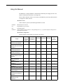
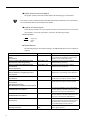
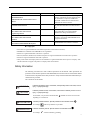
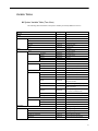
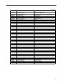
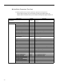
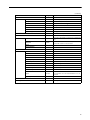
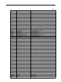
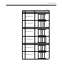
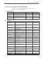
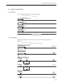
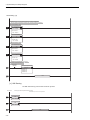
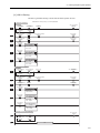
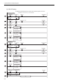
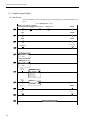
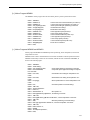
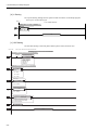
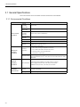
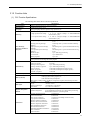
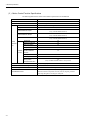
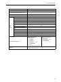
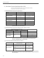
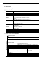
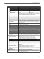
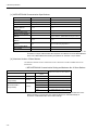
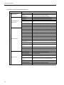
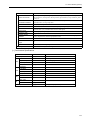
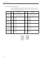
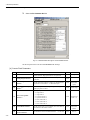
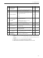
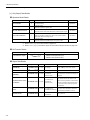
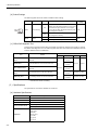
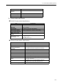
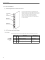
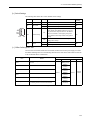
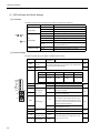
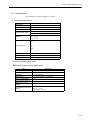
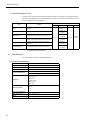
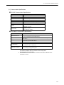
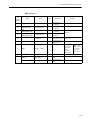
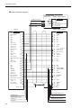
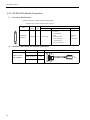
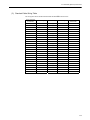
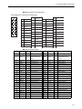
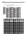
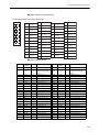
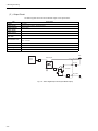
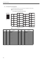
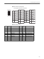
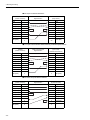
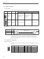
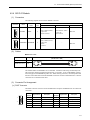
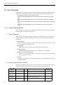
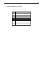
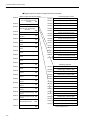
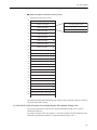
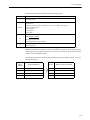
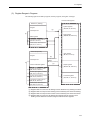
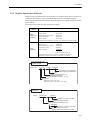
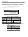
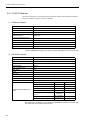
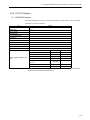
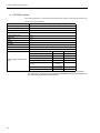
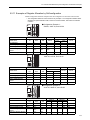
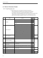
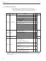
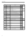
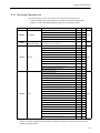
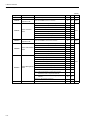
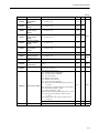
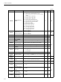
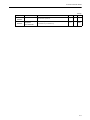
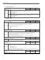
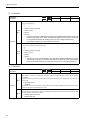
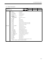
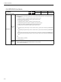
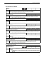
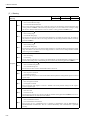
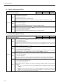
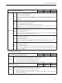
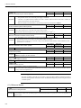
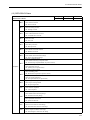
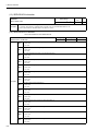
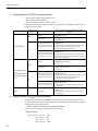
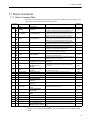
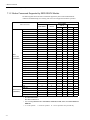
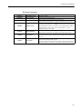
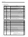
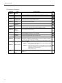
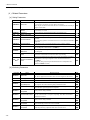
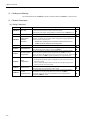
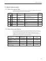
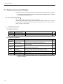
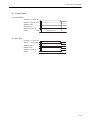
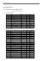
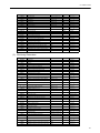
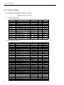
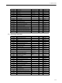
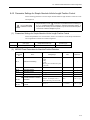
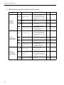
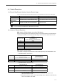
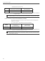
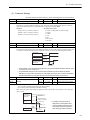
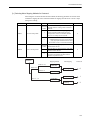
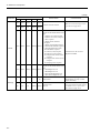
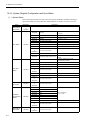
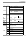
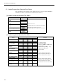
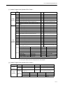
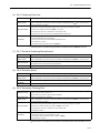
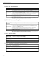
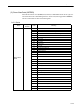
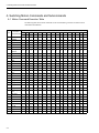
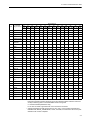
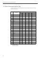
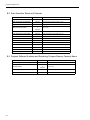
B System Registers Lists
B.2 Scan Execution Status and Calendar
Name
Register No.
Remarks
High-speed Scan Set Value
SW00004
High-speed Scan Set Value (0.1 ms)
High-speed Scan Current Value
SW00005
High-speed Scan Current Value (0.1 ms)
High-speed Scan Maximum Value
SW00006
High-speed Scan Maximum Value (0.1 ms)
Reserved by the system.
SW00007
to
SW00009
(Not used)
Low-speed Scan Set Value
SW00010
Low-speed Scan Set Value (0.1 ms)
Low-speed Scan Current Value
SW00011
Low-speed Scan Current Value (0.1 ms)
Low-speed Scan Maximum Value
SW00012
Low-speed Scan Maximum Value (0.1 ms)
Reserved by the system.
SW00013
(Not used)
Executing Scan Current Value
SW00014
Executing Scan Current Value (0.1 ms)
Calendar: Year
SW00015
1999: 0099 (BCD) (Last two digits only)
Calendar: Month Day
SW00016
December 31: 1231 (BCD)
Calendar: Hours Minutes
SW00017
23 hours 59 minutes: 2359 (BCD)
Calendar: Seconds
SW00018
59 s: 59 (BCD)
Calendar: Day of Week
SW00019
0 to 6: Sun., Mon. to Sat.
B.3 Program Software Numbers and Remaining Program Memory Capacity Name
Name
B-4
Register No.
Remarks
System Program Software Number
SW00020
S†††† (†††† is stored as BCD)
System Number
SW00021
to
SW00025
(Not used)
Remaining Program Memory Capacity
SW00026
Bytes
Total Memory Capacity
SW00028
Bytes
Appendix C
C Initializing the Absolute Encoder................................................A-2
C.1 Initializing Procedures for Σ-III Series SERVOPACKs.............................A-2
C.2 Σ-II SERVOPACK ....................................................................................A-4
C.3 Σ-I SERVOPACK .....................................................................................A-7
C-1
C Initializing the Absolute Encoder
The procedure for initializing an absolute encoder for a Σ-I, Σ-II , or Σ-III SERVOPACK is given
below.
ΠRefer to 9.2.1 System Startup Flowchart on page 9-5 for the procedure for absolute-position
detection.
C.1 Initializing Procedures for Σ-III Series SERVOPACKs
Œ Refer to the following manuals for information on Σ-III series SERVOPACKs:
Σ-III Series SGM…S/SGDS User’s Manual (Manual No. SIEP C80000000…),
Σ-III Series SGM…S/SGDS User’s Manual for MECHATROLINK-II Communications (Manual No.
SIEP C80000011…), and Σ-III Series SGM…S/SGDS Digital Operator Instructions Manual (Manual No. TOEP C80000001…)
Follow the setup procedure below using a Digital Operator.
1.
Press the
Key to display the Utility Function Mode main menu. Use the UP Key
or DOWN Key to select Fn008.
㧮㧮‫ޓޓޓޓޓ‬㧙㧲㨁㧺㧯㨀㧵㧻㧺㧙
㧲㨚㧜㧜㧣
㧲㨚㧜㧜㧤
㧲㨚㧜㧜㧥
㧲㨚㧜㧜㧭
2.
Press the
Key.
The display is switched to the execution display of Fn008 (Absolute encoder multi-turn
reset and encoder alarm reset).
ΠIf the display is not switched and "NO_OP" is displayed in the status display, the Write Prohibited setting (Fn010 = 0001) is set. Check the status and reset. Then clear the Write Prohibited setting.
3.
C-2
Keep pressing the
Key until "PGCL1" is changed to "PGCL5."
C.1 Initializing Procedures for Σ-III Series SERVOPACKs
4.
Press the
Key.
"BB" in the status display changes to "Done."
5.
Press the
Key. The display returns to the Utility Function Mode main menu.
This completes setting up the absolute encoder. Turn the power supply OFF and then back ON to
reset the SERVOPACK.
C-3
C Initializing the Absolute Encoder
C.2 Σ-II SERVOPACK
Œ Refer to the following manuals for information on Σ-II SERVOPACKs.
Σ-II Series SGM†H/SGDH User’s Manual (SIEP S8000 000 05…)
Σ-II Series SGM†/SGDB/SGM†H/SGDM User’s Manual (SIEP S800000 15…)
( 1 ) Initialization Using a Hand-held Digital Operator
1.
Press the DSPL/SET Key to select the Auxiliary Function Mode.
2.
Select parameter Fn008 by pressing the LEFT (<) and RIGHT (>) Keys to select the
digit to be changed and then using the UP (∨) and DOWN (∧) Keys to change the
value of the digit.
3.
Press the DATA/ENTER Key.
The following display will appear.
4.
The rightmost digit will be incremented each time the UP (∨) Key is pressed. Press the
UP (∨) Key several times until “PGCL5” is displayed.
If a mistake is made in the key operation, “nO_OP” will blink on the display for 1 second and
then the display will return to the Auxiliary Function Mode. If this happens, return to step 3,
above, and repeat the operation.
Mistake in Key Operation
UP Key
Blinks for 1 s.
UP Key
Returns to the Auxiliary
Function Mode.
5.
Press the DSPL/SET Key.
The display will change as shown below and the clear operation will be performed for multiturn data for the absolute encoder.
Blinks for 1 s.
C-4
C.2 Σ-II SERVOPACK
This completes initializing the absolute encoder. Reset the SERVOPACK to turn the power supply
OFF and then back ON.
C-5
C Initializing the Absolute Encoder
( 2 ) Initialization Using the Built-in Panel Operator
1.
Press the MODE/SET Key to select the Auxiliary Function Mode.
2.
Press the UP (
3.
Press the DATA/ENTER Key for more than one second.
) and DOWN (
) Keys to select parameter Fn008.
The following display will appear.
4.
The rightmost digit will be incremented each time the UP (
the UP ( ) Key several time until “PGCL5” is displayed.
) Key is pressed. Press
If a mistake is made in the key operation, “nO_OP” will blink on the display for 1 second and
then the display will return to the Auxiliary Function Mode. If this happens, return to step 3,
above, and repeat the operation.
Mistake in Key Operation
UP Key
Blinks for 1 s.
UP Key
Returns to the Auxiliary
Function Mode.
5.
Press the MODE/SET Key.
The display will change as shown below and the clear operation will be performed for multiturn data for the absolute encoder.
Blinks for 1 s.
This completes initializing the absolute encoder. Reset the SERVOPACK to turn the power supply
OFF and then back ON.
C-6
C.3 Σ-I SERVOPACK
C.3 Σ-I SERVOPACK
Œ Refer to the following manuals for information on Σ-I SERVOPACKS.
Σ Series SGM†/SGD User’s Manual (Manual No. SIE-S800-26.3…)
Σ Series SGM†/SGDB High-speed Field Network MECHATROLINK-compatible AC Servo Driver
User’s Manual (Manual No. SIE-S800-26.4…)
( 1 ) Initializing a 12-bit Absolute Encoder
Use the following procedure to initialize a 12-bit absolute encoder.
1.
Properly connect the SERVOPACK, Servomotor, and MP2300.
2.
Disconnect the connector on the encoder end and short-circuit pins 13 and 14 on the
encoder end connector for 2 seconds or more.
13 14
3.
Remove the short piece and insert the connector securely in its original position.
4.
Connect the cables using normal wiring and make sure the encoder battery is connected.
5.
Turn ON the system.
Repeat the procedure starting from step 1 if an Absolute Encoder Alarm occurs, so the system
has been successfully initialized.
C-7
C Initializing the Absolute Encoder
( 2 ) Initializing a 15-bit Absolute Encoder
Use the following procedure to initialize a 15-bit absolute encoder.
1.
Turn OFF the SERVOPACK and MP2300.
2.
Discharge the large-capacity capacitor in the encoder using one of the following methods.
■ At the SERVOPACK End Connector
1) Disconnect the connector on the SERVOPACK end.
2) Use a short piece to short-circuit together connector pins 10 and 13 on the encoder end and
leave the pins short-circuited for at least 2 minutes.
3) Remove the short piece and insert the connector securely in its original position.
■ At the Encoder End Connector
1) Disconnect the connector on the encoder end.
2) Use a short piece to short-circuit together connector pins R and S on the encoder end and
leave the pins short-circuited for at least 2 minutes.
3) Remove the short piece and insert the connector securely in its original position.
SERVOPACK
Key location
Encoder
CN2-1
A
S
R
S
T
R
(White_orange)
(White_orange)
CN2-13
CN2-12
CN2-10
PG cable
Short-circuit here.
3.
Connect the cables using normal wiring and make sure the encoder battery is connected.
4.
Turn ON the system.
Repeat the procedure starting from step 1 if an Absolute Encoder Alarm occurs, so the system
has been successfully initialized.
C-8
Index
INDEX
change feed forward (KFS) - - - - - - - - - - - - - - - - - - - - - - - - - - 7-66
change filter time constant (SCC) - - - - - - - - - - - - - - - - - - - - - 7-58
change filter type (CHG_FILTER) - - - - - - - - - - - - - - - - - - - - - 7-60
change linear acceleration time constant (ACC) - - - - - - - - - - - - 7-54
change linear deceleration time constant (DCC) - - - - - - - - - - - - 7-56
change position loop gain (KPS) - - - - - - - - - - - - - - - - - - - - - - 7-64
change position loop integration time constant (KIS) - - - - - - - - 7-93
change speed loop gain (KVS) - - - - - - - - - - - - - - - - - - - - - - - 7-62
child drawings - - - - - - - - - - - - - - - - - - - - - - - - - - - - - - - - - - - 5-6
clear alarm - - - - - - - - - - - - - - - - - - - - - - - - - - - - - - - - - - - - - 6-25
clear SERVOPACK alarm history (ALMHIST_CLR) - - - - - - - - 7-75
coincidence output and coincidence interrupt functions - - - - - - - 3-38
combination of modules - - - - - - - - - - - - - - - - - - - - - - - - - - - - - 1-4
command abort - - - - - - - - - - - - - - - - - - - - - - - - - - - - - - - - - - 6-30
command buffer for transparent command mode - - - - - - - - - - - 6-46
command execution- - - - - - - - - - - - - - - - - - - - - - - - - - - - - - - - 7-5
command pause - - - - - - - - - - - - - - - - - - - - - - - - - - - - - - - - - 6-30
communication error mask - - - - - - - - - - - - - - - - - - - - - - - - - - 6-20
Communication Modules - - - - - - - - - - - - - - - - - - - - - - - - - - - 3-51
communication settings - - - - - - - - - - - - - - - - - - - - - - - - - - - - - 2-9
connection procedure- - - - - - - - - - - - - - - - - - - - - - - - - - - - - - 4-10
counter function
axis type selection - - - - - - - - - - - - - - - - - - - - - - - - - - - - - 3-40
command settings - - - - - - - - - - - - - - - - - - - - - - - - - - - - - 3-34
electronic gear function - - - - - - - - - - - - - - - - - - - - - - - - - 3-40
Counter Function Details - - - - - - - - - - - - - - - - - - - - - - - - - - - 3-35
counter function of LIO-01 and LIO-02 modules - - - - - - - - - - - 3-28
counter parameters - - - - - - - - - - - - - - - - - - - - - - - - - - - - - - - 3-30
counter fixed parameters - - - - - - - - - - - - - - - - - - - - - - - - 3-30
counter monitor parameters - - - - - - - - - - - - - - - - - - - - - - 3-33
counter setting parameters - - - - - - - - - - - - - - - - - - - - - - - 3-34
creep speed - - - - - - - - - - - - - - - - - - - - - - - - - - - - - - - - - - - - 6-42
Numerics
217IF-01 Module- - - - - - - - - - - - - - - - - - - - - - - - - - - - - - - - connectors - - - - - - - - - - - - - - - - - - - - - - - - - - - - - - - - - 218IF-01 Module- - - - - - - - - - - - - - - - - - - - - - - - - - - - - - - - 260IF-01 Module- - - - - - - - - - - - - - - - - - - - - - - - - - - - - - - - connectors - - - - - - - - - - - - - - - - - - - - - - - - - - - - - - - - - 261IF-01 Module- - - - - - - - - - - - - - - - - - - - - - - - - - - - - - - - connectors - - - - - - - - - - - - - - - - - - - - - - - - - - - - - - - - - 32-bit coordinate system position (DPOS) - - - - - - - - - - - - - - - -
3-54
4-64
3-51
3-57
4-68
3-60
4-71
6-54
A
absolute data - - - - - - - - - - - - - - - - - - - - - - - - - - - - - - - - - - - - - 9-3
absolute encoder - - - - - - - - - - - - - - - - - - - - - - - - - - - - - - - - - - 9-2
initialization - - - - - - - - - - - - - - - - - - - - - - - - - - - - - - - - - - 9-6
initialization (ABS_RST) - - - - - - - - - - - - - - - - - - - - - - - - 7-77
usage - - - - - - - - - - - - - - - - - - - - - - - - - - - - - - - - - - - - - - - 9-8
absolute position at power OFF (lower 2 words) - - - - - - - - 6-46, 6-58
absolute position at power OFF (upper 2 words) - - - - - - - - 6-46, 6-58
absolute position detection
parameter - - - - - - - - - - - - - - - - - - - - - - - - - - - - - - - - - - - - 9-6
Absolute Position Detection for Finite Length Axes - - - - - - - - - - 9-6
absolute position detection system - - - - - - - - - - - - - - - - - - - - - - 9-2
setting procedure - - - - - - - - - - - - - - - - - - - - - - - - - - - - - - - 9-5
acceleration/deceleration filter settings - - - - - - - - - - - - - - - - - - 6-67
acceleration/deceleration settings - - - - - - - - - - - - - - - - - - - - - - 6-65
acceleration/deceleration units - - - - - - - - - - - - - - - - - - - - - - - - 6-27
accessories - - - - - - - - - - - - - - - - - - - - - - - - - - - - - - - - - - - - - - 1-9
AI-01 Module - - - - - - - - - - - - - - - - - - - - - - - - - - - 3-48, 4-53, 4-58
alarm - - - - - - - - - - - - - - - - - - - - - - - - - - - - - - - - - - - - - - - - - 6-49
all program file dump - - - - - - - - - - - - - - - - - - - - - - - - - - - - - - 2-33
all-in-one - - - - - - - - - - - - - - - - - - - - - - - - - - - - - - - - - - - - - - - 3-6
approach speed - - - - - - - - - - - - - - - - - - - - - - - - - - - - - - - - - - 6-42
auxiliary servo constant number size- - - - - - - - - - - - - - - - - - - - 6-45
auxiliary servo user constant - - - - - - - - - - - - - - - - - - - - - 6-45, 6-57
auxiliary servo user constant number - - - - - - - - - - - - - - - 6-45, 6-57
axis selection - - - - - - - - - - - - - - - - - - - - - - - - - - - - - - - - - - - - 9-8
axis type- - - - - - - - - - - - - - - - - - - - - - - - - - - - - - - - - - - 6-18, 6-61
D
daily inspections - - - - - - - - - - - - - - - - - - - - - - - - - - - - - - - - - 12-2
data types- - - - - - - - - - - - - - - - - - - - - - - - - - - - - - - - - - - - - - 5-24
DEC1 + phase-C method - - - - - - - - - - - - - - - - - - - - - - - - - - - 7-20
DEC1 + ZERO signal method - - - - - - - - - - - - - - - - - - - - - - - - 7-23
definition data
self-configuration - - - - - - - - - - - - - - - - - - - - - - - - - - - - - 5-34
deviation abnormal detection error level - - - - - - - - - - - - - - - - - 6-26
deviation abnormal detection value - - - - - - - - - - - - - - - - - - - - 6-36
DeviceNet communication specifications - - - - - - - - - - - - - - - - 3-60
DeviceNet interface - - - - - - - - - - - - - - - - - - - - - - - - - - - - - - - 3-57
digital operator - - - - - - - - - - - - - - - - - - - - - - - - - - - - - - - - - - - 2-4
DIN Rail - - - - - - - - - - - - - - - - - - - - - - - - - - - - - - - - - - - - - - - 1-9
DIN rail mounting - - - - - - - - - - - - - - - - - - - - - - - - - - - - - - - - - 4-2
DIN rail mounting clips - - - - - - - - - - - - - - - - - - - - - - - - - - - - - 4-3
DIP Switch Settings- - - - - - - - - - - - - - - - - - - - - - - - - - - - - - - - 5-2
disable phase reference generation - - - - - - - - - - - - - - - - - - - - - 6-28
DO-01 Module - - - - - - - - - - - - - - - - - - - - - - - - - - 3-47, 4-46, 4-51
drawing execution control - - - - - - - - - - - - - - - - - - - - - - - - - - - 5-7
drawing types - - - - - - - - - - - - - - - - - - - - - - - - - - - - - - - - - - - - 5-6
drive status- - - - - - - - - - - - - - - - - - - - - - - - - - - - - - - - - - - - - 6-47
DWG registers - - - - - - - - - - - - - - - - - - - - - - - - - - - - - - - - - - 5-21
B
backlash compensation - - - - - - - - - - - - - - - - - - - - - - - - - - - - - 6-22
basic module- - - - - - - - - - - - - - - - - - - - - - - - - - - - - - - - - - - - - 3-6
appearance - - - - - - - - - - - - - - - - - - - - - - - - - - - - - - - 1-3, 3-64
connectors - - - - - - - - - - - - - - - - - - - - - - - - - - - - - - - - - - - 4-8
CPU I/O connector - - - - - - - - - - - - - - - - - - - - - - - - - - - - 4-15
power supply connector - - - - - - - - - - - - - - - - - - - - - - - - - - 4-9
Battery - - - - - - - - - - - - - - - - - - - - - - - - - - - - - - - - - - - - - - - - - 1-9
battery
life - - - - - - - - - - - - - - - - - - - - - - - - - - - - - - - - - - - - - - - 12-4
bias speed for exponential acceleration/deceleration filter - - - - - 6-41
Built-in SVB- - - - - - - - - - - - - - - - - - - - - - - - - - - - - - - - - - - - 3-10
E
C
electronic cam - - - - - - - - - - - - - - - - - - - - - - - - - - - - - - - - - electronic gear - - - - - - - - - - - - - - - - - - - - - - - - - - - - - - - - - electronic shaft - - - - - - - - - - - - - - - - - - - - - - - - - - - - - - - - - encoder resolution in pulses/revolution - - - - - - - - - - - - - - - - - -
C pulse only method - - - - - - - - - - - - - - - - - - - - - - - - - - - - - - 7-25
Cables - - - - - - - - - - - - - - - - - - - - - - - - - - - - 1-8, 4-27, 4-35, 4-53
Calculating the Zero Point of the Machine Coordinate System - - 9-19
Index-1
2-52
6-59
2-48
6-23
Index
home return type - - - - - - - - - - - - - - - - - - - - - - - - - - - - - - - - - 6-42
home window - - - - - - - - - - - - - - - - - - - - - - - - - - - - - - - - - - - 6-42
encoder selection - - - - - - - - - - - - - - - - - - - - - - - - - - - - - - - - - - 9-8
encoder type - - - - - - - - - - - - - - - - - - - - - - - - - - - - - - - - - - - - 6-22
error confirmation flow - - - - - - - - - - - - - - - - - - - - - - - - - - - - - 12-6
error status - - - - - - - - - - - - - - - - - - - - - - - - - - - - - - - - - - - - 12-14
Ethernet communication specifications - - - - - - - - - - - - - - - - - - 3-53
Ethernet interface - - - - - - - - - - - - - - - - - - - - - - - - - - - - - - - - - 3-51
Examples of Register Allocation by Self-configuration - - - - - - - 5-43
EX_POSING- - - - - - - - - - - - - - - - - - - - - - - - - - - - - - - - - - - - 7-11
external positioning (EX_POSING) - - - - - - - - - - - - - - - - - - - - 7-11
external positioning move distance - - - - - - - - - - - - - - - - - - - - - 6-43
external positioning signal - - - - - - - - - - - - - - - - - - - - - - - - - - - 6-28
I
I/O Data - - - - - - - - - - - - - - - - - - - - - - - - - - - - - - - - - - - - - - I/O Modules - - - - - - - - - - - - - - - - - - - - - - - - - - - - - - - - - - - infinite length axis - - - - - - - - - - - - - - - - - - - - - - - - - - - - - 9-4,
infinite length axis position control- - - - - - - - - - - - - - - - - 6-21,
ladder program - - - - - - - - - - - - - - - - - - - - - - - - - - - - - - infinite length axis position information LOAD - - - - - - - - - - - INPUT & phase-C pulse method - - - - - - - - - - - - - - - - - - - - - Input Characteristics (A1-01)- - - - - - - - - - - - - - - - - - - - - - - - input circuits
CPU I/O connector - - - - - - - - - - - - - - - - - - - - - - - - - - - LIO-01 module - - - - - - - - - - - - - - - - - - - - - - - - - - - - - - Input Mode - - - - - - - - - - - - - - - - - - - - - - - - - - - - - - - - - - - - INPUT signal for zero point return - - - - - - - - - - - - - - - - - - - - INPUT signal method- - - - - - - - - - - - - - - - - - - - - - - - - - - - - integration reset- - - - - - - - - - - - - - - - - - - - - - - - - - - - - - - - - interpolation (INTERPOLATE) - - - - - - - - - - - - - - - - - - - - - - interpolation override - - - - - - - - - - - - - - - - - - - - - - - - - - - - - -
F
feedback speed - - - - - - - - - - - - - - - - - - - - - - - - - - - - - - - - - - 6-58
feedback speed moving average time constant - - - - - - - - - - - - - 6-23
filter type - - - - - - - - - - - - - - - - - - - - - - - - - - - - - - - - - - - - - - 6-27
finite length axis - - - - - - - - - - - - - - - - - - - - - - - - - - - - - -9-4, 9-10
fixed parameter details - - - - - - - - - - - - - - - - - - - - - - - - - - - - - 6-18
fixed parameter list- - - - - - - - - - - - - - - - - - - - - - - - - - - - - - - - - 6-6
fixed parameter monitor - - - - - - - - - - - - - - - - - - - - - - - - - - - - 6-58
fixed parameter number- - - - - - - - - - - - - - - - - - - - - - - - - - - - - 6-45
fixed parameters- - - - - - - - - - - - - - - - - - - - - - - - - - - - - - - - - - 3-28
fixed parameters for absolute position detection - - - - - - - - - - - - - 9-6
forward external torque limit input - - - - - - - - - - - - - - - - - - - - - 6-25
forward software limit- - - - - - - - - - - - - - - - - - - - - - - - - - - - - - 6-21
forward software limit enabled - - - - - - - - - - - - - - - - - - - - - - - - 6-18
function 1 - - - - - - - - - - - - - - - - - - - - - - - - - - - - - - - - - - - - - - 6-27
function 2 - - - - - - - - - - - - - - - - - - - - - - - - - - - - - - - - - - - - - - 6-28
function 3 - - - - - - - - - - - - - - - - - - - - - - - - - - - - - - - - - - - - - - 6-28
function registers - - - - - - - - - - - - - - - - - - - - - - - - - - - - - - - - - 5-22
function selection 1 - - - - - - - - - - - - - - - - - - - - - - - - - - - - - - - 6-18
function selection 2 - - - - - - - - - - - - - - - - - - - - - - - - - - - - - - - 6-20
functions- - - - - - - - - - - - - - - - - - - - - - - - - - - - - - - - - - - -5-6, 5-20
3-32
3-24
9-13
9-20
9-22
6-25
7-33
3-49
4-16
4-29
4-58
6-28
7-35
6-25
7-36
5-15
J
JEPMC-W2061-†† - - - - - - - - - - - - - - - - - - - - - - - - - - - - - - 4-27
JEPMC-W6060-†† - - - - - - - - - - - - - - - - - - - - - - - - - - 4-35, 4-47
JEPMC-W6080-†† - - - - - - - - - - - - - - - - - - - - - - - - - - - - - - 4-53
JOG operation (FEED) - - - - - - - - - - - - - - - - - - - - - - - - - - - - - 7-44
jog/step direction - - - - - - - - - - - - - - - - - - - - - - - - - - - - - - - - - 6-30
L
L drawing- - - - - - - - - - - - - - - - - - - - - - - - - - - - - - - - - - - - - - 2-58
L06 drawing - - - - - - - - - - - - - - - - - - - - - - - - - - - - - - - - - - - - 2-58
ladder drawings (DWG) - - - - - - - - - - - - - - - - - - - - - - - - - - - - - 5-6
latch (LATCH) - - - - - - - - - - - - - - - - - - - - - - - - - - - - - - - - - - 7-40
latch input signal type- - - - - - - - - - - - - - - - - - - - - - - - - - - - - - 6-28
latch request - - - - - - - - - - - - - - - - - - - - - - - - - - - - - - - - - - - - 6-24
latch zone enable - - - - - - - - - - - - - - - - - - - - - - - - - - - - - - - - - 6-30
latch zone lower limit setting - - - - - - - - - - - - - - - - - - - - - - - - - 6-37
latch zone upper limit setting - - - - - - - - - - - - - - - - - - - - - - - - - 6-37
leading register numbers - - - - - - - - - - - - - - - - - - - - - - - - - - - - - 6-2
LED
217IF-01 Module- - - - - - - - - - - - - - - - - - - - - - - - - - - - - - 3-55
218IF-01 Module- - - - - - - - - - - - - - - - - - - - - - - - - - - - - - 3-51
260IF-01 Module- - - - - - - - - - - - - - - - - - - - - - - - - - - - - - 3-58
261IF-01 Module- - - - - - - - - - - - - - - - - - - - - - - - - - - - - - 3-61
Basic Module - - - - - - - - - - - - - - - - - - - - - - - - - - - - - - - - - 3-7
LIO-01 Module - - - - - - - - - - - - - - - - - - - - - - - - - - - - - - - 3-26
LED indicator details - - - - - - - - - - - - - - - - - - - - - - - - - - - - - - - 5-5
LED Indicators
AI-01- - - - - - - - - - - - - - - - - - - - - - - - - - - - - - - - - - - - - - 3-48
DO-01 - - - - - - - - - - - - - - - - - - - - - - - - - - - - - - - - - - - - - 3-48
SVA-01 - - - - - - - - - - - - - - - - - - - - - - - - - - - - - - - - - - - - 3-20
SVB-01 - - - - - - - - - - - - - - - - - - - - - - - - - - - - - - - - - - - - 3-15
LED indicators - - - - - - - - - - - - - - - - - - - - - - - - - - - - - - - - - - 12-7
linear acceleration time- - - - - - - - - - - - - - - - - - - - - - - - - - - - - 6-40
linear deceleration time- - - - - - - - - - - - - - - - - - - - - - - - - - - - - 6-40
LIO-01 Module - - - - - - - - - - - - - - - - - - - - - - - - - - - - - - - - - - 3-24
LIO-02 Module - - - - - - - - - - - - - - - - - - - - - - - - - - - - - - - - - - 4-33
LIO-04 Module - - - - - - - - - - - - - - - - - - - - - - - - - - - - - - - - - - 4-42
LIO-04/LIO-05 Module - - - - - - - - - - - - - - - - - - - - - - - - - - - - 4-34
LIO-04/LIO-05 Modules- - - - - - - - - - - - - - - - - - - - - - - - - - - - 3-44
G
gain switch - - - - - - - - - - - - - - - - - - - - - - - - - - - - - - - - - - - - - 6-26
gear ratio (motor) - - - - - - - - - - - - - - - - - - - - - - - - - - - - - - - - - 6-20
grandchild drawings - - - - - - - - - - - - - - - - - - - - - - - - - - - - - - - - 5-6
group folders - - - - - - - - - - - - - - - - - - - - - - - - - - - - - - - - - - - - 2-15
creating - - - - - - - - - - - - - - - - - - - - - - - - - - - - - - - - - - - - 2-15
groups - - - - - - - - - - - - - - - - - - - - - - - - - - - - - - - - - - - - - - - - 5-11
H
H drawing - - - - - - - - - - - - - - - - - - - - - - - - - - - - - - - - - - - - - - 2-39
H01 drawing - - - - - - - - - - - - - - - - - - - - - - - - - - - - - - - - - - - - 2-39
H02 drawing - - - - - - - - - - - - - - - - - - - - - - - - - - - - - - - - - - - - 2-40
H02.01 drawing - - - - - - - - - - - - - - - - - - - - - - - - - - - - - - - - - - 2-41
H02.02 drawing - - - - - - - - - - - - - - - - - - - - - - - - - - - - - - - - - - 2-42
H06.01 drawing - - - - - - - - - - - - - - - - - - - - - - - - - - - - - - - - - - 2-50
H06.02 drawing - - - - - - - - - - - - - - - - - - - - - - - - - - - - - - - - - - 2-55
hardware specifications
217IF-01 Module - - - - - - - - - - - - - - - - - - - - - - - - - - - - - - 3-56
218IF-01 Module - - - - - - - - - - - - - - - - - - - - - - - - - - - - - - 3-52
260IF-01 Module - - - - - - - - - - - - - - - - - - - - - - - - - - - - - - 3-59
261IF-01 Module - - - - - - - - - - - - - - - - - - - - - - - - - - - - - - 3-62
Basic Module - - - - - - - - - - - - - - - - - - - - - - - - - - - - - - - - - 3-9
MP2300 - - - - - - - - - - - - - - - - - - - - - - - - - - - - - - - - - - - - - 3-2
home direction- - - - - - - - - - - - - - - - - - - - - - - - - - - - - - - - - - - 6-30
HOME LS & phase-C pulse method - - - - - - - - - - - - - - - - - - - - 7-28
HOME LS signal method - - - - - - - - - - - - - - - - - - - - - - - - - - - 7-30
home offset - - - - - - - - - - - - - - - - - - - - - - - - - - - - - - - - - - - - - 6-42
Index-2
Index
motion subcommand status - - - - - - - - - - - - - - - - - - - - - - - - - - 6-52
motion subcommands - - - - - - - - - - - - - - - - - - - - - - - - - 6-31, 7-95
execution table - - - - - - - - - - - - - - - - - - - - - - - - - - - - - - - - A-4
motor type - - - - - - - - - - - - - - - - - - - - - - - - - - - - - - - - - - - - - 6-57
mounting MP2300- - - - - - - - - - - - - - - - - - - - - - - - - - - - - - - - - 4-2
MP2300 Fixed Parameters for Absolute Position Detection - - - - 9-15
MP2500
mode switch 1 (S1) - - - - - - - - - - - - - - - - - - - - - - - - - - - - - 5-2
mode switch 2 (S2) - - - - - - - - - - - - - - - - - - - - - - - - - - - - - 5-2
MPE720 - - - - - - - - - - - - - - - - - - - - - - - - - - - - - - - - - - - - - - - 2-7
MPE720 (Embedded) startup - - - - - - - - - - - - - - - - - - - - - - - - - 2-7
multiturn limit setting - - - - - - - - - - - - - - - - - - - - - - - - - - - - - - 9-9
LIO-05 Module - - - - - - - - - - - - - - - - - - - - - - - - - - - - - - - - - - 4-44
loading
individual - - - - - - - - - - - - - - - - - - - - - - - - - - - - - - - - - - - 2-25
log off - - - - - - - - - - - - - - - - - - - - - - - - - - - - - - - - - - - - - - - - 2-35
M
machine coordinate feedback position (APOS) - - - - - - - - - - - - - 6-54
machine coordinate latch position (LPOS) - - - - - - - - - - - - - - - - 6-54
machine coordinate system - - - - - - - - - - - - - - - - - - - - - - - - - - 6-54
machine coordinate system position (MPOS) - - - - - - - - - - - - - - 6-54
machine coordinate target position (TPOS) - - - - - - - - - - - - - - - 6-53
machine lock- - - - - - - - - - - - - - - - - - - - - - - - - - - - - - - - - - - - 6-24
manual operation - - - - - - - - - - - - - - - - - - - - - - - - - - - - - - - - - 2-36
maximum number of absolute encoder turns - - - - - - - - - - - - - - 6-23
maximum value of rotary counter - - - - - - - - - - - - - - - - - - - - - - 6-21
MECHATROLINK
cables - - - - - - - - - - - - - - - - - - - - - - - - - - - - - - - - - - - - - 4-11
connector - - - - - - - - - - - - - - - - - - - - - - - - - - - - - - - - - - - 4-10
SERVOPACKs - - - - - - - - - - - - - - - - - - - - - - - - - - - - - - - - 1-7
terminator connections - - - - - - - - - - - - - - - - - - - - - - - - - - 4-13
mode 1- - - - - - - - - - - - - - - - - - - - - - - - - - - - - - - - - - - - - - - - 6-26
mode 2- - - - - - - - - - - - - - - - - - - - - - - - - - - - - - - - - - - - - - - - 6-26
modularized position at power OFF (lower 2 words) - - - - - 6-46, 6-58
modularized position at power OFF (upper 2 words) - - - - - 6-46, 6-58
Module - - - - - - - - - - - - - - - - - - - - - - 3-14, 3-16, 3-21, 3-45, 5-33
module information - - - - - - - - - - - - - - - - - - - - - - - - - - - - - - 12-20
Module Specifications - - - - - - - - - - - - - - - - - - - - - - - - - - - - - 3-45
SVA-01 - - - - - - - - - - - - - - - - - - - - - - - - - - - - - - - - - - - - 3-21
SVB-01 - - - - - - - - - - - - - - - - - - - - - - - - - - - - - - - - - - - - 3-16
monitor 2 - - - - - - - - - - - - - - - - - - - - - - - - - - - - - - - - - - - - - - 6-44
monitor 2 enabled - - - - - - - - - - - - - - - - - - - - - - - - - - - - - - - - 6-26
monitor 4 - - - - - - - - - - - - - - - - - - - - - - - - - - - - - - - - - - - - - - 6-44
monitor SERVOPACK alarm history (ALM_HIST) - - - - - - - - - 7-73
monitor SERVOPACK alarms (ALM_MON) - - - - - - - - - - - - - - 7-72
monitor status (SMON) - - - - - - - - - - - - - - - - - - - - - - - - - - - 7-100
monitoring parameter details - - - - - - - - - - - - - - - - - - - - - - - - - 6-46
monitoring parameter list - - - - - - - - - - - - - - - - - - - - - - - - - - - 6-13
motion command options - - - - - - - - - - - - - - - - - - - - - - - - - - - 6-30
motion command response codes - - - - - - - - - - - - - - - - - - - - - - 6-51
motion command table - - - - - - - - - - - - - - - - - - - - - - - - - - - - - - 7-3
motion commands - - - - - - - - - - - - - - - - - - - - - - - - - - - - - - - - 6-29
execution table - - - - - - - - - - - - - - - - - - - - - - - - - - - - - - - - A-2
motion commands supported by SERVOPACK models - - - - - - - - 7-4
motion control function specifications- - - - - - - - - - - - - - - - - - - - 3-4
motion errors - - - - - - - - - - - - - - - - - - - - - - - - - - - - - - - - - - 12-22
motion fixed parameter
setting - - - - - - - - - - - - - - - - - - - - - - - - - - - - - - - - - - - - - 2-28
motion parameter
setting window - - - - - - - - - - - - - - - - - - - - - - - - - - - - - - - - 6-4
motion parameters
register numbers - - - - - - - - - - - - - - - - - - - - - - - - - - - - - - - 6-2
setting example - - - - - - - - - - - - - - - - - - - - - - - - - - - - - - - 6-59
motion program alarms- - - - - - - - - - - - - - - - - - - - - - - - - - - - 12-21
motion programs - - - - - - - - - - - - - - - - - - - - -2-43, 2-47, 5-10, 5-12
control signals- - - - - - - - - - - - - - - - - - - - - - - - - - - - - - - - 5-14
execution information - - - - - - - - - - - - - - - - - - - - - - - - - - 5-16
ladder programs for control - - - - - - - - - - - - - - - - - - - - - - - 5-18
MSEE registers - - - - - - - - - - - - - - - - - - - - - - - - - - - - - - - 5-12
S registers - - - - - - - - - - - - - - - - - - - - - - - - - - - - - - - - - - 5-12
status bits - - - - - - - - - - - - - - - - - - - - - - - - - - - - - - - - - - - 5-13
motion subcommand response code - - - - - - - - - - - - - - - - - - - - 6-51
N
negative overtravel - - - - - - - - - - - - - - - - - - - - - - - - - - - - - - - 6-19
network servo I/O monitor - - - - - - - - - - - - - - - - - - - - - - - - - - 6-56
network servo status - - - - - - - - - - - - - - - - - - - - - - - - - - - - - - 6-55
network servo user monitor information - - - - - - - - - - - - - - - - - 6-57
no command (NOP)- - - - - - - - - - - - - - - - - - - - - - - - - - - - - - - 7-96
NOT & phase-C pulse method- - - - - - - - - - - - - - - - - - - - - - - - 7-31
NOT signal method - - - - - - - - - - - - - - - - - - - - - - - - - - - - - - - 7-32
number of decimal places - - - - - - - - - - - - - - - - - - - - - - - - - - - 6-20
number of encoder resolution - - - - - - - - - - - - - - - - - - - - - - - - - 9-8
O
Offset and Gain Setting (AI-01)- - - - - - - - - - - - - - - - - - - - - - - 4-59
online logon - - - - - - - - - - - - - - - - - - - - - - - - - - - - - - - - - - - - 2-19
operation
starting - - - - - - - - - - - - - - - - - - - - - - - - - - - - - - - - - - - - - 5-4
stopping- - - - - - - - - - - - - - - - - - - - - - - - - - - - - - - - - - - - - 5-4
operation errors
processing drawings - - - - - - - - - - - - - - - - - - - - - - - - - - - - 5-6
option slot configuration- - - - - - - - - - - - - - - - - - - - - - - - - - - - - 3-6
Option Slot Cover - - - - - - - - - - - - - - - - - - - - - - - - - - - - - - - - - 1-9
optional modules- - - - - - - - - - - - - - - - - - - - - - - - - - - - - - - - - - 4-5
appearance - - - - - - - - - - - - - - - - - - - - - - - - - - - - - - - - - - - 1-3
installing - - - - - - - - - - - - - - - - - - - - - - - - - - - - - - - - - - - - 4-7
removing - - - - - - - - - - - - - - - - - - - - - - - - - - - - - - - - - - - - 4-5
replacing and adding - - - - - - - - - - - - - - - - - - - - - - - - - - - - 4-5
order folders- - - - - - - - - - - - - - - - - - - - - - - - - - - - - - - - - - - - 2-16
output circuit
CPU I/O connector - - - - - - - - - - - - - - - - - - - - - - - - - - - - 4-17
LIO-01 Module- - - - - - - - - - - - - - - - - - - - - - - - - - - - - - - 4-30
over range parameter number - - - - - - - - - - - - - - - - - - - - - - - - 6-47
overtravel function - - - - - - - - - - - - - - - - - - - - - - - - - - - - - - - 10-8
P
Parameter Settings for Simple Absolute Infinite Length Position Control
9-15
parameters
automatic updating - - - - - - - - - - - - - - - - - - - - - - - - - - - - 11-2
updating during self-configuration - - - - - - - - - - - - - - - - - - 11-5
parent drawings - - - - - - - - - - - - - - - - - - - - - - - - - - - - - - - - - - 5-6
password - - - - - - - - - - - - - - - - - - - - - - - - - - - - - - - - - - - - - - 2-22
phase compensation- - - - - - - - - - - - - - - - - - - - - - - - - - - - - - - 6-37
phase compensation type with an electronic cam - - - - - - - - - - - 6-31
phase control - - - - - - - - - - - - - - - - - - - - - - - - - - - - - - - - - - - - 8-6
control block diagram - - - - - - - - - - - - - - - - - - - - - - - - - - - 8-8
phase references (PHASE) - - - - - - - - - - - - - - - - - - - - - - - - - - 7-89
phase-C method - - - - - - - - - - - - - - - - - - - - - - - - - - - - - - - - - 7-24
PI latch function - - - - - - - - - - - - - - - - - - - - - - - - - - - - - - - - - 3-39
Index-3
Index
reverse software limit - - - - - - - - - - - - - - - - - - - - - - - - - - - - - reverse software limit enabled - - - - - - - - - - - - - - - - - - - - - - - RS-232C communication specifications - - - - - - - - - - - - - - - - RS422/485 communication specifications - - - - - - - - - - - - - - - RUN commands - - - - - - - - - - - - - - - - - - - - - - - - - - - - - - - - run mode - - - - - - - - - - - - - - - - - - - - - - - - - - - - - - - - - - - - - -
Pin Arrangement
AI-01 Module - - - - - - - - - - - - - - - - - - - - - - - - - - - - - - - - 4-54
DO-01 Module - - - - - - - - - - - - - - - - - - - - - - - - - - - - - - - 4-48
LIO-04 Module - - - - - - - - - - - - - - - - - - - - - - - - - - - - - - - 4-36
LIO-05 Module - - - - - - - - - - - - - - - - - - - - - - - - - - - - - - - 4-38
pin arrangement
CPU I/O connector - - - - - - - - - - - - - - - - - - - - - - - - - - - - - 4-15
DeviceNet connector - - - - - - - - - - - - - - - - - - - - - - - - - - - 4-69
Ethernet connector (10Base-T) - - - - - - - - - - - - - - - - - - - - - 4-61
LIO-01 Module connector - - - - - - - - - - - - - - - - - - - - - - - - 4-28
PORT connector - - - - - - - - - - - - - - - - - - - - - - - - - - - - - - 4-61
PROFIBUS connector- - - - - - - - - - - - - - - - - - - - - - - - - - - 4-72
RS422/485 connector - - - - - - - - - - - - - - - - - - - - - - - - - - - 4-65
PLC folders- - - - - - - - - - - - - - - - - - - - - - - - - - - - - - - - - - - - - 2-17
creating - - - - - - - - - - - - - - - - - - - - - - - - - - - - - - - - - - - - 2-17
PLC function specifications - - - - - - - - - - - - - - - - - - - - - - - - - - - 3-3
position complete timeout - - - - - - - - - - - - - - - - - - - - - - - - - - - 6-37
position completed width- - - - - - - - - - - - - - - - - - - - - - - - - - - - 6-35
position control - - - - - - - - - - - - - - - - - - - - - - - - - - - - - - -2-43, 8-2
control block diagram - - - - - - - - - - - - - - - - - - - - - - - - - - - - 8-4
position error (PERR) - - - - - - - - - - - - - - - - - - - - - - - - - - - - - - 6-54
position integration time constant - - - - - - - - - - - - - - - - - - - - - - 6-38
position loop gain- - - - - - - - - - - - - - - - - - - - - - - - - - - - - - - - - 6-38
position management status - - - - - - - - - - - - - - - - - - - - - - - - - - 6-52
position reference- - - - - - - - - - - - - - - - - - - - - - - - - - - - - - - - - 6-62
position reference setting- - - - - - - - - - - - - - - - - - - - - - - - - - - - 6-34
position reference type - - - - - - - - - - - - - - - - - - - - - - - - - - - - - 6-30
positioning (POSING)- - - - - - - - - - - - - - - - - - - - - - - - - - - - - - - 7-5
positioning completed width 2 - - - - - - - - - - - - - - - - - - - - - - - - 6-36
positive overtravel - - - - - - - - - - - - - - - - - - - - - - - - - - - - - - - - 6-19
positive side limiting torque setting at the speed reference - - - - - 6-33
POSMAX number of turns - - - - - - - - - - - - - - - - - - - - - - - - - - 6-54
POSMAX preset - - - - - - - - - - - - - - - - - - - - - - - - - - - - - - - - - 6-25
POT & C pulse method - - - - - - - - - - - - - - - - - - - - - - - - - - - - - 7-26
POT signal method- - - - - - - - - - - - - - - - - - - - - - - - - - - - - - - - 7-27
preset data of POSMAX turn - - - - - - - - - - - - - - - - - - - - - - - - - 6-43
PRM_RD - - - - - - - - - - - - - - - - - - - - - - - - - - - - - - - - - - - - - - 7-97
PROFIBUS communication specifications - - - - - - - - - - - - - - - - 3-63
PROFIBUS ID- - - - - - - - - - - - - - - - - - - - - - - - - - - - - - - - - - - 3-63
PROFIBUS interface - - - - - - - - - - - - - - - - - - - - - - - - - - - - - - 3-60
program memory
remaining capacity - - - - - - - - - - - - - - - - - - - - - - - - - - - - - -B-4
programming device-related equipment - - - - - - - - - - - - - - - - - - - 2-4
pulse count function - - - - - - - - - - - - - - - - - - - - - - - - - - - - - - - 3-37
pulse counting modes - - - - - - - - - - - - - - - - - - - - - - - - - - - - - - 3-35
pulse distribution - - - - - - - - - - - - - - - - - - - - - - - - - - - - - - - - - 7-16
pulse input circuit
LIO-01 Module - - - - - - - - - - - - - - - - - - - - - - - - - - - - - - - 4-31
6-21
6-19
3-53
3-57
6-24
6-18
S
S registers
monitoring execution information - - - - - - - - - - - - - - - - - - 5-15
sample programs
checking operation- - - - - - - - - - - - - - - - - - - - - - - - - - - - - 2-36
saving to flash memory- - - - - - - - - - - - - - - - - - - - - - - - - - - - - 2-31
scan execution status - - - - - - - - - - - - - - - - - - - - - - - - - - - - - - - B-4
scan processing drawing - - - - - - - - - - - - - - - - - - - - - - - - - - - - - 5-7
scan time
setting and changing - - - - - - - - - - - - - - - - - - - - - - - - - - - 11-8
S-curve acceleration time - - - - - - - - - - - - - - - - - - - - - - - - - - - 6-41
secondary speed compensation - - - - - - - - - - - - - - - - - - - - - - - 6-33
segment distribution processing - - - - - - - - - - - - - - - - - - - - - - - 6-19
self-configuration - - - - - - - - - - - - - - - - - - - - 2-19, 5-4, 5-28, 5-43
217IF-01 Module- - - - - - - - - - - - - - - - - - - - - - - - - - - - - - 5-39
218IF-01 Module- - - - - - - - - - - - - - - - - - - - - - - - - - - - - - 5-38
260IF-01 Module- - - - - - - - - - - - - - - - - - - - - - - - - - - - - - 5-41
261IF-01 Module- - - - - - - - - - - - - - - - - - - - - - - - - - - - - - 5-42
LIO-01 Module - - - - - - - - - - - - - - - - - - - - - - - - - - - - - - - 5-36
method- - - - - - - - - - - - - - - - - - - - - - - - - - - - - - - - - - - - - - 2-5
self-diagnosis
online - - - - - - - - - - - - - - - - - - - - - - - - - - - - - - - - - - - - - - 5-4
self-diagnosis at startup - - - - - - - - - - - - - - - - - - - - - - - - - - - - - 5-4
serial interfaces - - - - - - - - - - - - - - - - - - - - - - - - - - - - - - - - - - 3-54
servo alarm code - - - - - - - - - - - - - - - - - - - - - - - - - - - - - - - - - 6-56
servo alarm monitor number - - - - - - - - - - - - - - - - - - - - - - - - - 6-45
servo constant number - - - - - - - - - - - - - - - - - - - - - - - - - 6-45, 6-57
servo constant number size - - - - - - - - - - - - - - - - - - - - - - - - - - 6-45
servo driver error codes - - - - - - - - - - - - - - - - - - - - - - - - - - - 12-28
servo module command status - - - - - - - - - - - - - - - - - - - - - - - - 6-51
servo ON - - - - - - - - - - - - - - - - - - - - - - - - - - - - - - - - - - - - - - 6-24
servo user constant- - - - - - - - - - - - - - - - - - - - - - - - - - - - 6-45, 6-57
servo user monitor - - - - - - - - - - - - - - - - - - - - - - - - - - - - - - - - 6-44
servo user monitor 2- - - - - - - - - - - - - - - - - - - - - - - - - - - - - - - 6-57
servo user monitor 3- - - - - - - - - - - - - - - - - - - - - - - - - - - - - - - 6-57
servo user monitor 4- - - - - - - - - - - - - - - - - - - - - - - - - - - - - - - 6-57
SERVOPACK initialization - - - - - - - - - - - - - - - - - - - - - - - - - - - 2-4
SERVOPACK parameters
absolute position detection - - - - - - - - - - - - - - - - - - - - - - - - 9-7
setting parameter details - - - - - - - - - - - - - - - - - - - - - - - - - - - - 6-24
setting parameter list - - - - - - - - - - - - - - - - - - - - - - - - - - - - - - - 6-8
simple ABS infinite axis - - - - - - - - - - - - - - - - - - - - - - - - - - - - 6-19
Simple Absolute Infinite Length Position Control - - - - - - - - - - - 9-13
software limit function - - - - - - - - - - - - - - - - - - - - - - - - - - - - 10-12
speed amends - - - - - - - - - - - - - - - - - - - - - - - - - - - - - - - - - - - 6-38
speed control- - - - - - - - - - - - - - - - - - - - - - - - - - - - - - - - - - - - 8-14
control block diagram- - - - - - - - - - - - - - - - - - - - - - - - - - - 8-16
speed feed forward compensation- - - - - - - - - - - - - - - - - - - - - - 6-38
speed integration time constant - - - - - - - - - - - - - - - - - - - - - - - 6-39
speed limit at torque/thrust reference - - - - - - - - - - - - - - - - - - - 6-32
speed loop gain - - - - - - - - - - - - - - - - - - - - - - - - - - - - - - - - - - 6-38
speed loop P/PI switch - - - - - - - - - - - - - - - - - - - - - - - - - - - - - 6-26
speed override - - - - - - - - - - - - - - - - - - - - - - - - - - - - - - - - - - - 6-34
speed reference - - - - - - - - - - - - - - - - - - - - - - - - - - - - - - - - - - 6-63
R
rated speed - - - - - - - - - - - - - - - - - - - - - - - - - - - - - - - - - - - - - 6-23
read fixed parameters (FIXPRM_RD) - - - - - - - - - - - - - - - - - - 7-102
read SERVOPACK parameter (PRM_RD) - - - - - - - - - - - - 7-68, 7-97
reference unit- - - - - - - - - - - - - - - - - - - - - - - - - - - - - - - - - - - - 6-59
reference unit setting- - - - - - - - - - - - - - - - - - - - - - - - - - - - - - - 6-20
reference units per revolution - - - - - - - - - - - - - - - - - - - - - - - - - 6-20
register types - - - - - - - - - - - - - - - - - - - - - - - - - - - - - - - - - - - - 5-21
regular inspections - - - - - - - - - - - - - - - - - - - - - - - - - - - - - - - - 12-3
reset absolute encoder (ABS_RST) - - - - - - - - - - - - - - - - - - - - - 7-77
response buffer for transparent command mode - - - - - - - - - - - - 6-58
reverse external torque limit input- - - - - - - - - - - - - - - - - - - - - - 6-25
Index-4
Index
U
setting - - - - - - - - - - - - - - - - - - - - - - - - - - - - - - - - - - - - - 6-33
speed reference (VELO) - - - - - - - - - - - - - - - - - - - - - - - - - - - - 7-80
speed reference output monitor - - - - - - - - - - - - - - - - - - - - - - - 6-54
speed unit - - - - - - - - - - - - - - - - - - - - - - - - - - - - - - - - - - - - - - 6-27
Standard Cable Wiring Table - - - - - - - - - - - - - - - - - 4-27, 4-35, 4-53
standard cables - - - - - - - - - - - - - - - - - - - - - - - - - - - - - - - - - - 4-24
startup sequence - - - - - - - - - - - - - - - - - - - - - - - - - - - - - - - - - - 5-2
step distance - - - - - - - - - - - - - - - - - - - - - - - - - - - - - - - - - - - - 6-43
STEP operation (STEP) - - - - - - - - - - - - - - - - - - - - - - - - - - - - 7-48
store - - - - - - - - - - - - - - - - - - - - - - - - - - - - - - - - - - - - - - - - - 6-46
SVA-01 Module - - - - - - - - - - - - - - - - - - - - - - - - - - - - - 3-19, 4-22
SERVOPACK connection cables - - - - - - - - - - - - - - - - - - - 4-24
standard cables - - - - - - - - - - - - - - - - - - - - - - - - - - - - - - - 4-24
SVB-01 Module - - - - - - - - - - - - - - - - - - - - - - - - - - - - - 3-14, 4-19
switch settings- - - - - - - - - - - - - - - - - - - - - - - - - - - - - - - - 3-15
switch
217IF-01 Module- - - - - - - - - - - - - - - - - - - - - - - - - - - - - - 3-55
218IF-01 Module- - - - - - - - - - - - - - - - - - - - - - - - - - - - - - 3-51
260IF-01 Module- - - - - - - - - - - - - - - - - - - - - - - - - - - - - - 3-58
261IF-01 Module- - - - - - - - - - - - - - - - - - - - - - - - - - - - - - 3-61
Basic Module - - - - - - - - - - - - - - - - - - - - - - - - - - - - - - - - - 3-7
LIO-01 Module - - - - - - - - - - - - - - - - - - - - - - - - - - - - - - - 3-26
System Configuration- - - - - - - - - - - - - - - - - - - - - - - - - - - - - - - 2-3
system error status - - - - - - - - - - - - - - - - - - - - - - - - - - - - - - - 12-15
system I/O error status - - - - - - - - - - - - - - - - - - - - - - - - - - - - 12-18
system program software number - - - - - - - - - - - - - - - - - - - - - - - B-4
system registers
accessing - - - - - - - - - - - - - - - - - - - - - - - - - - - - - - - - - - 12-10
configuration - - - - - - - - - - - - - - - - - - - - - - - - - - - - - - - 12-14
system service registers - - - - - - - - - - - - - - - - - - - - - - - - - - - - - B-2
system services
execution status - - - - - - - - - - - - - - - - - - - - - - - - - - - - - - 12-18
system startup - - - - - - - - - - - - - - - - - - - - - - - - - - - - - - - - - - - - 2-2
adding electric devices - - - - - - - - - - - - - - - - - - - - - - - - - - 2-61
first - - - - - - - - - - - - - - - - - - - - - - - - - - - - - - - - - - - - - - - 2-59
procedure - - - - - - - - - - - - - - - - - - - - - - - - - - - - - - - - - - - - 2-2
replacing electric devices - - - - - - - - - - - - - - - - - - - - - - - - 2-63
self-configuration - - - - - - - - - - - - - - - - - - - - - - - - - - - - - 2-59
system status- - - - - - - - - - - - - - - - - - - - - - - - - - - - - - - - - - - 12-14
system variable table - - - - - - - - - - - - - - - - - - - - - - - - - - - - - - - - xi
system work number - - - - - - - - - - - - - - - - - - - - - - - - - - - - - - 5-15
user constants self-writing function - - - - - - - - - - - - - - - - - - - - 6-19
user definition files - - - - - - - - - - - - - - - - - - - - - - - - - - - - - - - 11-7
user name - - - - - - - - - - - - - - - - - - - - - - - - - - - - - - - - - - - - - 2-22
user operation
error status - - - - - - - - - - - - - - - - - - - - - - - - - - - - - - - - - -12-16
user program errors
correcting - - - - - - - - - - - - - - - - - - - - - - - - - - - - - - - - - -12-13
user programs - - - - - - - - - - - - - - - - - - - - - - - - - - - - - - - - - - - - 5-6
V
variable tables- - - - - - - - - - - - - - - - - - - - - - - - - - - - - - - - - - - - - xi
vertical axes
control- - - - - - - - - - - - - - - - - - - - - - - - - - - - - - - - - - - - - 10-2
virtual motion module
SVR - - - - - - - - - - - - - - - - - - - - - - - - - - - - - - - - - - - - - - 3-11
W
warning - - - - - - - - - - - - - - - - - - - - - - - - - - - - - - - - - - - - - - WDT error mask - - - - - - - - - - - - - - - - - - - - - - - - - - - - - - - - work coordinate system offset - - - - - - - - - - - - - - - - - - - - - - - write SERVOPACK parameter (PRM_WR)- - - - - - - - - - - 7-70,
6-48
6-20
6-43
7-98
Z
zero point of the machine coordinate system
calculating - - - - - - - - - - - - - - - - - - - - - - - - - - - - - - - - - zero point offset - - - - - - - - - - - - - - - - - - - - - - - - - - - - - - - - zero point return (ZRET) - - - - - - - - - - - - - - - - - - - - - - - - - - zero point return method
selecting - - - - - - - - - - - - - - - - - - - - - - - - - - - - - - - - - - zero point setting- - - - - - - - - - - - - - - - - - - - - - - - - - - - - - - - ZERO signal method - - - - - - - - - - - - - - - - - - - - - - - - - - - - - -
T
target position (CPOS) - - - - - - - - - - - - - - - - - - - - - - - - - - - - - 6-53
target position difference monitor - - - - - - - - - - - - - - - - - - - - - - 6-54
Temperature Characteristics (LIO-04/LIO-05) - - - - - - - - - - - - - 3-46
torque (thrust) reference monitor - - - - - - - - - - - - - - - - - - - - - - 6-58
torque control - - - - - - - - - - - - - - - - - - - - - - - - - - - - - - - - - - - 8-10
control block diagram- - - - - - - - - - - - - - - - - - - - - - - - - - - 8-12
torque feed forward compensation - - - - - - - - - - - - - - - - - - - - - 6-32
torque reference (TRQ)- - - - - - - - - - - - - - - - - - - - - - - - - - - - - 7-84
torque unit selection - - - - - - - - - - - - - - - - - - - - - - - - - - - - - - - 6-27
torque/thrust reference - - - - - - - - - - - - - - - - - - - - - - - - - - - - - 6-32
transfer
all - - - - - - - - - - - - - - - - - - - - - - - - - - - - - - - - - - - - - - - - 2-23
transmission errors
actions to be taken - - - - - - - - - - - - - - - - - - - - - - - - - - - - 12-19
troubleshooting - - - - - - - - - - - - - - - - - - - - - - - - - - - - - - - - - - 12-5
system errors - - - - - - - - - - - - - - - - - - - - - - - - - - - - - - - - 12-9
tuning panels- - - - - - - - - - - - - - - - - - - - - - - - - - - - - - - - - - - - 2-37
Index-5
9-10
6-43
7-16
7-16
7-52
7-22
Index
Index-6
Revision History
The revision dates and numbers of the revised manuals are given on the bottom of the back cover.
MANUAL NO.
SIEP C880700 03B
C Printed in Japan
February 2005 03-4
2 -1
WEB revision number
Revision number
Date of original
publication
Date of
printing
Rev.
No.
−
WEB
Rev. No.
−
July 2003
1
−
Back cover
Revision: Address
September 2003
2
0
2.3.2
Addition: I/O Modules JEPMC-AN2900, JEPMC-AN2910
2.4.2, 10.2
Revision: Battery model
Date of Printing
April 2003
February 2005
1
April 2005
3
0
February 2006
4
0
Section
Revised Contents
First edition
7.2.2, 7.2.3
Revision: Table (Deletion of size column, addition of parameter No. column)
11.1.4
Addition: Motion program alarms
3.3.3
Revision: H04 Drawing
Printed version of the user’s manual, SIEPC88070003B<2>-1, available on the Web.
All chapters
Revision: All chapters