1
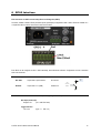
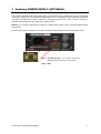
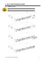
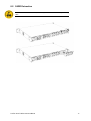
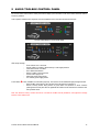
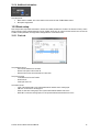
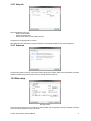
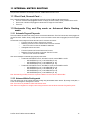
Version 1.2 FCC INFORMATION (U.S.A) This device complies with Part 15 of the FCC rules. Operation is subject to the following two conditions: 1. This device may not cause harmful interference. 2. This device must accept any interference received including interference that may cause undesired operation. NOTE: This product has been tested and found to comply with the limits for a Class B Digital device, pursuant to Part 15 of the FCC Rules. These limits are designed to provide reasonable protection against harmful interference in a residential environment. This equipment generates, uses and can radiate radio frequency energy and, if not installed and used in accordance with the instructions, may cause harmful interference to the operation of other radio communications. Compliance with FCC regulations does not guarantee that interference will not occur in all installations. If this product is found to be the source of interference, which can be determined by turning the unit “OFF” and “ON”, please try to eliminate the problems by using one of the following measures: Relocate either this product or the device that is being affected by the interference. Utilize power outlets that are on different branch (circuit breaker or fuse) circuits or install AC line filter(s). In the case of radio or TV interference, relocate/reorient the antenna. If the antenna lead-in is 300 ohm ribbon lead, change the lead-in to co-axial type cable. If these corrective measures do not produce satisfactory results, please contact the local retailer authorized to distribute this type of product IMPORTANT: When connecting this product to accessories and/or another product, use only high quality shielded cables. Cable/s supplied with this product MUST be used. AuviTran Audio ToolBox Instructions Manual 2 PRECAUTIONS WARNING DOUBLE POLE / NEUTRAL FUSING Always follow the basic precautions listed below to avoid the possibility of serious injury or even death from electrical shock, short-circuiting, damages, fire or other hazards. These precautions include, but are not limited to, the following: Do not apply excessive pressure on connectors or any other part of the board. Do not touch the metallic sharp parts (pins) of the product. This product is electrostatic sensitive; make sure you check this before touching or using it. The disconnect devices of the Audio ToolBox unit are the appliance inlet of the auxiliary power supply (option) and the appliance inlet on the rear side of the unit. These must be easily reachable. To prevent electric shock, unplug the unit before handling. The achievement of other operations not mentioned in this document is prohibited. Repairs can be performed only by a technician trained and qualified. Each connection must be Safety Extra Low Voltage kind (SELV), and must stay inside buildings. Always use a power cable with a plug according to the current standards in the country of use As Toolbox can have free slots , these slots must always have a cover to close correctly the unit (protection against fire) FINLAND: "Laite on liitettävä suojamaadoituskoskettimilla varustettuun pistorasiaan" NORWAY : "Apparatet må tilkoples jordet stikkontakt" SWEDEN : "Apparaten skall anslutas till jordat uttag" Rack Mounting This product is designed to be rack-mounted. Be sure to observe following installation rules of this kind of equipment: Do not block the vents. This device has ventilation holes on the both side to prevent the internal temperature from becoming too high. Inadequate ventilation can result in overheating, possibly causing damage to the device(s), or even fire. Elevated Operating Ambient - If installed in a closed or multi-unit rack assembly, the operating ambient temperature of the rack environment may be greater than room ambient. Therefore, consideration should be given to installing the equipment in an environment compatible with the maximum ambient temperature specified by the manufacturer. Reduced Air Flow - Installation of the equipment in a rack should be such that the amount of air flow required for safe operation of the equipment is not compromised. In some cases, to be sure to ensure sufficient airflow, leave the rear and the front of the rack open, leave sufficient space (>5cm) on each side of the rack, and leave space above rack (>1cm). Or it can be better to have appropriate fan kit in the multi-unit rack AuviTran Audio ToolBox Instructions Manual Mechanical Loading - Mounting of the equipment in the rack should be such that a hazardous condition is not achieved due to uneven mechanical loading. Circuit Overloading - Consideration should be given to the connection of the equipment to the supply circuit and the effect that overloading of the circuits might have on over current protection and supply wiring. Appropriate consideration of equipment nameplate ratings should be used when addressing this concern. Reliable Earthing - Reliable earthing of rackmounted equipment should be maintained. Particular attention should be given to supply connections other than direct connections to the branch circuit (e.g. use of power strips). 3 Warnings LIMITATION OF LIABILITY In no case and in no way, the provider of this Product (AuviTran, the distributor or reseller, or any other party acting as provider) shall be liable and sued to court for damage, either direct or indirect, caused by and to the user of the board and which would result from an improper installation or misuse of the Product. “Misuse” and “improper installation” mean installation and use not corresponding to the instructions of this manual. Please note that graphics given in this manual (drawings and schemes) are only examples and shall not be taken for a real vision of your own equipment configuration. AuviTran is constantly working on the improvement of the products. For that purpose, the products functionalities are bound to change and be upgraded without notice. Please read carefully the User’s manual as the new functionalities will be described therein. TRADEMARKS All trademarks listed in this manual are the exclusive property of their respective owners. They are respected “as is” by AuviTran. Any use of these trademarks must receive prior approval of their respective owners. For any question, please contact the trademark’s owner directly. COPYRIGHT The information in this manual is protected by copyright. Therefore, reproduction, distribution of whole or part of this manual is strictly forbidden without the prior written agreement of AuviTran. AUVITRAN WEBSITE / MORE INFORMATION Please visit our website for any question of further inquiry concerning our product range. Updates will also be posted when available. http://www.auvitran.com PACKAGE CONTAINS 1 Audio ToolBox Rack Unit 1 Power Cord AuviTran Audio ToolBox Instructions Manual 4 TABLE OF CONTENTS FCC INFORMATION (U.S.A) ............................................................................................................ 2 PRECAUTIONS................................................................................................................................ 3 LIMITATION OF LIABILITY .............................................................................................................. 4 TRADEMARKS ................................................................................................................................ 4 COPYRIGHT .................................................................................................................................... 4 AUVITRAN WEBSITE / MORE INFORMATION ............................................................................... 4 PACKAGE CONTAINS..................................................................................................................... 4 1 WELCOME!................................................................................................................................ 7 2 OVERVIEW ................................................................................................................................ 7 3 KEY FEATURES ........................................................................................................................ 7 4 AUDIO TOOLBOX RANGE AND OPTIONAL AXC-CARDS ....................................................... 8 5 TECHNICAL SPECIFICATIONS................................................................................................. 9 6 GPI/O INTERFACE ...................................................................................................................10 7 AUXILIARY POWER SUPPLY (OPTIONAL) .............................................................................11 8 SLOT AND EXTENSION CARDS ..............................................................................................12 8.1 CARD Insertion ...................................................................................................................................................... 12 8.2 CARD Extraction .................................................................................................................................................... 13 9 AUDIO TOOLBOX CONTROL PANEL......................................................................................14 10 CONFIGURATION THROUGH AVS-MONITOR ........................................................................15 10.1 Main panel .............................................................................................................................................................. 15 10.1.1 GPI/O Status ................................................................................................................................................ 15 10.1.2 Clock Status ................................................................................................................................................. 15 10.1.3 Setup access................................................................................................................................................ 15 10.1.4 Additional information ................................................................................................................................... 16 10.2 Rack setup ............................................................................................................................................................. 16 10.2.1 Clock tab ...................................................................................................................................................... 16 AuviTran Audio ToolBox Instructions Manual 5 10.2.2 10.2.3 Setup tab ..................................................................................................................................................... 17 Status tab..................................................................................................................................................... 17 10.3 Slot setup ............................................................................................................................................................... 17 11 INTERNAL MATRIX ROUTING .................................................................................................18 11.1 First-Card, Second-Card … .................................................................................................................................... 18 11.2 Automatic Plug and Play mode vs. Advanced Matrix Routing mode .................................................................... 18 11.2.1 Automatic Plug and Play mode ..................................................................................................................... 18 11.2.2 Advanced Matrix Routing mode .................................................................................................................... 18 11.3 Setting matrix mode ............................................................................................................................................... 19 11.4 Displayed status .................................................................................................................................................... 19 11.5 Matrix window ........................................................................................................................................................ 19 12 FREQUENTLY ASKED QUESTIONS........................................................................................20 13 NOTES ......................................................................................................................................21 AuviTran Audio ToolBox Instructions Manual 6 1 WELCOME! Thank you for purchasing AuviTran Audio Toolbox Rack Unit. We hope you will enjoy using it. You will find herewith the necessary instructions to use your product. Please read them carefully as misuse of this device might cause serious damage to you and your environment. 2 OVERVIEW AuviTran Audio ToolBox is a modular audio platform giving access to a large variety of professional audio networked configurations. With a three slots 1U-19” rack or a seven slots 2U-19” rack unit and several audio interface cards, you can build the configuration you need: EtherSound interface and ASIO interface (can control Audio ToolBox unit) DANTE interface (can control Audio ToolBox unit) MADI interface High quality analog input or output XLR connectors Analog inputs/outputs Euroblock connectors High quality microphone preamp inputs AES/EBU inputs/outputs GPI/GPO interface NOTE: Toolbox control is allowed if at least one card allowing control is inserted, like EtherSound Card or DANTE card. AuviTran Audio ToolBox is available in installation mode (Display in front and all connectors in the back), and can be configured as stage-box for live applications (Display, Network and Audio connectors in front, Power supply and GPIO on the back). 3 Key FEATURES AuviTran Audio ToolBox platform 19” rack (1U or 2U) chassis, providing up to seven slots for AuviTran AxC interface cards, with an audio backplane connecting all inputs / outputs (physical and network) Vast choice of audio interface cards 4 smart configurable GPIO for powerful interactions with security application. They can also be set individually as ADC Input for local / remote fader or level control. If ToolBox contains at least one control card: Remote management with AVS-Monitor software through the EtherSound or DANTE Network. Dedicated control page for monitoring and controlling all the chassis and inserted cards parameters. AuviTran Audio ToolBox Instructions Manual 7 4 Audio Toolbox Range and Optional AxC-Cards Here is the full range of available AuviTran Audio ToolBox: StageBox AVBx3-DANTE/SB Installation AVBx3-DANTE/IS AVBx3-ES100/SB AVBx3-ES100/IS AVBx7-DANTE/SB AVBx7-DANTE/IS AVBx7-ES100/SB AVBx7-ES100/IS Here is a list of available extension cards for AuviTran Audio Toolbox: AxC-DANTE AxC-ES100 AxC-MADI AxC-CN32IO AxC-AT32IO AxC-DS32IO AxC-DX8I AxC-DX8O AxC-AX4M AxC-AX4I AxC-AX4O AxC-AE8IO AxC-SWD5G AxC-GP16IO AuviTran Audio ToolBox Instructions Manual 8 5 Technical SPECIFICATIONS AVBx3: 3 slots AuviTran Audio ToolBox 1U x 19” rack Size 483 x 253x 44 mm (19” rack, 1 U height) Three slots available for control and audio inputs/outputs Main Power Supply 100-240 VAC – Maximum 50 W (depending of the configuration) Auxiliary Power Supply Available only in option Storage: Temp / Humidity -5°C to 70°C / 0% to 95% (non-condensing) Operating: Temp / Humidity 0 °C to 40°C / 5% to 90% (non-condensing) Front panel (LED display) Power Main/ Aux – Fault / Error / Ready – Networks and links Rx and Tx Activities - Events Rear panel 3 slots with backplane bus for interface cards 1x IEC power inlet for main AC power supply 2x BNC connectors for Word clock Output and Input (Zin=1KΩ or 75Ω selected by software) 1x6 poles Euroblock connector for GPIO GPI/O Connector Euroblock 6 poles with GND and Power DC Output 12V (250mA max) 4 GPI/O configurable individually as GPO or GPI o GPI = can be set as ADC level input (8 bits 0-12V) for fader control or level trigger detections o GPO = when active, force 0V (GND) on the output (support 60Vmax / 500mA max) AVBx7: 7 slots AuviTran Audio ToolBox 2U x 19” rack Size 483 x 253x 88 mm (19” rack, 2 U height) Seven slots available for control and audio inputs/outputs Main Power Supply 100-240 VAC – Maximum 110 W (depending of the configuration) Auxiliary Power Supply Available only in option Storage: Temp / Humidity -5°C to 70°C / 0% to 95% (non-condensing) Operating: Temp / Humidity 0 °C to 40°C / 5% to 90% (non-condensing) Front panel (LED display) Power Main/ Aux – Fault / Error / Ready – Networks and links Rx and Tx Activities - Events Rear panel 7 slots with backplane bus for interface cards 1x IEC power inlet for main AC power supply 2x BNC connectors for Word clock Output and Input (Zin=1KΩ or 75Ω selected by software) 1x6 poles Euroblock connector for GPIO GPI/O Connector Euroblock 6 poles with GND and Power DC Output 12V (250mA max) 4 GPI/O configurable individually as GPO or GPI o GPI = can be set as ADC level input (8 bits 0-12V) for fader control or level trigger detections o GPO = when active, force 0V (GND) on the output (support 60Vmax / 500mA max) AuviTran Audio ToolBox Instructions Manual 9 6 GPI/O Interface Each connection on GPI/O must be Safety Extra Low Voltage kind (SELV). The Audio ToolBox contains 4 GPI/O (General Purpose Input/Output) configurable as GPI or GPO. GPI/O are available on a 1x6 poles Euroblock connector close to the Power Inlet Connector. Each GPIO can be configured as GPI or GPO individually, with AVS-Monitor software. Configuration and use is described later in this document. GPO can supported 60Vdc max / 500mA max OFF State Output state = Open collector GPO OUT 60 Vdc max GPO Command ON State GPI Output state = 0 V (GND) 500mA max ON/OFF The user can select between 2 modes (Max Voltage Supported 60 Vdc) ADC Input (8 bits scale) Range 0-12V (12V = ADC Full Scale) Trigger Detection TTL Level (logic “1” = GPI > 2V) AuviTran Audio ToolBox Instructions Manual 10 7 Auxiliary POWER SUPPLY (OPTIONAL) Audio ToolBox, equipped with the auxiliary power supply, provides another source of power supply, to improve the reliability of the system. It allows you to have two distinct power supply sources, for redundancy solutions. When both power supply units (PSU) are plugged, Audio ToolBox compare them, and always choose the best. In case of failure of one PSU (or associated electrical network), Audio ToolBox will so continue to work. Warning: Do not connect a battery directly on this input. If external power supply is used, it must have protection against reverse current. The DC Aux input (option) is available on a 1x2 poles lockable Euroblock connector close to the Power Inlet Connector Input + = DC AUX input 12V (-5% (11.4V) /+12% (13.4 V)) Maximum Current 4A (depending of the configuration) Input - = GND AuviTran Audio ToolBox Instructions Manual 11 8 SLOT AND EXTENSION CARDS 8.1 CARD Insertion The cards are electrostatic sensitive; make sure you check this before touching or handling them AuviTran Audio ToolBox Instructions Manual 12 8.2 CARD Extraction The cards are electrostatic sensitive; make sure you check this before touching or handling them AuviTran Audio ToolBox Instructions Manual 13 9 AUDIO TOOLBOX CONTROL PANEL All AuviTran Audio Toolbox have a control panel used to display quick information on the device status without the need to launch any software. Control panel is available both in stage box mode and installation mode. Information provided are the same. AuviTran AVBx3 Stage box control panel display AuviTran AVBx7 Stage box control panel display LED activity meaning: - Event: reflects Core or slot event. Activity: reflects core activity, network activity or audio signal presence Fault: Default found on ToolBox Error: Malfunction detected Ready: ToolBox is ready to be used Power: Power supply is OK Main: Main power supply present Aux: Auxiliary power supply present A reset button is also available to be used with a paper clip. Two functions can be obtained through pressing this button: Reset ToolBox: press button for two seconds. Device will restart as if powered on. Revert to Factory default: while powered off, press button and powered on device. Continue pressing button until all panel LED are lighted. Both ToolBox and all slots will then reverted to their factory default values. Note: Use “Revert to Factory” function with care as it will reset all ToolBox and slot parameters, and might lead to strange behavior on the network used. AuviTran Audio ToolBox Instructions Manual 14 10 CONFIGURATION THROUGH AVS-MONITOR 10.1 Main panel Main panel is divided into 4 parts for feedback and setup functions: GPI/GPO display status, 75 status Clock source and status ToolBox name, Identify function, access to rack and/or slot setup Matrix and Power Supply status Note: AuviTran Audio ToolBox AVBx3 has no matrix function available. Internal routing follows the Automatic Plug and Play mode described later. 10.1.1 GPI/O Status This tab presents: 75 status GPI Status (ON/OFF or progress bar if set to ADC Mode display, read only) GPO Status (ON/OFF user switchable) 10.1.2 Clock Status This tab presents: Current clock source selected Current clock status o Lock/Unlock o Sync/No Sync 10.1.3 Setup access This tab presents: Rack name stored Identify function access, rack LEDs will blink during few seconds to allow quick identification Rack setup access Slot setup access AuviTran Audio ToolBox Instructions Manual 15 10.1.4 Additional information This tab presents: Matrix status if available, click on this status to have access to Audio ToolBox Matrix window Both power supply status 10.2 Rack setup Rack setup window will present several tabs to set/view all available parameters for ToolBox. The “Revert to Factory” button allows reverting to factory default parameters for both ToolBox and all slots. So use this function with care as it will reset all ToolBox and slot parameters, and might lead to strange behavior on the network used. 10.2.1 Clock tab Clock tab Clock tab allows user to: View current selected clock and status Set the 75 option for Word clock IN Select the clock used, with current status for each clock. Clock source can be: Local 48kHz clock from the ToolBox Word Clock IN Clock input from a slot Clock status can be: LOCK: This indicates that a clock synchronized with the selected source is being input. UNLOCK: A valid clock is not being input. SYNC: A valid clock is being input, and is synchronized with the selected clock source. NO SYNC: A valid clock is being input, but is not synchronized with the selected clock source. AuviTran Audio ToolBox Instructions Manual 16 10.2.2 Setup tab Setup tab Rack setup tab allows user to set: Number of GPI and GPO Display GPI as ADC meter Panel and LED dimmer for both ToolBox and slots Temperature is also displayed here in real time. Note: GPO comes first, GPI follows. Display in AVS-Monitor is automatically adapted from the current configuration. 10.2.3 Status tab Status tab The status tab presents a summary of all firmware versions present in the ToolBox. AVBx Core and GPIO/WCLK are toolbox dependant, while Slot #n presents firmware version of currently inserted card into slot. 10.3 Slot setup Slot setup window Thanks to the Slot setup window, user is able to set, when available, each slot parameters. One tab is available for each slot and is automatically adjusted to the slot card present. AuviTran Audio ToolBox Instructions Manual 17 11 INTERNAL MATRIX ROUTING This part will be dedicated to the description the Audio ToolBox Matrix and how to use it. 11.1 First-Card, Second-Card … Prior to describe available modes, cards plugged into the AuviTran Audio ToolBox will be named that way: First card: is the AxC-Card plugged into the first non empty slot of the ToolBox. Usually a network card in slot #1. Second card: is the AxC-Card plugged into the second non empty slot of the ToolBox. Third card: … 11.2 Automatic Plug and Play mode vs. Advanced Matrix Routing mode 11.2.1 Automatic Plug and Play mode This mode enables automatic audio routing sources and receivers between the “First Card” and the other cards plugged into the AuviTran Audio ToolBox. Priority routing depends on the slot number in which cards are plugged (from slower to higher slot). The automatic audio routing done follows these two rules for receivers and sources: o “First-card” sources are sent to “Second-card” receivers o Remaining “First-card” sources are then sent to “Third-card” receivers o … until no “First-Card” sources are available for distribution o Unassigned receivers are muted o o o “First-card” receivers are fed with “Second-card” sources Remaining “First-card” receivers are fed with “Third-card” sources … until no “nth-card” sources are available Here are two examples on automatic plug and play mode results: o Toolbox with AxC-DANTE in slot #1, AxC-AX4O in slot #2, and AxC-MADI in slot #3 - AxC-DANTE RCV [01..04] AxC-AX4O SRC [01..04] - AxC-DANTE RCV [05..64] AxC-MADI SRC [01..60] - AxC-DANTE SRC [01..64] AxC-MADI RCV [01..64] o Toolbox with AxC-DANTE in slot #1, AxC-AE8IO in slot #2, and AxC-MADI in slot #3 - AxC-DANTE RCV [01..04] AxC-AE8IO SRC [01..04] - AxC-DANTE RCV [05..64] AxC-MADI SRC [01..60] - AxC-DANTE SRC [01..04] AxC-AE8IO RCV [01..04] - AxC-DANTE SRC [05..64] AxC-MADI RCV [01..60] Note: Automatic Plug and Play mode is the only mode available for AuviTran Audio ToolBox AVBx3. 11.2.2 Advanced Matrix Routing mode This mode allows user to set manually the matrix routing using the dedicated matrix window. By clicking on the patch, a source can be assigned or unassigned to a receiver. Note: This mode is only available on AVBx7 with firmware 0x104. Note: When slot configuration is changed, matrix routing mode resets and sets back to Automatic Plug and Play mode. AuviTran Audio ToolBox Instructions Manual 18 11.3 Setting matrix mode Working mode can be set through Rack setup tab or through matrix window, only when available. Rack setup matrix tab 11.4 Displayed status Current status can be easily identified on the AuviTran Audio Toolbox control page. Automatic Plug and Play vs. Advanced Matrix Routing 11.5 Matrix window AVBx7 matrix window Through this window, user can view or set, when authorized, ToolBox internal matrix. It works like the NetPatch page. In addition to manually set patch between sources and receivers, two functions are available: Fully erase current matrix Change matrix mode Depending on matrix assignment, aliases available through the EtherSound NetPatch will be changed automatically to reflect sources and receivers in a user-friendly way. AuviTran Audio ToolBox Instructions Manual 19 12 FREQUENTLY ASKED QUESTIONS Is using AVS-Monitor mandatory? AVS-Monitor is used to configure the ToolBox. Once done, if no real time monitoring is necessary, you can use the AuviTran Audio ToolBox without AVS-Monitor. Why do you have to reconfigure my AuviTran Audio ToolBox at each startup? When configured with AVS-Monitor, remember to store your configuration into the device by using the “Save to flash” function. That way, your AuviTran Audio Toolbox will always start up with your configuration. How can I update the AuviTran Audio ToolBox? You can update both your ToolBox and the AxC cards through AVS-Firmware Updater in one pass, only if needed. Where is available AVS-Firmware Updater? AVS-Firmware Updater is available on the AuviTran website at: http://www.auvitran/com. AuviTran Audio ToolBox Instructions Manual 20 13 NOTES AuviTran Audio ToolBox Instructions Manual 21