1
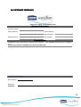
Charge Controller Manual
Approval:
Document #: 0102M01
Date: June ’07
REV : 1.2
Page 1 of 17
Registration Number 2006/005438/07
VAT Registration Number 4870231406
Tel: +27 (0)41 401 2500
Website: www.kestrelwind.co.za
Kestrel Dump
Regulator
Type 0401
Users Manual
Revision 1.0 (October 07)
For the following models of type 0401 charge regulator
Type 0401–0600-012 (e150-001-012)
Type 0401-0600-024 (e150-001-024)
Type 0401-0600-048 (e150-002-048)
600W
600W
600W
50A
35A
20A
Type 0401-0800-012 (e220-001-012)
Type 0401-0800-024 (e220-001-024)
Type 0401-0800-048 (e220-001-048)
800W
800W
800W
50A
35A
20A
Type 0401-1000-012 (e300i-001-012)
Type 0401-1000-024 (e300i-001-024)
Type 0401-1000-048 (e300i-001-048)
1000W 60A
1000W 40A
1000W 25A
Charge Regulator Manual
Approval:
Document #: 0401M01
Date: October ’07
REV : 1.1
Page 2 of 17
CONTENTS
PAGE
1
Safety Considerations
1.1
1.2
1.3
1.4
2
Components
Components Supplied
Components not Supplied
Tools Required
Unpacking
5
5
5
5
Typical Installation Example
Mounting the Dump Regulator
Electrical Wiring
Adjusting the Charging Voltage
Adjusting the Switching Delay
6
7
8
9
9
Wiring and Cable Sizing
5.1
5.2
5.3
5.4
6
4
4
4
Installation Instructions
4.1
4.2
4.3
4.4
4.5
5
Dump Regulator Description
Identification and Markings
Applications and uses
Dump Regulator Assembly
3.1
3.2
3.3
3.4
4
3
3
3
3
Dump Regulator Overview
2.1
2.2
2.3
3
Mechanical Safety
Electrical
ical Safety
Electr
Installation Hazards
Operational Safety
Wind Turbine Wiring
Battery Wiring
Lightning Protection
Wire Tables
10
10
10
10
10
11
11
Battery Considerations
6.1
6.2
6.3
6.4
Lead Acid Batteries
Sealed Gel Batteries
NiNi-Cad Batteries
Batteries
Temperature Compensation
12
12
12
2
1
12
12
12
12
7
Technical Specifications
13
13
8
Trouble shooting
14
14
9
Maintenance
15
15
10 Warranty Conditions
15
15
11 Customer Feedback
17
17
Charge Regulator Manual
Approval:
Document #: 0401M01
Date: October ’07
REV : 1.1
Page 3 of 17
Note: The dump regulator Type 0102 must be installed with a separate divert resistor.
Disclaimer
Kestrel Wind Turbines makes every effort to give accurate information in this manual and is in no
way liable for any error or omission. The user of this manual assumes full responsibility and risk.
We appeal to your common sense to read and apply the safety notes. Consult professional
engineers and take advice if you are unsure.
1 Safety Considerations
1 SAFETY FIRST
1.1
1.2
1.3
1.4
Mechanical Safety
Electrical Safety
Installation Hazards
Operational Safety
Although Kestrel’s dump regulators are designed with your safety in mind, accidents can easily
occur and there are always inherent dangers associated with any type of machine. Consult
installation professionals if you lack experience or confidence.
1.1 Mechanical Safety
Use good handling methods and take precautions to avoid physical injury during installation and
maintenance/repair procedures. Be responsible when using all tools whether manual or powered.
1.2 Electrical Safety
Read and adhere to the installation instructions for this product. Do not work on the system when the
wind turbine is running or when lightning is possible.
Disconnecting and re-connecting wires may cause a spark and the presence of explosive hydrogen
from battery charging is always a possibility. Adequate ventilation must be provided for battery
installations. The wire size used for connections must be correct for the powers supplied. The smaller
the wire diameter, the higher the wire losses and therefore the heat generated in the wire. Use
correct wire sizes throughout the installation. The amount of energy stored in a battery is
considerable and fire can result from shorts. Fit a suitable fuse or circuit breaker in the battery cable.
In general, respect the system and use common sense. Consult a qualified electrician if you are unsure.
1.3 Installation Hazards
Be sure to read and adhere to the installation instructions for this product. Always work carefully and
have an assistant wherever possible. Always re-check the work as you progress. Slack bolts, poor
workmanship and loose electrical connections must be avoided.
Operational
1.4 Op
erational Safety
Be aware that the dump regulator will become hot during certain operation modes. This is quite
normal but be aware of high temperatures within the case. System checks are best carried out in
calm weather conditions. Avoid any maintenance or inspection during windy weather.
3
Charge Regulator Manual
Approval:
Document #: 0401M01
Date: October ’07
2 DUMP REGULATOR OVERVIEW
2.1 Dump Regulator Description
REV : 1.1
Page 4 of 17
2 Dump Regulator Overview
2.1 Dump Regulator Description
2.2 Identification and Markings
2.3 Application and Uses
IMPORTANT: A suitable divert power resistor must be installed with this product
Sustainable/renewable energy sources such as wind turbines and solar panels generate
uncontrolled power that must be regulated to facilitate the correct and safe charging of storage
batteries. The Kestrel Type 0401 dump regulator uses electronic means to regulate the incoming
power to the installed battery. The product uses simple technology causing no electrical
disturbance during operation. Power from the wind turbine is delivered through the product to the
battery system. The regulator monitors the battery/system voltage and supplies power for load
consumption and battery charging. The wind turbine continually supplies the load and battery until
the battery voltage reaches the float level. The regulator then transfers the wind turbine from the
battery to a diversion resistor. As the battery voltage reduces, the regulator re-transfers the wind
turbine from the diversion resistor back on to the battery. The cycle then repeats.
Any excess energy is converted to heat in the diversion resistor. The regulator also maintains an
optimum load on the turbine at all times to prevent the turbine speed becoming excessive. The unit
is highly efficient and allows the wind turbine to bulk charge very low or flat batteries. Since the
controller is external to the generator, it can be sited close to the batteries. This gives accurate
battery voltage measurement and tight regulation.
2.2 Identification and Markings
On the cover of the charge controller is a product rating plate and serial number, if the charge
controller does not carry this stamp it does not carry a Kestrel warranty and may not be authentic.
2.3 Applications
Applications and Uses
The Kestrel Charge Controller Type 0102 is primarily intended for use with Kestrel wind turbines
that are installed for battery charging. Each application may require specific additional electrical
equipment. Consult the manuals supplied with this equipment.
4
Charge Regulator Manual
Approval:
Document #: 0401M01
Date: October ’07
REV : 1.1
Page 5 of 17
3 Dump Regulator Assembly
3 DUMP REGULATOR ASSEMBLY
3.1
3.2
3.3
3.4
Components Supplied
Components Not Supplied
Tools Required
Unpacking
3.1 Components Supplied
The following components are supplied:
Dump Regulator assembly
User Manual
3.2 Components Not Supplied
The following components are necessary to complete an installation:
Electrical crimp terminals
Wall fixing screws
20mm cable glands
Suitable fixing screws or bolts
3.3
3.3 Tools Required
The following hand tools are required for the charge controller installation:
Small size electrical screwdriver
Medium size electrical screwdriver
Wire strippers for electrical connections
Electrical crimping pliers
Tape measure for positioning
3.4
3.4 Unpacking
Open the packaging container and check for any transit damage. The parts contained are listed
in section 3.1 and on the included packing slip. Lay out and identify the parts.
5
Charge Regulator Manual
Approval:
Document #: 0401M01
Date: October ’07
REV : 1.1
Page 6 of 17
4 Installation Instructions
4 INSTALLATION INSTRUCTIONS
4.1 Typical Installation Example
4.1
4.2
4.3
4.4
Typical Installation Example
Mounting the Regulator
Electrical Wiring
Adjusting the Charging Voltage
A typical battery charging installation is shown below. The system comprises a Kestrel wind
turbine, dump regulator or charge controller, diversion resistor, battery and an inverter. The
inverter is additional and converts the battery dc power into standard ac power such that common
mains powered appliances can be supplied.
NOTE: The load circuit breaker and inverter are additional equipment and not supplied with
the dump regulator. The diversion resistor is supplied as a separate item. The Type 0401
dump controller must have a diversion resistor fitted.
6
Charge Regulator Manual
Approval:
Document #: 0401M01
Date: October ’07
REV : 1.1
Page 7 of 17
4.2 Mounting the Regulator
The Kestrel dump regulator Type 0401 is only suitable for indoor installation. The unit must be
vertically mounted using the four external fixing holes provided. Use secure fastening with suitable
wall plugs or bolts. Allow a minimum of 100mm (4”) space all around the unit for cooling. It is
normal for the regulator to become quite hot at times as it dissipates unwanted energy.
Do not place any objects on the top of the enclosure. The unit relies on the free passage of air
through the heat sink for cooling.
7
Charge Regulator Manual
Approval:
Document #: 0401M01
Date: October ’07
REV : 1.1
Page 8 of 17
4.3
4.3 Electrical Wiring
Observe the Polarity at all times. Only connect +VE RED cables to +VE RED terminals and -VE
BLACK cables to -VE BLACK terminals. Otherwise, equipment damage may result and any
warranty will be invalidated.
PLEASE FOLLOW THE INSTRUCTIONS BELOW !
CONSULT SECTION 5 FOR WIRE SIZE RECOMMENDATIONS
The dump regulator is provided with two pairs of +VE and -VE
clearly marked terminals for "TURBINE" and "BATTERY" and one
pair of DIVERT RESISTOR terminals clearly marked R1A and R1B
at the bottom of the regulator. The TURBINE BRAKE switch is
designated “S1” and the BATTERY CIRCUIT BREAKER is designated
“Q1”. If these items are not fitted within the controller, they should
be installed externally to suit local electrical requirements. The
turbine brake switch stops the turbine by creating an electrical
short on the turbine input. When operated, this prevents high
turbine open circuit voltages being developed.
The wind turbine should not be rotating during this installation. If turbine access is not
possible, short the two turbine power wires together. Observe the Polarity at all times. Only
connect +VE RED cables to +VE RED terminals and -VE BLACK cables to -VE BLACK terminals.
a) Arrange the wires from the turbine and the battery ready for connection.
b) Check that the turbine wires are shorted. Check that the battery wires are disconnected from
the battery or that any additional battery fuse or circuit breaker is disabled.
c) Check that the regulator BATTERY CIRCUIT BREAKER (Q1) is switched OFF and that the
TURBINE BRAKE SWITCH (S1) is switched ON.
d) Connect the wiring between the regulator terminals R1A and R1B to the divert resistor
enclosure terminals R1A and R1B respectively.
e) Connect the battery wires to the regulator battery terminals +VE and –VE observing polarity.
f) Connect an electrical earth wire to the marked earth screw terminal provided.
g) Separate the turbine wires and connect the turbine negative wire to the controller turbine
negative terminal. You may have to improvise by maintaining a short on the turbine wires as
this connection is made.
h) Finally connect the turbine positive wire to the regulator turbine positive terminal.
i)
Switch the battery circuit breaker ON. (There is no reaction)
j)
Switch the turbine switch OFF. (If enough wind is present, the green LED on the control board
will illuminate showing the turbine to be active)
The instructions are reversed for de-commissioning. First disconnect or switch the battery off.
Then remove the turbine wires and then the battery connections. A disconnected turbine
should always be shorted.
8
Charge Regulator Manual
Approval:
Document #: 0401M01
Date: October ’07
REV : 1.1
Page 9 of 17
4.4
4.4 Adjusting the Charging Voltage
Always switch the turbine brake on (S
S1 ON) and the battery circuit breaker off (Q
Q1 OF F )
before adjusting the charging voltage jumper
The Kestrel dump regulator Type 0401 is suitable for all lead acid batteries whether vented,
semi-sealed or sealed and the charging voltage may be adjusted. When the cover is removed, the
jumper is visible in the middle of the control board. The charging voltage may be adjusted to the
following table.
There are five positions for the jumper. The value is the charging cell voltage. The derived
battery charging voltages are given in the tables below. Consult your battery supplier for the
correct charging voltage.
Charging voltages for 12V system
-
-
2,366
2,350
2,333
2,315
2,300
14,2V
14,1V
14,0V
13,9V
13,8V
Charging voltages for 24V system
-
-
2,366
2,350
2,333
2,315
2,300
28,4V
28,2V
28,0V
27,8V
27,6V
Charging voltages for 48V system
-
-
2,366
2,350
2,333
2,315
2,300
56,8V
56,4V
56,0V
55,6V
55,2V
4.5
4.5 Adjusting the Switching Delay
The regulator diverts all the turbine power when the battery is charged; it is possible for the
battery voltage to drop quite quickly under certain load conditions. This can cause the regulator
to cycle on and off. This behaviour is prevented by a digital timer. Select the minimum time to end
a power diversion by re-positioning the timer jumper on the top of the PCB board. Three times
are available, 30s, 30m and 1hr.
9
Charge Regulator Manual
Approval:
Document #: 0401M01
Date: October ’07
5 WIRING
WIRING AND CABLE SIZING
SIZING
REV : 1.1
Page 10 of 17
5 Wiring and Cable Sizing
5.1 Wind Turbine Wiring
5.1
5.2
5.3
5.3
Wind Turbine Wiring
Battery Wiring
Lightning Protection
Wire Tables
Kestrel wind turbines produce dc power and output on two double insulated output wires (tails).
The RED wire is POSITIVE and the BLACK wire is NEGATIVE
Observe the Polarity at all times. Only connect +VE RED cables to +VE RED terminals and -VE
BLACK cables to -VE BLACK terminals. Otherwise, equipment damage may result and any
warranty will be invalidated.
The following suggestions are made as a guideline. If you are in doubt, consult an electrician.
The output wires must be extended as required for the installation. Choose the wire size that is
suggested for the size of turbine, electrical current and the distance from the turbine to the charge
controller. Good wire connections are absolutely essential to avoid poor power delivery and high
temperatures at the connection.
All electrical systems lose energy because cables have a resistance. The mounting structure must be
directly earthed for lightning. The power cable is usually brought down the inside of the mounting
structure to give some protection. Supply cables should never be spanned or suspended from the
turbine structure and should be buried at least one half metre deep in a suitable plastic or steel
conduit.
5.2 Battery Wiring
The battery wiring is usually chosen to be the same size as the turbine power wiring but a smaller
wire diameter can be used because the distance is usually much shorter between the charge
controller and the battery.
5.3 Lightning protection
Proper grounding is essential to protect the system from induced voltages and static. The
installation must comply with local requirements for electrical installations. Ensure that the
generator is electrically connected to the mounting structure and that the structure is earthed. This
is usually done by burying a 2 to 3m (6’ – 10’) length of water pipe (steel or copper) horizontally,
800mm (2,5’) below the ground surface. A good connection is made between the middle of the
pipe and the structure. An improved method is to bury a cross of pipe, which requires an "X"
shape to be excavated. The connection is made in the centre of the cross.
The negative battery connection should also be grounded using a ground point close to the
battery. The wire size for grounding should be the same size as the power cables. Commercial
lightning arrestors are available at electrical stores and can be fitted at the bottom of the
structure or pole or at the regulator input.
10
Charge Regulator Manual
Approval:
Document #: 0401M01
Date: October ’07
REV : 1.1
Page 11 of 17
5.4 Wire Tables
The copper wire sizes given in the tables are calculated for 3% power loss in wire resistance. This
is usually acceptable in low voltage installations. A larger wire size will increase the delivered
power but usually a compromise is reached as larger cables cost more. It is recommended that the
wire sizes given be taken as a minimum value.
Measure the distance from the top of your structure (i.e. the e150) to the regulator. Select the wire
size for that distance from the table. The double run of +ve and -ve is already accounted for.
The power cable should be run down the inside of the pole or structure and then buried in a
suitable underground conduit at least 500mm below the ground surface.
Wire lengths account for a double cable run (both +ve and –ve together) being given in metric
metres (m) and imperial feet (‘). Wire cross sectional area is given in metric square millimetres
(sq mm) and American Wire Gauge AWG.
Wire Size for 12V (60A maximum current)
10m (33’)
35sq mm (2)
20m (66’)
45sq mm (1)
30m (96’)
85sq mm (000)
Wire Size for 24V (32A maximum current)
10m (33’)
16sq mm (5)
20m (66’)
35sq mm (2)
30m (96’)
50sq mm (0)
40m (130’)
70 sq mm (00)
50m (165’)
95 sq mm(0000)
40m (130’)
50m (165’)
Wire Size for 48V (19A maximum current)
10m (33’)
20m (66’)
30m (96’)
10sq mm (7)
20sq mm (4)
35sq mm (2)
35sq mm (1)
50sq mm (0)
80m(260’)
70sq mm (00)
100m (330’)
100sqmm(0000)
11
Charge Regulator Manual
Approval:
Document #: 0401M01
Date: October ’07
REV : 1.1
Page 12 of 17
6 Battery Considerations
6 BATTERY CONSIDERATIONS
CONSIDERATIONS
6.1
6.2
6.3
6.4
Lead Acid Batteries
Sealed Gel Batteries
Ni-Cad Batteries
Temperature Compensation
Batteries are available in many shapes, sizes and chemistry. Battery dealers will be pleased to
assist. The most common ones are reviewed below. In general, only "Deep cycle" batteries and
cells should be used and automotive or vehicle batteries will have a short life as they are not
designed for cyclic charging and discharging. A cell is a single unit of 2V and a battery consists of
a number of cells joined in series. The usual installation consists of 12V batteries arranged in series
or parallel, or both. Batteries should not be exposed to temperature extremes and good
ventilation is required as batteries can emit hydrogen while being charged.
The stored energy in a battery is given in Ampere Hours (Ah) or Watt hours (Wh). The capacity is
often based on a 10 hour discharge rate. A 100Ah battery will therefore supply a current of 5A
for 20hrs or 10A for 10hrs or 20A of current for 5hrs. It will not however supply 100A of current
for 1hr. There is much literature available on this subject. The installed battery capacity in Ah is
calculated from the autonomy in the system. The autonomy is the time that the battery must supply
power to the load with no wind energy being input. The question to be answered is therefore,
“How long must the battery run the load when there is no wind?”. Other considerations relate to
the charging current available from the wind turbine and the time allowed for the batteries to
recover to a state of full charge. Consult your dealer or battery supplier.
6.1 Lead Acid Batter
Batteries.
ies.
These are the most popular choice of battery type and can be vented/flooded (water may be
added), or semi-sealed or low maintenance (water cannot be added). Charging voltage is
typically 13.8-14.0 / 27.6-28.0Vdc for these batteries.
6.2 Sealed Gel B
Batteries
atteries
Sealed gel batteries are more expensive but offer clean and safer operation as no acid can be
spilled. Since they are sealed, they must never be boosted and the charging voltage is important.
Charging voltage is typically 14.0 / 28.0Vdc. Consult your battery supplier.
6.3 Ni
Ni--Cad Batteries
This type of battery is traditionally used where large currents must be delivered and where deep
cycling is required. They are however relatively expensive. Consult your battery supplier for
details.
6.4 Tempera
Temperature
ture Compensation
Much has been documented on this subject and there are certain merits. Generally, lower and
higher ambient temperatures allow higher and lower charging voltages respectively. K600
regulators do not have this facility. Batteries should be sited in a cool area and temperature
compensation is only useful in extreme temperature variations.
12
Charge Regulator Manual
Approval:
Document #: 0401M01
Date: October ’07
REV : 1.1
Page 13 of 17
7 TECHNICAL SPECIFICATIONS
General: Switch diversion dump regulator to telecommunication specification with 600, 800
and 1000W capability for the charging of storage batteries. Supplied to order for system
voltages of 12, 24, 48Vdc.
Controller Model
Rated Power
Maximum Current
Type 0401–0600-012 (e150-002-012)
Type 0401-0600-024 (e150-002-024)
Type 0401-0600-048 (e150-002-048)
600W
600W
600W
50A
25A
15A
Type 0401-0800-012 (e220-002-012)
Type 0401-0800-024 (e220-002-024)
Type 0401-0800-048 (e220-002-048)
800W
800W
800W
60A
30A
20A
Type 0401-1000-012 (e300i-002-012)
Type 0401-1000-024 (e300i-002-024)
Type 0401-1000-048 (e300i-002-048)
1000W
1000W
1000W
60A
40A
25A
Input voltage and variation
12Vdc (0-40V), 24Vdc (0 – 60V) 48Vdc (0 – 100V)
Efficiency
12V - 97%, 24V and 48V– 99% at full load
Input frequency
N/A dc input
Input Protection
Polarity reversal
Input power factor
Output Voltage
N/A dc input
Adjustable for 2,30V, 2,316V, 2,333V, 2,35V, 2,366V VPC
Output voltage ripple
Output voltage regulation
User control
User controls external
LED Indication
Cooling
<1%rms
<1%
PCB Jumper for output voltage setting
None
Internal running LED (Green)
Natural Convection
Maximum Ambient
40deg C
IP Rating
IP35
Cabinet Dimensions (wall mounting)
Certification
230Wx230Hx130D
Complies with EMC requirements CIS22 Class B
13
Charge Regulator Manual
Approval:
Document #: 0401M01
Date: October ’07
REV : 1.1
Page 14 of 17
8 TROUBLE SHOOTING
THE KESTREL TYPE 0401 DUMP REGULATOR MAY BE SERIOUSLY DAMAGED FROM
POLARITY REVERSAL. (wrong connection of +ve and –ve wiring). THE CONTROLLER MUST BE
WIRED IN CONJUNCTION WITH A SUITABLE DIVERSION POWER RESISTOR. CONTROLLER
FAILURE AND/OR OVERCHARGING OF THE BATTERY CAN OCCUR WITH THE WRONG
VALUE OF DIVERSION RESISTOR.
IF FOR ANY REASON THE WIND TURBINE IS DISCONNECTED, SHORT THE GENERATOR
OUTPUT WIRES. THIS WILL LOAD THE GENERATOR AND MINIMISE ROTATION.
WHEN THE CONTROLLER IS CONNECTED TO A SOLAR PANEL SYSTEM, THE OUTPUT
VOLTAGE JUMPER MAY HAVE TO BE ADJUSTED TO BALANCE THE CHARGING FROM THE
TURBINE WITH THE SOLAR PANELS.
Q
There is wind but the internal green LED does not come on.
A
The turbine stop switch is ON. The turbine has not reached the cut in voltage, a higher wind
is required. There is an electrical short elsewhere in the system.
Q
The Battery circuit breaker trips.
A
Battery cables are reversed. Controller diodes are faulty.
Q
The regulator is always working at a high temperature.
A
The unit is diverting energy. Fit additional batteries and increase the load.
Q
Will I damage the regulator if I disconnect the battery.
A
No, the controller will continue to control with no battery connected. It will however become
quite hot as it has to divert all the energy from the wind turbine. It is best to operate the
turbine stop switch rather than have the controller working so hard for no reason.
14
Charge Regulator Manual
Approval:
Document #: 0401M01
Date: October ’07
REV : 1.1
Page 15 of 17
9 MAINTENANCE
The Kestrel Type 0401 dump regulator is designed for continuous operation on 100% duty cycle
and requires no regular part replacement. Keep the unit clean and ensure that no foreign objects
reduce the airflow through the rear aluminium heat sink. Clean the case only with a soft damp
cloth. Do not use any form of solvent.
10 WARRANTY CONDITIONS
Kestrel’s wind turbines and dump regulators are manufactured to the highest standards, in
accordance with Kestrel Wind Turbines’ standard and quality specifications, and warrants that the
dump regulator is in good working order upon delivery and for a period of 24 months. Warranty
terms and conditions are outlined below.
1.
Eveready warrants that Regulators will, on delivery, be free of defects in design, material and
workmanship and will be fit for their intended purpose for a period of two years calculated from the
date of installation, subject to proper installation, maintenance and use in accordance with the User
Manual.
2.
This warranty is further subject to the Customer returning the defective Regulators at its cost to the
premises of Eveready within the warranty period and furnishing full details in writing of the alleged
defect.
3.
Eveready's obligations under this warranty shall be limited to the repair or replacement of defective
Regulators at its cost or to a refund to the Customer of the original cost thereof, as Eveready may
determine in its discretion. Eveready shall not be responsible for any damages suffered by the
Customer pursuant to any defects covered by this warranty.
4.
This warranty shall not apply to any damage to Regulators caused by winds exceeding 160
kilometres per hour or any other factors beyond the control of Eveready.
5.
The Customer may purchase an extended warranty from Eveready in respect of Regulators, subject
to Eveready's standard conditions.
15
Charge Regulator Manual
Approval:
Document #: 0401M01
Date: October ’07
REV : 1.1
Page 16 of 17
CONTACT KESTREL WIND TURBINES
Kestrel Wind Turbines
P.O. Box 3191
Eveready Diversified Products (Pty) Ltd
North End
Eveready Road
Port Elizabeth
Struandale
6056
North End
Eastern Cape
Port Elizabeth
Republic of South Africa
South Africa
Tel: +27 (0)41 401 2500
Email: [email protected]
Registration Number 2006/005438/07
VAT Registration Number 4870231406
Web: www.kestrelwind.co.za
16
Charge Regulator Manual
Approval:
Document #: 0401M01
Date: October ’07
REV : 1.1
Page 17 of 17
10 CUSTOMER FEEDBACK
Customer enquiry and feedback sheet
Customer Information
Information
Customer Name:
Postal Address:
Serial Number:
Phone Number:
E-Mail Address:
Fax Number:
Enquiry Details
Complete the form and submit to Kestrel Wind Turbines. Your feedback and queries are valuable
to us.
Indicate your enquiry or feedback in the space provided below
For OFFICIAL Use Only
Date Replied:
Signature:
Comments:
17