1
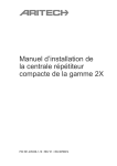
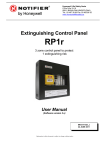
FEC403EN User Manual
P/N 10-4101-505-2FC1-01 • ISS 22JAN15
Copyright
Trademarks and
patents
Manufacturer
© 2015 UTC Fire & Security. All rights reserved.
The FEC403EN name and logo are trademarks of
UTC Fire & Security.
UTC CCS Manufacturing Polska Sp. Z o.o.
Ul. Kolejowa 24. 39-100 Ropczyce, Poland
Authorized EU manufacturing representative:
UTC Fire & Security B.V.
Kelvinstraat 7, 6003 DH Weert, Netherlands
Version
This document applies to FEC403EN version 3.0
Certification
2012/19/EU (WEEE directive): Products marked with this symbol
cannot be disposed of as unsorted municipal waste in the European
Union. For proper recycling, return this product to your local supplier
upon the purchase of equivalent new equipment, or dispose of it at
designated collection points. For more information see:
www.recyclethis.info.
2006/66/EC (battery directive): This product contains a battery that
cannot be disposed of as unsorted municipal waste in the European
Union. See the product documentation for specific battery
information. The battery is marked with this symbol, which may
include lettering to indicate cadmium (Cd), lead (Pb), or mercury
(Hg). For proper recycling, return the battery to your supplier or to a
designated collection point. For more information see:
www.recyclethis.info.
Contact information
For contact information, see www. utcfssecurityproducts.eu.
Content
Important information ii
Limitation of liability ii
Agency compliance ii
European regulations for construction products iii
User guide 1
Keyboard layout 1
Access levels 2
Starting up the panel 2
LED indicators, buttons and acoustic indicators 2
Operating modes 10
In the event of fire or fault 14
General 14
Extinguishing 14
Troubleshooting, maintenance, support 15
Troubleshooting 15
Maintenance 17
Contacting technical support 17
FEC403EN User Manual
i
Important information
Limitation of liability
Installation in accordance with this manual, applicable codes, and the instructions
of the authority having jurisdiction is mandatory. UTC Fire & Security shall not
under any circumstances be liable for any incidental or consequential damages
arising from loss of property or other damages or losses owing to the failure of
UTC Fire & Security products beyond the cost of repair or replacement of any
defective products. UTC Fire & Security reserves the right to make product
improvements and change product specifications at any time.
While every precaution has been taken during the preparation of this manual to
ensure the accuracy of its contents, UTC Fire & Security assumes no
responsibility for errors or omissions.
Agency compliance
This product has been designed according to the following standards:
•
EN54-2, EN54-4
•
EN60950-1
•
EN12094-1
•
ANPI TN121
•
EMC Immunity EN50130-4
•
EMC Emissions EN61000-6-3, EN61000-3-2, EN61000-3-3
The EN12094-1 standard includes basic and optional requirements. The optional
requirements this product meets are:
Table 1: EN12094-1 optional requirements
Clause
Description
4.17
Extinguishing agent release delay
4.18
Signal representing the flow of agent
4.19
Monitoring of the status of components
4.20
Emergency hold device (mode A or B)
4.23
Manual only mode
4.24
Triggering signals to equipment within the system
4.26
Triggering signals to equipment outside the system
4.27
Emergency abort device
4.30
Activation of alarm device with different signals
ii
FEC403EN User Manual
European regulations for construction products
This section includes both regulatory information and a summary on the declared
performance according to the Construction Products Regulation 305/2011. For
detailed information refer to the product Declaration of Performance (DoP).
Table 2:
Certification
Certification body
1134
Manufacturer
UTC CCS Manufacturing Polska Sp. Z o.o.
Ul. Kolejowa 24. 39-100 Ropczyce, Poland
Authorized EU manufacturing representative:
UTC Fire & Security B.V., Kelvinstraat 7,6003 DH Weert,
The Netherlands
Year of first CE marking
09
Declaration of Performance
number
360-3319-0199
EN 54
EN12094-1, EN54-2,
EN54-4, Environmental Class A
Product identification
See model number on product identification label
Intended use
See DoP point 3
Essential characteristics
See DoP point 9
FEC403EN User Manual
iii
iv
FEC403EN User Manual
User guide
Keyboard layout
Figure 1: Keyboard layout
1.
Fire LEDs (general / zone)
2.
Fault LEDs (general / zone)
3.
Maintenance LED
19. Gas flow LEDs (Active / Fault) C. Test button
4.
Fault return LED
20. Door monitor LEDs (Active /
5.
Supply fault LED
6.
System fault LED
21. FBRIG delay LED
F. Sounder 1 stop button
7.
Out of service LED
22. FBRIG start LEDs (Active /
G. FBRIG start button
8.
Supply on LED
9.
Disable LED (general)
10. Test LED
11. Manual mode LED
12. Start MCP fault LED
18. Gas pressure LEDs (Active /
Fault)
Fault)
Fault)
23. Sounder 1 stop LEDs (Active
/ Fault)
24. Sounder 2 stop LEDs (Active
B. Disable extinguishing button
D. Disable button (general)
E. Sounder 2 stop button
H. FBRIG delay button
J. Silence Buzzer button
K. Reset button
L. Access key (level 1 / level 2)
/ Fault)
13. Released LED
25. Silence buzzer LED
14. Extinguishing activated LED
26. Reset LED
15. Extinguishing fault/disable
27. Auxiliary disabled LED
LED
A. Zone buttons (Z1, Z2, Z3)
28. Warning sign fault LED
16. Hold MCP LEDs (Active/Fault) 29. Evacuate sign fault LED
17. Abort MCP LEDs
30. Released sign fault LED
(Active/Fault)
FEC403EN User Manual
1
Access levels
In accordance with EN54 guidelines the FEC403EN uses a restricted access
protocol for increased security. Access levels are controlled via the access key
(see Figure 1).
Access levels are as follows:
Access level 1
When the key is turned to the locked position access level 1 is active.
This access level allows activation of the Silence Buzzer button and cancellation
of any programmed fire brigade delay via the FBRIG delay button. No other
system controls are available in access level 1.
Access level 2
When the key is turned to the unlocked position access level 2 is active.
This access level allows full control of the extinguishing control panel and
features and is reserved for the user responsible for operating the system.
Starting up the panel
The panel can start up in one of two ways: normal startup and a special startup
sequence used after an internal fault has been detected by the panel (in
accordance with EN12094-1).
The EN12094-1 fault startup is indicated by the following:
•
•
•
General fault LED (flashing)
System fault LED (slow flash)
Reset LED (flashing)
When the panel is in this condition pushing the reset button will restart the panel.
If the panel continues to detect a fault the startup sequence will not be completed
and sytem fault LED will be activated (constant).
LED indicators, buttons and acoustic indicators
See Figure 1 for the location of all items. A reference in square brackets - for
example [9] - refers to the item listing in this figure.
LED indicators
1. Fire (general)
Two red LEDs indicate an alarm in the system. Flashing LEDs indicate that a
detector has activated the alarm. Constant LEDs indicate that a manual call point
has activated the alarm.
2
FEC403EN User Manual
1. Fire (zone)
The zone in alarm is indicated by a red LED above the zone button (zone 1, 2 or
3).
2. Fault (general / zone)
A constant yellow LED indicates that the zone is either disabled or in test mode.
A flashing yellow LED indicates a fault. The zone in fault is indicated by a yellow
LED above the corresponding zone button (zone 1, 2 or 3).
Test or disabled status can be determined by the general Disable [9] or Test [10]
LEDs described later in this section.
3. Maintenance
This feature is for installations using Clean-Me enabled detectors only.
A constant yellow LED indicates that detector maintenance is required. The
detector zone is displayed when the Silence Buzzer button [J] is pressed for
more than three seconds.
4. Fault return
A slow flashing yellow LED indicates a fault on the input. A fast flashing yellow
LED indicates that the input has been activated.
5. Supply fault
A constant yellow LED indicates a battery or mains power supply fault. As a
single LED is used to indicate both types of fault ensure that both mains and
battery fuses are checked when a supply fault is indicated.
6. System fault
A constant yellow LED indicates that a software fault in the control panel has
been detected.
7. Out of service
A constant yellow LED indicates that the control panel has lost power and battery
voltage is below the minimum required value (22 VDC).
8. Supply on
A constant green LED indicates that the control panel is powered up correctly by
either the mains power supply or battery.
9. Disable (general)
A constant yellow LED indicates that one or more features of the control panel
have been disabled. The corresponding LED for the disabled feature will also be
activated.
10. Test (general)
A constant yellow LED indicates that one or more features of the control panel
are in test mode. The corresponding LED for the feature being tested will also be
activated.
FEC403EN User Manual
3
11. Manual mode
A constant yellow LED indicates that the control panel is in manual mode.
Manual mode may only be activated using an external key-operated manual call
point. In manual mode extinguishing can only be activated by a start manual call
point - the extinguishing process will not start automatically if a fire alarm is
detected in zones 1 and 2.
12. Start MCP fault
A constant yellow LED indicates that the start extinguishing manual call point has
been disabled. A slow flashing yellow LED indicates that there is a fault with the
start extinguishing manual call point line supervision (open or short-circuit). A fast
flashing yellow LED indicates that the start extinguishing manual call point has
been activated.
13. Released
A constant red LED indicates that the extinguishing agent has been released. A
flashing red LED indicates that the actuators have been activated and the panel
is waiting for confirmation (if the gas flow switch is configured).
14. Extinguishing activated
A flashing red LED indicates a pre-alarm (zone 1 or zone 2 is in alarm). A
constant red LED indicates an activated state (zone 1 and zone 2 are in alarm or
a start manual call point has been activated) and that any configured
extinguishing delay is running.
Note: A delay of between 5 and 60 seconds may be programmed during
installation for the extinguishing agent release
15. Extinguishing fault / disable
A constant yellow LED indicates that the automatic extinguishing process has
been disabled via the control panel. A flashing yellow LED indicates a fault in the
extinguishing actuator circuitry.
16. Hold MCP (Active / Fault)
A fast flashing yellow LED (ACT) indicates that the extinguishing process has
been delayed by a hold extinguishing manual call point.
A flashing yellow LED (FLT) indicates a fault.
17. Abort MCP (Active / Fault)
A fast flashing yellow LED (ACT) indicates that the extinguishing process has
been cancelled by an abort extinguishing manual call point.
A flashing yellow LED (FLT) indicates a fault.
18. Gas pressure (Active / Fault)
A fast flashing yellow LED (ACT) indicates that the gas pressure input has been
activated (the pressure in the gas bottles is low). For some installations this input
is connected to the weight switch.
4
FEC403EN User Manual
A flashing yellow LED (FLT) indicates a fault in the line supervision (open or
short-circuit). A constant yellow LED (FLT) indicates that the feature has been
disabled or is in test mode (check the general Disable [9] and general Test LEDs
[10] for verification).
19. Gas flow (Active / Fault)
A fast flashing yellow LED (ACT) indicates that the gas flow input has been
activated (the gas is flowing from the bottles).
A flashing yellow LED (FLT) indicates a fault in the line supervision (open or
short-circuit). A constant yellow LED (FLT) indicates that the feature has been
disabled or is in test mode (check the general Disable [9] and general Test LEDs
[10] for verification).
20. Door monitor (Active / Fault)
A fast flashing yellow LED (ACT) indicates that the door monitor input has been
activated. In standby (with the system in automatic mode) the input is activated if
the monitored door is open, or (if the system is in manual mode) if the door is
closed. In activated or released state the input is activated if the door is open.
A flashing yellow LED (FLT) indicates a fault in the line supervision (open or
short-circuit).
21. FBRIG delay
A constant yellow LED indicates that any programmed fire brigade delay has
been activated.
Note: A delay of between 1 and 10 minutes may be programmed for this feature
during installation.
22. FBRIG start (Active / Fault)
A constant red LED (ACT) indicates that the fire brigade output has been
activated (the call fire brigade procedure has started).
A flashing yellow LED (FLT) indicates a fault in the line supervision (open or
short-circuit). A constant yellow LED (FLT) indicates that the feature has been
disabled or is in test mode (check the general Disable [9] and general Test LEDs
[10] for verification).
23. Sounder 1 stop (Active / Fault)
A constant red LED (ACT) indicates that the first stage sounder (pre-alarm) has
been activated (zone 1 or zone 2 is in alarm).
A flashing yellow LED (FLT) indicates a fault in the line supervision (open or
short-circuit). A constant yellow LED (FLT) indicates that the feature has been
disabled or is in test mode (check the general Disable [9] and general Test LEDs
[10] for verification).
FEC403EN User Manual
5
24. Sounder 2 stop (Active / Fault)
A constant red LED (ACT) indicates that the second stage sounder (alarm) has
been activated (zone 1 and zone 2 are in alarm or a start manual call point has
been activated).
A flashing yellow LED (FLT) indicates a fault in the line supervision (open or
short-circuit). A constant yellow LED (FLT) indicates that the feature has been
disabled or is in test mode (check the general Disable [9] and general Test LEDs
[10] for verification).
25. Silence buzzer
A constant yellow LED indicates that the internal buzzer has been silenced.
26. Reset
A constant yellow LED indicates that the reset button is blocked by an activation
delay (described later).
27. Auxiliary disabled
A constant yellow LED indicates that the auxiliary output has been disabled.
28. Warning sign fault
A flashing yellow LED indicates that there is a fault with the illuminated warning
sign line supervision (open or short-circuit). A constant LED indicates that the
sign is disabled or in test mode (check the general Disable [9] and general Test
LEDs [10] for verification).
29. Evacuate sign fault
A flashing yellow LED indicates that there is a fault with the illuminated evacuate
sign line supervision (open or short-circuit). A constant LED indicates that the
sign is disabled or in test mode (check the general Disable [9] and general Test
LEDs [10] for verification).
30. Released sign fault
A flashing yellow LED indicates that there is a fault with the illuminated
extinguishing released sign line supervision (open or short-circuit). A constant
LED indicates that the sign is disabled or in test mode (check the general Disable
[9] and general Test LEDs [10] for verification).
Buttons
A. Zones (Z1, Z2, Z3)
Enables / disables a zone. A disabled zone is indicated by a constant yellow
LED.
B. Disable extinguishing
Used with the disable sequence described in Disable (general). Disables the
extinguishing area and prevents activation of the extinguishing process.
Caution: If extinguishing has been activated via a manual call point or if the
panel is in activated mode the extinguishing process cannot be disabled.
6
FEC403EN User Manual
A fault on the hold extinguishing manual call point or the abort extinguishing
manual call point will automatically disable the actuator.
If the actuator is disabled automatically due to a manual call point fault it will be
enabled after resetting the control panel (assuming the fault has been fixed). If
the actuator has been disabled manually the disabled state is not changed by
resetting the control panel.
C. Test
This feature can only be used when the control panel is in standby mode.
Tests a control panel controlled feature or component. Limited testing is available
in access level 1.
What can be tested with level 1 access:
•
•
All control panel LEDS
Internal buzzer
Access level 1 test procedure:
1. Press the Test button and keep it pressed.
2. To terminate the test depress the Test button.
While the test is active (the Test button is pressed) all control panel LEDS will be
lit and the internal buzzer will sound continuously.
What can be tested with level 2 access:
•
•
•
•
•
•
•
•
•
•
Zones (zone 1, 2 or 3)
Start extinguishing manual call point
Hold extinguishing manual call point
Abort extinguishing manual call point
Pressure switch
Gas flow switch
First stage sounder (pre-alarm)
Second stage sounder (alarm)
Fire brigade
Illuminated warning signs
Access level 2 test procedure:
To test zone 1, zone 2, zone 3, extinguishing, fire brigade and stage 1 or stage 2
sounders:
1. Press the Test button (marked "C" in Figure 1) and the button of the function /
feature to be tested at the same time (for example press Test and the Z1
button together to test zone 1).
2. Repeat this process to terminate the test.
For the remaining level 2 test options:
1. Press the Test button (marked "C" in Figure 1) for 3 seconds and then select
the feature / component to be tested by pressing the Test button repeatedly
until the LED for the desired feature / component flashes quickly.
FEC403EN User Manual
7
2. To activate the test for the selected feature / component turn the keyswitch to
level 1 and then back to level 2. The corresponding output / input will be
activated for 3 seconds after which the system will be reset automatically.
While the test is active the feature / component LEDs are ON (constant). There is
no acoustic signal.
D. Disable (general)
Disables a control panel controlled feature or component. Level 2 access is
required.
Note: This feature can be used when the control panel is in standby, fault or prealarm mode. It cannot be used when the control panel is in alarm mode
The control panel allows primary function disable and secondary function disable
options.
Table 3: Primary and secondary disable functions
Primary disable functions
Secondary disable functions
Zone 1, zone 2 and zone 3
Start extinguishing manual call point
Extinguishing
Pressure switch
Fire brigade
Gas flow switch
Stage 1 or stage 2 sounders (actuators will be
automatically disabled)
Illuminated warning signs
Auxilliary output
To disable a primary function:
1. Press the general Disable button (marked "D" in Figure 1) and the button of
the function / feature to be disabled at the same time (for example press
Disable and the Z1 button together to disable zone 1).
Repeat this process to enable a disabled primary function.
For further details on disabling extinguishing see the “Disable extinguishing”
section.
To disable a secondary function
1. Press the Disable button (marked "D" in Figure 1) for 3 seconds and then
select the feature / component to be disabled by pressing the Disable button
repeatedly until the LED for the desired feature / component flashes quickly).
2. To activate the disable option for the selected feature / component turn the
keyswitch to level 1 and then back to level 2.
To enable a feature disabled in this way repeat the above procedure. The
disabled state is not changed by resetting the control panel.
While the feature / component is disabled the general disable and feature /
component LEDs are ON (constant).
Note: If a disabled feature or component is enabled in alarm mode any
programmed extinguishing delay will be activated before the extinguishing agent
is released
8
FEC403EN User Manual
E. Sounder 2 stop
Stops the second stage (alarm) sounder The sounder is restarted by pressing
the button again.
F. Sounder 1 stop
Stops the first stage (pre-alarm) sounder. The sounder is restarted by pressing
the button again.
G. FBRIG start
Calls the fire brigade (level 2 access required). If enabled the call fire brigade
procedure will be activated automatically in the event of a fire alarm.
Note: If there is no fire alarm the call fire brigade procedure cannot be started
manually
H. FBRIG delay
Starts the programmed fire brigade delay, after which the call fire brigade
procedure will be activated.
A constant yellow LED indicates that the programmed fire brigade delay has
been activated (the fire brigade will be called after the delay). The delay can be
cancelled by pressing the FBRIG delay button (the fire brigade will be called
immediately).
J. Silence buzzer
Silences the internal buzzer.
K. Reset
Resets the system. Any fault or alarm that has not been resolved will be
highlighted again.
The control panel Reset button is blocked when extinguishing has been activated
until the extinguishing agent is released. During this time the extinguishing
process can only be cancelled using the abort extinguishing manual call point.
The delay from activation to release is programmed at installation (maximum 30
minutes).
During the activation delay the control panel can only be reset after the
programmed reset delay has completed (the constant yellow LED for reset is off).
L. Access key
See the “Access levels” section.
Acoustic indicators
The control panel uses the following acoustic indicators:
•
Alarm indicator (constant internal buzzer).
•
Fault indication (intermittent internal buzzer).
FEC403EN User Manual
9
Operating modes
Standby mode
When the control panel is in standby mode only the Supply on LED is activated.
There is no acoustic indicator.
Pre-alarm mode (zone 1 or zone 2 in alarm)
A pre-alarm is indicated as follows:
•
•
•
•
•
•
•
•
•
The general Fire LEDs are activated.
The general fire relay is activated.
The corresponding zone Fire LED is activated (for example - first alarm in
zone 1, confirmed alarm in zone 2: zone 1 LED flashing, zone 2 LED steady).
The Activated LED is activated (flashing).
The internal buzzer is activated (constant).
The stage 1 sounder and associated LED are activated.
The illuminated warning sign is activated.
The auxiliary output relays are activated (if enabled).
The call fire brigade / call fire brigade delay is activated (if set) *
* If configured to stage 1 alarm.
Control panel operation in Pre-alarm mode
The following operations can be performed in this mode:
•
Silence the internal buzzer (press the Silence Buzzer button).
•
Silence the first stage sounder (press the Sounder 1 stop button). Restart the
sounders by pressing the button again.
•
Reset the system (press the Reset button).
Caution: Access level 2 is required to silence first stage sounders and reset the
control panel. It is not recommended to reset the system until the location and
cause of the alarm has been established
Alarm mode (zone 1 and zone 2 in alarm or a manual call point activated)
An alarm in zones 1 and 2 is indicated as follows:
•
•
•
•
•
•
•
•
•
•
The general Fire LEDs are activated.
The corresponding zone Fire LEDs are activated.
The Activated LED is activated (constant).
The internal buzzer is activated (constant).
The stage 2 sounder and associated LED are activated.
The illuminated evacuate sign is activated.
The extinguishing agent release delay is activated (if configured).
The door monitor timer is cancelled (if configured).
The call fire brigade / call fire brigade delay is activated (if set).
The Reset button is blocked and associated LED is activated.
Control panel operation in Alarm mode (zone 1 and zone 2 in alarm)
10
FEC403EN User Manual
The following operations can be performed in this mode:
•
•
Silence the internal buzzer (press the Silence Buzzer button).
Silence the second stage sounders (press the Sounder 2 stop button) if the
panel is in released state. Restart the sounders by pressing the button again.
Requires level 2 access.
Alarm mode (zone 3 in alarm)
An alarm in zone 3 is indicated as follows:
•
•
•
•
•
•
•
•
•
The general Fire LEDs are activated.
The zone 3 Fire LED is activated.
The internal buzzer is activated (constant).
The stage 1 sounder and associated LED are activated.
The illuminated warning sign is activated. *
The two stage 1 alarm relays are activated (if auxiliary outputs are enabled). *
The call fire brigade / call fire brigade delay is activated (if set). *
The general fire alarm relay is activated.
The zone 3 fire alarm relay is activated.
* Subject to configuration.
Control panel operation in Alarm mode (zone 3 in alarm)
The following operations can be performed in this mode:
•
•
Silence the first stage sounder (press the Sounder 1 stop button). Restart the
sounders by pressing the button again.
Reset the system (press the Reset button).
Caution: Access level 2 is required to silence first stage sounders and reset the
control panel. It is not recommended to reset the system until the location and
cause of the alarm has been established.
Fault mode
Faults are indicated as follows:
•
•
•
LED indicators: general fault (flashing LED), zone fault (flashing LED), power
fault (constant LED) or sounder fault (flashing LED).
Acoustic indicator (intermittent).
Output activation of the fault relay (potential free).
Control panel operation in Fault mode
The following operations can be performed while the control panel is in fault
mode:
•
•
Silence the internal buzzer (press the Silence Buzzer button).
Reset the system (press the Reset button).
Note: Investigate the cause of the fault and make any required repairs before
resetting the system.
FEC403EN User Manual
11
Disabled mode
The control panel allows each zone and selected system features and
components to be disabled and enabled independently.
Caution: When a zone is disabled, none of the indications or events that may
occur within the zone will be reported to the control panel.
Disabled mode is indicated as follows:
•
•
•
LED indicators for general disable (flashing) and / or zone disable (constant).
LED indicator for the disabled feature / component (constant).
Acoustic indicator (intermittent).
Control panel operation in Disabled mode
See the Disable procedures outlined in “LED indicators, buttons and acoustic
indicators” on page 2.
Test mode
The control panel allows each zone and selected system features and
components to be tested independently.
Test mode is indicated as follows:
•
•
•
1. LED indicator for Test (constant).
2. LED indicator for the feature / component being tested (constant).
3. Acoustic indicator (intermittent - level 1 test only).
Control panel operation in Test mode
See the Test procedures outlined in “LED indicators, buttons and acoustic
indicators” on page 2.
Out of service mode
The control panel enters into an out-of-service mode only when the mains power
is out and the battery voltage is below 22 V. In this mode there is no alarm or
fault warning.
•
•
•
LED indicators: Fault (flashing) and Out of Service (constant).
Acoustic indicator (intermittent).
Activation of outputs: activation of fault relay (potential free)
Caution: When mains power is re-established the control panel returns to its
former status. If the mains failure lasts for an extended time, the panel will
indicate Out of Service when the battery voltage reaches 19 V. All panel
operation will then stop.
12
FEC403EN User Manual
Control panel operation in Out of service mode
No controls are available in this mode.
Caution: To prevent possible damage to batteries it is recommended that the
control panel is disconnected from the batteries when in Out of service mode.
FEC403EN User Manual
13
In the event of fire or fault
General
Caution: You must be familiar with the control panel LED indicators and buttons
in order to be able to react accordingly
Keep calm
In an alarm situation, the control panel activates the sounders to warn users
about the event. It is very important to keep calm, regardless the acoustic signal,
so the right decisions may be taken.
Keypad access
To operate the control panel keypad the access key must be set to level 2
(keypad unlocked).
Press the Silence Buzzer button
The user may press the Silence Buzzer button to silence the internal buzzer. This
will help to think about what to do under better conditions (sounders may also be
stopped by pressing the corresponding sounder stop button).
Identify the alarm cause
The LED indicators on the front of the control panel will help to identify what kind
of alarm or fault has caused the system to enter in the current state.
Act
Once the cause has been identified react according to the emergency plan that
must be defined at every site.
System reset
Once the problem has been solved the system may be reset.
Extinguishing
If the two zones that are linked to an extinguishing area enter into an alarm
mode, then the panel will automatically start the extinguishing process. If a delay
has been programmed, there will be some time available to evacuate the room.
The extinguishing process can be stopped by activating the abort extinguishing
or the hold extinguishing manual call points.
If the risk situation cannot be controlled the extinguishing process may be started
by activating a start extinguishing manual call point (if an abort extinguishing
manual call point has not been activated).
14
FEC403EN User Manual
Troubleshooting, maintenance, support
This section provides information to help you diagnose and solve various
problems that may arise while configuring or using your UTC Fire & Security
product.
Caution: This product must be installed and maintained by qualified personnel
adhering to all applicable standards and local authority laws.
Troubleshooting
Solutions to common problems can be found in the following table.
Table 4: Troubleshooting common problems
Problem
Cause
Action to be taken
The service LED indicator
is not on.
The panel has no power.
Check power supply (230 VAC).
Check power supply fuse.
Check battery.
The general fault and
power supply failure LED
indicator is on and the
buzzer is sounding
intermittently.
The panel has no power
supply from the mains and is
working with batteries.
There is a battery failure.
The voltage from the power
supply is not correct (28V or
5V).
The general fault and out of
service LED indicators are
on and the buzzer is
sounding intermittently.
The panel has no power
supply from the mains and the
battery is below 22 V
(minimum working voltage).
Check power supply (230 VAC).
Check power supply fuse.
Check battery connection.
Check that battery voltage correct.
Check battery charger voltage is
27.6 VDC
Disconnect the battery and the
power supply until the mains
voltage or charged batteries can be
supplied.
Check the cable connection
between the power supply and the
PCB.
The general fault,
input/output and zone
failure LED indicators are
on (flashing) and the
buzzer is sounding
intermittently.
The indicated zone / device
has a fault.
Check the end-of-line resistance of
the zone.
Check that there are no short or
open circuits in the lines.
Check that there are no inverted
polarity detector connections.
Check that there are no manual call
points activated without a series
resistance.
The general disabled and
zone disabled LED
indicators are on and the
buzzer is sounding
intermittently.
The indicated zone is
disabled.
To enable the zone, turn the key to
the ON position and press the key
of the disabled zone.
The panel does not
respond to the keypad.
The keypad is disabled.
To enable the keypad, turn the key
to the ON position.
FEC403EN User Manual
15
Problem
Cause
Action to be taken
An output generates a fault
when activated.
The current limit for the output
has been exceeded.
Reset the panel to cancel the
current protection and correct the
current consumption for the output
so as not to exceed the current
limit.
The solenoid or
pyrotechnic output does
not work.
Incorrect configuration of DIP
switches / system.
Check configuration of DIP
switches 2 and 3.
16
Check voltage from the outputs.
FEC403EN User Manual
Maintenance
The following maintenance procedures should be performed.
System maintenance
To guarantee correct functioning of the system and compliance with EN54
standards, the following checks are recommended:
Daily Verification
Check that the system is in ready status. If the above is not so, take the
appropriate measures. (e.g. verification of incidents, alerts to maintenance, etc.).
Weekly Verification
Check at least one detector or call point to confirm the functioning of the panel
(make sure you do not always check the same one).
Quarterly Verification
Carry out a quarterly verification by personnel who are experts in fire systems.
This check must test one device per zone, supervising the activation of the
corresponding outputs, verification of batteries and their load voltage.
Annual Verification
All system devices must be checked annually. Visually inspect all electrical
connections to make sure that they are securely fastened, that they have not
been damaged and that they are appropriately protected.
Battery maintenance
The batteries must be replaced periodically as recommended by the
manufacturer. The useful life of the battery is approximately 4 years. Avoid the
total discharge of the batteries.
Cleaning
Keep the outside and inside of the panel clean. Carry out periodic cleaning using
a damp cloth for the outside. Do not use products containing solvents to clean
the unit. Do not clean the inside with liquid products.
Contacting technical support
For assistance installing, operating, maintaining, and troubleshooting this
product, please contact your local supplier. Be ready at the equipment before
calling for technical support.
FEC403EN User Manual
17
18
FEC403EN User Manual