1
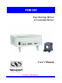
FSM-300
Fast Steering Mirror
& Controller/Driver
User’s Manual
For Motion, Think Newport™
FSM-300
Fast Steering Mirror & Controller/Driver
Warranty
Newport Corporation warrants that this product will be free from defects in
material and workmanship and will comply with Newport’s published specifications at the time of sale for a period of one year from date of shipment.
If found to be defective during the warranty period, then product will either be
repaired or replaced at Newport's option.
To exercise this warranty, write or call your local Newport office or representative,
or contact Newport headquarters in Irvine, California. You will be given prompt
assistance and return instructions. Send the product, freight prepaid, to the
indicated service facility. Repairs will be made and the instrument returned freight
prepaid. Repaired products are warranted for the remainder of the original
warranty period or 90 days, whichever first occurs.
Limitation of Warranty
The above warranties do not apply to products which have been repaired
or modified without Newport’s written approval, or products subjected to unusual
physical, thermal or electrical stress, improper installation, misuse, abuse, accident
or negligence in use, storage, transportation or handling.
This warranty also does not apply to fuses, batteries, or damage from battery
leakage.
THIS WARRANTY IS IN LIEU OF ALL OTHER WARRANTIES,
EXPRESSED OR IMPLIED, INCLUDING ANY IMPLIED WARRANTY OF
MERCHANTABILITY OR FITNESS FOR A PARTICULAR USE. NEWPORT
CORPORATION SHALL NOT BE LIABLE FOR ANY INDIRECT, SPECIAL,
OR CONSEQUENTIAL DAMAGES RESULTING FROM THE PURCHASE OR
USE OF ITS PRODUCTS.
First printing 2003.
2014 Newport Corporation, Irvine, CA. All rights reserved.
No part of this manual may be reproduced or copied without the prior written
approval of Newport Corporation.
This manual has been provided for information only and product specifications are
subject to change without notice. Any change will be reflected in future printings.
1791 Deere Ave.
Irvine, CA 92606
(949) 863-3144
P/N 40342-01, Rev. E
EDH0347En1010 – 03/14
P/N 40342-01, Rev. E
ii
FSM-300
Fast Steering Mirror & Controller/Driver
Table of Contents
Warranty
......................................................................................................................ii
EU Declaration of Conformity .................................................................................................. v
Preface
.....................................................................................................................vi
1.0
Safety Precautions ................................................................................. 1
1.1
General Description ......................................................................................................... 1
1.2
General Cautions ............................................................................................................. 2
2.0
Fast Steering Mirror Technology ........................................................ 4
3.0
Typical Specifications............................................................................ 7
3.1
FSM System .................................................................................................................... 7
3.2
Standard Mirror Options.................................................................................................. 7
3.3
FSM-CD300B Controller/Driver..................................................................................... 8
3.4
Bode Plots 8
3.5
Safe Operating Area ........................................................................................................ 9
4.0
Unpacking the FSM............................................................................. 11
4.1
Packing List ................................................................................................................... 11
4.2
Freeing the Mirror Head ................................................................................................ 11
4.3
Storing and Shipping the Mirror Head .......................................................................... 11
4.4
Replacing the Mirror ..................................................................................................... 12
5.0
System Components ............................................................................ 13
5.1
FSM Mirror Head Assembly ......................................................................................... 13
5.2
FSM-CD300B Controller/Driver................................................................................... 15
5.3
FSM Electronics ............................................................................................................ 17
5.4
FSM-CD300B Controller/Driver Cable Pin Connections ............................................. 18
5.5
Interface I/O Pin Connections ....................................................................................... 19
6.0
System Operation ................................................................................ 20
6.1
Installation Location & Ventilation ............................................................................... 20
6.2
Electrical Connections ................................................................................................... 20
6.3
Command Inputs ........................................................................................................... 21
6.4
Position Outputs ............................................................................................................ 21
6.5
Fault Indication.............................................................................................................. 22
iii
P/N 40342-01, Rev. E
FSM-300
Fast Steering Mirror & Controller/Driver
6.6
External Sensor Feedback Control Mode ...................................................................... 23
6.7
Open Loop Control Mode ............................................................................................. 24
6.8
Maintenance & Service ................................................................................................. 24
7.0
Appendices ........................................................................................... 26
7.1
Appendix A – Troubleshooting the FSM System.......................................................... 26
7.2
Appendix B – Abbreviations ......................................................................................... 26
Service Form ................................................................................................. 27
P/N 40342-01, Rev. E
iv
FSM-300
Fast Steering Mirror & Controller/Driver
EU Declaration of Conformity
v
P/N 40342-01, Rev. E
FSM-300
Fast Steering Mirror & Controller/Driver
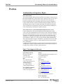
Preface
Confidentiality & Proprietary Rights
Reservation of Title
The Newport Programs and all materials furnished or produced in connection with
them ("Related Materials") contain trade secrets of Newport and are for use only in
the manner expressly permitted. Newport claims and reserves all rights and
benefits afforded under law in the Programs provided by Newport Corporation.
Newport shall retain full ownership of Intellectual Property Rights in and to all
development, process, align or assembly technologies developed and other derivative work that may be developed by Newport. Customer shall not challenge, or
cause any third party to challenge, the rights of Newport.
Preservation of Secrecy and Confidentiality and Restrictions to Access
Customer shall protect the Newport Programs and Related Materials as trade
secrets of Newport, and shall devote its best efforts to ensure that all its personnel
protect the Newport Programs as trade secrets of Newport Corporation. Customer
shall not at any time disclose Newport's trade secrets to any other person, firm,
organization, or employee that does not need (consistent with Customer's right of
use hereunder) to obtain access to the Newport Programs and Related Materials.
These restrictions shall not apply to information (1) generally known to the public
or obtainable from public sources; (2) readily apparent from the keyboard operations, visual display,
or output reports of the Programs; (3) previously in the possession of Customer or
subsequently developed or acquired without reliance on the Newport Programs; or
(4) approved by Newport for release without restriction.
Sales, Tech Support & Service
North America & Asia
Newport Corporation
1791 Deere Ave.
Irvine, CA 92606, USA
Sales
Tel.: (800) 222-6440
e-mail: [email protected]
Technical Support
Tel.: (800) 222-6440
e-mail: [email protected]
Service, RMAs & Returns
Tel.: (800) 222-6440
e-mail: [email protected]
Europe
MICRO-CONTROLE Spectra-Physics S.A.S
9, rue du Bois Sauvage
91055 Evry Cedex
France
Sales France
Tel.: +33 (0)1.60.91.68.68
e-mail: [email protected]
Sales Germany
Tel.: +49 (0) 61 51 / 708 – 0
e-mail: [email protected]
Sales UK
Tel.: +44 (0)1635.521757
e-mail: [email protected]
Technical Support
e-mail: [email protected]
Service & Returns
Tel.: +33 (0)2.38.40.51.55
P/N 40342-01, Rev. E
vi
FSM-300
Fast Steering Mirror & Controller/Driver
Technical Support Information
When calling Newport Technical Support with a technical issue or problem, please
be prepared to provide the following information:
•
•
•
•
•
•
•
•
Your contact information.
System serial number or original order number.
Description of problem.
Environment in which the system is used.
State of the system right before the problem.
Can you identify anything that may have caused the problem?
Can the system continue to operate, or is it non-operational?
Frequency and repeatability of problem.
Service & RMA Information
The user should not attempt any maintenance or service of the FSM Fast Steering
Mirror System beyond the procedures outlined in this manual. Any problem that
cannot be resolved should be referred to Newport’s Service & Returns Department,
and any failed product should be returned to that department for service. A Return
Materials Authorization (RMA) number must be obtained in advance and should
be stated on the outside of the shipping box. To obtain an RMA number, please fill
out and fax back the Return Material Authorization Request form included at the
end of this manual.
Packaging for Returns
Any FSM Fast Steering Mirror Head or FSM-CD300B Controller/Driver being
returned under an RMA must be securely packaged for shipment. The RMA
number must be stated on the outside of the shipping box. If possible, reuse the
original factory packaging. The mirror must be secured for shipment. Please
contact Newport’s Service & Returns Department if you no longer have the
original shipping restraints for the mirror.
vii
P/N 40342-01, Rev. E
FSM-300
P/N 40342-01, Rev. E
Fast Steering Mirror & Controller/Driver
viii
FSM-300
Fast Steering Mirror & Controller/Driver
FSM-300
Fast Steering Mirror & Controller/Driver
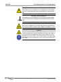
1.0
Safety Precautions
1.1
General Description
Observe these Cautionary Notes when setting-up operating or servicing this
system:
• Heed all Cautions marked on the unit and in the operating instructions.
• Do not use this equipment in or near liquids.
• Do not operate this equipment in an explosive atmosphere.
• This product is electrically compatible of operating with virtually all the
delivered electrical service anywhere in the World. The detachable Electrical
Power Cord used must have plug that matches the local on-site receptacles and
is approved by local EU Member authorities.
• Only plug the controller/driver unit into an EARTH grounded Electrical AC
receptacle.
• Route power cords and cables where they are not likely to be damaged.
• Disconnect power before cleaning the controller/driver unit. Do not use liquid
or aerosol cleaners.
• Only qualified service personnel should open the case of the controller/driver.
There are no user-serviceable components inside unit.
• Dangerous voltages associated with the 100–240 VAC power supply are
present inside controller/driver unit. To avoid injury, do not touch exposed
connections or components while power is on.
• To avoid fire hazard, use only the specified fuse(s) with the correct type
number, voltage and current ratings. Only qualified personnel should replace
fuses.
• Qualified service personnel should perform a safety check after any service.
• The Fast Steering Mirror is only for use with Lasers of Class 1, Class 1M,
Class 2, Class 2M and Class 3R. To avoid potential Hazardous Conditions for
Personnel and Possible Property Damage, DO NOT USE WITH CLASS 3B or
CLASS 4 LASERS.
1
P/N 40342-01, Rev. E
FSM-300
Fast Steering Mirror & Controller/Driver
WARNING
RISK OF EYE DAMAGE OR BLINDNESS, RISK OF INJURY TO THE
SKIN.
RISK OF FIRE AND PROPERTY DAMAGE.
DO NOT USE WITH CLASS 3B OR CLASS 4 LASERS AS DEFINED BY
EN 60825-1.
ALWAYS WEAR APPROVED EYE PROTECTIVE GLASSES IN LASER
AREA.
1.2
General Cautions
Observe these cautions when operating or servicing this equipment:
• Handle equipment with care, like other delicate electronic equipment.
• To prevent damage to equipment when replacing fuses, locate and correct the
problem that caused the fuse to blow before re-applying power.
• Use only specified replacement parts.
• Follow precautions for static-sensitive devices when handling electronic
circuits.
• This product should only be powered as described in this manual.
• If this equipment is used in a manner not specified within this manual, the
protection provided by the equipment may be impaired.
• Do not position this equipment in a location that would make it difficult to turn
off power to the equipment or disconnect the AC power cord.
• When the Fast Steering Mirror is used with lasers, care must be taken to avoid
any hazardous conditions involving eye damage, skin damage or cause of fire.
• The Fast Steering Mirror is not intended for use with Class 3B and 4 lasers.
Serious injury, blindness or a fire may result if used with Class 3B or Class 4
Lasers.
Modifications that affect any aspect of the product's performance or intended
functions may require re-certification and re-identification of the product. Consult
NEWPORT prior to making any modifications.
WARNING
AC power line voltages are present inside the controller/driver unit.
To avoid possibility of electrical shock, refer all service to qualified personnel.
WARNING
If the Fast Steering Mirror is used with lasers, avoid possible eye damage by
not looking into the laser beam, and avoid possible burns or skin damage by
taking precautions not to allow the laser beam to come in contact with persons
area. All persons in the designated Laser Area are required to wear Certified
Protective Eye Wear approved for the Type and Class of Laser(s) in
operation.
P/N 40342-01, Rev. E
2
FSM-300
Fast Steering Mirror & Controller/Driver
CAUTION
Static-sensitive electronic equipment. Wear grounding strap when handling
electronic circuit boards and components found inside the controller/driver
unit.
FRAME & CHASSIS TERMINAL
Static-sensitive electronic equipment. Wear grounding strap when handling
electronic circuit boards and components found inside the controller/driver
unit. .
WARNING
Use of controls, adjustments or procedures other than those specified herein
may result in hazardous radiation exposure, blindness, skin damage or a fire.
WARNING
The use of optical instruments with this product will increase eye hazard. Do
not allow the FSM to direct the laser beam in the direction of other people or
at reflective surfaces that might cause exposure to the human-eyes. Do not
mount the laser and/or FSM at eye level. All personnel to wear Approved Eye
Ware suitable for the Type and Class of Laser(s) operating in the Designated
Laser Area.
3
P/N 40342-01, Rev. E
FSM-300
2.0
Fast Steering Mirror & Controller/Driver
Fast Steering Mirror Technology
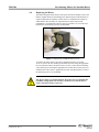
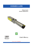
Originally conceived for military/aerospace applications such as high-speed target
tracking and secure satellite-to-satellite communication, fast steering mirror
technology has been developed to the point where it is economically viable for
widespread commercial use in dynamic mirror alignment applications. This
technology can be used to stabilize laser beams (Figure 1), track work pieces for
precision laser micro-machining, scan laser beams for real-time confocal
microscopy, track optical receivers for laser free-space communication, and
increase sharpness in sophisticated imaging systems.
Figure 1: Two fast steering mirrors used to compensate for input tilt errors.
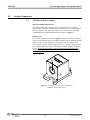
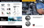
A practical fast steering mirror head is shown in
. There are eight basic head components: voice-coil actuators, mirror, mirror
carrier, flexure suspension, frame, housing, internal position sensors, and position
P/N 40342-01, Rev. E
4
FSM-300
Fast Steering Mirror & Controller/Driver
sensor electronics. These components work with the controller to produce the
precision rotation and speed characteristic of these devices.
Figure 2: FSM mirror head assembly.
The voice coil actuators 1 provide the torque necessary to tilt the mirror substrate.
Four actuators are mounted behind the mirror, one in each quadrant. Voice coils
are connected in pairs along the diameter of the mirror and operate in a push/pull
manner, rotating the mirror about the axis that bisects them. Two actuator pairs
(four coils) plus a coordinate transformation are used to produce two orthogonal
rotations θx and θy about the X and Y axes. The high force generated by four
distributed actuators rotates large mirrors more effectively than the one actuator
used in galvanometer scanners. The distributed force combined with thick optics
enables the FSM mirror head to preserve static and dynamic surface flatness,
excellent positional resolution, large angular range and rapid motion. The coil
portion of the actuators is placed within the support structure and contacted to a
heat sink such that heat produced in the actuator is dissipated far from the mirror
surface, thus minimizing thermal distortions.
A flexure suspension system is used to support the mirror carrier that holds the
mirror. This system allows free rotation about orthogonal X and Y-axes while
constraining side-to-side motion, rotation about the normal (Z) axis
and “pogo” motion along the Z-axis. Different types of flexure systems are used
for different FSM applications. Some flexure systems are stiff (large spring
constant) and offer a relatively stable and repeatable power-off mirror position.
One downside to stiff flexures is the increased current necessary to move the
mirror. The FSM series of mirror heads is designed around a small spring constant
to keep the current and the consequential heating to a minimum. As expected, the
FSM in power-off status is greatly affected by external effects such as gravity and
vibrations. This power-off susceptibility must be taken into consideration when
designing the mirror into an integrated system. Proper turn-on and turn-off
procedures should be followed to ensure that light is only applied to the mirror
when it is powered and under the control of either internal or external position
feedback.
A position transducer is included in the FSM mirror head to provide position
feedback with reference to the support frame. This transducer senses the angle of
the mirror carrier and transfers this information to the position sensor electronics
board located within the mirror head. This board processes the position
1 Historically, voice coils were first used in loudspeakers, from which they derive their name. A linear voice coil consists of a tubular coil
of wire situated within the radially oriented magnetic field of a permanent magnet. When current flows through the coil, a force is
generated that causes axial (linear) motion. This linear motion is then used to move the mirror.
5
P/N 40342-01, Rev. E
FSM-300
Fast Steering Mirror & Controller/Driver
information and outputs a differential voltage, A-B. This signal is sent to the FSMCD300B controller/driver to provide the appropriate feedback current to the voice
coils.
Two significant advantages of FSM technology are derived from the flexure
suspension:
1.
FSM flexure suspension eliminates bearing surfaces often used with
galvanometer scanners, and eliminates their associated stiction and wear.
With bearing surfaces, stiction interrupts the smooth motion of the actuator
and limits its accuracy (smallest incremental motion). Wear sets a device
lifetime based on the number of commanded cycles. On the other hand,
properly designed flexure suspensions have infinite cycle lifetimes.
2.
FSM flexure suspension delivers motion about two axes intersecting at a
common pivot point. When the pivot point is placed at the surface of the
mirror, the design is called gimbaled. The advantage is that a mirror-centered
optical beam does not experience a change in path length with angular
rotation. The FSM is such a gimbaled design. On the other hand, the two
galvanometers and two mirrors used in dual-axis galvanometer-based designs
make it impossible for the axes to intersect, with no common pivot point and
no gimbaled motion. Relay optics can solve the problem by imaging the first
galvo mirror onto the second, but at substantially increased complexity and
cost. The lack of a common pivot point complicates post-objective and preobjective scanning applications, requiring a compromised optical design to
accommodate the separate rotation axes.
The FSM-300 System comes with a 1” (25.4 mm) diameter, λ/10 Pyrex mirror,
which is available with a choice of reflective coatings for different wavelengths.
The mirror is bonded to an aluminum carrier, which is user replaceable in the event
that wavelength requirements are changed or the mirror surface has been damaged.
Two standard mirrors can be specified at the time of order:
• 10D20ER.1: Enhanced Aluminum Coating. Multi-layer dielectric stack
deposited over an aluminum film for improved performance in the visible and
enhanced durability of the coating. Average reflectivity is
> 93% from 450-700 nm.
• 10D20ER.4: Protected Gold Coating. Multi-layer dielectric stack deposited
over a gold film for excellent reflectivity from the near IR to the far IR.
Average reflectivity is > 96% from 650- 1700 nm and > 98% from 1.7-2.0 µm.
P/N 40342-01, Rev. E
6
FSM-300
3.0
Fast Steering Mirror & Controller/Driver
Typical Specifications
3.1
FSM System
Number of Axes
Angular Range from ±10 V
Resolution
Repeatability
Accuracy From ±26.2 mrad, 20°C(1,2)
Linearity From ±26.2 mrad, 20°C(1,2)
Closed-Loop Amplitude Bandwidth(2) (-3 dB)
Closed-Loop Phase Bandwidth(2) (60° lag)
Response Flatness(2)
Noise Equivalent Angle (1 Hz to 10 kHz)
Resolution of Local Position Sensor
Quiescent Power at FSM Assembly
Operating Temperature Range(2)
Storage Temperature Range
Warm-up Time for Mirror Stability(2) at 20°C
Mirror Thermal Drift(2)
Optical Axis Location
Mirror Head Weight with Base
Interconnect Cable Length
3.2
FSM-300
2 (tip-tilt)
± 26.2 mrad (± 1.5°), mechanical(1)
≤ 1 μrad rms, mechanical(1)
≤ 3 μrad rms, mechanical(1)
≤ 0.262 mrad (0.015°),
mechanical(1)
≤ 1.0%
600 Hz at 10 mV (typical)
250 Hz (typical)
Peaking ≤ 3 dB
≤ 3 μrad rms
≤ 0.5 μrad
≤ 5 W at any angle ± 26.2 mrad
0 to 50°C (32 to 122°F)
-20 to 55°C (-4 to 131°F)
≤ 10 minutes
≤ 5 μrad/°C, mechanical(1)
1.5 in. (38.1 mm) high, centered
left-to-right
15.3 oz (434 g)
9.8 ft (3 m)
Standard Mirror Options
Mirror Substrate Material
Mirror Retaining Mechanism
Mirror Pivot Point (centered on mirror)
Mirror Diameter
Mirror Thickness
Mirror Wedge
Clear Aperture(3) at 0° angle of incidence
Clear Aperture(3) at 45° angle of incidence
Surface Flatness(3) (after coating and bonding)
Surface Quality(3)
Reflectivity, Standard Coatings(3)
ER.1 Coating: Enhanced Aluminum
ER.4 Coating: Protected Gold
Additional coating options
FSM-300
Pyrex
Mirror bonded to aluminum carrier
(user replaceable).
Gimbaled 12.19 mm behind mirror
surface
25.4 mm
6.0 mm
≤ 5 arc min
≥ 20.3 mm
≥ 14.4 mm
≤ λ/10 at 632.8 nm over clear
aperture
15-5 scratch-dig
> 93%, 450-700 nm
> 96%, 650- 1700 nm; > 98% from
1.7-2.0 µm
Please contact Newport.
1) Optical angular range is equal to twice the mechanical angular range.
2) Measured under position output control. Optical closed-loop performance is also
determined by external feedback electronics.
7
P/N 40342-01, Rev. E
FSM-300
Fast Steering Mirror & Controller/Driver
3) Optical parameters apply to central 80% of mirror aperture.
NOTES
Performance data is based upon well-defined, smooth, D-A sine wave inputs.
Alternate inputs (square waves, triangle waves, low resolution D-A sine
waves) are addressed in section 6.3
3.3
FSM-CD300B Controller/Driver
Command Input and Position Output
Peak Operating Power to Mirror
Continuous Max Operating Power to Mirror
Thermal Protection
Operating Temperature(2)
Storage Temperature
Use Location
Relative humidity
Operating altitude
Power
Current consumption (typical)
Fuses
Weight
Case Dimensions (excluding connectors)
3.4
Analog, ±10 V = ±26.2 mrad
30 W
15 W
60 °C at mirror coil
0 to 35 °C (32 to 95 °F)
-20 to 55 °C (-4 to 131 °F)
Indoor use only
< 95%, non-condensing
< 3,000 m (10,000 ft)
100-240 Vac ±10%, 47-63 Hz
0.40 A @ 100 Vac,
0.25 A @ 240 Vac
2 ea, “slo-blo” (T), 5 x 20 mm, rated
2.5 A, 250 Vac
5.5 lbs (2.5 kg)
3.9” x 9.0” x 10.0” [h x w x d]
(100 x 229 x 254 mm)
Bode Plots
Figure 3: Typical gain response Bode plot for small-angle excitation.
Amplitude 0.262 mrad.
P/N 40342-01, Rev. E
8
FSM-300
Fast Steering Mirror & Controller/Driver
Figure 4: Typical phase angle Bode plot for small-angle angle excitation.
Amplitude 0.262 mrad.
3.5
Safe Operating Area
Figure 5: Typical shut-down curve as a function of amplitude and frequency at
20 ºC. Continuous operation is “safe” below the line. Derate for higher ambient
temperatures.
9
P/N 40342-01, Rev. E
FSM-300
Fast Steering Mirror & Controller/Driver
FSM operation is limited to an envelope of mirror deflection amplitude versus
frequency. For the FSM-300, amplitude is mechanically limited to 26 mrad up to
40 Hz. Above 40 Hz, long-term, continuous operation is limited by the allowed
thermal loading of the drive coils. The latter is approximately proportional to
signal amplitude times frequency squared. This means that above 40 Hz, the
maximum allowed amplitude is inversely proportional to the square of frequency.
If the coils reach a temperature warning threshold, as measured by thermistors, a
yellow warning light labeled CURR comes on; however, the system continues to
operate as before. If the coils reach an upper temperature shut-off threshold, a red
warning light labeled TEMP comes on, and the mirror reverts to the unpowered
state. Upon cooling of the coils, the red light will
go off, and the system will automatically resume normal operation.
If the yellow warning light comes on during normal, continuous operation,
consider decreasing the drive signal frequency and/or amplitude to prevent
overheating of the drive coils and avoid a possible thermal shutdown.
P/N 40342-01, Rev. E
10
FSM-300
4.0
Fast Steering Mirror & Controller/Driver
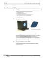
Unpacking the FSM
4.1
Packing List
Included with each FSM System are the following items:
• FSM-300 Mirror Head
• FSM-CD300B controller/driver
• FSM-CD300B controller/driver interconnect cable, 3 m
• Allen wrench for protective cover of Mirror Head
• Instruction manual
4.2
Freeing the Mirror Head
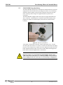
Figure 6: Protective lens tape and metal cover for mirror.
For shipment, the FSM mirror is secured by adhesive lens tape plus an oval, hinged
metal cover, as illustrated in Figure 6. To free the mirror, loosen the two
diagonally opposed retaining screws so that the protective cover can be pivoted for
easy removal. The appropriate Allen wrench is supplied with the mirror head.
Once the cover is removed, gently pull off the lens tape. Store the lens tape inside a
clean polyethylene bag for possible later use.
4.3
Storing and Shipping the Mirror Head
When the mirror head is not in use, replace the oval protective cover so that
it covers and protects the mirror. If you ever have to ship the mirror head, also
reposition the lens tape.
11
P/N 40342-01, Rev. E
FSM-300
Fast Steering Mirror & Controller/Driver
4.4
Replacing the Mirror
The FSM is designed so that the user can replace the mirror assembly in the event
that the original mirror has been damaged or different spectral characteristics are
required. FSM mirrors bonded to a metal carrier are available from Newport as
subassemblies. Hex wrenches are required tools for mirror removal and
reinstallation. The FSM-300 requires 0.050” hex wrenches. Use of Loctite 222
thread locker on mounting screws is recommended.
Figure 7: Replacement of FSM-300 mirror carrier.
To remove the mirror carrier, first remove the front protective cover plate.
To do so, remove the four retaining socket head cap screws using the appropriate
hex wrench. Then remove the mirror carrier. To do so, remove the four retaining
socket head cap screws using the appropriate hex wrench. Reverse the process to
install the new mirror carrier. Application of Loctite 222 thread locker to each of
the mounting screws is recommended.
CAUTION
The mirror surface is extremely delicate. Wear latex gloves to minimize the
possibility of fingerprints. Be extremely careful not to scratch the mirror
surface with the wrench or cap screws.
P/N 40342-01, Rev. E
12
FSM-300
5.0
Fast Steering Mirror & Controller/Driver
System Components
5.1
FSM Mirror Head Assembly
Envelope and Mounting Interface
The FSM head assembly conforms to both 1-inch and 25 mm on-center hole
patterns and is configured for mounting at 0° and 45° angles on a standard optical
table or breadboard. The optical axis height is 1.50” when mounted. The FSM300head dimensions and mechanical interface are shown in Figure 9.
Rotation Axes
The X and Y rotation axes are shown in Figure 8. Note that X rotation is about the
X-axis. The definition of these axes should be considered in the mechanical layout
and the coordinate frame definitions in the optical layout. The polarity of the
mirror rotation complies with the “right hand rule,” i.e., positive voltage applied at
the command input creates positive (clockwise) rotation as viewed looking along
the axis. If an external quad cell or lateral effect detector is used as the angle
sensor, the sensor axes of the detector must be aligned to the rotation axes of the
FSM mirror head.
Figure 8: X and Y axes corresponding to FSM input
commands and position outputs.
13
P/N 40342-01, Rev. E
FSM-300
Fast Steering Mirror & Controller/Driver
Figure 9: FSM-300 Mirror Head Housing.
P/N 40342-01, Rev. E
14
FSM-300
Fast Steering Mirror & Controller/Driver
5.2
FSM-CD300B Controller/Driver
The FSM-CD300B controller/driver establishes the feedback interface between the
angle position sensors and the drivers providing current to the voice coils that tip
and tilt the mirror assembly. It also provides an interface between the user and
mirror, allowing control voltages to be applied and mirror positions to be
ascertained.
The FSM-CD300B is equipped with a universal power supply that handles 100240 V, 50/60 Hz. A standard power cord interface (IEC 950) facilitates power
plugs that are suitable for most European, North American, and Pacific Rim
Countries.
Figure 10: Removal of Fuse Block.
A fuse block is located above the power connector and utilizes two 5 x 20 mm
slow-blow glass fuses rated 2.5 A, 250 Vac. To remove the fuse block, first unplug
the power cord, compress the two plastic tabs on the right and left sides of the fuse
block, and pull out the fuse block. No tools are needed. When reinserting the fuse
block, make sure that the alignment tab is at the bottom.
WARNING
Dangerous voltages are present inside the FSM-CD300B controller/ driver
when connected to AC line power. To avoid the possibility of electrical shock,
always unplug the unit from AC line power when checking or changing fuses.
15
P/N 40342-01, Rev. E
FSM-300
Fast Steering Mirror & Controller/Driver
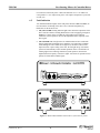
Figure 11: FSM-CD300B Controller/Driver.
P/N 40342-01, Rev. E
16
FSM-300
Fast Steering Mirror & Controller/Driver
5.3
FSM Electronics
The FSM electronics are housed in two locations:
1. The FSM Mirror Head containing the voice coil actuators, the angle position
sensors and the position sensor electronics.
2. The FSM-CD300B Controller/Driver containing the control circuits (PIDs,
calibration factors), current drivers, power supply, user interface and interlocks.
The mirror head is connected to the controller/driver by a 3-meter long,
15-pin cable. The controller has a universal power supply that can be plugged
directly into most wall outlets. The appropriate power cord for the destination
country should be included with your controller. If the correct cord is not present
please contact your local Newport representative for assistance.
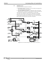
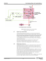
Figure 12: Functional Block diagram of FSM-CD300B controller/driver.
17
P/N 40342-01, Rev. E
FSM-300
Fast Steering Mirror & Controller/Driver
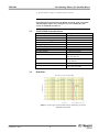
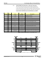
5.4
FSM-CD300B Controller/Driver Cable Pin Connections
The electrical connection between the mirror head and the controller/driver
is via a 15-pin D-connector terminated cable. This cable attaches between the
connector located on the back of the mirror head and the connector labeled “FSM”
on the front of the FSM-CD300B controller/driver. The position sensors and voice
coils are located on A and B axes (at 45° to the X and Y axes). A coordinate
transform is done in the controller/driver to produce X and Y axis rotations.
Pin
Pin
Controller FSM Head
Name
Type
Controller
Description
1
6
+15VA
DC power
FSM positive 15V power
2
11
-15VA
DC power
FSM negative 15V power
3
4
2
8
BB_RTN
Analog input
Analog output
B axis position sensor negative (±10V)
B axis actuator drive return
5
6
13
4
B_OUT
A-
Analog output
Analog input
B axis actuator drive output
A axis position sensor negative (±10V)
7
10
A_RTN
Analog output
A axis actuator drive return
8
9
15
1
A_OUT
GND
Analog output
Analog ground
A axis actuator drive output
FSM ground reference and power return
10
11
7
12
B+
B_TEMP_RTN
Analog input
Analog ground
B axis position sensor positive (±10V)
B axis temperature sensor return (Analog Ground)
12
3
B_TEMP
Analog input
13
14
9
14
A+
A_TEMP_RTN
Analog input
Analog ground
15
5
A_TEMP
Analog input
B axis temperature sensor signal
A axis position sensor positive (±10V)
A axis temperature sensor return (Analog Ground)
A axis temperature sensor signal
Table 1: FSM pinout descriptions of 15-pin interface cable.
Figure 13: FSM pinout diagram of 15-pin interface cable.
P/N 40342-01, Rev. E
18
FSM-300
Fast Steering Mirror & Controller/Driver
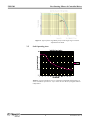
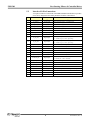
5.5
Interface I/O Pin Connections
A 25-pin D-connector on the front of the FSM-CD300B controller/driver provides
access to key diagnostic and control parameters from the control board.
Pin
Name
Type
1
Y_CMD(+)
Analog Input
Y-Axis Command Signal, ±10V differential
2
Y_CMD(-)
Analog Input
Y-Axis Command Signal, ±10V differential
3
X_CMD(+)
Analog Input
X-Axis Command Signal, ±10V differential
4
X_CMD(-)
Analog Input
X-Axis Command Signal, ±10V differential
5
Y_ERR
Analog Output
6
GND
Ground
7
X_ERR
Analog Output
8
GND
Ground
9
Y_OL_SW
Digital Input
Y-Axis Open Loop Selector Switch Input
(0V = closed loop; 5V, 5 mA = open loop)
10
X_OL_SW
Digital Input
X-Axis Open Loop Selector Switch Input
(0V = closed loop; 5V, 5 mA = open loop)
11
Y_EXTFB(+)
Analog Input
Y-Axis External Feedback Input, ±10V differential
12
Y_EXTFB(-)
Analog Input
Y-Axis External Feedback Input, ±10V differential
13
NC
No Connection
No Connection
14
NC
No Connection
No Connection
15
X_EXTFB(+)
Analog Input
16
X_EXTFB(-)
Analog Input
X-Axis External Feedback Input, ±10V differential
External Feedback Selector Switch Input
(0V = internal; 5V, 5 mA = external)
17
INT/EXT_SW
Digital Input
18
Y_POS_OUT
Analog Output
19
GND
Ground
20
X_POS_OUT
Analog Output
21
GND
Ground
22
Y_OL_CMD
Analog Input
23
GND
Ground
24
X_OL_CMD
Analog Input
25
GND
Ground
Description
Y-Axis Error Voltage Output
Ground
X-Axis Error Voltage Output
Ground
X-Axis External Feedback Input, ±10V differential
Y-Axis Position Output
Ground
X-Axis Position Output
Ground
Y-Axis Open-Loop Command Voltage, ±10V, Single-Ended
Ground
X-Axis Open-Loop Command Voltage, ±10V, Single-Ended
Ground
Table 2: Front Panel Interface I/O Connector Pinout.
19
P/N 40342-01, Rev. E
FSM-300
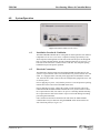
6.0
Fast Steering Mirror & Controller/Driver
System Operation
Figure 14: FSM-CD300B controller/driver.
6.1
Installation Location & Ventilation
The FSM-CD300B controller/driver is designed for indoor operation in an ambient
temperature of 0 to 35°C (32 to 95°F). Component cooling is provided by a fan,
which aspirates air through slots in both sides of the unit and ejects air through the
back. To assure adequate airflow, provide a minimum clearance of 25 mm (1”) on
both sides of the unit and 2” (50 mm) in back of the unit. Also, adequate spacing
behind the fan provides quieter operation.
6.2
Electrical Connections
The FSM mirror head is interfaced to the FSM-CD300B controller/driver by the
system’s 15-pin connector cable. The controller/driver is powered from an AC wall
outlet. It is equipped with a universal power supply that accommodates 100-240
Vac, 50/60 Hz. No switch or fuse needs to be changed when going from 100 to 120
or 240 Vac power.
Prior to applying AC power, verify that the protective cover and protective packing
material have been removed from the FSM mirror head.
Prior to applying AC power, connect the system’s15-pin connector cable to the
FSM mirror head and FSM-CD300B controller/driver. If you later need to remove
the 15-pin connector cable, first remove AC power. Connecting and disconnecting
the 15-pin connector cable in the absence of power will avoid making or breaking
powered signal connections.
Once connected to the mirror head and to the wall outlet, the FSM-CD300B
controller/driver may be turned on using the POWER switch located on the left
side of the front panel (see Figure 16).
P/N 40342-01, Rev. E
20
FSM-300
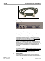
Fast Steering Mirror & Controller/Driver
Figure 15: 15-pin interface cable from controller to mirror head.
6.3
Command Inputs
Figure 16: Front panel I/O connections.
Control voltages called “Command Inputs” are used to direct the mirror to
specified angular positions around two orthogonal axes. These voltages are
normally applied to the two BNC connectors labeled COMMAND INPUTS X and
Y on the front panel, but can also be applied to the 25-pin INTERFACE I/O
connector on the front panel. Please see Figure 16. Scaling is
set so that ±10V DC offsets correspond to the full-scale motion of ±1.5° (±26
mrad) mechanical angular range on each axis. A command voltage of zero will
bring the mirror to the powered-on null position for that axis. The X and Y inputs
are differential. Neither lead of the BNC connector is grounded.
Certain FSM system output results (overshoot, settling time and point-to-point
travel path) are dependant upon the input waveform, amplitude and frequency of
the signal. Due to the many possibilities, customers are encouraged to experiment
with their particular drive signal parameters when optimizing their application. As
a practical guide, a well-defined, smooth sinewave input will generate the best
output results.
Self-heating of the mirror drive coils is proportional to command signal amplitude
and to the square of frequency. Consult Figure 5 in the specification section of this
manual for the Safe Operating Area before driving your FSM system near its
frequency versus amplitude maxima. The gain and phase response as a function of
frequency for typical FSM systems are shown in Figures 3 & 4.
6.4
Position Outputs
If confirmation of mirror position is desired, the position angle sensors can be
monitored at the Position Output pins (pins 18 and 20) of the 25-pin INTERFACE
21
P/N 40342-01, Rev. E
FSM-300
Fast Steering Mirror & Controller/Driver
I/O connector on the front panel. A full-scale deflection of ±1.5º on either axis
corresponds to a ±10 V output swing. Zero volts output corresponds to a poweredon null, or 0º.
6.5
Fault Indication
Two LED fault indicator lights on the front panel, labeled CURR and TEMP, are
used to indicate overheating of the drive coils, as measured separately by
thermistors for the X and Y axes.
• The yellow CURR warning indicator light comes when the temperature of the
drive coils has reached a warning threshold as a result of applying too high an
RMS drive current. In the event that the yellow light comes on during
continuous system operation, decrease the amplitude and/or frequency of the
drive signal.
• The red TEMP shut-off light comes on when thermistors have reached the
shut-off temperature threshold, above which the over-temperature condition
would damage the coils. While the red light is on, the mirror will be in the
unpowered state. Upon cooling of the coils, the red light will go off, and the
system will automatically resume normal operation. In the event that the red
warning light comes on during continuous system operation, decrease the
amplitude and/or frequency of the drive signal. Also check for possible inverse
polarity of an External Feedback signal.
Figure 17: Model FSM-CD300B controller/driver front and rear panels.
P/N 40342-01, Rev. E
22
FSM-300
Fast Steering Mirror & Controller/Driver
6.6
External Sensor Feedback Control Mode
The Model FSM-CD300B controller/driver can be used in an External Sensor
Feedback Control mode with position feedback from an external sensor, such as a
quad cell or lateral effect cell. This allows the FSM to lock a laser beam onto a
target such as the center of a quad cell. The default alternative is the Internal
Control mode, which utilizes a quad cell sensor built into the mirror head and feeds
the error signal back to the controller/driver via the system’s 15-pin, 3-foot
interface cable.
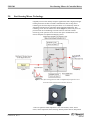
A beam stabilization system with external position feedback sensing is shown in
Figure 18. To switch system operation to External Feedback Control from the
Internal Control, a high TTL-level signal must be applied to the INT/EXT selector
switch (Pin 17) of the 25-pin INTERFACE I/O connector. External Feedback
inputs can then be applied to Pins 11, 12, 15 and 16. Returning the signal on Pin 17
to a low state will switch the FSM back to Internal Control.
In the illustration in Figure 18, a Logic Unit (supplied by the user) provides the
TTL-level signal for locking the FSM onto the quad cells. The sum of
the outputs from the quad cell determines whether sufficient light is on the
detector. If light is sufficient, the Logic Unit switches the FSM’s to External
Feedback Control and cancels out the tilt errors. If light is insufficient, the Logic
Unit keeps the FSM’s on Internal Control and flags an error to the operator.
The external feedback signals should be scaled so that ±10V yields ±26 mrad of
mechanical rotation. Care needs to be taken to align the external sensors so that X
and Y rotation axes of the FSM correspond to the correct X and Y outputs of the
quad / lateral effect cell amplifier.
Reference position voltages can be applied to the Command Inputs so that if the
INT/EXT selector switch voltage input returns to Internal Control mode, the FSM
will move to a defined position. Otherwise the mirror will return to the powered-on
null position.
See Application Note 23 in www.newport.com for details of active beam
stabilization with external feedback signal using Position Sensing Detectors (PSD).
23
P/N 40342-01, Rev. E
FSM-300
Fast Steering Mirror & Controller/Driver
Figure 18: FSM configured with external feedback
sensor for laser beam stabilization.
6.7
Open Loop Control Mode
The Model FSM-CD300B controller/driver can be used in Open Loop mode,
which does not make use of External or Internal feedback signals. The Open Loop
mode is selected by applying a high TTL-level signal X_OL_SW selector switch
for X (Pin 9) and/or Y_OL_SW selector switch for Y (Pin 10). The Open Loop
command signals are applied to the X_OL_CMD input for X (Pin 22) and/or
Y_OL_CMD input for Y (Pin 24). These input are single-ended. Ground pins are
adjacent on Pins 23 and 25.
The Open Loop mode allow users to develop their own control systems.
In this mode, the FSM-CD300B controller/driver is only used as an
amplifier/driver, which converts voltage signals to current to drive the coils.
6.8
Maintenance & Service
Clanging sounds from the mirror head are normal when the unit is first turned on,
when a high step function is applied, or when the mirror is unpowered and is
shaken by hand. Such sounds are normal and occur when the mirror hits its hard
stops. They are not a sign of malfunction.
The FSM system does not require periodic maintenance or calibration. There is no
reason for a user to ever open the FSM-CD300B Controller/Driver unit. Opening
the unit would break a label and void the warranty. The only reason for a user to
open the FSM Mirror Head would be to replace the mirror. Any repairs, if
necessary, are to be done by Newport Corporation.
To clean the FSM-CD300B Controller/Driver unit, first unplug the unit. Then wipe
the exterior using a damp, soft cloth. Do not use solvents or detergents.
P/N 40342-01, Rev. E
24
FSM-300
Fast Steering Mirror & Controller/Driver
The best way to maintain cleanliness of the mirror is to protect it from dirt
in the first place. If the Mirror Head Assembly is to be stored, always install the
protective metal cover, as described in the section “Unpacking the FSM.” Also,
store the Mirror Head Assembly in a hermetically sealed zipped bag.
The mirror surface is delicate and scratches easily. A qualified optics professional
should do any mirror cleaning. To remove loose dust, gently blow across the
optical surface using a can of optical-grade compressed air. You may also gently
brush the surface with a clean, optical-grade dust brush.
In case of heavy contamination that would interfere with the operation of the FSM
system, a qualified optics professional may remove the front cover and attempt to
use some of the techniques described in the section “Care & Cleaning of Optics”
on www.newport.com
In case of any mechanical contact with the optical surface, some scratches
are unavoidable.
25
P/N 40342-01, Rev. E
FSM-300
7.0
Fast Steering Mirror & Controller/Driver
Appendices
7.1
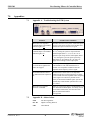
Appendix A – Troubleshooting the FSM System
Problem
Possible Cause & Solution
Mirror does not respond to
command inputs. Green PWR
indicator light is off.
Controller does not receive power. Assure that power
plug is live, that power switch is ON, and that fuses
(located above power connector) are good.
Mirror does not respond to
command inputs. Green PWR
indicator light is on.
+5V is applied to the INT/EXT selector switch input
(Pin 17), causing the system to expect External
Feedback inputs (Pins 11, 2, 15, 16). Or +5V is
applied to Open Loop selector switch inputs (Pins 9
or 10), causing the system to expect Open Loop
inputs (Pins 22, 24). Remove the +5V source or
supply control voltages on the required pins.
Yellow CURR indicator LED
is on. The drive signals to the
mirror are clipped.
The attempt is made to apply to much RMS current
to the FSM drive coils, which would create a
potential over-temperature condition. Decrease
amplitude and/or frequency of drive signal.
Red TEMP indicator LED is
Thermistors have detected an over-temperature
on. Mirror does not respond at condition of the drive coils because these are being
all.
driven too hard. Decrease amplitude and/or frequency
of drive signal. Also check for possible inverse
polarity of an External feedback signal. System will
automatically resume normal operation once coils
have cooled.
Mirror moves in opposite
direction of intended.
7.2
P/N 40342-01, Rev. E
Polarity is reversed at X and Y Command Inputs or X
and Y External Feedback Inputs. To remedy, reverse
your electrical connections, since the above four
inputs are differential without
a fixed ground.
Appendix B – Abbreviations
FSM
Fast Steering Mirror
D-A IR
Digital to Analog Infrared
NIR
Near Infrared
26
FSM-300
Fast Steering Mirror & Controller/Driver
Service Form
Your Local Representative
Tel.: ___________________
Fax: ___________________
Name: _________________________________________________
Company: ______________________________________________
Return authorization #: ________________________________
(Please obtain prior to return of item)
Address: ________________________________________________
Date: ______________________________________________
Country: ________________________________________________
Phone Number: ______________________________________
P.O. Number: ____________________________________________
Fax Number: ________________________________________
Item(s) Being Returned:____________________________________
Model#: ________________________________________________
Serial #: ____________________________________________
Description: ____________________________________________________________________________________________________
Reasons of return of goods (please list any specific problems): ____________________________________________________________
______________________________________________________________________________________________________________
______________________________________________________________________________________________________________
______________________________________________________________________________________________________________
______________________________________________________________________________________________________________
______________________________________________________________________________________________________________
______________________________________________________________________________________________________________
______________________________________________________________________________________________________________
______________________________________________________________________________________________________________
______________________________________________________________________________________________________________
______________________________________________________________________________________________________________
______________________________________________________________________________________________________________
______________________________________________________________________________________________________________
______________________________________________________________________________________________________________
______________________________________________________________________________________________________________
______________________________________________________________________________________________________________
______________________________________________________________________________________________________________
______________________________________________________________________________________________________________
______________________________________________________________________________________________________________
______________________________________________________________________________________________________________
______________________________________________________________________________________________________________
______________________________________________________________________________________________________________
______________________________________________________________________________________________________________
______________________________________________________________________________________________________________
27
P/N 40342-01, Rev. E
Visit Newport Online at:
www.newport.com
North America & Asia
Newport Corporation
1791 Deere Ave.
Irvine, CA 92606, USA
Sales
Tel.: (800) 222-6440
e-mail: [email protected]
Technical Support
Tel.: (800) 222-6440
e-mail: [email protected]
Service, RMAs & Returns
Tel.: (800) 222-6440
e-mail: [email protected]
Europe
MICRO-CONTROLE Spectra-Physics S.A.S
9, rue du Bois Sauvage
91055 Évry CEDEX
France
Sales
Tel.: +33 (0)1.60.91.68.68
e-mail: [email protected]
Technical Support
e-mail: [email protected]
Service & Returns
Tel.: +33 (0)2.38.40.51.55