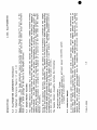
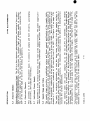
1
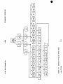
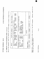
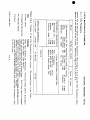
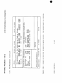
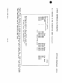
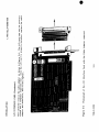
TABLE O
USER MANUAL
MODEL L11SS ELLIPSOMETER
GAERTNER SCIENTIFIC CORPORATION
71 09-C--229S
1201 West Wrightwood Avenue, Chicago, 1L
60614
S
S
1116$ ELLIPSOMETER
DESCR
TABLE OF CONTENTS
Warranty
Laser Safety
1.0 Specifications
2.0 AbbreviatIons and Symbols
3.0 Introduction
4.0 Optical System
5.0 Ellipsometer Components
5.1 Laser
5.2 Polarizer
5.3 Sample Monitor Assembly
5.4 Reference Sample
.
5.5 Analyzer
5.6 Electronic Chassis
5.7 tnstrument Power Supply
5.8 Sample Stage and Table
6.0 Determination of Psi and Delta
7.0 Standard Programs
.
.
1-1
1-2
1-3
1-5
1-6
1-6
1-8
1-8
1-8
1-9
1-9
1-11
1-11
1-11
1-11
-12
1-13
LIST OF FIGURES
1-1
1-2
TABLE
1-1
Optical System Functional Diagram
Ellipsorneter Components Identification Right-Front
1-7
1-10
Standard aid Microspot Beam Dimensions on the Sample Wafer
1-4
1109-C- 229 5
1-0
DESCRIPTION
LII6S EL
WARRANTY
ALL OF THE OPTICAL, MECHANICAL AND ELECTRICAL COMPONENTS OF THE GA
ELLIPSOMETERS, INCLUDING THE LASERS, ARE WARRANTED FOR ONE YEA
THE DATE OF DELIVERY.
ANY DEFECTS IN MATERIAL OR WORKMANSHIP
CORRECTED BY GAERTNER AT NO COST. SHIPPING CHARGES, TRAVEL AND L
COSTS INCURRED BY THE SERVICE PERSONNELARENOTCOVEREDBYTHISWAR
WARRANTIES ON DEFECTS IN MATERIAL OR WORKMANSHIP FOR COMPUTER EOU
SUPPLIED WITH THE Li i6S ELLIPSOMETER IS WARRANTED BY THE COMPUTE
FACTURER AND THEIR STANDARD WARRANTY CONDITIONS APPLY.
THE CO
MANUFACTURER WILL, AT THEIR OPTION, REPAIR OR REPLACE EQUIPMEN
PROVES DEFECTIVE DURING THE WARRANTY PERIOD. REPAIRS THAT ARE N
TATED BY THE MISUSE OF THE EQUIPMENT, INCLUDING THE USE OF SOFTW
INTERFACING NOT SUPPLIED BY GAERTNER, ARE NOT COVERED BY THIS WAR
NO OTHER WARRANTY IS EXPRESSED OR IMPLIED, INCLUDING, BUT NOT LIMI
IMPLIED WARRANTY OF MERCHANTABILITY AND SUITABILITY FOR A PAR
PURPOSE.
7109-C-229S
GAERTNER SHALL NOT BE LIABLE FOR CONSEQUENTIAL DAMAG
1-i
L116S ELLIPSOMETER
DESCR
LASER SAFETY
GOVERNING REGULATION
The Gaertner ellipsometer utilizes a helium-neon laser light source. The accessible rad
not exceed one milliwatt and, therefore, Is classified as a Class II laser product
by Radiation Performance Standards 21CFR, Subchapter J Federal Register, Volume 10 #1
1975. Appropriate WARNING and Conformance labels are affixed to the ellipsometer to al
nel of the presence of laser radiation during operation.
WARNING
Logotype
APE R TLJR E
Label
Attached to the polarizer arm and
reads: LASER RADIATION. DO NOT
STARE INTO BEAM.
Attached to the exit aperture o
polarizer module and reads:
AVOID EXPOSURE. LASER RADIA
IS EMITTED FROM THIS APERTU
CAUTION
USER fla&ou
00 ICT STARE 1470 BEAu
çAVOID EXPO$URI!IJ
HELIUM-NIONItm*
CLASS I LAIU PR0uCT
CERTIFICATION
Lthe I
Not Shown
CAUTI ON
Attached to the left front face of
the vertical plate and reads:
THIS LASER COMPLIES WITH DHEW/
CDRH
RADIATION
PERFORMANCE
STANDARDS 2ICFR SUBCHAPTER J.
71 09-C-229S
Use of controls or adjustment
performance of procedures other
those specified herein may resu
hazardous radiation exposure.
1-2
DESCRIPTION
1.0
1116S E
SPECIFICATIONS
Net Weight approx.
Shipping Weight
30 kg 65 Ibs
#3 kg 95 Ibs
Dimensions approx.
Height
Width
Depth
Film Thickness
Range
0 to 6
0 to 6
#5.7 cm
83.8 cm
Accuracy
±3 Angs
38.0 cm
Repeatability
±1 Angs
Refractive Index
±0.005*
Laser Light Source
632.8 nm Helium-Neon Red
than
1
less
mW
accessible radiation
Line Voltage
500 and 70° are used the
Incidence Angles
Detented
most.
Beam Diameter
Standard 1 mm**
1.0 x 1.6 mm at 500
1.0 x 3.0 mm at 70°
Polarizer Drum
360° graduated at 10 intervals
with 10-part venier 0° to 1°
Sample Size
Up to 150 mm 5.9" diameter
and 10 mm thick
Method of
Measurement
Four detector-voltages are
used to determine state-ofpolarization of light of
reflected beam. The surface
parameters Psi and Delta, and
hence film thickness and index
of refraction, are calculated.
7109-C-229S
115V ac
boy ac
ac or 2
See the next page.
Standard
Program
See Se
manual.
Optional
Programs
See Se
manual.
*Over most of the mea
**Sce the next page for
ted angles. There is a
is only for adjustments
1-3
11165 ELLIPSOMETER
1.0
DESC
SPECIFICTIONS Continued
This ellipsometer has the detented angles of incidence in the table below for measuremen
There are also detents for 900, but this angle is only for adjustments.
$
Standard
Beam on Sample
Microspots*
Ream on Sample
300
1 mm x 1.15 mm
15 pm x 17.2 pm
450
1 mm x 1.41 mm
15 pm x 21.1 pm
50°
1 mm x 1.55 mm
15 pm x 23.2 pm
55°
1 mm x 1.74 mm
15 pm x 26.0 pm
60°
1 mm x 2.00 mm
15 pm x 30.0 pm
65°
1 mm x 2.37 mm
15 pm x 35.5 pm
70°
1 mm x 2.92 mm
15 pm x 43.8 pm
750
1 mm x 3.86 mm
15 pm x 57.9 pm
80°
1 mm x 5.76 mm
15 pm x 86.3 pm
*The Microspot Optics are optional components for
the polarizer and analyzer arms.
See "Optional
Components", section 6.
Table 1-1
Standard and Microspot beam dimensions on the sample wafer.
7109-C-229S
1-4
DESCRIPTION
2.0
ABBREVIATIONS AND SYMBOLS
Nf
Real value of refractive index
for film being measured
Kf
Extinction value of refractive
index for film being measured
L116S
ADJ
Adjust
PD
Ph
AMPL
Amplifier
PFLG
Pe
AS
Autoset
PIG
Pa
A/AUTO Automatic
PWR
Po
N
Real value of refractive index
for substrate
cm
Centimeter
RECT
Re
K5
Extinction value of refractive
index for substrate
CTL
Control
REF
Re
PHI Angle of incidence
DET
Detector
SM
St
`v
PSI Amplitude ratio as
determined by measurement
M/MAN
Manual
SOP
St
mm
Millimeter
SPLY
Su
A
DELTA Phase difference as
determined by measurement
nm
Nanometer
STU
St
PCTL
Peripheral Control
SW
Sw
W/O
Wi
`
AID
Analog-to-digital
1109-C--229S
1-5
11165 ELLIPSOMETER
DESC
3.0 INTRODUCTION
This section describes the components of this ellipsometer and shows how the ellipsomet
the effect of reflection on the polarization of the laser light striking the surface of
such as bare substrates, to acquire measurement data identifying properties critical
control.
Interpretation of the data yields the optical constants of the material
material surface is film-covered, the thickness and optical constants of the film. On
by the user, analysis and measurement are automatic, utilizing a programmed, desktop comp
faced with the ellipsometer. Parameters are entered by the user via the computer keyboar
requiring operator/computer interaction and actual measurement data are displayed on t
screen.
Measurement data may be printed for a permanent record. Optional equipmen
Optional Components section.
4.0
OPTICAL SYSTEM Reference Figure 1-1
Ellipsometric measurements involve illuminating the surface of a sample wafer with mon
light of a known wavelength and polarization and then anatyzing. the polarization of th
lIght.
The light is projected along a fixed path or angle of incidence .
This e
has provisions for precise, pin-located settings of the angle of incidence at 300, 45°
600, 65°, 70°, 75°, 800 or 900.
For measurement purposes, the angle of reflection is always set at the same angle as t
incidence. Since the two angles are always equal, It is usual to refer to both angles a
Incidence.
With the angles properly set, their respective optical axes intersect t
center line of the plane of incidence at the same point
The spjjj*Ie Is raised or
that the intersection of the incidence ai reflective optical axes occurs on the samples
that tThe sample surface is normal to the vertical centerline of the plane of Incide
ensures that tiw light from the polarizer aperture is reflected from the sample surfa
analyzer apertui'e.
7109-C-229S
1-6
DESPCRIPTION
L116S
633 nm
RED LASER
POLARIZER ARM
ATTENUATOR
C
POLARIZED LIGHT
ANALYZER ARM
POLARIZER DRUM
MANUALLY TURNED
I
DEPOLARI ZER
POLARIZER
PRISM
//
ANGLE OF INCIDENCE
LI NEARLY
POLARIZED LIGHT
S
ELLI PTI
POLARI
SAMPLE WAFER ON THE TABLE
Figure 1-1
7109-C-2295
This is the Optical System Functional Diagram for a single-waveleng
1-7
DESC
L116S ELLIPSOMETER
4.0
OPTICAL SYSTEM Continued
A low-power Class II laser-light source is employed; a helium-neon laser having a beam
of 632.8 nm.
The 632.8 nm red laser is in the line of the optical axis, and the b
through a polarizer prism. In passing through this prism, the beam polarization Is con
circular to linear.
The reflected light, with Its polarization altered by the optical properties of the samp
tured by the Stokesmeter SM measurement head. The four detector-voltages of the Stok
then computer-analyzed and converted into a measurement of the State-of-Polarization S
of the reflected light.
5.0
ELLIPSOMETER COMPONENTS
The main components of the single-wavelength LII6S ellipsometer are shown in Figure 1
5.1
Laser Assemblies
A red laser, with a fixed wavelength of 632.8 nm, has an attenuator that reduces the las
Class II, which is for under one milliwatt. A built-in quarter-wave depolarizer in the
put produces a circular polarization of the beam.
NOTE: When the beam attenuator subsection 5.2 is pulled out, the laser beam strikes
wafer or table surface, both the polarizer and analyzer arms must he at the same angle o
Then the ellipsometer can make measurements and will be safe to work with.
5.2
PolarIzer Reference Figures 1-1 and 1-2
Polarizer Drum and Prism. The polarizer prism, mounted in the polarizer drum, is a Gla
calcite prism that converts the circularly polarized light from the laser to linear
light. Any given angle of prism orientation from 0° to 3600 can be set by adjusting t
drum.
The angle can be set to within tenths of a degree by setting a number in wh
indicated on the drum just below zero 0 on the 0-to-i vernier scale and then ali
duation on the vernier scale to one on the drum scale. For automatic measurements, the
fix the polarizer drum at exactly 200 by inserting the locking screw into the drum's det
7109-C-229S
1-8
DESCRIPTION
5.0
ELLI P SOMETER COMPONENTS Continued
5.2
Polarizer Reference Figures 1-1 and 1-2
L116S
Beam Attenuator.
The beam attenuator more correctly called a "beam blocker
polarizer module output aperture, is a manually-operated slide device to either b
beam or to allow passage of the beam to the sample surface.
5.3
Sample Monitor Assembly
The Sample Monitor Assembly has a combination tilt monitor and 39-power, sample
scope. tJsing the viewing scope function, the operator can examine the sample surfa
imperfections.
The light source for the surface illumination is built-in, origi
sample monitor assembly enclosed in a housing above the objective end of the samp
intensity of illumination is variable by the rotation of a control on the left sid
Monitor Assembly.
Using the tilt monitor function, the operator can detect an out-of-flatness conditi
surface and compensate for this condition. The amount of out-of-flatness is determi
a reflected image projected as background on 90-degree crosshairs in the eyepiece.
accomplished by tilt adjustment of the sample table in X and V planes. The tilt ad
are just under the table. See the Operation section.
The Sample Monitor Assembly includes the following:
* Emission indicator
* Electrical Control Group:
* Key-operated ellipsometer and laser power ON/OFF switch
* Sample illumination control
5.4
Reference Sample
A silicon substrate wafer reference sample with a single-layer silicon oxide fi
Initially, the sample sh
about 780A or 7Bnm is supplied with the ellipsometer.
obtain sample measurements in the process of instrument familiarization. Periodic
should be used to obtain measurement data for comparison with previous data to
ellipsometer is in proper adjustment.
7109-C-229S
1-9
DESCRIP
L116S ELLIPSOMETER
SAMPLE MONIT
A SSE MB LV
EMISSION INDICATOR
KEY-OPERATED AC
ON/OFF SWITCH
39-POWER MICROS
POLARIZER MOD
POLARIZER DRUM
BEAM ATTENUATOR
MICROSPOT
Optional
A
M
A
150mm
ROTATION
VACU
TRANSLATION STAGE
Figure 1-2
1109-C- 229 S
Front-view components of the L1I6S Ellipsometer.
1-10
DESCRIPTION
5.5
L116S E
Analyzer Module
StokesMeter Measurement Head. The SM is a four-detector-photopolarimeter consisti
larly reflecting photodetectors which intercept the incident tight at oblique ang
The electrical signals of the four detectors are computer-analyzed to determine
SOP of the incident light in terms of the Stokes parameters.
5.6
Electronic Chassis
This assembly is in the ellipsometer base; it consists of sample and hold circui
gain circuitry, and computer interfaces.
5.7
Instrument Power Supply
This assembly is in the vertical enclosure, at the rear of the support frame. The p
vides the conversion of various line voltages, compensator control and laser drive
5.8
Sample Stage and Table
The sample stage provides a combination rotary and linear manual positioning of t
allowing measurement at any point on the sample surface. This is achieved by line
the N- X direction from center and rotation from 00 to 3600. The linear scale is
1 mm increments, numbered at 10 mm intervals from 0 to 75 mm full scale. The rot
duated in 10 increments, numbered at 100 intervals from 00 to 3600. See Figure 1
The table is vertically adjustable, so that the laser beam reflected from the s
maximized when entering the analyzer aperture.
The vertical position is adjust
knurled knob on the support structure. A clockwise rotation raises the table.
secures the vertical adjustment.
The standard table
up to one 1 degree
Gaertner just before
Assembly page 1-9.
An attachment for the
will accept samples up to 150 mm 5.9" in diameter,
in both X and V planes from the predetermined level positi
the shipment of the ellipsometer. See the description of th
A fine-motion vertical position adjustment option may be ad
vacuum pump is on the right side of the stages. See Figure
Yellow plastic locator strips are supplied for use in centering a wafer sample on t
For example:
A plastic strip can be inserted into either the 3-inch, 100 mm, 1
diameter groove in the surface of the standard table.
7109-C-229S
1-11
L116S ELLIPSOMETER
6.0
DESCR
DETERMINATION OF PSI AND DELTA
The state of polarization of the beam is determined by the relative amplitude amplitude
the relative phase shift phase difference between the two component plane waves resolv
electric field of the beam.
If the phase difference between the components is either
the beam is linearly polarized.
All other phase differences result in elliptical p
When a monochromatic beam of polarized light strikes the surface of a sample, the refle
light causes a change in the relative phases of the component plane waves and a change
of their amplitudes.
The angie DaTA 4 is defined as a phase difference.
PSI V} Is defined as the arctan
and the amplitude ratio w thus characteriz
amplitude ratio. The phase difference
tically polarized iit reflected from the sample surface. These parameters are used
the optical constants of bare surfaces or substrates and, if film covered, the th
refractive index of the film.
The refractive Index Nf is used to determine the ph
position of the film and in the case of transparent films, to establish the magnitude of
i.e., the thickness cycle before ellipsometric readings repeat.
Using measurement data obtained from the four detectors of the StokesMeter, the compute
the Stokes parameters of the reflected light.
This information, coupled with the kno
state-of-polarization, is used to determine the surface parameters, PSI and DELTA.
7109-C-229S
1-12
DESCRIPTION
7.0
L116S E
STANDARD PROGRAM DESCRIPTIONS
One standard single-point program
computer.
Sits is supplied with each ellipsometer
The Standard Single-Point Program, SiT S65+S7S+GSS+SuhS is for both L115S
ometers. There are four subprograms:
*
G5S
FILM: This subprogram determines the thickness and refractive i
layer, transparent nonabsorbing film of silicon dioxide or sili
silicon suhtrate. Data Output: Thickness, index, PSI f, DEL is,
There is a fixed index option.
*
S6S
SPECIFIC: This is similar to the Film subprogram.
luated at an incidence angle of only 700.
*
S7S
TWO ANGLE: This subprogram measures the thickness of silicon oxid
or other nonabsorbing film on silicon substrate. Two-angle measure
and 700 incidence angle.
It determines the solute thickness of
on the order or period from a matched measurement at each angl
Matched thickness values, index and a listing for each angle.
*
SubS
SUBSTRATE: This subprogram determines the optical constants of
These constants need to be known before making thin film measuremen
PSI , DEL is, real N5 and extinction K5 refractive indexes
7109-C-229S
1-13
Oxide or nitri
OPE
L116S ELLIPSOMETER
TABLE OF CONTENTS
PAGE
SUBSECTION
1.0
2-1
Premeasurement Setup
1.1
Setting the Angle of Incidence
2-1
1.2
Turn on and Warmup
2-3
1.3
Sample Table Vacuum and Alignment
2-3
2.0
2.1
3.0
3.1
2-8
Measurement Procedure
2-8
Standard and Optional Programs
2-10
User Maintenance
2-10
Cleaning
LIST OF FIGURES
2-2
2-1
L116S Eilipsometer Rear View
2-2
El I ipsometer Controls and indicators
2-4
2-3
150 mm Diameter Table
2-5
2-4
L116S Sample Stage and Table
2-5
TabieMax Display Screen
7109-C-229S
.
.
.
2-7
.
2-9
2-0
OPERATION
1.0
L1165 ELL
PREMEASIJREMENT SETUP
The premeasurement setup includes setting the polarizer aid analyzer angles of incide
on and the warmup of the ellipsometer, and initial alignment of the sample stage.
1.1
Setting the Angle of Incidence See Figure 2-i, next page
CAUTiON
Do not grasp the 632.8 nm red laser
when setting the polarizer arm.
That
may easily cause laser misalignment.
a.
Grasp the polarizer arm but never by the laser; aid at the rear of the arm, lo
screw Figure 2-i about one turn.
b.
Pull outward on spring-loaded locator pin next to the clamp screw, and move the
angle of incidence.
c.
Release the locator pin, aid move the arm slowly up or down until the pin seats in
the vertical plate. Tighten the clamp screw. This accurately sets the angle of
d.
Repeat steps a through c to set the analyzer arm angle of incidence, but do not a
to the SM StokesMeter measurement head.
NOTE: Follow steps a to d also when setting the angle of incidence at any other de
The detented angles are 3Q° and 45° to 80° in 50 steps.
There is also 90°, whic
adjustments.
See Table i-i in subsection 1.0 and Table 1-I of the Description sect
detented angles.
e.
Set the polarizer drum to 200, and secure it by inserting the locking screw Figu
hole on the side of the drum.
*See the Caution note at the top of Figure 2-i about the arms with the optional Mi
Note the statement with the asterisk just abov
at the 90° angle of incidence.
about the fact that with microspots the arms cannot be set at 90° with the larger
7109-C-229S
2-i
OPE
hiSS ELLIPSOMETER
CAUTION For 90° AngIe of lncidence*
if the 11165 has Microspot Optics, rotate the 150 mm
table so that its lifting slot is under the analyzer
Microspot.
Move the taWe to the left and down so
that neither Microspot Optic will contact the table
when both of the arms are at 90°.
SAMPLE ILLUMINATOR CONTROL
SAMPLE MONITOR,
ASSEMBLY
POLARIZER DRUM
DRUM L
STOKESMETER
632. RE
ANALYZER
ARM
ELLI P SOME TER
TIME LAG
FUSES .80A
115 or 230V
P
GPIO SOCKET, F
CABLE TO THE C
*The optional 200 mm diameter table cannot be moved out of the way of the optional Micros
Therefore the arms cannot be set at 90° with both of these options.
Figure 2-1
7109-C- 229 S
Rear and left view of the L116S Ellipsometer with the standard table.
2-2
OPERATION
1.2
LII6S
EL
Turn-on and Warmup
a.
Connect the etlipsonieter and the computer according to the Installation Section.
b.
To turn on the ellipsometer and the 632.8 nm red laser, turn the key-operated po
the Sample Monitor Assembly fully clockwise, ON Figure 2-2, next page. The Emis
tamp should illuminate. Power is applied to the laser, which should be on. A 1
mum warmup of the 632.8 nm laser Is recommended before performing ellipsometric
c.
Pull to open the beam attenuator Figure 1-2 in the Description section, and pr
following subsection.
1.3
Sample Table Vacuum and Alignment
Vacuum
In the rear part of the table are small #O-80x1/8" round head, stainles
that can be removed when a vacuum pump is connected to the ellipsometer. Remove only
will be under the wafer, but not the plug under the edge of the wafer see Figure 2
Alignment
Follow this procedure, beginning with step a.
a.
With tweezers, air wand, etc., put a reference sample or wafer with a single-layer,
film of a known thickness on the table via the insertion slot. Turn on the vacuu
connected to the table vacuum hose.
b.
Loosen the sample table clamp screw.
c.
Look into the Sample Monitor Assembly eyepiece, turn the sample illumination c
desired illumination, and then adjust the eyepiece by slightly pushing it in o
for the sharpest focus of the 90° crosshairs.
d.
Rotate either one of the Sample Monitor Control knobs in Figure 2-2 so th
reflected image of the two diagonal lines into view if not already in view, as
the eyepiece.
section 1.3 continued on page 2-6
7109-C-2295
2-3
L116S ELLIPSOMETER
OP
EYEPIECE
EMISSION
INDICATOR
ON/OFF KEY
SAMPLE
ILLUMI NATI ON
CONTROL
39-POWER MICROS
MONITOR
CONTROL
FIgure 2-2
7109-C -229 S
Ellipsometer controls and indicators on the Sample Monitor Assembly.
2-4
OPERATI ON
L116S EL
INN ER
GROOVE
150mm
GRO
12
1
CENTRAL
HOLE
3 INCH
Figure 2-3 Top view of the 150 mm approximately 6 inches diameter sample table.
in the Optional Components Section for the top view of the optional 200 mm
7109-C-229S
2-S
11165 ELLIPSOMETER
OPE
1.3 Sample Table Vacuum and Alignment continued
e.
Observe the intersection of the two wide diagonal lines and the intersection of t
crosshairs. Slowly rotate as needed the X- and Y-p?ane tilt adjustment controls Fi
to center the diagonals precisely on the crosshairs intersection. This makes corre
the sample surface out-of-flatness condition.
NOTE
The
the
may
the
width/height of the intersection of
diagonals is four arc minutes. This
be used as a reference in determining
approximate tilt adjustment needed.
f.
Using the adjustment wheel under the rear of the table and the TMAX option of th
SIPS Section 3, Standard Programs, raise or lower the table for the maximu
Figure 2-5. A clockwise rotation of the wheel raises the table.
g.
If the reading
the "s" key on
for a maximum
for a maximum
h.
Repeat steps e through g as often as necessary to fine tune the sample table adjustm
I.
Tighten the sample table clamp screw.
j.
See the standard single-point program instructions such as 511Th in the Standard
Section for the loading instructions, and use the Film program or subprogram. Proce
a measurement.
k.
Compare the thickness data measurement with previously acquired sample thickness data.
pared data should be within ±3 A ±0.3 nm.
7109-C-2295
from the previous step overshoots the graph upper limit, or is too
the computer keyboard to change sensitivity. Then readjust the tab
reading. Repeat the adjustment of the drum and the table vertically,
reading.
2-6
L1165 ELL
OPERATI ON
VERTICAL POSITION ADJUST
TILT ADJ
tx-PLAN
VERTICAL ADJUSTMENT
CLAM P
TILT A
V-PLA
ROTATI ON
CONTROL
X-TRANSLATION
CLAMP
STAGE
Figure 2-4
7109-C--229S
i-
X TRANSLATION CONTROL
L11GC Sample Stage and TnIe.
2-7
OPE
L116S ELLIPSOMETER
2.0
MEASUREMENT PROCEDURE
Place the sample wafer on the sample table, load the program software into the computer
tiate the measurements.
Once the measurements are started, press the keys as the
instructions request, then measurements are automatic.
Some measurements can be made after a 15-minute ellipsorneter warmup, the stability of
improves after a few hours, which is better for important measurements. If the ellipso
use several times a day, the laser should operate continuously.
WARNING
To avoid the hazard of laser beam disper
sion, the beam attenuator must be closed
while you adjust the polarizer or ana
lyzer arm, or when the two arms are not
at the same angle of incidence.
2. 1 Standard and Optional Programs
Valid measurements are dependent upon the selection of a program applicable to the sa
measured, and correct Interaction by the user with the computer. The standard program
with the ellipsometer are in the Standard Programs section. The optional programs availa
cial order are identified in the Optional Programs section, first page.
7109-C-229S
2-8
OPERATION
L116S ELL
TABLE ADJUSTMENT
1.
2.
ic
6-
Adjust tilt of table
Adjust table height
for maximum gain
The line marker on the right indicat
the maximum gain.
For new sample, press exit and
reenter TMAX.
1
Press s to change sensitivity.
Use only near point of maximum gain
3-.-.
Press eto exit and autorange.
21-
0-
FIgure 2-5
7109-C-229S
Computer screen displaying the photodetector output vertically.
2-9
L116S ELLIPSOMETER
3.0
OPER
USER MAINTENANCE
These maintenance instructions are operator-level procedures for routine servicing. See t
Section regarding trouble analysis, adjustment, and replacement qualified service perso
of defective components. Instructions are not included for the replacement of any laser
izer/analyzer optical or precision electro-mechanical components.
Contact Gaertner
Corporation for the repair or replacement of these items.
3.1
CleanIng
Interior cleaning of the ellipsometer i.e., the four detector measurement head, monito
and instrument power supply should not be needed. These units are designed to keep for
out. When not being used, the ellipsometer should be enclosed by the dust cover suppli
instrument.
Exposed optical surfaces may be cleaned with a camel-hair brush or
compressed air not to exceed 5 PSI. All other external surfaces may be wiped clean us
lint-free cloth, If a solvent is needed, a cloth dampened with wood or isopropyl alcohol
mended.
7109-C--2295
2-10
L116S E
OPERATION
NOTES:
7109-C-229S
2-11
sm s
LI16S ELLIPSOMETER
STANDAR
TABLE OF CONTENTS
PAGE
SIJBSECTI ON
1.0 Introduction and set up
1.1 Software Installation and loading
1.2
2.0
3-1
.
.
3-1
Sample stage or table alignment
Standard program S6S
+
S7S
+
G5S
3-i
+
SubS
3-2
3-3
2.1
S6S
2.2
Subssubstrate
3-7
2.3
S7S Two Angle
3-8
+
GSS Film subprogram
LIST OF FIGURES
3-1
Program menu of standard film subprogram
3-6
CHARTS
3-1 Standard program flow chart
7109-C-229S
3-10
3-0
S
S
S
STANDARD PROGRAM
SUDS
L116S ELLIPS
.
1.0
INTRODLJCT}ON AND SET tiP
Gaertner Ellipsometer program software is supplied on two types of discs for use on the IR
PS Series Computers. The prograni software for the IBM computers are as foflows:
* IBM PC and IBM PC XI Computers are supplied on discs compatible with a 360k-byte, S-i/
* The IBM PSI1 Computer is supplied on discs compatable with a 1.,4M-byte, 3_If?" driv
* The IBM PC At Computer Is supplied on discs compatible with a 1.2M-byte, 5-1/4" dri
This system is set up according to Section 5, %nstaflation.
1.1
Software Installation and Loading
See "Software Installation and Loading" in the Installation Section 5 of this manual.
1.2
The Sample Stage or Table Alignment
See "Sample Table Vacuum and Alignment" in the Operation Section 2 of this manual.
7109-C-229S
3-
LI16S ELLIPSOMETER
2.0
STANDARD PROGRAM S6S
STDS
+
S75
+
G5S
+
STAND
SubS STDS
This is a single-layer, nonabsorhing transparent film program with three subp
following line will be displayed in the lower left corner of the screen:
"SELECT KEY FROM BELOW AS DESIRED
1PRINT 2DISP"
Press Fl If the printer is connected and on and is to be used.
either Fl PRINT or F2 DISP will produce the main menu:
Otherwise, press
"SELECT KEY FROM BELOW AS DESIRED
IFILM 2SUBSTR 3TWOANG `lEND"
Press Fl FILM to select subprogram S6S
See Figure 3-1.
+
G5S, in which oxide or nitride films
Press F2 SUBSTR to select subprogram SubS, which evaluates bare substrates lik
Press F3 TWOANG to select subprogram 575, which takes measurements at both
determines the proper film thickness order.
5
Press F4 END to exit a program so that any other program on the disc or on anot
entered. Re sure to turn off the computer to change discs.
Observe the display; and press function key El, F2 or F3 corresponding to the desir
i.e., film S6S + G5S, substrate Subs, or two angle S7S.
This is the main
working with one of the three subprograms, to return the main menu to the screen,
key FlO.
7109-C-229S
3-2
STANDARD PROGRAM
2.1
565
+
11165
STD S
E
C5S Film Subprogram
When the Film subprogram is selected,
page 3-6;
*
*
*
*
*
*
these are the
"Default Values" left side o
Silicon substrate: N5=3.85; K5=-.02
Wavelength 6328A 632.8 nm
Si02 oxide film: Estimated index, N=1.46*
Mode of measurement: Measure N aid thickness
Angle of incidence: PHI7O°
Polarizer drum aigle: POL=20°
*For the silicon nitride films, the estimated index is N=2.OO.
NOTE: To change aiy parameter below, press SETUP F3
Any one of the following can be selected by using the corresponding key in the Film
bottom of Figure 3-1:
Key
Fl
F2
F3
F4
F5
F6
Fl
F8
F9
Function
PRINT/DISP
TMAX
SETUP
SAMPLE
OXIDE
NITRIDE
N MEAS
N FXD
LIST
FlO MENU
71 09-C-229S
This allows the choice of printed or dis
This activates the TahieMax subprogram S
This allows the setup of the input parame
The user enters identifying numbers aid/
This automatically fixes or measures inde
This is the same as the thove except for
This calculates index N aid thickness.
This fixes index N and calculates only th
This gives a listing of all of the possib
periodic multiples.
This returns the main menu to the screen
substrate or two-angle subprogram can
3-3
LI16S ELLIPSOMETER
2.1
S6S
+
STAND
STDS
G5S Film Subprogram continued
As seen on these pages, it is very often important to know the periods of the oxide
films when making measurements. The table below gives the periods for oxide and
500 and 70° with the red laser at 6328 A.
FILM
Nf
50°
70°
OXIDE
1.46
2545
2832
NITRIDE
2.00
1713
1792
For very thin films or films close to a periodic multiple, the sensitivity of the ind
is very poor; therefore, accurate thickness measurements can be obtained only by fix
the index N and then calculating the thickness. The two-angle subprogram S7S fi
thickness of thick films, based on the order or period from matched measurements
The SETUP key F3 allows entry of substrate values, fixing or measuring of index
value of index N, angle of incidence PHI, and expected film thickness. Default
above parameters will be displayed. Pressing Enter with no entry produces defaults
Otherwise, other desired values parameters may be entered. Press Enter after
The SAMPLE key F4 allows the user to assign identification letters and/or number
If the OXIDE key FS is selected for oxide films, the program automatically dete
the index N should be fixed or measured. The same is true for nitride films if t
F6 is selected.
Hence, for either oxide or nitride film on a silicon substrate
incidence, the above keys are recommended.
7109-C-229S
3-4
STANDARD PROGRAM
2.1
S6S
+
L116S
STDS
E
G5S Film Subprogram continued
NMEAS F7 and NFXD F8: The automatic fixing or measuring of the index N can
using function keys Nfxd and N Meas. These keys fix the index N and measure
respectively, regardless of sensitivity considerations, although sometimes answers ma
puted.
For example:
if attempting to measure the index N of very thin films un
stroms or 10 nm it may not be possible to compute an answer. Rut, if the index N
thickness will be computed. One oxide film example is this appears in the center
while "Select optional from below" disappears:
SAMPLE :xxx
THICK:
1051
Nf
1.464
PSI:
p44.48
DEL:
79.33
The LIST key F9 gives the thickness and the eight smallest possible thicknesses
period. One example is this appears in the lower-right of Figure 3-1:
LISTING:
1051
3870
6689
PERIOD 281gM
9508 17965
12327 20784
15146 23603
One nitride film example of a display is this center of Figure 3-1:
SAMPLE :nnn
THICK:
2614
PSI:
15.81
Nf
1.986
DEL:
106.07
The LIST key F9 gives lower right of the screen the thickness and the eight sma
thicknesses with a given period. One example is this:
LISTING:
264
2073
3882
7109-C-229S
PERIOD 2819fl
5691 11118
7500 12927
9309 14736
3-5
L116S ELLIPSOMETER
GAERTNER G5S
N5
K5
WL
N
PHI
POL
=
=
=
=
=
=
STDS
+
SubS
+
S6S
+
STAND
S7S AUTOMATIC ELLIPSOMETRY PROGRA
FOR IBM PC
3.850
-0.020
6328
1.460
70.00
115.00
Select Option From Below:
IPRINT 2TMAX 3SETUP 4SAMPLE 5OXIDE 6NITRIDE 7WMEAS 8NFXI 9LIST IO
Figure 3-1
7109-C-229S
Screen display with the Standard Film subprogram Program Menu at the
3-6
STANDARD PROGRAM
2.2
L1165 EL
SitS
SubS Substrate
Press F2 SUBSTR when the main menu is displayed see subsection 2.0, "Standard Prog
program SubS is selected so that the optical constants PSI, DEL, real N and extin
bare substrate can be evaluated. These constants are needed before making any film m
Pressing MENU F5 enters the main menu.
The angle of incidence
*
*
700
is selected automatically.
Verify that the polarizer dru
Angle of incidence: PU170°
Polarizer drum angle: POL=20°
Any one of the following can be selected by using the corresponding key:
Key
At $
=
FunctIon
Fl
F2
F3
F4
PRINT/DISP
TMAX
PHI
MEAS
F5
MENU
F6
F7
SAMPLE
POLRZR
700,
Allows the choice of printed or displayed
Activates the TableMax subprogram.
Allows change of angle of incidence to ot
Instructs the ellipsometer and computer to
urement with the given input parameter
Terminates the Substrate subprogram an
program to the main menu.
Allows identifying numbers and/or letters
Allows the input of the polarizer drum
mally 20° for the best overall sen
setting the polarizer drum close to
PSI, sensitivity and stability can he i
one substrate produced these measurements middle of the screen:
SAMPLE :Sss
Ns:
Ks:
3.791
7109-C-229S
-0.153
PSI:
9.99
3-7
DEL
173.21
LI16S ELLIPSOMETER
2.3
STNAD
STDS
S7S Two Angle
The ellipsometric thickness measurement of transparent films is a periodic functio
only one angle of incidence, the expected thickness of the film has to be known w
For 5102, a period Is 2832A 283.2 nm at a 70° angle of incidence. If the thickness
this accuracy, then measurements at two angles of incidence are needed to find
thickness.
Press F3 TWOANG in the main menu to select subprogram S7S, which takes measurem
and 70° for the most accurate film thickness measurements. A sample serial number
can be typed in and press Enter.
Then sele
Just press Enter for no number.
Nitride F2, or Nf F3.
The Two Angle program requires the cooperation of the user in changing the angle o
taking measurements at 700 and 50° angles of incidence on Oxide or Nitride films
strates, a-id determines the actual thickness of films. The thickness does not ha
within a period; however, minimum and maximum possible thicknesses, such as 0 and 3
entered.
Following is an example of a nitride film display, as it appears in the
screen:
SAMPLE :nnn
PHI=70
Nf FXD: 2.000
MATCHED THlCKNESS
265
1PRINT
2TMAX
7109-C--229S
3OXIDE
4NITRIDE
PHI=50
Nf FXD: 2.000
268
5Nf?
6SAMPLE
3-8
7LIST
8PSIDEL
9MENU
STANDARD PROGRAM
2.3
L1165 EL
STDS
575 Two Angie continued
The LISTING key F7 gives all of the possible thicknesses [within the minimum 0
20000 enteredj for 700 and 500 from which the actual thickness is matched. Piffe
values can be selected; a listing will appear on the right side of the screen.
F
listing obtained using the above minimum and maximum:
THICKNESS LISTING:
P1-11=70
265
2057
38149
5641
7433
9225
11017
12809
114601
16393
18185
19977
P1-11=50
268
1981
3694
5407
7120
8833
10546
12259
13972
15685
17398
19111
For films, of thicknesses less than 400A or within 400A of a periodic multiple,
be fixed at 1.46 for oxides and 2.00 for nitrides.
Any other default index may
prompted.
7109-C-229S
1-9
____
____
L116S ELLIPSOMETER
STAN
STD S
I
Fl
Print
P3
Displsy
I
I
I
I
I
I
F,
F
I
I
HI
I
I
I
I
a
ogit.
L5515 jJFs
JJ
F21kS"I
slUr, I
TUs.
Chart 3-1
I
I
Fill
I
Nuirld.jJ NUns
Full
j[_NIFxd
Standard Program Flow Chart
7109-C-229S
I
I
H
3-10
Jj
List
I
lipi. I
Menu
STANDARD PROGRAM
sits
NOTES:
7109-C-229S
3-11
L1165
S
S
S
OPTIONAL
1116$ ELLIPSOMETER
SINGLE-POINT MEASUREMENTS
TABLE OF CONTENTS
SECTI ONS
G C4 S
Single-layer nonabsorbing with Time Option
GC6S
Single-layer absorbing
GCOS
Two-layer nonabsorbing
GC8S4
Four-layer nonabsorbing
GC9S
Two-layer absorbing
GC9S3
Three-layer absorbing
GC1OS
Two-angle, two-layer absorbing
SC 115
Polysilicon on Oxide/Nitride on Silicon
SC12S
Oxide on Polysilicon on Oxide/Nitride on Silicon
PDS
Psi and delta only
S TD S #
R5-232 STDS# and Optional Programs
.
INFORMATION ON THE ABOVE OPTIONAL PROGRAMS
IS AVAILABLE THROUGH GAERTNER SCIENTIFIC CORPORATION
71 09-C-229S
4-0
S
.
.
L11SC/D WAFERSKAN ELLIPSOMETER
OPTIONAL PROGRA
TABLE OF CONTENTS
SECTION
1.0
Introduction
2.0
Set Up
3.0
Starting the Program
14.0
5.0
Working in the Engineering Mode
4.1 Setting Parameters
4.1.1 Film Parameters
4.2 Setup Files
Working in the Production Mode
LIST OF FIGURES
Figure
Figure
Figure
Figure
Figure
Figure
Figure
Figure
Figure
4-6.1
4-6.2
4-6.3
4-6.4
4-6.5
4-6.6
4-6.7
4-6.8
4-6.9
Option Portion of the WS11A Main Menu Screen
Typical Parameter Box Section of Engineering Mode Screen
Typical Engineering Mode Screen of WSI1A Program
Example of Parameters Option Screen
Example of Film Parameters Option Screen
Example of Film Parameters Option Screen
Example of Engineering Mode SETUP Files List Screen
Example of SETUP Files List in Production Mode
.
Example of Attempt to Retrieve Out-of-Mode File
.
.
LIST OF CHARTS
Chart 14-6.1
7 109-C-230F-Rev
WS11A Modification of WS Flow Chart
4-6.0
.
.
OPTIONAL PROGRAMS
1.0
-
L1ISC/D WAFERSKAN E
WS1IA
INTRODUCTION
The WS1IA Optional Program is a specific two-layer, waferskan measurement, absorbi
for use with the Gaertner L115C/D Waferskan Ellipsometer and an IBM PC/PS Computer
calculates thickness and absorption of a polysilicon film on a layer of oxide or
silicon substrate. It is a modified version of the WS Standard Waferskan Program.
This instruction describes the unique features and functions of the WS1IA Optional
work effectively in the program a thorough familiarity with the WS Standard Wafers
recommended. While the WS11A optional instruction may describe, in some cases, a p
the two operations are similar, in some other instances, where the two programs ar
reference is made because the point has been discussed in detail in the standard waf
instruction.
2.0
SET UP
Refer to the INSTALLATION Section and the "Program Software" Instructions #710
STANDARD PROGRAMS Section for information regarding setup, software installati
and table vacuum and alignment.
3.0
STARTING THE PROGRAM
Several seconds after the WS11A program is selected from the waferskan system
Figure 4-6.1, the Main Menu appears.
Select Option:
1: Production
Figure 4-6.1
2: Engineering
1O:ENI
Option portion of the WS11A Main Menu screen.
7109-C-230F-Rev.
4-6.1
L1TSC/D WAFERSKAN ELLIPSOMETER
4.0
OPTIONAL PROGR
WORKING IN THE ENGINEERING MODE
To start the Engineering Mode press the F2:Engineering key in the Main Menu.
Figure 14-6.2 pears.
WSI1A:
SETUP file: Default
Solve:
Kf index
Film parameters for the Polysilicon on Oxide or Nitride:
Poly
-Thick exp: ?
Nf fxd: 4.060
Kf exp:
Oxide
-Thick2fxd: 0
Nf2fxd: 1.460
Kf2fxd:
Substrate
-Ns: 3.850
Ks: -0.020
INSTRUMENT PARAMETERS
Wavelength A
Phi
Ambient
Polarizer Angle
: 6328
: 70.00
: 1.000
: 45.00
A scre
-0.049
-0.000
5-Point WAFERSKAN PARAMETERS
Plot: Thickness
Wafer diameter-mm: 150.00
Outer meas dia-mm: 132.00
Measure center point: Yes
STATUS
Figure 4-6.2
Typical parameter box section of the Engineering Mode screen.
Enter these parameter values in the following order:
1.
2.
3.
4.
Poly thickness
Poly Nffxd
Poly Kfexp
Oxide: Thick2fxd
7 109-C-230F-Rev
expected thickness entry is required in the initi
default value=4.060 at 6328A.
default value=-0.049 at 6328A.
entry is required in the initial film setup.
4-6.2
OPTIONAL PROGRAMS
4.0
-
WS11A
L11SC/D WAFERSKAN E
WORKING IN THE ENGINEERING MODE continued
When all the parameter values are entered, the screen display is similar to Figure
WS11A:
SETUP file: Default
Solve:
Kf index
Film parameters for the Polysilicon on Oxide or Nitride:
Poly
-Thick exp: 500
Nf fxd: 4.060
Kf exp:
Oxide
-Thick2fxd: 100
Nf2fxd: 1.460
Kf2fxd:
Substrate
-Ns: 3.850
Ks: -0.020
INSTRUMENT PARAMETERS
Wavelength A
Phi
Ambient
Polarizer Angle
: 6328
: 70.00
: 1.000
: 45.00
-0.049
-0.000
5-Point WAFERSKAN PARAMETERS
Plot: Thickness
Wafer diameter-mm: 150.00
Outer meas dia-mm: 132.00
Measure center point: Yes
STATUS
Select Option:
1:Pmtrs
2;Exe
3:SetupFiles
4:Sample
5:PrtON
8
Figure 4-6.3
Typical Engineering Mode screen of the WS11A program.
Oxide layer have been entered.
7109-C-230F-Rev.
4-6.3
10:Exit
Arbitrary
L115C/D WAFERSKAN ELLIPSOMETER
4.0
OPTIONAL PROGR
WORKING IN THE ENGINEERING MODE continued
Choose any option of the Engineering Mode in any order as needed:
Key
Function
Fl:Pmtrs
Set or change the values of the parameters section 11.1.
F2:Exe
Execute a measurement with the current status of the parameters be
"active set of parameters". A menu choice is available between
and wafer scan measurement section 1.2 of the WS instructions
F3:SetupFiles
Save an active set of parameters or delete an existing set secti
F4:Sample
Assign a sample ID to a graphic screen.
F5:PrtON/OFF
This is a toggle function.
Press:
Menu Display:
F1O:Exit
4.1
F5:PrtON
F5:PrtOFF
F5:PrtOFF
F5:PrtON
Printer Response:
a. Automatically print the measure
each measurement during the Execu
b. When the current parameters a
press F5:PrtON, choose the correspo
from the F1:Pmtrs menu and press
print the parameters.
The printer is deactivated.
Terminate the Engineering Mode and return the WS11A Main Menu t
Setting Parameters
Use the F1:Pmtrs key to review and settchange the sample parameter values. The Eng
menu is replaced by the Parameters menu when the Fl:Pmtrs key is pressed Figure
7109-C-230F-Rev.
4-6.4
OPTIONAL PROGRAMS
4.1
-
WS11A
L11SC/D WAFERSKAN E
SettIng Parameters continued
WS11A:
*SETUP file; TEST3
Solve:
Kf index
Film parameters for the Polysilicon on Oxide or Nitride:
Poly
-Thick exp: 500
Nf fxd: 4.060
Kf exp:
Oxide
-Thick2fxd: 100
Nf2fxd: 1.460
Kf2fxd:
Substrate
-Ns: 3.850
Ks: -0.020
INSTRUMENT PARAMETERS
6328
Wavelength A
Phi
: 70.00
Ambient
: 1.000
Polarizer Angle : 45.00
-0.049
-0.000
S-Point WAFERSKAN PARAMETERS
Plot: Thickness
Wafer diameter-mm: 150.00
Outer meas dia-mm: 132.00
Measure center point: Yes
STATUS
Select Parameter Option:
1:Film
Figure 4-6.4
4:Waferskan
10:Exit
Example of the Parameters option screen.
Function
See section 4.1.1.
F1:Film
Set the Film parameters.
F4:Waferskan
Set the parameters for a 5-Point, 9-Point, X-V GRID, USER-Mo
Waferskan. See section 1.1.3 of the WS instructions.
F10:Exit
Terminate the Parameters option and return the Engineering men
7109-C-230F-Rev.
4-6.5
LIISCID WAFERSKAN ELLIPSOMETER
4.1.1
OPTIONAL PROGR
Film Parameters
Choose the F1:Fiim option from the Parameters Menu Figure 4-6.14 and the Film Para
appears at the bottom of the screen. Reference Figures 4-6.5 and 4-6.6.
*SETtJP file: TEST3
WSI1A:
Solve:
Kf index
Film parameters for the Polysilicon on Oxide or Nitride:
Poly
-Thick exp: 500
Nf fxd: 4.060
Kf exp:
Oxide
-Thicklfxd: 100
Kf2fxd:
Nf2fxd: 1.1460
Substrate
-Ns: 3.850
Ks: -0.020
INSTRUMENT PARAMETERS
Wavelength A
Phi
Ambient
Polarizer Angle
: 6328
: 70.00
: 1.000
: 45.00
-0.049
-0.000
5-Point WAFERSKAN PARAMETERS
Plot: Thickness
Wafer diameter-mm: 150.00
Outer meas dia-mm: 132.00
Measure center point: Yes
STATLJ S
Select film parameters:
2:Poly Layer
FIgure 4-6.5
3:Oxide Thk
4: +Nitride
Example of the Film Parameters option screen.
10:Fxit
The second layer is an
Function
F2:Poly Layer
F 3: OxideThk / Nitride Thk
F't: -*Nitride/-,Oxide
F 10: Exit
7109-C-230F-Rev
Enter new values for thickness. refractive index and/o
of the Poly Layer Top Layer.
Enter new thickness for the second layer. The F3 key lab
automatically when the FIt key is toggled.
Toggle function: Change the second layer from Oxide to N
-*Nitride or from Nitride to Oxide press ÷Oxide.
Terminate the Film Parameters option and return the Par
to the screen.
4-6.6
OPTIONAL PROGRAMS
4.1.1
-
WS11A
LI15C/D WAFERSKAN E
FIlm Parameters continued
*SETUP file: TEST3
WS1IA:
Solve:
Kf index
Film parameters for the Polysilicon on Oxide or Nitride:
Poly
-Thick exp: 500
NI fxd: 4.060
Kf exp:
Nitride
Kf2fxd:
-Thick2fxd: 100
Nf2fxd: 2.000
Substrate
--Ns: 3.850
Ks: -0.020
INSTRUMENT PARAMETERS
Wavelength A
Phi
Ambient
Polarizer Angle
: 6328
: 70.00
: 1.000
: 45.00
-0.0149
-0.000
5-Point WAFERSKAN PARAMETERS
Plot: Thickness
Wafer diameter-mm: 150.00
Outer meas dia-mm: 132.00
Measure center point: Yes
STATUS
Select film parameters:
2:Poly Layer
Figure 4-6.6
3:Nitride Thk
4: -`Oxide
Example of the Film Parameters option screen.
7109-C-230F-Rev.
4-6.7
10:Exit
The second layer is a
L1I5C/D WAFERSKAN ELLIPSOMETER
4.2
OPTIONAL PROGR
Setup Flies
The active set of parameters can be stored into a SETUP File and used later in th
Mode.
Press the F3:SetupFiles key in the Engineering Menu Figure 4-6.3 to displa
files list.
Disc Drive C:OOTTT
Files currently on disc
File name
Date
Store Option
REDI
05-22-1995
SETUP DATA
:
RED2
05-22-1995
SETUP DATA
:
TEST1
12-06-1995
SETUP DATA
:
TEST2
12-06-1995
SETUP DATA
TFST3
12-06-1995
SETUP DATA
:
<<cc
>>>>
End of File List
5 files
Film Mode
WS
WS
WS1IA
WS1IA
WSIIA
Select option:
1:Store
FIgure 4-6.7
3:Delete
7:Up
8:Down
1O:Exit
Example of an Engineering Mode SETUP files list screen DIRECTRY.OO
Key
Function
F1:Store
Store the active set of parameters to an external SETUP file
Only W511A film mode flies can be created and then used in t
Mode with this WSI1A optional program.
Delete y existing SETUP file in the list WS, WSI1A
optional program film mode, i.e., WS6A, WS8A, etc..
Roll the screen up. The number of files in the list appears
Screen capacity is 14 files,
If more files
right corner.
the legend "" * more * **" appears at bottom of the page.
Roll the screen down.
Terminate the SETUP Files program and return the Engineeri
to the screen.
F3:Delete
F7:Up
F8:Down
F10:Exit
7109-C-230F-Rev.
4-6.8
OPTIONAL PROGRAMS
5.0
-
WS11A
L11SC/D WAFERSKAN E
WORKING IN THE PRODUCTION MODE
Press the F1:Production key in the WS11A Main Menu Figure `t-6.1 to begin
Production Mode. The Production Mode pathway is the same as the WS Standard Wafe
pathway.
Disc Drive C:OOTTT
Files currently on disc
File name
RED1
:
RED2
:
TEST1
TEST2
:
TEST3
5 files
Date
Store Option
05-22-1995
SETUP DATA
05-22-1995
SETUP DATA
SETUP DATA
12-06-1995
12-06-1995
SETUP DATA
12-06-1995
SETUP DATA
<<<<
>>>>
End of File List
Film Mode
wS
wS
WS11A
WS11A
WS11A
Select one option:
1:Retrieve file
7:Up
8:Down
10:Exit
Figure 4-6.8 Example of a SETUP file list in the Production Mode.
WS11A Production Mode
It is the firs
Key
Function
F1:Retrieve file
Retrieve a WS11A SETUP file for execution of a measur
file created in this WS11A optional program can be retrie
Roll the screen up.
Screen capacity is 14 files. The
files in the list is shown in the upper right corner.
Roll the screen down.
Terminate the Production Mode and return the WSIIA Ma
screen.
F7:Up
F8:Down
FlO: Exit
7109-C-230F-Rev
4-6.9
LJTSC/D WAFERSKAN ELLIPSOMETER
5.0
OPTIONAL PROGR
WORKING IN THE PRODUCTION MODE continued
Disc Drive C:'i.,OOTTT
Files currently on disc
File name
RED1
RED2
TEST1
TEST2
TEST3
S files
Date
Store Option
05-22-1995
SETUP DATA
05-22-1995
SETUP DATA
12-06-1995
SETUP DATA
12-06-1995
SETUP DATA
12-06-1995
SETUP DATA
<<<<
>>>>
End of File List
Film Mode
WS
WS
WS11A
WS1JA
WS11A
Filename to retrieve for a WS11A only? RED1
Not a WS1IA file ! <ENTER> key & retry.
To Exit, press just <ENTER> key.
RED1 is a
FIgure 4-6.9
Example of an attempt to retrieve an out-of-mode file.
Only
file and cannot be retrieved while working in the WS11A optional program.
TEST2 and TEST3 can be retrieved at this time.
7109-C-230F-Rev.
4-6.10
OPTIONAL PROGRAMS
-
L115C/D WAFERSKAN ELL
WS11A
Parameters Menu
Continued From
Chart 3-1.1
I
I
I
I
Continue
F2
Poly
Layer
F3
Oxidemk/
NitrideThk
Fit
.Nitride/
`Oxide
rio
Exit
Chart 3-1.2
Chart 4-6.1
WS11A modification of
7109-C-230F-Rev.
the WS flow chart.
With
L1I6S ELLIPSOMETER
INSTALLATION/IBM CO
TABLE OF CONTENTS
Unpacking
5-1
Inspection
5-2
Location Considerations
5-2
Interconnections
Ellipsometer and Computer
Computer & Printer
5-2
5-2
5-4
Software Installation and Loading
5-4
Computer Circuit Board Installation
5-8
LIST OF FIGURES
5-1
5-2
5-3
5-4
5-5
5-6
AC Power Plugs
L1I6S System Interconnection Diagram
Ellipsometer Left and Rear View
IBM PS/i Computer and Connections
AID Interface Card
A/D Interface with Cable Adapter removed
7 i09-C-229S
5-0
5-3
5-5
5-6
5-7
5-8
5-9
INSTALLATION
Li 16
The Gaertner ellipsometer is shipped fully assembled, along with needed items, in
crate. The applicable items are as follows:
*
*
.
*
*
*
Ellipsometer User's Manual
Ellipsometer/Computer Interface Cable
Analog to Digital Converter Card
Software Programs
Silicon Wafer Reference Sample
Dust Cover
*This component is supplied to customers with their own computers. But c
shipped with the ellipsometer will have the AID card already installed.
UNPACK I NC
Remove the protective wrapping from the ellipsometer. Remove the lag bolts that
down clamps to base of the ellipsometer. Remove the hold-down clamps. This allo
the ellipsometer from the shipping crate base platform. DO NOT apply any pressu
NOTE
Store the shipping platform, shipping crate parts and protecttive wrapping in case of a reshipment to Gaertner for repair.
WHEN PACKING THE ELLIPSOMETER FOR RESHIPMENT TO GAERTNER FOR REPAI
SOFTWARE PROGRAMS AND INTERFACE CABLES WITH AID INTERFACE CARD,
CONTACT GAERTNER FIRST.
CAUTION
In event of reshipment, care must be taken to ensure that 1
the polarizer arm is set and clamped at 500 angIe of inci
dence and 2 the analyzer arm is set and clamped at 500
angle of incidence before packing. This will prevent damage
to the helium-neon red laser assembly and analyzer module.
7109-C-229S
5-i
1116S ELLIPSOMETER
INST
INSPECTION
Thoroughly inspect the ellipsometer for shipping damage.
the carrier.
If there is damage from tra
A key should be installed in the keylock switch located on the right side of the Sam
Assembly above the sample table; it should be off. Check that good a fuse is in the el
Verify that all applicable items have been included in the shipment.
LOCATION CONSIDERATIONS
The Gaertner ellipsometer is designed for use in either a production or laboratory fa
relatively constant room temperature and a relatively dry, dust-free atmosphere. The
requires a clean, level solid work surface sufficient to also accommodate the interface
The input ac line voltage must be free of large transients having harmonics in the range
frequencies to several megahertz. Do not obstruct the ventilation holes on any of the
INTERCONNECTIONS
DO NOT plug or unplug any component into or from ac power or make connections to othe
with its power ON/OFF switch ON!
The ac line cable for the ellipsometer is on the left side, near the rear of the instr
supply and is labeled INPUT POWER. The ac line cable for the helium-cadmium laser
at the rear of the laser power supply.
CAUTION
Verify that the power switches on all of the components are
OFF before connecting or disconnecting the interface cabling.
An interconnection diagram for the ellipsometer is shown in Figure 5-2.
Ellipsometer and Computer
See Figure 5-3 ellipsometer rear view, and Figure 5-4
computer.
See Figure 5-5 A/D interface card, &id Figure 5-6 A/D interface card
adapter removed.
7i09-C-229S
5-2
INSTALLATION
11165
AC POWER PLUGS
The Gaertner ellipsometer is supplied with a U.S. plug NEMA 5-15P.
the plug, the following guidelines apply:
If it is nec
NEWt liP
It nfl'.
Great Britain, Cyprus, Nigeria,
Rhodesia and Singapore
8
Underwriter's Lab
for the United Stat
Japan, Mexico, Phi
Ti awan
110* SiR
Australia and New Zealand
UL approved for th
stv liii
tEE lull
Eastern and Western Europe,
Saudi Arabia, and United Arab
Republic
Switzerland
Figure 5-1
NOTE: All plugs are for single-phase power and are viewed above from the co
prongs are:
*
L
=
*
N
=
Neutral or identified conductor.
*
E
=
Earth or safety ground.
7109-C- 2 29 S
Line or active conductor, also called "live" or "hot".
The insula
The insulation is white
The insulation is green.
5-3
INST
L1I6S ELLIPSOMETER
Computer aid Printer
Connect the Centronics Interface Cable 7108-E-239t to the parallel receptable on the
computer and at the connector on the printer.
See Figure 5-3 ellipsometer rear
Figure 5-4 IBM PS/I computer. Hand tighten the connector thumb screws.
SOFTWARE INSTALLATION AND LOADING
NOTE: Wherever in this instruction the prompt is to type in some specific characters,
ters are in boldface and just after "type". Type in the characters, and press Enter.
Software installation on the Customer-Suppl led Computer:
The computer will ioad DOS from the hard disc which must have at least three megaby
space, drive C.
a. * Turn on the computer, aliow it to "boot-up", and insert the program disk into driv
* The screen should show that drive C is the default by displaying, for example, th
"C:>". Type a: and press Enter to make A the default, i.e., "A:V".
* Type install aid press Enter.
disc C.
* Remove the program disc.
b.
All of the files on the program disk will then be
Go to step c. for installing any optional programs.
NOTE: The following occur during the software installation:
1 A directory is created: c:'.gsc.
2 All of the driver and executable files are copied in that directory.
3 Autoexec.bat and config.sys files on c: root directory are created.
If the
and config.sys files already exist on c: drive, it copies them to autoe
config.bak before installing new ones.
c.
OPTIONAL PROGRAM INSTALLATION: If one or more optional programs has been ord
each optional program disc into drive A. The default drive should be A. If it is not,
press Enter so that A is the default. Type Install aid press Enter. Remove the prog
7109-C-229S
5-4
______
____________________
______________
INSTALLATION
Li 16S
IBM
DISPLAY
UNIT
GPIO COMPUTER INTERF
CABLE C-10161-'ISDh
IBM PS/i
CbMPUTERCOILED
ELLIPSOMETER
LE
KEYBOARD
L116S
F
I
NEC P6200
PR? NT ER
PARALLEL CENTRONICS INTERFACE CABLE
7 108-F-239t
Figure 5-2 L116S Ellipsometer Interconnection Diagram.
with the L116S is the IBM PS/i.
7109-C-229S
s-s
The computer that Gaer
L116S ELLIPSOMETER
INSTA
RED 632.8
MICRO
ELLIPSOMETER
SLOW-BLOW
FUSE, .75A
115 or 230V
GPIO SOCKET,
CABLE TO THE
TO AN AC OUTLET
Figure 5-3 Rear and left view of the L116S Ellipsometer with the 6-inch diameter tab
632.8 nm helium-neon laser.
7 109-C-2295
5-6
L116S
INSTALLATION
LOWER
SOCKET FO
TO THE E
TO AC POWE
PARALLEL SOCKET FOR THE
CENTRON1CS INTERFACE
CABLE TO THE PRINTER
Figure 5-k
7109-C-229S
IBM PS/i
computer and its connections.
5-7
.
`1
C
V
;o.-i
>
cD;
CD
a
*1
tZ
-*i
W°
kC
,a
CD
r"
5*
0
0'
0
°fl
>
fl
`1
m'
C,
>,
r
0
t0
cow
`
.
C
0
-I
to
CD
z
-
C
...
-
n
o
Z
00
`°
rn
3
-w
CD,
n,
s
1CD
a'
50.
`r
tO
rn
r
r
.
c
-u
r
-ti
°
u,
If'
CM
V
r
-
-`-
m
-.cI
IA
u,
>
E
q
a
CD'.°
-
-
-w
03C
0
-
m
-t
D.
a_.
5D
?a
CD
CD
-ti
0,
C
CD
0
Dr
r
-
C,
0,
I
-1
-4
>
t-.
cui
0
*0
z
a
-I
a.
°*`a
-s
hiiiiIliuoivmoIw1ivflu!
-,
IMCD
`
Vc
11
ttlD
0-o
-
m
Ig*5
-
D
`<C
m
C
m
a
V
"
z
to
X
`S'?
-
>
0
-
m
5
-
CD
U'
tmu,
`r
r<
,
;
C,
tD
Oi
<U,
-n
r
or
-
to
aV
r?
V
r
Vu,
.c
3
-tic
a.
fl
V
C
c
-tim
-0
m
a
*t
o,W
?
0
V
0
3
w
.
.
r
r
In
>
-
-
CD
0
V
0.
5'_
____
_____
!`
I*
INSTALLATION
1116S EL
AID INTERFACE CARD Continued
Now carefully remove the cable adapter as shown in Figure 5-6. The A/F card may no
seated into a computer expansion slot. Once the A/fl card is properly installed, rep
adapter and stand-offs; then firmly tighten.
*
r-?,.i
u.e
*-T
rv'v" `i
-s_-
Li
I
I
- .
C-.,-.
F
*
-
-
-
p____,_..__**
-
J
-
-
C" CIT
111:1
H
-.
-
--
-.
I:,..
-4%'
-S
-
S
4
-
FIgure 5-6
7109-C-229S
Photograph of the AID Interface Card with the Cable Adapter removed.
5-9
L116S ELLIPSOMETER
OPTIONAL CO
TABLE OF CONTENTS
Page
Hand Positioning stages, L116HXY6 and L116HXY5
6-1.
Micrometer Positioning Stages, L116MXY6 and L116MXYS
6-1.
Fine Motion Height Adjustment L117FM
6-1.
Microspot Optics, L116MS
6-1.
Interface LR5232
6-1.
Video Monitor L115VM
6-1.
Wafer Handler L1I6WH
6-1.
200 mm Sample Table
6-1.
FIGURE
6-1.1
7109-C-229S
200 mm Sample Table Top View
6-1.
6-0
.
.
.
L116S ELLI
OPTIONAL COMPONENTS
HAND POSITIONING STAGES
LI16HXY6
This stage accepts 6-inch samples and enables the sample table to he move
in X,Y and 0 directions to facilitate measurement at any desired point on the sample surfac
and Y coordinates translation facilitates measurement on a rectangular or grid pattern; z
2 inch left-to-right translation X direction, 1 inch in the -Y direction from center, and
-
in the +Y direction.
If the whi
Total rotational travel 9 direction is 00 to 3600.
retainers are removed from the table, translation in the +Y direction is increased to 1 i
L116HXY5
This stage is identical to the L116HXY6 stage except that this table will allow
ments on samples 5 inches in diameter or less. The front-to-back translation Y direc
inch from the center.
-
MICROMETER POSITIONING STAGES
L116MXY6
This stage is identical to the L116HXY6 stage except micrometer thimbles are
allow fine motion translation in the X and Y directions to facilitate positioning within r
scribe lines. One division on the thimble equals 0.001 inch. This stage Is especially u
the Microspot Optics L116MS accessory.
-
L116MXYS
This stage is identical to the L116MXY6 stage except that this will allow measur
sample wafers no greater than 5 inches in diameter.
-
EINE MOTION HEIGHT ADJUSTMENT LI17FM
This feature may be added to &iy type of sample stage and consists of a rotatable incl
acting through a transfer plate and the standard height vertical position adjustment t
lower the table 0.010 inch maximum from the mid-position reference after setting the
vertical position. One half turn of the knob moves the table 0.010 inch. The knob is a
position when the center line of the reference hole on the knob is at the centerline of
clamp screw.
A clockwise rotation of the knob raises the table CC.W lowers the ta
pages 6-2.1 and 6-2.2 for detailed information.
7109-C-229S
6-1.1
L116S ELLIPSOMETER
OPTt
MICROSPOT OPTICS L116CMS Gaertner Installed
This option has a projector optic that reduces the normal 1 mm diameter beam at t
down to 0.015 mm to measure very small areas and a receiver optic for added
the table in subsection 1.0 Specifications in the "Description" Section of this u
NOTE: The table in subsection 1.0 Specifications shows the dimensions of the
sample with and without the Microspot Optics at different angles of incidence, j.
INTERFACE LRS232
This option enables the user to send or receive serial data via an interface with R
equipment such as a large-scale host computer, data terminal and modems.
I
cable, modified software and program User Instructions. Contact Gaertner for d
data communication specifications.
VIDEO MONITOR L115VM
This option allows the ease of monitoring a wafer pattern display on a CRT screen
standard viewing microscope. An MIT switch is usually mounted on the front of t
Assembly when a video monitor is included with an ellipsometer.
WAFER HANDLER L1I6WH
Model L116WH Wafer Handler permits unattended automatic measurement of up to
cassette. The randon-access indexer on the Wafer Handler is ultra clean with th
contained within the housing so that there are no moving parts near the wafer. Th
of motion of the arm is simple, clean and gentle.
200 mm 7.9 inches diameter SAMPLE TABLE
This larger table is for 3" 76 mm. 100 mm, 125 mm, 150 mm and 200 mm wafers for fi
See Figure 6-1.1 for a top view of this table.
NOTE: If an ellipsometer has a 200 mm diameter table and the Microspot Optics,
to move this table out of the two arms so that they can be set at a 900 incidence a
any instructions that call for setting the arms at 90°.
7109-C-2295
6-1.2
OPTIONAL COMPONENTS
L116S ELLI
OUTER
GROOVE
IUNER
GROOVE
126 M
FIgure 6-1.1
7 109-C-229S
ThIs Is a top view of the 200 mm 1.9 inches diameter sample table.
6-1.3
S
S
S
LII6S ELLIPSOMETER
PAGE
TABLE OF CONTENTS
1.0 TroubleAnalysis .
1.1 Measurement system
1.2 Troubleshooting
7-1
7-1
7-1
2.0 DiagnostIcs
2.1 Photodetector Zero Offset Adlustment
2.2 Automatic Amplifier Gain Check
2.3 Optical Alignment Check
7-7
7-7
7-7
7-7
LIST OF FIGURES
7-1
7-2
7-3
7-4
7-S
Measurement System Functional Diagram
L1J6S Left and Rear View
Diagnostic Program DIAG Main Menu
Test/Display A-B Board Outputs DIAG
Alignment Display D1AG
H
7-2
7-6
7-8
7-9
7-10
LIST OF TABLES
7-1
7-3
Troubleshooting Guide
7109-C-229S
7-0
SERVICE
1.0
L116S
TROUBLE ANALYSIS
Caertner ellipsometers should have long-life, trouble-free operation. In the eve
tion, symptoms are readily traceable by the use of diagnostic software and i
points.
Fault isolation
This should be done by qualified service personnel.
shooting to isolate the cause of failure only to a component or assembly readi
further fault isolation and repair or replacement.
During automatic operation,
usually shown by no measurement data, inconsistent measurements, or even operato
1.1
Measurement System
During automatic operation, the four-detector-voltages of the StokesMeter are amp
to the circuitry of the Sample and Hold Board. See Figure 7-1. Digital control p
with timing circuitry to provide a trigger for the Sample and Hold system. Thi
voltages to be sampled simultaneously.
The sampled voltage levels are adjus
Finally, the a
controlled auto-gain circuitry to fall within a lv
9V range.
converted to digital signals and are read by the AID Computer Interface Card.
-
Computer analysis of the measured data yields the desired ellipsometric measureme
1.2
Troubleshooting
Table 7-1, starting on page 7-3, lists the symptoms of malfunction, possible cause a
actions relative to fault isolation. The symptoms are listed in a sequence genera
operating procedure, i.e., premeasurement setup and measurement procedure. As
guide, the listing assumes all dc power supplies are operative and no discontinuit
NOTE
The AID Circuit Board must be initialized by the
batch file INIT.BAT. ll'4lT should he the last entry
in the AUTOEXEC.BAT file on the program disc.
7109-C-2295
7-1
L116S ELLIPSOMETER
r
SM MODULE
1
AID COMPUT
INTERFACE C
SAMPLE AND HOLD
BOARD
CO
PO
CO
PO
CO
PO
CO
PO
C
P
ZERO OFFSET
ADJUST
L
Figure 7-1
7109-C-229S
L
-j
Measurement System Functional Diagram.
7-2
L116
SERVICE
TABLE 7-1.
SYMPTOM
No power to the ellipsometer
Key switch at ON
TROUBLESHOOTING GUIDE
POSSIBLE CAUSE
No line voltage
FAULT ISOLAT
Verify that the el
cord is seated in an
Check the fuses; rep
They are .75A, slow
Emission indicator does not
illuminate at power turn-on
Lamp burned out
Replace the lamp.
still present, the
supply transformer
bly transformer may
No light is emitted from
the polarizer aperture
The Ream attenuator
is closed
Check the position o
if it is closed, PULL
Defective laser or
laser power supply
Needs the replaceme
laser or removal of
supply for repair co
7109-C-229S
7-3
LII6S ELLIPSOMETER
TABLE 7-1.
SYMPTOM
Inconsistent or
inaccurate measurenients
TROUBLESHOOTING GUIDE continued
POSSIBLE CAUSE
FAULT ISOLATION
Failure to use
TableMax program
prior to measurement
See Section 3
Upon exiting the TMax progr
the
autoranging-gain cir
activated. Hence, TMax m
whenever P, P1-U, or the
changed.
Inaccurate Polarizer
Azimuth p
Observe the Polarizer dr
Ensure that it matches tha
displayed by the computer
Inaccurate incidence
angle PHI
Ensure that the angle of
match that which is displa
computer program.
Check the
knobs.
Sample table
misalignment
7109-C-229S
7-4
Check the
TMAX.
detents
tilt
and
and
t
tab
SERVICE
L116
TABLE 7-1 *
SYMPTOM
Inconsistent or
inaccurate measurements continued
7109-C-229S
TROUBLESHOOTI NC GUIDE Continued
POSSIBLE CAUSE
FAULT ISOLAT
Photdetector darkcurrent dc offset
has changed
Dark-current may b
the diagnostic prog
section 2.
Photodiode or
circuit failure
This may he verif
the measured detect
the program DIAG.
This problem should
SERVICE PERSONNE
Optical Misalignment
Alignment may he ve
of the program DIAG
DO NOT ATTEMPT
INSTRUMENT. This
addressed by SERV
ONLY!
7-5
SE
11165 ELLIPSOMETER
CAUTION For 90° AngIe of incidence'
If the ellipsometer has Microspot Optics, turn the
table so that its notch lifting slot is under the
analyzer arm. Move the table to the left and down
so that neither Microspot Optic will touch the
table when the arms are at 990*
632.8 nmj L
ELLIPSOMETER
TIME LAG FUSES
115 or 230V1
MICROSPOT
OPTIONA
CABLE
`The optional 200 mm dia. tahle cannot be moved out of the way of the optional Microspo
Thus, the arms cannot be set at 90° with both options.
Figure 7-6
7109-C-229S
Rear and left view of the L1165 Elllpsometer.
7-6
SERVICE
2.0
L116S
DIAGNOSTICS
A diagnostic program named DIAG.EXE has been supplied with this unit. This pro
troubleshooting aid. Upon running [NAG, the menu illustrated by Figure 7-3 will
2.1
Photodetector Zero Offset Adjustment
Selection F2 of the Main Menu yields the display illustrated by Figure 7-4.
Ph
Offset may be checked by simply closing the laser shutter. All voltages should th
any voltage is non-zero, press the Fl key followed by ENTER to measure the dar
information is stored in a file named DARI<CUR.DAT.
2.2
Automatic AmplifIer Gain Check
The proper operation of the autoranging-gain circuitry can be verified by usin
option shown in Figure 7-4.
Note that the laser shutter should be open, and th
occur if the four-detector-voltage average is within the IV
9V range.
-
2.3
Optical Alignment Check
Selection of Fl of the Main Menu yields the display illustrated by Figure 7-5.
cated by the centering of the crosshairs + within the target area.
NOTE
The dark-current should be measured
subsection 2.2 prior to the use of this
option.
CAUTION
DO NOT ATTEMPT TO ADJUST THE ALIGNMENT OF THIS
INSTRUMENT.
THIS WILL CAUSE A CALIBRATION FAIL
URE. CONSULT GAERTNER ABOUT ALIGNMENT PROBLEMS.
7109-C-229S
7-7
A
L116S ELLIPSOMETER
THE STOKESMETER
*****
MAIN MENU
Fl
-
ALIGNMENT DISPLAY
F2
-
TEST AND DISPLAY A-D BOARD OUTPUTS
F3
-
EXIT THIS PROGRAM
Gaertner Scientific Corporation
Figure 7-3
7109-C-229S
Diagnostic Program Main Menu.
7-8
-
©1992 Ver. 1.0
SERVICE
L116
0.946
1.080
0.728
0.716
A-D BOARD VOLTAGE DISPLAY
-
RANGE
=
0.025
1X
0.026
-
0.0214
0.025
Fl: Measure Dark Current
Figure 7-4
7109-C-229S
F2: Range
Other Key: Oult
Test and Display A-D Board Outputs DIAG.
7-9
LI16S ELLIPSOMETER
Figure 7-5
7109-C- 22 9 S
Alignment Display DIAG
7-10
S
S
S