1
INSTRUCTIONS
FOR
L 116C ELLIPSOMETER
7109-C2290
@.De
GAERTNER SCIENTIFIC CORPORATION
3650 w. Jarvis Ave., Skokie, IL 60076 USA TEL: 847 673 5006 FAX: 847673 5009
www.GaertnerScientific.com
WARRANTY:
ALL OPTICAL AND MECHANICAL COMPONENTS OF THE L116C
ELLIPSOMETER ARE WARRANTED FOR TWO YEARS FROM DATE
OF DELIVERY. ELECTRONIC COMPONENTS, INCLUDING THE LASER,
ARE WARRANTED FOR ONE YEAR. ANY DEFECTS IN MATERIAL OR
WORKMANSHIP WILL BE CORRECTED BY GAERTNER AT NO COST,
INCLUDING SHIPPING CHARGES. TRAVEL AND LODGING COSTS
INCURRED BY SERVICE PERSONNEL ARE NOT COVERED BY THIS
WARRANTY. WARRANTY ON DEFECTS IN MATERIAL OR WORKMANSHIP
FOR COMPUTER EQUIPMENT SUPPLIED WITH THE L 116C ELLIPSOMETER
IS WARRANTED BY THE COMPUTER MANUFACTURER AND THEIR
STANDARD WARRANTY CONDITIONS APPLY. THE COMPUTER
MANUFACTURER WILL, AT THEIR OPTION, REPLACE EQUIPMENT THAT
PROVES DEFECTIVE DURING THE WARRANTY PERIOD. REPAIRS
NECESSITATED BY THE MISUSE OF THE EQUIPMENT, INCLUDING THE
USE OF SOFTWARE OR INTERFACING NOT SUPPLIED BY GAERTNER,
ARE NOT COVERED BY THIS WARRANTY. NO OTHER WARRANTY IS
EXPRESSED OR IMPLIED, INCLUDING, BUT NOT LIMITED TO, IMPLIED
WARRANTY OF MERCHANTABILITY AND SUITABILITY FOR A PARTICULAR
PURPOSE.
GAERTNER SHALL NOT BE LIABLE FOR CONSEQUENTIAL DAMAGES.
1-1
7109-C-229D
L 116C ELLIPSOMETER
DESCRIPTION
LASER SAFETY
GQVERNING REGULATION
The Gaertner L116C Ellipsometer has a helium - neon laser light source. The accessible
radiation does not exceed one milliwatt and, therefore, is classified as a Class illaser product as
defined by Radiation Performance Standards 21 CFR, Subchapter J ( Federal Register,
Volume 10 #148, July 31, 1975). Appropriate WARNING and Conformance labels are affixed
to the ellipsometer to alert personnel of the presence of laser radiation during operation.
WARNING Logotype.
APERTURE Label.
Attached to the polarizer arm
and reads: LASER RADIATION.
DO NOT STARE INTO BEAM.
Attached to the exit aperture of
the polarizer module and reads:
AVOID EXPOSURE. LASER
RADIATION IS EMITTED FROM THIS
APERTURE.
CAUTION
CERTIFICATION Label.
CAUTION
Attached to the left front face of
the vertical plate and reads:
THIS LASER COMPLIES WITH
DHEW I CDRH RADIATION
PERFORMANCE STANDARDS
21CFR SUBCHAPTER J.
Use of controls or adjustments
or performance of procedures
other than those specified herein
may result in hazardous radiation
exposure.
1-2
7109·C-2290
Ll16C ELLIPSOMETER
1.0
DESCRIPTION
SPECIFICATION
Net Weight ( approx.
Shipping Weight
30kg(6Slbs)
43 kg ( 95 Ibs )
Dimensions ( approx_ )
Height
Width
Depth
45.7 cm ( 18 inches)
83.8 cm ( 33 inches)
38.0 cm (15 inches)
Laser Light Sources
( less than 1 mW
632.8 nm Helium - Neon
Red Laser
accessible radiation)
Incidence Angles,
Pre - aligned ( detent)
50° and 700 are used the most See the next page
Beam Diameter ( std. )
1 mm
1.0x1.6mmat500
1.0 x 3.0 mm at 70'
Compensator
Quarter - wave plate; fast axis at +900 to plane of incidence
Polarizer I Analyzer
3600 graduated at 1° intervals with 10· part vernier (rp to 1°)
Sample Size
Up to 150 mm (5.9") dia. to 10 mm max thickness
Method of
Measurement
Dual mode ( with and without the compensator in the laser
light path ); the polarizer drum fixed at 45°; the rotating
analyzer samples 144 data points.
Film Thickness
Range
Accuracy
o to 60, oooA
Repeatability
± 1 Angstrom (±.1 nm
± 0.005'
Refractive Index
(0 to 6,000 nm)
± 3 Angstroms ( ± .3 nm t
t
Line Voltage
11SVac ( 50 - 60Hz) std; 100Vac, 220Vac,
230Vac or 240Vac are available
Standard Program
See Section 3 of this Manual.
Optional Programs
See Section 4 of this Manual.
* Over most of the measurement range.
7109-C-229D
1-3
DESCRIPTION
L 116C ELLIPSOMETER
1.0
SPECIFICATIONS ( Continued)
This ellipsometer has the detented angles of incidence in the table below for measurement purposes.
There are also detents for 900 , but this angle is only for adjustments.
Standard
Beam on Sample
Microspots·
Beam on Sample
30'
lmmxl.15mm
15
~m
x 17.2 ~m
45'
1 mmxl.15mm
15
~m
x 21.1
~m
50'
lmmxl.55mm
15
~m
x 23.2
~m
------------------ --------------------------------------- --------------------------------------------55'
1 mmxl.74mm
15
~m
x 26.0
~m
60'
1 mm x 2.00 mm
15
~m
x 30.0
~m
65'
1 mmx2.37 mm
15~m
x 35.5
.
~m
------------------ --------------------------------------- --------------------------------------------70'
1 mmx 2.92 mm
15~m
x 43.8
~m
75'
1 mmx3.86mm
15~m
x 57.9
~m
,
------------------ --------------------------------------- --------------------------------------------80'
*
1 mm x 5.76 mm
15~m
x 86.3
~m
The Microspot Optics are optional components for the polarizer and analyzer arms.
See the Optional Components Section.
14
7109·C·229D
l116C ELLIPSOMETER
2.0
DESCRIPTION
ABBREVIATIONS AND SYMBOLS
Nt Real value of refractive index
for film being measured
AMPl
Amplifier
PCTl Peripheral Control
AS
Autoset
PO
Photodetector
Kf Extinction value of refractive
index for film being measured
AlAUTO Automatic
PFlG Peripheral Flag
Ns Real value of refractive index
for substrate
em
Centimeter
PIO
Part of
CTl
Control
PWR
Power
DET
Detector
RECT Rectifier
EBT
Encoder - buffer turnoff
cD ( PHI) Angle of incidence
lED
Light emitting
diode
REF
IjI ( PSI ) Ampl itude ratio as
lSB
Least
significant bit
SPLY Supply
Ks Extinction value of refractive
index for substrate
determined by measurement
Reference
M I MAN Manual
STD
Standard
,., ( DELTA) Phase difference as
determined by measurement
mm
Millimeter
SW
Switch
AID Analog - to - digital
MSB
Most
significant bit
W/O
ADJ Adjust
nm
Nanometer
AEC Analyzer to Electronic
Chassis
1·5
7109·C·229D
Without
L 116C ELLIPSOMETER
3.0
DESCRIPTION
INTRODUCTION
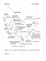
This section describes the components of the ellipsometer and shows how the ellipsometer analyzes the
Effect of reflection on the polarization of the laser light striking the surface of materials, such as bare
substrates, (as in Figure 1 - 1, next page) to acquire measurement data identifying properties critical
to quality control. Interpretation of the data yields the optical constants of the material or, if the material
surface is film - covered, the thickness and optical constants of the film. Once initiated by the user,
analysis and measurement are automatic, utilizing a programmed, desktop computer interfaced with the
ellipsometer. Parameters are entered by the user via the computer keyboard. Queries requiring
operator / computer interaction and actual measurement data are displayed on the computer screen.
Measurement data may be printed for a permanent record.
4.0
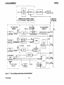
OPTICAL SYSTEM ( See Figure 1 - 1, next page)
Ellipsometric measurements involve illuminating the surface of a sample wafer with monochromatic light
of known wavelength and polarization and then analyzing the polarization state of the reflected light. The
light is projected along a fixed path or angle of incidence ( q.). The ellipsometer has pin - located
settings for the angle of incidence at 30°,45°, 50°, 55°, 60°, 65°, 70°, 75°, BOO or 90°. The 90° angle
cannot be used for measurements, only adjustments.
For measurements, the angle of reflection is always set at the same angle as the incidence angle. Since
the two angle are always equal, it is usual to refer to both angles as angles of incidence. With the angles
thus set, their respective optical axes intersect the vertical center line of the plane of incidence at the
same point. The sample table is raised or lowered so that the intersection of the incidence and reflective
optical axes is on the sample surface, and that the sample surface is normal to the vertical centerline of
the plane of inCidence. This ensures that the light from the polarizer aperture is reflected from the sample
surface into the analyzer aperture.
A low - power (Class II) laser- light source is employed; a helium - neon laser having a beam
wavelength of 632.B nm. The 632.8 nm ( red ) laser is in the line of the optical axis; and as the beam
passes through a polarizer prism, the beam polarization is converted from Circular to linear.
This constant - intensity, linearly - polarized beam is then converted to one of circular polarization when
a quarter - wave compensator is inserted in the optical path, or remains linear when the compensator is
withdrawn from the optical path. The insertion and withdrawal of the +90° compensator is automatic,
under computer program control. The resultant beam, with or without the +90° compensator in its path, is
then projector upon the surface of the sample wafer.
The reflected light, with its polarization altered by the optical properties of the sample, passes through a
rotating analyzer prism ( in a rotating drum) and is then sensed by a photodetector which, in turn,
converts the light energy into an electric current proportional to the intensity of the reflected light passing
through the analyzer. An optical interference filter between the analyzer prism and the photodetector
blocks all of the wavelengths other than that of the laser beam, thus eliminating the effects of ambient
illumination.
1-6
7109-C-229D
Ll16C ELLIPSOMETER
DESCRIPTION
POLARIZER ARM
632.8 nm
RED LASER
(
¥
'"
I
DEPO~
LARIZER
t:)
/
ANALYZER ARM
A
POLARIZER DRUM
/(MANUALLY TURNED)
/
LED METER'
PHOTO
+90· COMPENSATOR
\
DETECTOR
NOT IN THE LIGHT PATH
ANALYZER DRUM
\
~
(ROTATES IN
.<)
LINEARLY POLARIZED LIGHT
AUTOMATIC)
-'
(+90· COMPENSATOR
\
/' /'
~
lj"", I /IJ
'
POLARIZER-,
PRISM
_____
r-
CIRCULARLY
POLARIZED LIGHT
ATTENUATOR
LINEARLY
/'-.'-.//
POLARIZ ED
/f
t/
LIGHT.--/
I
IN THE LIGHT PATH
~
REMOVED)
,I
I' .
ANGLE OF INCIDENCE
\
f-:)
I
1
(')
,
\
CIRCULARLY POLARIZED LIGHT
0~
~/'\____
/' .... '
_I
/ -,
'/1~""""
....
.... , 1-
'--<
/'
--...."
RED FILTER
LINEARLY POLARIZED
LIGHT (ROTATING AND
CHANGING IN AMPLITUDE
AS THE DRUM ROTATES)
ELL! PTI CALLY
POLARIZED LIGHT
ANALYZER PRISM
(+90 o COMPENSATOR IN THE
LIGHT PATH)
SAMPLE WAFER (ON THE TABLE)
-The LED meter is not on ei ther arm.
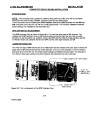
Figure 1-1
7109-C-229D
This
is the Optical
System Functional Diagram for a single-wavelength ellipsometer.
1-7
DESCRIPTION
L 116C ELLIPSOMETER
5.0
ELLIPSOMETER COMPONENTS
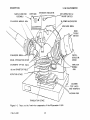
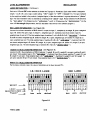
The principle components of the L116C Ellipsometer are identified in Figures 1 - 2 and 1 - 3.
5.1
Laser
A red laser assembly, with a fixed wavelength of 632SA (632.8 nm ), is adjusted to provide the
low - power (Class II, which is for under one milliwatt) light source. A built - in quarter - wave
depolarizer in the laser output produces a circular polarization of the beam.
NOTE:
When the beam attenuator ( see below J is out. the laser beam strikes the sample
wafer or table surface. both the polarizer and analyzer arms must be at the same angle of
incidence. Then the ellipsometer can make measurements and will be safe to work with. The
beam attenuator on any laser supplied to Gaertner is removed when the laser output is adjusted
to under one milliwatt.
5.2
Polarizer ( See Figures 1 - 1 and 1 - 2
Polarizer Drum and Prism.
J.
The polarizer prism, mounted in the polarizer drum, is a Glan
Thompson calcite prism that converts the circulany polarized light from the laser to linearly - polarized
light. Any given angle of prism orientation from 0° to 3600 can be set by adjusting the polarizer drum.
The angle can be set to within tenths of a degree by setting a number in whole degrees ( indicated on the
drum) just below zero ( 0 ) on the 0 - to - 1 vernier scale and then aligning a graduation on the vernier
scale to one on the drum scale. For automatic measurements, the user should fix the polarizer drum at
exactly 45° by inserting the locking screw into the drum's detent.
Compensator.
The compensator assembly is at the optical output of the polarizer prism, and has
a mica, quarter - wave plate, set at +90°. When this way plate is put in the laser light path, the linearlypolarized light from the polarizer prism is changed to circularly polarized light.
Beam Attenuator.
The beam attenuator ( more accurately called a beam blocker" lever, at the
polarizer module output aperture, is a manually - operated slide device to either block the incident beam
or to allow passage of the beam to the sample surface.
U
5.3
Sample Monitor Assembly
The Sample Monitor Assembly has both a tilt monitor and 39 - power, sample surface - viewing
microscope. Using the viewing scope function, the user can see the sample surface for damage or
imperfections. The light source for the surface illumination is built - in, originating within the sample
monitor assembly enclosed in a housing above the objective end of the sample monitor. The intensity of
illumination is charged by turning a control on the left side of the Sample Monitor Assembly.
1-8
7109-C-229D
DESCRIPTION
SAMPLE MONITOR
ASSEMBLY
L116C ELLIPSOMETER
EYEPIECE
EMISSION INDICATOR
KEY-OPERATED AC
ON/OFF SWITCH
39-POWER MICROSCOPE
POLARIZER MODULE ARM
ANALYZER DRUM
MODE
---r. ..-- TOGGLE
SWITCH
,
o
PHOTODETECTOR
COVER
MICROSPOT OPTICS (Opt.)
'ANALYZ ER
----I=".,--~- MODUL E
ARM
150 mm DIAMETER TABLE
ROTATION STAGE
COLORED
TEST JACKS
AND TRIMPOTS
VACUUM HOSE
TRANSLATION STAGE
Figure 1-2
7109-C-229D
These are the front-view components of the Ellipsometer L116C.
1-9
L 116C ELL! PSOMETER
DESCRIPTION
+90 0 COMPENSATOR
SAMPLE MONITOR ASSEMBLY
POLARI Z ER DRUM
0
0
0
0
0
0
00
0
632.8 nm (RED)
LASER
0
0
a
~------------MICROSPOT STOPS
(OPTIONAL)
/
7
INSTRUMENT
POWER SUPPLY
FUSE
COMPUTER
INTERFACE
RECEPTACLE
TO AC POWER
Figure 1-3
7109-C-229D
These are the Ellipsometer L 116C Components in this Rear View.
1-10
L116C ELLIPSOMETER
5.3
DESCRIPTION
Sample Monitor Assembly ( Continued)
Using the tilt monitor function, the operator can detect an out - of - flatness condition of the sample
surface and compensate for this condition. The amount of out - of - flatness is determined by observing
a reflected image projected as background on 90 - degree crosshairs in the eyepiece. Compensation is
accomplished by tilt adjustment of the sample table in X and Y planes. The tilt adjustment controls are on
the underside of the table. The Sample Monitor Assembly includes the following:
5.4
•
LED Meter
•
Emission Indicator
•
Electrical Control Group
• Key - operated ellipsometer and laser power ( ON I OFF) switch
• Illuminator and illumination intensity control
Reference Sample
A silicon substrate wafer reference sample with a single -layer transparent silicon oxide film ( thickness
of about 780A, which is 78 nm ) is supplied with the ellipsometer. Initially, the sample should be used for
obtaining sample measurements in the process of instrument familiarization. Periodically, the sample
should be used to obtain measurement data for comparison with previous data to verify that the
ellipsometer is in proper adjustment.
5.5
Analyzer
Analyzer Drum and Prism. The analyzer prism is in the analyzer drum and in the optical axis of the
light renected from the Sample Wafer ( Figure 1 - 1 ). The analyzer prism is identical to the polarizer
prism in that it is a Glan Thompson prism inside a motorized drum. During automatic operation, the
analyzer drum ( with the analyzer prism inside) is constantly rotated by the drive motor. Encoder and
optical switch assemblies on the analyzer shaft are slotted such as to allow the passage of light pulses at
discrete intervals of the analyzer rotation, from LED's to phototransistors which, in tum, generate the
pulses used during the measurement process.
Filter. A narrow - band, 632.8 nm ( red laser) optical interference filter is installed at the analyzer
output, and is used to block ali of the wavelengths except that of the laser beam.
Detector and Switch Assembly.
This unit is inside the photodetector cover with an access hole and
consists of a solid - state photodetector that produces an output current proportional to the intenSity of
the light from the analyzer prism; a current - to - voltage converter I preamplifier; analog output amplifier;
and three - position Mode Switch.
1·11
7109-C-229D
L116C ELLIPSOMETER
5.6
DESCRIPTION
Electronic Chassis
This assembly is in the ellipsometer base and consists of the analyzer motor drive, analog / digital
conversion, test jacks and interfaces to the computer.
5.7
Instrument Power Supply
This assembly is in the vertical enclosure, at the rear of the support frame. The power supply provides
the conversion of various line voltages, compensator control and laser drive.
5.8
Sample Stage and Table
The sample stage provides a combination rotary and linear manual positioning of the sample table,
allowing measurement at any point on the sample surface. This is achieved by linear translation in the
( + ) X direction from center and rotation from 0° to 3600 . The linear scale is graduated in one ( 1 ) mm
increments, numbered at 10 mm intervals from 0 to 75 mm full scale. The rotary scale is graduated in
1° increments, numbered at 10° intervals from 0° to 3600. See Figure 1 - 2 on page 1 - 9.
The table is vertically adjustable, so that the laser beam reflected from the sample surface is maximized
when entering the analyzer aperture. The vertical position is adjusted by rotating a knurled knob on the
support structure. (A clockwise rotation raises the table. ) A locking screw secures the vertical
adjustment.
The standard table will accept samples up to 150 mm ( 5.9" ) in diameter, and is tiltable up to one ( 1 )
degree in both X and Y planes from the predetermined level position established at Gaertner just before
the shipment of the ellipsometer. See the description of the Sample Monitor Assembly ( page 1 - 8 ).
A fine - motion vertical position adjustment option may be added to the table. An attachment for the
vacuum pump is on the right side of the stage. See Figure 1 - 2 on page 1 - 9.
Yellow plastic locator strips are supplied for use in centering a wafer sample on the table surface.
For example:
A plastic strip can be inserted into either the 3 - inch, 100 mm. 125 mm or
150 mm diameter groove in the surface of the standard table.
1-12
7109-C-2290
L 116C ELLIPSOMETER
6.0
DESCRIPTION
DETERMINATION OF PSI AND DELTA
The state of polarization of a beam is determined by the relative amplitude ( amplitude ratio) and the
relative phase shift ( phase difference) between the two component plane waves resolved from the
electric field of the beam. If the phase differences between the components is either 0° or 180°, the
beam is linearly polarized. All other phase differences result in elliptical polarization. When a
monochromatic beam of polarized light strikes the surface of a sample, the reflection of the light causes
a change in the relative phases of the component plane waves and a change in the ratio of their
amplitudes.
The angle DELTA ( A ) is defined as a change in phase difference. An angle PSI ( 't' ) is the
arctangent of the factor by which the amplitude ratio changes. The phase difference ( L\) and the
amplitude ratio ( \f' ) thus characterize the elliptically polarized light reflected from the sample surface.
These parameters are used to calculate the optical constants of bare surfaces and, if film covered, the
thickness and refractive index of the film. The refractive index Nf is used to detennine the physical
composition of the film and to establish the magnitude of the period, i.e., the thickness interval between
the repeating of ellipsometric readings.
Using the measurement data obtained from the two sets of light intensity readings, the computer
calculates DELTA for each set. The DELTA selected, to achieve optimum accuracy in computation
of optical constants and film thickness, is based on the following criteria:
Within 45° of 0° or 180 0 , DELTA is found with the +900 compensator in the laser
light path.
More than 45° from 0° or 180°, DELTA is found without +900 compensator in the
light path.
PSI is always obtained from the measurements without the +900 compensator in the light path.
1-13
7109-C-229D
L 116C ELLIPSOMETER
7.0
DESCRIPTION
STANDARD PROGRAM DESCRIPTION
One standard single - point program ( STD ) is supplied with each ellipsometer that has an IBM
computer.
The Standard ( Single - Point Program. STD (SC6A + SC7A + GC5A + SubCA) is for both
L 115C and L116C Ellipsometers. There are four subprograms:
•
GC5A
FILM: This subprogram determines the thickness and refractive index of
single - layer, transparent ( non-absorbing) film of silicon dioxide or
silicon nitride on a silicon substrate.
Data Output: Thickness, Index, PSI ( 'f' ), DEL ( " ), and the period.
There is a fixed index option.
•
SC6A
SPECIFIC: This is similar to the Film subprogram. Oxide or nitride films
are evaluated at an incidence angle of only 70°.
•
SC7A
TWO ANGLE: This subprogram for measures the thickness of silicon
oxide, silicon nitride or other nonabsoroing film on silicon substrate. Two angle measurements are at 50° and 70° incidence angles. It determines
the absolute thickness of thick films based on the order or period from a
matched measurement at each angle.
Data Output: Matched thickness values. Index and a listing for each
angle.
•
SubCA
SUBSTRATE: This subprogram determines the optical constants of a
bare substrate. These constants must be known before to making thin film
measurements.
Data Output: PSI ( 'f' ), DEL ( " ), real ( Ns ) and extinction ( Ks )
refractive indexes constants of the substrate.
1-14
7109-C-229D
L 116C ELLIPSOMETER
OESCRIPTION
NOTES:
1-15
7109-C-229D
L116C ELLIPSOMETER
1.0
OPERATION
PREMEASUREMENT SETUP
The premeasurement setup includes setting the polarizer and analyzer angle of incidence, turn - on and
the warmup of the ellipsometer, and initial alignment of the sample stage
1.1
Setting the Angle of Incidence
CAUTION
Do not grasp the 632.8 nm ( red) laser when
setting the polarizer arm. That may easily cause
laser misalignment.
a.
Grasp the polarizer arm ( but never the laser ); and at the rear of the arm, loosen clamp screw
about one tum.
b.
Pull outward on spring-loaded locator pin next to the clamp screw, and move the arm to within
v. - inch of the 70° angle of incidence.
C.
Release the locator pin, and move the arm slowly until the pin seats in detent on vertical plate.
Tighten clamp screw. ( This accurately sets the angle of incidence. )
d.
Repeat steps a through c to set the analyzer arm angle of incidence, but do not apply pressure to
the PO ( pholodetector ) cover.
NOTE: Follow steps a to d also when setting the angle of incidence at any other angle" The
detented angles are 30', 45' through 80' at 5' steps. There is also 90', which is only for
adjustments. See page 1 - 4 of the Description section about the beam size at each
angle.
e.
Set the polarizer drum to 45°, and secure by inserting the locking screw in the hole on the side of
drum.
• See the Caution note at the top of Figure 2 - 1 about the arms with the optional Microspot
optics at the 90' angle of incidence. Note the statement ( with the asterisk) just above the
caption about the fact that with the microspots. the arms cannot be set at 90' with the larger
table.
7109-C-2290
2-1
OPERATION
L116C ELLIPSOMETER
CAUTION ( For 90' Angle of Incidence
l*
If the L 116C has Microspot Optics, rotate the 150 mm table so
that Its lifting slot is under the analyzer Microspot. Move the
table to the left and down so that neither Microspot OptiC will
contact the table when both of the anns are at 900 .
SAMPLE ILLUMINATOR CONTROL
SAMPLE MONITOR
ASSEMBLY
+90· COMPENSATOR POSITIONER
MODE
~ DRUM
POLARIZER DRUM
_ _ _ _ _ _ _ _ _,
LOCKING SCREW
SWITCH
(TOGGLE)
PO COVER----.J
0
0
ANALYZER-----__~~
ARM
~~~
,
0
•
•
ELLIPSOMETER
SLOW-BLOW
FUSE, .75A
(115 or 230V)
POLARIZER ARM
0
00
0
632.8 nm (RED) LASE
•
0
0
••
'LOCA TOR PIN
L
I
CLAMP SCREW
MICROSPOT STOPS (Opt.
GP I 0 SOCKET, FOR THE
CABLE TO THE COMPUTE
• The optional 200 mm dia. table cannot be moved out of the way of the optional Microspot
Optics. Thus, the arms cannot be set at 90· with both of these options
Figure 2 - 1. This is the rear and left view of the L116C Ellipsometer ( with the standard table ).
2-2
7109-C-229D
L 116C ELLIPSOMETER
1.2
OPERATION
Turn - on and Warmup
a.
Connect the ellipsometer and the computer according to the Installation section.
b.
To turn on the ellipsometer and the 632.8 nm ( red ) laser, turn the key - operated power
switch on the Sample Monitor Assembly fully clockwise, ON ( Figure 2 - 2 ).
The Emission Indicator should illuminate. A 15 - minute minimum warmup of the 632.8 nm
laser is recommended before performing eliipsometeric measurements. Set the Mode
( toggle) switch ( Figure 2 - 1) to AS. The following describes the three Mode Switch
positions:
C.
•
Manual ( M ) position:
This
•
Autoset ( AS ) position:
This is used during premeasurement setup
( Sample Stage alignment)
•
Automatic ( A ) position:
This is used for automatic measurement ( with the
Drum rotating)
IS
used during alignment and calibration
Pull to open the beam attenuator, and proceed with the" Sample Table Vacuum and
Alignment ".
1.3
Sample Table Vacuum and Alignment
Vacuum
At the center and rear of the table are small (#0 - 80 x 1/8" round head, stainless steel)
plugs that can be removed when a vacuum pump is connected to the ellipsometer.
Remove only the plugs that will be under the wafer, but not the plug under the edge of the
wafer ( see Figure 2 - 3 ).
Alignment
Follow this procedure, beginning with step a ( see Figure 2 - 4 ).
a.
With tweezers, air wand, etc. put a reference sample or single - layer, nonabsorbing wafer of
a known film thickness on the table via the insertion slot. Turn on the vacuum pump if
connected.
b.
Loosen the Sample table clamp screw.
c.
Look into the Sample Monitor Assembly eyepiece, tum the illumination control for the
desired illumination. Move the eyepiece in or out for the sharpest of the 90° crosshairs.
d.
Rotate either of the Sample Monitor Control knobs in Figure 2 - 2 so that it brings a
reflected image of the two diagonal lines into view ( if already not in view), as seen in the
eyepiece.
( Section 1.3 continued on page 2 - 6 )
2-3
7109-C-229D
L116C ELLIPSOMETER
OPERATION
EYEP I ECE
EMI SSI ON
INDICATOR
ON/OFF KEY
SAMPLE
ILLUMINATION
CONTROL
.-._..................._-.... _....... -......
f
LED METER
This meter uses a row of tiny red lights
to show the analog output of the photodector {PO} circuit.
A green light on
the right shows that the PO output is
Iloverscale".
A green light at the left
means that the PO output is negative.
•
~..
•
o
••
,39-POWER MICROSCOPE
o
During measurements, the Mode switch is
at A; the drum rotates; and the LED
meter display swings with the rotation.
Three or less tiny red lights indicate a
zero PO output.
SAMPLE
MONITOR
CONTROL
Figure 2 - 2. These are the ellipsometer controls and indicators on the Sample Monitor Assembly.
2-4
7109-C-229D
OPERATION
L 116C ELLIPSOMETER
INNER
GROOVE
150 mm (OUTER)
GROOVE
r~
,
125
mm
100 mm
CENTRAL
HOLE
3 INCH
Figure 2 - 3. This is a top view of the 150 mm (almost 6 inches) diameter sample table.
See Figure 6 - 1 in the Optional Components section for the top view of the
Optional 200 mm diameter table.
2-5
7109-C-2290
L 116C ELLIPSOMETER
1.3
OPERATION
Sample Table Vacuum and Alignment (Continued)
e.
Observe the intersection of the two wide diagonal lines and the intersection of the narrow
lines. Slowly rotate as needed the X and Y plane tilt adjustment controls to center the
diagonals precisely on the crosshairs intersection, This makes corrections for the sample
surface out - of - flatness condition.
NOTE:
The width I height of the intersection of the diagonals IS four arc minutes. This may
be used as a reference in determining the approximate tilt adjustment needed.
f.
Using the adjustment wheel under the rear of the table, raise or lower the table to obtain the
maximum reading on the LED meter. A clockwise rotation of the wheel raises the table.
9.
If the reading from step e overshoots the LED meter upper limit, tum the analyzer drum to
lower the gain. Then readjust the table slightly for a maximum reading. Repeat the
adjustment of the drum and table vertically as needed for a maximum reading within the range
of the LED meter.
h.
Return to steps c through 9 as often as needed until each adjustment is correct.
i.
Tighten the sample table clamp screw.
J.
See the standard single - point program instructions ( such as STD ) in the Standard
Programs sections for the loading instructions, and use the Film program or subprogram.
Proceed to make a measurement.
k.
Compare the thickness data measurement with previously acquired sample thickness data.
The compared data should be within ± 3A ( ± .3 nm ).
2·6
7109-C-2290
QPERATION
L 116C ELLlPSQMETER
VERTICAL POSITION ADJUST
TIL T ADJUST
(X-PLANE)
VERTICAL ADJ. CLAMP - - - - - -
~
~~====-:=:;::::~:::::
it..
~-"
.
'--
"TILT
ADJUST
(Y-PLANE)
<=>
I
/4
ROTATION
CONTROL
X-TRANSLATION
CLAMP
STAGE (+) X TRANSLATION CONTROL
Figure 2 _ 4. This is the L 116C Sample Stage and Table.
2·7
7109·C·229D
OPERATION
L 116C ELLIPSOMETER
2.0
MEASUREMENT PROCEDURE
Place the sample wafer on the sample table, load the program software into the computer, and initiate
the measurements_ Once the measurements are started, you press the keys as the screen and
instructions request, then measurements are automatic.
Some measurements can be made after a 15 - minute ellipsometer warmup, the stability of the laser
improves after a few hours, which is better for important measurements_ If the ellipsometer is in use
several times a day, the laser should operate continuously.
WARNING
To avoid the hazard of laser beam dispersion, the beam attenuator
must be closed while you adjust the polarizer or analyzer arm, or
when the two arms are not at the same angle of incidence.
2,1
Standard and Optional Single - Point Measurement Programs
Valid measurements are dependent upon the selection of a program applicable to the sample being
measured, and correct interaction by the user with the computer. The standard programs supplied with
the ellipsometer are in the Standard Programs section. The optional programs available by special
order are identified in the Optional Programs section.
Ideally, the table need not be vertically readjusted between measurements on a series of samples, if all
samples in a given lot are plane - parallel, about equal in sample thickness, and no dust particles or
other foreign matter are deposited on the surface of the table.
2-8
7109·C·229D
OPERATION
L IISC ELLIPSOMETER
2.2
Automatic Motor Turnoff
An automatic turnoff of the rotating analyzer motor is provided to prolong its life. The motor will
automatically turn off about five minutes after the last measurement.
Characteristics
1
If the ellipsometer is on with the computer off and the mode switch is set to A, the analyzer
drum will rotate once and stop.
2.
If both the ellipsometer and the computer are on and the mode switch is set to A, the analyzer
drum will rotate for five minutes before auto tum off.
3.
When stopped, the motor will automatically turn on when a measurement is initiated, and
successive measurements will extend the five - minute interval.
2.3
Loading Programs
a.
Load the program software into the computer. The loading instructions are in the
" Installation" section. Use the Film Program or Film Subprogram of the" Standard
Programs" section.
b.
Place sample under test on the table, and proceed with the measurements.
2.4
Placement of the Sample
B.
Turn on the vacuum pump if it is connected. Remove the tiny plugs in the grooves in the
stage that will be under the sample. Reinstall any plug that will be under the edge of the
sample.
b.
Place the sample under test on the stage, and raise or lower the polarizer - analyzer
module as needed. (Refer to Subsection 1.3, "Sample Table Vacuum and
Alignment ". steps a through k.)
C.
Set the Mode Switch to A. The analyzer drum should rotate.
d.
Proceed with the measurements by initiating data entry according to the desired program in
Section 3 or 4.
At the completion of the measurement sequence, set the Mode Switch to AS; and remove the sample
from stage. Put on the next sample, and align the arms, as needed, with the knob on the top of the
ellipsometer. Set the Mode Switch to A, and proceed with the measurements of the next sample
( with the analyzer drum rotation ).
2-9
7109-C-229D
L116C ELLIPSOMETER
3.0
OPERATION
CLEANING AND LUBRICATION
These maintenance instructions are operator -level procedures for routine servicing. See the Service
Section about trouble analysis, and replacement of defective components, which are for qualified
service personnel. Instructions are not included for the replacement of any laser or polarizer / analyzer
optical or precision electro - mechanical components. Contact Gaertner Scientific about the repair or
replacement of these items.
3.1
Cleaning
Interior cleaning of the ellipsometer ( i.e., the detector and switch assembly, monitor assembly and
instrument power supply) should not be needed. These units are designed to keep foreign matter out.
When not being used, the ellipsometer should be enclosed by the dust cover supplied with the
instrument. Exposed optical surfaces may be cleaned with a camel - hair brush or clean, dry
compressed air ( not to exceed 5 PSI). All other external surfaces may be wiped clean using a soft,
lint - free cloth. If a solvent is needed, a cloth dampened with wood or isopropyl alcohol is
recommended.
3.2
Lubrication
Periodic lubrication is not required.
2-10
7109-C-229D
L 116C ELLIPSOMETER
INSTALLATION
The L 116C Ellipsometer is shipped fully assembled, along with needed items, in a single shipping
crate_
•
L116C User Manual
•
Ellipsometer I Computer Interface Cable
• •
GPIO Interface Card (for IBM PS I 2·25 Series Computers or Equivalent )
•
Software Programs
•
Silicon Wafer (Reference Sample)
•
Dust Cover
* This component is supplied to customers who have their own computers. But computers that are
shipped with the Ellipsometer will have the GPIO card already installed.
UNPACKING
Remove the protective wrapping from the Ellipsometer. Remove the lag bolts that secure the hold·
down clamps to base of the Ellipsometer. Remove the hold-down clamps. This allows removing the
Ellipsometer from the shipping crate base platform.
NOTE: Store the shipping platform, shipping crate components and protective wrapping for use
in the event of reshipment to Gaertner for repair.
WHEN PACKING THE ELLIPSOMETER FOR RESHIPMENT TO
GAERTNER FOR REPAIR, INCLUDE THE SOFTWARE PROGRAMS AND
INTERFACE CABLES (WITH GPIO INTERFACE CARD, IF APPLICABLE).
CONTACT GAERTNER FIRST.
CAUTION
In event of reshipment, precautions must be taken to ensure that ( 1 )
the polarizer arm is set and clamped at 50" angle of incidence and ( 2 )
the analyzer arm is set and clamped at 50" angle of Incidence prior to
packing.
This will prevent a possibility of damage to the helium - neon ( red )
laser and the analyzer module
5-1
7109·C·229D
L 116C ELLIPSOMETER
AC POWER PLUGS
INSTALLATION
Gaertner Ellipsometers are supplied with U.S. plugs (NEMA 5-15P) If it necessary to change the
plug, the following guidelines apply:
'
-· i
m
.
"uu. .., .
U In:J.I.
ltJ
Great Britam, Cyprus, Nigerta,
Rhodesia and Singapore
Underwriter's
Laboratory approved
for the United States,
Canada, Japan,
Mexico, Philippines
and Taiwan
AlC1t2
UL approved for the
U.S.
Australia and New Zealand
CEIT.vn
•
Eastern and Western Europe,
Saudi Arabia, and United Arab
OL. -0
Switzenand
o
Republic
Figure 5-1.
NOTE: Ali plugs are for single-phase power and are viewed ( above) from the connector end.
The prongs are:
Line or active conductor, also calied " live' or "hot". The insulation is black.
• L=
Neutral or identified conductor. The insulation is white.
• N=
Earth or safety ground. The insulation is green.
• E=
5-2
7109-C-2290
L 116C ELLIPSOMETER
INSTALLATION
INSPECTION
Thoroughly inspect the Ellipsometer for shipping damage. If there is damage from transit, notify the
carrier.
Verify that a key is installed in keylock switch on the right side of the Sample Monitor Assembly
( above the sample table) and is off. Check that a good fuse is in the Ellipsometer.
Verify that all of the applicable items have been included in the shipment.
LOCATION CONSIDERATIONS
The L 116C Ellipsometer is designed for use in either a production or laboratory facility under relatively
constant room temperature and a relatively dry, dust - free atmosphere. The Ellipsometer requires a
clean, level solid work. surface sufficient to also accommodate the interfaced computer. The ac line
vOltage must be free of large transients having harmonics in the range from audio frequencies to
several megahertz Do not obstruct the ventilation holes on any of the equipment.
INTERCONNECTIONS
00 NOT plug or unplug any component into or from ae power or make connections to other equipment
with its power ON I OFF switch ON I
The ae line cable for the Ellipsometer and the laser is on the rear of the instrument and may be
labeled INPUT POWER.
CAUTION
Verify that the power switches on all of the components are OFF
before connecting or disconnecting the interface cabling.
A connection diagram for the L 116C is shown in Figure 5-2.
Ellipsometer and Computer See Figure 5-3 (Ellipsometer Rear View) and Figure 5-4,
IBM PS I 2·25 Computer.
5·3
7109-C·229D
L116C ELLIPSOMETER
INSTALLATION
COMPUTER IBM PS 12-25 AND PRINTER HP THINKJET HP2225C OR EQUIVALENT
Connect the Centronics Interface Cable ( 71 08-E239T ) at the parallel receptable at the rear of
the computer and the rear of the ThinkJet printer.
See Figure 5-3 (IBM PS 1 2-25 ).
Hand tighten the connector thumb screws.
5-4
7109-C-229D
INSTALLATION
L116C ELLIPSOMETER
IBM DISPLAY
UNIT
GPIO COMPUTER INTERFACE
CABLE DR. # C-10161-45DB
COILED CABLE
IBM PC ORPS
COMPUTER
IBM
KEYBOARD
ELLIPSOMETER
L116C
0
PARALLEL CENTRONIC S
INTERFACE CABLE
DR. # 7108-E239T
THINKJET PRINTER
HP2225C PRINTER
Figure 5-2. This is the Ellipsometer L 116C Interconnection Diagram.
The computer that Gaertner will supply with the L 116C
is the IBM PSI 2-25.
5-5
7109-C-229D
L 116C ELLIPSOMETER
INSTALLATION
0
•• " •
•
00
ELLIPSOMETER
SLOW-BLOW
FUSE, .75A
(115 or 230V)
0
RED ( 632.8 nm
LASER
D
•
GII_-_~
0
,/
MICROSPOT STOP
GPIO SOCKET, FOR THE
CABLE TO THE COMPUTER
TO AN AC OUTLET
Figure 5-3. This is the rear and left view of the L 116C Ellipsometer wtth the 6" Diameter
Table and the 632.8nm helium-neon laser.
5-6
7109-C-229D
L116C ELLIPSOMETER
TO AC POWER
INSTALLATION
RS-232C SOCKET
CARD AND SOCKET FOR THE GPIO
CABLE TO THE ELLIPSOMETER
PARALLEL SOCKET FOR THE
CENTRONICS INTERFACE
CABLE TO THE PRINTER
Figure 54. This is the IBM PS/2-25 computer and its connections, which is generally
used with the L116C Ellipsometer and is the one that Gaertner will supply
with that Ellipsometer.
5-7
7109-C-229D
L 116C ELLIPSOMETER
INSTALLATION
SOFTWARE INSTALLATION AND LOADING
NOTE:
Wherever this instruction tells you to type in some specific characters, the characters
are in boldface and just after" TYPE ". Type in the Characters, and press ENTER.
Software Installation and Loading.
The Ellipsometer should be on 15 minutes before using, but 30 minutes would be better. Tum ON
the computer display unit and the printer. Insert the program disc into drive A, and tum ON the
computer. The program should boot automatically. If DOS is already loaded, place the program
disc in the appropriate disc drive, i.e., 1.2M drive for programs using IBM PC AT and 720k
for PS I 2 or 360k drive for programs using IBM PC or IBM PC XT.
For exampte, if .. A:\ .. or .. A>" is displayed on the screen, drive A is the default drive ( the drive
that the computer selects when the computer is turned ON). If the program disc is compatible with
drive A and inserted into drive A, then just type AUTOST and press ENTER The program will load
and start running.
5-8
7109-C-229D
INSTALLATION
L 116C ELLIPSOMETER
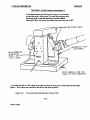
COMPUTER CIRCUIT BOARD INSTALLATION
INTRODUCTION
NOTE: If the computer was supplied by Gaertner along with the L 116C, then the circuit boards
mentioned here were already installed. Ignore this and the next three pages.
These instructions are for installing the GPIO Interface Card and Cable assembly into the IBM and
IBM compatible computers for use with the l116C Ellipsometer. The computer Interface Card DIP
switch settings and installations are described here.
GPIO DIP SWITCH ADJUSTMENT
The GPIO Interface Card is shown in Figure 5-5. This card has three sets of DIP switches. The
smallest set of DIP switches, close to the card connector on the far right, has six or ten tiny slide
switches. On the six-switch unit, switches 1 and 2 are OFF and the other four slide switches are ON.
On the ten-switch unit, switches 5 and 6 are OFF and the other eight switches are ON.
LASER RETARDATION
The other two sets of DIP switches are on a small board near the middle of the card. Each of these two
larger sets of DIP switches has 12 tiny rocker switches, one unit ( of 12 switches) is for the infrared I
blue laser and one for the red. The rocker switch settings are different for each laser. The settings of
the infrared I blue laser switches should be closed if the instrument has only a red laser.
__------I~EID LASER DIP SWITCHES
6 OR 10
DIP
SWITCHES
' -_ _ _ _ I.R. LASER DIP
SWITCHES
Figure 5·5. This is photograph of the GPIO Interface Card.
5·9
7109·C·229D
L116C ELLIPSOMETER
INSTALLATION
LASER RETARDATION (Continued)
Each set of 12 small DIP rocker switches is divided into 3 groups of 4 switches. Each rocker switch is assigned a
weight ( 1, 2,4 or 8 ) and a logic ( switch setting: " ON .. I open =1; " OFF" I closed
= 0). The logic multiplied
by the weight and added to the products ( weighted logics) of the other switches in a group determines a " place ..
digit. The laser retardation value is obtained by combining the 3 .. place" digits. Rocker switches 1 to 4 determine
the "tens place"; 5 to 8 determine the
II
units place "; and 9 to 12 determine the" decimal place ". ( In the
case of 3-Wavelength Ellipsometers, the loR. retardation value will be in the software program. )
RED LASER RETARDATION (See Figure 5-6 )
Assume the red laser retardation is 96.6. Switch 1 is open; its logic, 1, multiplied by its weight, 8, gives a weighted
logic of 8. Switch 4 is open ( logic 1, weight 1 ); weighted logic is 1. Switches 2 and 3 are closed ( logic 0 );
weighted logic of each is O. The total weighted logic of switches 1 to 4 is 8+0+0+1=9 (jf tens place"). Switches
5 and 8 are closed: weighted logic O. Switch 6 (weight 4) is open; weighted logic is 4. Switch 7 (weight 2 ) is
open; weighted logic is 2. The total weighted logic of switches 5 to 8 is 6 (" units place"). Switches 9 and 12
are closed; weighted logic is O. Switch 10 (weight 4) is open; weighted logic is 4. Switch 11 (weight 2 ) is open;
weighted logic is 2. The total weighted logic of switches 9 to 12 is 6 (jj decimal place <I).
1523nm I.R. BLUE LASER RETARDATION (See Figune 5 -6)
Assume the I.R.I blue retardation is 103.9. Switches 1 (weight 8) and 3 (weight 2) are open; switches 2 and 4
are closed. Total weighted logic is 10 ( j j tens place " ). Switches 5 and 6 are closed; switches 7 (weight 2) and
8 (weight 1 ) are open. Total weighted logic is 3 (<I units place 10). Switches 9 (weight 8) and 12 (weight 1 )
are open; switches 10 and 11 are closed. Total weighted logic is 9 (<I decimal place").
830nm I.R.t BLUE LASER RETARDATION
For the diode ( infrared) laser, the value of retardation will be lower (around 70 ).
I.R. / BLUE LASER
~~]~]n~l~~~
~Mll~~]~1
• x x x x x x x x x x x
x x x x x x x x x x x •
I 0 100 0 1 1 1 0 0 1
10
3
9
unll.
decimal
tens
1 o 0 I 0 1 1 o 0 1 I 0
6
6
9
1 2 3 q 5 6 7 8 9 10 11 12
0
1
WEIGHT
;>
>-
LOGIC
WEIGIITED LOGIC ~
"PLACE"
;;:..
842 1 8 q 2 1 842 1
Figure 5·6
7109·C·229D
RED LASER
5·10
8 4 2 1 8 4218q21
tens
units
decimal
Ll16C ELLIPSOMETER
INSTALLATION
IBM PS 12-25
This computer is the one most often used with the L 116C Ellipsometer. To install the GPIO Interface
Card, refer to" IBM Operations and Starter Diskette ", first edition ( June 1987). Section 2 is
" Installing Your Options ". The cover is shown removed on pages 2-3 and 2-4. The circuit board
installation is shown on pages 2-13 and 2-14, and the GPIO Interface card should be installed in the
lower expansion slot. The cover is reinstalled according to pages 2-16 and 2-17.
IBM PS 1 2-25 286
The differences between this computer and the one in the paragraph above include the VGA Plus
circuitry and a hard disc in this computer. The rear panel socket arrangements are virtually the same.
The GPIO card should go in the lower position. See Section 3 ( pages 3-18 to 3-23) of the Computer
Manual, " IBM Personal System 1 2 Model 25 286 Guide to Operations" ( 1990 ), for the card
installation.
IBM PSI 2-30
.. IBM Personal System 12 Model 30 Guide to Operations" bookiet (copyright 1987 ). Section 3 is
II Installing Your Options n. The cover removal instructions are on pages 3-3 and 34. The adapter
( Interface Card) Instructons are on pages 3-6 to 3-8. The GPIO Interface Card ( with the three DIP
switches) is mounted in the middle position. The cover is reinstalled according to page 3-9.
IBM PS 1 2-30 286
This computer is basically the same a the IBM PS I 2-30. Refer to computer manual, " IBM Personal
System 1 2 Model 30 286 Guide to Operations" ( 1988 ), concerning card installation.
IBM PC AT
The Interface Cards are installed vertically according to the IBM PC AT" Installation and Setup"
manual (copyright 1984)_ Section 2 describes the cover removal procedure. Section 3 is the
.. Internal Option Installation ", Page 3..a shows the eight vertical positions available. The GPIO
Interface Card can be installed in any of these eight positions. Section 4 is for the cover installation.
5-11
7109-C-229D
Ll16C ELLIPSOMETER
SAMPLE STAGES
Hand Positioning Stages
L 116HXY6 This stage accommodates 6-inch samples and enables the sample table to
be moved by hand in X, Y and 8 directions to facilitate at any desired point on the sample
sulface. The X and Y coordinates translation facilitates measurement on a rectangular or grid
pattern; zero ( 0 ) to 2 inch left - to - right translation ( X direction) , 1- inch in the - Y
direction from center, and y,- inch in the +Y direction. Total rotational travel ( 8 direction) is
0" to 360". If the white plastic retainers are removed from the table, translation in the +Y
direction is increased to 1~inch.
Ll16HXY5 This stage is identical to the L 116HXY6 stage except that the table will allow
measurements on samples no greater than 5 inches in diameter. Front-to-back translation
( Y direction) is:t 1- inch from center.
Micrometer Positioning Stages
L 116MXY6 This stage is identical to the L 116HXY6 stage except micrometer thimbles are
added to allow fine motion translation in the X and Y directions to facilitate positioning within
rectangular smbe lines. One division on the thimble equals O. 001- inch. This stage is
especially useful with the Microspot Optics Option L 116MS accessory.
L 116MXY5 This stage is identical to the L 116MXY6 stage except will allow measurements
on samples no greater than 5-inches in diameter.
FINE MOTION HEIGHT ADJUSTMENT L 117FM This feature may be added to any type of
sample stage, and comprises a rotatable inclined plane acting through a transfer plate and the
coarse height adjustment to raise or lower the table 0.010 inch maximum (from mid-position
reference) after setting of the standard height adjustment. One half turn of the adjustment
knob equals O. 010 inch. The adjustment knob is at mid-position when the center line of the
reference hole on the knob is coincident with the centerline of the table clamp screw.
Clockwise rotation of the adjustment knob raises the table; counterclockwise rotation of the
adjustment knob lowers the table.
6·1
7109·C·229D
L116C ELLIPSOMETER
OPTIONAL COMPONENTS
MICROSPOT OPTICS L 116CMS ( Gaertner Installed)
This option has a projector optic that reduces the normal 1 mm diameter beam at the sample
surface down to 0.015 mm (to measure very small areas) and a receiver optic (for added
efficiency). See the table in Subsection 1.0 (Specifications) in the" Description" Section
of this user manual.
NOTE: The table in Subsection 1.0 (Specifications) shows the dimensions of the laser beam
on the sample with and without the Microspot Optics at different angles of incidence, ,.
INTERFACE LRS232
This option enables the user to send or receive serial data via an interface with RS-232C
compatible equipment such as a large-scale ( host) computer, data terminal and modems.
Includes interface cable, modified software and program User Instructions.
Contact Gaertner for details on specific data communication specifications.
VIDEO MONITOR L 115VM
This option allows the ease of monitoring a wafer pattern display on a CRT screen in addition to
the standard viewing microscope. An MIT switch is usually mounted on the front of the Sample
Monitor Assembly when a video monitor is included with an ellipsometer.
WAFER HANDLER L 116WH
Model L 116WH Wafer Handler penn its unattended automatic measurement of up to 25 wafers
from a cassette. The randon- access indexer on the Wafer Handler is ultra clean with the
mechanism fully contained within the housing so that there are no moving parts near the wafer.
The n frog-leg" type of motion of the ann is Simple, clean and gentle.
200mm ( 7.9 inches diameter) SAMPLE TABLE
This larger table is for 3" ( 76 mm ). 100 mm, 125 mm, 150 mm and 200 mm wafers for film
measurements. See Figure 6-1 for a top view of this table.
NOTE: If an ellipsometer has a 200 mm diameter table and the Microspot Optics, it is not
possible to move this table out of the two anns so that they can be set at a 90° incidence angle;
thus ignore any instructions that call for setting the arms at 90°.
6-2
7109-C-229D
OPTIONAL COMPONENTS
L 116C ELLIPSOMETER
FINE MOTION HEIGHT COMPONENTS
1.0
Description
This feature may be added to any type of sample table and consists of a rotatable inclined plane acting
through a transfer plate and the standard height ( vertical position) adjustment to raise or lower the table
O.254mm ( 0.010 inCh) maximum ( from the mid - position reference) after setting the standard vertical
position. One half tum of the knob moves the table 0.010 inch. The knob is at the midposition when the
center line of the reference hole on the knob is at the centerline of the table clamp screw.
A clockwise rotation of the knob raises the table ( CCW lowers the table ).
2.0
Using the Adlustment (See Figure 6-2.1, page 6-2.2)
•
Loosen the table clamp screw.
•
Set the reference hole at mid - position.
•
Use the coarse height adjustment to raise or lower the sample table to the approximate
height required.
•
Rotate the fine motion up to a one - half tum in either direction to obtain the required
height.
•
Tighten the table clamp screw.
6-2.1
7109-C-229D
L116C ELLIPSOMETER
FINE MOTION HEIGHT ADJUSTMENT L117FM
ST ANDARD SAMPLE TABLE
COARSE HE I GHT ------7'
ADJUSTMENT KNOB
-----,
,,
L - __
REFERENCE HOLE
SHOWN IN
MID-POSITION
I
r--T .,-----
,
,
I
'
~
_ _ _TRANSFER
===f~
LATE
FINE MOTION HEIGHT
ADJUSTMENT KNOB _ _C>
Figure 6-2.1 Front and side views of the L117FM Fine Motion Height Adjustment Component.
6-2.2
7109·C-229D
L116C ELLIPSOMETER
OPTIONAL COMPONENTS
176 MM
INNER
GROOVE
160 MY
,
I
!
100 MM
----
~.::;;.
3 INCH
Figure 6-1, This is a top view of the 200mm ( 7.9 inches) diameter sample table.
6-3
7109-C·2290
SERVICE
L116C ELLIPSOMETER
1.8
TROUBLE ANALYSIS
This ellipsometer should have long-life, trouble-free operation. In the event of a malfunction, symptoms
are readily traceable by the use of built-in test jacks and intermediate check points This should be
done by qualified service personnel. Fault isolation involves trouble-shooting to identify the cause of
failure only to a component or assembly readily removable for further fault isolation and repair or
replacement. During automatic operation, a malfunction is usually shown by no measurement data,
inconsistent measurements, or even operator-induced errors.
1.1
Measurement System
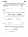
During automatic operation, the analyzer drum (with the prism inside) rotates at a speed regulated by a
closed-loop, motor-speed control system. (See Figure 7-1, next page.) Motor pulses originating at
discrete intervals from an encoder are amplified and applied to the input of a motor speed controller.
Within the encoder, the pulses are derived from a phototransistor circuit activated by a light emitting
diode ( LED). Actual motor speed is determined by frequency-te-voltage conversion of the input. This
voltage is compared to an extemally preset reference voltage. The result of the comparison controls the
drive voltage to the motor, keeping the motor speed constant. A" stall timer" prevents motor bum-out
in the event of a mechanical stall.
Intensity readings of the reflected light, as sensed by the photodetector, are taken at 5° intervals during
one revolution of the analyzer prism, beginning at 0° and ending at 355°. The readings are taken in the
dual mode, sequenced under program control via input from the computer. One set of readings
( 72 data paints) is taken with the +90 0 compensator in the optical path. The other set of readings is
taken with the compensator withdrawn from the optical path.
The output current of the photodetector is converted to an analog voltage varying sinusoidally in
amplitude and proportional to the intensity of the reflected light. The analog output is amplified and
applied to the input of an analog-to-digital ( A I 0 ) converter. A zero offset adjustment in the
photodetector circuit is factory preset to ensure optimum accuracy in measurement, especially for very
thin films. After each set of readings, the maximum analog output is checked by the computer software.
If measurement accuracy can be improved by changing the gain, the CTL 1 input logic will switch the
gain range and a repeat set of readings will be taken. A logic" 0 " closes the switch, decreasing the
gain; a logic" 1 " opens the switch, increasing the gain.
A reference pulse from an optical switch and between 356 0 and 359 0 of the analyzer drum rotation,
initiates the measurement cycle. The reference pulse is derived from a phototransistor circuit activated
by a LED. If a peripheral control ( PCTl ) signal from the computer is present during the period of the
reference pulse, indicating that the computer is ready to accept a reading, a timer is activated
(tumed on).
( section 1.1 continued on page 7-4 )
7-1
7109-C-2290
SERVICE
L116C ELLIPSOMETER
r-----------------1
1
Vac---:~
1
FULL
WAVE I--~ SWITCH
RECT
'SOLENOID
1
1
f---:'::'
POSITION
COMPENSATOR
1
COMPUTER
INTERFACE
1
r-----------1 r-----------------------------1
PIO ANALYZER
MODULE
tri\ 1 1
1
1
PIO
ENCODER
91
1
I
PIO ELECTRONIC
CHASSIS
f,\j\ I l L . TIMER
OPTICAL I
SWITCH r-REFERENCEI
LOGIC
~==d'Y=-r-r·~~
MOTOR DRIVE
BLy TL 0
(TO ANALYZER)!
I.
I.PCTL
C-:\
P/O
ENCODER
1
TIMER
I--~_-----I
,0 YEL
~-~
AMPL I-----I-___~
TRIGGER
'1 LOGIC
COUNT
1
RESET
lORN
~II
° GR~
ON
I
AID
--'" TI ME
, DELAY
I
I
1
PREAMPL
,-
1
1
,-
rrT
AMPL
ZERO OFFSET
ADJUST
I
,
r
Lf---------
1
1
1
1 LED
- , METER
-----1
BIT ,IIMSB)
PD OUT'
AID
AID
I
RED
1
I
BIT '2 (LSBL
OFFSE'~
ADJUST ~
"-_--I
r
L _____________ I
Figure 7-1. This is the Measurement System Functional Diagram.
7109-C-229D
PFLG
l.en ,
PHOTODET r1 ~--=_;r~~l~l------~t~B~U~FF~E~R_1r----J
AND
1..1
W
1
1
r
1 1
1
°
MOT R
I CONTROLLER
AMPL
1 1
1
1
I
1
MOTOR
1
1
BRN
SPEED :...
ADJUST ~
7-2
SERVICE
L 116C ELLIPSOMETER
+5V
REFERENCE
PULSE
OV
~
I
+5V
1
COUNT
PULSE
lr--
~
OV
>1
MEASUREMENT CYCLE
~
+5V
PRG
OV
-
lr
tr
~
rt=
~
r
FIRST REAOING
LAST READING
>U
+5V
PCTL
l
OV
+5V
MOTOR
PULSE
OV
~
STORE DATA'
PROCESS DATA
-
ANALYZER DRUM POSITION
• The STORE DATA pulses will not appear in some makes of computers.
Figure 7-2. These are typical pulses during the Measurement Cycle.
710S-C-22SD
~
7-3
1
~
SERVICE
L 116C ELLlPSQMETER
1.1 Measurement System (Continued)
For the first set of readings count pulses, starting at the 0" position of the analyzer rotation, trigger the A I 0
converter to accept the photodetector analog output. The count pulse is derived from a phototransistor
circuit activated by a LEO in the encoder, in the same manner as previously described for the motor pulse.
About 30 microseconds later, allowing time for A I 0 conversion, a peripheral flag ( PFLG ) signal Is sent
to the computer. Indicating that a set of readings is ready for the computer.
The reading, in 12-bit digital format, is then accepted by the computer. The cycle is repeated for each
subsequent count pulse, occurring every 5", until 72 readings have been processed and stored by the
computer. The next reference pulse resets the timer and terminates the measurement cycle.
Under program control, the compensator position is changed and a second set of 72 readings is taken in
the same manner as previously described. An external PO zero offset adjust is factory preset to set zero
light level of the A I 0 conversion such that measurements are insensitive to changes in gain of the
photodetector output, ensuring minimum distortion.
A solenoid-operated slide places the +90 compensator in the laser-light path and then removes it from the
light. When a " control zero" (CTL 0 ) Signal from the computer is applied to a switching transistor circuit
on the compensator control board, the solenoid Is energized to insert the compensator in the optical path.
When the CTL 0 signal is at logic 0, the solenoid is de-energized to remove the +90 compensator from the
optical path.
0
0
1.2
!est Jacks
Seven color-coded test jacks ( including a common ground) are on the right side of the electroniC chassis
at the base of the ellipsometer. These test jacks are useful in trouble-shooting to identify symptoms of
malfunction and to isolate faults without first requiring access to the interior of the ellipsometer. These test
paints (with a trimpot on each end) are identified as follows:
RED
ORANGE
YELLOW
o o o
AID
PO
REF
OFFSET OUTPUT PULSE
COUNT
BLACK
GREEN
BLUE
BROWN
o o o o
GROUND
PULSE
PFLG
PCTL
MOTOR
PULSE
ADJUST
e
MOTOR
SPEED
CONTROL
Figure 7-3. These are seven test jacks and two trimpots on the right side of the ellipsometer base.
7-4
7109-C-229D
l 116C ElliPSOMETER
1.2
SERVICE
Test Jacks (Continued)
NOTE: Logic 1 is less than one ( 1 ) volt. Logic 0 for reference, count and motor pulses is greater than
4.0 volts. Logic 0 for peTl and PFlG is greater than 3.0 volts.
•
PO Output
The photodetector I amplifier output is sinusoidal with an amplitude of up to 10V,
peak to peak and a paned of 180 of the analyzer drum rotation.
0
This pulse occurs between 356 0 and 3590 of the analyzer drum rotation. These
pulses are always present as long as the drum is rotating ( in automatic, with the
Mode switch at A). Logic 1 starts the automatic measurement cycle if the logic
1 peTl ( peripheral control) signal is also sent by the computer.
•
Ref Pulse
•
Count Pulse These pulses occur within % <> of the analyzer drum position readings evenly
divisible by five, between 0" and 355 0 of the analyzer drum rotation. Logic 1
triggers an A I 0 converter to accept the photodetector output during the
measuring cycle.
•
Ground
This is the common ground for any measurement at each test jack and check point.
•
PFlG
These pulses are the logic 1 peripheral flag signals to the computer { only during
the measurement cycle} and occur about 30 microseconds after the leading edge
of each count pulse. They indicate that a reading is ready for the computer. The
pulses end at trailing edge of count pulse.
•
peTL
These are the logic 1 peripheral control pulses from the computer ( only during the
measurement cyde). They signal the system that the computer is ready to accept
a reading. When the pulses are coincident with the reference ( ref) pulse. a timer
is activated for the duration of the measurement cycle.
•
Motor Pulse These pulses occur"'h:
<>
to 1- 1ft after each count pulse.
C
Typical outputs at these test jacks ( except the PO ouiput ) are shown in Figure 7-2. The use of an
oscilloscope with a high -persistancy screen or a storage cathode-ray tube would display the waveforms
clearer because of the slow sweep across the screen when the reference pulses are observed. An
oscilloscope with two or more traces is needed to compare the pulses. It may be necessary to use the
OScilloscope's extemal trigger on the reference pulse for a more stable pulse display.
7·5
7109,(;·2290
SERVICE
L 116C ELLIPSOMETER
Fiqure 7-4. These are the four Check Points (A1 to A41 in Figure 7-1 (which does not show A2).
In order to observe the waveform or measure the voltage, carefully pull out the appropriate
connector just enough to carefully insert a sharp probe ( with the common probe at the black test
jack ).
7-6
7109-C-2290
L 116C ELLIPSOMETER
1.3
SERVICE
Troubleshooting
Table 7-1, starting on the next page, lists the symptoms of malfunction, possible causes and
corresponding actions relative to fault isolation. The symptoms are listed in a sequence generally
reflecting the operating procedure, i.e., premeasurement setup and measurement procedure. As a
troubleshooting guide, the listing assumes all de power supplies are operative and no discontinuity in
wiring. Certain fault isolation actions are keyed to intermediate check points A1 to A4_ The check
points are shown in Figures 7-1 and 7-4 and are just below the photodetector board in the
detector/switch assembly section of the analyzer module. Remove the detector/switch assembly
cover for access to these four check points.
7109-C·229D
7·7
L 116C ELLIPSOMETER
SERVICE
Table 7-1.
SYMPTOM
No power to the ellipsometer
TROUBLESHOOTING GUIDE
POSSIBLE CAUSE
No line voltage
(Key switch at ON )
FAULT ISOLATION
Verify that the ellipsometer power cord is
seated in an ac power Qutlet.
Check the fuse; replace if defective_ It is .75A,
Slow blow ( Figure 7-6 ).
Emission indicator does not
Illuminate at power turn·on
Lamp burned out
Replace the lamp. If the problem is still present,
the instrument power supply transformer or
Monitor assembly transformer may be at fault
No light is emitted from the
polarizer aperture
The Beam attenuatar
is closed
Check the position of the attenuatar; if it is
Defective laser or laser
power supply
Need the replacement I alignment of a laser or
removal of instrument power supply for repair
closed. PULL TO OPEN IT
( contact Gaertner).
No LED meter reading during No PO output ( verify at
the sample table alignment
red test jack on
electronic chassis)
If the PO output is correct, the LED meter may
be defective.
If the PO output is incorrect, the PO board may
be defective. Remove the PD board for
analysis I replacement.
7-8
7109-C-229D
L 116C ELLIPSOMETER
SERVICE
Table 7 -1_
SYMPTOM
The analyzer drum does not
rotate ( the Mode is at A )
TROUBLESHOOTING GUIDE ( Continued)
POSSIBLE CAUSE
There is no motor drive
output ( assumes no
FAULT ISOLATION
Observe the motor pulse output at the brown
test jack ( Figure 7-3 ). If it is proper, the motor
board may be defective.
If the motor pulse is incorrect, observe the
encoder output at check point A1 ( Figure 7-4 ).
If the pulse
IS
correct at AI, the EBT board maj
be defective.
If the pulse is improper at A 1, measure the
voltage at check point A2.
If the voltage ( +3V de ) is incorrect at A2, the
regulator on the buffer I count board may be
defective. If it is proper, the encoder may be
defective ( contact Gaertner ).
NOTE:
If the EBT board or motor board is found to be defective, remove the
chassis assembly for further fault isolation, repair or replacement.
7-9
7109-C-229D
L 116C ELLIPSOMETER
SERVICE
Table 7-1.
SYMPTOM
TROUBLESHOOTING GUIDE ( Continued)
POSSIBLE CAUSE
No binary ( A I D ) data outpu The measurement eyel
(all zeros)
is not initiated
FAULT ISOLATION
Reset and reload the program. Initiate the
measurement. If the symptom persists, observE
the reference pulse output at the orange test
jack. With the Mode switch at A, stall the motor;
and look for a pulse around 3570 to 3590 on thl
analyzer drum. If it is present, verify that the
PCTL logic 1 (0 to 1V ) is proper at the blue
test jack. If the PCTL voltage is correct, the
cycle timer may not have tumed on. Remove
the electronic chassis for trouble analysis of
logic board. If the peTl is incorrect, the
problem may be in the computer.
If the reference pulse output is not present
( above) at the orange test jack, observe the
reference pulse output at check point A3
( Figure 7-4).
If the pulse is present, the Mode switch may
be defective.
If the reference pulse output is not at A3, the
Optical switch may be defective
( contact Gaertner ).
7·10
7109·C·229D
L 116C ELLIPSOMETER
SERVICE
Table 7-1.
SYMPTOM
TROUBLESHOOTING GUIDE (Continued)
POSSIBLE CAUSE
No binary dala ( A I D ) Qulpu No PO output conversio
FAULT ISOLATION
Observe the count pulse output at the yellow
test jack. If the pulses are present, check the
PFLG pulses at the green test jack. If the PFL(
pulses are not present, the logic board may be
defective. If the pulses are present, the trouble
may be in the computer or the interface cable.
If the count pulses are not present at the yello~
test jack, observe the check point A4 signal
( Figure 7-4 ).
If the pulses are present, the EST board may
be defective. Remove the electronic chassis fa
analysis I repair.
If the signal is not proper at A4, the encoder
may be defective ( contact Gaertner ).
Inconsistent or inaccurate
Measurements
Verify that the polarizer drum is fixed at 45°.
Check that the polarizer I analyzer settings are
in precise agreement. Recheck the table's
vertical position.
Mechanical
misadjustment
7-11
710S·C·22SD
L 116C ELLIPSOMETER
SERVICE
Table 7-1.
SYMPTOM
Inconsistent or inaccurate
measurements ( continued)
TROUBLESHOOTING GUIDE ( Continued)
POSSIBLE CAUSE
Irregularity of count
pulses
Refer to the count pulse measurement
procedure ( next page ).
Analyzer drum speed of
Refer to the motor speed adjustment procedure
rotation
( Subsection 2.5).
Loss of dual mode
operation ( the solenoid
is not activated to insert
the +900 compensator
This requires the verification of the eTl 0
logic 1 (0 to 1V) at the input of the instrumen
power supply. If the voltage is 3 volts or more,
the trouble is in the computer or the computer
interface. If the voltage is less than one volt
the compensator control board may be
defective. The output voltage to the solenoid
should be 21 to 24.5V de steady state while
ellO is at logic 1 (to energize the solenoid,
with the compensator" in " ). If the voltage is
not correct, remove the power supply for furthe
analysis. If the voltage is proper, then the
solenoid is in an " overheated U condition or
else defective.
into the optical path)
7-12
7109-C-229D
FAULT ISOLATION
L 116C ELLIPSOMETER
1.4
SERVICE
COUNT PULSE MEASUREMENT
a. Place the Mode switch at A, and stop the drive motor by a gentle pressure of the hand on the
analyzer drum, and then set the analyzer drum to 359°,
b
Observe the count pulses at the yellow test jack ( Figure 7-3) while manually rotating the
analyzer drum slowly. The first count pulse should start within Yzo of 00 and have a duration of
no less than 0.40 or greater than
1,~.
During the period of the pulse, the voltage should be
less than 0.2 volt, and jump to at least 4 volts at the end of the pulse. The pulse should
repeat at 5° intervals of the analyzer rotation ( a total of 72 pulses during one revolution of the
( drum ). Missing and abnormal pulses are an indication of a possible defect in the encoder.
C.
2.0
To start the automatic analyzer drum rotating, momentarily set the Mode switch at AS; and
then set it at A.
ADJUSTMENTS
These adjustment should be made by only service personnel.
These adjustments are to be made on two of the three trimpots on the photodetector circuit board in the
analyzer. See Figure 7.5 ( A ). The lowest trimpot involves only manual operation.
The PO Zero Offset, LEO Meter and PO Gain adjustments are preset at Gaertner, but may require
readjustment if the photodetector board is replaced.
NOTE
Check the PO Zero Offset adjustment
before adjusting for the LED meier.
7-13
7109-C-2290
L 116C ELLIPSOMETER
SERVICE
PD COVER
(MODE TOGGLE SWITCH
\
P
~
-
ZERO OFFSET
GAIN
(A)
FS
ZE
GND
SI
+VS
AR
BC
(B)
Figure 7-5.
The upper diagram (A) shows the photodetector circuit board in the analyzer
module. The lower diagram ( B ) shows the two trim pots ( FS and ZE ) and the six
voltage test points at the rear of the lEO meter.
7-14
7109-C-229D
L 116C ELLIPSOMETER
2.1
SERVICE
PO Zero Offset
This adjustment can be made by removing the black plug from the side of the PO cover.
2.2
a.
Close the beam attenuator to block the laser light, and set the Mode switch at AS.
b.
Connect the measuring probe of a voltmeter (that reads 10V or 20V, de) to the PO Output
( red ) test jack ( and the common probe to the black common jack in Figure 7 -3 )_ Adjust
the Zero Offset trimpot Figure 7-5 ( A ) as needed so that the voltmeter reads 0.0 volts, de.
c.
Disconnect the voltmeter and reinstall the plug in the PO cover unless the gain trimpot
adjustment is next.
PD Amplifier Gain
Turn OFF and disconnect the computer from the ellipsometer. (If the ellipsometer has optional
Microspot optics and the 8" table, see the next Subsection 2.3. )
2.3
a.
Set the Mode Switch to A. Gently stop the motor with your hand on the analyzer drum.
b.
Set the polarizer and the analyzer arms to 90°, and open the beam attenuator.
c.
Slowly rotate the analyzer drum for the maximum LED meter reading (should be at 45°).
d.
Adjust the GAIN trimpot (CW for more gain). Figure 7-5 (A). for 93 on the LED meter.
e.
If the LED meter was pegged in the last step, decrease the gain; and rotate the drum for
another maximum reading.
PO Amplifier Gain ( With both the Microspot Optics and the 200 mm diameter Table)
Use the 780A film layer sample wafer or one of a known film thickness. Set the two arms at 70°, and
adjust the table as needed.
a.
Set the Mode Switch to AS. Slowly tum the analyzer drum for the maximum LED meter
reading.
b.
Adjust the GAIN trimpot ( CW for more gain ), Figure 7-5 ( A ). for 93 on the LED meter.
c.
Set the Mode Switch to A. The drum should turn while the LED meter reads 23, maximum.
7-15
7109-C-229D
L 116C ELLIPSOMETER
2.4
SERVICE
LED Meter
With the beam attenuator closed, and the polarizer and analyzer arms at 900 and the Mode Switch at
AS, follow these four steps:
a. The LED display should show one to three red light dots for the zero reference. If the
meter does not, adjust the ZE trimpot, Figure 7 -5 ( 8 ), so that there is a two-dot display_
b. Open the beam attenuator.
c.
Connect a voltmeter common probe to the ground ( black) test jack in Figure 7 -3, and
connect the measuring probe to the PO Output ( red ) test jack. Slowly rotate the analyzer
drum until the voltmeter reads 10V, de.
d. Adjust the FS trirnpot as needed so that the LED meter reads 100 ( as the voltmeter reads
10V).
2.5
Motor Speed
This adjustment is just to the right of the Motor Pulse ( brown) test jack ( Figure 7 -3). The motor
speed control trimpot is preset at the factory, but may require a fine adjustment if the electronic chassis
is replaced, to ensure accurate measurements of very thin films. A silicon substrate with a silicon oxide
film layer of around 200A ( 20 nm ) is recommended for this adjustment.
a. With the polarizer and analyzer arms set at 70° angle of incidence and a sample in place,
adjust table vertical position according to Subsection 1-3. ,. Sample Table Vacuum and
Alignment .. in Section 2, Operation.
b. Refer to the ,. The Sample Table Vacuum and Alignment·· section in the STO
instructions, and use the same program or subprogram.
c. Adjust the motor speed trimpot V. -tum counterclockwise, and rerun the program ( or
subprogram) to obtain a second set of measurements.
d. Adjust the motor speed control Y. -tum clockwise from the initial setting used to obtain
measurements obtained in step b, and rerun the program to obtain a third set of
measurements.
e.
Compare the measurement data obtained in step c and d with the measurement data
obtained in step b. The differences should not vary more than 3 to sA ( .3 to .5 om ).
7-16
710S-C-22S0
L 116C ELLIPSOMETER
2.5
SERVICE
Motor Speed ( Continued)
f.
If the difference is greater than 3A to sA, repeat the variation of speed adjustment and
measurements until the measurements are within 3A to sA.
g.
When the adjustments are complete, the motor should run smoothly
CAUTION
A void changes in the motor speed that
would induce excessive vibration.
2.6
A I D Offset
This adjustment is just to the left of the red ( PO Output) test jack on the electronic chassis.
The PO ZERO offset is preset at the factory but may require adjustment if the electronic chassis is
replaced, to ensure measurement insensitivity to PO output changes in gain level. An indication of
sensitivity is apparent when repeated thickness measurements on the same sample, particularly one
with a very thin film, vary more than 3A to 5A ( .3 to .5 nm). A silicon substrate with Silicon oxide film
of about 550A ( 55 nm ) is recommended for this adjustment.
2.7
Optical Orientation Checks·
Periodically perform an optical orientation check as follows:
a.
Set the Mode Switch ( on the analyzer module) to M.
NOTE
If the ellipsometer is equipped with the
Optional Microspot Optics, remove the
Two microspot stops. See Figure 7-6.
b.
Close the beam attenuator, and lower the sample table fully .
• These checks cannot be used with an instrument with both the 200mm diameter table and
the Microspot Optics, because the table cannot be moved out of the way of the optics to set
the arms at 90°.
( Section 2-7 continued on page 7-19 )
7-17
7109-C-229D
L 116C ELLIPSOMETER
SERVICE
CAUTION ( For 90' Angle of Incidence I'
If the ellipsometer has Mocrospot Optics, tum the table
so that its notch ( lifting slot) is under the analyzer ann.
Move the table to the left and down so that nerthar
Microspot Optic will touch the table when the arms are at 90°.
,-====:::;::::::::::::::::=a:
COMP E N SAT OR P OS I T I ON E R
•
o
o
o
ELLIPSOMETER
D~·
•
•
MICROSPOT STOP
(OPTIONAL)
o
SLOW-BLOW ----il---bJ-..~
FUSE, .75A
(115 or 230V)
/' ;:
GPIO SOCKET, FOR THE
CABLE TO THE COMPUTER
"' The optional 200 mm dia. table cannot be moved out of the way of the optional Microspot
Optics. Thus, the arma cannot be set at 90° with both options.
Figure 7-6.
This is the rear and left view of the L 116C.
7·18
7109·C·229D
L 116C ELLIPSOMETER
2.8
SERVICE
Optical Orientation Checks (Continued)
C.
Place the polarizer and analyzer arms at a 900 angle of incidence.* Clamp the arms in
place.
d.
Remove the 45° locking screw from the polarizer drum. Open the beam attenuator.
NOTE:
Push in and hold the automatic compensator positioner for steps e through g.
The +900 compensator is in the optical path. See Figure 7 7, next page.
w
e.
Set the polarizer drum exactly at 1800 and the analyzer drum precisely at 900 .
f.
Observe the LED meter, and rotate the analyzer drum slowly to a setting at which the LED
meter indicates the lowest reading. This occurs when the analyzer drum setting is at
900 ±O.4°.
g.
Set the analyzer drum exactly at 900 • With the polarizer drum set precisely at 180°,
observe the LED meter, and rotate the polarizer drum slowly to a setting at which the LED
meter indicates the lowest reading. This should occur when the polarizer drum setting is
180° to.4°.
If the drum settings in steps f and 9 are within the specified limits, the
compensator is properly oriented.
NOTE:
h.
Set the polarizer drum at 45°; then insert and tighten the drum locking screw.
i.
Set the analyzer drum to the position where the LED meter has the lowest reading. This
should occur where the analyzer drum setting is 135° ±0.4° or 315° ±0.4°. If the analyzer
drum setting is within either of these limits, the analyzer prism is properly oriented.
J.
Close the beam attenuator, and fix the polarizer and analyzer arms at a 700 incidence
angle .
.. If the ellipsometer has both the Microspot Optics and an 8" diameter table, the table can't be
moved out of the way to set the anns at 900 , Thus, ignore this Subsection" Optical Orientation
Checks ".
7-19
7109-C-229D
L116C ELLIPSOMETER
SERVICE
(
POLARIZER DRUM
..
.
J' ........,.... ,""',
,." "'" ·,·· ...... '1·
o
'"
•
COMPENSATOR
POSITIONER
(A) The positioner's normal position has the
+90 0 compensator out of the light path
The positioner pulled back has the +90'
compensator In the light path.
This is the automatic compensator positioner on the right end of the polarizer arm.
Figure 7-7.
2.7
(8 )
Optical Orientation Checks (Continued)
k.
Set the Mode Switch to AS. and open the beam attenuator.
NOTE:
Reinstall the two optional microspot stops.
See Figure 7-6.
l.
Adjust the table to the proper vertical position according to the" Sample Table Vacuum
and Alignment" procedure. in the Operation Section ( 2 ) of this manual.
7-20
7109-C-2290
L 116C ELLIPSOMETER
SERVICE
COMPONENTS REMOVAL FOR REPAIR I REPLACEMENT
3.0
The removal instructions are limited to service personnel. These instructions apply to components
requiring either direct replacement or lower-level fault isolation and repair_ Removal of components
other than those covered herein should be performed only by Gaertner personnel.
3.1
Instrument Power Supply
The ellipsometer power supply consists of the following:
•
Laser Power Supply
•
+5V de Power Supply for the LED Meter
•
Compensator Control Board
•
Multi- Purpose Transformer:
115V ae for the Sample Monitor Assembly
115V ae for the Instrument de Power Supply and Laser Power Supply
28V 8e for the Compensator Control Board
The stansdarcl instrument power supply accepts 115V ac rrns line voltage, but can be modified to
operate with 100V, 220V, 230V or 240V 8e input line voltage.
a. Tum OFF the computer and ellipsometer. Unplug the ellipsometer line cord from the ac
power.
b.
Detach the instrument power supply from the vertical support panel of the ellipsometer by
removing four mounting screws, one at each corner of the power supply base plate. Lower
the power supply horizontally on a padded support block. The padding helps avoid damage
to painted surfaces.
WARNING
Exercise care in performing step e, as high voltage
( up to 10,000 volts) is in the 632.8 nm laser assembly.
c.
Unplug the white laser plug from the laser power supply receptacle. Discharge the laser
voltage by shorting out the two-prong plug with a 1K-to-2K resistor.
7-21
7109.(;-2290
L116C ELLIPSOMETER
3.2
SERVICE
LED Meter Assembly
Remove the LED meter and the a-inch cable at the rear of the meter by performing the following:
a. Tum OFF computer and ellipsometer. Unplug the line cords from the ac power outlet
b.
Remove four screws from the top cover of the sample monitor assembly housing, and
remove the cover for access to the cable connection.
C.
Disconnect the LED meter cable from 4" monitor-ta-power supply extension cable
connector.
d.
Support the LED meter while removing two screws that secure the meter to the underside
of the Sample Monitor Assembly.
e.
Remove the meter while removing the cable through the hole in the Sample Monitor
Assembly Base.
f.
To replace or reinstall an LED meter assembly, reverse the procedure of steps b through e.
g. Support meter assembly while removing three mounting screws that secure meter
assembly to support ann. This completes removal of the meter assembly and
interconnecting wiring.
h. To replace a meter assembly, reverse the procedure of steps b through g.
3.3
Electronic Chassis
The electronic chassis contains the following:
•
Motor Board
•
EBT Board
•
Logie Board
•
Analog-to-Digital ( AID ) Board
•
t15V de Power Supply for the AID Board and Photodeteetor Board
•
+5V de Power Supply for the AID Board, Logie Board and Count Board
•
+1-V de Power ( two 5V supplies in series) for the Motor Board
7-22
7109-C-229D
SERVICE
L 116C ELLIPSOMETER
3.3
Electronic Chassis ( Continued)
Color·coded test jacks and motor speed and A I D offset adjustments are on the right side of the
chassis. (See Figure 7-3. ) The computer Interface Cable receptacle is on the chassis left side.
The removal of the electronic chassis requires the removal of the instrument power supply for access
to the connections of the chassis Interface Wiring.
Perform the following:
a.
Turn OFF the computer and ellipsometer. Unplug the ellipsometer line cord from the ac
power.
b.
Disconnect the computer GPIO Interface Cable from the Electronic Chassis.
c.
Detach the instrument power supply from the support panel, as instructed in step b of the
instrument power supply removal procedure ( above ).
d. Disconnect the 3 - and 4 - pin electronic chassis Inteliace Wiring connectors in the power
supply.
e. Remove the two screws from each side of the ellipsometer base to detach the electronic
chassis from the base.
7-23
710S-C-22S0
L 116C ELLIPSOMETER
3.4
SERVICE
Photodetector Board
The removal of the photodetector board requires access to the detector and switch assembly.
Perform the following:
8.
Tum OFF computer and ellipsometer. Unplug line cord from ac power outlet.
b.
Remove the two screws that secure Mode switch to cover of detector and switch assembly.
C.
Loosen the three screws that secure the cover. Pull the cover outward to remove it from the
assembly.
d.
Withdraw the switch assembly from retainer slots and disconnect the two black I white plugs
from the receptacles above the photodetector board.
e.
Remove the four screws that secure the photodetector board, and lift out the board
carefully.
f.
3.5
To install a photodetector board, reverse the procedure of steps b through e.
Beam Attenuator
This procedure applies to both the removal and reinstallation ( or replacement) of the beam attenuator.
Perform the following:
a.
NOTE:
Loosen table clamp screw, and lower the table fully.
Remove the optional microspot stops from the vertical plate ( Figure 7 -6 ).
Observe the NOTE at the top of the figure.
b.
Position the polarizer and analyzer arms at 90 degrees angle of incidence.
c.
Using a 5/32·inch hex key, remove the two cap screws that secure polarizer pin-hole plate
to the inner support of polarizer arm.
7-24
7109·C·229D
L 116C ELLIPSOMETER
3.5
SERVICE
Beam Attenuata, (Continued)
d.
Pull the pin ·hole plate ( with the optional microspot optics) from support. Remove the
inoperative beam attenuator from the slotted back surface of plate and install new beam
attenuator in slot, noting that orientation is the same as for the one removed.
( The end with a hole toward the front. )
8.
Install1he pin-hole plate ( with the optional microspot optics) on the support, using the
locating pins as a guide and ensuring that the silver reference dots on pin-hole and
polarizer inner support are aligned.
f.
Insert the two cap screws (removed in step c above) into the holes in the pin- hole plate.
Tum them until they are almost finger tight Check the plate and locating pins for firm
seating and then tighten the screws, using 5132-inch hex key.
g.
Slide the attenuator in and out to verify that there is no binding. ( If it is too loose, bow the
slide slightly. )
0
h.
Position the polarizer and analyzer arms at the 70 angle of incidence.
Reinstall the optional microspot stops.
i.
Adjust the table for the desired vertical position in accordance with the Sample Stage or
Table Alignment procedure (in the Operation Section).
4.0
COMPUTER INTERFACE CABLE DATA
Computer interface cable data for the ellipsometer is contained in Table 7·2.
5.0
REPLACEMENT PARTS
A replacement parts list is in the Table 7-3.
7-25
7109-C-229D
L 116C ELLIPSOMETER
Table 7-2.
L116C Computer Interface Cable Data
Pin No.
Input
Output
1.18.24.26.43.49
3
4
--
5
-1
1
1
1
1
1
1
1
1
1
1
1
1
1
0
1
0
1
0
--
X
X
X
X
X
X
X
X
8
9
10
11
12
13
14
19
44
44
47
47
48
48
Logic Level
X
X
X
6
7
•
SERVICE
X
X
X
X
X
X
X
X
Function
Ground
AID. Bit 1( MSB )
AID. Bit 2
AID. Bit 3
AID. Bit 4
AID. Bit 5
AID. Bit 6
AID. Bit 7
AID. Bit 8
AID. Bit 9
AID. Bit 10
AID. Bit 11
AID. Bit 12 ( LSB )
AID Done, ( reading ready)
Initiate Measuring Cycle·
Terminate Measuring Cycle*
Compensator In
Compensator Out
Increase PO Gain
Decrease PO Gain
The Period of the measurement cycle is one revolution of analyzer drum, with the duration
settable from 0.25 to 1.5 seconds.
Logic Levels ( TTL):
Logic 1 =0 to 1 volt; Logic 0=3 to 5 volts.
7-26
7109-C-229D
L116C ELLIPSOMETER
Table 7-3.
SERVICE
L116C Replacement Parts List
Nomenclature
GSC Part No.
Electronic Chassis
10161-KB
A-7108-E11BB
A-710B-E11BA
7108-E127 (Specify Color)
10026-KF with 10161-B15
10257-21
10257-1 OE
10257-30
10026-21
A-7108-E121
A-7108-E121
7108-E266
7108-E231A
B-7108-E138
10026-A5
10026-15P
10161-C8 with 10161-C10-RE1
M230-F46
7108-E230A
10259-23M
C-10026-20EN
Interface Connector ( Chassis)
Mating Connector ( Cable)
Test Jack
Instrument Power Supply
Meter and Cable Assembly
Photodetector Board
Mode Switch ( Includes Cables and Connectors)
Beam Attenuator
AID Offset Potentiometer
Motor Speed Potentiometer
Emission Indicator Lamp
Lock Switch ( Includes key)
Ellipsometer Fuse, % Amp, SLO-BLO
Clamp Screw ( Sample Table)
Clamp Screw ( Polarizer I Analyzer Arm )
Clamp Screw ( Polarizer Drum)
Illuminator Bulb ( Sample Monitor)
Transformer, Monitor Assembly
Cable, Monitor I Power Supply Extension
Laser Assembly ( 632.8 nm )
7-27
7109-C-229D