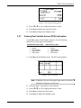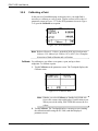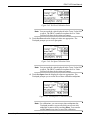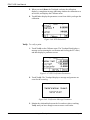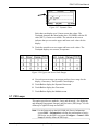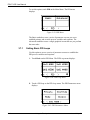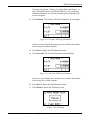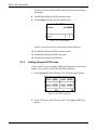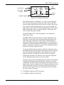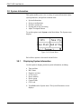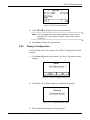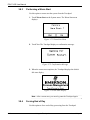
1
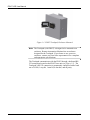
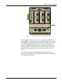
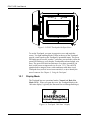
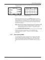
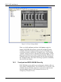
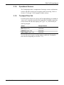
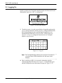
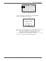
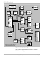
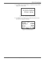
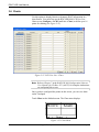
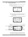
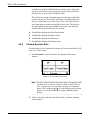
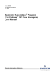
Form Number A6241 Part Number D301258X012 September 2007 FloBoss™ 107 Flow Manager LCD User Manual Remote Automation Solutions FloBoss™ 107 Flow Manager LCD Program User Manual Revision Tracking Sheet September 2007 This manual may be revised periodically to incorporate new or updated information. The revision date of each page appears at the bottom of the page opposite the page number. A change in revision date to any page also changes the date of the manual that appears on the front cover. Listed below is the revision date of each page (if applicable): Page Initial issue Revision Sep-07 NOTICE Remote Automation Solutions (“RAS”), division of Emerson Process Management shall not be liable for technical or editorial errors in this manual or omissions from this manual. RAS MAKES NO WARRANTIES, EXPRESSED OR IMPLIED, INCLUDING THE IMPLIED WARRANTIES OF MERCHANTABILITY AND FITNESS FOR A PARTICULAR PURPOSE WITH RESPECT TO THIS MANUAL AND, IN NO EVENT SHALL RAS BE LIABLE FOR ANY INCIDENTAL, PUNITIVE, SPECIAL OR CONSEQUENTIAL DAMAGES INCLUDING, BUT NOT LIMITED TO, LOSS OF PRODUCTION, LOSS OF PROFITS, LOSS OF REVENUE OR USE AND COSTS INCURRED INCLUDING WITHOUT LIMITATION FOR CAPITAL, FUEL AND POWER, AND CLAIMS OF THIRD PARTIES. Bristol, Inc., Bristol Babcock Ltd, Bristol Canada, BBI SA de CV and the Flow Computer Division are wholly owned subsidiaries of Emerson Electric Co. doing business as Remote Automation Solutions (“RAS”), a division of Emerson Process Management. FloBoss, ROCLINK, Bristol, Bristol Babcock, ControlWave, TeleFlow and Helicoid are trademarks of RAS. AMS, PlantWeb and the PlantWeb logo are marks of Emerson Electric Co. The Emerson logo is a trademark and service mark of the Emerson Electric Co. All other trademarks are property of their respective owners. The contents of this publication are presented for informational purposes only. While every effort has been made to ensure informational accuracy, they are not to be construed as warranties or guarantees, express or implied, regarding the products or services described herein or their use or applicability. RAS reserves the right to modify or improve the designs or specifications of such products at any time without notice. All sales are governed by RAS’ terms and conditions which are available upon request. RAS does not assume responsibility for the selection, use or maintenance of any product. Responsibility for proper selection, use and maintenance of any RAS product remains solely with the purchaser and end-user. © 2007 Remote Automation Solutions, division of Emerson Process Management. All rights reserved. ii Issued Sep-07 FloBoss 107 LCD User Manual Contents Chapter 1 – Introduction 1.1 1.2 1-1 Scope and Organization ................................................................................................... 1-1 Overview........................................................................................................................... 1-1 1.2.1 Display Mode...................................................................................................... 1-4 1.2.2 Power Savings Mode ......................................................................................... 1-5 1.2.3 Touchpad and ROCLINK 800 Security .............................................................. 1-6 Chapter 2 – Configuration 2.1 2.2 2.3 2.4 2.5 2.6 2-1 Configuring the Port Owner .............................................................................................. 2-1 Configuring Touchpad Options......................................................................................... 2-4 Configuring Basic List Mode (BLM).................................................................................. 2-5 Configuring Standard or Normal Mode............................................................................. 2-7 Configuring Chart Mode ................................................................................................... 2-8 Configuring Touchpad Security ........................................................................................ 2-9 Chapter 3 – Using The Touchpad 3.1 3.2 3.3 3.4 3.5 3.6 3.7 3.8 3-1 Touchpad Screens ........................................................................................................... 3-1 3.1.1 Menu Screens .................................................................................................... 3-1 3.1.2 Parameter Screens ............................................................................................ 3-2 3.1.3 Dynamic Charts.................................................................................................. 3-3 3.1.4 Operational Screens........................................................................................... 3-5 3.1.5 Touchpad Time Out............................................................................................ 3-5 Logging On ....................................................................................................................... 3-6 User Lists........................................................................................................................ 3-10 Meter Runs ..................................................................................................................... 3-12 3.4.1 Displaying Meter Information............................................................................ 3-13 3.4.2 Changing a Plate.............................................................................................. 3-14 Module Information......................................................................................................... 3-15 3.5.1 Viewing I/O and Diagnostic Information ........................................................... 3-15 3.5.2 Viewing RTD Information ................................................................................. 3-16 3.5.3 Viewing COMM Information ............................................................................. 3-17 3.5.4 Viewing Multiple Variable Sensor (MVS) Information ...................................... 3-18 3.5.5 Viewing Meter Information................................................................................ 3-19 3.5.6 Viewing System Information............................................................................. 3-20 3.5.7 Viewing Dual Variable Sensor (DVS) Information............................................ 3-21 3.5.8 Calibrating a Point ............................................................................................ 3-22 Charts ............................................................................................................................. 3-26 3.6.1 Viewing Historical Data .................................................................................... 3-27 3.6.2 Viewing Dynamic Data ..................................................................................... 3-28 PID Loops ....................................................................................................................... 3-29 3.7.1 Setting Basic PID Loops................................................................................... 3-30 3.7.2 Setting Advanced PID Loops ........................................................................... 3-32 System Information......................................................................................................... 3-34 3.8.1 Displaying System Information......................................................................... 3-34 3.8.2 Saving a Configuration ..................................................................................... 3-35 3.8.3 Performing a Warm Start.................................................................................. 3-36 3.8.4 Forcing End of Day........................................................................................... 3-36 Issued Sep-07 Contents iii FloBoss 107 LCD User Manual 3.9 3.8.5 Adjusting Touchpad Contrast ........................................................................... 3-37 Logging Off ..................................................................................................................... 3-38 Index iv I-1 Contents Issued Sep-07 FB107 LCD User Manual Chapter 1 – Introduction This chapter describes the structure of this manual and presents an overview of the Liquid Crystal Display (LCD) for the FloBoss™ 107 Flow Manager. 1.1 Scope and Organization This document serves as the user manual for the FloBoss™ 107 Flow Manager Liquid Crystal Display (LCD), which is intended for use with the FloBoss 107 Flow Manager (“FB107”). This manual describes how to install, configure, and use the FB107 LCD (the “Touchpad”). You initially access and configure the Touchpad using ROCLINK™ 800 Configuration software loaded on an IBM-compatible personal computer running Windows® 98, NT 4.0 (with Service Pack 6), 2000 (with Service Pack 2), or XP. Once configured, the Touchpad provides access to many FB107 system parameters and functions. The chapters in this manual provide information in a sequence appropriate for first-time users. Once you become familiar with the device and the procedures, the manual becomes a reference tool. This manual has the following major sections: Chapter 1 – Introduction Chapter 2 – Configuration Chapter 3 – Using the Touchpad This manual assumes that you are familiar with the FB107 and its configuration. For more information, refer to the following specification sheet and manuals: FloBoss™ 107 Flow Manager Instruction Manual (Form A6206) FloBoss™ 107 LCD Specification Sheet (5.5:LCD) ROCLINK 800 Configuration Software User Manual (for FB107) (Form A6217) 1.2 Overview The Touchpad enables you to access FB107 process and operational information and to view and change FB107 parameters. The Touchpad is a touch-sensitive liquid crystal display (LCD) screen. It fits behind a protective covering that is mounted to an enclosure (see Figure 1-1). Issued Sep-07 Introduction 1-1 FB107 LCD User Manual Figure 1-1. FB107 Touchpad, Enclosure-Mounted Note: The Touchpad (with FB107) is designed to be mounted to an enclosure. Remote Automation Solutions has an enclosure designed for the Touchpad. If you choose to use your own enclosure, contact your local sales representative for a template and appropriate specifications. The Touchpad communicates with the FB107 through a dedicated RS232 connection located on the FB107 base unit (see Figure 1-2). The Touchpad’s RS-232 connection is permanently configured with a baud rate of 19200, 1 stop bit, 1 start bit, 8 data bits, and no parity. 1-2 Introduction Issued Sep-07 FB107 LCD User Manual Display connection Figure 1-2. FB107 Base Unit, Display Connection The Touchpad is a transreflective LCD. To maintain readability in direct sunlight, it reflects most of the sunlight and increases or decreases the brightness of its display based on the amount of light. This reduces your need to manually adjust the screen. It also has a backlight to increase readability during low-light use conditions or during critical operations (such as when you enter a PIN code). During idle periods, the backlight automatically enters a power-saving mode to conserve energy. The Touchpad requires no manual calibration. Internal firmware provides the coordinates to assure display communications between the Touchpad and your FB107. Issued Sep-07 Introduction 1-3 FB107 LCD User Manual KEY ACK TOUCH SCREEN ALARM TO ACTIVATE Figure 1-3. FB107 Touchpad with Open Cover To use the Touchpad, you open its protective cover and touch the screen. Two light-emitting diodes (LEDs) at the top of the Touchpad provide visual signals on the Touchpad’s operational status. The green LED indicates successful “touches”: each time you touch the screen, the green LED flashes to verify that the Touchpad has acknowledged your entry. The green LED also can flash once every three seconds if you have set the power savings mode (see Section 1.2.2). The red LED signals alarm or integrity issues, and coordinates with other visual Touchpad clues (such as an on-screen asterisk, i, or a) to identify the area of concern. See Chapter 3, Using the Touchpad. 1.2.1 Display Mode The Touchpad has two operational modes, Normal and Basic List Mode (BLM). When you open the cover, the Touchpad displays the “idle state display” (typically the Emerson Process Management logo): Figure 1-4. Touchpad “Idle State” Display 1-4 Introduction Issued Sep-07 FB107 LCD User Manual When you touch the screen, you see either a list of system parameters or a number grid. Figure 1-5. Initial Active Touchpad Displays BLM mode (indicated by the on-screen BLM List label) provides an auto-scrolling list of read-only parameters, which displays up to 32 userdefined parameters (refreshed once per second) without requiring a log on process. (At any time you can interrupt the auto-display and log on through the Touchpad.) Note: BLM mode also includes a dynamic chart mode. Technicians can touch a parameter and the Touchpad displays a dynamic chart related to that parameter. See Chapter 3, Using the Touchpad, for further details on this feature. Normal mode requires a sign-in process before displaying any information. Refer to Chapter 3, Using the Touchpad, for further information. 1.2.2 Power Savings Mode The Touchpad also provides an optional power-savings mode, which activates whenever the idle state display occurs. (This power savings mode works with either Normal or BLM display mode.) Select this option on the Advanced tab of the LCD Controller screen (see Figure 16). Issued Sep-07 Introduction 1-5 FB107 LCD User Manual Figure 1-6. Power Savings Modes When you click Low Power (and then click Update to apply the change), ROCLINK 800 performs a warm start and shuts down the Touchpad. While the Touchpad is blank, the green LED blinks once every three seconds to indicate the Touchpad is active. The Touchpad “awakens” when you touch it, and shows the idle state display. At that point log on and proceed to use the Touchpad normally. Whenever the Touchpad “times out” and would normally show the idle state display, the Touchpad is blank. This reduces the energy required to continually show the idle state display. 1.2.3 Touchpad and ROCLINK 800 Security ROCLINK 800 security enables you can determine which user IDs can access which Touchpad features. You can define up to 16 user IDs, each of which can have read-only, read-write, or no access to the four user lists and standard features of the Touchpad. See Section 2.6, Configuring Touchpad Security. 1-6 Introduction Issued Sep-07 FB107 LCD User Manual Chapter 2 – Configuration This chapter provides instructions for configuring Touchpad options. The FB107 is factory-configured to accept the Touchpad. Until you connect the Touchpad to the FB107, the Display port displays an integrity (“red I”) error (see Figure 2-1, Section 2-1). After connecting the Touchpad, you can configure additional display options as well as Touchpad security (see Sections 2-2 through 2-6). 2.1 Configuring the Port Owner 1. Log onto and open ROCLINK 800. The FB107 graphic displays. Figure 2-1. FB107 Graphic Display 2. Plug the connector for the Touchpad into the Display port on your FB107 (see Figure 2-1). The Touchpad activates and displays the message “Waiting for Comms…” Issued Sep-07 Configuration 2-1 FB107 LCD User Manual Figure 2-2. Touchpad Activation 3. Click the Display port on the FB107 graphic. The LCD Controller screen appears at the bottom of the FB107 graphic display. Note that the FB107 graphic highlights the Display port and removes the integrity error on the display port. Figure 2-3. LCD Controller 4. Select the Advanced tab. The Advanced screen displays. 2-2 Configuration Issued Sep-07 FB107 LCD User Manual Figure 2-4. LCD Controller, Advanced tab 5. Verify that LCD Master in the Port Owner frame is the port owner (this is the default value). Note: Figure 2-4 also shows the other default comm values (Baud Rate, Parity, Data Bits, Stop Bits, and LCD Mode) for the FB107. 6. Click Apply if you changed any values on this screen. ROCLINK 800 performs a warm start, and the Touchpad displays the Emerson Process Management logos. Figure 2-5. Emerson Process Management Logos Proceed to Sections 2.2 through 2.6 to configure display options. Issued Sep-07 Configuration 2-3 FB107 LCD User Manual 2.2 Configuring Touchpad Options When configuring Touchpad options, you determine both the default display mode (Sections 2.3 through 2.5) and which user IDs may access which Touchpad features (Section 2.6). You use the Configure option on the ROCLINK menu bar to select one of two possible default display modes for the Touchpad. Figure 2-6. ROCLINK 800 LCD User List Configuration Options Option Description Standard Requires you to first log onto the Touchpad. Displays (based on pre-defined ROCLINK 800 security parameters) select system values and allows you modify select system parameters. Note: This is also called “Normal” mode. BLM Automatically displays up to 32 parameter values. Allows you (based on pre-defined ROCLINK 800 security parameters) to log onto the Touchpad and display select system values and modify select system parameters. Chart Requires you to first log onto the Touchpad. Displays, in a chart recorder format, historical or dynamic values for up to 16 user-defined parameters. Note: For convenience, a dynamic charting function is available for the parameters displayed in basic list mode. However, this is not the fullfunction charting facility. 2-4 Configuration Issued Sep-07 FB107 LCD User Manual 2.3 Configuring Basic List Mode (BLM) In Basic List Mode (BLM), the Touchpad displays up to 32 parameter values, automatically scrolling through the list at a speed you define. (The Touchpad displays up to two parameters per screen.) This mode allows service technicians to quickly review a dynamic display of current values without logging onto the Touchpad. 1. Select the Advanced tab of the LCD Controller screen. The Advanced screen displays. Figure 2-7. ROCLINK 800 LCD User List Configuration Options 2. Select BLM in the LCD Mode frame. Click Apply to save your change. ROCLINK 800 performs a warm start. 3. Select Configure > LCD User List > BLM from the ROCLINK 800 Menu bar. The LCD User List – BLM screen displays. Issued Sep-07 Configuration 2-5 FB107 LCD User Manual Figure 2-8. LCD User List – BLM 4. Complete the following fields to define the contents of the BLM list. Field Description Title Sets a 10-character alphanumeric identifier for the list. Scroll Time Indicates the number of seconds the Touchpad displays each parameter set before scrolling to the next parameter set. (The Touchpad displays up to two parameters at a time.) Valid values are 0 (do not scroll) to 255; the default is 4. Note: If you set this value to 0, you must use the Ï and Ð keys on the Touchpad to manually scroll through the parameters defined in the list. Device Parameter Sets the parameter that you want to display on the Touchpad. Click … to display a Select TLP screen you use to define the parameter. Text Sets a 10-character alphanumeric identifier for the parameter. Units Shows the engineering units for the associated parameter. 5. Click the 17-32 tab to define 16 additional parameters. 2-6 Configuration Issued Sep-07 FB107 LCD User Manual 6. Click Apply if you make any changes to this screen. 7. Click OK to close the LCD User List – BLM screen. 8. Proceed to Chapter 3, Using the Touchpad. 2.4 Configuring Standard or Normal Mode In Standard or Normal mode, the Touchpad displays the Emerson Process Management logos. When you touch the screen, a logon grid displays. You then enter a PIN number to log on to the Touchpad. 1. Select the Advanced tab of the LCD Controller screen. The Advanced screen displays. Figure 2-9. ROCLINK 800 LCD User List Configuration Options, Advanced tab 2. Verify that Normal is selected in the LCD Mode frame. (This is the factory default value for the Touchpad.) 3. Click Apply if you have needed to change the setting. ROCLINK 800 performs a warm start. The Touchpad now starts in Normal mode. Issued Sep-07 Configuration 2-7 FB107 LCD User Manual 4. Proceed to Chapter 3, Using the Touchpad. 2.5 Configuring Chart Mode Chart mode allows the Touchpad to emulate a chart recorder. After you log on normally, Chart is one of the options displayed on the Main Menu: Figure 2-10. Touchpad Main Menu The Touchpad can display up to 16 historic or dynamic system values. Use this procedure to define the displayed values. 1. Select Configure > LCD User List > Chart from the ROCLINK 800 Menu bar. The LCD User List – Chart screen displays. Figure 2-11. LCD User List - Chart 2-8 Configuration Issued Sep-07 FB107 LCD User Manual 2. Complete the following fields to define the chart display values. Field Description Data Source Sets the source for data included in the chart. Valid values are: Standard History Sets a standard history point to chart. Click … to open a Select History Point dialog box you can use to select a valid standard history point. Extended History Sets an extended history point to chart. Click … to open a Select History Point dialog box you can use to select a valid extended history point. Dynamic Sets a dynamic data point to chart. Click … to open a Select TLP dialog box you can use to select a valid TLP. Data Point Shows the data point selected. Text Sets a 10-character alphanumeric identifier for the data point. Units Shows the engineering units for the associated parameter. Scaling Indicates whether the system applies automatic or manual value limit factors to the charted results. Valid values are Auto (apply automatic values) or Manual (apply defined values). HighScale Sets the high value for the data point. Note: This field is available only if you select Manual as a scaling option. Low Scale Sets the low value for the data point. Note: This field is available only if you select Manual as a scaling option. 3. Click Apply if you make any changes to this screen. 4. Click OK to close the LCD User List – Chart screen. 5. Proceed to Chapter 3, Using the Touchpad. 2.6 Configuring Touchpad Security Touchpad security enables you to selectively restrict or permit access to Touchpad functions for up to 16 user IDs you define. To do this, you use ROCLINK 800’s Device Security screens (Figures 2-12 and 2-13). You can define an ID which can access all or only one user list or just the Touchpad’s “standard lists.” Additionally, the ID can have edit capability or just view capability. You define IDs and their accesses to meet your organization’s needs. Issued Sep-07 Configuration 2-9 FB107 LCD User Manual 1. Select ROC > Security from the ROCLINK 800 Menu bar. The Device Security screen displays. Figure 2-12. Device Security Note: Use only the left-hand side of this screen to define Touchpad security. The right-hand fields (Security on LOI, Security on COM1, etc.) do not apply to the Touchpad (but do apply to security levels on the FB107). Leave the Security on LCD field disabled. It applies only if you are connecting a display other than the LCD from Remote Automation Solutions. If that is the case, contact Product Support. 2. Click in the first empty Operator ID field. The Device Security dialog box displays. 2-10 Configuration Issued Sep-07 FB107 LCD User Manual Figure 2-13. Device Security, User Level 3. Complete the following fields to define the access permissions for the new user ID. Field Description Operator ID Sets the three alphanumeric characters for the password. Password Sets the four-digit password associated with this ID. Confirm Password Confirms the four-digit password associated with this ID. Note: The contents of this field must match the contents of the Password field. Access Level This field does not apply to the FB107 Touchpad. User List 1 through 4 Indicates whether the ID can access the userdefined User Lists. Valid values are: Standard Lists Issued Sep-07 Disabled Removes the user list from the displayed options. View Only Displays the user list but does not allow edits to displayed data. View+Edit Displays the user list and allows edits to displayed data. Indicates whether the ID can access the standard Touchpad functions (that is, the options on the Main Menu screen: Meter Runs, Modules, Charts, PID, System, and Log Off). Valid values are: Disabled Removes the user list from the displayed options. View Only Displays the user list but does not allow edits to displayed data. View+Edit Displays the user list and allows edits to displayed data. Configuration 2-11 FB107 LCD User Manual 4. Click OK to apply these edits. The system displays the updated Device Security screen. Figure 2-14. Device Security 5. Repeat steps 2 and 3 to add up to 14 more IDs. 6. Click OK to display the FB107 graphic. 2-12 Configuration Issued Sep-07 FB107 LCD User Manual Chapter 3 – Using The Touchpad This chapter describes the day-to-day use of the Touchpad. 3.1 Touchpad Screens The Touchpad uses several major screen formats to present information. Included are menu screens, parameter screens, and dynamic charts. Note: System security settings controls which options display on your Touchpad and whether you can edit parameter values. Refer to Section 2.6, Configuring Touchpad Security, for further information. 3.1.1 Menu Screens Menu screens are basically two or more options placed in a grid. Typically, an Exit option may appear in the menu’s lower left corner. A menu label (such as Main Menu or Slot #0 in Figure 3-1) is centered between brackets, and arrows (to access additional menu options) may appear in the right corner of the menu. Figure 3-1 shows two examples of menu screens. Figure 3-1. Sample Menu Screens Touching an option on the menu screen’s grid may lead to another menu or to a parameter screen. Notes: Issued Sep-07 A blinking asterisk (*) in the upper right corner of a menu box (as in the Modules option in Figure 3-1) indicates an integrity or alarm issue in this module. A blinking i, ia, or a in the upper right corner of a menu box (as in AI 2 and AO 1 in Figure 3-1) indicates an integrity or alarm issue with this point. Using the Touchpad 3-1 FB107 LCD User Manual 3.1.2 Parameter Screens Parameter screens primarily display values, but provide other ways to display information. A label typically appears at the top of a parameter screen indicating where that parameter belongs. The bottom of the screen contains two or more boxes, usually providing an Exit option on the lefthand side, a Hold option (to prevent the screen from auto-scrolling to the next set of parameters) in the center, and Ï and Ð options on the righthand side so you can move more quickly from parameter to parameter (see Figure 3-2). Figure 3-2. Sample Parameter Screens Up to two parameter values display in the center of the screen. The values are dynamic and refresh each second. Parameter value (read-only) Parameter tag or label Parameter units Parameter value (editable) Figure 3-3. Sample Parameter Screen Parameter values are usually read-only. However, you can edit a value in a box (as in the case of 534.57 in Figure 3-3). Touch the box to display a numeric keypad screen (Figure 3-4). Figure 3-4. Numeric Keypad 3-2 Using the Touchpad Issued Sep-07 FB107 LCD User Manual As you enter a new value, the numeric keypad changes (as shown in Figure 3-4). When you are finished, touch Done. The Touchpad displays a screen to confirm the new value (see Figure 3-5). Figure 3-5. Edited Parameter When you touch Yes, the new value appears in the parameter screen’s editable field. Figure 3-6. Edited Parameter Note: The Touchpad uses this “value inside a box” signal extensively to indicate a field you can edit. Finally, you can touch the parameter tag on any parameter screen to display a chart screen that dynamically displays the values of that parameter (see Section 3.1.3). 3.1.3 Dynamic Charts The Touchpad can display any parameter you select in a dynamic “chart recorder” format. Touch the label or units on a parameter screen to display the chart. Charting begins from the moment of touch and continues either for 30 minutes or until you touch Exit. Issued Sep-07 Using the Touchpad 3-3 FB107 LCD User Manual Current upper and lower scale Current date and time Figure 3-7. Sample Dynamic Chart The parameter label displays in the upper center of the screen, and alternates with a display of the units every four seconds. The current parameter value displays in the lower center of the screen. The current date appear in the upper right-hand corner of the screen. The current time appears in the lower right-hand corner of the screen. The values in the upper and lower left-hand corners of the screen display the chart’s current scale. You can modify the scale by touching the asterisk (*) just below the upper scale value. The Touchpad displays a numeric keypad you use to define first a new upper range, then a new lower range. Figure 3-8. Chart Scale Ranges When you exit the numeric keypads, the parameter screen reflects the new values. Figure 3-9. Revised Scales Note: These new values are valid only for the current viewing. The Touchpad restores the original scale values when you exit the parameter screen. 3-4 Using the Touchpad Issued Sep-07 FB107 LCD User Manual 3.1.4 Operational Screens The Touchpad provides a complement of message screens, confirmation screens, and other screen types to support system processing. Refer to Sections 3.2 through 3.9 for examples of these screens. 3.1.5 Touchpad Time Out For both security and to save power, the Touchpad display goes blank (or “times out”) at specific intervals if left untouched. Touching a timed-out screen restores the idle state display (see Figure 1-4), from which you must log on again. Screen Display Duration PIN (Figure 3-12) 1 minute Menu (Figure 3-1) 10 minutes Calibrate (Figure 3-43) 60 minutes Plate Change (Figure 3-42) 30 minutes You can also access a power savings mode to enable the Touchpad to time out more frequently (see Section 1.2.2). Issued Sep-07 Using the Touchpad 3-5 FB107 LCD User Manual 3.2 Logging On In daily operation, the Touchpad normally displays the Emerson Process Management logo in its “idle” or waiting state. Figure 3-10. Idle State Display 1. Touch the screen. A second screen displays, depending on the mode you’ve selected (Normal or BLM). If you’ve configured BLM mode, the Touchpad begins to auto-scroll through the parameters you defined on ROCLINK 800’s LCD User List – BLM screen (see Section 2.3. If you’ve configured Normal mode, the Touchpad displays a log on screen: Figure 3-11. Log On Note: The Touchpad displays this log on screen for 60 seconds. If you do not enter a PIN in that time, the idle state screen displays. 2. Enter a valid log on PIN. As you touch each number, the Key Acknowledgement LED (Key Ack, Figure 1-3) should blink green and the Touchpad reverses the numeric image (see Figure 3-12). 3-6 Using the Touchpad Issued Sep-07 FB107 LCD User Manual Figure 3-12. Touched Value If you enter an incorrect PIN number, the Touchpad displays a message. Click OK and re-enter the PIN. Figure 3-13. Invalid PIN Message Note: The default PIN is 1000. If you have disabled that PIN or replaced it with another PIN to establish security for your organization, use those values with the Touchpad. Figure 3-14 provides a map of all Touchpad options. Issued Sep-07 Using the Touchpad 3-7 FB107 LCD User Manual Figure 3-14. Touchpad Options Map Once you enter a valid PIN on the log on screen, the Touchpad’s Main Menu screen displays: 3-8 Using the Touchpad Issued Sep-07 FB107 LCD User Manual Figure 3-15. Touchpad Main Menu Option Description User Lists Displays a list of 16 parameter values. You can define up to four lists, for a total of up to 64 parameters. Note: Configure these values using the LCD User List screen. Meter Runs Displays values for up to four meter runs. Note: These are read-only values. You configure the number of valid meters on the Points tab on the Device Information screen (ROC > Device Information) and the meter content itself on the Meter Setup screen (Meter > Setup). Modules Displays parameter values associated with each module installed in the FB107. Chart Displays historical or dynamic information in a chart format. Note: These are read-only values. You define the format, scale, and content of the charts using the LCD User List – Chart screen (Configure > LCD User List > Chart). PID Displays and permits changes to defined PID parameters. . Note: You must first define PID parameters on the PID Loop screen (Configure > Control > PID Loop). System Enables you to access and modify some general system parameters. Log Off Logs you off the Touchpad; redisplays the idle logos screen. Sections 3.3 through 3.9 discuss these options. Issued Sep-07 Using the Touchpad 3-9 FB107 LCD User Manual 3.3 User Lists User lists are groups of up to 16 system parameters. You can define up to four user lists, for a total of 64 parameters. You first define the user lists in ROCLINK 800 and update your ROCLINK 800 configuration file. When you next log onto the Touchpad, the User List menu option reflects those changes. Alternately, you can log off the Touchpad and log back on to see your changes. To define user lists: 1. Select Configure > LCD User List > Standard on the ROCLINK 800 menu bar. The LCD User List screen displays. Figure 3-16. LCD User List 2. Complete the following fields to define the contents of each user list. 3-10 Field Description List No. Sets the number of the LCD User List you want to configure. Click d to display all defined lists. You can define up to four user lists. Title Sets a 10-character alphanumeric identifier for the user list. Using the Touchpad Issued Sep-07 FB107 LCD User Manual Field Description Scroll Time Indicates the number of seconds the Touchpad displays each parameter set before scrolling to the next parameter set. (Typically the Touchpad displays two parameters at a time.) Valid values are 0 (do not scroll) to 255. Note: If you set this value to 0, you must use the Ï and Ð keys on the Touchpad to manually scroll through the parameters defined in the list. Device Parameter Sets the parameter that you want to display on the Touchpad. Click … to display a Select TLP screen you can use to define the parameter. Text Sets a 10-character alphanumeric identifier for the parameter. Units Shows the engineering units for the associated parameter. 3. Click Apply if you make any changes to this screen. To define additional lists, repeat step 2. 4. Click OK to close the LCD User List screen. Once you have defined your user lists and sent the changes to the Touchpad, you can view them on the Touchpad and, if appropriate, edit the values. Note: These steps assume you have successfully logged onto the Touchpad and are starting at the Main Menu. 1. Touch User Lists on the Touchpad. The User List menu displays. Figure 3-17. User List Menu 2. Touch the number of a User List. A parameters screen displays. Issued Sep-07 Using the Touchpad 3-11 FB107 LCD User Manual Figure 3-18. User List Parameters) 3. The Touchpad automatically scrolls through the defined values in the user list. You can touch Hold to pause the display (and restart the scroll by pressing Scroll), or touch Ð or Ï to move more quickly through the parameter values. In this example, note that the value for the second parameter (Pid 1 SetPt) has a box around it. This means you can edit it. If you touch this value, a numeric keypad screen displays. Figure 3-19. Numeric Keypad If appropriate, use the keypad to enter a new value for the indicated field. Touch Done to apply the edited value to the parameters screen.The Touchpad requires your confirmation before it applies any changes to the parameter values. 4. Touch Exit to display the User List menu. 5. Touch Exit to display the Touchpad Main Menu. 3.4 Meter Runs You can define up to four meter runs for the FB107. You configure the number of valid meters on the Points tab on the Device Information screen (ROC > Device Information) and the meter information itself on the Meter Setup screen (Meter > Setup). Once you have defined and configured the meter runs using ROCLINK 800, you can use the Touchpad to view and change the information. 1. Touch Meter Runs on the Main Menu. The Meter Run menu displays. 3-12 Using the Touchpad Issued Sep-07 FB107 LCD User Manual Figure 3-20. Meter Run Menu 2. Touch a meter run. An option screen displays. Note that the selected meter displays at the bottom of the screen. Figure 3-21. Meter Menu Note: In this example, Well #100 is defined as using an orifice meter. The Plate Chg option displays only for orifice meters. For turbine meters, you see only the Values option. 3.4.1 Displaying Meter Information Use this option to display meter information. 1. Touch Values on the Meter Run menu. The meter-specific parameters screen displays. Figure 3-22. Meter Parameters 2. Touch Ð or Ï to scroll through a number of meter-specific parameters, including: Issued Sep-07 Differential pressure (orifice meters only) Uncorrected flow (turbine meters only) Using the Touchpad 3-13 FB107 LCD User Manual Static pressure Temperature Flowrate Energy rate Flow today Energy today Alarms 3. Touch Exit to display the Meter Run menu. 3.4.2 Changing a Plate Note: This option is available only for orifice meters. Although you can also accomplish this process using the Plate Change screen in ROCLINK 800 (Meter > Plate Change), the Touchpad provides this function as a convenience for service technicians who may need to change orifice plates without access to ROCLINK 800. 1. Touch Plate Chg on the Meter Run menu. The Plate Change Menu displays. Figure 3-23. Plate Change Menu 2. Touch the condition under which the plate change occurs. Note: If you select Flowing, the system freezes input values for the duration of the change to provide constant values to the flow calculations and displays a notification screen. When you exit this activity, the system restores the meter values. 3. The system then displays three parameter values screens. Figure 3-24. Plate Change Parameters 3-14 Using the Touchpad Issued Sep-07 FB107 LCD User Manual Note: You can edit the orifice diameter value. These parameter screens remain active for 30 minutes, after which the Touchpad displays the idle state screen. 4. Touch Exit to display the Plate Change menu screen. 5. Touch Exit to display the Meter menu. 6. Touch Exit to display the Meter Run menu. 3.5 Module Information Use this option to view information for each module installed in the FB107. The Modules menu shows only the modules you have installed on your FB107. For example, Figure 3-25 shows a fully equipped FB107 with expansion plate. If your FB107 has an open module slot, the Touchpad shows the slot number but does not include a module identifier. If your FB107 does not have an expansion plate, the Touchpad displays the second row (slots 4 through 7) but omits the numbers, indicating those slots are not available. You can also use this menu to display information on meter runs (refer to Section 3.5.5, Viewing Meter Information) and to diagnose alarm conditions (refer to Section 3.5.8, Calibrating a Point). 3.5.1 Viewing I/O and Diagnostic Information 1. Touch Modules on the Main Menu. The Modules menu displays. Figure 3-25. Modules Menu Notes: Issued Sep-07 A blinking asterisk (*) in the upper right corner of a module box (as in slots 0 and 3 in Figure 3-25) indicates an integrity or alarm issue in this module. This mirrors a blinking asterisk that may appear in the upper right corner of the Modules option on the Main Menu. The content of the Modules menu corresponds to your installed system. The example in Figure 3-25 shows a fully loaded FB107. Using the Touchpad 3-15 FB107 LCD User Manual 2. Touch a module. The Touchpad displays a screen showing all the I/O points defined for that module (Figure 3-26 shows the options for the CPU module). Figure 3-26. Module I/O Points Note: A blinking i, ia, or a in the upper right corner of a point box (as in AI 2 and AO 1 in Figure 3-26) indicates an integrity or alarm issue with this point. 3. Touch an I/O point. The Touchpad displays a series of screens showing the parameters for that point. Figure 3-27. I/O Point Parameters Note: The Touchpad places a box around any parameter value you can edit (as with AO or DO points). See Figure 3-18. 4. Review the points. To resolve an error condition (if one exists), use ROCLINK 800 to correct the situation. 5. Touch Exit to display the Module I/O Points screen. 6. Touch Exit to display the Modules Menu screen. 3.5.2 Viewing RTD Information Use this option to review data on the CPU module’s Resistance Temperature Detector (RTD). 1. Touch Modules on the Main Menu. The Modules menu displays. 3-16 Using the Touchpad Issued Sep-07 FB107 LCD User Manual Figure 3-28. Modules Menu 2. Touch Cpu. An I/O points screen for the CPU module displays. Figure 3-29. Module I/O Points 3. Touch RTD. A parameter screen for the RTD module displays. Figure 3-30. RTD Parameters 4. Touch Ð or Ï to view additional RTD parameter values. 5. Touch Exit to display the Module I/O Points screen. 6. Touch Exit to display the Module menu. 3.5.3 Viewing COMM Information Your FB107 can have up to two communications modules (RS-232 or RS-485) which you must place in slots 1 or 2. Use this procedure to verify the status of these modules. 1. Touch Modules on the Main Menu. The Modules menu displays. Issued Sep-07 Using the Touchpad 3-17 FB107 LCD User Manual Figure 3-31. Modules Menu 2. Touch rs232 or rs485 (depending on which communications module you have installed). A status screen displays. Figure 3-32. Communication Status 3. Touch OK to display the Modules menu. 3.5.4 Viewing Multiple Variable Sensor (MVS) Information The FB107 supports up to six MVS transmitters. Use this option to review the parameters for each transmitter. 1. Touch Modules on the Main Menu. The Modules menu displays. Figure 3-33. Modules Menu 2. Touch Mvs. The MVS menu displays. 3-18 Using the Touchpad Issued Sep-07 FB107 LCD User Manual Figure 3-34. MVS Menu Note: A blinking i, ia, or a in the upper right corner of an MVS box (as in Mvs-1 and Mvs-3 in Figure 3-34) indicates an integrity or alarm issue with this transmitter. 3. Touch a transmitter box. A parameter screen for the MVS transmitter displays. Figure 3-35. MVS Parameters 4. Touch Ð or Ï to view additional parameter values. 5. Touch Exit to display the MVS menu. 6. Touch Exit to display the Modules menu. 3.5.5 Viewing Meter Information The FB107 supports up to four meters. Use this option to view flow rate and alarm information for each defined meter run. 1. Touch Meter on the Modules menu. The Meter Run menu displays. Figure 3-36. Meter Run Menu Issued Sep-07 Using the Touchpad 3-19 FB107 LCD User Manual Note: A blinking a in the upper right corner of a run box (as in Run 2 in Figure 3-36) indicates an active alarm. 2. Touch a meter run. A parameter screen for the meter run displays. Figure 3-37. Meter Run Parameters 3. Touch Exit to display the Meter Run menu. 4. Touch Exit to display the Modules menu. 3.5.6 Viewing System Information Use the SysAI option on the Modules menu to view the following information on the FB107’s battery, charging status, and board temperature. Battery Volts Alarms Low Volts High Volts A/D Counts Charging Volts Alarms Low Volts High Volts A/D Counts Board Temperature Degrees Alarms Low Degrees High Degrees A/D Counts 1. Touch SysAi on the Modules menu. The System AI menu displays. Figure 3-38. System AI Menu 2. Touch an option. A parameters screen displays. 3-20 Using the Touchpad Issued Sep-07 FB107 LCD User Manual Figure 3-39. System AI Parameters 3. Touch Ð or Ï to view additional parameter values. 4. Touch Exit to display the System AI menu. 5. Touch Exit to display the Modules menu. 3.5.7 Viewing Dual Variable Sensor (DVS) Information Use the Dvs option on the Modules menu to view the following differential or static pressure information: Differential Pressure (DP) Current Pressure Alarms Low Pressure High Pressure A/D Counts Static Pressure (SP) Current Pressure Alarms Low Pressure High Pressure A/D Counts 1. Touch Dvs on the Modules menu. The DVS menu displays. Figure 3-40. DVS Menu Note: A blinking i, ia, or a in the upper right corner of a run box indicates an integrity or alarm issue. 2. Touch an option. A parameters screen displays. 3. Touch Ð or Ï to view additional parameter values. 4. Touch Exit to display the DVS menu. 5. Touch Exit to display the Modules menu. Issued Sep-07 Using the Touchpad 3-21 FB107 LCD User Manual 3.5.8 Calibrating a Point In the process of troubleshooting an integrity error, you might find it necessary to calibrate or verify a point. Various screens (such as the AI parameter screen in Figure 3-27 or the RTD parameter screen in Figure 3-41) provide Calibrate as an option. Figure 3-41. RTD Parameters Note: Refer to Chapter 8, Utilities, in the ROCLINK 800 Configuration Software User Manual (for FloBoss 107) (A6217) for a complete discussion of both calibration and verification. Calibrate For calibration, you define a zero point, a span, and up to three midpoints. To calibrate a point: 1. Touch Calibrate on the parameter screen. The Touchpad displays the Calibrate menu. Figure 3-42. Calibrate Menu Note: Whether you select Calibrate or Verify, ROCLINK 800 freezes the current value and displays a notification screen. When you exit the utility, ROCLINK 800 restores the live values. 2. Touch Calibrate. The Touchpad displays a message screen (starting the calibration and freezing the EU value) and then displays a parameter screen. 3-22 Using the Touchpad Issued Sep-07 FB107 LCD User Manual Figure 3-43. Set Zero Calibration Point Note: You can touch the value displayed in the Tester Value field to edit it. The FB107 continues to update the Live Value field and calculate the deviation percentage. 3. Touch Set Zero when the displayed values are appropriate. The Touchpad prompts you to set a span point. Figure 3-44. Set Span Calibration Point Note: You can touch the value displayed in the Tester Value field to edit it. The FB107 continues to update the Live Value field and calculate the deviation percentage. 4. Touch Set Span when the displayed values are appropriate. The Touchpad prompts you to set the first of three calibration midpoints. Figure 3-45. Set Midpoint 1 Calibration Point Note: For calibrations, you can set up to three midpoints (the Touchpad presents a screen on which you can set each midpoint) or none at all by touching Done. You can also touch Cancel at any time to cancel the calibration. Issued Sep-07 Using the Touchpad 3-23 FB107 LCD User Manual 5. When you touch Done, the Touchpad evaluates the calibration, displays a completion message indicating whether the calibration was successful, and displays the Calibrate menu. 6. Touch Exit to display the parameter screen from which you began the calibration. Figure 3-46. RTD Parameters Verify To verify a point: 1. Touch Verify on the Calibrate menu. The Touchpad first displays a message screen (starting the verification and freezing the EU value) and then displays a parameter screen. Figure 3-47. RTD Verification Parameters 2. Touch Verify. The Touchpad displays a message and generates an event for the event log. Figure 3-48. Verification Message Parameters 3. Monitor the relationship between the live and test values, touching Verify until you have enough events to ensure verification. 3-24 Using the Touchpad Issued Sep-07 FB107 LCD User Manual 4. Touch Done. The Touchpad displays a completion message and then displays the Calibrate menu Figure 3-49. Verification Message Parameters 5. Touch Exit on the Calibrate menu to display the parameter screen from which you began the calibration. Figure 3-50. RTD Parameters Issued Sep-07 Using the Touchpad 3-25 FB107 LCD User Manual 3.6 Charts Use this option to display historic or dynamic FB107 information in a chart format. You must first use the ROCLINK 800 LCD User List – Chart screen (Configure > LCD User List > Chart) to define up to 16 points for charting (see Figure 3-51). Figure 3-51. LCD User List – Chart Note: Refer to Chapter 7 in the ROCLINK 800 Configuration Software User Manual (for FloBoss 107) (A6217) for complete instructions on configuring this screen. Once you have configured the points on this screen, you can view them on the Touchpad. Touch Chart on the Modules menu. The Chart menu displays. Figure 3-52. Chart Menu 3-26 Using the Touchpad Issued Sep-07 FB107 LCD User Manual 3.6.1 Viewing Historical Data Use this option to view defined historical data points you have defined on the LCD User List – Chart screen. 1. Touch Historic on the Chart menu. The History menu displays. Figure 3-53. History Menu Note: This menu enables you to view historical data either on an hourly or daily basis. The menu options on the subsequent screens are the same. 2. Touch Daily on the History menu. The Daily History menu displays. Figure 3-54. Daily History Menu 3. Touch an option on the Daily History menu. A history charting screen displays. MM/DD at scroll point Upper scale Value’s label Value at current scroll point Time at scroll point Lower scale Figure 3-55. History Chart The vertical dotted line indicates the current point on the historical record. The arrows on the right side of the chart allow you to scroll forward (X) or backward (W) on the historical record (up to 60 days, Issued Sep-07 Using the Touchpad 3-27 FB107 LCD User Manual as defined on the ROCLINK 800 History Setup screen’s Setup tab). Touch an arrow once to move in daily (or hourly) steps; touch and hold an arrow to “fast scroll” through the chart. The date for the current scroll point appears in the upper right-hand corner of the screen. The time for the current scroll point appears in the lower right-hand corner of the screen. The value for the current scroll point appears in the lower middle of the screen. The label for the value appears in the upper middle of the screen, and alternates with the units for that label every four seconds. 4. Touch Exit to display the Daily History menu. 5. Touch Exit to display the History menu. 6. Touch Exit to display the Chart menu. 7. Touch Exit to display the Modules menu. 3.6.2 Viewing Dynamic Data Use this option to view dynamic data points you have defined on the LCD User List – Chart screen. 1. Touch Dynamic on the Chart menu. The Dynamic Data menu displays. Figure 3-56. Dynamic Data Menu Note: The titles on the Dynamic Data menu items correspond to what you have used–or entered–in the Text field on the LCD User List – Chart screen. You can define as many as 16 Dynamic points. The Touchpad configures each defined point as a menu option. You can touch Ð or Ï to display additional menu options. 2. Touch a selection on the Dynamic Data menu. A dynamic charting screen displays. 3-28 Using the Touchpad Issued Sep-07 FB107 LCD User Manual Figure 3-57. Dynamic Chart Each chart can display up to 54 most recent data values. The Touchpad alternates the chart header (here, FLOWHR) with the EU value (MCF), if units are available. The asterisk on the screen indicates that you can set the upper and lower scale values for the display. 3. Touch the asterisk to set new upper and lower scale values. The Touchpad displays two screens, in sequence. Figure 3-58. Upper and Lower Scale Ranges 4. Use each screen to enter a new upper and new lower range for the display, if necessary. The Dynamic Chart displays. 5. Touch Exit to display the Dynamic Data menu. 6. Touch Exit to display the Chart menu. 7. Touch Exit to display the Modules menu. 3.7 PID Loops This option provides two methods—basic and advanced—for displaying and changing Proportional, Integral, and Derivative (PID) loops. You can define up to eight PID loops on an FB107. Note: Use the Points tab on the ROCLINK 800 Device Information screen (ROC > Information) to define the total number of active PID loops; use the PID Loop screen (Configure > Control > PID Loop) to initially define the PID loops. Issued Sep-07 Using the Touchpad 3-29 FB107 LCD User Manual To use this option, touch PID on the Main Menu. The PID menu displays. Figure 3-59. PID Menu The Basic method accesses a series of parameter screens you use to establish primary and override process variables and setpoints. The Advanced method accesses a single graphical screen that use you perform the same tasks. 3.7.1 Setting Basic PID Loops Use this option to access a series of parameter screens to establish the PID process variables and setpoints. 1. Touch Basic on the PID Menu. The PID Loop menu displays. Figure 3-60. PID Loop Menu 2. Touch a PID loop on the PID Loop menu. The PID Parameters menu displays. Figure 3-61. PID Parameters Menu 3-30 Using the Touchpad Issued Sep-07 FB107 LCD User Manual Use these four options – Primary, Override, Mode, and Output – to refine PID parameters for each defined PID loop. You can modify individual parameters or (as in this example) proceed through each screen in sequence. 3. Touch Primary. The Primary PID Loop Parameters screen displays. Figure 3-62. Primary PID Loop Parameters Use this screen to display the primary process variable and redefine (if necessary) the primary setpoint. 4. Touch Exit to display the PID Parameters menu. 5. Touch Override. The Override Parameters screen displays. Figure 3-63. Override PID Loop Parameters Use this screen to display the override process variable and redefine (if necessary) the override setpoint. 6. Touch Exit to display the PID Parameters menu. 7. Touch Mode to display the PID Mode screen. Figure 3-64. PID Mode Issued Sep-07 Using the Touchpad 3-31 FB107 LCD User Manual Use this screen to switch the PID Control mode between Automatic and Manual. 8. Touch Exit to display the PID Parameters menu. 9. Touch Output to display the PID Output screen. Figure 3-65. PID Output Use this screen to review the current output for the PID loop. 10. Touch Exit to display the PID Parameters menu. 11. Touch Exit to display the PID Loop menu. 12. Touch Exit to display the PID Menu. 3.7.2 Setting Advanced PID Loops Use this option to access a graphic display (and supporting screens) that enables you to quickly review and adjust PID parameters. 1. Touch Advanced on the PID menu. The PID Loop menu displays. Figure 3-66. PID Loop Menu 2. Touch a PID loop on the PID Loop menu. The graphical PID Loop displays. 3-32 Using the Touchpad Issued Sep-07 FB107 LCD User Manual PID Mode indicator Loop selector Loop control indicator PV bar graph Output bar graph Figure 3-67. Graphical PID Loop This display provides a “dashboard” view of the selected PID loop. The left vertical bar graph represents the output value for the PID loop; the right bar graph represents the process variable value for the loop. Units for each bar graph display at the top of each graph. The upper and lower EU values for each bar graph display at the top and bottom of the graph. This is a dynamic display: as the output or PV values change, the graphic changes. Touch the Output or PV vertical bar graph to access charts that display these values. Touch S or T to modify the output or setpoint, depending on the PID loop’s current mode (Auto or Manual, indicated by the boxed value in the upper right corner of the display). If the PID mode is Manual, the buttons change the output parameter. If the PID mode is Automatic, the buttons change the PID setpoint. Touch and release a button to change the value by one percent; touch and hold the button down to more quickly change the value. To change the PID mode (from Auto to Manual or Manual to Auto), touch and hold down the Auto/Man value for two seconds. The green Key Acknowledgement light blinks, indicating that the value has changed. This two-second touch prevents you from accidentally changing the PID mode. The indicator arrow on the bar graph also moves, indicating which value you can now change. The upper right corner of the display indicates whether the Touchpad is displaying information from the PID loop’s Primary or Override control loop. Touch this field to switch between the loops. (This is an option only if you have selected Override Control as the Control Type on the General tab on the PID Loop screen in ROCLINK 800.) An asterisk (*) in the upper left corner of the graphic indicates whether the selected loop is in control. 3. Touch Exit to display the PID Loop menu. 4. Touch Exit to display the PID menu. Issued Sep-07 Using the Touchpad 3-33 FB107 LCD User Manual 3.8 System Information This option enables you to view a variety of system information, adjust system parameters, and perform common tasks. System Information. Saving a configuration. Perform a warm start. Forcing end-of-day processing. Adjust Touchpad contrast. To use this option, touch System on the Main Menu. The System menu displays. Figure 3-68. System Menu Each of these options is discussed in detail below. 3.8.1 Displaying System Information Use this option to display pertinent system information, including: Time and date ROC Name Firmware revision LCD revision Device address Device group Contract Hour CPU Load 1. Touch Info on the System menu. The System Parameters screen displays. 3-34 Using the Touchpad Issued Sep-07 FB107 LCD User Manual Figure 3-69. System Parameters 2. Touch Ð and Ï to display various system parameters. Note: You can change the Contract Hour parameter. Also, you can touch the CPU Load option to display a chart of the current CPU load. 3. Touch Exit to display the System menu. 3.8.2 Saving a Configuration Use this option to save the currently active FB107 configuration to Flash memory. 1. Touch Save Cfg on the System menu. The Save Configuration menu displays. Figure 3-70. Save Configuration Menu 2. Touch Yes. The Touchpad displays a confirmation message. Figure 3-71. Confirmation Message 3. The Touchpad then displays the System menu. Issued Sep-07 Using the Touchpad 3-35 FB107 LCD User Manual 3.8.3 Performing a Warm Start Use this option to warm start the system from the Touchpad. 1. Touch Warm Start on the System menu. The Warm Start menu displays. Figure 3-72. Warm Start Menu 2. Touch Yes. The Touchpad displays a confirmation message. Figure 3-73. Confirmation Message 3. When the warm start completes, the Touchpad displays the default idle state display. Figure 3-74. Idle State Display Note: After a warm start, you must log onto the Touchpad again. 3.8.4 Forcing End of Day Use this option to force end-of-day processing from the Touchpad. 3-36 Using the Touchpad Issued Sep-07 FB107 LCD User Manual 1. Touch End of Day from the System menu. The Force End of Day menu displays. Figure 3-75. Force End of Day Menu 2. Touch Yes. When the end of day processing completes, the Touchpad displays a confirmation message. Figure 3-76. Confirmation Message 3. The Touchpad then displays the System menu. 3.8.5 Adjusting Touchpad Contrast Use this option to adjust the displayed brightness of the Touchpad. The FB107 stores the contrast value in a section of Flash memory that is protected from firmware upgrades. 1. Touch Contrast on the System menu. The Contrast Control Parameters screen displays. Figure 3-77. Contrast Control Parameters Issued Sep-07 Using the Touchpad 3-37 FB107 LCD User Manual 2. Touch S or T to increase or decrease the contrast on the Touchpad. The current contrast value (limited between 110 and 86) displays below the Contrast label. Note: Above 110 the Touchpad contrast becomes too dark; below 86 the contrast is too light. 3. Touch Save to place the current contrast setting in protected Flash memory. The Touchpad displays a confirmation message. Figure 3-78. Confirmation Message 4. Touch Exit to display the System menu. 3.9 Logging Off This option enables you to immediately log off the system. Touch Log off from the Main Menu. The Touchpad immediately displays the idle state screen. 3-38 Using the Touchpad Issued Sep-07 FB107 LCD User Manual Index A F Access Levels................................................... 2-11 Adjusing Touchpad contrast ............................. 3-37 Advanced PID Loops ........................................ 3-32 Asterisk blinking .................................................. 3-1, 3-15 Figures 1-1. FB107 Touchpad, Enclosure Mounted.... 1-2 1-2. FB107 Base Unit, Display Connection .... 1-3 1-3. FB107 Touchpad..................................... 1-4 1-4. Touchpad Idle State Display ................... 1-4 1-5. Initial Active Touchpad Displays ............. 1-5 1-6. Initial Active Touchpad Displays ............. 1-6 2-1. FB107 Graphic Display ........................... 2-1 2-2. Touchpad Activation................................ 2-2 2-3. LCD Controller......................................... 2-2 2-4. LCD Controller, Advanced tab ................ 2-3 2-5. Emerson Process Management Logos ... 2-3 2-6. RL800 LCD User List Configuration Options ...................................................................... 2-4 2-7. RL800 LCD User List Configuration Options ...................................................................... 2-5 2-8. LCD User List - BLM ............................... 2-6 2-9. RL800 LCD User List Configuration Options, Advanced tab ................................. 2-7 2-10. Touchpad Main Menu............................ 2-8 2-11. LCD User List - Chart ............................ 2-8 2-12. Device Security ................................... 2-10 2-13. Device Security, User Level ................ 2-11 2-14. Device Security ................................... 2-12 3-1. Sample Menu Screens ............................ 3-1 3-2. Sample Parameter Screens .................... 3-2 3-3. Sample Parameter .................................. 3-2 3-4. Numeric Keypad...................................... 3-2 3-5. Edited Parameter .................................... 3-3 3-6. Edited Parameter .................................... 3-3 3-7. Sample Dynamic Chart ........................... 3-4 3-8. Chart Scale Ranges ................................ 3-4 3-9. Revised Scales........................................ 3-4 3-10. Idle State Display .................................. 3-6 3-11. Log On................................................... 3-6 3-12. Touched Value ...................................... 3-7 3-13. Invalid PINMessage .............................. 3-7 3-14. Touchpad Options Map ......................... 3-8 3-15. Touchpad Main Menu............................ 3-9 3-16. LCD User List ...................................... 3-10 3-17. User List Menu .................................... 3-11 3-18. User List Parameters........................... 3-12 3-19. Numeric Keypad.................................. 3-12 3-20. Meter Run Menu.................................. 3-13 3-21. Meter Menu ......................................... 3-13 3-22. Meter Parameters................................ 3-13 3-23. Plate Change Menu............................. 3-14 3-24. Plate Change Parameters................... 3-14 3-25. Modules Menu..................................... 3-15 3-26. Modules I/O Points .............................. 3-16 3-27. I/O Point Parameters........................... 3-16 B Basic List Mode (BLM)........................................ 1-5 Basic PID Loops ............................................... 3-30 Blinking asterisk......................................... 3-1, 3-15 BLM Configuring ..................................................... 2-5 BLM list parameter text ................................................ 2-6 Parameters ..................................................... 2-6 BLM list title......................................................... 2-6 BLM mode........................................................... 2-4 C Calibration......................................................... 3-22 Changing a Plate .............................................. 3-14 Chart Data source .................................................... 2-9 Chart mode ......................................................... 2-4 Chart Mode Configuring ..................................................... 2-8 Charts ............................................................... 3-26 Comm Information ............................................ 3-17 Configurations, saving ...................................... 3-35 Configuring BLM ................................................. 2-5 Configuring Chart Mode...................................... 2-8 Configuring Normal Mode................................... 2-7 Configuring the Touchpad ........................... 2-1, 2-4 Configuring Touchpad Security .......................... 2-9 D Daily Use............................................................. 3-6 Data point............................................................ 2-9 Display BLM ................................................................ 1-5 Normal ............................................................ 1-5 Displaying Meter Parameters ........................... 3-13 DVS Information ............................................... 3-21 Dynamic charts ................................................. 3-28 Dynamic Charts .................................................. 3-3 E End of Day Processing ..................................... 3-36 Issued Sep-07 Index I-1 FB107 LCD User Manual 3-28. Modules Menu..................................... 3-17 3-29. Module I/O Points................................ 3-17 3-30. RTD Parameters ................................. 3-17 3-31. Modules Menu..................................... 3-18 3-32. Communication Status........................ 3-18 3-33. Modules Menu..................................... 3-18 3-34. MVS Menu .......................................... 3-19 3-35. MVS Parameters................................. 3-19 3-36. Meter Run Menu ................................. 3-19 3-37. Meter Run Parameters........................ 3-20 3-38. System AI Menu.................................. 3-20 3-39. System AI Paramters .......................... 3-21 3-40. DVS Menu........................................... 3-21 3-41. RTD Parameters ................................. 3-22 4-42. Calibrate Menu.................................... 3-22 3-43. Set Zerol Calibration Point .................. 3-23 3-44. Set Span Calibration Point.................. 3-23 3-45. Set Midpoint 1 Calibration Point.......... 3-23 3-46. RTD Parameters ................................. 3-24 3-47. RTD Verification Parameters .............. 3-24 3-48. RTD Parameters ................................. 3-24 3-49. RTD Parameters ................................. 3-25 3-50. RTD Parameters ................................. 3-25 3-51. LCD User List - Chart.......................... 3-26 3-52. Chart Menu ......................................... 3-26 3-53. History Menu ....................................... 3-27 3-54. Daily History Menu .............................. 3-27 3-55. History Chart ....................................... 3-27 3-56. Dynamic Data Menu............................ 3-28 3-57. Dynamic Chart .................................... 3-29 3-58. Scale Ranges...................................... 3-29 3-59. PID Menu ............................................ 3-30 3-60. PID Loop Menu ................................... 3-30 3-61. PID Parameters Menu ........................ 3-30 3-62. Primary PID Loop Parameters ............ 3-31 3-63. Override PID Loop Parameters........... 3-31 3-64. PID Mode ............................................ 3-31 3-65. PID Output .......................................... 3-32 3-66. PID Loop Menu ................................... 3-32 3-67. Graphical PID Loop............................. 3-33 3-68. System Menu ...................................... 3-34 3-69. System Parameters............................. 3-35 3-70. Save Configuration Menu ................... 3-35 3-71. Confirmation Message ........................ 3-35 3-72. Warm Start Menu ................................ 3-36 3-73. Confirmation Message ........................ 3-36 3-74. Idle State Display ................................ 3-36 3-75. Force End of Day Menu ...................... 3-37 3-76. Confirmation Message ........................ 3-37 3-77. Contrast Control Parameters .............. 3-37 3-78. Confirmation Message ........................ 3-38 Forcing End of Day processing ........................ 3-36 L List Number....................................................... 3-10 Logging Off ....................................................... 3-38 Low Scale ........................................................... 2-9 M Menu Map ........................................................... 3-8 Menu screens ..................................................... 3-1 Meter Info Displaying ..................................................... 3-13 Meter Information.............................................. 3-19 Meter Plates Changing ...................................................... 3-14 Meter Runs ....................................................... 3-12 Module Information ........................................... 3-15 MVS Information ............................................... 3-18 N Normal Display Mode ......................................... 1-5 Normal Mode Configuring ..................................................... 2-7 O Operator ID ....................................................... 2-11 Options Map........................................................ 3-8 Orifice Meters Changing a Plate .......................................... 3-14 Overview Hardware ........................................................ 1-1 Software ......................................................... 1-1 P Parameter screens ............................................. 3-2 Parameter text: .......................................... 2-6, 3-11 Parameters Meter ............................................................ 3-13 Password .......................................................... 2-11 PID Loops ................................................ 3-29, 3-37 Advanced...................................................... 3-32 Basic............................................................. 3-30 Power Savings mode.......................................... 1-5 R RTD Information................................................ 3-16 S Saving configurations ....................................... 3-35 Scaling ................................................................ 2-9 Scope & Organization......................................... 1-1 Screens Dynamic Charts .............................................. 3-3 Menu........................................................ 3-1, 3-3 Miscellaneous................................................. 3-5 Parameter....................................................... 3-2 Scroll time .................................................. 2-6, 3-11 H Hardware Overview ........................................................ 1-1 High Scale .......................................................... 2-9 Historical charts ................................................ 3-27 I-2 Index Issued Sep-07 FB107 LCD User Manual Timeout........................................................... 3-5 Transreflective .................................................... 1-3 Security ............................................................... 1-6 Configuring ..................................................... 2-9 Software Overview......................................................... 1-1 Standard Lists................................................... 2-11 Standard mode ................................................... 2-4 System Information.................................. 3-20, 3-34 U User ID .............................................................. 2-11 User list parameter text: ............................................. 3-11 Parameters: .................................................. 3-11 User list title ...................................................... 3-10 User Lists ................................................. 2-11, 3-10 Using the Touchpad............................................ 3-1 T Timeout ............................................................... 3-5 Title BLM list........................................................... 2-6 User list......................................................... 3-10 Touchpad Communications............................................. 1-2 Configuration .................................................. 2-1 Configuring ..................................................... 2-4 Contrast ........................................................ 3-37 Daily Use ................................................. 3-1, 3-6 Display mode.................................................. 1-4 Logging On ..................................................... 3-6 Power Savings................................................ 1-5 Screens .......................................................... 3-1 Scroll time.............................................. 2-6, 3-11 Issued Sep-07 V Verification ........................................................ 3-22 Viewing Dynamic data................................................ 3-28 Historical charts ............................................ 3-27 W Warm Start........................................................ 3-36 Index I-3 FB107 LCD User Manual If you have comments or questions regarding this manual, please direct them to your local sales representative or contact: Emerson Process Management Remote Automation Solutions Marshalltown, IA 50158 U.S.A. Houston, TX 77065 U.S.A. Pickering, North Yorkshire UK Y018 7JA Website: www.EmersonProcess.com/Remote I-4 Index Issued Sep-07