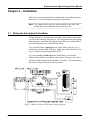
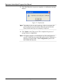
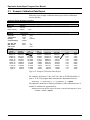
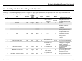
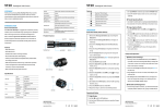
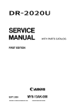
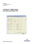
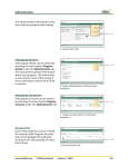
1
Form A6256 Part Number D301456X012 July 2009 Equimeter Auto-Adjust® Program (For FloBoss™ 107 Flow Managers) User Manual Remote Automation Solutions Equimeter Auto-Adjust Program User Manual Revision Tracking Sheet July 2009 This manual may be revised periodically to incorporate new or updated information. The revision date of each page appears at the bottom of the page opposite the page number. A change in revision date to any page also changes the date of the manual that appears on the front cover. Listed below is the revision date of each page (if applicable): Page All pages All pages Initial release Revision Jul-09 Feb-09 Mar-08 NOTICE “Remote Automation Solutions (“RAS”), division of Emerson Process Management shall not be liable for technical or editorial errors in this manual or omissions from this manual. RAS MAKES NO WARRANTIES, EXPRESSED OR IMPLIED, INCLUDING THE IMPLIED WARRANTIES OF MERCHANTABILITY AND FITNESS FOR A PARTICULAR PURPOSE WITH RESPECT TO THIS MANUAL AND, IN NO EVENT SHALL RAS BE LIABLE FOR ANY INCIDENTAL, PUNITIVE, SPECIAL OR CONSEQUENTIAL DAMAGES INCLUDING, BUT NOT LIMITED TO, LOSS OF PRODUCTION, LOSS OF PROFITS, LOSS OF REVENUE OR USE AND COSTS INCURRED INCLUDING WITHOUT LIMITATION FOR CAPITAL, FUEL AND POWER, AND CLAIMS OF THIRD PARTIES. Bristol, Inc., Bristol Canada, BBI SA de CV and Emerson Process Management Ltd, Remote Automation Solutions division (UK), are wholly owned subsidiaries of Emerson Electric Co. doing business as Remote Automation Solutions (“RAS”), a division of Emerson Process Management. FloBoss, ROCLINK, Bristol, Bristol Babcock, ControlWave, TeleFlow and Helicoid are trademarks of RAS. AMS, PlantWeb and the PlantWeb logo are marks of Emerson Electric Co. The Emerson logo is a trademark and service mark of the Emerson Electric Co. All other trademarks are property of their respective owners. The contents of this publication are presented for informational purposes only. While every effort has been made to ensure informational accuracy, they are not to be construed as warranties or guarantees, express or implied, regarding the products or services described herein or their use or applicability. RAS reserves the right to modify or improve the designs or specifications of such products at any time without notice. All sales are governed by RAS’ terms and conditions which are available upon request. RAS does not assume responsibility for the selection, use or maintenance of any product. Responsibility for proper selection, use and maintenance of any RAS product remains solely with the purchaser and end-user.” © 2008-2009 Remote Automation Solutions, division of Emerson Process Management. All rights reserved. ii Contents Rev. Jul-09 Equimeter Auto-Adjust Program User Manual Contents Page Chapter 1 – Introduction 1 1.1 SCOPE AND ORGANIZATION .....................................................................................................1 1.2 PRODUCT OVERVIEW...............................................................................................................1 1.3 PROGRAM REQUIREMENTS ......................................................................................................2 1.3.1 LICENSE KEYS .............................................................................................................2 Chapter 2 – Installation 3 2.1 WIRING THE AUTO-ADJUST TURBO METER ...............................................................................3 2.2 INSTALLING THE LICENSE KEY ..................................................................................................5 2.3 DOWNLOADING THE PROGRAM .................................................................................................7 Chapter 3 – Configuration 11 3.1 AUTO-ADJUST CONFIG SCREEN .............................................................................................13 3.1.1 AUTO-ADJUST CONFIG – SETUP TAB ..........................................................................14 3.1.2 AUTO-ADJUST CONFIG – ALARMS TAB ........................................................................18 3.3 SAVING THE CONFIGURATION .................................................................................................21 Chapter 4 – Reference Materials 23 4.1 EXAMPLE CALIBRATION DATA REPORT ...................................................................................24 4.2 POINT TYPE 31: AUTO-ADJUST PROGRAM CONFIGURATION ....................................................25 Rev. Jul-09 Contents iii Equimeter Auto-Adjust Program User Manual [This page is intentionally left blank.] iv Contents Rev. Jul-09 Equimeter Auto-Adjust Program User Manual Chapter 1 – Introduction This chapter describes the structure of this manual and presents an overview of the Equimeter Auto-Adjust® program for the FloBoss™ 107. 1.1 Scope and Organization This document serves as the user manual for the Equimeter Auto-Adjust program, which is intended for use in a FloBoss 107 (FB107). This manual describes how to download, install, and configure the Equimeter Auto-Adjust user program (referred to as the “Auto-Adjust program” or “the program” throughout the rest of this manual). You access and configure this program using ROCLINK™ 800 Configuration Software loaded on a personal computer (PC) running Windows® 2000 (with Service Pack 2), Windows XP, or Windows Vista. The sections in this manual provide information in a sequence appropriate for first-time users. Once you become familiar with the procedures and the software, the manual becomes a reference tool. This manual has the following major sections: Chapter 1 – Introduction Chapter 2 – Installation Chapter 3 – Configuration Chapter 4 – Reference This manual assumes that you are familiar with the FB107 and its configuration. For more information, refer to the FloBoss 107 Flow Manager Instruction Manual (Form A6206) or the ROCLINK 800 Configuration Software User Manual (for FloBoss 107) (Form A6217). 1.2 Product Overview The Auto-Adjust program enables a FB107 to calculate the pulse counters once each second for all configured and run-enabled Auto-Adjust points. Based on the frequency variations between the main and sensing rotors on the Turbo-Meter, the program calculates an adjusted volume rate. Using the Volume and % Error values from the Turbo-Meter calibration report (see the example calibration report included in Section 4.1, Example Calibration Data Report), you enter these values in the Auto-Adjust Calibration Curve pane on the Auto-Adjust Configuration screen (see Figure 12). The program uses these calibration-based correction values to calculate an “adjusted uncorrected volume factor,” or AUVF. If you enable the Auto-Adjust calibration curve, the program applies the AUVF to the adjusted volume rate. The adjusted volume rate is the parameter that should be used as the uncorrected volume input to the AGA 7 calculations, which results in a volume flow rate at base conditions. A maximum of two Auto-Adjust calculations are supported by the user program. The Rev. Jul-09 Introduction 1 Equimeter Auto-Adjust Program User Manual calculated adjusted flow rate and adjusted pulses are written to dedicated software pulse input points at locations A15 and A16. The adjusted volume calculation provides a measurement registration that adjusts flow values back to original factory calibration accuracy, thus compensating for meter changes or abnormal flow conditions. Note: When using the Auto-Adjust program on a FB107, you don’t need to use any other Equimeter equipment to interface with an AutoAdjust Turbo-Meter. For further information on the Auto-Adjust calculations, equations, and flowcharts, refer to the Auto-Adjust Turbo-Meter Algorithms manual available from Sensus Metering Systems (www.sensus.com). 1.3 Program Requirements The Auto-Adjust program is compatible with version 1.10 (or greater) of the FB107 firmware and with version 1.75 (or greater) of the ROCLINK 800 software. Program specifics include: File Name Target Unit/ Version User Defined Point (UDP) Flash Used (in bytes) DRAM Used (in bytes) ROCKLINK 800 Version Display Number autoadjust_5.bin FB107 1.10 31 13,134 16,384 1.75 32 Note: You must connect a PC to the FB107’s LOI port before starting the download. For information on viewing the memory allocation of user programs, refer to ROCLINK 800 Configuration Software User Manual (for FloBoss 107) (Form A6217). 1.3.1 License Keys Some applications require that you install a license in the CPU to run the application. This license software is specific to these applications and is the property of the individual vendor (shown in the Vendor Name field on the License Key Administrator screens). RAS (and other authorized vendors) distributes software licenses on security-enhanced universal serial bus (USB) drives. You must install the following license keys to use the Auto-Adjust Program. 2 AutoAdjust License Key. Introduction Rev. Jul-09 Equimeter Auto-Adjust Program User Manual Chapter 2 – Installation This section provides instructions for installing the Auto-Adjust program. Read Section 1.3 of this manual for program requirements. Note: The program and license key can be installed in any order. This manual shows the installation of the license key first. 2.1 Wiring the Auto-Adjust Turbo Meter Wiring an FB107 to an Equimeter Auto-Adjust Turbo-Meter requires that you use a Dual-Channel safety barrier. You can purchase the safety barrier from Equimeter. Install the safety barrier in the Safe Area with the FB107, not in the Hazardous Area with the Turbo-Meter. You can install either a blade tip sensor Turbo-Meter (refer to Figure 1 and Invensys drawing MM-1922-B) or a slot sensor Turbo-Meter (refer to Figure 2 and Invensys drawing MM-2126-B). If you are installing a blade tip sensor Turbo-Meter, use two DualChannel safety barriers and a power safety barrier. The power for each of the Dual-Channel safety barriers should be 24 Volts dc. You cannot power the barriers from the PI point of the I/O module. Figure 1. Blade Tip Sensor Turbo-Meter Wiring Diagram Rev. Jul-09 Installation 3 Equimeter Auto-Adjust Program User Manual If you are installing a slot sensor Turbo-Meter, the power for the DualChannel safety barrier should be from an external source. Figure 2. Slot Sensor Turbo-Meter Wiring Diagram Note: For either the blade tip or slot sensor Turbo-Meter, be sure to follow all instructions on the Invensys drawings and on any literature that accompanies the safety barrier and Turbo-Meter. 4 Installation Rev. Jul-09 Equimeter Auto-Adjust Program User Manual 2.2 Installing the License Key To install a USB key-based license on the FB107: 1. Insert the USB license key in a USB port on your PC. 2. Select Utilities > License Key Administrator > Transfer Between Device and Key from the ROCLINK 800 menu bar. The Transfer Licenses Between a Device and a Key screen displays. Figure 3. Transfer Licenses Between a Device and a Key Rev. Jul-09 Installation 5 Equimeter Auto-Adjust Program User Manual Note: This screen has three sections. The upper portion (Licenses on Device) shows any software licenses installed on the FB107. The middle portion (Licenses on Key) shows software licenses on the license key. The lower portion of the screen (License Key Event Log) provides a rolling log of the last eight events related to this license key. 3. Select the key-based license you want to transfer to the FB107 (AutoAdjust, as shown in Figure 3). 4. Click Move to Device. ROCLINK moves one instance of the license from the key to the FB107 and updates the screen. Figure 4. License Installed Note: An FB107 can hold up to six different licenses, although you can install only one instance of each license on the FB107. When you click Move to Device, ROCLINK 800 moves only one instance of the license onto the FB107 and automatically decreases the license quantity on the USB key by one. 5. Verify the license name displays in the Licenses on Device section of the screen. Proceed to Section 2.3 to download the user program. 6 Installation Rev. Jul-09 Equimeter Auto-Adjust Program User Manual 2.3 Downloading the Program This section provides instructions for installing the program into the Flash memory on the FB107. To download the program using ROCLINK 800 software: 1. Connect the FB107 to your computer using the LOI port. 2. Start and logon to ROCLINK 800. 3. Select Utilities > User Program Administrator from the ROCLINK menu bar. The User Program Administrator screen displays (see Figure 5): Figure 5. User Program Administrator 4. Click Browse in the Download User Program File frame. The Select User Program File screen displays (see Figure 6). 5. Select the path and user program file to download from the CD-ROM. (Program files are typically located in the Program Files folder on the CD-ROM). As Figure 6 shows, the screen lists all valid user program files with the .BIN extension: Rev. Jul-09 Installation 7 Equimeter Auto-Adjust Program User Manual Figure 6. Select User Program File 6. Click Open to select the program file. The User Program Administrator screen displays. As shown in Figure 7, note that the Download User Program File frame identifies the selected program and that the Download & Start button is active: Figure 7. User Program Administrator 8 Installation Rev. Jul-09 Equimeter Auto-Adjust Program User Manual 7. Click Download & Start to begin loading the selected programs. The following message displays: Figure 8. Confirm Download 8. Click Yes to begin the download. When the download completes the following message displays: Figure 9. ROCLINK 800 Download Confirmation 9. Click OK. The User Program Administrator screen displays (see Figure 10). Note that: The User Programs Installed in Device frame identifies the installed program(s). The Status field indicates that the program is running. Figure 10. User Program Administrator Rev. Jul-09 Installation 9 Equimeter Auto-Adjust Program User Manual Note: If you install the program before you install the license key, the Status field reads “License Key Not Found.” 10. Click Close. The ROCLINK 800 screen displays and the download is complete. 10 Installation Rev. Jul-09 Equimeter Auto-Adjust Program User Manual Chapter 3 – Configuration After you have loaded the Auto-Adjust program on the FB107, you configure the program using two tabs (Setup and Alarms) on one programspecific screen (Auto-Adjust Config): Use the Setup tab to set a number of program configuration values (including inputs, factor values, and other parameters) and enable the calculations. Use the Alarms tab to configure program-specific alarms. To configure the program (after logging onto ROCLINK 800 and successfully installing the program and license key), proceed through the program screens as shown in this section. Note: Once you have completed the configuration process for the Auto- Adjust program, review the ROCLINK 800 turbine meter setup screen to determine if any additional configuration is required. The adjusted flow rate is used as the uncorrected flow rate for a turbine meter (AGA 7). The Turbine Meter point type includes all parameters that need to be archived for collection by the EFM reports. The Auto-Adjust program writes to dedicated software pulse input points. The program sets the calculated adjusted flow (in MCF/day or KM3/day) and adjusted raw pulses/input at locations A15 (meter run 1) and A16 (meter run 2). These software pulse inputs should be used as the input to turbine meter AGA7 calculations. You can access all the program-specific screens from the main ROCLINK 800 screen: Rev. Jul-09 Configuration 11 Equimeter Auto-Adjust Program User Manual Figure 11. ROCLINK 800 Note: The number of sub-entries associated with each screen (#1, AAT #1 in the example above) indicates the number of calculations licensed to this program. 12 Configuration Rev. Jul-09 Equimeter Auto-Adjust Program User Manual 3.1 Auto-Adjust Config Screen Use this screen to set configuration values and configure active programspecific alarms for the Auto-Adjust program. To access this screen: 1. From the Directory Tree, select User Program > AutoAdjust User Prgm. 2. Double-click Display #32, Auto-Adjust Config. 3. Double-click #1, AAT #1. The Auto-Adjust Config screen displays: Figure 12. Auto-Adjust Config screen Note: The Auto-Adjust Config screen has a tab format. Sections 3.1.1 and 3.1.2 discuss the requirements for each tab on the Auto-Adjust Config screen. Rev. Jul-09 Configuration 13 Equimeter Auto-Adjust Program User Manual 3.1.1 Auto-Adjust Config – Setup Tab Use this tab (which displays when you to access the Auto-Adjust Config screen) to set configuration values for the Auto-Adjust program. Figure 13. Auto-Adjust Config, Setup tab 1. Review—and change as necessary—the values in the following fields. Field Description Point Number Indicates the Auto-Adjust point to be configured. Click d to display all available points. Note: A maximum of two Auto-Adjust meter runs are supported. 14 Turbine Tag Displays the name associated with this turbine. This tag can be up to 10 characters in length. Units Indicates the measurement units the program uses for calculations. Valid values are US or Metric. The default is US. Auto-Adjust Algorithm Indicates the state of the Auto-Adjust Turbo-Meter defined in this logical. Valid values are Enabled (active) or Disabled (inactive). The default is Disabled. Configuration Rev. Jul-09 Equimeter Auto-Adjust Program User Manual Field Description Reset Algorithm Forces, when the Auto-Adjust algorithm is enabled, the algorithm to reset (as with a warm start). The reset clears all accumulators and timers associated with the self-checking algorithm. When the reset is complete, the program returns to Normal setting. Valid values are Normal (do not force the reset) or Reset (force the reset). The default is Normal. Calibration Mode Sets the rotor calibration mode. Valid values are Enabled (which uses a self-checking cycle of 2,500 rotations) or Disabled (which uses the standard cycle of 25,000 rotations). The default is Disabled. Selecting Enabled shortens the amount of cycle used during calibration of the FB107. Adjusted Volume Rate Indicates, in MCF/day or KM3/day, the flow rate determined by the auto-adjust algorithm and the AUVF (if enabled) at flowing conditions. The system updates this value once per second. This is a parameter that should be used as input to the AGA 7 calculations. Mechanical Volume Rate Indicates, in MCF/day or KM3/day, the unadjusted flow rate based on the main rotor pulses and the mechanical K-factor. The system updates this value once per second. This parameter does not have compensation from the auto-adjust algorithm. Note: The AGA 7 firmware expects a flow rate (in either MCF/day or KM3/day) when reading an uncorrected value other than from a pulse input point. Rev. Jul-09 Main Rotor Pulse Input Indicates the particular pulse input for the turbine’s main rotor. Click … to display a TLP screen to define the input. The program ignores the selected parameter for a pulse input. Sensing Rotor Pulse Input Indicates the particular pulse input for the turbine’s sensing rotor. Click … to display a TLP screen to define the input. The program ignores the selected parameter for a pulse input. Main Rotor K-Factor Indicates, in pulses/ft3 or pulses/m3, a scaling Kfactor the program uses to convert the main rotor pulses to either pulses/ft3 or pulses/m3. Sensing Rotor K-Factor Indicates, in pulses/ft3 or pulses/m3, a scaling Kfactor the program uses to convert the sensing rotor pulses to either pulses/ft3 or pulses/m3. Mechanical K-Factor Indicates, in pulses/ft3 or pulses/m3, a K-factor as provided from the Equimeter calibration sheet. The program uses this value to calculate a Mechanical Volume rate or un-adjusted volume, which matches the Turbo-Meter mechanical totalizer volume. Configuration 15 Equimeter Auto-Adjust Program User Manual Field Description Pipe Diameter Indicates, in inches or mm, the pipe’s approximate internal diameter. Note: The program uses this value to complete the Blade Tip Sensor Factor field on the Auto-Adjust Alarms screen. Average Rel. Adjustment Indicates, as a percentage, the average relative adjustment for the auto-adjust algorithm determined at factory calibration. Maximum Frequency Indicates, in Hz, the maximum frequency value the program uses when calculating the meter load, expressed as Current Frequency or Maximum Frequency. Auto-Adjust Calibration Curve Activates the Auto-Adjust Calibration Curve calculation. Valid values are Enabled (calculate the Adjusted Uncorrected Volume Factor [AUVF]) or Disabled (do not allow the AUVF calculation, which is equal to an AUVF of 1.00). Note: If you enable the calibration curve, the program applies the AUVF factor to the result of the auto-adjust algorithm to calculate the adjusted volume rate at flowing conditions. If you disable the calibration curve, the adjusted volume rate reflects the result of the auto-adjust algorithm with no correction for the calibration curve. AAT Volume Sets the AAT volume for up to 10 pairs of AAT Volume–%Err numbers on the calibration curve. The program uses this value (along with the value in the % Err field) to linearly interpolate the Adjusted Volume Rate. Note: When you enter values for each AAT Volume–% Err pair, ensure that the AAT Volume component for each pair is greater than the AAT volume component of the immediately previous pair. Otherwise the program ignores the first lower and all subsequent pairs, regardless of the value of the AAT Volume component. For example, in the pair sequence (where the first value represents the AAT Volume and the second value is the % Error): Pair 1: 100, –0.5 Pair 2: 300, 0.3 Pair 3: 800, 1.2 Pair 4: 500, 1.1 Pair 5: 1000, 0.7 The AAT Volume in pair 4 is less than the AAT Volume in pair 3. The program then uses the % Err value of 1.2 for any volume above 800, regardless of what you’ve defined in pairs 4 or 5. 16 Configuration Rev. Jul-09 Equimeter Auto-Adjust Program User Manual Field Description % Error Sets the % Error value for up to 10 pairs of AAT Volume–% Err numbers on the calibration curve. The program uses this value (along with the value in the AAT Volume field) to linearly interpolate the Adjusted Volume Rate. Adjusted Uncorr Volume Factor (AUVF) This read-only field displays the Adjusted Uncorrected Volume Factor (AUVF), which the program calculates as equal to [1 / (% Err/100) + 1]. 2. Click Apply to save your changes. 3. Click Close to return to the ROCLINK 800 screen. Proceed to Section 3.1.2 to configure alarming options. Rev. Jul-09 Configuration 17 Equimeter Auto-Adjust Program User Manual 3.1.2 Auto-Adjust Config – Alarms Tab Use this tab to configure program-specific alarms. To access this screen: 1. Select the Alarms tab on the Auto-Adjust Config screen. The Alarms tab displays: Figure 14. Auto-Adjust Config, Alarms tab 2. Review—and change as necessary—the values in the following fields: 18 Field Description Point Number Indicates the Auto-Adjust point to be configured. Click d to display all available points. Turbine Tag Displays the name associated with this turbine. This tag can be up to 10 characters in length. Test Timer This read-only field shows the number of seconds elapsed since the program last started the Auto-Adjust self-checking calculation. The program resets this value either after 512 seconds or when the main rotor reaches 25,000 pulses, whichever occurs first. Test Pulses This read-only field shows the rotor pulses accumulated during the current self-checking calculation cycle. A self-checking calculation cycle takes either 25,000 rotor rotations or 512 seconds, whichever occurs first. Configuration Rev. Jul-09 Equimeter Auto-Adjust Program User Manual Field Description Current Frequency (Hz) This read-only field shows, in Hz, the current frequency for both the main and sensing rotors. The program updates this value once each second. Current Flow Rate (ft3/sec) This read-only field shows, in ft3/second or m3/second, the raw volumetric rate for both the main and sensing rotors. The program calculates this value as pulse/second divided by K-factor for the rotor. Test Accum Volume (ft3) This read-only field shows, in ft3 or m3, the raw volume values for both the main and sensing rotors during the current self-adjusting calculation cycle. Baseline Delta A Indicates, as a percentage, the baseline delta adjustment (Delta A) value derived either from the factory calibration curve or the initial field testing. Note: The program’s run-time warning and alarm limits depend on this value. For example, the program calculates the low warning limit as the Baseline Delta Adjustment value minus the Normal Band value and the high alarm limit as the Baseline Delta Adjustment value plus the Abnormal Band value. Calculated Delta A This read-only field shows, as a percentage, the system-calculated delta adjustment (Delta A) value. This value is the amount of change that has occurred in the meter or flow condition compared to its original calibration value. The program refreshes this value at least every 512 seconds or 25,000 rotations of the main rotor. Normal Band Indicates, as a percentage, the normal limits above and below the Baseline Delta A value. The default value is 0.2. If the percentage exceeds this value, the program triggers a warning. Abnormal Band Indicates, as a percentage, the abnormal limits above and below the Baseline Delta A value. The default value is 0.3. If the percentage exceeds this value, the program triggers an alarm. Calculated Load This read-only field shows, as a percentage, the instantaneous turbine load, calculated as the current main rotor frequency divided by the maximum frequency. The program updates this value once every second. Blade TipSensor Factor This read-only field shows a predefined factor based on the value entered in the Pipe Diameter field on the Auto-Adjust Configuration screen. Note: The program considers any pipe diameter between 7 and 10 inches as 8 inches, to correspond to the Equimeter meter choices of 4, 6, 8, and 12 inches. Rev. Jul-09 Configuration 19 Equimeter Auto-Adjust Program User Manual Field Description Status Message This read-only field shows the status of the Auto-Adjust turbine. The values displayed in this field correspond to the values defined in the various Alarm panes (on the right-hand side of the Auto-Adjust Alarms screen). System Alarm This read-only field indicates the current system status. Possible system alarms include: Normal Flow, No Flow or Loss of Both Rotor, Leakage or Resonant No-Net Flow, No Main Rotor Pulses Or Leakage Or Resonant No-Net Flow, and No Sensing Rotor Pulses. Delta A Alarm This read-only field indicates whether the program-calculated deviation from the average relative adjustment is within normal limits. Possible Delta A alarms include: Normal, Low Warning, High Warning, Low Alarm, and High Alarm. Initial Cycle Status This read-only field indicates whether the initial cycle has started or is complete. Flow Alarm Indicates the status of the ratio between the sensing rotor’s volume and the main rotor’s volume. Valid values are Normal Flow (the ratio is steady) or Non-Steady Flow (the ratios are below acceptable limits). Manual Input Alarm This read-only field indicates whether one or both Pulse Inputs to the Auto-Adjust algorithm are undefined on the I/O Definition pane on the Auto-Adjust Configuration screen. Valid values are Inputs Defined (you have defined TLP values in the I/O Definition pane for both the main and sensing rotors) or Manual Inputs (you have not defined TLP values in the I/O Definition pane for both the main and sensing rotors). 3. Click Apply to save your changes. 4. Click Close to return to the ROCLINK 800 screen. Proceed to Section 3.2 to save your configuration. 20 Configuration Rev. Jul-09 Equimeter Auto-Adjust Program User Manual 3.3 Saving the Configuration Whenever you modify or change the configuration, it is a good practice to save the final configuration to memory. To save the configuration: 1. Select ROC > Flags. The Flags screen displays: Figure 15. Flags 2. Click Save Configuration. A verification message displays: Figure 16. Save Verification Rev. Jul-09 Configuration 21 Equimeter Auto-Adjust Program User Manual 3. Click Yes. When the save process completes, a confirmation message displays: Figure 17. Confirmation Note: Depending on the size and complexity of the user program, this process may take several minutes. When the process ends, the Status field on the Flags screen displays Completed. 4. Click Update on the Flags screen. This completes the process of saving your new configuration. Note: For archive purposes, you should also save this configuration to your PC’s hard drive or a removable media (such as a diskette or a flash drive) using the File > Save Configuration option on the ROCLINK 800 menu bar. 22 Configuration Rev. Jul-09 Equimeter Auto-Adjust Program User Manual Chapter 4 – Reference Materials This section provides an example calibration data report and tables of information on the user-defined point types used by the Auto-Adjust program. Rev. Jul-09 Example Calibration Data Report Point Type 31 (Auto-Adjust Program Configuration) Reference 23 Equimeter Auto-Adjust Program User Manual 4.1 Example Calibration Data Report Following is an example calibration data report, which a calibration service provides. Applicant: Remote Automation Solutions Meter Type: Meter S/N Model Meter Capacity 29835647 ATT-230 230000 act/h Auto Adjust Test Data (As Left) Medium: Natural Gas Pressure: 896.33 Temperature: 81.83 Density: 2.86 Compressibility: 0.90062 Ave. Rel. Adj. M.R. Factor S.R. Factor Gear Set Prover Rate (Acf/hr) 226318.16 183957.54 139660.54 114882.18 80701.70 57863.88 34801.46 23147.60 11761.08 6544.63 2424.77 9.9713 6.9211 AAT Vol (Acf/hr) 225280.68 183279.74 139173.91 114688.51 80702.71 57933.97 34885.32 23221.87 11825.83 6596.35 2452.19 (PSI) (°F) (Lbs/ft3) % p/ft3 p/ft3 M.R. Freq Hz 476.7708 387.6479 294.2501 242.3503 170.5003 122.3862 73.7133 49.0866 25.0156 13.9485 5.1582 S.R. Freq Hz 54.4584 44.0127 33.2823 27.2631 19.1417 13.7280 8.2884 5.5402 2.8439 1.5801 0.5535 M.R.Vol S.R.Vol 247991.64 201634.50 153053.76 126058.14 88685.47 63659.00 38341.87 25532.30 13011.81 7255.29 2683.02 22710.96 18354.76 13879.85 11369.64 7982.75 5725.03 3456.56 2310.43 1185.98 658.94 230.84 Error (%) –0.46 –0.37 –0.35 –0.17 0.00 0.12 0.24 0.32 0.55 0.79 1.13 Delta A (%) 0.110 0.043 0.002 –0.058 –0.080 –0.089 –0.063 –0.022 0.057 0.018 –0.558 Figure 18. Example Calibration Data Report For example, for data set 1, the AAT Vol value is 225280.68 and the % error is –0.46. The program then calculates the adjustment factor as: AUVF Factor = 1 / ((%err/100) + 1) = 1 / ((–0.46/100) + 1) = 1.004621 The adjusted volume rate at flowing conditions, if the calibration curve is enabled, would then be approximately: Adjusted volume rate (used as input to the AGA) = value from AAT algorithm * factor = 225850 * 1.004621 = 226318 24 Reference Rev. Jul-09 Equimeter Auto-Adjust Program User Manual 4.2 Point Type 31: Auto-Adjust Program Configuration Point type 31 contains the parameters used to configure the Auto-Adjust turbine meter and the results of the Auto-Adjust calculation. The program maintains up to 2 logical points and saves point type 31 information to internal configuration memory. Parm # Name Access Program or User Update Data Type Length Range Default 0 Point Tag ID R/W User AC 10 0x20 → 0x7E for each ASCII character 1 Reserved R/W Program UINT8 1 NA “AAT #X” where X is the meter number 0 2 Calculation Option R/W User UINT8 1 0→1 0 3 Reset R/W User UINT8 1 0→1 0 4 Main Rotor Pulse Input R/W User TLP 3 TLP 0,0,0 and TLP 105,5→148, Any 0, 0, 0 5 Main Rotor K-Factor R/W User Float 4 Any positive, nonzero, valid IEEE 754 float 1.0 6 Main Rotor Frequency R/O Program Float 4 0 → positive valid IEEE 754 float 0.0 7 Main Rotor Volume Rate R/O Program Float 4 0 → positive valid IEEE 754 float 0.0 8 Main Rotor Test Accum Volume R/O Program Float 4 0 → positive valid IEEE 754 float 0.0 Rev. Jul-09 Reference Description of functionality and meaning of values Identification name for the Auto-Adjust meter. Values must be printable ASCII characters. Not Used Indicates whether the AutoAdjust flow calculation is enabled for this meter run. 0 = Disabled 1 = Enabled. Selection performs a reset on the self-checking routine of the Auto-Adjust turbine meter. Selecting a reset clears all accumulations and timers associated with the selfchecking routine. 0 = Normal 1 = Reset. Pulse input feed from main rotor on the auto-adjust turbine meter. Scale factor to convert main rotor pulses to volume in 3 3 pulses/ft or pulses/m . Current frequency of the main rotor pulse stream in pulses/second. Current un-adjusted volumetric flow rate of the main rotor in 3 3 ft /second or m /second. Accumulated volume from the main rotor for the current self3 3 checking routine in ft or m . 25 Equimeter Auto-Adjust Program User Manual 26 Parm # Name Access Program or User Update Data Type Length Range Default 9 Test Accum Pulses R/O Program UINT32 4 0 → 4,294,967,295 0.0 10 Sensing Rotor Pulse Input R/W User TLP 3 TLP 0,0,0 and TLP 105,5→148, Any 0, 0, 0 11 Sensing Rotor K-Factor R/W User Float 4 Any positive, nonzero, valid IEEE 754 float 1.0 12 Sensing Rotor Frequency R/O Program Float 4 0 → positive valid IEEE 754 float 0.0 13 Sensing Rotor Volume Rate R/O Program Float 4 0 → positive valid IEEE 754 float 0.0 14 Sensing Rotor Test Accum Volume R/O Program Float 4 0 → positive valid IEEE 754 float 0.0 15 Reserved R/O Program U32 4 NA 0 16 Adjusted Flow Rate R/O Program Float 4 0 → positive valid IEEE 754 float 0.0 17 Mechanical Flow Rate R/O Program Float 4 0 → positive valid IEEE 754 float 0.0 18 Self-Test Timer R/O Program U16 2 0 → 65535 0 19 Pipe Diameter R/W User Float 4 Any positive, nonzero, valid IEEE 754 float 6.0 Reference Description of functionality and meaning of values Accumulated pulses from the main rotor for the current selfchecking routine. Pulse input feed from the sensing rotor on the AutoAdjust turbine meter. Scale factor to convert the sensing rotor pulses to volume 3 3 in pulses/ft or pulses/m . Current frequency of the sensing rotor pulse stream in pulses/second. Current un-adjusted volumetric flow rate of the sensing rotor in 3 3 ft /second or m /second. Accumulated volume from the sensing rotor for the current self-checking routine in ft3 or 3 m. Not Used Adjusted volumetric flow rate at flowing conditions in MCF/Day 3 or E3m /Day. This is the flow rate calculated using the AutoAdjust algorithm and corrected for AUVF (if enabled). Un-adjusted or mechanical volumetric flow rate in 3 MCF/Day or E3m /Day. This value reflects the main rotor pulses converted to volume using the mechanical K-Factor (parameter #25). Amount of time elapsed in the current self-checking cycle in seconds. Internal diameter of the meter piping in inches or mm. A blade tip sensor factor (parameter #19) is determined based on this diameter. Rev. Jul-09 Equimeter Auto-Adjust Program User Manual Parm # Name Access Program or User Update Data Type Length Range Default 20 Blade Factor R/O Program Float 4 2.0, 2.5, 3.33, or 4.0 3.33 21 Maximum Frequency R/W User Float 4 Any positive, nonzero, valid IEEE 754 float 10000.0 22 Calculated Load R/O Program Float 4 0.0 → 100.0 0.0 23 Average Relative Adjustment R/W User Float 4 0.0 → 100.0 0.0 24 Baseline Delta A R/W User Float 4 –100.0 → 100.0 0.00 25 Calculated Delta A R/O Program Float 4 –100.0 → 100.0 0.00 26 Mechanical K-Factor R/W User Float 4 Any positive, nonzero, valid IEEE 754 float 1.00 27 Normal Band R/W User Float 4 0.0 → 100.0 0.2 28 Abnormal Band R/W User Float 4 0.0 → 100.0 0.3 Rev. Jul-09 Reference Description of functionality and meaning of values Factor used to determine a minimum main rotor frequency to perform self-checking function. Maximum rated frequency of the main rotor in Hz. This value is used to calculate a percent load on the meter (parameter #21). Percent load on the meter based on the user entered maximum frequency (parameter #20). Average relative adjustment (%) determined at factory calibration. Average delta A values determined over a period of time during normal flow rates above 10% of meter capacity. Percent deviation from Average Relative Adjustment (parameter #22). Scale factor to convert the main rotor pulses to volume without adjustment from the sensing rotor in pulses/ft3 or pulses/m3. Allowable limit above and below the baseline delta A (parameter #23) above which a warning indication is displayed. Allowable limit above and below the baseline delta A (parameter #23) above which an alarm indication is displayed. 27 Equimeter Auto-Adjust Program User Manual Parm # 28 Name Access Program or User Update Data Type Length Range Default 29 System Alarm R/O Program UINT8 1 0→4 0 30 Delta A Alarm R/O Program UINT8 1 0→4 0 31 Non-Steady Flow Alarm R/O Program UINT8 1 0→1 0 32 Manual Input Alarm R/O Program UINT8 1 0→1 0 33 Initial Cycle Status R/O Program UINT8 1 0→1 0 Reference Description of functionality and meaning of values System alarm indicating the condition of the Auto-Adjust turbine meter. 0 = Normal Flow 1 = No Flow or Loss of Both Rotor Pulses 2 = Leakage Flow or Resonant No-Net Flow 3 = No Main Rotor Pulses or Leakage Flow or Resonant NoNet Flow 4 = No Sensing Rotor Pulses. Status indicating whether calculated deviation from Average Relative Adjustment is within normal limits. 0 = Normal, 1 = Low Warning 2 = High Warning 3 = Low Alarm 4 = High Alarm. Status indicating that the ratio of the sensing rotor volume to main rotor volume is below acceptable limits. 0 = Normal Flow 1 = Non-Steady Flow. Status indicating one or both of the inputs to the Auto-Adjust algorithm are undefined. Status indicating whether the initial self-checking cycle has been completed or not. 0 = Initial cycle complete 1 = Initial cycle in progress. Rev. Jul-09 Equimeter Auto-Adjust Program User Manual Parm # 34 Name Auto-Adjust Status Message Access R/O Program or User Update Program Data Type Length Range 20 “Non-Steady Flow Alrm” or “NonSteady Flow Warn” or “NoFlow/Loss Both Pls” or “Leak/Res No-Net Flow” or “NoMR Pls/Leakage/Res” or “No Sensing Pulses” or “Initial Test Cycle” or “Abnormal Alarm Low” or “Abnormal Warning Low” or “Abnormal Alarm High” or “Abnormal Warning Hi” or “Self Check OK” AC Default Status message indicating current alarm conditions. “Initial Test Cycle” 35 Auto-Adjust Calibration Mode R/W User UINT8 1 0→1 0 36 Adjusted Uncorrected Volume Factor Option R/W User UINT8 1 0→1 0 37 Adjusted Uncorrected Volume Factor R/O Program Float 4 0.0 →10.0 0.0 38 Auto Adjust Volume 1 % Error R/W User Float 4 39 Auto Adjust Volume 1 R/W User Float 4 40 Auto Adjust Volume 2 % Error R/W User Float 4 41 Auto Adjust Volume 2 R/W User Float 4 42 Auto Adjust Volume 3 % Error R/W User Float 4 Rev. Jul-09 Reference Any valid IEEE 754 float Any positive nonzero valid IEEE 754 float Any valid IEEE 754 float Any positive nonzero valid IEEE 754 float Any valid IEEE 754 float Description of functionality and meaning of values 0.0 0.0 0.0 0.0 0.0 Selects calibration mode 0 = Normal Calibration Mode (max of 25,000 pulses) 1 = Test Calibration Mode (max of 2500 pulses) Activates the calculation of the Adjusted Uncorrected Volume Factor (AUVF) 0 = Do not calculate 1 = Calculate and apply AUVF The adjusted uncorrected volume factor calculated from the calibration data report. Percentage error for calibration volume 1. Calibrated volume 1 in MCF/day or E3m3/day. Percentage error for calibration volume 2. Calibrated volume 2 in 3 MCF/day or E3m /day. Percentage error for calibration volume 3. 29 Equimeter Auto-Adjust Program User Manual 30 Parm # Name Access Program or User Update Data Type Length 43 Auto Adjust Volume 3 R/W User Float 4 44 Auto Adjust Volume 4 % Error R/W User Float 4 45 Auto Adjust Volume 4 R/W User Float 4 46 Auto Adjust Volume 5 % Error R/W User Float 4 47 Auto Adjust Volume 5 R/W User Float 4 48 Auto Adjust Volume 6 % Error R/W User Float 4 49 Auto Adjust Volume 6 R/W User Float 4 50 Auto Adjust Volume 7 % Error R/W User Float 4 51 Auto Adjust Volume 7 R/W User Float 4 52 Auto Adjust Volume 8 % Error R/W User Float 4 53 Auto Adjust Volume 8 R/W User Float 4 54 Auto Adjust Volume 9 % Error R/W User Float 4 55 Auto Adjust Volume 9 R/W User Float 4 56 Auto Adjust Volume 10 % Error R/W User Float 4 57 Auto Adjust Volume 10 R/W User Float 4 Reference Range Any positive nonzero valid IEEE 754 float Any valid IEEE 754 float Any positive nonzero valid IEEE 754 float Any valid IEEE 754 float Any positive nonzero valid IEEE 754 float Any valid IEEE 754 float Any positive nonzero valid IEEE 754 float Any valid IEEE 754 float Any positive nonzero valid IEEE 754 float Any valid IEEE 754 float Any positive nonzero valid IEEE 754 float Any valid IEEE 754 float Any positive nonzero valid IEEE 754 float Any valid IEEE 754 float Any positive nonzero valid IEEE 754 float Default 0.0 0.0 0.0 0.0 0.0 0.0 0.0 0.0 0.0 0.0 0.0 0.0 0.0 0.0 0.0 Description of functionality and meaning of values Calibrated volume 3 in MCF/day or E3m3/day. Percentage error for calibration volume 4. Calibrated volume 4 in 3 MCF/day or E3m /day. Percentage error for calibration volume 5. Calibrated volume 5 in 3 MCF/day or E3m /day. Percentage error for calibration volume 6. Calibrated volume 6 in MCF/day or E3m3/day. Percentage error for calibration volume 7. Calibrated volume 7 in MCF/day or E3m3/day. Percentage error for calibration volume 8. Calibrated volume 8 in MCF/day or E3m3/day. Percentage error for calibration volume 9. Calibrated volume 9 in MCF/day or E3m3/day. Percentage error for calibration volume 10. Calibrated volume 10 in MCF/day or E3m3/day. Rev. Jul-09 Equimeter Auto-Adjust Program User Manual [This page is intentionally left blank.] Rev. Jul-09 Reference 31 Equimeter Auto-Adjust Program User Manual If you have comments or questions regarding this manual, please direct them to your local sales representative or contact: Emerson Process Management Remote Automation Solutions Marshalltown, Iowa 50158 USA Houston, TX 77065 USA Pickering, North Yorkshire UK Y018 7JA Website: www.EmersonProcess.com/Remote