1
TiNAMiCS CO.,LTD.
Altistart 48 soft start soft stop units
Catalogue
February
Taming
energy
VVDED202024EN
2002
Schneider Electric Industries SA
Siège social
89, bd Franklin Roosevelt
F - 92500 Rueil-Malmaison
Cedex
ART. 011237
http://www.schneider-electric.com
February 2002
Get more with the world’s Power & Control specialist
www.thianovation.com
3UHVHQWDWLRQ
TiNAMiCS CO.,LTD.
6RIWVWDUWHUV
Altistart 48 soft start - soft stop units
2
www.thianovation.com
Schneider Electric
&KDUDFWHULVWLFVFRQWLQXHG
TiNAMiCS CO.,LTD.
6RIWVWDUWHUV
Altistart 48 soft start - soft stop units
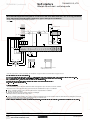
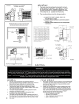
7RUTXHFKDUDFWHULVWLFV
Curves indicating changes in the torque depending on the starting current of a threephase asynchronous motor.
Curves 1: direct line starting
Curves 2: starting in current limiting mode
Torque curve Ts1 indicates the total torque range available depending on the limiting
current Is1.
Limiting the starting current Is to a preset value Is1 will reduce the starting torque Ts1
to a value which is almost equal to the square of currents Is1/Is.
Example:
For motor characteristics: Ts = 3 Tn for Is = 6 In,
limit the current to Is1 = 3 In (0.5 Is)
resulting in a starting torque Ts1 = Ts x (0.5)² = 3 Tn x 0.25 = 0.75 Tn
6WDUWLQJFXUUHQW
Direct line starting current
Starting current limited to Is1
I/In
6
5
1
4
2
Id1
3
2
1
0
0
0,25
0,5
0,75
1
N/Ns
6WDUWLQJWRUTXH
Direct line starting torque
Starting torque with current limited
C/Cn
6
to Is1
5
4
1
3
2
2
Cr
Cd1
1
0
0
Presentation:
pages 2 and 3
6
References:
pages 12 to 15
www.thianovation.com
Dimensions:
pages 20 to 23
0,25
0,5
0,75
1
N/Ns
Schemes:
pages 24 to 29
Schneider Electric
&KDUDFWHULVWLFVFRQWLQXHG
6RIWVWDUWHUV
TiNAMiCS CO.,LTD.
Altistart 48 soft start - soft stop units
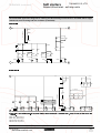
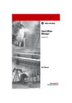
&RQYHQWLRQDOVWDUWLQJXVLQJFXUUHQWOLPLWDWLRQRUYROWDJHUDPS
With current limitation Is1, the accelerating torque applied to the motor is equal to the
motor torque Ts1 minus the resistive torque Tr.
The accelerating torque increases in the starting range as the speed changes and is
at its highest at the end of acceleration (curve 2).
This characteristic means that the load is taken up very abruptly, which is not
recommended for pump type applications.
Example of speed curve for starting with current
limitation
Current applied to the motor (I/In)
Motor speed N/Ns
I/In
4
N/Ns
1
1
3
2
0,5
2
1
0
t
6WDUWLQJZLWKWKH$OWLVWDUW
Torque control on the Altistart 48 applies the torque to the motor during the entire
starting phase if the current required (curve 1) does not exceed the limiting current.
The accelerating torque can be virtually constant over the entire speed range
(curve 2).
It is possible to set the Altistart in order to obtain a high torque on starting for a rapid
motor speed rise whilst limiting its temperature rise, and a lower accelerating torque
at the end of starting for gradual loading.
This control function is ideal for centrifugal pumps or for machines with high resistive
torque on starting.
Example of speed curve for starting with torque control
Current applied to the motor (I/In)
Motor speed N/Ns
I/In
4
N/Ns
1
3
1
2
0,5
2
1
0
t
6WRSSLQJZLWKWKH$OWLVWDUW
# Freewheel stop: the motor comes to a freewheel stop.
# Decelerated stop: this type of stop is ideal for pumps and can be used to effectively
reduce pressure surges. Torque control on the Altistart 48 reduces the effect of
hydraulic transients even if the load increases. This type of control makes adjustment
easy.
# Braked stop: this type of stop is suitable for high inertia applications as it reduces
the stopping time of the machine.
Presentation:
pages 2 and 3
Schneider Electric
References:
pages 12 to 15
www.thianovation.com
Dimensions:
pages 20 to 23
Schemes:
pages 24 to 29
7
6HOHFWLRQFULWHULDFRQWLQXHG
6RIWVWDUWHUV
TiNAMiCS CO.,LTD.
Altistart 48 soft start - soft stop units
6SHFLDOXVHV
Other criteria can influence the selection of the Altistart 48:
6WDUWHUZLUHGWRWKHPRWRUGHOWDWHUPLQDO
(see the recommended application diagram on page 26)
In addition to the most frequently encountered wiring layouts, where the starter is
installed in the line supply of the motor and the motor is connected in star or delta
configuration, the Altistart 48 ATS48•••Q can be wired to the motor delta terminal in
series with each winding (see the application diagram below). The starter current is
lower than the line current absorbed by the motor by a ratio of
. This type of
installation enables a starter with a lower rating to be used.
Example: For a 400 V/110 kW motor with a line current of 195 A (nominal current for
the delta connection), the current in each winding is equal to 195/ , i.e. 114 A.
Select the starter rating with a maximum permanent nominal current just above this
current, i.e. 140A (ATS48C14Q for a standard application).
To avoid making this calculation, simply use the table on page 13.
This type of installation only permits freewheel stopping and is not compatible with
the cascade and preheating functions.
$764
PRWRU
Starter wired in series with the motor
windings
: The nominal current and limiting current settings as well as the current
displayed during operation are on-line values (so do not have to be calculated by the
user).
1RWH
&DXWLRQ: For this type of installation, observe the wiring scheme and the associated
recommendations on page 26.
6WDUWHUE\SDVVHGE\ DFRQWDFWRU
(see the recommended application diagram on page 25)
The starter can be bypassed by a contactor at the end of starting (to limit the heat
dissipated by the starter). The bypass contactor is controlled by the starter and the
current measurements and protective mechanisms remain active when the starter is
bypassed.
The starter is selected on the basis of the 3 main criteria and one of the following
criteria:
If the starter is bypassed at the end of starting, the motor is always started from
cold state and the starter can be oversized by one rating.
Example: Select an ATS 48D17Q for an 11 kW motor in a standard 400 V application.
#
#
If the starter must be able to operate without the bypass contactor at the end of
starting, it does not have to be derated.
Example: Select an ATS 48D17Q for a 7.5 kW motor in a standard 400 V application.
10
www.thianovation.com
Schneider Electric
TiNAMiCS CO.,LTD.
6RIWVWDUWHUV
5HIHUHQFHV
Altistart 48 soft start - soft stop units
Line voltage 230/415 V
Connection in the motor supply line
106762
)RUVWDQGDUGDSSOLFDWLRQV
0RWRU
6WDUWHU9+]
0RWRUSRZHU
1RPLQDO
)DFWRU\
3RZHU
FXUUHQW
VHWWLQJ
GLVVLSDWHG
,F/
FXUUHQW
DWQRPLQDO
ORDG
9
9
N:
N:
$
$
:
7.5
11
15
18.5
22
30
37
45
55
75
90
110
132
160
220
250
315
355
400
500
630
17
22
32
38
47
62
75
88
110
140
170
210
250
320
410
480
590
660
790
1000
1200
14.8
21
28.5
35
42
57
69
81
100
131
162
195
233
285
388
437
560
605
675
855
1045
59
74
104
116
142
201
245
290
322
391
479
580
695
902
1339
1386
1731
1958
2537
2865
3497
4
5.5
7.5
9
11
15
18.5
22
30
37
45
55
75
90
110
132
160
–
220
250
355
106761
$76 '4
5HIHUHQFH
:HLJKW
NJ
$76 '4
$76 '4
$76 '4
$76 '4
$76 '4
$76 '4
$76 '4
$76 '4
$76 &4
$76 &4
$76 &4
$76 &4
$76 &4
$76 &4
$76 &4
$76 &4
$76 &4
$76 &4
$76 &4
$76 04
$76 04
4.900
4.900
4.900
4.900
4.900
8.300
8.300
8.300
8.300
12.400
12.400
18.200
18.200
18.200
51.400
51.400
51.400
51.400
115.000
115.000
115.000
)RUVHYHUHDSSOLFDWLRQV
$76 &4
0RWRU
6WDUWHU9+]
0RWRUSRZHU
1RPLQDO
)DFWRU\
3RZHU
FXUUHQW
VHWWLQJ
GLVVLSDWHG
FXUUHQW
DWQRPLQDO
ORDG
9
9
N:
N:
$
$
:
5.5
7.5
11
15
18.5
22
30
37
45
55
75
90
110
132
160
220
250
315
355
400
500
12
17
22
32
38
47
62
75
88
110
140
170
210
250
320
410
480
590
660
790
1000
14.8
21
28.5
35
42
57
69
81
100
131
162
195
233
285
388
437
560
605
675
855
1045
46
59
74
99
116
153
201
245
252
306
391
468
580
695
1017
1172
1386
1731
2073
2225
2865
106758
3
4
5.5
7.5
9
11
15
18.5
22
30
37
45
55
75
90
110
132
160
–
220
250
5HIHUHQFH
:HLJKW
NJ
$76 '4
$76 '4
$76 '4
$76 '4
$76 '4
$76 '4
$76 '4
$76 '4
$76 &4
$76 &4
$76 &4
$76 &4
$76 &4
$76 &4
$76 &4
$76 &4
$76 &4
$76 &4
$76 &4
$76 04
$76 04
4.900
4.900
4.900
4.900
4.900
8.300
8.300
8.300
8.300
12.400
12.400
18.200
18.200
18.200
51.400
51.400
51.400
51.400
115.000
115.000
115.000
9DOXHLQGLFDWHGRQWKHPRWRUUDWLQJSODWH
&RUUHVSRQGVWRWKHPD[LPXPSHUPDQHQWFXUUHQWLQFODVV,F/FRUUHVSRQGVWRWKHVWDUWHU
UDWLQJ
&RUUHVSRQGVWRWKHPD[LPXPSHUPDQHQWFXUUHQWLQFODVV
7KHIDFWRU\VHWWLQJFXUUHQWFRUUHVSRQGVWRWKHYDOXHRIWKHQRPLQDOFXUUHQWRIDVWDQGDUG
$76 04
SROH9FODVVPRWRUVWDQGDUGDSSOLFDWLRQ$GMXVWWKHVHWWLQJVLQDFFRUGDQFHZLWK
WKHPRWRUQRPLQDOFXUUHQW
Presentation:
pages 2 and 3
12
Characteristics:
pages 4 to 7
www.thianovation.com
Dimensions:
pages 20 and 21
Schemes:
pages 24 to 29
Schneider Electric
5HIHUHQFHVFRQWLQXHG
TiNAMiCS CO.,LTD.
6RIWVWDUWHUV
Altistart 48 soft start - soft stop units
Line voltage 208/690 V
Motor power in HP
106762
)RUVWDQGDUGDSSOLFDWLRQV
0RWRU
6WDUWHU9+]
0RWRUSRZHU 1RPLQDO
)DFWRU\
3RZHU
FXUUHQW
VHWWLQJ
GLVVLSDWHG
,F/
FXUUHQW
DWQRPLQDO
ORDG
9
+3
106761
$76 '<
9 9 9
+3
+3
+3
±
±
±
±
$
$
:
17
22
32
38
47
62
75
88
110
140
170
210
250
320
410
480
590
660
790
1000
1200
14
21
27
34
40
52
65
77
96
124
156
180
240
302
361
414
477
590
720
954
1170
59
74
104
116
142
201
245
290
322
391
479
580
695
902
1339
1386
1731
1958
2537
2865
3497
5HIHUHQFH
:HLJKW
NJ
$76 '<
$76 '<
$76 '<
$76 '<
$76 '<
$76 '<
$76 '<
$76 '<
$76 &<
$76 &<
$76 &<
$76 &<
$76 &<
$76 &<
$76 &<
$76 &<
$76 &<
$76 &<
$76 &<
$76 0<
$76 0<
4.900
4.900
4.900
4.900
4.900
8.300
8.300
8.300
8.300
12.400
12.400
18.200
18.200
18.200
51.400
51.400
51.400
51.400
115.000
115.000
115.000
)RUVHYHUHDSSOLFDWLRQV
$76 &<
0RWRU
6WDUWHU9+]
0RWRUSRZHU
1RPLQDO )DFWRU\
3RZHU
FXUUHQW
VHWWLQJ
GLVVLSDWHG
FXUUHQW
DWQRPLQDO
ORDG
9 9
106758
+3
+3
9 9
+3
+3
±
±
±
±
$
$
:
12
17
22
32
38
47
62
75
88
110
140
170
210
250
320
410
480
590
660
790
1000
14
21
27
34
40
52
65
77
96
124
156
180
240
302
361
414
477
590
720
954
1170
46
59
74
99
116
153
201
245
252
306
391
468
580
695
1017
1172
1386
1731
2073
2225
2865
5HIHUHQFH
:HLJKW
NJ
$76 '<
$76 '<
$76 '<
$76 '<
$76 '<
$76 '<
$76 '<
$76 '<
$76 &<
$76 &<
$76 &<
$76 &<
$76 &<
$76 &<
$76 &<
$76 &<
$76 &<
$76 &<
$76 &<
$76 0<
$76 0<
4.900
4.900
4.900
4.900
4.900
8.300
8.300
8.300
8.300
12.400
12.400
18.200
18.200
18.200
51.400
51.400
51.400
51.400
115.000
115.000
115.000
9DOXHLQGLFDWHGRQWKHPRWRUUDWLQJSODWH
&RUUHVSRQGVWRWKHPD[LPXPSHUPDQHQWFXUUHQWLQFODVV,F/FRUUHVSRQGVWRWKHVWDUWHU
UDWLQJ
&RUUHVSRQGVWRWKHPD[LPXPSHUPDQHQWFXUUHQWLQFODVV
7KHIDFWRU\VHWWLQJFXUUHQWFRUUHVSRQGVWRWKHYDOXHRIWKHQRPLQDOFXUUHQWRIDVWDQGDUGPRWRU
$76 0<
DFFRUGLQJWR1(&9FODVVVWDQGDUGDSSOLFDWLRQ$GMXVWWKHVHWWLQJVLQDFFRUGDQFH
ZLWKWKHPRWRUQRPLQDOFXUUHQW
Presentation:
pages 2 and 3
14
Characteristics:
pages 4 to 7
www.thianovation.com
Dimensions:
pages 20 and 21
Schemes:
pages 24 to 29
Schneider Electric
3UHVHQWDWLRQ
UHIHUHQFHV
TiNAMiCS CO.,LTD.
6RIWVWDUWHUV
Altistart 48 soft start - soft stop units
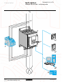
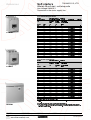
Options: Remote terminal, line chokes, protective
covers, documentation
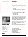
5HPRWHWHUPLQDO
The terminal can be mounted on the door of a wall-fixing or floor-standing enclosure.
It has the same signalling display and configuration buttons as the terminal
integrated in the starter. A switch to lock access to the menu is located at the rear of
the terminal.
The option comprises:
- the remote terminal
- a mounting kit containing a cover, screws and an IP 54 seal on the front panel
- a 3 m connecting cable with a 9-way SUB-D connector for connecting to the
terminal and an RJ45 connector for connecting to the Altistart 48
106770
1
ESC
3
ENT
4
Information is displayed in the form of codes or
values in three "7-segment" displays
Buttons for scrolling through the menus or
modifying values
"ESC": Button for exiting the menus
(cannot be used for validation purposes)
"ENT": Validation button for entering a menu or
confirming the new value selected
2
5HIHUHQFH
'HVFULSWLRQ
5HIHUHQFH
9: *
5HPRWHWHUPLQDO
9: *
:HLJKW
NJ
0.200
/LQHFKRNHV
The use of line chokes is recommended in particular when installing several
electronic starters on the same line supply. The values of the chokes are defined for
a voltage drop between 3% and 5% of the nominal line voltage.
Install the line choke between the line contactor and the starter.
5HIHUHQFHV
)RUVWDUWHUV
9DOXH
1RPLQDO
'HJUHHRI 5HIHUHQFH
RIWKH
FXUUHQW
SURWHFWLRQ
:HLJKW
FKRNH
ATS 48D17/
ATS 48D22/
ATS 48D32/ and48D38/
ATS 48D47/ and 48D62/
ATS 48D75/ to 48C14/
ATS 48C17/ to 48C25/
ATS 48C32/
ATS 48C41/ and 48C48/
ATS 48C59/ to 48M10/
ATS 48M12/
P+
$
1.7
0.8
0.6
0.35
0.17
0.1
0.075
0.045
0.024
0.016
15
30
40
70
150
250
325
530
1025
1435
NJ
IP 20
IP 20
IP 20
IP 20
IP 00
IP 00
IP 00
IP 00
IP 00
IP 00
9= /807
9= /87
9= /87
9= /87
9= /87
9= /87
9= /87
9= /87
9= /087
9= /087
2.100
4.100
5.100
8.000
14.900
24.300
28.900
37.000
66.000
80.000
1RWH/LQHFKRNHVZLWK,3GHJUHHRISURWHFWLRQPXVWEHILWWHGZLWKDSURWHFWLYHEDUWRSURWHFW
813095
SHUVRQQHODJDLQVWHOHFWULFDOFRQWDFW
3URWHFWLYHFRYHUVIRUSRZHUWHUPLQDOV
7REHXVHGZLWKWDJVFORVHG
5HIHUHQFHV
)RUVWDUWHUV
1XPEHURIFRYHUV
5HIHUHQFH
SHUVHW
ATS 48C14/ andATS 48C17/
ATS 48C21/, ATS 48C25/
and ATS 48C32/
/$ )
6 6 :HLJKW
NJ
/$ )
/$ )
0.250
0.250
7KHVWDUWHUVKDYHXQSURWHFWHGSRZHUWHUPLQDOV
1RWH
'RFXPHQWDWLRQ
'HVFULSWLRQ
)RUPDW
5HIHUHQFH
A5
A5
CD-ROM
99'('
:HLJKW
NJ
Altistart 48 user’s manual
Modbus user’s manual
Ethernet, FIPIO, DeviceNet,
Profibus DP user’s manuals
Schneider Electric
www.thianovation.com
99'('
'&,&'
0.150
0.150
0.150
17
3UHVHQWDWLRQ
TiNAMiCS CO.,LTD.
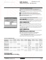
3RZHU6XLWHDGYDQFHGGLDORJXH
VROXWLRQV
The PowerSuite advanced dialogue solutions can be used for Schneider Electric
drives and starters. They enable communication with the product from a Pocket PC,
a PC or a dedicated terminal.
The solutions, with a Pocket PC or PC, enable files to be prepared for uploading to
the drives and the starters. The PowerSuite software creates its files ensuring
consistency between the configuration/adjustment functions of the product.
502945
3RZHU6XLWH3RFNHW3&
The Pocket PC can be used during preparation, programming, setup and
maintenance.
It comprises a Palm size PC terminal and corresponding connection accessories.
The software is integrated into a Windows CE environment, for which the operating
system language can be selected on ordering (English, French, German, Spanish,
Italian).
The software incorporates all the functions of integrated and remote terminals (drive
or starter configuration and adjustment, control, signalling, etc).
The Pocket PC can be used:
- alone to prepare and store configuration/adjustment files (integral battery or line
supply)
- connected to a PC for uploading configuration/adjustment files from the Pocket PC
to the PC or downloading from the PC to the Pocket PC
- connected to the drive or to the starter for configuration, adjustment or control
purposes or to upload a configuration/adjustment file from the Pocket PC to the
product or download a configuration/adjustment file from the product to the Pocket
PC
510886
3RZHU6XLWHVRIWZDUHZRUNVKRSIRU3&
The PowerSuite software workshop is used to set up a drive or a starter from a PC
in a Microsoft Windows 95, 98, NT4 or 2000 environment.
The software incorporates all the functions of integrated and remote terminals (drive
or starter configuration and adjustment, control, signalling, etc.) with assisted, guided
operator dialogue in 5 languages (English, French, German, Spanish, Italian) in a
Windows environment.
It can be used:
- alone to prepare and store drive or starter configuration files on diskette, CD-ROM
or hard disk
The drive or starter configuration can be printed out on paper or can be exported to
office automation software.
- connected to the drive or starter for configuration, adjustment or control purposes,
or for uploading a configuration/adjustment file from the PC to the product or
downloading from the product to the PC.
Connection is via a link between the drive or starter connector and the serial port on
the PC.
510888
0DJHOLVGLVSOD\XQLWZLWKPDWUL[VFUHHQ
The Magelis display unit with matrix screen can be used to monitor, diagnose and
adjust up to 8 Altivar 28, 58 or 58F drives in 5 languages (English, French, German,
Spanish, Italian).
It can display variables in alphanumeric format with European, Cyrillic or Asian fonts
in 4 sizes, or it can display icons or background images in black and white as well as
animations in barchart or gauge format.
The application is preloaded in the factory.
18
www.thianovation.com
Schneider Electric
5HIHUHQFHV
TiNAMiCS CO.,LTD.
3RZHU6XLWHDGYDQFHGGLDORJXH
VROXWLRQV
510099
3RFNHW3&
Several solutions are available to meet the needs of individual users:
# The complete Pocket PC
# The setup kit
# The connection kit
The complete Pocket PC is used to set up drives and starters and comprises:
5 1 Palm size "Jordana 525" PC terminal, with multilingual operating system , supplied with
PC synchronisation cable and mains power supply
5 1 CD-ROM containing the multilingual setup software which can be ordered separately
5 1 connection kit for the Palm size PC terminal
The setup kit comprises:
9: $
//
5 1 CD-ROM containing the multilingual setup software which can be ordered separately
5 1 connection kit for the Palm size PC terminal
The connection kit for the Palm size PC terminal comprises:
-2 connection cables, length 0.6 m, with 2 RJ45 connectors, marked respectively “PowerSuite”
and “ATV 28 before 09/01”
- 1 RJ45/9-way SUB-D adaptor for connecting ATV 58
and ATV 58F drives
- 1 converter marked “RS 232/RS 485 PPC” with one 9-way male SUB-D connector
and 1 RJ45 connector
'HVFULSWLRQ
8VHGZLWK
5HIHUHQFH
:HLJKW
ATS 48, ATV 28
ATV 58 and
ATV 58F
ATS 48, ATV 28
ATV 58 and
ATV 58F
ATS 48, ATV 28
ATV 58 and
ATV 58F
9: $
NJ
Complete Pocket PC
Setup kit
Connection kit for the
Palm size PC terminal
//
1.000
9: $
0.400
9: $
0.300
3RZHU6XLWHVRIWZDUHZRUNVKRSIRU3&
The software workshop is used to set up the drives and starters from a PC.
It comprises:
# 1 CD-ROM containing the multilingual setup software
# 1 connection kit for PC
The PC connection kit comprises:
-2 connection cables, length 3 m, with 2 RJ45 connectors, marked respectively “PowerSuite”
and “ATV 28 before 09/01”
-1 RJ45/9-way SUB-D adaptor for connecting ATV-58
and ATV-58F drives
-1 converter marked “RS 232/RS 485 PC” with one 9-way female SUB-D connector
and 1 RJ45 connector
'HVFULSWLRQ
8VHGZLWK
5HIHUHQFH
ATS 48, ATV 28
ATV 58, ATV 58F
ATS 48, ATV 28
ATV 58, ATV 58F
9: $
:HLJKW
NJ
1 CD-ROM containing the
multilingual setup software
Connection kit for PC
0.100
9: $
0.350
105080
0DJHOLVGLVSOD\XQLWZLWKPDWUL[VFUHHQ
The terminal has a backlit LCD with 8 lines of 40 characters.
The RS 485 connection kits for ATV 28 (VW3 A28301) and ATV 58 (VW3 A58306) drives, as
well as other connection accessories, should be ordered separately according to the number
and type of drives connected. Please consult your Regional Sales Office.
;%7 +0$
'HVFULSWLRQ
Magelis display unit with matrix screen
8VHG
ZLWK
5HIHUHQFH
ATV 28, ATV 58
and ATV 58F
;%7 +0$
8VHG
ZLWK
5HIHUHQFH
:HLJKW
NJ
0.600
$FFHVVRULHV
'HVFULSWLRQ
1 upgrade CD-ROM for multilingual setup ATS 48, ATV 28
software ATV 58 and
ATV 58F
Palm size “Jordana 525” PC terminal supplied ATS 48, ATV 28
ATV 58 and
with PC synchronisation cable and mains
ATV 58F
power supply
1 x 16 MB compact flash card containing the –
Pocket PC software for the Palm size
“Jordana 525” PC terminal
(QJOLVK)UHQFK*HUPDQ6SDQLVK,WDOLDQ
7RRUGHUWKHRSHUDWLQJV\VWHPLQ\RXUFKRVHQODQJXDJHUHSODFH
9: $
:HLJKW
NJ
0.100
9: $//
0.300
9: $
0.100
//E\(1IRU(QJOLVK)5IRU
)UHQFK'(IRU*HUPDQ63IRU6SDQLVKDQG,7IRU,WDOLDQ
7RILQGRXWDERXWWKHODWHVWDYDLODEOHYHUVLRQSOHDVHFRQVXOW\RXU5HJLRQDO6DOHV2IILFH
7KLVFDUGHQDEOHVWKHVRIWZDUHWREHUXQLPPHGLDWHO\ZLWKRXWV\QFKURQLVLQJZLWKD3&
Schneider Electric
www.thianovation.com
19
TiNAMiCS CO.,LTD.
6RIWVWDUWHUV
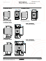
'LPHQVLRQV
Altistart 48 soft start - soft stop units
/WR$ 76'/
$76'
290
275
M6
10
150
4x 7
260
M6
270
4x 7
/WR$ 76&/
6,6
$76'
M6
190
=
100
=
M6
235
160
190
0D[LPXPFRQQHFWLRQFDSDFLW\ :
Earth connections: 10 mm2 (AWG 8)
Power terminals: 16 mm2 (AWG 8)
/WR$ 76&/
160
=
40
18 M6 20
159
4x 7
3/L2
5/L3
14
1
340
320
1/L1
1
2
5
:
Earth connections: 120 mm2 (busbar)
2
Power terminals: 95 mm (AWG 2/0)
0D[LPXPFRQQHFWLRQFDSDFLW\
=
10
$76&
0D[LPXPFRQQHFWLRQFDSDFLW\ :
Earth connections: 16 mm2 (AWG 4)
Power terminals: 50 mm2 (AWG 2/0)
5
116,5
5
38
162
62
200
265
$76&
9x 8
M6
62
/WR$ 76&/
=
66
35
136,5
M10
9x 12
3/L2
5/L3
4x 9
1
18
380
350
1/L1
10
2
5
:
Earth connections: 120 mm2 (busbar)
Power terminals: 240 mm2 (busbar)
0D[LPXPFRQQHFWLRQFDSDFLW\
=
250
5
5
136,5
196,5
70
320
265
Presentation:
pages 2 and 3
20
20
90
M10
90
Characteristics:
pages 4 and 5
www.thianovation.com
References:
pages 12 to 15
Schemes:
pages 24 to 29
Schneider Electric
TiNAMiCS CO.,LTD.
6RIWVWDUWHUV
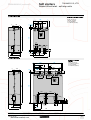
'LPHQVLRQVFRQWLQXHG
Altistart 48 soft start - soft stop units
$76&
/WR&/
0D[LPXPFRQQHFWLRQFDSDFLW\
=
300
115
120
Earth connections:
240 mm2 (busbar)
Power terminals:
2 x 240 mm2 (busbar)
=
115
127
165
20
5
4x 9
69
M10
3L2
5L3
610
670
5
1L1
5
5
1,5
40
58
165
216
300
$76&
0,25
M10
50,25
40
115
115
400
/WR0/
0D[LPXPFRQQHFWLRQ
=
350
350
FDSDFLW\ :
Earth connections:
2 x 240 mm2 (busbar)
Power terminals:
4 x 240 mm2 (busbar)
=
257
129
26
164
6x 9
209,5
26
18x 14
M10
26
20
170
2
5
26
223,5
180
850
228
204
26
26
5
26
24
26
5
5
116,5
196,5
60
M10
26
890
155
60
95
188
315
770
Presentation:
pages 2 and 3
Schneider Electric
Characteristics:
pages 4 and 5
www.thianovation.com
References:
pages 12 to 15
Schemes:
pages 24 to 29
21
:
TiNAMiCS CO.,LTD.
6RIWVWDUWHUV
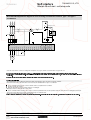
'LPHQVLRQVFRQWLQXHG
Altistart 48 soft start - soft stop units
&KRNHV
9=/807WR/87
9=/287WR/087
c
a
c
G
H
b
b
a
G
H
c1
c1
9=
/807
/87
/87
/87
D
E
F
F
120
150
180
180
150
180
215
215
80
120
130
150
75
100
100
130
G
60/80.5
75/106.5
85/122
85/122
H
52
76
76
97
Ø
6
7
7
7
9=
/87
/87
/87
/87
/087
/087
D
E
F
F
270
270
270
380
400
420
240
240
240
410
410
490
170
220
240
225
310
340
140
160
175
140
170
170
G
105/181
105/181
105/181
310
310
310
H
96
125
138
95
125
125
Ø
11.5
11.5
11.5
9
9
9
0RXQWLQJWKHUHPRWHWHUPLQDO
9: *
55,6
52
79,6
24
A
4xØ3,5
Presentation:
pages 2 and 3
22
Ø36
Characteristics:
pages 4 and 5
www.thianovation.com
References:
pages 12 to 15
Schemes:
pages 24 to 29
Schneider Electric
6RIWVWDUWHUV
0RXQWLQJ
TiNAMiCS CO.,LTD.
Altistart 48 soft start - soft stop units
100 mm
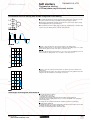
0RXQWLQJUHFRPPHQGDWLRQV
# Install the Altistart vertically, at ± 10°.
# Do not place the Altistart close to or above heating elements.
# Leave sufficient free space to ensure that the air required for cooling purposes can
circulate from the bottom to the top of the unit.
The IP 00 version of the Altistart 48 must be fitted with a protective bar to
protect personnel against electrical contact.
Protective covers are available for the ATS 48C14/ to ATS 48C32/. They should be
ordered separately.
&DXWLRQ
50
mm
100 mm
50
mm
0RXQWLQJLQDPHWDOZDOOIL[LQJRUIORRUVWDQGLQJHQFORVXUHZLWKGHJUHHRISURWHFWLRQ,3RU,3
# Observe the mounting recommendations above.
# To ensure proper air circulation in the starter:
5 Fit ventilation grilles
5 Ensure that there is sufficient ventilation. If there is not, install forced ventilation
with a filter. The openings and/or fans must provide a flow rate at least equal to that
of the starter fans (see the table below)
# Use special filters with IP 54 protection.
)DQIORZUDWHGHSHQGLQJRQWKHVWDUWHUUDWLQJ
$76VWDUWHU
)ORZUDWHP KRXU
ATS48 D32/ and D38/
ATS48 D47/
ATS48 D62/ to C11/
ATS48 C14/ and C17/
ATS48 C21/ to C32/
ATS48 C41/ to C66/
ATS48 C29/ to M12/
14
28
86
138
280
600
1200
0HWDOZDOOIL[LQJRUIORRUVWDQGLQJHQFORVXUHZLWK,3GHJUHHRISURWHFWLRQ
For non-ventilated Altistart units (ATS 48D17/ and 48D22/), install a fan 650 mm
below the starter to circulate the air inside the enclosure in order to avoid hot spots.
&DOFXODWLQJWKHVL]HRIWKHHQFORVXUH
0D[LPXPWKHUPDOUHVLVWDQFH5WK&:
θ – θe
Rth = ---------------P
θ = maximum temperature inside enclosure in °C
θe = maximum external temperature in °C
P = total power dissipated in the enclosure in W
The starter/motor combinations on pages 12 and 13 can only be used in ambient
temperatures 640°C.
For temperatures between 40°C and 60°C, derate the maximum permanent current
of the starter by 2% for every degree above 40°C.
Power dissipated by the starter: see pages 12 and 13.
If the starts are infrequent, it is advisable to bypass the Altistart at the end of starting
in order to reduce heat dissipation.
The power dissipated will then be between 15 and 30 W.
Add the power dissipated by the other equipment components.
(IIHFWLYHH[FKDQJHVXUIDFHDUHDRIHQFORVXUH6P
(sides + top + front panel if wall-mounted)
K
S = ---------Rth
K is the thermal resistance per m2 of casing
For ACM type metal enclosures: K = 0.12 with internal fan, K = 0.15 without fan
Do not use insulated enclosures as they have a poor level of conductivity.
&DXWLRQ
Presentation:
pages 2 and 3
Schneider Electric
Characteristics:
pages 4 and 5
www.thianovation.com
References:
pages 12 to 15
Schemes:
pages 24 to 29
23
6RIWVWDUWHUV
6FKHPHV
TiNAMiCS CO.,LTD.
Altistart 48 soft start - soft stop units
13
5HFRPPHQGHGDSSOLFDWLRQGLDJUDPIRUQRQUHYHUVLQJXQLWZLWKOLQHFRQWDFWRUW\SHDQGW\SH
FRRUGLQDWLRQ
14
5
3
1
Q1
Q1
Emergency stop
2
1
2
T1
1
2
S2
KM1
14
1
13
6
4
2
S1
R1A
5
3
1
A1
(2)
R1C
A1
6
4
2
KM1
Q3
KM1
A2
(1)
R3C
R3A
R2C
R2A
R1C
PTC2
R1A
PTC1
COM
AO1
LO2
LO1
CL2
CL1
LO+
+24V
LI4
53
LI3
5/L3
6/T3
RUN
3/L2
4/T2
STOP
1/L1
A1
2/T1
(3)
W1
V1
U1
54
KM1
M1
3
Select the components to connect, according to the descriptions on page 25, from the association tables on pages 30 to 39.
)RUW\SHFRRUGLQDWLRQDFFRUGLQJWR,(&LQVWDOOIDVWDFWLQJIXVHVWRHQVXUHWKDWWKHVWDUWHUZLOOEHSURWHFWHGLQWKHHYHQWRIDVKRUWFLUFXLW
$VVLJQUHOD\5DVWKHLVRODWLQJUHOD\%HZDUHRIWKHRSHUDWLQJOLPLWVRIWKHFRQWDFWVVHH&KDUDFWHULVWLFVSDJHIRUH[DPSOHZKHQFRQQHFWLQJWRKLJKUDWLQJ
FRQWDFWRUV
,QVHUWDWUDQVIRUPHULIWKHOLQHYROWDJHLVGLIIHUHQWWRWKDWGHILQHGIRUWKHFRQWUROFLUFXLWVHHSDJH
7\SHVRIFRRUGLQDWLRQ
The standard defines tests for different current levels which are designed to expose the device to extreme conditions.
Based on the state of the components after a short-circuit test, the standard defines 2 types of coordination.
# Type 1 coordination: Damage to the contactor and the starter is acceptable under 2 conditions:
5 No risk is posed to the operator
5 Elements other than the contactor and the starter are not damaged
Maintenance must be carried out after a short-circuit.
# Type 2 coordination: Minor soldering of the contactor contacts is permissible if they can be separated easily. The starter must not be damaged beyond repair.
The protection and control devices remain operational after type 2 coordination tests.
Once the fuses have been replaced, check the contactor.
1RWH7KHVWDUWHUZLOOSURWHFWWKHPRWRUDQGWKHFDEOHVDJDLQVWRYHUORDGV,IWKLVSURWHFWLRQIXQFWLRQLVGLVDEOHGH[WHUQDOWKHUPDOSURWHFWLRQPXVWEHSURYLGHG
Presentation:
pages 2 and 3
24
Characteristics:
pages 4 to 7
www.thianovation.com
References:
pages12 to 15
Dimensions:
pages 20 to 23
Schneider Electric
TiNAMiCS CO.,LTD.
6RIWVWDUWHUV
6FKHPHVFRQWLQXHG
Altistart 48 soft start - soft stop units
Q1
14
5
3
1
13
5HFRPPHQGHGDSSOLFDWLRQGLDJUDPIRUQRQUHYHUVLQJXQLWZLWKVWDUWHUOLQHDQGE\SDVVFRQWDFWRUVW\SH
DQGW\SHFRRUGLQDWLRQ
Q1
6
5
4
3
1
2
Emergency stop
1
2
1
2
T1
1
R2A
A1
2
R1A
(2)
R2C
R1C
Q3
A1
A1
6
4
2
KM1
A2
KM1
A2
KM3
(1)
CL2
CL1
5/L3
5
6
3/L2
3
4
A1
1/L1
1
2
(3)
R3C
R3A
R2C
R2A
R1C
R1A
PTC2
PTC1
COM
AO1
LO2
LO1
LO+
+24V
LI4
LI3
RUN
STOP
2/T1
A2
4/T2
B2
6/T3
C2
KM3
S2
S1
+ 24 V
STOP
+ 24 V
RUN
STOP
M1
3
W1
V1
U1
3-wire control S1
2-wire control When controlled via a PC or PLC, the
STOP input remains active
Select the components to connect, according to the descriptions below, from the association tables on pages 30 to 39.
)RUW\SHFRRUGLQDWLRQDFFRUGLQJWR,(&LQVWDOOIDVWDFWLQJIXVHVWRHQVXUHWKDWWKHVWDUWHUZLOOEHSURWHFWHGLQWKHHYHQWRIDVKRUWFLUFXLW
$VVLJQUHOD\5DVWKHLVRODWLQJUHOD\%HZDUHRIWKHRSHUDWLQJOLPLWVRIWKHFRQWDFWVVHH&KDUDFWHULVWLFVSDJHIRUH[DPSOHZKHQFRQQHFWLQJWRKLJKUDWLQJ
FRQWDFWRUV
,QVHUWDWUDQVIRUPHULIWKHOLQHYROWDJHLVGLIIHUHQWWRWKDWGHILQHGIRUWKHFRQWUROFLUFXLWVHHSDJH
ZLUHDQGZLUHFRQWUROVHHSDJH
&RPSRQHQWVWRFRQQHFWGHSHQGLQJRQWKHW\SHVRIFRRUGLQDWLRQDQGYROWDJHV
'HVLJQDWLRQ
'HVFULSWLRQ
0
Motor
Starter (standard applications and severe applications)
Circuit-breaker or switch/fuses
3 FA fuses
Contactor
Control (separate parts XB2 or XB2 M)
$
4
4
.0.0
66
Presentation:
pages 2 and 3
Schneider Electric
Characteristics:
pages 4 to 7
www.thianovation.com
References:
pages12 to 15
Dimensions:
pages 20 to 23
25
TiNAMiCS CO.,LTD.
6RIWVWDUWHUV
6FKHPHVFRQWLQXHG
Altistart 48 soft start - soft stop units
5HFRPPHQGHGDSSOLFDWLRQGLDJUDPIRUFRQQHFWLRQWRWKHPRWRUGHOWDWHUPLQDOVQRQUHYHUVLQJIUHHZKHHO
VWRSZLWKVWDUWHUOLQHDQGE\SDVVFRQWDFWRUVW\SHDQGW\SHFRRUGLQDWLRQ
14
5
6
5
2
1
2
- T1
1
R2A
A1
2
(3)
R2C
a
M1
3
A2
A2
R2C
R2A
R1C
R1A
PTC2
PTC1
AO1
COM
LO2
LO1
CL2
LO+
+24V
STOP
+24V
RUN
STOP
3-wire control
V2
- KM1
S2
S1
U1
+24V
CL1
LI4
LI3
RUN
2/T1
A2
4/T2
B2
6/T3
C2
STOP
5/L3
5
6
3/L2
3
4
1/L1
1
2
(4)
- KM3
A1
A1
- KM3
(2)
A1
R1C
6
4
2
Q3
U2
R1A
R3C
2
4
3
1
1
(1) - KM1
W2
Emergency stop
- S3
- Q1
R3A
3
1
- Q1
13
This type of wiring enables the starter rating to be reduced.
ATS 48///Q
V1
W1
S1
2-wire control
When controlled via a PC or PLC, the
STOP input remains active.
Select the components to connect according to the descriptions on page 27 and the association tables on pages 30 to 39.
$OLQHFRQWDFWRUPXVWEHXVHGLQWKHVHTXHQFH
)RUW\SHFRRUGLQDWLRQDFFRUGLQJWR,(&LQVWDOOIDVWDFWLQJIXVHVWRHQVXUHWKDWWKHVWDUWHUZLOOEHSURWHFWHGLQWKHHYHQWRIDVKRUWFLUFXLW
5PXVWEHDVVLJQHGDVWKHLVRODWLQJUHOD\WRFRQWUROFRQWDFWRU.0%HZDUHRIWKHRSHUDWLQJOLPLWVRIWKHFRQWDFWV
VHH&KDUDFWHULVWLFVSDJHIRUH[DPSOHZKHQFRQQHFWLQJWRKLJKUDWLQJFRQWDFWRUV
,QVHUWDWUDQVIRUPHULIWKHOLQHYROWDJHLVGLIIHUHQWWRWKDWGHILQHGIRUWKHFRQWUROFLUFXLWVHHSDJH
ZLUHDQGZLUHFRQWUROVHHSDJH
7\SHVRIFRRUGLQDWLRQ
The standard defines tests for different current levels which are designed to expose the device to extreme conditions.
Based on the state of the components after a short-circuit test, the standard defines 2 types of coordination.
# Type 1 coordination: damage to the contactor and the starter is acceptable under 2 conditions:
5 No risk is posed to the operator
5 Elements other than the contactor and the starter are not damaged
Maintenance must be carried out after a short-circuit.
# Type 2 coordination: Minor soldering of the contactor contacts is permissible if they can be separated easily. The starter must not be damaged beyond repair.
The protection and control devices remain operational after type 2 coordination tests.
Once the fuses have been replaced, check the contactor.
1RWH7KHVWDUWHUZLOOSURWHFWWKHPRWRUDQGWKHFDEOHVDJDLQVWRYHUORDGV,IWKLVSURWHFWLRQIXQFWLRQLVGLVDEOHGH[WHUQDOWKHUPDOSURWHFWLRQPXVWEHSURYLGHG
Presentation:
pages 2 and 3
26
Characteristics:
pages 4 to 7
www.thianovation.com
References:
pages12 to 15
Dimensions:
pages 20 to 23
Schneider Electric
TiNAMiCS CO.,LTD.
6RIWVWDUWHUV
6FKHPHVFRQWLQXHG
Altistart 48 soft start - soft stop units
1
3
5
2
4
6
5HFRPPHQGHGDSSOLFDWLRQGLDJUDPIRU/63+63PRWRUQRQUHYHUVLQJZLWKVWDUWHUOLQHDQGE\SDVV
FRQWDFWRUV
5
3
1
- Q1
1
2
1
2
- T1
1
220
2
0
6
4
2
- KM1
Q3
(1)
R3C
R3A
R2C
R2A
R1C
R1A
PTC2
PTC1
COM
AO1
LO2
LO1
LO+
+24V
CL2
LI4
CL1
LI3
2/T1
A2
4/T2
B2
6/T3
C2
RUN
- KM3
STOP
5/L3
5
6
3/L2
3
4
A1
1/L1
1
2
(2)
(3)
KA1
- KM5
KM2
- KM2
U2
V2
W2
U1
V1
M1
3
W1
Select the components to connect, according to the descriptions below, from the association tables on pages 30 to 39.
)RUW\SHFRRUGLQDWLRQDFFRUGLQJWR,(&LQVWDOOIDVWDFWLQJIXVHVWRHQVXUHWKDWWKHVWDUWHUZLOOEHSURWHFWHGLQWKHHYHQWRIDVKRUWFLUFXLW
,QVHUWDWUDQVIRUPHULIWKHOLQHYROWDJHLVGLIIHUHQWWRWKDWGHILQHGIRUWKHFRQWUROFLUFXLWVHHSDJH
$VVLJQORJLFLQSXW/,WRDFWLYDWHWKHDGMXVWPHQWIXQFWLRQVRIWKH
QGPRWRU
$VVLJQUHOD\5DVWKHLVRODWLQJUHOD\%HZDUHRIWKHRSHUDWLQJOLPLWVRIWKHFRQWDFWVVHH&KDUDFWHULVWLFVSDJHIRUH[DPSOHZKHQFRQQHFWLQJWRKLJKUDWLQJ
FRQWDFWRUV
220 V
KM1
Emergency stop
1
Q1
A1
2
R2A
S1
(4)
R2C
S4
KM5
KM2
A1
R1A
S2
(4)
KA1
KA1
KM5
R1C
S3
KM1
KM2
KM2
KM5
KM3
S4 = 1 : low speed
= 2 : high speed
0
&RPSRQHQWVWRFRQQHFWGHSHQGLQJRQWKHW\SHVRIFRRUGLQDWLRQDQGYROWDJHV
'HVLJQDWLRQ
'HVFULSWLRQ
0
Motor
Starter (standard applications and severe applications)
Circuit-breaker or switch/fuses
3 FA fuses
Contactors and relays
Control (separate parts XB2 or XB2 M)
$
4
4
.0.0.0.0.$
666
Schneider Electric
www.thianovation.com
27
TiNAMiCS CO.,LTD.
6RIWVWDUWHUV
6FKHPHVFRQWLQXHG
Altistart 48 soft start - soft stop units
5HFRPPHQGHGDSSOLFDWLRQGLDJUDPIRUVWDUWLQJDQGGHFHOHUDWLQJVHYHUDOPRWRUVFDVFDGHGZLWKDVLQJOH
$OWLVWDUWQRQUHYHUVLQJDQGOLQHFRQWDFWRU
7KHGLDJUDPLVJLYHQDVDQH[DPSOHRQO\)RUPRUHGHWDLOVUHIHUWRWKH$OWLVWDUWXVHU
VPDQXDO
KA
KALI
KAT
KALIT
KALIT
5
3
1
A
STOP
LI3
RUN
6
5
CL2
4
3
A1
CL1 +24V
2
1
- Q1
(2)
1
2
1
2
- T1
1
2
6
4
2
- KM1
B
1
3
5
2
4
6
5
3
4
6
5
3
2
M2
3
4
6
Wn
Mi
3
Motor 1
Vn
2
6
M1
Un
4
W2
2
U2
V2
6
W1
- Qn1
4
2
- KMn2
1
6
4
6
5
2
4
3
- KMn1
- Q21
U1
1
5
3
1
3
5
3
1
2
1
6
6
5
4
4
- KM22
V1
- Q11
- KM21
2
2
3
- KM12
1
- KM11
5
1
6/T3 5/L3
5
4/T2 3/L2
3
1
A1
2/T1 1/L1
- Q3
(1)
Mn
3
Motor 2
3
Motor i
Motor n
Select the components to connect, according to the designations below, from the association tables on pages 30 to 39.
)RUW\SHFRRUGLQDWLRQDFFRUGLQJWR,(&LQVWDOOIDVWDFWLQJIXVHVWRHQVXUHWKDWWKHVWDUWHUZLOOEHSURWHFWHGLQWKHHYHQWRIDVKRUWFLUFXLW
,QVHUWDWUDQVIRUPHULIWKHOLQHYROWDJHLVGLIIHUHQWWRWKDWGHILQHGIRUWKHFRQWUROFLUFXLWVHHSDJH
,PSRUWDQW
# One Altistart 48 logic input must be configured as a "cascading" input.
# In the event of a fault, it will not be possible to decelerate or brake any motors that may be running at that time.
# Adjust the thermal protection of each circuit-breaker Qn1 for the corresponding nominal motor current.
&RPSRQHQWVWRFRQQHFWGHSHQGLQJRQWKHW\SHVRIFRRUGLQDWLRQDQGYROWDJHV
'HVLJQDWLRQ
'HVFULSWLRQ
000L0Q
Motor
Starter (standard applications and severe applications)
Contactor
Circuit-breaker or switch/fuses
3 FA fuses
Thermal magnetic circuit-breakers
Control (separate parts XB2 or XB2 M)
$
.0.0.0L.0Q
4
4
444Q
.$.$7.$/,.$/,7
Presentation:
pages 2 and 3
28
Characteristics:
pages 4 to 7
www.thianovation.com
References:
pages12 to 15
Dimensions:
pages 20 to 23
Schneider Electric
TiNAMiCS CO.,LTD.
6RIWVWDUWHUV
6FKHPHVFRQWLQXHG
Altistart 48 soft start - soft stop units
5HFRPPHQGHGDSSOLFDWLRQGLDJUDPIRUVWDUWLQJDQGGHFHOHUDWLQJVHYHUDOPRWRUVFDVFDGHGZLWKDVLQJOH
$OWLVWDUWQRQUHYHUVLQJDQGOLQHFRQWDFWRUFRQWLQXHG
0RWRUQFRQWURO
A...
C
(n-1) contacts
KM11
KM21
ARn
SHUNT
KT
KMi1
KMn1
BPMn
KAT
ACDEC
KMn2
BPAn
BPAn
KAMn
KMn2
KMn1
KAMn
KMn2
SHUNT
ART
ARn
KAMn
ARn
KMn1
ARn
KMn1
KMn2
B...
D
&DVFDGHFRQWURO
C
n contacts
MST
KM1
MHT
AR1
AR2
ARi
ARn
Q11
n contacts
n contacts
Q21
A1
K
KA
KALI
R1C
KALIT
KT
KALIT
ART
KAMi
KAMn
Qi1
R2C
(3)
R1A
KAT
KAM1 KAM2
ACDEC
R2A
SHUNT
Qn1
KM1
KA
K
KALI
D
$VVLJQUHOD\5DVWKHLVRODWLQJUHOD\%HZDUHRIWKHRSHUDWLQJOLPLWVRIWKHFRQWDFWVVHH&KDUDFWHULVWLFVSDJHIRUH[DPSOHZKHQFRQQHFWLQJWRKLJKUDWLQJ
FRQWDFWRUV
BPMn: "Run" button motor n
BPAn: "Stop" button motor n
MST: General "Run" button
MHT: General "Stop" button
Presentation:
pages 2 and 3
Schneider Electric
Characteristics:
pages 4 to 7
www.thianovation.com
References:
pages12 to 15
Dimensions:
pages 20 to 23
29
6RIWVWDUWHUV
)XQFWLRQVFRQWLQXHG
TiNAMiCS CO.,LTD.
Altistart 48 soft start - soft stop units
$GMXVWPHQWIXQFWLRQV
# 1RPLQDOPRWRUFXUUHQW(maximum permanent current)
The nominal current of the starter can be adapted to the nominal motor current
indicated on the rating plate.
Adjustment range: 0.4 to 1.3 times the starter nominal current.
#
/LPLWLQJFXUUHQW
The maximum starting current can be adjusted.
Adjustment range: 150% to 700% of the nominal motor current set and limited to
500% of the maximum permanent current defined for the starter rating.
#
$FFHOHUDWLRQUDPSWLPH
During the starting phase, the Altistart 48 applies a torque ramp to the motor. The
time (ACC) set corresponds to the time taken by the ramp to reach the nominal
torque (starting at 0). Adjustment range: 1 to 60 s.
% Cn
100
#
80
,QLWLDOVWDUWLQJWRUTXH
The initial torque tq0 applied to the motor can be used to instantly overcome any
resistive starting torque. Adjustment range: 0 to 100% of the nominal motor torque.
60
tq0 = 40
40
20
0
0
t
ACC
$FFHOHUDWLRQUDPSGXULQJWLPH$&&ZLWKLQLWLDOVWDUWLQJ
WRUTXH,T
RIWKHQRPLQDOPRWRUWRUTXH
#
6HOHFWLRQRIWKHW\SHRIVWRS
Three types of stop are available for selection:
5
5
0RWRUVWRSE\GHFHOHUDWLRQYLDWRUTXHFRQWUROSXPSDSSOLFDWLRQThis type of
stop enables a centrifugal pump to be decelerated gradually on a ramp in order to
avoid a sudden stop. It can be used to dampen the hydraulic transient in order to
significantly reduce pressure surges.
The deceleration ramp time (dEC) can be adjusted.
During deceleration, the pump flow rate decreases and becomes negligible at a
certain speed. To continue to decelerate would serve no purpose. A torque threshold
(EdC) can be set at which the motor will change to freewheel stop mode, avoiding
the unnecessary heating of the motor and the pump.
% Cn
100
80
End
deceleration
Fin of
decontrolled
décélération
controlée
60
EdC
40
)UHHZKHHOPRWRUVWRS
20
0
t
dEC
'HFHOHUDWHGVWRSE\WRUTXHFRQWUROGXULQJWLPHG(&ZLWK
WKUHVKROG(GFIRUFKDQJLQJWRIUHHZKHHOVWRSPRGH
(GF
RIQRPLQDOPRWRUWRUTXH
5
'\QDPLFEUDNLQJPRWRUVWRSDSSOLFDWLRQVWRSSLQJKLJKLQHUWLDPDFKLQHV
This type of stop will decelerate the motor if there is considerable inertia.
The braking torque level (brc) can be adjusted. The dynamic braking time (T1)
corresponds to the time taken to decelerate from 100% to 20% of the nominal motor
speed. To improve braking at the end of deceleration, the starter injects a d.c. current
for an adjustable period of time (T2).
100 %
brc = 20
brc = 100
20 %
0
T1
T2
t
'\QDPLFEUDNLQJVWRSVIRUGLIIHUHQWEUDNLQJWRUTXHOHYHOVEUF
Schneider Electric
www.thianovation.com
41
6RIWVWDUWHUV
)XQFWLRQVFRQWLQXHG
TiNAMiCS CO.,LTD.
Altistart 48 soft start - soft stop units
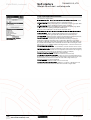
3URWHFWLRQIXQFWLRQV
t(s)
10000
The Altistart 48 offers functions for protecting the motor and the machine.
#
1000
100
Class
30
25
20
15
10
10
10 A
2
1
0,5
1,12
2,00
3,00
4,00
5,00
6,00
7,00
Id/In
8,00
0RWRUWKHUPDOSURWHFWLRQFXUYHVFROG
t(s)
10000
&DOFXODWHGPRWRUWKHUPDOSURWHFWLRQ
The starter continuously calculates the temperature rise of the motor based on the
nominal current which has been set and the actual current absorbed. In order to
adapt the Altistart to individual motors and applications, several protection classes
are offered in accordance with standard IEC 60947-4-2:
class 30, class 25, class 20 (severe application), class 15, class 10 (standard
application), class 10 A, sub-class 2.
Different protection classes are defined for the starting capacities of the motor:
- cold start without thermal fault (corresponding to a stabilised motor thermal state,
motor switched off)
- warm start without thermal fault (corresponding to a stabilised motor thermal
state, at nominal power)
The motor thermal protection function can be disabled.
After the motor has stopped or the starter has been switched off, the thermal state is
calculated even if the control circuit is not energised. The Altistart thermal control
prevents the motor from restarting if the temperature rise is too high. If special motors
are used which do not have thermal protection via curves, provide external thermal
protection via probes or thermal overload relays.
The starter is factory-set to protection class 10.
The tripping curves are based on the relationship between the starting current Is and
the (adjustable) nominal motor current In.
Trip time (cold)
Trip time for a standard application (class 10)
Is = 3 In
Is = 4 In
Is = 5 In
46 s
23 s
15 s
Trip time for a severe application (class 20)
Is = 3.5 In
Is = 4 In
Is = 5 In
63 s
48 s
29 s
Trip time (warm)
Trip time for a standard application (class 10)
Is = 3 In
Is = 4 In
Is = 5 In
23 s
12 s
7.5 s
Trip time for a severe application (class 20)
Is = 3.5 In
Is = 4 In
Is = 5 In
32 s
25 s
15 s
#
5HVHWPRWRUWKHUPDOVWDWH
Activating the function resets the motor thermal state calculated by the starter to
zero.
1000
#
0RWRUWKHUPDOSURWHFWLRQZLWK37&SUREHV
The starter integrates the processing of PTC probes, thus avoiding the use of an
external device. The "PTC probe thermal overshoot" fault or alarm can be indicated
using a configurable logic output or displayed via the serial link. The function can be
disabled.
Note: The "PTC probe protection" and "calculated motor thermal protection"
functions are independent and can be active simultaneously.
100
Class
10
30
25
20
15
10
# 6WDUWHUYHQWLODWLRQ: The cooling fan on the starter is switched on as soon as the
heatsink temperature reaches 50°C. It is switched off when the temperature returns
to 40°C.
#
6WDUWHUWKHUPDOSURWHFWLRQ
The starter is protected against thermal overloads by an analogue thermal probe.
10 A
1
0,5
1,12
2,00
3,00
4,00
5,00
6,00
7,00
2 Id/In
8,00
0RWRUWKHUPDOSURWHFWLRQFXUYHVZDUP
42
www.thianovation.com
Schneider Electric
6RIWVWDUWHUV
)XQFWLRQVFRQWLQXHG
TiNAMiCS CO.,LTD.
Altistart 48 soft start - soft stop units
3URWHFWLRQIXQFWLRQVFRQWLQXHG
# 0RWRUXQGHUORDGSURWHFWLRQ
C
(Cn) 100 %
LUL + 10 %
LUL
t < tUL
tUL
20 %
ULL t
0RWRUXQGHUORDGGHWHFWLRQ8//
The starter detects a motor underload if the motor torque falls below a preset torque
threshold (LUL) for a specific (adjustable) period of time (tUL).
The motor underload threshold can be set between 20% and 100% of the nominal
motor torque. The permissible underload duration can be set between 1 and 60 s.
The detection function can trigger an alarm or a fault. The detection function can be
disabled. The "motor underload detected" alarm can be indicated by a configurable
logic output and/or displayed via the serial link in the state of the starter.
The "motor underload detected" fault (ULF) locks the starter and can be displayed
via the serial link.
#
([FHVVLYHDFFHOHUDWLRQWLPHSURWHFWLRQ
This protection function can be used to detect a start which takes place in adverse
conditions. Examples of such conditions include a locked rotor or a motor unable to
reach its nominal rotation speed.
If the start duration is greater than the value set (between 10 and 999 s),
the drive changes to fault mode. The function can be disabled.
I
300 %
#
LOC
LOC -10 %
50 %
t < tOL
tOL
t
OIL
0RWRURYHUFXUUHQWGHWHFWLRQ2,/
&XUUHQWRYHUORDGSURWHFWLRQ
The starter detects a current overload if the motor current exceeds a preset
overcurrent threshold (LOC) for a specific (adjustable) period of time (tOL).
The overcurrent threshold can be set between 50% and 300% of the nominal motor
current.
The permissible overcurrent duration can be set between 0.1 and 60 s.
This function is only active in steady state.
The detection function can trigger an alarm or a fault. It can also be disabled.
The "current overload detected" alarm can be indicated by a configurable logic output
and/or displayed via the serial link.
The "current overload detected" fault (OLC) locks the starter and can be displayed
via the serial link in the state of the starter.
#
3URWHFWLRQDJDLQVWOLQHSKDVHLQYHUVLRQ
This function can be used to detect the direction of rotation of the motor phases and,
if it is enabled, to indicate a fault when the direction of rotation is reversed.
#
7LPHEHIRUHUHVWDUWLQJ
This function can be used to avoid several consecutive starts which may cause:
- the thermal overheating of the application, which is not permitted
- a thermal fault which will require maintenance work to be carried out
- overcurrents (if the direction of rotation is reversed) or repeats (run/stop
commands)
Following a stop command, the motor can only restart once the preset time delay has
elapsed.
The motor is restarted once the time delay has elapsed if a run command is still valid
or if a new run command is sent.
Adjustment range: 0 to 999 s.
#
&RQILJXULQJWKHVWDUWHURYHUORDGDQGXQGHUORDGZLWK
0RWRUSKDVHORVVGHWHFWLRQ
The function is used to adjust the sensitivity of the protection function in order to
detect a loss of current or a low current in one of the three motor phases for at least
0.5 s or in all three motor phases for at least 0.2 s. The value of the minimum current
level can be set between 5% and 10% of the starter nominal current.
3RZHU6XLWHRQD3&
#
$XWRPDWLFUHVWDUW
After locking on a fault, the function permits up to six restart attempts at intervals of
60 s if the fault has disappeared and the run commands are still present. After the
sixth attempt, the starter will remain locked and the fault will have to be reset before
a restart is permitted.
If the function is active, the fault relay remains activated if line phase loss, motor
phase loss or line frequency out of tolerance faults are detected. This function can
only be used in 2-wire control.
Schneider Electric
www.thianovation.com
43
6RIWVWDUWHUV
)XQFWLRQVFRQWLQXHG
TiNAMiCS CO.,LTD.
Altistart 48 soft start - soft stop units
$GYDQFHGDGMXVWPHQWIXQFWLRQV
# 7RUTXHOLPLW
Designed primarily for high inertia and constant torque conveyor applications , the
function restricts the torque ramp reference to the preset value.
For example, the function can be used to limit the torque to a constant value
throughout the starting period.
Adjustment range: 10% to 200% of the nominal motor torque.
#
Cd
100 %
Un
Torque
Rampe ramp
de couple
50 %
Un
100 ms
9ROWDJHERRVWOHYHO
The function can be used to avoid any "starting" torque (phenomenon caused by
friction on stopping or by mechanical play). When a run command is sent, the starter
applies a fixed voltage to the motor for a limited period of time before starting. The
function can be disabled.
The voltage setting value varies between 50% and 100% of the nominal motor
voltage.
C
t
$SSOLFDWLRQRIDYROWDJHERRVWHTXDOWRRIWKH
QRPLQDOPRWRUYROWDJH
#
&RQQHFWLQJWKHVWDUWHUWRWKHPRWRUGHOWDWHUPLQDO
#
7HVWRQORZSRZHUPRWRU
ATS48///Q starters connected to motors with delta terminals can be wired in series
in the motor windings. This type of connection reduces the current in the starter by a
ratio of , which enables a lower rating starter to be used. The nominal current and
limiting current settings as well as the current displayed during operation are on-line
values and are indicated on the motor. For this application, the braking or
decelerating stop functions are inactive. Only freewheel stopping is possible.
The adjustment range of the nominal motor current and the limiting current are
multiplied by if the function is selected.
This function is not compatible with the following functions: motor phase loss
detection, motor preheating, cascade, decelerated stop and dynamic braking.
Use the scheme recommended on page 26 for this type of configuration.
This function can be used to test a starter on a motor whose power is very much
lower that of the starter. It can be used for example to check the electrical wiring of
a device.
The function is automatically cancelled when the starter is switched off.
The next time the starter is switched on, the starter returns to its initial configuration.
#
$FWLYDWLRQRIWKHFDVFDGHIXQFWLRQ
This function can be used to start and decelerate several cascaded motors with a
single starter.
In order to gain maximum benefit from torque control, it is advisable to use motors
with powers between 0.5 and 1 times the power of the motor.
The wiring diagram for the cascaded motor function is shown on page 28.
This function is not compatible with the following functions: motor preheating and
connection to the motor delta terminal.
# /LQHIUHTXHQF\
The following frequencies can be selected for the function:
- 50 Hz. The frequency fault monitoring tolerance is ± 20%.
- 60 Hz. The frequency fault monitoring tolerance is ± 20%.
- Automatic detection of the line frequency by the starter The frequency fault
monitoring tolerance is ± 6%.
5 50 Hz and 60 Hz are recommended if the power supply is provided by a generating
set, given their high tolerance.
#
5HVHWN:KRUWKHRSHUDWLQJWLPH
Sets the value of the power in kW/h or the operating time value to 0. The calculation
of the values is updated once the reset command has been sent.
# 5HWXUQWRIDFWRU\VHWWLQJV
The function can be used to reset each setting to its initial value (starter factory
setting, see page 40).
44
www.thianovation.com
Schneider Electric
)XQFWLRQVFRQWLQXHG
6RIWVWDUWHUV
TiNAMiCS CO.,LTD.
Altistart 48 soft start - soft stop units
QGPRWRUDGMXVWPHQWIXQFWLRQV
In order to access the 2nd motor adjustment functions, one logic input must be
assigned to the second set of motor parameters function. The adjustment functions
and ranges are identical for both sets of motor parameters.
The settings are as follows (see page 41):
- Nominal motor current
- Limiting current
- Acceleration ramp time
- Initial starting torque
- Deceleration ramp time
- Threshold for changing to freewheel stop mode at the end of deceleration
- Maximum torque limit
&RPPXQLFDWLRQIXQFWLRQV
The Altistart 48 is supplied with an RS 485 multidrop serial link with Modbus protocol
as standard. The serial link is configured in the Communication menu using:
5 The address of the starter, which can be set between 0 and 31
5 The communication speed, which can be set at: 4800, 9600 or 19200 bps
5 The format of the communication data. The following formats can be selected:
- 8 data bits, odd parity, 1 stop bit
- 8 data bits, even parity, 1 stop bit
- 8 data bits, no parity, 1 stop bit
- 8 data bits, no parity, 2 stop bits
5 The time-out, which can be set between 1 and 60 s
3RZHU6XLWHDGYDQFHGGLDORJXHVROXWLRQV
The PowerSuite advanced dialogue solutions (see pages 18 and 19) offer the
following advantages:
5 Connection to the Altistart 48 and access to the adjustment, monitoring and control
functions
5 Display of messages in plain text in 5 languages (English, French, German,
Spanish and Italian)
5 Preparation and saving of settings to hard disk
5 Comparison and editing of settings using office automation tools
5 Downloading of starter settings to the PC and uploading from the PC to the starter
$SSOLFDWLRQPRQLWRULQJIXQFWLRQV
'LVSOD\LQJWKHFRPPDQGVDQGVHWWLQJVZLWK
3RZHU6XLWHRQ3&
0RQLWRULQJWKHSDUDPHWHUVZLWK
3RZHU6XLWHRQ33&
The monitoring functions provide the following information:
# Cosine ϕ, displayed between 0.00 and 1.00
# Motor thermal state: 100% corresponds to the thermal state of the motor
consuming the permanently set nominal current
# Motor current: displayed in amperes between 0 and 999 A and in kilo amperes
between 1000 and 9999 A
# The operating time corresponding to the total number of starter operating hours
during heating, acceleration, steady state, deceleration, braking and continuous
bypass operation. It is displayed in hours between 0 and 999 hours and in kilo hours
between 1000 and 65536 hours.
# The active power is displayed between 0 and 255%, where 100% corresponds to
the power at the set nominal current and at full voltage.
# The motor torque is displayed between 0 and 255%, where 100% corresponds to
the nominal torque.
# The active power consumed is displayed in kW. The line voltage value must be
configured. The accuracy of this setting will depend on the error between the voltage
configured and the actual voltage.
# Power in kW/h displayed with PowerSuite
# The following starter states are shown in the display of the current state:
5 Starter without run command and power not supplied
5 Starter without run command and power supplied
5 Acceleration/deceleration in progress
5 Steady state operation
5 Braking in progress
5 Starter in current limiting mode
5 Starting time delay not elapsed
# Last fault. Displays the last fault which occurred.
# Phase rotation direction. Displays the direction of rotation (direct or indirect).
# 7HUPLQDOORFNLQJFRGH
5 An access code can be used to protect access to the adjustment and configuration
parameters of the starter. Only the monitoring parameters will then be visible.
Schneider Electric
www.thianovation.com
45
)XQFWLRQVFRQWLQXHG
6RIWVWDUWHUV
TiNAMiCS CO.,LTD.
Altistart 48 soft start - soft stop units
/RJLFLQSXWDSSOLFDWLRQIXQFWLRQV
The starter has 4 logic inputs:
#
ORJLFLQSXWV581DQG6723DUHUHVHUYHGIRUUXQVWRSFRPPDQGV which
can be sent in the form of stay-put contacts or as pulsed contacts.
5 ZLUHFRQWURO: Starting and stopping are controlled by a single logic input. State
1 of the logic input controls starting and state 0 controls stopping.
5 ZLUHFRQWURO: Starting and stopping are controlled by 2 separate logic inputs.
A stop is obtained on opening (state 0) the STOP input.
The pulse on the RUN input is stored until the stop input opens.
#
5
$VVLJQLQJWKHORJLFLQSXWVZLWK
3RZHU6XLWHRQ33&
46
www.thianovation.com
:
: When combined with a braked stop or decelerated stop
command, activating the logic input will stop the motor in freewheel mode.
5 ([WHUQDOIDXOW: Enables the starter to detect an external user fault (level, pressure,
etc.). When the contact is open, the starter changes to fault mode.
5 0RWRUSUHKHDWLQJ: Used to prevent the motor from freezing or to prevent
temperature variations which may cause condensation. When the logic input is
activated, an adjustable current flows through the motor after a time delay which can
be set between 0 and 999 s. This current heats the motor without causing it to rotate.
This function is not compatible with the following functions: connection to the motor
delta terminal and cascading.
5 )RUFHWRORFDOFRQWUROPRGH: If a serial link is used, this function can be used to
change from line mode (control via serial link) to local mode (control via the terminal).
5 ,QKLELWDOOSURWHFWLRQ: Enables the forced operation of the starter in an emergency
by overriding the main faults (smoke extraction system for example).
Warning: This type of use invalidates the starter warranty.
5 5HVHWPRWRUWKHUPDOIDXOW: Enables the fault to be reset remotely.
5 $FWLYDWLRQRIWKHFDVFDGHIXQFWLRQ: In this case, the motor thermal protection is
disabled and relay R1 is configured as the fault isolation relay. Can be used to start
and decelerate several motors one after the other with a single starter (see
application diagram on pages 28 and 29).
5 5HVHWDOOIDXOWV: Enables all faults to be reset remotely.
5 6HFRQGVHWRIPRWRUSDUDPHWHUV: Enables a second set of parameters to be
selected to start and decelerate two different motors with a single starter.
ORJLFLQSXWV/,DQG/,FDQEHFRQILJXUHGZLWKWKHIROORZLQJIXQFWLRQV
)UHHZKHHOVWRS
Schneider Electric
TiNAMiCS CO.,LTD.
6RIWVWDUWHUV
)XQFWLRQVFRQWLQXHG
Altistart 48 soft start - soft stop units
/RJLFRXWSXWDSSOLFDWLRQIXQFWLRQV
The starter has 2 logic outputs (LO1 and LO2) which, depending on their
configuration, can be used for remote indication of the following states or events:
# Motor thermal alarm: Indicates that the motor thermal state has exceeded the
alarm threshold and can be used for example to avoid starting a motor if the thermal
reserve is insufficient.
# Motor powered: Indicates that there may be current in the motor.
# Motor overcurrent alarm: The motor current is higher than the threshold set.
# Motor underload alarm: The motor torque is lower than the threshold set.
# Motor PTC probe alarm: Indicates that the thermal state monitored by the PTC
motor probe has been exceeded.
# Second set of motor parameters activated
5HOD\DQGDQDORJXHRXWSXWDSSOLFDWLRQIXQFWLRQV
The starter has 3 relays, 2 of which are configurable.
# (QGRIVWDUWLQJUHOD\5: Cannot be configured.
The end of starting relay controls the bypass contactor on the starter. It is activated
when the motor has completed the starting phase. It is deactivated when a stop
command is sent and in the event of a fault. The starter regains control when a
braking or deceleration command is sent.
#
5HOD\5DSSOLFDWLRQIXQFWLRQV
Relay R1 can be configured as follows:
5 Fault relay: Relay R1 is activated when the starter is powered and there are no
faults. It is deactivated when a fault occurs and the motor switches to freewheel
mode.
5 Isolating relay: The contact of relay R1 closes when a run command is sent and
re-opens when a stop command is sent, at the end of deceleration on a decelerated
stop or in the event of a fault. The line contactor is deactivated and the motor is
isolated from the line supply
(see application diagram page 25).
$VVLJQLQJWKHDQDORJXHRXWSXWZLWK3RZHU6XLWHRQ3&
#
5HOD\5DSSOLFDWLRQIXQFWLRQV
Relay R3 is configured to indicate the same states or events as logic outputs LO1 or
LO2 (see above).
# $QDORJXHFXUUHQWRXWSXW$2DSSOLFDWLRQIXQFWLRQV
5 The analogue output AO provides an image of the following values:
motor current, motor torque, motor thermal state, cosine ϕ, active power.
5 The following settings are associated with the analogue output:
- the type of signal supplied: 0-20 mA or 4-20 mA
- the scale setting of the signal. The function associates the maximum amplitude
of the analogue output (20 mA) with a percentage of the nominal value of the
parameter, which can be set between 50% and 500%.
)XQFWLRQFRPSDWLELOLW\WDEOH
)XQFWLRQV
Decelerating
stop
Dynamic
braking stop
Forced
freewheel
stop
Thermal
protection
Motor phase Connection to Tests on low
loss detection the motor
power motor
delta terminal
Decelerating stop
Dynamic braking
stop
Forced freewheel
stop
Thermal protection
Cascaded
motors
Motor
preheating
Motor phase loss
detection
Connection to the
motor delta terminal
Tests on low power
motor
Cascaded motors
Motor preheating
Compatible functions
Incompatible functions
Not applicable
0RWRUSKDVHORVVQRWGHWHFWHG
7KHUPDOSURWHFWLRQLVQRWSURYLGHGGXULQJPRWRUSUHKHDWLQJ
Schneider Electric
www.thianovation.com
47
6RIWVWDUWHUV
&XUYHV
TiNAMiCS CO.,LTD.
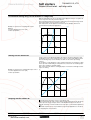
Conventional starting
of three-phase asynchronous motors
'LUHFWVWDUWLQJ
I/In
# Starting current: 4 to 8 times the nominal current
C/Cn
6
3
5
2,5
4
2
3
1,5
2
1
1
0,5
# Starting torque: 0.5 to 1.5 times the nominal torque
#
5
5
5
5
5
Cr
0
0
0,25 0,5 0,75
N/Ns
1
0
6WDUWLQJFXUUHQW
0
0,25 0,5 0,75
Characteristics:
Motor with 3 terminals, low and medium power
On-load starting
High current peak and voltage drop
Simple device
Sudden starting for the mechanism
# No parameter adjustment
N/Ns
1
6WDUWLQJWRUTXH
6WDUGHOWDVWDUWLQJ
# Starting current: 1.8 to 2.6 times the nominal current
C/Cn
3
I/In
6
# Starting torque: 0.5 times the nominal torque
5
2,5
4
2
3
1,5
2
1
1
0,5
0
N/Ns
0
0,25 0,5
0,75
0
1
6WDUWLQJFXUUHQW
#
5
5
5
5
5
Cr
0
0,25
0,5 0,75
1
Characteristics:
Motor with 6 terminals
No-load or low resistive torque starting
High current peaks and torque when changing to "star-delta" mode
A device requiring maintenance
Subject to mechanical stress when starting
# No parameter adjustment
N/Ns
6WDUWLQJWRUTXH
5KHRVWDWLFVWDWRUVWDUWLQJ
# Starting current: 4.5 times the nominal current
C/Cn
3
I/In
6
# Starting torque: 0.5 to 0.75 times the nominal torque
5
2,5
4
2
3
1,5
2
1
1
0,5
0
0
0,25 0,5
0,75
1
N/Ns
0
6WDUWLQJFXUUHQW
#
5
5
5
5
5
Cr
0
0,25
0,5 0,75
1
Characteristics:
Motor with 3 terminals, high power
Starting with increasing resistive torque
High current peak
A large, bulky device requiring maintenance
Subject to mechanical stress when starting
# No parameter adjustment
N/Ns
6WDUWLQJWRUTXH
$XWRWUDQVIRUPHUVWDUWLQJ
6
# Starting current: 1.7 to 4 times the nominal current
C/Cn
I/In
3
# Starting torque: 0.4 to 0.85 times the nominal torque
5
2,5
4
2
3
1,5
2
1
1
0,5
0
0
0,25 0,5 0,75
6WDUWLQJFXUUHQW
48
1
N/Ns
#
5
5
5
5
Cr
0
0
0,25 0,5
0,75
1
Characteristics:
Motor with 3 terminals, high power
Large voltage drop and current peak when connected at full voltage
A complex, bulky device requiring maintenance
Subject to mechanical stress when starting
# No parameter adjustment
N/Ns
6WDUWLQJWRUTXH
www.thianovation.com
Schneider Electric
&XUYHVFRQWLQXHG
6RIWVWDUWHUV
TiNAMiCS CO.,LTD.
Progressive starting
of three-phase asynchronous motors
&RQYHQWLRQDOHOHFWURQLFVWDUWLQJZLWKYDULDEOHYROWDJHDQGFXUUHQWOLPLWLQJ
# A controller with 6 thyristors connected head to tail in each line phase is used to power the
three-phase asynchronous motor by gradually increasing the voltage on start-up.
5 Depending on the firing time and angle of the thyristors, it can be used to supply a voltage
M
which will gradually increase at a fixed frequency.
3
5 The gradual increase in the output voltage can either be controlled by the acceleration ramp,
or by the value of the limiting current, or linked to both parameters.
6FKHPDWLFGLDJUDP
α
α
)LULQJDQJOH
# Figure 1 shows the behaviour of the torque in relation to the starting current.
Id
Limiting the starting current Is to a preset value Is1 will reduce the starting torque Ts1 to a value
which is almost equal to the ratio of the square of currents Is and Is1.
([DPSOH
On a motor with the following characteristics: Ts = 2 Tn for Is = 6In, current limiting at Is1= 3 In
or 0.5 Is results in a starting torque: Ts1 = Ts x (0.5)2 = 2 Tn x 0.25 = 0.5 Tn.
Id1
Cd
Cr
Cd1
0
N/Ns
0
0,25
0,5
0,75
1
)LJXUH
# Figure 2 shows the torque/speed characteristic of a squirrel cage motor in relation to the
C
supply voltage.
The torque varies like the square of the voltage at a fixed frequency. The gradual increase in the
voltage prevents the instantaneous current peak on power-up.
U
0,85 U
Cr
0,6 U
0
N/Ns
0
0,25
0,5
0,75
1
)LJXUH
$GYDQWDJHVRIVWDUWLQJZLWKWKH$OWLVWDUW
# Conventional electronic starting
To rectify problems caused by:
- mechanical stress when starting
- hydraulic transients during acceleration and deceleration in pump applications
Conventional electronic starting requires the use of several current limits or the switching of
several voltage ramps.
The settings become complicated and must be modified every time the load changes.
# Starting with the Altistart 48
The Altistart 48 torque control enables starting without mechanical stress and the smooth control
of hydraulic transients with a single acceleration ramp.
The settings are simple and effective, whatever the load.
Schneider Electric
www.thianovation.com
49