1
7J
,'0²&2167$17&855(175(*8/$725
8VHU0DQXDO
2 / 39
,'0±8VHU0DQXDO
,'0²&2167$17&855(175(*8/$725
8VHU0DQXDO
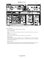
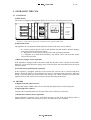
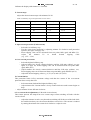
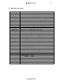
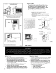
9HUVLRQVFRYHUHGE\WKLVPDQXDO
IDM 7000- /1-30 KVA
1
2-6
F
E
S
X
Constant current regulator 1-30 kVA
Direction changer
Circuit selector
FAA-monitor IDM 7000-03
Earth fault monitor
Surge arresters
Extra monitor
Revision index
Revision:
Author
Date:
Description
T-7000-2
JK
30.05.1994
T-7000-2d
JK
01.08.1996
Cards 01b, 03b, 04c
T-7000-2e
JK/JN
24.08.1998
Card 03d
T-7000-2f
JK/JN
29.10.1998
Card 01c
T-7000-2g
JR
28.05.2001
New format
:$51,1*
7KHHTXLSPHQWFRQWDLQVKLJKYROWDJHFLUFXLWVDQGFRPSRQHQWVZKLFKPD\FDXVHDOLIH
KD]DUG
The doors and covers should be only opened by qualified personnel.
7KLVPDQXDOLVSURSHUW\RI,GPDQ±3KLOLSVOLJKWLQJ
&RS\LQJLQDQ\IRUPRUWUDQVPLWWLQJWRDWKLUGSDUW\ZLWKRXWRZQHUV
ZULWWHQFRQVHQWYLRODWHVFRS\ULJKWODZVDQGLVIRUELGGHQ
,'0$12<
.LVlOOLQWLH
),19DQWDD
)LQODQG
7HOHSKRQH
7HOHID[ HPDLO
IRUHQDPHIDPLO\QDPH#SKLOLSVFRP
,'0$13KLOLSVOLJKWLQJ
,'0±8VHU0DQXDO
Contents:
1.
2.
4.
5.
1.1
AIRPORT LIGHTING SYSTEMS................................................................................................................... 4
1.2
CIRCUIT DESIGN ......................................................................................................................................... 5
1.3
SERIES CIRCUIT.......................................................................................................................................... 5
1.4
GROUNDING OF A SERIES CIRCUIT.......................................................................................................... 6
1.5
SELECTING THE REGULATOR SIZE .......................................................................................................... 6
1.6
PARALLEL CIRCUIT ..................................................................................................................................... 8
CCR OPERATING PRINCIPLE.............................................................................................................................. 9
2.1
REGULATOR CIRCUIT BASIC THEORY...................................................................................................... 9
2.2
CCRS FUNCTION BLOCKS AND THEIR OPERATIONS ............................................................................. 9
High voltage unit ................................................................................................................................. 11
2.2.3
Electronic unit ..................................................................................................................................... 12
OPERATING THE CCR ....................................................................................................................................... 14
3.1
CONTROLS ................................................................................................................................................ 14
3.2
METERS ..................................................................................................................................................... 14
INSTALLATION.................................................................................................................................................... 15
COMMISSIONING ............................................................................................................................................... 18
5.1
SERIES CIRCUIT........................................................................................................................................ 18
5.2
LOGIC UNIT IDM 7000-01........................................................................................................................... 18
5.3
REGULATOR UNIT IDM 7000-02................................................................................................................ 20
5.4
FAA-MONITOR UNIT IDM 7000-03d (option) .............................................................................................. 22
5.4.2
7.
Power unit........................................................................................................................................... 10
2.2.2
5.4.1
6.
page
GENERAL.............................................................................................................................................................. 4
2.2.1
3.
3 / 39
Lamp fault settings ............................................................................................................................. 22
VA-drop settings ................................................................................................................................. 24
5.5
EXTRA MONITOR UNIT IDM 7000-09a (option) ........................................................................................ 25
5.6
EARTH FAULT MONITOR IDM 7000-05 (option) ........................................................................................ 26
5.7
MAIN MOTHER BOARD IDM 7000-04 ........................................................................................................ 27
5.8
CIRCUIT SELECTOR MOTHER BOARD IDM 7000-08............................................................................... 28
5.9
MAIN TRANSFORMER ............................................................................................................................... 29
5.10
COMMISSIONING CHECK LIST ................................................................................................................. 30
TROUBLE SHOOTING ........................................................................................................................................ 31
6.1
SUPPLY VOLTAGE CHECK ....................................................................................................................... 31
6.2
CCR WILL NOT START AT ALL ................................................................................................................. 31
6.3
CCR GIVES AN OPEN CIRCUIT ALARM ................................................................................................... 32
6.4
CCR GIVES AN OVER CURRENT ALARM ................................................................................................ 32
6.5
CCR IS ON BUT CURRENT SEEMS TO BE UNSTABLE ........................................................................... 32
6.6
MAIN FUSE IS BLOWN .............................................................................................................................. 32
MAINTENANCE ................................................................................................................................................... 33
7.1
PREVENTIVE MAINTENANCE ................................................................................................................... 33
7.1.1
CAT II, CAT III preventive maintenance requirements ........................................................................ 33
7.1.2
Preventive maintenance recommen of the stop-bar lighting ...................................................................
system (RVR<350 m) ......................................................................................................................... 33
7.1.3
Preventive maintenance recommendations of the taxi way lighting system ...........................................
(RVR<350 m)...................................................................................................................................... 33
7.1.4
CAT I preventive maintenance recommendations............................................................................... 34
7.1.5
Preventive maintenance recommendations of RVR <550 m take off runway ..................................... 34
7.1.6
Preventive maintenance recommendations of RVR>550 m take off runway ...................................... 34
7.1.7
Fulfillment of ICAO:s preventive maintenance objectives.................................................................. .. 34
7.1.8
Centralised system with IDM 7000-03 FAA monitor ........................................................................... 34
7.1.9
Distributed monitoring systems........................................................................................................... 35
7.2
MAINTENANCE OF THE CCR.................................................................................................................... 35
7.3
IDM 7000 CARD VERSIONS....................................................................................................................... 36
7.4
CUSTOMER FEEDBACK ,RECLAMATIONS AND AFTERSALES SERVICES........................................... 36
8.
TECHNICAL DATA .............................................................................................................................................. 37
9.
APPENDIX 1 : EARLIER CARD VERSIONS........................................................................................................ 38
,'0$13KLOLSVOLJKWLQJ
4 / 39
,'0±8VHU0DQXDO
*(1(5$/
$,53257/,*+7,1*6<67(06
Airport lighting systems are used as visual aids to indicate a pilot the right approach path and
the runway with its sections. After landing, taxiing is guided by the lighting system. The main
principle is to indicate the edges, centrelines and some other important lines of the runway with
numerous relatively low powered and precisely aligned fittings instead of trying to illuminate
the whole surface of the runway.
The lighting systems are normally based on ,&$2¶s (International Civil Aviation Organisation)
recommendations of which $QQH[deals with the lighting systems. According the Annex 14
the lighting systems are classified into following categories:
D1RQSUHFLVLRQDSSURDFKUXQZD\
Runway which is equipped with lighting system and navigation system which at least gives
directional guidance for direct approach.
E3UHFLVLRQDSSURDFKUXQZD\&$7,
Runway that is equipped with lighting system and ILS system and which facilitates operations
down to 60m decision height and 800m RVR (Runway Visual Range).
F3UHFLVLRQDSSURDFKUXQZD\&$7,,
Runway that is equipped with lighting system and ILS system and which facilitates operations
down to 30m decision height and 400m RVR (Runway Visual Range).
G3UHFLVLRQDSSURDFKUXQZD\&$7,,,
Runway that is equipped with lighting system and ILS for approach and runway operations and
which is arranged to following sub-categories:
$- Runway for operations down to 200m RVR and where decision height is not anymore
specified. The lighting system is needed on the final phase of landing.
%- Runway for operations down to 50m RVR and where decision height is not anymore
specified. The lighting system is only needed for taxiing operations.
&- Runway for operations where visual guidance is not anymore needed.
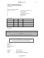
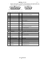
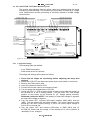
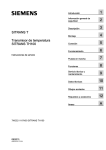
7DEOH6XEV\VWHPVRIDOLJKWLQJV\VWHPVHHILJXUH
1XPEHU
/LJKWLQJV\VWHP
$EEUHYLDWLRQ
1
Approach lighting system
APCH
2
Threshold lighting system
THR
3
Precision approach path indicator system
PAPI
4
Runway edge and end lighting system
RWYE
5
Runway centreline lighting system
RCL
6
Touchdown zone lighting system
TDZ
7
Taxiway edge lighting system
TWYE
8
Taxiway central lighting system
TCL
9
Stop-bar lighting system
SB
,'0$13KLOLSVOLJKWLQJ
,'0±8VHU0DQXDO
5 / 39
)LJXUH$OLJKWLQJV\VWHPOD\RXWZLWKVXEV\VWHPV
&,5&8,7'(6,*1
According ICAO’s Annex 14 and $HURGURPH GHVLJQ PDQXDO SDUW the circuits should be
arranged for a SUHFLVLRQDSSURDFKUXQZD\ (CAT I...III) as follows.
7DEOH&LUFXLWSDUWDJH
Approach lighting system
At least 2 interleaved circuits
Threshold lighting system
At least 2 interleaved circuits, can be also
integrated into APCH s
PAPI
At least 2 interleaved circuits, interleaving to be
done in each unit
Runway lighting system
At least 2 interleaved circuits
Taxiway edge lighting system
Single circuit may be used
Taxiway
system
At least two interleaved circuit for CAT III-areas.
Other areas single circuits may be used. Circuits
to be in sections to enable selective switching.
centreline
lighting
Stop-bar lighting system SB
2 interleaved individual circuits for each SB
Interleaving should be done in such a way that the light patterns and colour coding of the subsystems should not change if one of the circuits should fail. The light fittings are fed by a
supplying device that normally provides 5 brilliancy steps and can be controlled with remote-or
local control. The ratings of the light fittings usually vary from 45 to 200W and the circuits up
to 30 kW. Two kinds of circuits are normally used: series and parallel circuit.
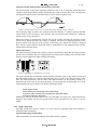
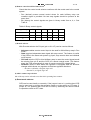
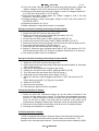
6(5,(6&,5&8,7
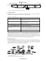
In series circuit the light fittings are connected in series with 1/1 isolation transformers and 1core airport lighting cable. The circuit is fed with constant current regulator (CCR) which
adjusts constant current for the light fittings by regulating its output voltage. Connections are
made with primary and secondary connectors. See Figure 2.
)LJXUH6HULHVFLUFXLW
Series circuit gives following main advantages:
,'0$13KLOLSVOLJKWLQJ
,'0±8VHU0DQXDO
6 / 39
Equal brilliancy for all light fittings in the circuit (equal current)
Small power loss and cable size (Relatively low current 6.6A)
Wide range of intensity control (0,3 ...100%)
1-point ground faults do not effect the operation of the system and 2-point faults only
partially.
On the other hand high output voltage (up to 5kV) requires care to be taken when working with
the circuits.
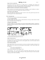
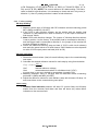
*5281',1*2)$6(5,(6&,5&8,7
According the Aerodrome design manual part 5 all the equipment in the electrical stations
should be grounded. A ground wire should also be installed with the series circuit cables into
which all supports of elevated lights and secondary of the isolation transformers should be
connected. The circuit is normally isolated from the ground (CCR main transformer) but in case
of an earth fault and simultaneous high voltage break through proper grounding will protect the
personnel from electrical shocks. See figure 3 for details.
)LJXUH(IIHFWVRIJURXQGLQJRIDVHULHVFLUFXLW
Up (potential difference) between the earth fault point and the break through point in
connection with the earth fault resistance Re , earth capacitance Xc and human resistance Rm
defines the current that would go through a human being touching the break through point.
Currents from 30mA are considered to be fatal. Proper grounding would by-pass the Rm and
therefore give protection against the ground fault. However, there are arguments for and against
the grounding i.e. local conditions and national regulations should be considered when
designing the grounding system.
6(/(&7,1*7+(5(*8/$7256,=(
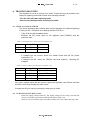
When selecting a regulator for a lamp load, following things should be considered:
The regulator rating given in kVA is the output power of the CCR. When supplying a
load with unity power factor, the rating can be considered in kW.
The input power is approx. 1,1 times the output power.
In calculation lamp load, auxiliary load, primary- and secondary cable loads, isolation
transformer characteristic factors and possible under voltage reserve should be taken
in account.
,'0$13KLOLSVOLJKWLQJ
7 / 39
,'0±8VHU0DQXDO
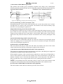
)LJXUH)RUPXODIRUVHOHFWLQJD&&5
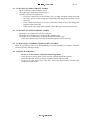
The isolation transformers can normally tolerate 10%-20% overload (PL+Paux+Psc). If further
overloaded the output current decreases. See following Table 3 for selecting correct secondary
cable cross-sections for different transformers and cable lengths.
7DEOH0D[LPXPFDEOHOHQJWKVIRUGLIIHUHQWLVRODWLRQWUDQVIRUPHUVRYHUORDG
7UDIRVL]H :
PP&XPD[LPXPOHQJWKP
(R=0.0165 ohm/m, P=0.72 W/m)
PP
&X
OHQJWKP
PD[LPXP
(R=0.0103 ohm/m, P=0.44 W/m)
45
12
20
65
18
29
100
28
45
150
42
67
200
56
90
A CCR may be slightly oversized for lamp faults. When a lamp has failed (filament burnt open)
transformers secondary side will open and the transformer be saturated which will increase the
voltage over it (typically 40-100V/ 200W transformer). In case of many lamp faults the voltage
can rise so high that the regulator is not capable to maintain the output current. Normally
regulators can tolerate up to 30-50% lamp failures depending of the saturation voltage of the
isolation transformers. This can be prevented by oversizing the CCR or using transformers with
lower
saturation
voltage
and
by
efficient
lamp
failure
monitoring.
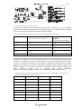
Primary cable size and its protective fuse can be estimated from the following Table 4
7DEOH(VWLPDWLQJSULPDU\FDEOHDQGIXVHVL]HVXSSO\YROWDJH91DWLRQDOUHJXODWLRQVDQG
LQVWDOODWLRQPHWKRGVPXVWEHWDNHQLQDFFRXQW
6N9$
,PD[$
&DEOH&X
)XVH
3
15
2,5mm2
16A
5
24
4mm2
25A
7,5
36
10mm2
50A
10
48
10mm2
63A
12
58
16mm2
63A
17
82
25mm2
100A
20
96
25mm2
100A
25
120
35mm2
125A
,'0$13KLOLSVOLJKWLQJ
,'0±8VHU0DQXDO
8 / 39
3$5$//(/&,5&8,7
In parallel circuit the light fittings are connected parallel to a supplying device. The fittings do
not have equal brilliancy because of the voltage losses of the circuit. Also power losses are high
due relatively high current in the circuit. Parallel circuits are mostly used with taxiway/apron
applications that are located close to electrical stations.
,'0$13KLOLSVOLJKWLQJ
,'0±8VHU0DQXDO
9 / 39
&&523(5$7,1*35,1&,3/(
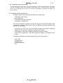
5(*8/$725&,5&8,7%$6,&7+(25<
Basically a regulator circuit consists of three different elements:
The regulator element
The control element
The feedback element
The task of a regulator is to keep a desired output value determined by a set value. The
regulator checks if there is a difference between these two values and adjusts the output
accordingly through the control element. In case of a CCR the regulator is located in the
regulator card. The control element is a thyristor pair that chops the sinusoidal input voltage
and the feedback element consists of a current transformer and a RMS-computer in the
regulator card.
)LJXUH2SHUDWLQJSULQFLSOHRIDUHJXODWRU
In a CCR the output voltage defines the output current which is kept constant despite
changes of output load or supply voltage.
&&56)81&7,21%/2&.6$1'7+(,523(5$7,216
Main functions of a CCR are:
to define and maintain desired current values (brightness levels)
to isolate the AFL-circuit from the ground
to monitor the status of the circuit
to compensate changes of the load and supply voltage
The CCR consists of three different function blocks:
the power unit
the high voltage unit
the electronic unit
,'0$13KLOLSVOLJKWLQJ
,'0±8VHU0DQXDO
10 / 39
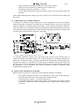
)LJXUH%ORFNGLDJUDPRID,'0FRQVWDQWFXUUHQWUHJXODWRU
3RZHUXQLW
The power unit consists of following main components.
0DLQVZLWFKDQGIXVH
The main switch connects the supply and the main fuse protects the power unit from over
current.
6XUJHDUUHVWHURSWLRQDO6
Optional surge arresters protects the power unit from over voltage surges.
0DLQFRQWDFWRU
The main contactor switches the regulator on or off. Switching is made in such a way that the
contacts of the contactor are currentless in order to avoid transients and to provide maximum
operating life for the contacts.
3DVVLYH/&ILOWHU
The passive LC-filter protects the power unit from high frequency disturbances. The choke of
the filter also limits fast current changes in the circuit in case of sudden load changes.
,'0$13KLOLSVOLJKWLQJ
,'0±8VHU0DQXDO
11 / 39
7K\ULVWRUPRGXOHZLWK5&ILOWHUDQGWK\ULVWRUFRQWUROOHU
The thyristor pair is the actual regulating element of the CCR. It chops the sinusoidal mains
voltage to form desired RMS-voltages that define the output current of the CCR. The thyristors
are triggered by the thyristor controller which is driven by the regulator card.
)LJXUH9ROWDJHDQGFXUUHQWFXUYHVDVDIXQFWLRQRIWLPH6XSSO\YROWDJHGDVKOLQH
The triggering angle D defines the moment when the thyristor is ignited (opened) and the
current starts to flow through it. The thyristor will close itself at the moment (t1) when the
current ceases to flow through it.
When the voltage is chopped the current will lag the voltage and thus the inductive power
factor will be smaller the more the voltage is chopped. The need for chopping depends on the
desired current level and the CCRs capacity /load rating ratio. When the voltage is chopped
there will be some harmonic distortion which is proportional to the triggering angle and the
current drawn from the mains.
0DLQWUDQVIRUPHU
The main transformer defines the capacity of the CCR and also isolates the afl-circuit from the
ground. The transformer has got 3 tapping both on primary and secondary sides with which the
capacity can be adjusted to match with the load rating.
)LJXUH$GMXVWLQJRIDWUDQVIRUPHUWRDFLUFXLW
The input current and its harmonic content depend practically only on the output current and
the transforming ratio n2/n1. On the other hand the losses of the CCR which primarily come
from the main transformer and the choke and depend mainly on the primary current (e.g.
depend on the CCR capacity not the load rating). In conclusion this all means that if a CCR is
well matched with a given load it will lead to following benefits:
better power factor
better efficiency compared to the load rating
minimum input current level compared to the load rating
minimum harmonic distortion
Matching is done by choosing correct CCR size and futher by using CCRs main transformers
tappings. The benefits will be even greater when UPS or generator sets are used as a power
supply.
+LJKYROWDJHXQLW
The high voltage unit which in CCRs over 12 kVa forms a separated cabinet and consists of
following main components:
&XUUHQWDQGYROWDJHWUDQVIRUPHUV
These transformers provide the feedback information for the regulator
,'0$13KLOLSVOLJKWLQJ
12 / 39
,'0±8VHU0DQXDO
6XUJHDUUHVWHUVRSWLRQDO6
The arresters protect the CCR from over voltage surges (e.g. lightning). The arresters will
automatically recover after they have operated. When the arrester has failed it will make an
earth fault and can be therefore identified with the earth fault monitor.
'LUHFWLRQVZLWFKRUFLUFXLWVHOHFWRUFRQWDFWRUV2SWLRQDO
These contactors will switch the selected circuits. Switching is made currentless in order to
avoid transients and to provide maximum life span for the contacts.
(DUWKIDXOWPRGXOH,'009
This card connects the earth fault monitor with the circuit and ground and provides the
measuring signal for the earth fault monitor.
(OHFWURQLFXQLW
The electronic unit consists of following main components.
D/RJLFXQLW,'0
The card includes the remote and local control functions, reset logic, main contactor control
logic and optional direction changer logic.
E5HJXODWRU,'0
The card includes the actual regulator of the CCR including TRMS-computers, synchroniser,
modulator, reference generators, regulator amplifiers, protection electronics and the power for
the electronics.
)LJXUH2SHUDWLQJSULQFLSOHRIWKHSURWHFWLRQV
The card includes following protective devices:
2SHQFLUFXLWSURWHFWLRQ
If output current does not reach the set level or decreases under it the regulator will trip off in
0,5s and the red "Open circuit" led will lit on the regulator card. To reset it turn the CCR off
either by local or remote control.
2YHUFXUUHQWSURWHFWLRQ
If the output current in the circuit increases over the set values the regulator will trip off as
follows. Red "Over current" led on the regulator card will light. To reset it turn off the CCR.
See figure 9.
level 1 (Oc1), slow protection 5s
level 2 (Oc2), fast protection 1s
Under voltage monitoring (in the regulator card)
If the electronic (+ and - power) fuses operate or the mains voltage decreases 15% or more
under the nominal value the regulator will trip off. This protects the power circuit from under
voltage eg. main contactor unstability.
,'0$13KLOLSVOLJKWLQJ
13 / 39
,'0±8VHU0DQXDO
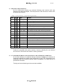
F)$$PRQLWRU,'0RSWLRQDO)
This optional card includes power calculation computers and voltage curve measurement,
reference generators and monitoring logic for lamp fault, current fault and VA-drop monitoring.
VA-DROP MONITORING
W
VA
ALARM A
CURRENT FAULT MONITORING (CF)
i
OVER CURRENT
SET LEVEL A
ALARM
ALLOWABLE RANGE
ACTUAL VALUE
ACTUAL VALUE
30s
30s
t
t
t
CF
OPEN CIRCUIT
t
)LJXUH2SHUDWLQJSULQFLSOHRIWKHPRQLWRULQJFLUFXLWV
9$GURSPRQLWRULQJLQWKH)$$PRQLWRUFDUG
If the apparent power (S/VA) of the circuit decreases 10% or more the red led "10% VA-drop"
will light after 30 seconds on the FAA-monitor. The function works with all brilliancy steps
and can be reset by turning the regulator off.
/DPSIDXOWPRQLWRULQJLQWKH)$$PRQLWRUFDUG
For lamp fault two fault levels can be chosen. If the actual lamp fault voltage increases over the
pre-set values first red "Lamp fault a" led will lit on the monitor card. If the actual lamp fault
voltage increases further the red "Lamp fault b" led will light. When using a circuit selector,
alarm works only when all circuits are chosen. The function can be reset by turning the CCR
off.
&XUUHQWIDXOWPRQLWRULQJLQWKH)$$PRQLWRUFDUG
If the current in the circuit differs from the set value but is between over-and under current
values (no tripping), the red "Current fault" led on the FAA-monitor will light. The function
can be reset by turning the regulator off .
G0DLQPRWKHUERDUG,'0
This card connects the plug in cards with each other and contains also most of the remote
control indication relays and the rectified power supply for the electronics.
H(DUWKIDXOWPRQLWRU,'0DQGPRWKHUERDUG2SWLRQDO(
This optional card includes measuring and monitoring electronics, individual power supply and
is galvanically isolated from the other electronic cards.
If the isolation resistance of the circuit decreases under the set value first red "Earth fault a"
will lit. If the isolation resistance decreases further, also red led "Earth fault b" will light. The
isolation resistance can be read from the M-ohm meter on the front panel. The function is
always on when the CCR is energised and can be reset by turning off the main switch S1.
127( Current limited 100 VDC measuring voltage is always on the circuit, when the CCR
is energised. Switch off the main switch when doing maintenance works with the circuit!
I&LUFXLWVHOHFWRU,'0DQGPRWKHUERDUG2SWLRQDO
This card includes remote and local control logic for the circuit selector
,'0$13KLOLSVOLJKWLQJ
14 / 39
,'0±8VHU0DQXDO
23(5$7,1*7+(&&5
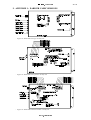
&21752/6
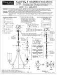
D0DLQVZLWFK
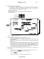
The switch S1 energises the regulator and the green "Power" led will lit on logic unit.
Logic unit
Regulator
Earth fault
monitor
FAA-monitor
Circuit
selector
Circuit 1
0
IDM 7000
R
Circuit 2
Ampere meter
Total hours meter
Earth fault a
Circuit 3
Earth fault b
Earth fault meter
Circuit 4
Circuit 5
Constant
Current
Regulator
Circuit 6
Volt meter
1
2
100% hours meter
)LJXUH/RFDOFRQWUROSDQHORIWKHFRQVWDQWFXUUHQWUHJXODWRU,'0
E2SHUDWLRQVZLWFK
The regulator can be operated with the operation switch on the logic unit as follows.
R = Remote control operates only in this position. Switch disables direction changer
and circuit selector from local controls.
0 = Regulator is off. Position resets protection and monitoring functions.
% = Regulator is on with desired brilliancy step which can be seen from the yellow
LED on the logic unit.
F'LUHFWLRQFKDQJHUVZLWFKRSWLRQDO
If the regulator is equipped with a direction switch, the direction can be selected in local mode.
Direction 1 is the main direction (bigger load). LED will show the selected direction in remote
and local modes
G&LUFXLWVHOHFWRUSXVKEXWWRQVRSWLRQDO
If the regulator is equipped with the circuit selector the circuits can be selected with these
buttons. When the button is pressed down the circuit is selected and the button lit. When the
button is pressed again, the circuit and the led will turn off. When switching off circuits, the
regulator will provide a special low current to protect the lamps from surges.
0(7(56
D'LJLWDO9ROWDQGDPSHUHPHWHUV
Current and voltage TRMS-values can be read from the digital meters on the front panel.
E2SHUDWLQJKRXUFRXQWHUV
Counters show operating hours for total and 100% (max. brilliancy level) hours.
F,QVXODWLRQUHVLVWDQFHPHWHU2SWLRQDO
Actual insulation resistance can be read from the meter on the front panel. Range from 10
Mohm down to 10 kohm. The function is always on when the CCR is energised.
,'0$13KLOLSVOLJKWLQJ
,'0±8VHU0DQXDO
15 / 39
,167$//$7,21
IDM 7000 constant current regulators are supplied in 3 different modular cabinets.
7DEOH,'0FDELQHWVZLGWKPPGHSWKPPIRUDOOXQLWV
7\SH
KHLJKW
&&5VL]HV
1U
450
3 kVA and smaller
2U
900
4-12kVA
3U
1350
15kVA and larger
All cabinets are free standing ands can be installed on a cable pit on the floor or by using IDM
7000-IS installation rack system which allows stacking and therefore provides a space saving
assembly. The bottom plate of the 2U and 3U cabinets is lifted 10 cm from the floor plane to
allow trucks and lifting devices to be used.
)LJXUH0RXQWLQJH[DPSOHRI,'08FDELQHW
Rubber cable glands are provided for all cable entries.
Supply cable is connected directly to the main switch S1 terminals and main
grounding on the bottom plate.
Airfield lighting cables are connected to their terminals according the wiring diagram
supplied with the regulator. A character pair defines a circuit i.e. A, a. If the CCR is
with direction change, connect the main (bigger) load to direction 1 (A, a) and smaller
load to direction 2 (B, b). This is related with the FAA-monitor load balancing
functions. Ground points are located on the mounting plate. In 3U cabinet the output
terminals are located in the lower high-voltage compartment.
,'0$13KLOLSVOLJKWLQJ
,'0±8VHU0DQXDO
16 / 39
Remote control cables are connected with D-connectors to the mother boards. See
Figure 13 and Table 6 and Table 7 for connection details. The cables can be fixed
with cable suspenders installed in a rail on the mounting plate.
)LJXUH'FRQQHFWRUVRIWKHUHPRWHFRQWURO
7DEOH;'VLJQDOVRIWKHUHPRWHFRQWURO
3LQ
1
6LJQDO
Control step 1 (A)
2
3
4
5
6
Control step 2 (B)
Control step 3 (C)
Control step 4
Control step 5
Control step 6 (D)
7
8
Gnd (0 V, -), control
Common ind 1
9
On-indication
10
Common fault indication
11
Local indication
12
13
14
15
Lamp fault indication a
Lamp fault indication b
Earth fault indication a
Off indication
16
17
Earth fault indication b
Remote-indication
18
Aux.
On-indication
(direct)
VA-drop indication
Current fault indication
Open circuit indication
Over current indication
Common ind 2
Direction indication /
direction 1
Direction indication /
direction 2
19
20
21
22
23
24
25
*URXS 5HPDUN
R
Normal
or
binary
coded
mode,steady
signal,24/48/60V DC selectable
R
Normal or binary coded mode
R
Normal or binary coded mode
R
Normal mode
R
Normal mode
R
Normal or binary coded mode, D-mode: start,
failsafe, direction
R
Common gnd for controls
PI,FI
Indication group 1 common. Max 60V DC potential
free
PI
NO= Contact closed when the CCR is on, power off
state=0
FI
NC, Includes :mains failure, over/undercurrent,
10%VA-drop and current fault
FI
NO, Contact on when the operation switch is out of
“R” (remote) position
FI
NO = Contact closed when the fault exists
FI
NO
FI
NO
PI
NC =Contact closed when CCR is off .Power off
state=1.
FI
NO
FI
NC, Contact is on when the operation switch is in
“R” (remote) position
FI
NO Contact is on when the CCR is on
FI
FI
FI
FI
PI,FI
PI
PI
NO optional
NO optional
NO optional
NO optional
Indication group 2 common
NO, Option. Indication when the regulator and the
selected direction is on
NC, Option. Indication when the regulator and the
selected direction is on
,'0$13KLOLSVOLJKWLQJ
17 / 39
,'0±8VHU0DQXDO
7DEOH&RQWUROVLJQDOVRI;FRQQHFWRU'
3LQ
6LJQDO
1
2
3
4
5
6
7
Control, circuit 1
Control, circuit 2
Control, circuit 3
Control, circuit 4
Control, circuit 5
Control, circuit 6
Indication, circuit 1
8
9
10
11
12
13
14
15
Indication, circuit 2
Indication, circuit 3
Indication, circuit 4
Indication, circuit 5
Indication, circuit 6
Indication, circuit 1
Gnd (0V,-)
Spare
*URXS
5HPDUN
1=on,0=off,steady signal 24/48/60 V DC selectable
PI
PI
PI
PI
PI
PI
PI
NO= Contact closed when circuit is on, power off
state =0
NO
NO
NO
NO
NO
NC
Control and indication (ind. mode) common
If programmable remote control system is used, following indications can be programmed to
the system and be inferred from the control status, on, local and common fault signals:
D6XSSO\YROWDJHIDXOWLQGLFDWLRQ0DLQVIDLOXUH
CCR is not on and not controlled on and not in local mode and common fault exists
E9$GURSFXUUHQWIDXOWLQGLFDWLRQ9DFIDOO
CCR is on and Common fault exists
F8QGHUFXUUHQW2YHUFXUUHQWLQGLFDWLRQ2F8FDO
CCR is off and common fault exists and (CCR is controlled on or is in local control)
G&XUUHQWVWHSLQGLFDWLRQ
Step is controlled on and on indication
Following indications are available as options.
exists
and
common
Current step information, 6-steps, NO-contacts, extra terminal block
Normal delivery includes following components and documents:
Constant current regulator IDM 7000
IDM EB extension card 1pcs/CCR
Accessory package (fuses, screws, cable connectors etc.)
Technical document T-7000-01d for IDM 7000
Circuit diagrams: main circuit diagram, remote control connection
Spare parts list
Factory test report
Commissioning test report (blank)
,'0$13KLOLSVOLJKWLQJ
fault
is
off
18 / 39
,'0±8VHU0DQXDO
&200,66,21,1*
First test run should be done with dummy load because the CCR can be damaged during storage
or transportation.
Connect an TRMS A-meter (AC-range) in series with the test load and connect a DCvoltmeter to the measuring points MP1 (0V) and Iact (current actual value) on
regulator card.
Run CCR with all brilliancy steps to be sure that they are working properly and check
that readings of the meters are same. If the output on any step is more than 6,6A
adjust it lower with trimmers P1-P6.
After checking that the CCR and series circuit is OK, commissioning can be done with the
actual circuit. Fill in the measured values to the commissioning test report supplied with the
regulator.
6(5,(6&,5&8,7
Before running the actual circuit with CCR, following values of the circuit should be measured
and recorded.
Calculated circuit load.
Insulation resistance to the ground ( >10 Mohm is good, down to 100 kohm can be tolerated).
Check that the circuit is disconnected from the CCR when testing. Use at least 500V DC tester.
Discharge the circuit before touching the cable conductors.
Continuity of the circuit ( typical values less than 100 ohm). Multimeter can be used.
/2*,&81,7,'0
Failsafe selectors
Failsafe
A
D-Mode
Power led
1. brilliancy step led
2. brilliancy step led
PKR5
BinDec
N
FS
Operation switch
Remote control voltage selector
steps 1-5 or A,B,C
N
PKR7
FS
Failsafe
B
Control mode
Binary Decimal
N
PKR9
DEC/BIN
FS
SELECTOR
Failsafe
PKR2 PKR3
C
Remote control
selector
PKR1
24
48
60
D mode
selector
Bin
Bin
Bin
Bin
Bin Dec Dec
Bin Bin Dec
Bin Bin Dec
Bin Bin Dec
2
3
4
5
6
24
48
60
D mode selector
5. brilliancy step led
c1
8
12
14
PKR6
16
PKR10
Remote control voltage selector
step 6 or D
3. brilliancy step led
4. brilliancy step led
4
6
Decimal/binary
10
control mode selector
PKR10 PKR2 PKR3 PKR2 PKR3 1
6 th step
2,4
Start
1,6
Failsafe mode 2,3
Direction
2,5
2
PKR4
h 100%counter
step selector
L
L+R
18
20
22
24
Connector coding
a4
26
28
6. brilliancy step led
PKR8
Direction switch
Direction leds
Reset mode selector
S6
30
S5
32
h 100%
counter
IDM 7000-01 / c
01.06.1998
)LJXUH/RJLFFDUG,'0F
D5HPRWHFRQWUROYROWDJHVHOHFWRU
24V, 48V and 60V DC can be selected. Check that the remote control voltage
selector settings conform with the voltage used in the system. Jumpers are used
for the selections.
,'0$13KLOLSVOLJKWLQJ
19 / 39
,'0±8VHU0DQXDO
E5HPRWHFRQWUROPRGH'HFELQVHOHFWRU
Check that the control mode selector conforms with the mode used in the control
system.
Dec (decimal) means normal control where for each brilliancy step one
constant signal is provided. No two step signals should be present at the
same time.
Bin (binary) the control signals are given in binary coded from a, b, c. See
Table 8.
Table 8. Binary control signals
VLJQDOVWHS
3
A
x
B
C
3
3
3
x
x
3
3
x
x
x
x
x
x
F'PRGHVHOHFWRU
With D-mode selector the D-input (pin no 6 in X7) can be used as follows.
WKVWHS enables remote control input to be used for 6th brilliancy step in Dec
mode.
6WDUWrequires independent start signal with step control. The feature is useful
if the CCRs in the same sub-system eg. Apch, twye need to have an individual
on/off control.
)DLOVDIH sets the CCR to third brilliancy step in case the control signal would
be missing from pin D and the CCR is in remote control mode. This feature
starts the CCR automatically in case of remote control DC voltage failure.
'LUHFWLRQ mode is used when the regulator is equipped with the direction
changer which allows one regulator to feed two opposite directions.
direction 1 (default), off signal, logic null
direction 2, on signal, logic one
GFRXQWHUVWHSVHOHFWLRQ
6th or 5th step can be selected to run the 100% operating hour counter.
H5HVHWPRGHVHOHFWRU
CCR can be reset locally or remotely. If the jumper is set to L- position then CCR
can be reset only by turning the operation switch or main switch to OFF-state. If
jumper is L+R -position then CCR can be reset by switching the remote control
or operation switch to OFF-state.
,'0$13KLOLSVOLJKWLQJ
,'0±8VHU0DQXDO
20 / 39
5(*8/$72581,7,'0
The regulator is calibrated and pre-set at the factory but however calibration of
the regulator is good to check during the commissioning and also regularly in
use. For adjustments following tools are needed:
IDM-EB extension board
Calibrated TRMS ampere meter (10A) and multimeter (DC-range)
Small screwdriver
)LJXUH5HJXODWRUFDUG,'0E
%DVLFFDOLEUDWLRQ(1A actual current = 1V on the card)
Connect an TRMS A-meter in series with an actual load.
Adjust trimmer P5 (P6) 1 turn counter-clockwise to be sure that current does
not exceed 6.6A.
Measure an actual value with a volt meter from the measuring points MP6
(Iact), MP1.
Select the highest brilliancy step and check that the readings of the two multi
meters are the same. 1A actual current means 1V DC on the regulator card. If
needed, adjust the actual current with trimmer %DVLF FDOLEUDWLRQ" to obtain
$ 9. Please note that calibration changes the actual current in the circuit.
Check/calibrate the CCR’s digital A-meter with trimmer Ac.
The digital voltmeter is calibrated at the factory, however if it is needed to be calibrated it can
be done as follows.
Measure the incoming AC voltage from regulator card terminals' 28c and 32c (Um).
Calculate the correct voltage display with following formula
'LVSOD\
8P 6
209 , 2
S=CCRs maximum power, I2=maximum current (normally 6,6A)
,'0$13KLOLSVOLJKWLQJ
21 / 39
,'0±8VHU0DQXDO
Calibrate the display with trimmer Vc if needed.
&XUUHQWVWHSV
Adjust the desired current steps with trimmers P1-P6.
7DEOH%ULOOLDQF\VWHSVDQGHTXLYDOHQWFXUUHQWYDOXHV
VWHSWULPPHU
VWHSWULPPHU
P1
EULOOLDQF\
DFWXDOFXUUHQW$
0,3 %
2,8 A
P2
P1
1%
3,3 A
P3
P2
3%
3,8 A
P4
P3
10 %
4,6 A
P5
P4
30 %
5,4 A
P6
P5
100 %
6,6 A
2SHQFLUFXLWSURWHFWLRQ8QGHUFXUUHQW
Select the 1st brilliancy step
Test the open circuit protection by adjusting trimmer Uc clockwise until protection
operates (see figure 9 on page 10).
Exact tripping value can be measured from test points MP1 (gnd) and MP4 (Uc).
Adjust
the
trimmer
Uc
to
obtain
desired
tripping
value
(e.g. 1,5V = 1,5A).
2YHUFXUUHQWSURWHFWLRQV
Select the highest brilliancy step.
Adjust trimmer Oc1 slowly counter-clockwise until the CCR trips within 5 sec (see
figure 9 on page 10). Exact tripping value can be measured from test points MP1
(gnd), MP2 (Oc1)
Adjust trimmer Oc2 slowly counter-clockwise until the CCR trips (within 1 sec).
Exact tripping value can be measured from test points MP1 (gnd) and MP3 (OC2).
Adjust the desired tripping values e.g. 6,7V (OC1) and 6,8V (OC2).
&XUUHQWOLPLWHU
This protection limits CCR’s maximum voltage and thus the current if the over-current
protection does not trip the CCR.
Select maximum load and the highest brilliancy step.
Adjust trimmer P8 "Current limiter" slowly counter-clockwise until current begins to
drop.
Adjust trimmer P8 one full turn clockwise.
/RZFXUUHQWOHYHODGMXVWPHQW(CCRs with circuit selector)
This feature protects the lamps from over current surges when switching off loads with the
circuit selector
Adjust the trimmer in such a way that when switching off all the rest of the load while
the smallest load stays on, the current should not exceed 6.6A. The current is reduced
by turning the trimmer low current level clockwise. Adjust it to 4A.
,'0$13KLOLSVOLJKWLQJ
22 / 39
,'0±8VHU0DQXDO
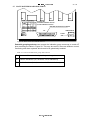
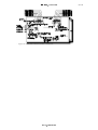
)$$021,72581,7,'0GRSWLRQ
The monitor has following functions which need to be adjusted with the actual
load during commissioning. The monitoring of lamp faults is based on a voltage
curve measurement and the monitoring of VA-drop is based on a RMS voltage
measurement.
VA-drop set level, step6
VA-drop set level, step5
VA-drop set level, step4
VA-drop set level, step3
VA-drop set level, step2
VA-drop set level, step1
Lamp fault set level, step1
Lamp fault set level, step2
Lamp fault set level, step3
Lamp fault set level, step4
Lamp fault set level, step5
Lamp fault set level, step6
MP= Measuring point
LF= Lamp fault
VA-REF, STEPS 1-6
D1 LFA D2 D1 LFB D2
LF reference level A
MP4
LF actual value
IREF
LF OFFSETS, STEPS 1-6
LF OFFSETS, STEPS 1-6
DIR1
LF reference level B
MP12
a1
DIR2
LF ACT
MP13
VA-drop
VA-drop
reference value
Current fault
Lamp fault A
LF SCALES
LF scaling
VA basic scaling
VA
REF
DIR1DIR2
MP3
Lamp fault B
Current reference
LF voltage polarity
LED 5
TEST
LEDS
6&7
VA DIR
VA-drop direction
selector
X2
X4
D
LFA LFB
LF SCALE
DIR S
VA
VA direction balancing
COM F
X9
Sum to common fault
LF U POL
CF
VA
LF U
POL
1 2
MP5
IREF
c3
LF voltage
polarity selector
X1
LF prescaling
VA-drop actual value
VA
ACT
N
I
MP15
Measuring point Gnd
IDMAN OY 01.03.1998 IDM 7000-03 / D
MP 1
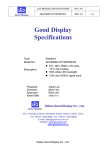
)LJXUH)$$PRQLWRUFDUG,'0G
/DPSIDXOWVHWWLQJV
The following tools are needed:
2 pcs TRMS multimeters
Small screw driver for trimmers
Trimmings and settings will be done as follows:
&KHFN WKDW DOO ODPSV DUH IXQFWLRQLQJ EHIRUH DGMXVWLQJ WKH ODPS IDXOW
PRQLWRU
2. Switch the CCR OFF and disconnect power by the main switch or main fuse.
3. Remove the FAA-monitor card.
4. Insert the extension board to CCR.
5. Connect the monitor card to the extension board.
6. Turn the power ON and switch the CCR ON.
7. Check the LED 5. If LED is bright clearly on each current step the jumper on
the terminal X1 is set to wrong position. Turn the power OFF and change
position of the jumper on the terminal X1 (LF voltage polarity selector).
1 1RUPDO, ,QYHUVH127( If the polarity of lamp fault voltage is opposite
the lamp fault voltage is negative.
8. Turn the power OFF. Connect VDC-meter between GND (MP1) and Iref
(MP5). Turn the power ON and check voltage. The current reference value
should be 0,50 VDC (Factory setting). If Iref is not correct adjust voltage to
0,50 V DC by trimmer Iref.
9. Turn the power OFF and connect VDC-meter to GND (MP1) and LF
ACT(MP13) Check that the jumper of the terminal X4 is set to position D
(decrease). If not, change it.
,'0$13KLOLSVOLJKWLQJ
,'0±8VHU0DQXDO
23 / 39
10.Turn the power ON and switch the lowest level ON (first step). Adjust the
”Offset” voltage to 0,00 V DC with trimmer LF OFFSETS STEP 1 (DIR1).
11.Disconnect one lamp from the circuit. Adjust or scale LF voltage to about 0,2 0,4 V DC with trimmer DIR 1 (LF SCALES).
12.Reconnect the lamp. Adjust again the ”Offset” voltage to 0,00 V DC with
trimmer LF OFFSETS STEP 1.
13.Change intensity to step 2 and adjust ”Offset” to 0,00 V DC with trimmer LF
OFFSETS STEP 2.
14.Repeat with steps 3 to 5 (or 6).
15.Basic calibration of lamp fault monitor is completed.
1H[WSURFHHGZLWKFKRRVLQJDQGVHWWLQJRIDODUPOLPLW$
1. Switch the CCR OFF and turn the power OFF.
2. Define and choose how many lamps shall give alarm A (LF A).
(Normally 5 - 10% of total amount)
3. Connect the first VDC-meter to MP1 (GND) and MP4 (LF A).
4. Connect the second VDC-meter to MP1 (GND) and MP13 (LF ACT).
5. Disconnect chosen amount of lamps from the circuit for the first alarm level A.
6. Turn power ON and switch CCR ON in step 1.
7. Read and note the actual lamp fault voltage (LF ACT).
8. Adjust LF reference value A slightly lower than LF ACT with trimmer LF A, D1.
Check that the test LED 6 (LF A) just lit up stabile. Record the LF A value up.
9. The setting of alarm level A is completed.
1H[WSURFHHGZLWKFKRRVLQJDQGVHWWLQJRIDODUPOLPLW%
1. Switch the CCR OFF and turn the power OFF.
2. Define and choose how many lamps shall give the second alarm B. (Normally
15% of total amount)
3. Disconnect chosen amount of lamps in the circuit.
4. Change the first VDC-meter to MP1 (GND) and MP12 (LF B).
5. Turn the power ON and switch the CCR ON in step 1.
6. Read and note the actual lamp fault voltage (LF ACT).
7. Adjust LF reference value B slightly lower than LF ACT with trimmer LF B,
D1.
Check that the test LED 7 (LF B) just lit up stabile.
8. Switch the CCR OFF
9. Reconnect the all lamps.
10. The setting of alarm level B is completed.
&KHFNWKHIXQFWLRQRIDODUPV
1. Switch the CCR ON. Disconnect lamps one by one with an interval of one
minute until the alarm level A comes. The first alarm should appear at chosen
amount of lamps. Detection of alarm is shown on the test LED’s before they
occur on the front of panel. Test and notify the function of the alarm on all
intensities by changing intensity step. Wait one minute for detecting alarms.
2. Disconnect more lamps until the alarm level B occurs. Proceed as above.
3. Checking and inspection is completed.
&&5ZLWKGLUHFWLRQFKDQJHU
If CCR is equipped with direction changer feature, the lamp fault trimming and
settings to direction 2 should be done in a same way as to direction 1. For
direction 2 the card has own trimmers. The trimmers have been marked by DIR2
,'0$13KLOLSVOLJKWLQJ
,'0±8VHU0DQXDO
24 / 39
or D2. Examples: (LF OFFSETS STEPS 1-6, DIR2), (LF SCALES, DIR2), (LF A,
D2) and (LF B, D2). 127( The current reference is a basic setting. The same
value is used for both directions. It is necessary to check and set it only once (in
direction 1). Also LF polarity selection is same to both directions.
9$GURSVHWWLQJV
9$GURSVFDOLQJ
1. Measure actual value of VA-drop with DC-voltmeter across measuring points
MP1 (GND) and MP15 (VA ACT)
2. If the CCR is with direction changer, do the scaling with the smaller load
(Direction 2) and balance the value of direction 1 to be equal to direction 2
with trimmer VA/dir.
3. 1RWHCCRs with direction changer: The jumper of VA-drop direction selector
is set to position 1 at the factory. If the smaller load is connected to direction 1
and the bigger load is connected to direction 2, the jumper of the terminal X2
must be changed to position 2.
4. Select the maximum brilliancy step and load (if CCR is with circuit selector)
and scale the actual value to 8V with trimmer VA/S. Maximum value depends
on ratio of CCR output power and load (4-8V is OK).
9$GURSLQGLFDWLRQ
1. Record the actual values (Uact) for each brilliancy step to the commissioning
test report.
2. Calculate the desired reference values for each step by using formula below.
8UHI
8DFW * (
100 [
)
100
Uref
desired reference voltage
Uact
measured actual values of a faultless circuit (V DC)
x power drop, in per cent, desired to cause alarm (normally 10%)
3. Measure reference value of VA-drop with DC-voltmeter across measuring
points MP1 (GND) and MP3 (VA REF)
4. Adjust the reference values for each brilliancy step with trimmers VA-drop 1-6
and record them to the commissioning test report.
2WKHUVHWWLQJ
1. &RPPRQ IDXOW LQGLFDWLRQ selector will abort Cf (current fault) and VA-drop
alarms from the common fault alarm and thus will leave only mains failure
indication to the common fault.
,'0$13KLOLSVOLJKWLQJ
,'0±8VHU0DQXDO
25 / 39
(;75$021,72581,7,'0DRSWLRQ
The card includes extra monitoring functions with over current protection. Settings are pre-set
at the factory.
)LJXUH([WUDPRQLWRUFDUG,'0D
D%DVLFFDOLEUDWLRQ
Connect DC volt meter to test points MP0(ground) and Iact (actual value).
Select the highest brilliancy and check that the reading is same as the reading on
CCR’s current meter. Adjust with trimmer, P1 if needed.
Current measuring on the card is based on rectifying and is not exactly the same as TRMSvalue. If meter is calibrated with 6,6A reading with 3,3A is approximately 3A.
E&XUUHQWLQGLFDWLRQ
Select the lowest current step and check the ”current on” limit from the test points
MP0(ground) and Uc. Normal value is 1,5V (=1,65A). Check also that the green LED
is on and the indication relay operates.
Adjust ”current on” limit higher than the actual value (>3A) whit trimmer P2. Check
that LED turns off and relay operates (connect is open).
Set the limit back to 1,5V(=1,65A).
F2YHUFXUUHQWSURWHFWLRQ
Connect the highest current step and turn the current trimmer OC1 counter-clockwise
until the CCR strips.
Turn the trimmer 1/3 turn clockwise.
,'0$13KLOLSVOLJKWLQJ
,'0±8VHU0DQXDO
26 / 39
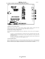
($57+)$8/7021,725,'0RSWLRQ
)LJXUH(DUWKIDXOWPRQLWRUFDUG,'0
The unit monitors the isolation resistance on which two alarm levels can be set.
The ref values can be checked from points MP0 (gnd), MP1 (ef a) and MP2
(ef b).
The ref values can be adjusted with trimmers P1 (level a) and P2 (level b).
Factory settings are 1Mohm (level a) and 100 kohm(level b).
Actual value can be checked from measuring points MP0 and MP3.
Desired ref values can be taken from figure 19.
)LJXUH5HIHUHQFHYROWDJH9'&DVDIXQFWLRQRIWKHLVRODWLRQUHVLVWDQFH
,'0$13KLOLSVOLJKWLQJ
27 / 39
,'0±8VHU0DQXDO
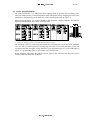
0$,1027+(5%2$5','0
X6
X1
Potential grouping
X7 pin Gnd Com1Com2
7
8
23
Jumpers
1,2
R,PI,FI
2,3
R
PI,FI
PI
FI
3,4
R
1,4
R,FI
PI
R
2,4
PKR
1.
4.
X2
X3
X10
R=Relay Gnd
PI=Positive indication common
FI=Fault indications common
Remote control D-25 connector
PI,FI
IDM 7000-04
X7
13
25
1
14
Fuses
1A
f1
f2
)LJXUH0DLQPRWKHUERDUG,'0
3RWHQWLDOJURXSLQJVHOHFWRU can connect the indication group commons to certain X7
pins according the table in Figure 20. This may be useful if there are different control,
monitoring and alarm systems which need to be galvanically isolated.
7DEOH&RQWURODQGLQGLFDWLRQJURXSDEEUHYLDWLRQV
-R
Common of the control relays, always to be gnd.
-PI
Positive indications (On, direction, circuit indications)
-FI
Fault indications (Local, remote and all fault indications)
,'0$13KLOLSVOLJKWLQJ
,'0±8VHU0DQXDO
28 / 39
&,5&8,76(/(&725027+(5%2$5','0
)LJXUH&LUFXLWVHOHFWRUPRWKHUERDUG,'0D
D5HPRWHFRQWUROYROWDJHVHOHFWRU
Check that the remote control voltage selector settings conform with the voltage used in the
system. 24/48/60V DC can be selected with jumpers PR1-PR6 for each circuit.
E,QGLFDWLRQSRWHQWLDOJURXSLQJVHOHFWRU
With Indication potential grouping selector the indications of the circuits can be arranged as
follows.
Log (Pos 1). Circuit indications are connected to positive indications (PI) of the main
mother board and are mastered by the on relay. The indications are only given when
the regulator is on .
Ind (Pos 2). Indications are grouped to X13/14 terminal (Control relays common) and
the indications are given even if the regulator is off.
F&LUFXLWHQDEOHVHOHFWRU
Selector defines which circuits are used. On-position means that the circuit is enabled and off
that it is disabled. This function is related with the lamp fault and VA-drop monitoring
functions and need only be changed if the number of circuits in the CCR is modified.
,'0$13KLOLSVOLJKWLQJ
,'0±8VHU0DQXDO
29 / 39
0$,175$16)250(5
The main transformer T1 is fitted with three tappings both on primary and secondary sides.
This is to match possibly oversized regulator better with actual load by changing the ratio of the
transformer. The matching can be done in 5% steps according the table in Figure 22.
Please note that approx. 5% reserve should be left for under voltage conditions and that the
adjusting should be done first on the secondary side.
)LJXUH)LWWLQJD&&5WRORDGZKLWGLIIHUHQWVXSSO\YROWDJHV
The matching is done by connecting the transformers incoming line wire to one of the terminals
1A1,1A2 and 1A3.And respectively the outgoing line cable to one of the terminals 1a1,1a2 and
1a3.Please note that no higher voltage should be given to primary taps as is given in the table of
Figure 22. eg connecting 240V to 1A1 (220V tap) is not allowed
Proper matching will reduce the primary current, improve the efficiency and the power factor
and also reduce the harmonic distortion.
,'0$13KLOLSVOLJKWLQJ
,'0±8VHU0DQXDO
&200,66,21,1*&+(&./,67
1 Check the afl-circuit
-Load
-Continuity
-Isolation
2 Remote control and pre-set settings
-Remote control voltage settings ;logic unit and circuit selector
mother board
-D-mode selector ; logic unit
-Potential grouping settings ; main and circuit selector mother boards
-Main transformer tapping
3 Calibrations/regulator card
-Basic calibration 1A=1V
-A/V -meters
Protections/regulator card
-Open circuit
-Over current settings
-limiter
Performance/regulator card
-Current step settings
-Low current level
FAA-monitor
-Lamp fault; off-set (null), scaling, actual and set values
-10% VA-drop ; scaling, actual and set values
-Reset type
Extra monitor
-Calibration
-Current indication
-Over current protection
Earth fault monitor
-Actual and set values
Remote control function test
-Controls, logic unit and circuit selector mother board
-Indications
,'0$13KLOLSVOLJKWLQJ
30 / 39
,'0±8VHU0DQXDO
31 / 39
7528%/(6+227,1*
The regulator is set up on plug in euro cards. Trouble shooting is practical to do
simply by replacing new cards. Please note following remarks:
7XUQWKH&&5RIIZKHQUHSODFLQJFDUGV
8VHWHVWORDGGXULQJWURXEOHVKRRWLQJLISRVVLEOH
6833/<92/7$*(&+(&.
This check should be done always after serious damage (for instance lightning)
or when power - LED does not lit despite that the CCR is on.
Take off all the with drawable cards.
Measure the DC power given to the regulator card (7000-02) with the
extension card.
7DEOH,QFRPLQJSRZHUYROWDJHVIRUWKHUHJXODWRUFDUG
&RQQHFWRU 9ROWDJH'&
H[SODQDWLRQ
28c/30c
+20 V DC
Power +
28c/30a
-20 V DC
Power -
If voltages are not correct, check the mother board and the DC power
transformer T4.
If voltages are OK, insert the 7000-02 card and measure following DC
voltages.
7DEOH3RZHUYROWDJHVSURYLGHGE\WKHUHJXODWRUFDUG
&RQQHFWRU 9ROWDJH'&
H[SODQDWLRQ
28c/2c
+12 VDC
Regulated +DC supply
28c/2a
-12 VDC
Regulated -DC supply
28c/26c
+5 VDC
supply for meters
28c/26a
+24 VDC
supply for relays
If the given voltage values are not correct, replace the regulator card. Please note that
incorrect values may damage the other cards
If values are OK you may try inserting the other plug in cards.
&&5:,//12767$57$7$//
Check the supply voltage and fuses. The supply voltage can be easily seen from the
"Power" led on the logic unit provided that the main switch is on.
Check if % led is lit on the logic card when switched on. If not replace the logic card.
,'0$13KLOLSVOLJKWLQJ
,'0±8VHU0DQXDO
32 / 39
&&5*,9(6$123(1&,5&8,7$/$50
Check continuity of the secondary circuit
Check the open-circuit protection level (Uc)
Start the CCR and check following.
If current is practically 0A and voltage gets very high, check the current trafo and
its wiring ,power circuit wirings and components and change the regulator card if
necessary.
If the current and voltage are too low, check the current set level and change the
regulator card if necessary.
If the current and voltage starts normally, check the open-circuit protection level.
&&5*,9(6$129(5&855(17$/$50
Check the over-current set levels (Oc1 and Oc2)
Check the fuses and the power voltages of the regulator card
If possible use test load and try CCR with the lowest brilliancy step
Check the brilliancy step levels and change the regulator card if necessary
&&5,621%87&855(176((0672%(8167$%/(
Check the grounding of the CCR. Bad grounding can cause unstability to sensitive electronic
circuits especially with larger CCRs.
0$,1)86(,6%/2:1
'RQRWWU\WRVWDUWEHIRUHFRPSRQHQWDQGZLULQJFKHFNV
Check power circuit for short circuits and also isolation against the ground.
Check the thyristor module, thyristor controller and the regulator card
Do not try to start many times if the fuse blows but instead check carefully each
component of the circuit.
,'0$13KLOLSVOLJKWLQJ
,'0±8VHU0DQXDO
33 / 39
0$,17(1$1&(
35(9(17,9(0$,17(1$1&(
A maintenance programme, including preventive maintenance where appropriate, should be
established at an aerodrome to maintain facilities in a condition which does not impair the
safety, regularity or efficiency of air navigation. (ICAO Annex 14, 2:nd edit. page 109)
According to ICAO Annex 14 a light fitting is unserviceable when:
It’s main beam is out of alignment
It’s average intensity is below 50% of the specified value.
Preventive maintenance requirements are divided into following categories.
&$7,,&$7,,,SUHYHQWLYHPDLQWHQDQFHUHTXLUHPHQWV
All approach and runway lights are serviceable and in all cases at least as in Table 13.
7DEOH$YDLODELOLW\RID&$7,,DQG&$7,,,V\VWHPV
6HUYLFHDELOLW\
95%
/LJKWLQJVXEV\VWHP
CAT II and CAT III approach lighting system (innermost 450 m)
Runway centreline lighting system
Threshold lighting system
Runway edge lighting system
90%
Touchdown zone lighting system
85%
Approach lighting system
75%
Runway end lighting system
Lighting pattern must keep its form despite of light fitting failures.
Failure in two adjacent light fittings is not permitted except in a barrette or a cross-bar where
two adjacent light fitting failures are permitted.
3UHYHQWLYHPDLQWHQDQFHUHFRPPHQRIWKHVWRSEDUOLJKWLQJV\VWHP595P
Maximum two light fittings are unserviceable.
Two adjacent fittings are not faulty unless the spacing between them is reduced.
3UHYHQWLYH PDLQWHQDQFH UHFRPPHQGDWLRQV RI WKH WD[L ZD\ OLJKWLQJ V\VWHP
595P
No two adjacent fittings are unserviceable.
,'0$13KLOLSVOLJKWLQJ
,'0±8VHU0DQXDO
34 / 39
&$7,SUHYHQWLYHPDLQWHQDQFHUHFRPPHQGDWLRQV
All approach and runway lights are serviceable and in all cases at as shown in
Table 14. 7DEOH$YDLODELOLW\RID&$7,V\VWHP
6HUYLFHDELOLW\
/LJKWLQJVXEV\VWHP
85%
Approach lighting system
Threshold lighting system
Runway edge lighting system
Runway end lighting system
Lighting pattern must keep its form despite of light fitting failures.
Failure in two adjacent light fittings is not permitted unless the spacing between them
is reduced.
3UHYHQWLYHPDLQWHQDQFHUHFRPPHQGDWLRQVRI595PWDNHRIIUXQZD\
All runway lights are serviceable and in all cases at least as shown in Table 15.
7DEOH$YDLODELOLW\RID595!PV\VWHP
6HUYLFHDELOLW\
/LJKWLQJVXEV\VWHP
95%
Runway edge lighting system, runway centre line lighting system
75%
Runway end lighting system
No two adjacent light fitting failures are permitted
3UHYHQWLYHPDLQWHQDQFHUHFRPPHQGDWLRQVRI595!PWDNHRIIUXQZD\
All runway lights are serviceable and in all cases at least as shown in Table 16.
7DEOH$YDLODELOLW\RID595!PV\VWHP
6HUYLFHDELOLW\
85%
/LJKWLQJVXEV\VWHP
Runway edge lighting system
Runway end lighting system
No two adjacent light fitting failures are permitted
)XOILOOPHQWRI,&$2VSUHYHQWLYHPDLQWHQDQFHREMHFWLYHV
The objective of ICAO cannot be yet fullfilled because at the moment the aligning and
light output of each light fitting cannot be monitored at reasonable costs. The serviceability is
monitored by monitoring the lamp filament and is done in two ways:
Centralised system is realized with a lamp failure monitor in a CCR.
In a distributed system each light fitting has an addressable monitoring unit.
&HQWUDOLVHGV\VWHPZLWK,'0)$$PRQLWRU
Reference levels should be set equal and according the preventive maintenance tables for each
CCR of a subsystem. Alarms should be connected parallel. First CCR which reaches the level
causes the alarm.
,'0$13KLOLSVOLJKWLQJ
,'0±8VHU0DQXDO
35 / 39
'LVWULEXWHGPRQLWRULQJV\VWHPV
In distributed monitoring systems every light fitting has an addressable monitoring unit. In this
case the percentage values and adjacency requirements can be monitored more efficiently.
However even then the first objective of ICAOs recommendation: all fittings serviceable, can
not be fulfilled.
0$,17(1$1&(2)7+(&&5
Following things should be checked at least on a yearly basis.
Calibration of the meters
Basic calibration
Protections levels and functions
Ventilation is not blocked
The afl-circuit isolation resistance should be regularly checked and tables made
to follow the condition of the circuits in time and different weather conditions. Pay
attention to next things.
Disconnect the CCR from the circuit when checking the isolation resistance
specially if the regulator is supplied with earth fault monitor.
Discharge the circuit after measuring before touching the cables
When CCR is switched on, 100 VDC measuring voltage is connected into the
circuit.
Following spare parts are recommended to be kept in stock at site.
Logic card
Regulator card
Thyristor pair
Thyristor controller
Fan
,'0$13KLOLSVOLJKWLQJ
,'0±8VHU0DQXDO
36 / 39
,'0&$5'9(56,216
As we continuously develop our products following card versions with new
features have been developed. The card pictures in this document conform with
the latest card versions.
7DEOH&DUGYHUVLRQV9 FDUGYHUVLRQ' JHQHUDWLRQ
&DUG
9 '
'DWH
)HDWXUH
01
a
A
15.10.1993
Logic card
b
C
1.1.1995
Binary coding, direction chance
a
A
15.10.1993
Regulator card
b
B
1.4.1994
Voltage supervisions
a
A
15.10.1993
Monitor card
b
C
1.8.1995
Balancing of direction chance, A/B level control
d
D
01.03.1998
New method of lamp fault monitoring chanced
a
A
15.10.1993
Main mother card
b
B
1.4.1994
Extra monitor, fault definition, step relays
c
C
1.1.1995
Chances for 03b
a
A
15.10.1993
Earth fault monitor card
b
B
1.4.1994
Test points, trimming of the resistance meter
06
a
A
1.10.1993
Base card for earth fault monitor card
07
a
A
15.4.1993
Circuit selector card
08
a
A
1.10.1993
Base card circuit selector card
09
a
B
1.4.1994
Extra-monitor card
02
03
04
05
Cards are compatible with earlier versions, however naturally the new features
do not work in connection with cards of earlier generation.
&86720(5)(('%$&.5(&/$0$7,216$1'$)7(56$/(66(59,&(6
As we also develop our products through customer feedback we welcome all
comments regarding the quality and performance of the CCR. Reclamations are
statistically filed and corrective actions taken immediately. Full repair service is
provided for the cards.
Training and commissioning services are also available.
,'0$13KLOLSVOLJKWLQJ
,'0±8VHU0DQXDO
37 / 39
7(&+1,&$/'$7$
Input voltage
230V +10/-5% , 50/60 Hz , single phase
Output current
6.6A+1%, regulation from 1,5 to 6.6A 5/6 steps
Power ratings
3; 4; 5; 7,5; 10; 12; 15; 17,5; 20; 25 kVA
In output connectors, Whit nominal values, matching posipility 30%
Power factor
> 0,95, with rated load and with rated supply voltage
Efficiency
> 90%, with rated load and with rated supply voltage
Remote control
24/48/60 V DC selectable, Connection with D-connector
Ambient temp
-0 C to +55 C, on request from -40 C to +55 C
Protections
Over current/primary, fuses
Over current/secondary, electronic, 2-levels, tripping
open circuit/ secondary, electronic, tripping
Under voltage/ primary, electronic, tripping
Monitors
10% VA-drop ,electronic, all brilliancy steps, 2 directions
Current fault, electronic, all brilliancy steps
Lamp fault, electronic, 2-levels, all steps, 2 directions
Earth fault, electronic, 2-levels
Meters
Ampere (A), TRMS, digital
Volt (V), TRMS, digital
M-ohm (earth fault), analogy meter
Total operating hours, mechanical, digital
100% operating hours, mechanical, digital
Dimensions
Width: 660 mm Depth 500 mm
Height 450 mm < 5 kVA
900 mm 5-15 kVA
1350 mm >15 kVA
Accessories
IDM 7000-RT remote control tester
IDM 7500-CT remote control simulator
IDM 7000-IS Installation rack system
,'0$13KLOLSVOLJKWLQJ
,'0±8VHU0DQXDO
$33(1',;($5/,(5&$5'9(56,216
)LJXUH,'0DORJLFFDUGOD\RXW
)LJXUH,'0DUHJXODWRUFDUGOD\RXW
)LJXUH,'0D)$$PRQLWRUFDUGOD\RXW
,'0$13KLOLSVOLJKWLQJ
38 / 39
,'0±8VHU0DQXDO
)LJXUH,'0E)$$PRQLWRUFDUGOD\RXW
,'0$13KLOLSVOLJKWLQJ
39 / 39