1
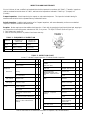
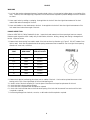
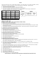
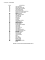
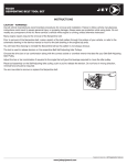
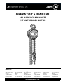
OPERATOR'S MANUAL
L90 MODEL CHAIN HOISTS
½TON THROUGH 10 TON
BRANCHES:
Vancouver
3260 Production Way
Burnaby, B.C.
V5A 4W4
Tel:(604) 444-5300
Toll free:1-800-472-7685
Fax:(604) 444-9227
Edmonton
4120 - 78 Avenue NW
Edmonton, Alberta
T6B 3M8
Toll free:
Tel: 1-800-468-1628
Fax: 1-800-663-7742
Winnipeg
951 Powell Avenue
Winnipeg, Manitoba
R3H 0H4
Tel:(204) 632-6970
Toll free:1-800-665-7524
Fax:(204) 694-9534
Toronto
416 Watline Avenue
Mississauga, Ontario
L4Z 1X2
Tel:(905) 502-8665
Toll free:1-800-387-3879
Fax:(905) 502-7707
www.jetequipment.com
Montreal
4620 rue Garand
St-Laurent, Quebec
H4R 2A2
Sans frais:
Tel:1-800-363-2885
Fax:1-800-267-3310
Halifax
#123-11 Morris Drive
Dartmouth, Nova Scotia
B3B 1M2
Tel:(902) 468-8324
Toll free:1-800-472-7686
Fax:(902) 468-3461
TABLE OF CONTENTS
WARRANTY POLICY . . . . . . . . . . . . . . . . . . . . . . . . . . . . . . . . . . . . . . . . . . . . . . . . . . . . . . . . . . . . . . . .
INFORMATION FOR YOUR SAFETY . . . . . . . . . . . . . . . . . . . . . . . . . . . . . . . . . . . . . . . . . . . . . . . . . . . . . .
PRIOR TO INSTALLATION . . . . . . . . . . . . . . . . . . . . . . . . . . . . . . . . . . . . . . . . . . . . . . . . . . . . . . . . . . . . .
SAFETY PRECAUTIONS . . . . . . . . . . . . . . . . . . . . . . . . . . . . . . . . . . . . . . . . . . . . . . . . . . . . . . . . . . . . . .
INSPECTION AND MAINTENANCE . . . . . . . . . . . . . . . . . . . . . . . . . . . . . . . . . . . . . . . . . . . . . . . . . . . . . .
HOOKS . . . . . . . . . . . . . . . . . . . . . . . . . . . . . . . . . . . . . . . . . . . . . . . . . . . . . . . . . . . . . . . . . . . . . . . . . . .
CHAIN . . . . . . . . . . . . . . . . . . . . . . . . . . . . . . . . . . . . . . . . . . . . . . . . . . . . . . . . . . . . . . . . . . . . . . . . . . .
PARTS BREAKDOWN . . . . . . . . . . . . . . . . . . . . . . . . . . . . . . . . . . . . . . . . . . . . . . . . . . . . . . . . . . . . . . . .
1
1
2
2
3
4
5
6
ONE YEAR LIMITED WARRANTY
JET™ Manual Hoists are guaranteed to be free of defects in material and workmanship. If one of these products fails during the
first year of operation due to defective material or workmanship it will be repaired or replaced at our discretion. Normal wear and
tear on moving parts is excluded from this guarantee. This guarantee does not apply to any product showing signs of misuse,
overloading, alteration, or improper maintenance.
WARRANTY PROCEDURE
After receiving authorization from one of the offices listed below, any product for which there is a warranty claim must be
returned prepaid to an authorized JET™ warranty depot along with proof of purchase.
Addresses for information on JET™ Material Handling products, warranty depots or distributors:
Vancouver
3260 Production Way
Burnaby, B.C.
V5A 4W4
Tel: (604) 444-4336
Fax: (604) 444-9227
Edmonton
4120 - 78 Avenue NW
Edmonton, Alberta
T6B 3M8
Tel: (403) 468-1618
Fax: (403) 466-9879
Winnipeg
1326 Border Street
Winnipeg, Manitoba
R3H 0M8
Tel: (204) 632-6970
Fax: (204) 694-9534
Toronto
6830 Rexwood Road
Mississauga, Ontario
L4V 1L8
Tel: (905) 677-2103
Fax: (905) 677-8008
Montreal
4620 Rue Garand
St-Laurent, Quebec
H4R 2A2
Tel: (514) 332-4612
Fax: (514) 332-4777
Halifax
#123-11 Morris Drive
Dartmouth, Nova Scotia
B3B 1M2
Tel: (902) 468-8324
Fax: (902) 468-3461
INFORMATION FOR YOUR SAFETY
It is the responsibility of the owner/user to install, inspect, test, maintain, and operate these hand chain hoists in accordance with
ASME B30.16, Safety Standard for Overhead Hoists.
These general instructions deal with the normal installation, operation and maintenance situations encountered with the hand chain
hoists described herein. The instructions should not be interpreted to anticipate every possible contingency or to anticipate the final
system or configuration that uses these hand chain hoists.
These instructions include information for a variety of hand chain hoists. Therefore, all instructions and information may not
apply to one specific hand chain hoist. Disregard those portions of the instructions that do not apply.
If the hand chain hoist owner/user requires additional information, or if any information in these instructions is not clear, contact
your local JET ™ chain hoist distributor.
This hand chain hoist should not be installed, operated, or maintained by any person who has not read all the contents of these
instructions, and ASME B30.16, Safety Standard for Overhead Hoists. Failure to read and comply with these instructions or any
of the warnings or limitations noted herein can result in serious bodily injury or death, and/or property damage.
Only trained and qualified personnel shall operate and maintain this equipment.
Equipment described herein is not designed for, and should not be used for lifting, supporting, or transporting people.
User should not use this hand chain hoist in conjunction with other equipment unless necessary and/or required safety devices
applicable to the system are installed by the user.
Modifications to upgrade, rerate or otherwise alter these hand chain hoists shall be authorized only by the original equipment
manufacturer or qualified professional engineer.
1
PRIOR TO INSTALLATION
Check for damage during shipment. Place claim with carrier if any damage is discovered. DO NOT install or use a damaged
hand chain hoist.
Check and verify that structure or other equipment that will support the hand chain hoist has a rated load capacity equal to or
greater than the rated load capacity of the hand chain hoist to be used.
OPERATION
Before initital operation of hoist:
1. Read and comply with all instructions and warnings furnished with or attached to hoist.
2. Check lubricant.
3. Check operation of brake.
4. Check that chain is properly seated in sheaves and that chain is not twisted, kinked, or damaged.
Before each shift:
1. Inspect hooks for nicks, gouges, cracks, and signs of pulling apart or twisting.
2. Inspect hook latch for proper operation.
3. Check chain for kinks or twists.
4. Check operation of brake.
5. Replace warning label if missing or illegible.
Before operating:
1. Be certain all personnel are clear of the load to be lifted and moved.
2. Make sure load will clear stock piles, machinery, or other obstructions when hoisting and travelling the load.
3. Eliminate any twists or kinks in the load chain.
SAFETY PRECAUTIONS
A. READ these instructions and ASME B30.16, Safety Standard for Overhead Hoists before installing, operating, or maintaining
this equipment.
B. WARN personnel of approaching loads.
C. DO NOT
1. Lift more than rated load.
2. Operate hoist when it is restricted from forming a straight line with the direction of loading.
3. Operate with twisted, kinked, or damaged chain.
4. Operate if chain is not seated in sheaves or sprockets.
5. Wrap chain around load or use chain as a sling.
6. Operate unless load is properly applied to the saddle or bowl of the hook.
7. Operate if load is applied to the tip of the hook.
8. Operate with damaged or missing hook latches.
9. Lift people or lift loads over people.
10. Operate with side-pulling or side-loading of load to hoist.
11. Operate a damaged or malfunctioning hoist.
12. Operate with other than hand power.
13. Remove, deface, or obscure warning label or labels on hoist.
14. Leave load suspended when hoist is unattended unless specific precautions have been instituted and are in place.
15. Lengthen load chain or repair damaged load chain by welding.
16. Use chain as a ground for welding.
2
INSPECTION AND MAINTENANCE
Prior to initial use, all new, modified, and repaired hoists shall be inspected in accordance with Table 2. Thereafter, inspections
shall be conducted at intervals shown in Table 1; and items to be inspected are indicated in Table 2 by F (Frequent) or P
(Periodic).
Frequent Inspections - Visual inspection by the oeprator or other authorized person. This inspection includes listening for
unusual sounds while the hoist is operated that may indicate deficiencies.
Periodic Inspections - Audible-visual inspection as for Frequent Inspections, with some disassembly to allow a more detailed
inspection if external conditions indicate the need.
Exception: Brakes require more than audible-visual inspection. Check daily by operating hoist with and without load, stopping at
various positions to test holding power and amount of drift, if any occurs. TO ADJUST BRAKE (Refer to Figure 1):
1. Fully tighten nut to position A.
2. Slack off nut from position A to position B and insert cotter key.
TABLE 1 - FREQUENCY OF INSPECTION
SERVICE
FREQUENT (F)
INSPECTION
PERIODIC (P)
INSPECTION
Normal
Monthly
Annually
Heavy
Weekly to Monthly
Semi-Annually
Severe
Daily to Weekly
Quarterly
TABLE 2 - INSPECTION CHART
In chart, F indicates Frequent Inspection, P indicates Periodic Inspection
LOCATION
Braking mechanism
CHECK FOR
F
Slipping under load
T
Hard to release
T
P
LOCATION
Brake Parts
P
T
Not tight or secure
Hook Latch
Damaged; does not close
Excessive wear
Distortion
T
Broken or worn teeth
T
T
Oil contamination
T
Suspension Members
(Sheaves,hand-wheels, chain
attachments, suspension bolts or
pins)
Pawl; Ratchet
Excessive wear
T
Gears
Pawl Spring
Corrosion; stretch
T
Hooks
F
Hook Retaining
Members
(Pins, Bolts, Nuts)
Glazing
Brake Discs
CHECK FOR
Cracks
T
T
T
T
Chemical damage
T
Cracks
T
Deformation
T
Inadequate lubrication
T
5% in excess of normal throat
opening
T
10E twist from plane of unbent hook
T
Cracks (dye penetrant, magnetic
particle, or other suitable detection
method)
T
Load Block; Suspension
Housing
Distortion
T
T
Cracks
T
T
Trolley; Supporting Structure
Possible inability to
continue supporting
imposed loads
T
Bolts, Nuts, Rivets
Not tight or secure
T
WARNING Label
Removed or illegible
Refer to ASME B30.16 for additional information on inspection, test, and maintenance.
3
T
HOOKS
WARNING
1. Any hook that requires replacement because of excessive bends, twists, or throat opening indicates abuse or overloading of the
hoist. Therefore, other load-supporting components of the hoist should be inspected for possible damage when such conditions
are found.
2. Never repair hooks by welding or reshaping. Heat applied to the hook will alter the original heat treatment of the hook
material and reduce the strength of the hook.
3. Never weld handles or other attachments to the hook. Heat applied to the hook will alter the original heat treatment of the
hook material and reduce the strength of the hook.
HOOKS INSPECTION
Refers to ASME B30.10, Safety Standard for Hooks. Inspect hooks and measure hook throat opening at least once a month.
Between regular inspections check visually daily for deformation, distortion, twisting, damage, and missing or damaged hook
latches. Inspect as follows:
1. Measure hook throat opening from metal to metal of the hook as shown by dimension g in Figure 2. DO NOT measure from
latch to metal. Hook must be replaced when throat opening measurement has increased 5% over the original throat opening
dimension of a new hook, as follows:
CAPACITY
TONS
DIMENSION g
NEW HOOK
DIMENSION g
REPLACE HOOK
1/2
30mm
31.5mm
1
34mm
35.7mm
1-1/2
39mm
40.9mm
2
43mm
45.2mm
3
50mm
52.5mm
5
58mm
60.9mm
10
70mm
73.5mm
2. Measure hook depth at load bearing point (base, bowl or saddle) of the hook. Hook must be replaced when wear at load
bearing point is 10% of the original depth of the hook load bearing point.
3. A bend or twist of the hook exceeding 10E from the plane of the unbent hook requries replacement of the hook.
4. A hook latch that is missing shall be replaced.
5. A hook latch that is inoperative shall be repaired or replaced.
6. A hook with a hook latch that does not close the throat opening of the hook shall be removed from service until the latch
is replaced or repaired.
7. Hooks having damage from chemicals, corrosion, or deformation shall be repaired or replaced.
4
CHAIN
Inspect chain at least once a month. Between regular inspections, check visually daily for nicks, gouges, weld splatter, corrosion,
or distorted links. Inspect chain thoroughly if it does not feed smoothly over load sheaves. Inspect as follows:
1. Clean chain with solvent before inspection.
2. Test hoist with load and observe operation of chain over load sheaves.
3. Slacken chain and inspect contact points for excessive wear. Refer to Figure 3.
4. Using caliper-type gauge, measure inside length of 5 links under light tension. Refer to Figure 4. Replace chain if
measurement exceeds maximum allowable gauge length as follows:
CAPACITY
TONS
CHAIN WIRE
DIAMETER
5 LINKS
NORMAL
5 LINKS
MAXIMUM
1/2
5.0mm
75mm
77.6mm
1
6.3mm
95mm
98.3mm
2
8.0mm
120mm
124.1mm
1-1/2 and 3
7.1mm
105mm
108.6mm
5 and 10
9.0mm
135mm
139.6mm
INSTALLING LOAD CHAIN
WARNING: DO NOT ADD TO LOAD CHAIN; REPLACE ENTIRE CHAIN
To install load chain into load chain sprocket:
1. Position load chain sprocket by rotating handchain wheel so that wide and narrow grooves show.
2. Using a forked poker, insert top chain link into sprocket grooves so that chain will wind up and back over sprocket. Welds
must be away from sprocket.
3. Rotate handchain wheel so that load chain winds around sprocket. Stop when chain falls 6 to 8 inches at back of sprocket.
4. Attach end link of the load chain to the chain anchor.
To install load chain anchor when replacing old chain:
1. Remove cotter pin and chain anchor pin on chain anchor.
2. Insert bottom chain link into chain anchor.
3. Insert chain anchor pin through anchor brackets and chain link.
4. Insert cotter pin through hole in anchor pin and secure.
To install load chain into lower hook (1/2, 1, 1-1/2, and 2 ton):
1. Remove cotter pin from castle nut and remove nut.
2. Insert last chain link into lower hook slot. Check that chain is not twisted.
3. Insert chain bolt into lower hook slot.
4. Insert chain bolt through lower hook slot and chain link.
5. Secure castle nut to end of bolt.
6. Insert cotter pin into castle nut and secure.
To install load chain into lower hook (3, 5, and 10 ton):
1. After installing load chain into load chain sprocket, run remaining chain through hands, removing any twist. Last link of
chain must be in same direction as first. If not, cut off last link.
2. Insert last link into left-hand pulley of lower hook. Pull chain through and up from underside of pulley.
3. Check that chain stopper is on right-hand side.
4. Insert last link into right-hand pulley of upper hook, moving chain up, back, then down. Check that chain is not twisted and
welds face away from pulley.
5. Insert last link into right-hand pulley of lower hook, pulling up from underside of pulley. Check that chain is not twisted.
6. Insert last link over left-hand pulley of upper hook, moving chain up, back, then down.
7. To prevent free-wheeling of chain, insert screwdriver securely into link at base of upper pulley.
8. Remove cotter pin, castle nut, and chain bolt in lower hook slot.
9. Insert last link into slot.
10. Check that chain is not twisted.
11. Position bolt back through lower hook slot and last chain link.
12. Place castle nut onto end of bolt.
13. Secure cotter pin in tapered hole of bolt.
14. Remove screwdriver from link at base of upper pulley.
Install load chain for 3 ton and 5 ton hoists in same manner as above but allow for fewer falls of chain.
5
6
L-90 1/2 TON - 5 TON MODEL
ITEM#
DESCRIPTION
001
002
003
007
015
016
TOP HOOK ASSY
GEAR SIDE PLATE ASSY
WHEEL SIDE PLATE ASSY
LOAD SHEAVE ASSY
BOTTOM HOOK ASSY
SAFETY LATCH ASSY (OLD STYLE)
SAFETY LATCH ASSY (NEW
STYLE)
GEAR CASE ASSY
2ND & 3RD GEAR ASSY
STRIPPER ASSY
TOP HOOK PIN
STAY BOLT
COVER NUT
WASHER
HAND WHEEL COVER
CHAIN STOP PIN
ANCHOR PLATE
ANCHOR PLATE PIN
DRIVING SHAFT
DRIVING SHAFT WASHER
LOAD GEAR
CASTLE NUT
CASTLE NUT PIN
LOAD METAL
LOAD SHEAVE COVER
LOAD SHEAVE COVER PIN
HAND CHAIN WHEEL
DISC HUB
RATCHET GEAR
FRICTION DISC
CHECK WASHER
PAWL
PAWL PIN
PAWL SPRING
BRAKE COVER
FRICTION DISC
CHAIN STOP BOLT ASSY
NAME PLATE
RIVET
023
024
027
105
203
205
206
218
221
225
226
301
302
305
308
312
404
405
433
501
505
506
507
508
510
511
512
513
517
604
940
941
BE SURE TO STATE TONNAGE WHEN ORDERING PARTS
L-90 10 TON MODEL
ITEM#
001
002
003
007
015
016
023
024
027
105
203
205
206
218
221
225
226
301
302
305
308
312
404
405
433
501
505
506
507
508
510
511
512
513
517
604
940
941
DESCRIPTION
TOP HOOK ASSY
GEAR SIDE PLATE ASSY
WHEEL SIDE PLATE ASSY
LOAD SHEAVE ASSY
BOTTOM HOOK ASSY
SAFETY LATCH ASSY
GEAR CASE ASSY
2ND & 3RD GEAR ASSY
STRIPPER ASSY
TOP HOOK PIN
STAY BOLT
COVER NUT
WASHER
HAND WHEEL COVER
CHAIN STOP PIN
ANCHOR PLATE
ANCHOR PLATE PIN
DRIVING SHAFT
DRIVING SHAFT WASHER
LOAD GEAR
CASTLE NUT
CASTLE NUT PIN
LOAD METAL
LOAD SHEAVE COVER
LOAD SHEAVE COVER PIN
HAND CHAIN WHEEL
DISC HUB
RATCHET GEAR
FRICTION DISC
CHECK WASHER
PAWL
PAWL PIN
PAWL SPRING
BRAKE COVER
FRICTION DISC
CHAIN STOP BOLT ASSY
NAME PLATE
RIVET