1
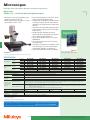
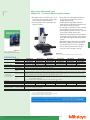
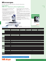
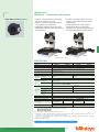
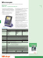
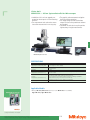
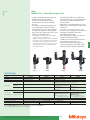
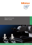
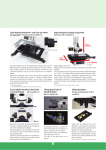
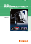
Microscopes
Microscope lineups that systemize observation, measurement and processing
MF series
SERIES 176 — Measuring Microscopes
J
•Observationwithaclearandflarelesserect •Illuminationunit(reflected/transmitted)can
image along with a wide field of view.
beselectedfromahigh-intensityLEDor
•Measuringaccuracyisthehighestinitsclass
halogen bulb.
(andconformstoJISB7153).
•Variableaperturediaphragm(reflected/
•MLseries,high-NAobjectivesthatare
transmitted) allows observation measurement
specially designed for the MF series (long
while suppressing light diffraction.
working distance type).
•Varietyofstandardizedstagesinsizesupto
400×200mm.
•Quick-releasemechanismusefulformoving
the stage quickly when measuring workpieces
that are large in size or quantity.
•Coarse/finefeedhandlesareasstandard
on both sides allowing precise focus and
observation measurement regardless of
handedness.
•High-magnificationeyepieceobservationup
to 2000X.
•Standardmeasuringmicroscopethathasa
wide variety of optional accessories including
aVisionUnitandvariousdigitalCCD
cameras.
MF-B2017C
•Thebinoculartube(eyepiece)andilluminationunitareoptionalaccessories.
SPECIFICATIONS
MF-A1010C
MF-A2010C
MF-A2017C
MF-A3017C
MF-A4020C
176-662*1
176-663*1
176-664*1
176-665*1
176-666*1
MF-B1010C
MF-B2010C
MF-B2017C
MF-B3017C
MF-B4020C
176-682*1
176-683*1
176-684*1
176-685*1
176-686*1
BF(Brightfield)/Erectimage
10X(fieldnumber:24),15X,20X
Eyepiece
Diopter adjustment
Note:Monocularunit:a10Xeyepiece(standardaccessory),Binoculartube:two10Xeyepieces(standardaccessory)
Objective lens
MLseries3Xobjectivelens(standardaccessory),1X,5X,10X,20X,50X,100X
Transmittedillumination:Telecentricsystem,Built-inaperturediaphragm,WhiteLEDlightsource,steplesslightintensitycontrol,Withcoolingfan
LEDilluminationunit Reflectedillumination:Koehlerillumination,Variableaperturediaphragmmechanism,WhiteLEDlightsource,steplesslightintensitycontrol
Illumination unit
Controlunit:PowerON/OFFswitch(mainswitch),100-240VACpowerinputconnector
(One of the two options
Transmittedillumination:Telecentricsystem,Built-inaperturediaphragm,Halogenbulb(12V,50W),steplesslightintensitycontrol,Withcoolingfan
must be selected.)
Halogen illumination
Reflectedillumination:Koehlerillumination,Variableaperturediaphragmmechanism,Halogenbulb(12V,50W),steplesslightintensitycontrol,Withcoolingfan
unit
Controlunit:PowerON/OFFswitch(mainswitch),100-240VACpowerinputconnector
XY-axes
Measuring range
100×100mm
200×100mm
200×170mm
300×170mm
400×200mm
Maximum height of
Z-axis
150mm
220mm
workpiece
(When no load is put
2
*
(2.2+0.02L)μmL:Measuringlength(mm)
Measuring accuracy
on the X- or Y-axis)
Digital counter
Resolution
1/0.5/0.1μm.0001”/.00005”/.00001”switchable
*1:ThefollowingsuffixesareaddedtotheorderNo.tospecifytheUserManual'slanguage:-10forEnglish;-11forSimplifiedChinese;NosuffixforJapanese.
*2:MeasuringmethodcomplieswithJISB7153.
ModelNo.
OrderNo.
ModelNo.
X-,Y-andZ-axis(3axes)
OrderNo.
Observation image
X- and Y-axis (2 axes)
Bulb replacement for transmitted/reflected illumination Standard: Halogen bulb (12V, 50W) (No.513667)
Bulb life: 1,100 hours
Refer to the MF /MF-U series
(CatalogNo.E14003)formoredetails.
J-9
Mitutoyo operates a policy of continuous improvement that aims to provide the customer with the benefit of the latest technological advances.
Therefore the company reserves the right to change any or all aspects of any product specification without notice.
MF series (Motorized Type)
SERIES 176 — Measuring Microscopes
•Motorized model of the MF Series. The X-,
Y- and Z-axes are motorized, and the stage
can be operated using a remote box.
•Using the optional Vision Unit enables the
image AF function.
•Illumination unit (reflected/transmitted) can
be selected from a high-intensity LED or
halogen bulb (required).
•Variable aperture diaphragm (reflected/
transmitted) allows observation measurement
while suppressing light diffraction.
•A wide variety of optional accessories
including various digital CCD cameras are
offered.
•ML series, high-NA objectives that are
specially designed for the MF series. (long
working distance type)
•High-magnification observation up to 2000X.
J
MF-G2017D
• The binocular tube (eyepiece) and illumination unit are optional accessories.
SPECIFICATIONS
Model No.
Order No.
MF-G2017D
MF-G3017D
MF-G4020D
176-781*1
176-782*1
176-783*1
Observation image
BF (Bright field)/Erect image
10X (field number: 24), 15X, 20X
Eyepiece
Diopter adjustment
Note: Monocular unit: a 10X eyepiece (standard accessory), Binocular tube: two 10X eyepieces (standard accessory)
Objective lens
ML series 3X objective lens (standard accessory), 1X, 5X, 10X, 20X, 50X, 100X
Transmitted illumination: Telecentric system, Built-in aperture diaphragm, White LED light source, stepless light intensity control, With cooling fan
LED illumination unit Reflected illumination: Koehler illumination, Variable aperture diaphragm mechanism, White LED light source, stepless light intensity control
Illumination unit
Control unit: Power ON/OFF switch (main switch), 100 - 240V AC power input connector
(One of the two options
Transmitted illumination: Telecentric system, Built-in aperture diaphragm, Halogen bulb (12V, 50W), stepless light intensity control, With cooling fan
must be selected.)
Halogen illumination
Reflected illumination: Koehler illumination, Variable aperture diaphragm mechanism, Halogen bulb (12V, 50W), stepless light intensity control, With cooling fan
unit
Control unit: Power ON/OFF switch (main switch), 100 - 240V AC power input connector
Vision AF *2
3
XY-axisVision
Measuring range
200×170mm
300×170mm
400×200mm
Z-axis
Measuring range
220mm
(When no load is put
Measuring accuracy *3
on the X- or Y-axis) (2.2+0.02L) μm L: Measuring length (mm)
Digital counter
Resolution
1/0.5/0.1μm .0001”/.00005”/.00001” switchable
*1: To denote your AC power cable add the following suffixes to the order No.: A for UL/CSA, D for CEE, DC for CCC, E for BS,
K for KC, C and No suffix are required for PSE.
*2: Vision Unit and an image AF cable are separately required.
*3: Measuring method complies with JIS B7153.
Bulb replacement for transmitted/reflected illumination Standard: Halogen bulb (12V, 50W) (No.513667)
Bulb life: 1,100 hours
Refer to the MF /MF-U series
(Catalog No.E14003) for more details.
Mitutoyo operates a policy of continuous improvement that aims to provide the customer with the benefit of the latest technological advances.
Therefore the company reserves the right to change any or all aspects of any product specification without notice.
J-10
Microscopes
Microscope lineups that systemize observation, measurement and processing
MF-U series
SERIES 176 — Universal Measuring Microscopes
•Observation with a clear and flareless erect
image and a wide field of view.
•Measuring accuracy is the highest in its class
(and conforms to JIS B 7153).
J
•Proven high-NA objectives from the FS optical
system (long working distance type).
•Integration of metallurgical and measurement
microscope functions provide high-resolution
observation and a high-accuracy measurement
solutions.
• Illumination unit (reflected/transmitted) can be
selected from a high-intensity LED or halogen
bulb (required).
•Variable aperture diaphragm (reflected/
transmitted) allows observation measurement
while suppressing light diffraction.
•Variety of standardized stages in sizes up to
400×200mm.
•Quick-release mechanism useful for moving
the stage quickly.
•Coarse/fine feed handles are standard on both
sides allowing precise focus and observation
measurement regardless of handedness.
•High-magnification observation up to 4000X.
Refer to the MF /MF-U series
(Catalog No.E14003) for more details.
MF-UB4020C
• The turret, objectives and illumination unit are optional accessories.
SPECIFICATIONS
Model No.
Order No.
X-, Y- and Z-axis Model No.
(3 axes)
Order No.
Model No.
X- and Y-axis
Order No.
BD (Bright / Dark (2 axes)
field)
X-, Y- and Z-axis Model No.
(3 axes)
Order No.
Observation image
Eyepiece
Diopter adjustment
Turret (One of the BF (Bright field)
two options must
BD (Bright / Dark field)
be selected.)
BF (Bright field)
Objective lens
(optional)
BD (Bright / Dark field)
BF (Bright field)
Illumination unit
(One of the two
options must be
selected.)
XY-axis
Z-axis
Measuring
accuracy *2
Digital counter
X- and Y-axis
(2 axes)
MF-UA1010C
MF-UA2010C
MF-UA2017C
MF-UA3017C
MF-UA4020C
176-668*1
176-669*1
176-670*1
176-671*1
176-672*1
MF-UB1010C
MF-UB2010C
MF-UB2017C
MF-UB3017C
MF-UB4020C
176-688*1
176-689*1
176-690*1
176-691*1
176-692*1
MF-UC1010C
MF-UC2010C
MF-UC2017C
MF-UC3017C
MF-UC4020C
176-674*1
176-675*1
176-676*1
176-677*1
176-678*1
MF-UD1010C
MF-UD2010C
MF-UD2017C
MF-UD3017C
MF-UD4020C
176-694*1
176-695*1
176-696*1
176-697*1
176-698*1
BF (Bright field), DF (Dark field) (MF-UC and MF-UD models only), Polarization, Differential Interference Contrast (DIC) / Erect image
10X (standard accessory) (Field number: 24), 15X, 20X Parfocal manual turret / Motorized turret (Either of them can be selected.)
Manual turret / Motorized turret (Either of them can be selected.)
M Plan Apo, M Plan Apo HR, M Plan Apo SL, G Plan Apo (All lenses)
BD Plan Apo, D Plan Apo HR, BD plan Apo SL (All lenses)
Transmitted illumination: Telecentric system, Built-in aperture diaphragm, White LED light source, stepless light intensity control, With cooling fan
LED illumination unit
Reflected illumination: Koehler illumination, Variable aperture diaphragm mechanism, White LED light source, stepless light intensity control
Control unit: Power ON/OFF switch (main switch), 100 - 240V AC power input connector
Transmitted illumination: Telecentric system, Built-in aperture diaphragm, Halogen bulb (12V, 50W), stepless light intensity control, With cooling fan
Reflected: BF/BD Kohler illumination with adjustable aperture diaphragm, 12V100W or 12V15W halogen lamp (selectable), external fiber illumination,
Halogen illumination unit
stepless brightness adjustment
Control unit: Power ON/OFF switch (main switch), 100 - 240V AC power input connector
Measuring range
100×100mm
200×100mm
200×170mm
300×170mm
400×200mm
Maximum height of workpiece 150mm
220mm
(When no load is put on the
(2.2+0.02L) μm L: Measuring length (mm)
X- or Y-axis)
Resolution
1/0.5/0.1μm .0001”/.00005”/.00001” switchable
*1: The following suffixes are added to the order No.to specify the User Manual's language: -10 for English; -11 for Simplified Chinese;
No suffix for Japanese.
*2: Measuring method complies with JIS B7153.
Bulb replacement for transmitted/reflected illumination Standard: Halogen bulb (12V, 50W) (No.513667), Bulb life: 1,100 hours
For replacement for reflected illumination (from separate light source) Standard: Halogen bulb (12V, 100W) (No.517181),
High-intensity bulb (12V, 100W) (No.12BAD602)
*At the time of purchase, a standard bulb and a high-intensity bulb are provided. (Only for the Reflected illumination models.)
J-11
Mitutoyo operates a policy of continuous improvement that aims to provide the customer with the benefit of the latest technological advances.
Therefore the company reserves the right to change any or all aspects of any product specification without notice.
MF-U series (Motorized Type)
SERIES 176 — Universal Measuring Microscopes
•Motorized model of the MF-U Series. The X-, •Illumination unit (reflected/transmitted) can
Y- and Z-axes are motorized, and the stage
be selected from a high-intensity LED or
can be operated using a remote box.
halogen bulb (required).
•Using the optional Vision Unit enables the
•Variable aperture diaphragm (reflected/
image AF function.
transmitted) allows observation measurement
while suppressing light diffraction.
• A wide variety of optional accessories including
various digital CCD cameras are offered. •Proven high-NA objectives from the FS optical
system (long working distance type).
•Integration of metallurgical and measurement
microscope functions provides high-resolution
observation and a high-accuracy measurement
solution.
•High-magnification observation up to 4000X.
•MF-UE/UF is capable of performing Laser AF.
The standard Lase AF function is equipped
with the tracking function which keeps a
focus even when the stage is moving.
Refer to the MF /MF-U series
(Catalog No.E14003) for more details.
MF-UE2017D
• The turret, objectives and illumination unit are optional accessories.
SPECIFICATIONS
BF (Bright field)
BD (Bright / Dark field)
Observation image
Eyepiece
Model No.
Order No.
Model No.
Order No.
Diopter adjustment
BF (Bright field)
Objective lens (optional) BD (Bright / Dark
field)
MF-UG2017D
MF-UG3017D
MF-UG4020D
MF-UE2017D
MF-UE3017D
MF-UE4020D
176-784*1
176-785*1
176-786*1
176-790*1
176-791*1
176-792*1
MF-UH2017D
MF-UH3017D
MF-UH4020D
MF-UF2017D
MF-UF3017D
MF-UF4020D
176-787*1
176-788*1
176-789*1
176-793*1
176-794*1
176-795*1
BF (Bright field), DF (Dark field) (MF-UC and MF-UD models only), Polarization, Differential Interference Contrast (DIC) / Erect image
10X (standard accessory) (Field number: 24), 15X, 20X M Plan Apo, M Plan Apo HR, M Plan Apo SL, G Plan Apo (All lenses)
BD Plan Apo, D Plan Apo HR, BD plan Apo SL (All lenses)
Transmitted illumination: Telecentric system, Built-in aperture diaphragm, White LED light source, stepless light intensity control, With cooling fan
LED illumination unit Reflected illumination: Koehler illumination, Variable aperture diaphragm mechanism, White LED light source, Non-step light intensity control
Control unit: Power ON/OFF switch (main switch), 100 - 240V AC power input connector
Illumination unit
(One of the two options
Transmitted illumination: Telecentric system, Built-in aperture diaphragm, Halogen bulb (12V, 50W), stepless light intensity control, With cooling fan
must be selected.)
Halogen illumination Reflected: BF/BD Kohler illumination with adjustable aperture diaphragm, 12V100W or 12V15W halogen lamp (selectable), external fiber illumination,
stepless brightness adjustment
unit
Control unit: Power ON/OFF switch (main switch), 100 - 240V AC power input connector
Vision AF *2
3
3
Laser AF *2
—
3
XY-axis
Measuring range
200×170mm
300×170mm
400×200mm
200×170mm
300×170mm
400×200mm
Z-axis
220mm
Measuring range
(When no load is put
Measuring accuracy*3
(2.2+0.02L) μm L: Measuring length (mm)
on the X- or Y-axis)
Digital counter
Resolution
1/0.5/0.1μm .0001”/.00005”/.00001” switchable
*1: To denote your AC power cable add the following suffixes to the order No.: A for UL/CSA, D for CEE, DC for CCC, E for BS, K
for KC, C and No suffix are required for PSE.
*2: Vision Unit and an image AF cable are separately required.
*3: Measuring method complies with JIS B7153.
Bulb replacement for transmitted/reflected illumination Standard: Halogen bulb (12V, 50W) (No.513667), Bulb life: 1,100 hours
For replacement for reflected illumination (from separate light source) Standard: Halogen bulb (12V, 100W) (No.517181),
High-intensity bulb (12V, 100W) (No.12BAD602)
*At the time of purchase, a standard bulb and a high-intensity bulb are provided. (Only for the Reflected illumination models.)
Mitutoyo operates a policy of continuous improvement that aims to provide the customer with the benefit of the latest technological advances.
Therefore the company reserves the right to change any or all aspects of any product specification without notice.
J-12
J
Microscopes
Microscope lineups that systemize observation, measurement and processing
Hyper MF/MF-U
SERIES 176 — High-Accuracy Measuring Microscopes
•Ultimate automated world's highest accuracy
Measuring Microscope (Minimum display
Resolution0.01um).
•The front-operation design of the main unit is
based on the concept of UD (universal design).
•Three-axis motorized front operation joystick
control, which makes a refreshing change from
conventional microscope operation,
allows fine positioning even during
fast movement.
•User selection of a conventional
microscope optical tube or one
equipped with built-in laser
AF has improved measurement
throughput due to the diversified
observation methods available.
•Large workstage with stroke of 250×150mm
provides enough margin for the measurement of
larger workpieces.
•Utilizes ultra-high-precision glass scales with low
thermal expansion and a detector head with high
resolution.
•The best-selling data processing unit, QM-Data200,
and the Vision Unit can be integrated to provide
an effective and stable measurement environment.
•A wafer holder (available for wafers of less than 8”)
and high rigidity center supports meet the needs
for high precision measurement.
•Motorized turret models are equipped with a
retracting function that works when the objective
lens is changed.
J
Hyper MF-U
•An optical tube, turret, and objective lens are optional.
SPECIFICATIONS
Refer to the Hyper MF/MF-U
(Catalog No.E4267) for more details.
HyperMF-B2515B
HyperMF-UB2515B
HyperMF-UD2515B
HyperMF-UE2515B
HyperMF-UF2515B
176-430*1
176-431*1
176-432*1
176-433*1
176-434*1
Finite
correction
optical
system
Infinity-correction
optical
system
Infinity-correction
optical
system
Infinity-correction
optical system
Infinity-correction
optical
system
Optical tube
—
BF (Bright field)
BD (Bright / Dark field)
BF (Bright field) with the LAF function BD (Bright / Dark field) with the LAF function
Standard reticle (Built-in)
90° broken-cross line (line width 5μm)
Pupil distance adjustment
Siedentopf type Adjustment range: 51 to 76mm
Optical path switching ratio Observation/TVphotomicrography = 50/50
Vertical tilt angle
25°
Tilting
TV port
Provided as standard
Observation image
Erect image
Eyepiece
Magnification
10X, 15X, 20X
Selectable from the monocular unit (equipped with an Equipped with two 10X eyepieces
Objective
eyepiece) or binocular tube (equipped with two eyepieces)
lens
(optional) ML series objective lens
1X, 3X, 5X, 10X, 20X, 50X, 100X
—
BF (Bright field)
—
M Plan Apo, M plan Apo SL, G plan Apo
BD (Bright / Dark field)
—
BD Plan Apo, BD Plan Apo SL
BF (Bright field)
—
(Equipped with a four-hole manual sensor / motorized five-hole sensor*2)
Turret
(optional) BD (Bright / Dark field)
—
(Equipped with a four-hole manual sensor / motorized four-hole sensor*3)
Focusing Maximum height of workpiece 150mm
section
Measuring accuracy
(1.5+0.01L) μm L: Measuring length (mm)
Drive method
Motorized control with the use of a joystick
Illumination Transmitted illumination device Telecentric system, Built-in aperture diaphragm, Halogen bulb (12V, 50W), 100-step light intensity control, Fiber optics cable cold light illumination
unit
Reflected illumination unit
Koehler illumination, Variable aperture diaphragm mechanism, Halogen bulb (12V, 100W), 100-step light intensity control, Fiber optics cable cold light illumination
Workstage Measuring range (X×Y)
250×150mm
4
Measuring accuracy* (When (0.9+0.003L) μm L: Measuring length (mm)
no load is put on the X- or Y-axis)
Dimensions of the top plane 460×350mm
Usable dimensions of the stage glass 300×200mm
Swiveling angle
±3°
Maximum loading mass
30kg
Drive method
Motorized control with the use of a joystick
Detector
High precision digital scale (Patented)
Resolution
0.01μm
Digital
display
Axes to be displayed
X, Y, Z
Data processing unit
QM-Data200 or Vision Unit
Available
Operation Joystick lock
section
Fine pitch
Available
Data output
Available
Digital display reset
Available
Illumination light intensity control: Available
LAF (just focus)
—
—
Available
LAF (tracking focus)
—
—
Available
Turret remote control
—
Available (when installing a motorized turret)
Mass
Microscope main unit
Approx. 250kg
Approx. 255kg
Power unit
14kg
Power supply
100 - 240V AC, 50/60 Hz Maximum power consumption: 700W
Model No.
Order No.
*1: To denote your AC power cable add the following suffixes to the order No.: A for UL/CSA, D for CEE, DC for CCC, E for BS, K for KC, C and No suffix are required for PSE.
*2 and *3 are the factory-installed options.
*4: Measurement accuracy complies with JIS B7153.
When replacing the bulb, please request a halogen bulb for transmitted illumination (12V, 50W) (No.02APA527) or for
Reflected illumination (12V, 100W) (No.517181). A high-intensity model (12V, 100W) (No.12BAD602) is also available.
J-13
Mitutoyo operates a policy of continuous improvement that aims to provide the customer with the benefit of the latest technological advances.
Therefore the company reserves the right to change any or all aspects of any product specification without notice.
TM-500 series
SERIES 176 — Toolmakers' Microscopes
Angle Index (Standard Accessory)
•Compact universal toolmakers' microscope
that can be installed on any site.
•Achieves a maximum measuring height of
115mm despite the compact size.
•Installation of digimatic micrometer heads
(MHD-50MB) facilitates makes measurement
easy and precise.
•A vernier scale (Angle Index) built into the
eyepiece mount enables accurate angular
measurements.
•Overall magnification is 30X using the
standard accessory lenses but can be
changed to lie within the 20-200X range by
using optional objectives and/or eyepieces.
J
TM-505
TM-510
* micrometer heads is option.
SPECIFICATIONS
Model No.
Order No.
Optical tube
Observation image
Protractor
Eyepiece
Objective lens
Maximum height of
Focusing
workpiece
section
Focusing method
Transmitted
Illumination illumination
unit
Surface illumination
Measuring range
Table size
Cross-travel
Usable area of the
stage
stage glass
Maximum stage glass
loading
Measuring method
Resolution
Micrometer head travel range
TM-505 (Without Micrometer head)
TM-510 (Without Micrometer head)
176-816*2
176-812*1
176-817*2
176-811*1
Monocular type (Vertical tilt angle: 30°)
Erect
Resolution(graduation):1°, Resolution(angle): 6', Rotation angle: 360°, Adjustable zero point
15X (standard accessory), 10X, 20X
2X (standard accessory), 5X, 10X
115mm
107mm
Manual (Coarse feed)
Stepless brightness adjustment, Tungsten bulb (24V, 2W) (No.383038),
With green filter
Oblique single-source type, Stepless brightness adjustment,
Tungsten bulb (24V, 2W) (No.383038)
100×50mm
50×50mm
Combination use with a 50mm CERA block
152×152mm
240×152mm
96×96mm
150×92mm
5kg
Micrometer head
Depends on the micrometer head specifications *3 (for MHD-50MB: 0.001mm)
Depends on the micrometer head specifications *3 (for MHD-50MB: 50mm)
100/110/120/
100/110/120/
220/230/240V AC
220/230/240V AC
220/230/240V AC
220/230/240V AC
Power supply
50/60Hz Maximum power consumption: 15W
Main unit weight
14kg
15kg
Note: The main unit with digimatic micrometer head(MHD-2”MB) is provided in the TM-500 series. To denote your AC power
cable add the following suffixes to the order No.: A for UL/CSA.
Model TM-505D (176-808)
Model TM-510D (176-809)
Other specifications are the same as the other TM-500 Series.
*1: The Main unit is NOT compatible with CE. To denote your AC power cable add the following suffixes to the order No.: A for
UL/CSA, D for CEE, E for BS, C and No suffix are required for PSE.
*2: The main unit is compatible with CE. To denote your AC power cable add the following suffixes to the order No.: D for CEE,
DC for CCC, E for BS, K for KC.
*3: Micrometer heads is option.
Spare bulb No.383038 (24V, 2W incandescent for transmitted/reflected illumination)
Mitutoyo operates a policy of continuous improvement that aims to provide the customer with the benefit of the latest technological advances.
Therefore the company reserves the right to change any or all aspects of any product specification without notice.
J-14
Microscopes
Microscope lineups that systemize observation, measurement and processing
QM-Data200
SERIES 264 — 2-D Data Processing Unit
•2-D Data Processor designed to perform
arithmetic processing of XY coordinate data
acquired from projectors and measuring
microscopes, for local display or output to a
printer.
•Informative color graphic displays on
the large LCD screen make for easy
measurement operations.
J
•One-key operation for combined measurements
(circle-circle distance, etc.).
•The AI measurement function (automatic
identification of measuring item) eliminates
switching between the measurement
command keys.
•Equipped with a measurement procedure
teaching function and measuring position
navigation in Repeat mode.
•The user menu function allows the user to
register measurement commands or part
programs to create custom menus.
•Tolerance zone testing of data processing
results and various statistical processing
routines for each item are available.
•Measurement result output to “MS-Excel”* in
spreadsheet (CSV) format.
*Microsoft Excel is a registered trademark of Microsoft
Corporation.
•Part programs and calculation results can be
saved on a USB-compatible memory device.
•Two models are available: a stand-alone type
with tilt system, and a flexible arm type that
can be mounted on a Profile Projector.
QM-Data200
(stand type)
SPECIFICATIONS
QM-Data200
Standard type
Flexible arm type
Standard type
264-155*1
264-156*1
264-159 *1
PJ-A3000 series
PJ-A3000 series
HyperMF/MF-U
PJ-H30 series
PJ-H30 series
PV-5110
PV-5110
Applicable models
PH-3515F
PH-3515F
(Conventional models)*2 PH-A14
PH-A14
MF series
MF-U series
Unit of measurement Length: mm Angle: Switchable between decimal degree and sexagesimal notation
Resolution
0.1μm
0.01μm
Program function
Creating, performing, and editing of the measurement procedures
Number of data, maximum value, minimum value, mean value, standard deviation, range, histogram
Statistical processing
Statistics classified by each measurement function (Statistics classified by each command)
Display unit
Color graphic LCD (equipped with a backlight)
ABS point
—
Available (Automatic movement)
LAF (Laser AF)
—
Available
Edge sensor position
Available (Profile Projectors with OPTOEYE)
—
correction
XYZ: Data input from linear scales (Maximum number of axes: 3)
1 : Connection to an external PC
RS-232C■
2 : Connection to a measuring unit counter
RS-232C■
Input/output
OPTOEYE: Connection to an OPTOEYE edge signal (OPTOEYE 200)
FS: For the connection to the foot switch
PRINTER: For the connection to an external printer
USB-MEMORY: For the connection to a USB memory
Measurement result
RS-232C output (CSV format, MUX-10 format)
file output
16 languages (Japanese, English, German, French, Italian, Spanish, Portuguese, Cheskey,
Display language
Chinese (simplified/traditional), Korean, Turkish, Swedish, Polish, Dutch, Hungarian)
Power supply
100 - 240V AC
Maximum power
17W (excluding optional accessories)
consumption
External dimensions
260×242×310mm
318×153×275mm
260×242×310mm
(W×H×D)
(including the stand section)
(when the arm is horizontal) (including the stand section)
Mass
Approx. 2.9kg
Approx. 2.8kg
Approx. 2.9kg
Standard Accessories AC adapter, Power cable, Quick Operation Guide
Model No.
Order No.
*1: To denote your AC power cable add the following suffixes to the order No.: A for UL/CSA, D for CEE, E for BS, K for KC,C and
No suffix are required for PSE, and 00 for power cord other than A, D, E, K, C, No suffix.
*2: Please contact Mitutoyo office with respect to the models that are applicable to the models other than mentioned above.
J-15
Refer to the QM-Data200 and Vision Unit
(Catalog No.E14008) for more details.
Mitutoyo operates a policy of continuous improvement that aims to provide the customer with the benefit of the latest technological advances.
Therefore the company reserves the right to change any or all aspects of any product specification without notice.
Vision Unit
SERIES 359 — Vision System Retrofit for Microscopes
•Installation of this unit can upgrade your
measuring microscope to a vision measuring
machine.
•The measurement tools and various macro
icons allow measurement in one easy step.
•The graphics and measurement navigation
functions facilitate operation.
•The image saving function and the data
output function to the spreadsheet software
are standard.
•Combined use with the focus pilot provides
high-accuracy in height measurements.
J
MF-G2017D plus Vision Unit
Foot switch
12AAJ088
SPECIFICATIONS
Magnification of the optical system
Image detection
Resolution
Measuring accuracy for each axis
(Measurement environment: 20°C)
Accuracy
(Measurement environment: 20°C)
Software (option)
Vision Unit
When installed on the microscope
0.5X (using the 0.5X TV adapter)
High-sensitivity 1/2” color CMOS camera
3 million pixels
0.1µm
Depends on the accuracy specification of the Mitutoyo measuring microscope to which
the unit is fitted.
Depends on the accuracy of Mitutoyo measuring microscopes.
For reference: When using an ML series 3X objective lens
(In an inspection using a sample workpiece based on the Mitutoyo standards)
Measurement accuracy in the screen: Less than ±2.5μm
Repetitive accuracy in the screen (±2σ): Less than ±1μm
QSPAK Vision Unit Edition
Note: QSPAK and a data processor are required separately.
Applicable Models
•Mitutoyo MF series, MF-U series (Connection to the MF-H series is not available.)
Hyper MF series, Hyper MF-U series
Refer to the QM-Data200 and Vision Unit
(Catalog No.E14008) for more details.
Mitutoyo operates a policy of continuous improvement that aims to provide the customer with the benefit of the latest technological advances.
Therefore the company reserves the right to change any or all aspects of any product specification without notice.
J-16
Microscopes
Microscope lineups that systemize observation, measurement and processing
FS-70 series
SERIES 378 — Microscope Unit for Semiconductor Inspection
•Compact microscope unit equipped with an
eyepiece observation section.
Suitable for inspecting metal surfaces,
semiconductors, liquid crystal substrates,
resin, etc.
•A versatile microscope head typically used
as an OEM product suitable for fitting to
specialist machines, such as those designed
for inspection and repair of semiconductor
wafers using YAG (near-infrared, visible,
near-ultraviolet, or ultraviolet) lasers*.
J
* The performance and safety of the laser-equipped
system products is not guaranteed.
Applications: cutting, trimming, correcting, marking
of semiconductor circuits / clearing & processing
of thin films (insulation films), repairing (correcting
failure) of liquid crystal color filters. Also suited for
use as the optical observation section for a prober
analyzing semiconductor failures.
FS70Z
FS70L
•Usable in infrared optical systems*.
Applications: internal observation of silicon
systems; spectral characteristics analysis using
infrared.
* An infrared source and infrared camera are necessary.
•Models supporting BF (Bright field), DF
(Dark field), Polarization, and Differential
Interference Contrast (DIC) are available.
•Koehler illumination equipped with an
aperture diaphragm is provided as standard
on the surface illumination optical system.
•The inwardly slanting turret and ultra-long
working distance objective lens maintains
the high operability under the microscope.
Koehler illumination is equipped with the
aperture diaphragm as standard on the
surface illumination optical system.
FS70L4
*A parfocal manual turret, eyepiece and objective lens are optional.
SPECIFICATIONS
Model No.
Order No.
FS70
FS70-TH
FS70Z
FS70Z-TH
FS70L
FS70L-TH
FS70L4 FS70L4-TH
378-184-1 378-184-3 378-185-1 378-185-3 378-186-1 378-186-3 378-187-1 378-187-3
FS70-S
FS70-THS FS70Z-S FS70Z-THS FS70L-S FS70L-THS FS70L4-S FS70L4-THS
378-184-2 378-184-4 378-185-2 378-185-4 378-186-2 378-186-4 378-187-2 378-187-4
50mm travel range with concentric coarse (3.8mm/rev) and fine (0.1mm/rev) focusing wheels (right / left)
Erect image
Siedentopf, adjustable interpupillary distance range: 51 - 76mm
24mm
—
0° - 20°
—
0° - 20°
—
0° - 20°
—
0° - 20°
Fixed type Switchable Fixed type Switchable type
(Eyepiece/TV type (Eyepiece/ (Eyepiece/TV (Eyepiece/Tube = 100/0: 0/100)
= 50/50)
Tube = 100/0: = 50/50)
0/100)
Protective filter
—
Built-in laser beam filter
Tube lens
1X
1X - 2X zoom
1X
Applicable laser
—
1064/532/355nm
532/266nm
Camera mount
C-mount (using optional adapter B*1)
Use a laser with TV port. C-mount receptacle
(with green filter switch)
Illumination
Reflective illumination for bright field (Koehler illumination, with aperture diaphragm)
system, optional 12V 100W fiber-optics, stepless adjustment, light guide length: 1.5m
Objective, optional M Plan Apo, M Plan Apo SL, G Plan Apo
(for observation)
Objective, optional —
M/LCD Plan NIR,
M Plan UV
(for laser-cutting)
M/LCD Plan NUV
Loading *2
14.5kg
13.6kg
14.1kg
13.2kg
14.2kg
13.5kg
13.9kg
13.1kg
Mass (main unit) 6.1kg
7.1kg
6.6kg
7.5kg
6.4kg
7.2kg
6.7kg
7.5kg
Short base model No.
Order No.
Focus adjustment
Image
Optical tube type
Field number
Tilt angle
Optical pass ratio
*1: Installation is optional.
*2: Loading on optical tube excluding weight of objective lenses and eyepieces
Bulb replacement Standard: Halogen bulb (12V, 100W) (No.517181) For the fiber optics cable illumination unit (12V, 100W) (No.378-700)
J-17
Mitutoyo operates a policy of continuous improvement that aims to provide the customer with the benefit of the latest technological advances.
Therefore the company reserves the right to change any or all aspects of any product specification without notice.
VMU
SERIES 378 — Video Microscope Unit
•Compact and lightweight microscope unit
•For VMU-LB and VMU-LB, the rigidity and
dedicated observation by camera.
general performance of the microscope main
Suitable for inspecting metal surfaces,
unit have been enhanced compared with
semiconductors, liquid crystal substrates,
previous models.
resin, etc.
•Applications*: internal observation of silicon
•A versatile microscope head typically used
systems, spectral characteristics analysis using
as an OEM product suitable for fitting to
infrared, etc.
* An infrared source and infrared camera are necessary.
specialist machines, such as those designed
•Telecentric system equipped with an aperture
for inspection and repair of semiconductor
wafers using YAG (near-infrared, visible, near- diaphragm is standard on the surface
illumination optical system.
ultraviolet, or ultraviolet) laser*.
* The performance and safety of the laser-equipped
Best suited to process images for which the
system products is not guaranteed.
uniform illumination is required.
Applications: cutting, trimming, correcting, marking of Available for the dimensional measurement,
semiconductor circuits / clearing & processing of thin
form inspection, positioning, etc.
films (insulation films), repairing (correcting failure)
•Design
and manufacture are available to
of liquid crystal color filters. Also suited for use as the
meet your demands such as double camera
optical observation section for a prober analyzing
semiconductor failures.
mounting, double (low/high) magnification.
VMU-V
VMU-H
VMU-LB
VMU-L4B
SPECIFICATIONS
Model No.
Order No.
Camera mounting direction
Observation
TV adapter
Optical tube
Image forming
(tube) lens
Available for lasers
For observation
Objective lens
(required option)
For laser processing
VMU-V
378-505
Vertical
Bright field/Erect image
VMU-H
378-506
VMU-LB
378-513
Horizontal
Bright field/Inverted image
Vertical
Bright field/Erect image
Equipped with a C-mount
Equipped with a C-mount
(Equipped with a green filter switching mechanism)
Built-in 1X (near-infrared/visible/
Built-in 1X (visible/near-infrared calibration) zoom
Built-in 1X (visible/ultraviolet) zoom
near-ultraviolet calibration) zoom
YAG laser source
YAG laser source
(Second/Third/Fourth harmonic)
—
(Basic, Second/Third harmonic)
mountable
mountable
M Plan Apo series, M Plan Apo HR series, M Plan Apo SL series, G Plan Apo series
M/LCD Plan Apo NIR series
M/LCD Plan Apo NIR series
M/LCD Plan Apo NUV series
M/LCD
Plan
Apo
NUV
series
—
M Plan UV series
Note: Selected depending on the
wavelength of the laser source
Applicable camera(s)
Reflected illumination optical system
Illumination unit (optional)
Main unit weight
VMU-L4B
378-514
2/3” or less cameras (C-mount type)
Telecentric system equipped with an aperture diaphragm
Fiber optics cable illumination unit (12V, 100W) (No.378-700*)/(15V, 150W) (No.176-316*)
650g
750g
1270g
Note: Selected depending on the
wavelength of the laser source
1300g
Note1: Besides the models shown above, products equipped with a compact Koehler illumination system intended for general observation are also available.
Note2: The M Plan Apo 1X objective lens is used with the polarization unit (No.378-710).
* Order numbers differ depending on the power supply cord.
Mitutoyo operates a policy of continuous improvement that aims to provide the customer with the benefit of the latest technological advances.
Therefore the company reserves the right to change any or all aspects of any product specification without notice.
J-18
J
Microscopes
Microscope lineups that systemize observation, measurement and processing
FS series objective lens
SERIES 378 — Ultra-long working distance objective lens
J
•M/BD Plan Apo (M Plan Apochromat
•Uses environment-friendly glass (including
Brightfield and BrightField) series features the
no lead or arsenic) for the lens material (of
image evenness in the entire view field needed the specified models).
to achieve high color reproducibility.
•The following objective lenses support a wide
range of wavelength including near-ultraviolet,
visible, and ultraviolet lasers. Speciallty LCD
laser objedtives are available: M/LCD Plan
NIR (-HR) series (Near-ultraviolet calibration
lenses for laser processing featuring ultra-long
working distances), M/LCD Plan NUV series
(Near-ultraviolet lenses), M Plan UV series
(Ultraviolet lenses), and G Plan Apo series
(Cover Glass corrected lenses that allow
focusing through a window as in vacuum and
high temperature applications).
BF (Bright field) for observation/measurement
BD (Bright / Dark field) for observation/measurement
For near-infrared calibration (NIR series)
For near-ultraviolet calibration (NUV series)
For the ultraviolet calibration (UV series)
J-19
Mitutoyo operates a policy of continuous improvement that aims to provide the customer with the benefit of the latest technological advances.
Therefore the company reserves the right to change any or all aspects of any product specification without notice.
Quick Guide to Precision
Measuring Instruments
Microscopes
■ Numerical Aperture (NA)
■ Finite Optical System
The NA figure is important because it indicates the resolving power
of an objective lens. The larger the NA value the finer the detail that
can be seen. A lens with a larger NA also collects more light and will
normally provide a brighter image with a narrower depth of focus than
one with a smaller NA value.
An optical system that uses an objective to form the intermediate image at a finite position. Light from the workpiece passing through the
objective is directed toward the intermediate image plane (located at the
front focal plane of the eyepiece) and converges in that plane.
Objective lens
A point-source on
the workpiece
NA = n·Sinθ
The formula above shows that NA depends on n, the refractive index
of the medium that exists between the front of an objective and the
specimen (for air, n=1.0), and angle θ, which is the half-angle of the
maximum cone of light that can enter the lens.
L2
L1
Light from point source is focused
at the intermediate image plane
Magnification of the objective = L 2/L1
■ Focal Length (f)
■ Resolving Power (R)
The minimum detectable distance between two image points,
representing the limit of resolution. Resolving power (R) is determined
by numerical aperture (NA) and wavelength (λ) of the illumination.
l
R =
(µm)
2·NA
l = 0.55μm is often used as the reference wavelength
■ Working Distance (W.D.)
The distance between the front end of a microscope objective and the
surface of the workpiece at which the sharpest focusing is obtained.
■ Parfocal Distance
The distance between the mounting position of a microscope objective
and the surface of the workpiece at which the sharpest focusing is
obtained. Objective lenses mounted together in the same turret should
have the same parfocal distance so that when another objective is
brought into use the amount of refocussing needed is minimal.
Working distance
Parfocal distance
■ Infinity Optical System
An optical system where the objective forms its image at infinity and a
tube lens is placed within the body tube between the objective and the
eyepiece to produce the intermediate image. After passing through the
objective the light effectively travels parallel to the optical axis to the
tube lens through what is termed the `infinity space’ within which auxiliary components can be placed, such as differential interference contrast
(DIC) prisms, polarizers, etc., with minimal effect on focus and aberration
corrections.
Objective lens
Image forming (tube) lens
Light from point source is focused
at the intermediate image plane
A point-source on
the specimen
f1
f2
Magnification of the objective = f2/f1
unit: mm
The distance from the principal point to the focal point of a lens: if f1
represents the focal length of an objective and f2 represents the focal
length of an image forming (tube) lens then magnification is determined
by the ratio between the two. (In the case of the infinity-correction
optical system.)
Focal length of the image-forming (tube) lens
Objective magnification =
Focal length of the objective
Example: 1X = 200 Example: 10X = 200
200
20
■ Focal Point
Light rays traveling parallel to the optical axis of a converging lens
system and passing through that system will converge (or focus) to a
point on the axis known as the rear focal point, or image focal point.
■ Depth of Focus (DOF)
unit: mm
Also known as ‘depth of field’, this is the distance (measured in the
direction of the optical axis) between the two planes which define the
limits of acceptable image sharpness when the microscope is focused on
an object. As the numerical aperture (NA) increases, the depth of focus
becomes shallower, as shown by the expression below:
DOF = l 2 l = 0.55μm is often used as the reference wavelength
2·(NA)
Example: For an M Plan Apo 100X lens (NA = 0.7)
The depth of focus of this objective is
0.55μm = 0.6μm
2 x 0.72
■ Bright-field Illumination and Dark-field
Illumination
In brightfield illumination a full cone of light is focused by the objective
on the specimen surface. This is the normal mode of viewing with an
optical microscope. With darkfield illumination, the inner area of the
light cone is blocked so that the surface is only illuminated by light from
an oblique angle. Darkfield illumination is good for detecting surface
scratches and contamination.
■ Apochromat and Achromat Objectives
An apochromat objective is a lens corrected for chromatic aberration
(color blur) in three colors (red, blue, yellow).
An achromat objective is a lens corrected for chromatic aberration in
two colors (red, blue).
Infinity space
Mitutoyo operates a policy of continuous improvement that aims to provide the customer with the benefit of the latest technological advances.
Therefore the company reserves the right to change any or all aspects of any product specification without notice.
J-20
J
■ Magnification
The ratio of the size of a magnified object image created by an
optical system to that of the object. Magnification commonly refers to
lateral magnification although it can mean lateral, vertical, or angular
magnification.
■ Principal Ray
A ray considered to be emitted from an object point off the optical
axis and passing through the center of an aperture diaphragm in a lens
system.
unit: mm
The observation range of the sample surface is determined by the diameter of the eyepiece’s field stop. The value of this diameter in millimeters
is called the field number (FN). In contrast, the real field of view is the
range on the workpiece surface when actually magnified and observed
with the objective lens.
The real field of view can be calculated with the following formula:
(1) The range of the workpiece that can be observed with the
microscope (diameter)
FN of eyepiece
Real field of view =
Objective lens magnification
■ Aperture Diaphragm
An adjustable circular aperture which controls the amount of light
passing through a lens system. It is also referred to as an aperture stop
and its size affects image brightness and depth of focus.
J
■ Field number (FN), real field of view, and
monitor display magnification
■ Field Stop
Example: The real field of view of a 1X lens is 24 = 24
1
The real field of view of a 10X lens is 2.4 = 24
10
(2) Monitor observation range
Monitor observation range =
A stop which controls the field of view in an optical instrument.
• Size of image sensor
Format
1/ 3”
1/ 2”
2/3”
■ Telecentric System
An optical system where the light rays are parallel to the optical
axis in object and/or image space. This means that magnification is
nearly constant over a range of working distances, therefore almost
eliminating perspective error.
Diagonal length
6.0
8.0
11.0
Length
4.8
6.4
8.8
Height
3.6
4.8
6.6
(3) Monitor display magnification
Monitor display magnification =
■ Erect Image
The size of the camera image sensor (diagonal length)
Objective lens magnification
Display diagonal length on the monitor
Objective lens magnification x
Diagonal length of camera image sensor
An image in which the orientations of left, right, top, bottom and
moving directions are the same as those of a workpiece on the
workstage.
J-21
Mitutoyo operates a policy of continuous improvement that aims to provide the customer with the benefit of the latest technological advances.
Therefore the company reserves the right to change any or all aspects of any product specification without notice.
J
Mitutoyo operates a policy of continuous improvement that aims to provide the customer with the benefit of the latest technological advances.
Therefore the company reserves the right to change any or all aspects of any product specification without notice.
J-22