1
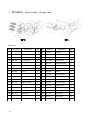
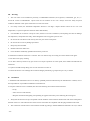
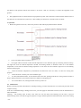
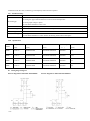
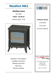
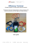
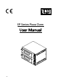
EP Series Pizza Oven
User Manual
1/6
Index
I
Machine illustration diagram
II
Part list
III
Warning
IV
Installation instruction
V
Operation instruction
VI
Maintenance
VII
Trouble shooting
VIII
Specification
IX
Electrical drawing
Please, read instruction before using the oven.
2/6
I EP2&EP1 Explode diagram
II. Part list
No.
Parts No.
Description
QTY
No.
Parts No.
Description
QTY
1
EP2-001
Cabinet
1
1
EP1-001
Cabinet
1
2
EP2-002
Cotton Board
2
2
EP1-002
Cotton Board
1
3
EP2-003
Cable
1
3
EP1-003
Cable
1
4
EP2-004
binding post
1
4
EP1-004
binding post
1
5
EP2-005
Halongen Lamp
1
5
EP1-005
Halongen Lamp
1
6
EP2-006
Side Board
1
6
EP1-006
Side Board
1
7
EP2-007
Thermostat
3
7
EP1-007
Thermostat
2
8
EP2-008
Switch
2
8
EP1-008
Switch
2
9
EP2-009
Operation Board
1
9
EP1-009
Operation Board
1
10
EP2-010
Knob Sit
3
10
EP1-010
Knob Sit
2
11
EP2-011
Knob
3
11
EP1-011
Knob
2
12
EP2-012
Indicator Light
3
12
EP1-012
Indicator Light
2
13
EP2-013
Rubber Feet
4
13
EP1-013
Rubber Feet
4
14
EP2-014
Door
2
14
EP1-014
Door
1
15
EP2-015
Heating Element
3
15
EP1-015
Heating Element
2
16
EP2-016
Side Board
1
16
EP1-016
Side Board
1
17
EP2-017
Pizza Stone
2
17
EP1-017
Pizza Stone
1
18
EP1-018
Handle
2
18
EP1-018
Handle
1
3/6
III. Warning:
1.
The oven must not be installed in proximity of inflammable materials (wood, plastics, combustible, gas, etc.). 2.
Avoid the contact of inflammable
objects with the hot surfaces of the oven. Always assure the safety fireproof
conditions. Maintain a free space around the oven of at least 50cm.
3.
For safety reasons, the maximum temperature allowed is 350 deg.C. despite thermo control can be over such
temperature ( as special required to install for tailor made feature).
4.
It is forbidden to use throws or drips of water, abrasive of corrosive substances, and anything else that can damage
the components, compromise the safety, and be dangerous from an hygienic point of view.
5.
Do not use the wet hand to touch the any switch or part on the switch panel.
6.
Do not use the oven if any damage part found.
7.
Keep away from chirlden.
8.
Read all instruction before use.
9.
Oven should be installed by qualified electrician by local law.
10. Maximum continuous work time is 12 hours. The oven must be stop for cooling for 3 hours before work again.
11. No direct water spray cleaning.
12. No direct touch by hand on any part of the oven expect operation on switch panel, door handle and staff ball for
exhaust air.
13. Operator should be keep taking care of oven when the oven turn on.
14. Check the electric wire breakage due to material fatigue periodically, eg. Inspection per every 3 months
IV.
Installation
1. Installation and maintenance have to be done by qualified personnel authorized by the manufacturer or dealer, who is
not responsible for any mistaken installation or manumission.
2. The place where the oven is installed, must have the following environment al characteristics:
- be dry.
- water sources at safe distance;
- adequate ventilation and lighting corresponding to hygiene and security rules following the existing law.
3.
Verify that the electrical set-up corresponds with the numbers of the technical characteristic and on the small plate at
the back of the oven. The characteristics of the electric socket must be compatible with the plug installed on the cable.
4. The connection with the electric network must be made by putting a suitable differential automatic cut-out, in which
4/6
the distance of the aperture between the contracts is at least of 3 mm. It is necessary to connect the equipment on the
ground.
5. The equipment must be connected with an equi-potential system. The connection is made with the terminal close to
the cable (the one which has this symbol on it). The bonding wire must have a minimal section of 10mm.
V Operation
1
Before the ignition of the oven, remove the protective film and all polyfoam inside the chamber.
2
Turn on the main switch to position “ 1”.
3
Turn upper and lower thermo control desired temperature. Power indicator light up for heating element working.
The light turn off if the desired temperature reached. The heating element is automatic switch on if the chamber
temperature is lower than the desired setting temperature. At the same time the indication light turn on if the heating
element working again.
4
Check the chamber temperature by thermometer for EP4/6/8/12 series. For EP2, it is timer for cooking alert
purposes.
5
Check the Pizza or food by turn on the chamber light.
6
For EP4, EP6 EP8 and EP12, in the left hand side of the door, pushing staff ball for closing exhaust window to
keep or pulling staff ball to open exhaust window for different cooking purposes.
7
VI
For switch off the oven, turning the main switch to position “0”.
Maintenance:
Before executing any kind of maintenance, including cleaning, you must disconnect the oven electrically and wait for the
complete cooling.
In the case of malfunctioning or damage of the oven, you must apply for authorized assistance, form the manufacturer or
authorized dealer.
Cleaning – The cleaning must be done every time the oven has been used following all the rules to provent
malfunctioning of the oven and for hygienic purposes. Using a suitable spatula and solft metal brush, remove the cooking
5/6
residues from the fire stone, which they go subsequently removed with a aspirator.
VII
Trouble shooting:
Trouble
Possible solution
○
1 .Check electrical wiring collectly connected.
No heating up
○
2 Setting the upper and bottom thermo control to desired temperature.
○
3 Wrong input voltage or phase.
○
4 Call authorized dealer if other case.
Electric shock
Stop using the oven and call authorized dealer for service
Chamber no light
Turn on the chamber of call authorized dealer to replace bulb.
Bad burning smell
Call authorized dealer to check electrical circuit.
Un-even cooking
Re-set upper and bottom thermo control
Or call authorized dealer to check whether the heating element burn and replace.
VIII
Specification
Temperature
Outside
Chamber dimension
Rated voltage
Rated Power
range
( mm )
( mm )
(
( kW )
EP1S
0~350 ℃
560X570X280
410X410X110X1PCS
220-240V
1.6
EP1P
0~350 ℃
560X570X280
410X410X110X1PCS
220-240V
21.6
EP2S
0~350 ℃
560X570X440
410X410X110X2PCS
220-240V
2.4
EP2P
0~350 ℃
560X570X440
410X410X110X2PCS
220-240V
2.4
Model
IX
dimension
Wiring diagram legend.
Eiectric diagram for 220V-240V EP2P&EP2S
6/6
V )
Eiectric diagram for 220V-240V EP1P&EP1S