1
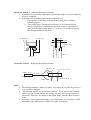
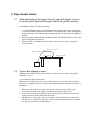
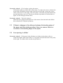
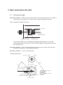
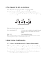
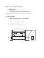
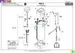
GEMINI Printer Trouble Shooting Procedures
1. Missing Dots
1.1
Dots do not come out
A. The front of the printer is slanting downwards.
B. Due to a gap in the bimorph actuator, the main pin is being pressed against the
front side.
C. Due to a failure in the seating plate, the main pin slides towards the front side.
D. The comb portion of the guide is warped
E. A timing gap
1.2
Excess dots come out
A. The front of the printer is slanting upwards.
B. There is damage or a dent in the seating plate and the main pin is not moving
smoothly.
C. The main pin can not be pushed out due to the transition time of the bimorph
actuator movement.
D. The comb portion of the guide is warped
E. A timing gap
F. There is damage or dirt on the base of the main pin.
Corrective Action 1 – Replacing a defective seat plate
1. Remove the screws on both sides of the plate and replace it.
2. Put the guide pins into the guide holes, adjust the position, and fasten the screws.
Corrective Action 2 – Repairing damage to the base of the main pin
1. Remove the pin which is misprinting.
2. Inspect the base of the main pin with a 10-power magnifying glass. If there are
any blemishes or abrasions, polish the base.
To erase scratches, rub off them with a sandpaper of No. 1000 then burnish with
a polisher.
Corrective Action 3 – If there is a bend in the shaft of pin guide (1)
1. Since the pin cannot move smoothly, straighten the bend.
Correction Action 4 – Adjusting the bimorph actuator
1. Techniques for performing adjustments with the adjusting tool (see the adjusting
tool user’s manual).
2. Techniques for performing adjustments without the tool
a. Face the base of the main pin towards the seating plate (reference
following figure).
b. Turn on the power. The main pin will move to its forward position.
Remove pin guide (2) and align the main pin so that it is positioned .5
mm below the face of main guide (1). (If there is very little movement,
the bimorph actuator is defective).
PinGuide(2)
PinGuide(1)
0.5mm
1.52mm
BasePlate
MainPin
MainPin
Corrective Action 5 – Replacing the bimorph actuator
ReaderLines
RubberPlate
InstallationScrew
Bimorph
BimorphHolder(2)
BimorphHolder(1)
ReaderLines
Notes:
•
•
•
The bimorph actuator is made of ceramic. Use caution if you place any stress on
it as it could be damaged.
The bimorph actuator is a piezoelectric material. If you increase the electrical
power even just a small amount, the voltage can cause the bimorph actuator to
bend itself. Therefore, to return it to the regular shape, short the three electrical
leads.
Since there can be significant changes over elapsed time, it is necessary to make
adjustments after 2000 usages. (Adjust if it begins to misprint.)
2. Paper feeder failure
2.1
If the positioning of the paper is faulty, gaps will appear, such as
in the line pitch, because the paper cannot be moved smoothly.
<Installation of paper for proper printing>
1. Avoid installing the printer on inherently instable places such as on weak tables
or on desks which are burdened with other overweight items. Faulty printing may
result if the front side of the printer is hanging down or if the printer is shaking or
slanted.
2. Place the paper underneath the installation stand. The ideal position is to have the
paper being pulled up and out.
3. Always be sure to install the printer stand so that it is level (use a carpenter’s
level to check).
BraillePrinter
BraillePaper
PrinterStand
2.2
Tractor belt slippage or wear
(Pulling unreasonably on the paper while it is entered into the feeder can produce
slippage or wear.)
<Concerning the paper and tractor>
When there is a large increase of force on the tractor, it can be the cause of tractor
belt wear or slippage. Please be careful of the following items whenever the paper is
pulled out:
1. Whenever you pull out the paper, always do it after you turn off the power.
Alternatively, remove the paper from the tractor and then pull it out.
2. If you turn off the power during printing, do not pull out the paper because the
printer pins may still be thrust onto the paper.
3. Should step 2 occur, turn on the power again, wait for about four seconds, turn
off the power, and pull out the paper. (The second time that the power is turned
on, the pins will retract from the paper).
Corrective Action 1 – If it is broken, replace the tractor.
Unfasten the pulleys on both sides of the tractor. To replace the tractor, unfasten the
tractor shaft, and pull the tractor either from left or from right. Loosen the screws,
either on the left or on the right, of the side plates. Extract the sub-shaft and tractor
upwards until they come out. The tractor can then be put back in. Put the belts on
again over the belt gaps on both sides.
Corrective Action 2 – The belt is slipped.
When the belt is slipped, take apart one of the tractors from the shaft and shift the
belt so that the 凸 is adjusted symmetry
2.3
If there is slippage in the distance between the leading edge of
the paper and the printing position, there is a sensor failure or
curvature in the leading edge of the paper
2.4
Line spacing is shifted
Corrective Action 3 – If the paper feeder fails due to a failure in the rubber roller; to
replace the rubber roller, take off the “E” ring on the left side and remove the pulley
on the right. The rubber roller can then be put back on.
3. Open holes before the dots
3.1
Dots are too high
Corrective Action 1 – When the main pin protrudes out too much (the dots are too high), or
if the paper will not advance, it is necessary to adjust the height of the dots.
<How to adjust the height of the dots>
Bearing
EccentricShaft
AdjustmentShaft
LockingScrew
Loosen the locking screw, while lightly striking the adjusting stem, if you turn
towards the direction of the arrow, the dots will be higher; in the opposite direction,
they will be lower.
Corrective Action 2 – If the slit in the Mylar board is sharp (scrap a little off of the edge
from the circumference of the Mylar board hole)
Corrective Action 3 – In case of wrong timing
<Timing adjustments>
EccentricShaft
Pulley
Belt
SlitPlate
45'
Pulley
SlitPlateOpening
PrintSensor
CenterShaft
CenterPulley
PinReturnCam
PinReturnCamShaft
DirectionMark
4. The shapes of the dots are malformed
4.1
The platen and pin guide plate are slipping a little
Corrective Action 1 – To adjust the installation position of the pin guide plate:
Loosen the four screws installed on the pin guide plate. Inspect how the pins are
entered into the pin guide holes. (Be careful that the pins do not fall out by loosening
the screws too much).
Normal
SlidForward
SlidBackward
PaperDirectionFlow
High voltage (bimorph actuator return voltage)
Low…approximately 125V
Test Voltage (use for safely checking that the bimorph
actuator will move a small amount with a lowered
voltage)
High…220V
Voltage for normal movement
When you want to verify the voltage, use a tester to check that both ends of the condenser
on the bimorph actuator driver circuit board have 340V 10 ma.
5. Weak Printing of Ink Characters
5.1
Failure of the ink ribbon cassette (Change a ribbon cassette)
5.2
Ink printer head dirt staining the paper (such as horizontal lines)
Corrective Action 1 – If there are waste particles or dust on the head, unfasten the head and
remove the material with something like a toothbrush.
Corrective Action 2 – If nothing is printing (neither ink nor Braille) even though printer
data is input, the data is not being entered correctly.
6. Halts in the Middle of Printing
6.1
Faulty sensor
6.2
The sensor and paper are not making contact
Corrective Action 1 – Verify the sensor installation and the sensor lever.
7. Print part unit
7.1
How to remove bimorph unit from the body
1. Remove the Braille Print part unit
2. Pull out the 4 screws on the side-A
A: 8mm screws which equips bimorph unit
3. Pull put 2 guide pins
4. Remove bimorph unit from Print part unit
PlateParts
GuidePins
Platen
A:Screws
A:Screws