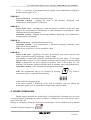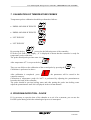
1
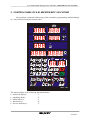
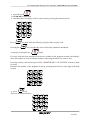
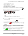
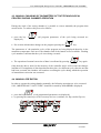
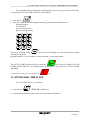
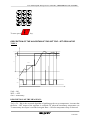
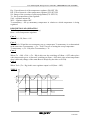
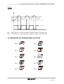
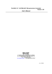
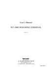
User manual of the microprocessor controller „MIKSTER MCC 106 FUTURE” R Sp. z o.o. 41-250 Czeladź, ul. Wojkowicka 21, Poland Tel. +48 (32) 266-76-41; 265-70-97; 763-77-77 Fax: 763-75-94 www.mikster.com [email protected] (21.06.2004) User manual of the microprocessor controller „MIKSTER MCC 106 FUTURE” CONTENT Page TECHNICAL DATA:............................................................................................................................................3 1. APPLICATION.................................................................................................................................................3 2. CONTROL PANEL OF S.M. MIKSTER MCC 106 FUTURE ..........................................................................4 3. SECURITY CODE............................................................................................................................................5 4. STARTING THE WORK OF S.M. „MIKSTER MCC 106 FUTURE” ...............................................................5 4.1. PROGRAMMING TECHNOLOGICAL PROCESSES ..............................................................................5 4.2 STARTING OF EXECUTION OF A TECHNOLOGICAL PROGRAM USING S.M. „MIKSTER MCC 106 FUTURE” .......................................................................................................................................7 4.2.1. MODE OF PROGRAM EXECUTION...........................................................................................................8 4.3. MANUAL CHANGING OF PARAMETERS OF THE TECHNOLOGICAL PROCESS DURING CHAMBER OPERATION ................................................................................................................................9 4.4. MANUAL OPE RATION...........................................................................................................................9 5. SIGNALLING OF ERRORS AND BRAKES DOWN .......................................................................................10 LIST OF ERRORS SIGNALLED....................................................................................................................10 6. SOUND SIGNALLING ...................................................................................................................................11 7. CALIBRATION OF TEMPERATURE PROBES.............................................................................................12 8. PROGRAM EXECUTION - PAUSE ...............................................................................................................12 9. COMPLETING WORK OF THE CHAMBER.................................................................................................13 10. ADJUSTMENT THE TEMPERATURE GROVE ∆ ......................................................................................13 11. REACTION TO EXCEEDING TEMPERATURE RANGE............................................................................13 12. TIMER START OF THE AUTO START PROGRAM.....................................................................................13 13. SETTING REAL TIME CLOCK....................................................................................................................14 DESCRIPTION OF THE ALGORITHM OF TWO SET FOR - SET REGULATOR ............................................15 14. DEFINITION OF TRANSDUCERS OUTPUTS ...........................................................................................17 R -2- 21.06.2004 User manual of the microprocessor controller „MIKSTER MCC 106 FUTURE” TECHNICAL DATA: POWER SUPPLY: ~ 24V (AC), TRANSFORMER 220-24V PROVIDED DESIGNED: ONE MODELLED, TYPE „FRONT PANEL” OUTPUTS: • 8 or 10 TRANSDUCER OUTPUTS (SHORT CIRCUIT) 250V, Σ CURRENT OF TRANSDUCERS CONNECTED Icmax = 4A • RS PORT (232 OR 485) FOR COMMUNICATION WITH THE CONTROLLER COMPUTER INPUTS: • 2 MEASUREMENT CHANNELS, TEMPERATURE PROBE PT-100 (PT-500) MEASURING RANGE -20OC TO +400 OC, RESOLUTION 0.1 OC • BINARY CONTROL INPUT -220V AC 1. APPLICATION The basic functions of S.M. MIKSTER MCC 106 FUTURE are: • • • • • measuring of the temperature of the chamber measuring of the temperature of the batton control of 8 (optionally 10) actuators analysis and signalling brake down statuses automatic execution of work program The MCC 106 FUTURE controller is capable of programming a maximum of 50 technological programs which may be freely adapted by the user. R -3- 21.06.2004 User manual of the microprocessor controller „MIKSTER MCC 106 FUTURE” 2. CONTROL PANEL OF S.M. MIKSTER MCC 106 FUTURE All operations connected with start up of the controller, programming, manual changes etc. Are performed using the control panel. WRIT TEN READ % 11 12 1 2 10 9 3 8 4 7 6 5 h:min ? ? MCC - 106 The panel consists of the following functional blocks: • numerical displays -1• signalling diodes -2• numerical keys -3• function keys -4• devices status keys -5- R -4- 21.06.2004 User manual of the microprocessor controller „MIKSTER MCC 106 FUTURE” All information concerning the status of the controller S.M. „MIKSTER MCC 106 FUTURE” at work (work status, values of parameters programmed and red, signalling on / off devices) are displayed by numerical displays and diodes. If a particular device is working or a particular function is active, the diode lit contiuesly blinking diodes signal temporary or brake down status. Introducing data to the memory of S.M. „MIKSTER MCC 106 FUTURE” data correction, recalling the particular functions of the controller is performed by pressing suitable function keys, numerical keys and device status keys. 3. SECURITY CODE In order to protect data stored in the memory of S.M. „MIKSTER MCC 106 FUTURE” from unauthorised access a security code was introduced. The code must be given when we want to introduce changes in data concerning technological programs (detail description item 4.1). The security code is set by the service of the curing chamber. The default values are 222 222. 4. STARTING THE WORK OF S.M. „MIKSTER MCC 106 FUTURE” After power supply switched on the displays of the controller, display TEST for about 5 seconds and then STOP, which signals correct operation of the system. At that moment it is possible to start the following functions of S.M. „MIKSTER MCC 106 FUTURE”: • programming technological processes (programming mode), • setting up fixed parameters (set up mode), • manual mode, • starting up a program executed by S.M. „MIKSTER MCC 106 FUTURE” (automatic work mode). 4.1. PROGRAMMING TECHNOLOGICAL PROCESSES In S.M. „MIKSTER MCC 106 FUTURE” the user may programme up to 49 technological programs (1-49). Each program consists of 10 (20) cycles with the possibility of programming them at the users option. The programming amount to storing the required data (chamber temperature, batton temperature, humidity etc.) by performing a serious of programming cycles. Switching S.M. „MIKSTER MCC 106 FUTURE” into the programming mode: R -5- 21.06.2004 User manual of the microprocessor controller „MIKSTER MCC 106 FUTURE” • press the key (code 000 000 is displayed) • introduce three first digits of the security code by pressing the numerical keys. Press Pressing the key then enter the following 3 digits of the security code. key switches the active field of the parameter introduced. Accept by pressing the key again. If correct code has been introduced, the device switches in the program in mode, the displays show the number of cycle 00 and the number of the program which we want to store. If wrong security code has been given S.M. „MIKSTER MCC 106 FUTURE” returns to stand by mode. Introduce the number of the program 00-49 by pressing numerical keys (the digits will blink in turn) key, • press Then use the numerical keys R -6- 21.06.2004 User manual of the microprocessor controller „MIKSTER MCC 106 FUTURE” to store in turn: • CHAMBER TEMPERATURE [DEG C] • BATTON TEMPERATURE [DEG C] • TEMPERATURE GROVE (∆ ) [DEG C / min] • RELATIVE HUMIDITY [%] • CYCLE EXECUTION TIME [hours, minutes] If acceptable range of values being introduced is exceeded, 0 will be stored and the operation is repeated. Also if the user attempt to enter two many digits, storing that field starts again. After correct values have been introduced, move to the next data field by pressing . While storing a technological program it’ s necessary to define the status of executory devices (executory device ON/OFF). This is done by pressing device status keys. • After parameters of a particular complete cycle are stored and find correct, press key and device will be ready for programming another cycle. By pressing the key, the users moves to the next cycle 00-09(19); after cycle 9(19) follows the cycle 00. • To move to programming the next program, press key. • After all the cycles have been programmed to complete operation and store the data in memory press the key is displayed. . The controller switches into stand by mode and STOP 4.2 STARTING OF EXECUTION OF A TECHNOLOGICAL PROGRAM USING S.M. „MIKSTER MCC 106 FUTUTRE” An automatic cycle (start up of the chamber) may take place if S.M. „MIKSTER MCC 106 FUTURE” is in stand by mode (STOP is displayed) in order to do that act as follows: • press key - READY is displayed, program number field blinks. • introduce the number of the program with numerical keys and then the number of the cycle from which execution of the program will begin. R -7- 21.06.2004 User manual of the microprocessor controller „MIKSTER MCC 106 FUTURE” Change the field by pressing (the start up progress may be stopped by pressing STOP key, S.M. „MIKSTER MCC 106 FUTURE” will then return to stand by mode and STOP will be displayed.) After program number has been entered correctly, confirm by pressing The chamber starts operation 4.2.1. MODE OF PROGRAM EXECUTION By starting a program, S.M. „MIKSTER MCC 106 FUTURE” will control executory devices based on the parameters which has been programmed and checking program execution conditions and timing. For S.M. „MIKSTER MCC 106 FUTURE” complete a cycle, the following conditions must be made: Example 1 (Batton temperature programmed more than 0; cycle time programmed more than 0) cycle will be completed when: • batton temperature read out is more than or equal batton temperature programmed or • cycle time read out is more than or equal cycle time programmed Example 2 (Batton temperature programmed more than 0; cycle time programmed = 0) cycle will be completed when: • batton temperature read out is more than or equal batton temperature programmed Example 3 (Batton temperature programmed = 0; cycle time programmed more than 0) cycle will be completed when: • cycle time read out is more than or equal cycle time programmed Chamber operation will be completed after all cycles of the program have been executed. If we want a particular cycle to be excluded, we should programme both • batton temperature programmed = 0 • cycle time programmed = 0 R -8- 21.06.2004 User manual of the microprocessor controller „MIKSTER MCC 106 FUTURE” 4.3. MANUAL CHANGING OF PARAMETERS OF THE TECHNOLOGICAL PROCESS DURING CHAMBER OPERATION During the work of the curing chamber it’s possible to correct manually the program data stored earlier. To achieve this proceed as follows: • press the key displayed), (all peogram parameters of the cycle being executed are • like in item 4.1 introduce changes in the program pressing the key. The parameters of the particular cycles of the program are being displayed therefore in the meantime temperature read out of the chamber and of the batton are not available. Fleshing cycle numbers confirms that the cycle is not being executed. • The operation of manual correction of data is confirmed by pressing key again. Only then the data is stored in the memory of the controller and it will execute the changes introduced. If completion of data introduction takes place in a different cycle, then do one that had been executed, the chamber will continue executing the cycle during which the operation of manual data correction was executed. 4.4. MANUAL OPE RATION In order to operate the curing chamber manually, the following operation are to be executed: S.M. „MIKSTER MCC 106 FUTURE” should be in stand by mode STOP is displayed. • press the key (0-ed programmed parameters are displayed) • by pressing the status keys of the executory devices (ventilator, air flap, smoke flap etc.) R -9- 21.06.2004 User manual of the microprocessor controller „MIKSTER MCC 106 FUTURE” • set the devices, which are to start up after the key is pressed (devices which were set for switching on signal by blinking diode). • Following item 4.1 set up the parameters of the process executed. The chamber will start operating and the devices will be steered as required after the key is pressed. Conditions of completing program in manual mode like in item 4.2.1. During execution of the manual program, the executory devices of the curing chamber may be switched ON and OFF at the users option. key. The automatic mode program is stopped after pressing the To continue an interrupted program press key. • Leaving manual mode will take place after the key is pressed again. 5. SIGNALLING OF ERRORS AND BRAKES DOWN In case of break down status during the work of S.M. „MIKSTER MCC 106 FUTURE” the execution of the program is interrupted and word ERROR plus error’s number are displayed; sound signal is also generated. The signal may be switched off by pressing the key , the After removing the reason of fault to return in standby mode press key controller starts work from the moment at which the program had been interrupted by press key LIST OF ERRORS SIGNALLED ERROR 17 Cause of the error - control input error signalled Controller reaction - depending on F12 (SET UP) If F12 = 0 - error 17 control is switched of If F12 = 1 - the chamber will continue working, error communicate is repeatedly displayed and the warning signal is on. R -10- 21.06.2004 User manual of the microprocessor controller „MIKSTER MCC 106 FUTURE” If F12 = 2 - execution of the program will be stopped, error communicate is displayed and the warning signal is on. ERROR 21 Cause of the error - exceeding temperature range Controller reaction - stopping the work of the chamber, displaying error communicate, warning signal is generated. ERROR 25 Cause of the error - attempting to switch on both the ventilators at the same time while in the set up functions F4 blockade of such simultaneous switching on of both ventilators had been programmed Controller reaction - stopping work of the chamber, displaying error communicate, warning signal is generated ERROR 30 Cause of the error - signalling RAM control sum Controller reaction - error communicate is displayed repeatedly, automatic work mode can not be switched on. N.B.! In case of this error, service should be called. ERROR 40 Cause of the error - signalling of a brake in automatic work mode, manual work mode or autostart caused by temporary a lack of supply. After supply re-emerges the controller checks the time of power supply . If it’s longer than the value set up in F11, the controller will stop work and return to stand by mode STOP is displayed if the power supply break down. Time is shorter then F11, the controller will continue operation from the point at which the power supply had failed. Controller reaction - error communicate is displayed repeatedly. N.B.! The communicate may be set (cleared) by pressing temperature probes is signalled by displaying key. Fault to in the field of the damaged probe. If the above symbol is displayed in the field of humidity read out, whiled dry temperature probe is ok. it means that wet temperature probe is faulty. 6. SOUND SIGNALLING During normal operation the sound signal is switched while switching on to the next cycle and after the technological process execution is completed is set by the service and is stored in the SET UP. During an emergency (fault) the interrupted sound signal will be sounded until its manual switched off by pressing the key . R -11- 21.06.2004 User manual of the microprocessor controller „MIKSTER MCC 106 FUTURE” 7. CALIBRATION OF TEMPERATURE PROBES Temperature probes calibration should be performed as follows: • PRESS AND HOLD THE KEY • PRESS AND HOLD THE KEY • LET THE KEY • LET THE KEY By pressing the key proceed to the following tests of the controller. If in the cycle field of the display, „0” is displayed it means that the controller is ready for temperature probe calibration. The probe should probe put into water ice mix. After temperature 0oC is set press the key 2 . Then you can follow to the calibration of the second probe by pressing the Calibration is performed as above. key. After calibration is completed press , the parameters will be stored in the controller memory. Calibration of temperature probe for 100oC is performed by adjusting the potentiometers located at the back of the controller. The probe should be put into boiling water and after putting the probe into boiling water adjust the potentiometer until 100 is displayed in the relevant channel. 8. PROGRAM EXECUTION - PAUSE If it’s necessary to open the door of the chamber or to air it for a moment, you can use the PAUSE option during which the technological process is interrupted. R -12- 21.06.2004 User manual of the microprocessor controller „MIKSTER MCC 106 FUTURE” The PAUSE mode can be switched on if the S.M. „MIKSTER MCC 106 FUTURE” is during the execution of an automatic cycle. It is performed by pressing the will be displayed). Ending the PAUSE is performed by pressing the by service. key. (PAUSE key again or after a time set up 9. COMPLETING WORK OF THE CHAMBER To stop the automatic process press the key. 10. ADJUSTMENT THE TEMPERATURE GROVE ∆ S.M. „MIKSTER MCC 106 FUTURE” has the possibility of adjusting temperature grove as in the function of time (fish curing technology) or in the function of batton temperature (burning / par boiling in temperature difference). During storing a technological program in the field over ∆ inscription, enter the value of temperature grove in oC/min or the difference the temperatures between the temperature of the chamber and the temperature of the batton. If 0 value of the ∆ is introduced, the function of the temperature grove is not executed. Manner of execution of the algorithm of temperature grove adjustment is defined in function F22 SET UP. Value of the function F21 SET UP 0 - ∆ off, 1 - ∆ in the function of time, 2 - ∆ in the function batton temperature. 11. REACTION TO EXCEEDING TEMPERATURE RANGE The controller react to temperature limit being exceeded after which ERROR 21 is signalled. The temperature range is determined by the function F29 SET UP, in this function the value is stored by which the temperature may exceed the programmed value. For example: IF THE PROGRAMMED VALUE IN THAT MOMENT IS 60OC AND THE VALUE OF FUNCTION F29 IS 10OC, THE ERROR WILL BE SIGNALLED IF THE TEMPERATURE READ OUT EXCEED 70OC. 12. TIMER START OF THE AUTO START PROGRAM R -13- 21.06.2004 User manual of the microprocessor controller „MIKSTER MCC 106 FUTURE” The controller allows starting the technological process at any given time of the day. To perform the AUTO START function, act as follows: , • press the key • enter the values of the following parameters by pressing the numerical keys: program number, cycle number, process start up hour, process start up minute, Successive pressing of the key results in switching on to the next parameter being entered in a sequence: program number ⇒ cycle number ⇒ auto start hour ⇒ auto start minute The AUTO START function will be on after the key is pressed. Diodes in AUTO START and START keys are blinking and a green diode is on on the keys AUTO START and STOP. To interrupt the setting up AUTO START press key. 13. SETTING REAL TIME CLOCK To set real time clock, act as follows: • press the key . SET CLO is displayed. • by pressing the numerical keys enter the current hour and minute. R -14- 21.06.2004 User manual of the microprocessor controller „MIKSTER MCC 106 FUTURE” To store press key. DESCRIPTION OF THE ALGORITHM OF TWO SET FOR - SET REGULATOR TYPE 1 Hg Tz Hd Zd Tzchwi ZA£ WY£ ZAŁ = ON WYL = OFF chwi = momentary DESCRIPTION OF THE MEANINGS: Tod < (Tz - Hd) is the executed algorithm of pushing up the set up temperature, it means that the Rout = OFF output of the regulator is switched off when the momentary temperature set Tz momentary the output is switched on again Rout = ON after temperature drop is detected. R -15- 21.06.2004 User manual of the microprocessor controller „MIKSTER MCC 106 FUTURE” Hg - Upper histeresis of the temperature regulator (F26 SET UP) Hd - Lower histeresis of the temperature regulator (F25 SET UP) Zd - Range of the operation of push up algorithm (F23 SET UP) Tz - Set up temperature of the regulator ZA£ - regulator output ON WY£ - regulator output OFF Tz momentary - Set up momentary temperature in relation to which temperature is being regulated. DESCRIPTION OF OPERATING Tod - Temperature read out (momentary) Rout - exit of temperature regulator Case 1 When Tod < Zd, Rout = ON Case 2 When Tod ≥ Zd and the new momentary set up temperature Tz momentary is set determined at the same time Tz momentary = (Tz - Tod)/2. In case of setting the set up temperature Tz momentary ≥ (Tz - Hd), then Tz momentary = Tz Case 3 When (Tz + Hd) ≥ Tod > (Tz - Hd) in this case the switching off (Rout = OFF) takes place when temperature grove is detected; switching on (Rout = ON) takes place when temperature drop is detected (change of the status Rout is delayed by the time set in F24). Case 4 When Tod > (Tz + Hg) in this case regulator output is off (Rout = OFF). TYPE 2 Hg1 Hd1 Tz ZA£ WY£ R -16- 21.06.2004 User manual of the microprocessor controller „MIKSTER MCC 106 FUTURE” TYPE 3 Hg1 Hd1 Tz ZA£ WY£ Hg 1 - Upper histeresis of the temperature regulator channel 2 (F28 SET UP) Hd 1 - Lower histeresis of the temperature regulator channel 2 (F27 SET UP) 14. DEFINITION OF TRANSDUCERS OUTPUTS RE0 - RE1 - RE2 - RE3 - RE4 - RE5 - RE6 - RE7 - RE8 - RE9 - . R -17- 21.06.2004