1
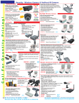
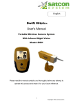
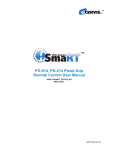
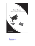
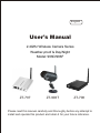
English
User's Manual
2.4GHz Wireless Camera Series
Weather-proof & Day/Night
Model: 906D/906F
ZT-707
ZT-906T
ZT-708
Please read this manual carefully and thoroughly before any attempt to
install and operate this product and retain it for your future reference.
TABLE OF CONTENTS
INTRODUCTION
Notice
Approval Information (FCC/CE)
Restrictions
Maintenance
PRODUCT
Package Contents
Feature Locations
Adapter
1~3
1
1~2
3
3
4~6
4
5
6
INSTALLATION & USAGE
7~12
Installation
Camera Channel Setup
Receiver Mode Setup
Night Vision
7~9
10
11~12
12
SPECIFICATIONS
TROUBLESHOOTING
EU Environmental Protection
Waste electrical products should not be disposed of with
household waste. Please recycle where facilities exist.
Check with your Local Authority or retailer for recycling
advice.
13
14
INTRODUCTION
Thank you for purchasing this wireless camera kit. This product works
at ISM-2.4GHz frequency band, which could be legally used worldwide
without permission. We feel confident that you will be pleased with the
quality and features of this product.
The camera features one CCD image sensor and a transmitting module
to capture the image and transmit them wirelessly.
The receiver features a receiving module to receive and output AV
signals.
Notice
Notice: This product may cause interferences with other wireless
equipment that operates at 2.4GHz ISM band. Please turn off one of
the equipments to eliminate the interference.
Product Assurance: This camera will emit electromagnetic wave,
just like other wireless products. But its transmitting power is less than
other wireless products such as mobile phones. The 2.4GHz wireless
camera meets wireless frequency security standards and recommended
indexes while working. These standards and indexes are certificated by
academic organization and represent the cogitative research of the
scientific workers who continuously explore and annotate the involved
fields. So we believe that our products are safe for customers.
Approval Information
All our products meet the requirements of approval FCC or CE, and
are granted the FCC or CE certification. They are authorized to bear
FCC or CE mark.
1
FCC
This equipment has been tested and found to comply with the limits for
a Class B digital device, pursuant to Part 15 of the FCC rules. These
limits are designed to provide reasonable protection against harmful
interference in a residential installation. This equipment generates,
uses and can radiate radio frequency energy and, if not installed or
used according to the instructions, may cause harmful interference to
radio communications. However, there is no guarantee that interference
will not occur in a particular installation. If this equipment does cause
harmful interference to radio or television reception, which can be
determined by turning the equipment off and on, the user is encouraged
to try to correct the interference by following measures:
-Reorient or relocate the receiving antenna.
-Increase the separation between the equipment and the receiver.
-Connect the equipment into an outlet on a circuit different from that to
which the receiver is connected.
-Consult the dealer or an experienced radio/TV technician for help.
This device complies with Part 15 of the FCC Rules. Operation is
subject to the following two conditions:
(1) This device may not cause harmful interference, and
(2) this device must accept any interference received, including
interference that may cause undesired operation Changes and
modification not expressly approved by the manufacturer or
registrant of this equipment can void your authority to operate this
equipment under Federal Communications Commissions rules.
CE
This product complies with standards including Low Voltage Device
Directive 73/23/EEC; EMC Directive 89/336/EEC and R&TTE Directive
1999/5/EC. It passed the subject tests by the authority concerned and
is authorized to bear CE mark.
2
Restrictions
1. DO NOT use this product to violate one's privacy. Monitoring one's
activities without consent is illegal and this product is not designed
and manufactured for such purpose;
2. DO NOT put this product near any medical equipment. Radio
waves might potentially cause breakdown of electrical medical
equipment. So this product should be placed at least 1 feet away
from any heart pacemaker. Radio waves might potentially
influence heart pacemaker and lead to respiratory disturbance;
3. DO NOT use this product for any illegal activities. We shall not be
responsible for any consequences of illegal acts committed by the
user.
Maintenance
1.
2.
3.
4.
5.
Ensure the sufficient ventilation space is available;
Do not shake or strike the product;
Keep it dry and dustless and avoid exposing it to direct sunlight;
Do not place product near any magnetic objects;
Avoid putting the product in places where the constantly changed
temperature or humidity occurs;
6. Keep product away from heat sources such as electric heater;
7. Do not use the camera near aggressive chemicals;
8. Do not use the camera in the places which are enclosed by metal.
The surrounding metal like lifter, cabin, may shield the
electromagnetic wave, and result in failure of signal reception;
9. Please obey the local government's environment protection policy;
10. Please turn off the power when left unused;
11. Do not disassemble or repair the camera or receiver; doing so
might cause damages to the product.
3
PRODUCT
Package Contents
This package comes with the following items. Please check whether
they are all included in the packaging box, if one or some is missing,
contact the retailer for replacement.
① 2.4GHz Wireless Camera×1
② Bracket for Camera×1
③ 2.4GHz Wireless Receiver×1
3
2
1
④ Antenna ×2
⑤ Adapter for Camera×1
⑥ Adapter for Receiver ×1
4
⑦ AV Cable ×1
5
7
6
⑧ Channel Pick for Camera ×1
⑨ Mounting Hardware ×1
⑩ User's Manual ×1
⑨
10
906D means ZT-906T + ZT-707
906F means ZT-906T + ZT-708
Receiver Series
Note:
The pictures may vary from the actual objects.
ZT-707
4
ZT-708
Feature Locations
1. Camera
Antenna
Infrared Lights
Hood
Lens
Channel Switch
Universal Bracket
2. Receiver
ZT-707
Antenna
Power Socket
Power Switch
Channel Button
Channel Indicator
ZT-708
Antenna
Channel Button
Channel Indicator
Mode Control
Power Socket
AV Output
5
AV Output
Adapter
This product always conforms to the authenticated AC adapter. The
adapter should be marked one of the following:
UL Mark
SAA Mark
American power
supply authentication
Australia power
supply authentication
CE Mark
PSE Mark
European Union power
supply authentication
Japan power
supply authentication
GS Mark
CCC Mark
German power
supply authentication
China power
supply authentication
Note:
When using the power adapter, make sure the rating voltage on it is compatible
with that of the device to avoid potential damages resulting from incorrect usage
of power supply.
6
INSTALLATION & USAGE
Installation
1. Load the universal bracket to the camera as the following diagram.
To the bottom of camera
To the back of camera (optionally)
2. Connect the antenna to the camera.
3. Locate the camera to a specific position and then adjust it to a suitable
angle.
7
4. Connect the adapter (DC 12V 500mA) to the camera.
5. Connect the antenna to the receiver.
6. Connect the receiver to a monitor/TV with AV cable (yellow for video
and red for audio).
7. Connect the adapter (DC 8V 200mA) to the receiver and the channel
indicator lights up (only suitable for ZT-708).
8
Connect the adapter (DC 12V 300mA) to the receiver and push the
power switch to ON position and the channel indicator lights up(only
suitable for ZT-707).
8. Power on the monitor/TV and select AV mode.
9. Set the channel of receiver same as that of camera by pressing the
channel button continuously, and the pictures are displayed on the
monitor/TV.
ZT-707
ZT-708
10. Adjust the brightness, contrast and color of the monitor/TV for the
perfect effect.
9
Camera Channel Setup
You could adjust the channel switch to set the channel of camera for
multi-camera working or avoiding the interference. The steps are as the
following.
1. Pull out the hood as the shown direction.
2. Remove the front cover counter-clockwise.
3. Find out the channel switch close to the IR lights and adjust the
channel by channel pick.
Channel
Switch
4. Adjust the channel switch as the following diagram.
Channel Frequency
Channel Switch Setup Diagram
CH1=2,414MHz;
CH2=2,432MHz;
CH3=2,450MHz;
CH4=2,468MHz
10
Receiver Mode Setup(Only suitable for ZT-708)
The receiver can support up to 4 cameras working at the same time.
You are allowed to set the Mode Control as described below. The
Mode Control has the precedence over other buttons.
OFF
ON
M
L
Default Setting
Channel Set
OFF
ON
M
L
1
ON: CH1 Enable (Default)
OFF: CH1 Disable
2
ON: CH2 Enable (Default)
OFF: CH2 Disable
3
ON: CH3 Enable (Default)
OFF: CH3 Disable
4
ON: CH4 Enable (Default)
OFF: CH4 Disable
You can confirm which channel is set to receive signal from corresponding camera. With this function, you could set the unused channels to
OFF, so that they will be skipped during the Manual mode or Channel
Scan mode.
Channel-scan Set
OFF
ON
M
L
M: Manual Mode (Default)
L: Channel-scan Mode
11
1. Manual mode: Slide Mode Control switch to M to enter Manual
mode. In this mode, the receiver channel won't change until you
press the Channel Select Button.
Channel Select Button
2. Channel Scan mode: Slide Mode Control switch to L to enter
channel scan mode. In this mode, all the available channels will
display one by one looping in turn per 5s. So you can watch the
situations from up to 4 different cameras via one receiver.
Notes:
Press the Channel Select Button at the channel scan mode, the current
channel will be looped to the next one immediately.
Slide the Mode Control switch to M to exit the channel-scan mode.
Night Vision
The built-in IR lights in camera provide 15m range night vision for 24hrs
surveillance. The Infra-red lights will be automatically activated at night
or in dark places. The picture will turn Black & White (monochrome) in
Night Vision situation.
Built-in IR lights for about
15m Night Vision Range
12
SPECIFICATIONS
Items
Imaging Sensor
906F
512 x 582(PAL)
512 x 492(NTSC)
CAMERA
Total Pixels
RECEIVER
906D
1/4-inch Sharp CCD
39 o
0Lux
ISM 2,400MHz~2,483MHz
10mW/CE; 2mW/FCC
FM
18MHz
+12VDC
View Angle
Minimum Illumination
Transmission Frequency
Transmission Power
Modulation Type
Bandwidth
Power Supply
Consumption Current
120mA (IR OFF)
270mA (IR ON)
Unobstructed Effective
Range
100m
Night Vision Range
Dimensions
(W x D x H) (mm)
Weight
Receiving Frequency
Intermediate Frequency
Demodulation Type
Antenna
Receiving Sensitivity
Video Output Level
Audio Output Level
Power Supply
Consumption Current
Dimensions
(W x D x H)(mm)
(Excluding antenna )
Weight
Operating Temperature
Storage Temperature
Operating Humidity
15m
61 x 90 x 138
300g
ISM 2,400MHz~2,483MHz
480MHz
FM
50ohm SMA
≤ -85dBm
1Vp-p@75ohm, S/N>38dB
1Vp-p@600ohm
+8VDC
+12VDC
180mA
250mA
68 x 78 x 16
78 x 92 x 23
120g
184g
-10 oC~+50 oC/+14 oF~+122 oF
-30 oC~+85 oC/-22 oF~+185 oF
85%RH
* All the specifications are subject to minor change without prior notice.
13
TROUBLESHOOTING
When you experience the operation problems, please check and try
the following yourself before claiming that it is the defective product
or consulting the experienced technician.
Abnormal Phenomena
No image
No sound
Possible Reasons/Solutions
Check whether the camera/receiver
is connected to power supply and
powered on.
1. Check if the channel of receiver is
the same as that of camera;
Snowflakes
on image
Noisy
2. Check the distance & blocks.
1. Interfered with other devices;
2. Check the distance & blocks.
Ghost image
Normal sound
Mismatching the TV system of PAL
or NTSC.
No color
Normal sound
Interfered with other devices nearby;
Remove or turn off such devices.
Normal image
Noisy
S-M906G190011