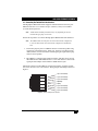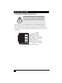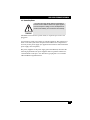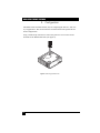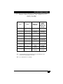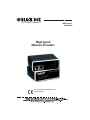
1
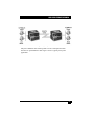
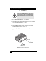
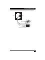
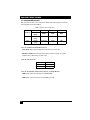
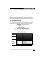
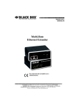
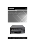
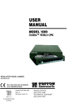
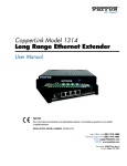
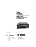
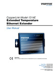
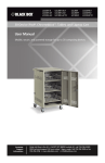
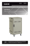
MARCH 2011
LB400A-R2
High Speed
Ethernet Extender
This is a Class A device and is not intended for use in a
residential environment.
HIGH SPEED ETHERNET EXTENDER
CE NOTICE
The CE symbol on your Black Box equipment indicates that it is in compliance
with the Electromagnetic Compatibility (EMC) directive and the Low Voltage
Directive (LVD) of the European Union (EU). A Certificate of Compliance is
available by contacting Technical Support.
RADIO AND TV INTERFERENCE
This device generates and uses radio frequency energy, and if not installed and
used properly-that is, in strict accordance with the manufacturer’s instructionsmay cause interference to radio and television reception. The device has been
tested and found to comply with the limits for a Class A computing device in
accordance with specifications in Subpart B of Part 15 of FCC rules, which are
designed to provide reasonable protection from such interference in a commercial installation. However, there is no guarantee that interference will not occur in
a particular installation. If the device does cause interference to radio or television reception, which can be determined by disconnecting the unit, the user is
encouraged to try to correct the interference by one or more of the following
measures: moving the computing equipment away from the receiver, re-orienting
the receiving antenna and/or plugging the receiving equipment into a different
AC outlet (such that the computing equipment and receiver are on different
branches).
Theis device is NOT intended nor approved to be connected to the PSTN. It is intended only for connection to
customer premise equipment.
WARNING
2
HIGH SPEED ETHERNET EXTENDER
This device contains no user serviceable parts. This
device can only be repaired by qualified service personnel.
• Do not open the device when the power cord is connected. For systems without a power switch and without
an external power adapter, line voltages are present
within the device when the power cord is connected.
• For devices with an external power adapter, the power
adapter shall be a listed Limited Power Source. The
mains outlet that is utilized to power the device shall be
within 10 feet (3 meters) of the device, shall be easily
accessible, and protected by a circuit breaker in compliance with local regulatory requirements.
• For AC powered devices, ensure that the power cable
used meets all applicable standards for the country in
which it is to be installed.
WARNING
• For AC powered devices which have 3 conductor
power plugs (L1, L2 & GND or Hot, Neutral &
Safety/Protective Ground), the wall outlet (or socket)
must have an earth ground.
• For DC powered devices, ensure that the interconnecting cables are rated for proper voltage, current, anticipated temperature, flammability, and mechanical
serviceability.
• WAN, LAN & PSTN ports (connections) may have hazardous voltages present regardless of whether the
device is powered ON or OFF. PSTN relates to interfaces such as telephone lines, FXS, FXO, DSL, xDSL,
T1, E1, ISDN, Voice, etc. These are known as “hazardous network voltages” and to avoid electric shock use
caution when working near these ports. When disconnecting cables for these ports, detach the far end connection first.
• Do not work on the device or connect or disconnect
cables during periods of lightning activity.
3
HIGH SPEED ETHERNET EXTENDER
In accordance with the requirements of council directive 2002/96/EC on Waste of Electrical and Electronic
Equipment (WEEE), ensure that at end-of-life you separate this product from other waste and scrap and deliver
to the WEEE collection system in your country for recycling.
Electrostatic Discharge (ESD) can damage equipment
and impair electrical circuitry. It occurs when electronic
printed circuit cards are improperly handled and can
result in complete or intermittent failures. Do the following to prevent ESD:
• Always follow ESD prevention procedures when
removing and replacing cards.
WARNING
• Wear an ESD-preventive wrist strap, ensuring that it
makes good skin contact. Connect the clip to an
unpainted surface of the chassis frame to safely channel unwanted ESD voltages to ground.
• To properly guard against ESD damage and shocks,
the wrist strap and cord must operate effectively. If no
wrist strap is available, ground yourself by touching the
metal part of the chassis
TRADEMARKS USED IN THIS MANUAL
All applied-for and registered trademarks are the property of their respective owners.
NORMAS OFICIALES MEXICANAS (NOM) ELECTRICAL SAFETY STATEMENT
Instrucciones De Seguridad
1. Todas las instrucciones de seguridad y operación deberán ser leídas antes
de que el aparato eléctrico sea operado.
2. Las instrucciones de seguridad y operación deberán ser guardadas para referencia futura.
3. Todas las advertencias en el aparato eléctrico y en sus instrucciones de
operación deben ser respetadas.
4. Todas las instrucciones de operación y uso deben ser seguidas.
5. El aparato eléctrico no deberá ser usado cerca del agua—por ejemplo, cerca
de la tina de baño, lavabo, sótano mojado o cerca de una alberca, etc.
6. El aparato eléctrico debe ser usado únicamente con carritos o pedestales
que sean recomendados por el fabricante.
4
HIGH SPEED ETHERNET EXTENDER
7. El aparato eléctrico debe ser montado a la pared o al techo sólo como sea
recomendado por el fabricante.
8. Servicio—El usuario no debe intentar dar servicio al equipo eléctrico más
allá a lo descrito en las instrucciones de operación. Todo otro servicio
deberá ser referido a personal de servicio calificado.
9. El aparato eléctrico debe ser situado de tal manera que su posición no interfiera su uso. La colocación del aparato eléctrico sobre una cama, sofá, alfombra
o superficie similar puede bloquea la ventilación, no se debe colocar en libreros o gabinetes que impidan el flujo de aire por los orificios de ventilación.
10. El equipo eléctrico deber ser situado fuera del alcance de fuentes de calor
como radiadores, registros de calor, estufas u otros aparatos (incluyendo
amplificadores) que producen calor.
11. El aparato eléctrico deberá ser connectado a una fuente de poder sólo del tipo
descrito en el instructivo de operación, o como se indique en el aparato.
12. Precaución debe ser tomada de tal manera que la tierra fisica y la polarización
del equipo no sea eliminada.
13. Los cables de la fuente de poder deben ser guiados de tal manera que no sean
pisados ni pellizcados por objetos colocados sobre o contra ellos, poniendo
particular atención a los contactos y receptáculos donde salen del aparato.
14. El equipo eléctrico debe ser limpiado únicamente de acuerdo a las recomendaciones del fabricante.
15. En caso de existir, una antena externa deberá ser localizada lejos de las lineas
de energia.
16. El cable de corriente deberá ser desconectado del cuando el equipo no sea
usado por un largo periodo de tiempo.
17. Cuidado debe ser tomado de tal manera que objectos liquidos no sean derramados sobre la cubierta u orificios de ventilación.
18. Servicio por personal calificado deberá ser provisto cuando:
A. El cable de poder o el contacto ha sido dañado; u
B. Objectos han caído o líquido ha sido derramado dentro del aparato; o
C. El aparato ha sido expuesto a la lluvia; o
D. El aparato parece no operar normalmente o muestra un cambio en su
desempeño; o
E. El aparato ha sido tirado o su cubierta ha sido dañada.
5
HIGH SPEED ETHERNET EXTENDER
CONTENTS
CE Notice .................................................................................................... 2
Radio and TV Interference .......................................................................... 2
Trademarks Used In This Manual ............................................................... 3
Normas Oficiales Mexicanas (NOM) Electrical Safety Statement ............. 3
1.
General Information ....................................................................................6
1.1 Features ...............................................................................................6
1.2 Description ......................................................................................... 6
2.
Installation ................................................................................................... 8
2.1 Connecting the Twisted-Pair Line Interface .......................................9
2.2 Connecting the 10/100Base-T Ethernet Interface ............................ 10
2.3 Connecting Power ............................................................................ 11
3.
Configuration............................................................................................. 12
3.1 Configuring DIP Switch S1 ..............................................................14
3.1.1 S1-2: Impulse Noise Protection .............................................14
3.1.2 S1-3: Rate Limit .................................................................... 14
3.1.3 S1-4: General Protection (Signal to Noise Ratio).................. 14
4.
Operation ................................................................................................... 15
4.1 Power Up ..........................................................................................15
4.2 Front Panel LED Status Monitors .................................................... 15
A.
Specifications ............................................................................................ 16
A.1 LAN Connection ..............................................................................16
A.2 Transmission Line ............................................................................16
A.3 Line Rate and Distance .....................................................................16
A.4 LED Status Indicators .......................................................................16
A.5 Power Supply ....................................................................................16
A.6 Temperature Range ..........................................................................16
A.7 Humidity ...........................................................................................17
A.8 Dimensions .......................................................................................17
B.
High Speed Ethernet Extender Interface Pin Assignment......................... 18
B.1 10/100Base-T Interface ....................................................................18
B.2 Line Interface ....................................................................................18
6
HIGH SPEED ETHERNET EXTENDER
C.
Sample Rates/Distance Chart, Based on 24 AWG (0.5 MM) ................... 19
Notes.......................................................................................................... 20
Notes.......................................................................................................... 21
7
HIGH SPEED ETHERNET EXTENDER
1. General Information
Thank you for your purchase of this Black Box product. If any questions arise
during installation or use of the unit, contact Black Box Tech Support at (724)
746-5500.
1.1 Features
• Variable rate ethernet extender - Easy to configure
• Auto-MDIX Ethernet
• Configurable 10/100, Full/Half, and Auto-Negotiating Ethernet
• Extends network connections up to 5,500 ft (1.6 km) over 2-wire 24-AWG
unconditioned lines
• Auto-Rate line rates up to 100 Mbps downstream/70 Mbps upstream
• Symmetric or asymmetric settings via DIP switch
• Transparent operation
• LED indicators for Power, Link, Ethernet Link & Activity, and Remote/Local
1.2 Description
The Black Box LB401A Ethernet Extenders provide high-speed LAN connections between peered Ethernet LANs, remote PCs, or any other network enabled
10/100Base-T device.
Operating in pairs, one LB401A is configured as the (L) Local unit located at one
end of the LAN extension and the other LB401A is configured as the (R) Remote
unit at the other end. The LB401A is configured as a L or R via the switch on the
bottom of the unit. These units can automatically forward LAN broadcasts, multicasts, and frames across a 2-wire voice-grade twisted-pair link. The data is
passed transparently (unmodified) through the 2173s. The 2173s automatically
add and delete MAC addresses, only passing packets across the LINE link that
are meant for the remote peered LAN.
8
HIGH SPEED ETHERNET EXTENDER
Figure 1. Typical application
The pair of LB401A models work together to create a transparent extension
between two peered Ethernet LANs. Figure 1 shows a typical point-to-point
application.
9
HIGH SPEED ETHERNET EXTENDER
2. Installation
The Interconnecting cables shall be acceptable for
external use and shall be rated for the proper application with respect to voltage, current, anticipated temperature, flammability, and mechanical serviceability.
CAUTION
To install the LB401A Ethernet Extender, do the following:
1. Connect the line interface between the units (refer to section 2.1, “Connecting the Twisted-Pair Line Interface” on page 11)
Note See Figure 2 for the standalone unit’s rear panel arrangements.
2. Connect the Ethernet interface (refer to section 2.2, “Connecting the
10/100Base-T Ethernet Interface” on page 12).
3. Connect the power plug (refer to section 2.3, “Connecting Power” on
page 13).
LB401A
de
Ma
in
the
A
US
r
we
Po
e
Lin
Power
jack
t
ne
er
Eth
1
2
CopperLINK
twisted-pair
RJ-45 interface
Dual 10/100
Ethernet ports
Figure 2. High Speed Ethernet Extender rear panel
10
HIGH SPEED ETHERNET EXTENDER
2.1 Connecting the Twisted-Pair Line Interface
The High Speed Ethernet Extender supports communication between two peer
Ethernet LAN sites over a distance of up to 5,500 ft (1.6 km) over 24 AWG
(0.5 mm) twisted-pair wire.
Note Actual distance and link performance may vary depending on the environment and type/gauge of wire used.
Follow the steps below to connect the High Speed Ethernet Extender interfaces.
Note The LB401A units work in pairs. One of the units must be configured as
a (L) Local unit, and the other unit must be configured as a (R) Remote
unit.
1. To function properly, the two LB401As must be connected together using
twisted-pair, unconditioned, dry, metal wire, between 19 (0.9mm) and 26
AWG (0.4mm). Leased circuits that run through signal equalization equipment are not acceptable.
2. The LB401A is equipped with an RJ-45 interface jack that can be used on
the LINE interface. The LINE interface is a two-wire interface. Observe the
signal/pin relationships on the LB401A's LINE interface jack.
The RJ-45 connector on the LB401A's twisted pair interface is polarity insensitive and is wired for a two-wire interface. The signal/pin relationship is shown in
Figure 3.
1 (no connection)
1
2
3
4
5
6
7
8
2 (no connection)
3 (no connection)
4 (RING)
5 (TIP)
6 (no connection)
7 (no connection)
8 (no connection)
Figure 3. (RJ-45) twisted pair line interface.
11
HIGH SPEED ETHERNET EXTENDER
2.2 Connecting the 10/100Base-T Ethernet Interface
The Interconnecting cables shall be acceptable for
external use and shall be rated for the proper application with respect to voltage, current, anticipated temperature, flammability, and mechanical serviceability.
CAUTION
The shielded RJ-45 ports labeled Ethernet are the Auto-MDIX10/100Base-T
interface. These ports are designed to connect directly to a 10/100Base-T network. Figure 4 shows the signal/pin relationships on this interface. You may connect this port to a hub or PC using a straight through or crossover cable that is up
to 328 ft long.
1 TX+/RX+
1
2
3
4
5
6
7
8
2 TX-/RX3 RX+/TX+
4 (no connection)
5 (no connection)
6 RX-/TX7 (no connection)
8 (no connection)
Figure 4. 10/100Base-T RJ-45 Connector Pinout.
12
HIGH SPEED ETHERNET EXTENDER
2.3 Connecting Power
The Interconnecting cables shall be acceptable for
external use and shall be rated for the proper application with respect to voltage, current, anticipated temperature, flammability, and mechanical serviceability.
CAUTION
The LB401A does not have a power switch, so it powers up as soon as it is
plugged in.
An external AC or DC power supply is available separately. This connection is
made via the barrel jack on the rear panel of the LB401A. No configuration is
necessary for the power supply (See Appendix B for domestic and international
power supply and cord options).
DC power (supplied via the power supply jack to the LB401A) must meet the
following requirements; DC power supplied must be regulated +5VDC ±5%,
1.0A minimum. Center pin is +5V. The barrel type plug has a 2.5/5.5/10mm
I.D./O.D./Shaft Length dimensions.
13
HIGH SPEED ETHERNET EXTENDER
3. Configuration
The LB401A has four DIP switches (S1) for configuring the unit for a wide variety of applications. This section describes switch locations and explains the different configurations.
Using a small flat-tip screwdriver, remove the protective cover located on the
underside of the Ethernet Extender (see Figure 5).
Link
Hig
hS
pe
ed
Eth
er
ne
tE
xte
nd
er
14
Pow
er
Rem
ote
Loca
l
Ethe
rnet
1
Ethe
rnet
2
Figure 5. Removing protective cover
HIGH SPEED ETHERNET EXTENDER
1 2 3 4
Front
ON
Figure 6 shows the orientation of the DIP switches in the On and Off positions.
Rear
S1
Switch toggle
ON
1
2
Push toggle
down for
OFF position
4
S1
Push toggle up ON
for ON position
3
1 2 3 4
Figure 6. DIP switch orientation
15
HIGH SPEED ETHERNET EXTENDER
3.1 Configuring DIP Switch S1
DIP switch S1 is where you configure the LINE. The following tables describe
the configuration for the LB401A.
Table 1: LB401A Firmware Configuration
S1-1
S1-2
S1-3
S1-4
Position
Master/
Slave
Mode
Rate
SNR
ON
Slave
(CPE)
Fast
Auto
6dB
OFF
Master
(CO)
Interleave
25/25
9dB
3.1.1 S1-2: IMPULSE NOISE PROTECTION
• Fast Mode: Direct data transmission with latency less than 1ms
• Interleave Mode: Provides data transmission protection for up to 250 ms
impulse noise with latency less than 6 ms
3.1.2 S1-3: RATE LIMIT
S1-3
Rate
OFF
ON
25/25
Auto
3.1.3 S1-4: GENERAL PROTECTION (SIGNAL TO NOISE RATIO)
• 6dB: Original line noise protection with 6dB SNR
• 9dB: Better line noise protection with SNR up to 9dB
16
HIGH SPEED ETHERNET EXTENDER
4. Operation
Once the High Speed Ethernet Extenders are properly installed, they should operate transparently. No user settings required. This section describes reading the
LED status monitors.
4.1 Power Up
Before applying power to the LB401A, review section 2.3, “Connecting Power”
on page 13 to verify that the unit is connected to the appropriate power source.
4.2 Front Panel LED Status Monitors
The LB401A features six front panel LEDs that monitor power, the Ethernet signals, the LINE connection, and the remote/local setting. Figure 7 shows the front
panel location of each LED. Table 2 on page 15 describes the LED functions.
BLACK BOX
r
we
Po
Power
LED
Link
LED
nk
Li
High Speed Ethernet Extender
2
1
et
et
l
rn
rn
ca
he
he
Et
Et
Lo
e
ot
m
Re
Ethernet 1 Ethernet 2 Local Remote
LED
LED
LED
LED
Figure 7. LB401A front panel
Table 2: Front panel LED description
LED
Power
Line
Ethernet
Status
Green
Off
Green
Blinking Green
Off
Green
*Blinking
Local
Remote
Green
Off
Green
Off
Green
Description
The device is powered on.
The device is powered off.
The port is connected.
Data transceiving.
No valid link on this port.
The port is connected.
Data transceiving.
The device acts in Local mode.
Local mode is off.
The device acts in Remote mode.
Remote mode is off.
*. Once the unit connects to a power source, the Link LED
will blink as the LB401A automatically looks for the other
unit in the pair.
17
HIGH SPEED ETHERNET EXTENDER
A. Specifications
A.1 LAN Connection
• Two shielded RJ-45, 10/100Base-T, IEEE 802.3 Ethernet
• Line Connection: Shielded RJ-45
A.2 Transmission Line
Two-wire unconditioned twisted pair.
A.3 Line Rate and Distance
• Line Rate: Up to 155 Mbps aggregate (upstream/downstream) via Auto Rate;
and 25/25 Mbps via DIP switch settings.
• Distance: Up to 5,500 ft (1.6 km)
Note Distances depend on line rate and line conditions.
A.4 LED Status Indicators
• Power (Green)
• Line: Link (Green)
• Ethernet: Link (Green) & Activity (Flashing Green)
• Remote (Green)
• Local (Green)
A.5 Power Supply
External AC and DC options:
• AC: 120 VAC, 220 VAC, and UI (120–240 VAC)
• DC: 12 VDC, 24 VDC and 48 VDC
• Power consumption: 860mA at 5V
A.6 Temperature Range
0–40°C
18
HIGH SPEED ETHERNET EXTENDER
A.7 Humidity
Up to 90% non-condensing.
A.8 Dimensions
1.58H x 4.16W x 3.75D in. (10.6H x 4.1W x 8.8D cm)
19
HIGH SPEED ETHERNET EXTENDER
B. High Speed Ethernet Extender Interface Pin
Assignment
B.1 10/100Base-T Interface
RJ-45
• Pin 1: TX+
• Pin 2: TX• Pin 3: RX+
• Pin 6: RX• Pins 4, 5, 7, 8: no connection
B.2 Line Interface
RJ-45
• Pin 4: RING
• Pin 5: TIP
• Pins 1, 2, 3, 6, 7, 8: no connection
20
HIGH SPEED ETHERNET EXTENDER
C. Sample Rates/Distance Chart, Based on 24
AWG (0.5 MM)
Rate
Mode
4/1
Fast
4/1
Interleave
100/70
Fast
100/70
Interleave
25/25*
Interleave
50/50
Fast
50/50
Interleave
70/70
Fast
70/70
Interleave
Distance in
Feet (km)
Throughput
at Max
Distance
(megabits per
second)
5,500
(1.6 km)
5,500
(1.6 km)
500 ft
(0.15 km)
250
(0.07 km)
2,250
(0.6 km)
1,750
(0.5 km)
1,750
(0.5 km)
1,750
(0.5 km)
1,750
(0.5 km)
4.00 (DS)
1.00 (US)
4.00 (DS)
1.00 (US)
83 (DS)
69.5 (US)
83 (DS)
69.5 (US)
24.89 (DS)
24.89 (US)
49.78 (DS)
49.78 (US)
49.78 (DS)
49.78 (US)
51 (DS)
51 (US)
51 (DS)
51 (US)
*. For the 25/25 rate, set S1-3 to the OFF position.
Note The actual distance and link performance may vary depending on the
environment and type/gauge of wire used.
Note DS = downstream, US = upstream
21
HIGH SPEED ETHERNET EXTENDER
NOTES
________________________________________________________________
________________________________________________________________
________________________________________________________________
________________________________________________________________
________________________________________________________________
________________________________________________________________
________________________________________________________________
________________________________________________________________
________________________________________________________________
________________________________________________________________
________________________________________________________________
________________________________________________________________
________________________________________________________________
________________________________________________________________
________________________________________________________________
________________________________________________________________
________________________________________________________________
________________________________________________________________
________________________________________________________________
________________________________________________________________
________________________________________________________________
22
HIGH SPEED ETHERNET EXTENDER
NOTES
________________________________________________________________
________________________________________________________________
________________________________________________________________
________________________________________________________________
________________________________________________________________
________________________________________________________________
________________________________________________________________
________________________________________________________________
________________________________________________________________
________________________________________________________________
________________________________________________________________
________________________________________________________________
________________________________________________________________
________________________________________________________________
________________________________________________________________
________________________________________________________________
23