1
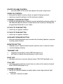
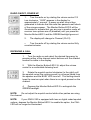
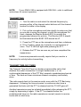
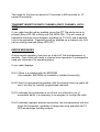
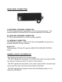
SMX-4150
OPERATOR’S MANUAL
INTRODUCTION
The SMX-4150 series mobile has 16 Channel capability, (enhanced to 99
with the selcall board fitted), with CTCSS and optional DCS signalling
systems..
FRONT PANEL CONTROLS, SWITCHES AND INDICATORS
ON/OFF/VOLUME CONTROL
•
turns the SMX-4150 on/off and adjusts the audio output level
SQUELCH CONTROL
• silences the radio's receiver when no signal is being received
• maximum squelch setting is at full clockwise rotation
CHANNEL CHANGE BUTTONS
• assigned (programmed) channels may be selected by pressing either of
the channel selector buttons; these buttons will scroll you through the
programmed channels in your radio
S FACILITY PUSH BUTTON
• used only on system mobiles
P FACILITY PUSH BUTTON
• used only on system mobiles
AUXILIARY SPEAKER BUTTON
• silences internal speaker and connects the Auxiliary Speaker (requires
auxiliary option board)
MONITOR BUTTON
• disables tone or digital coded squelch options (only in receive mode)
• controls display intensity
TRANSMIT LED
•
indicates transmission when RED backlight is on
•
will flash to indicate the synthesizer is out-of-lock
BUSY LED
• indicates activity on receive channel when YELLOW backlight is on
CALL LED
• indicates activity with the correct tone or code on the receive channel
when GREEN backlight is on
CHANNEL DISPLAY
• the BLUE-GREEN display is easily visible under high ambient light
conditions
• - indicates: channel number
RADIO ON/OFF, POWER UP
1.
Turn the radio on by rotating the volume control 1/2
turn clockwise. "4000" appears in the display for
approximately 1 second. A power up alert tone is then
generated to indicate that the radio has passed a self-check
of the microprocessor. The Monitor Button/LED 2 will be
illuminated to indicate that you are now in monitor mode; all
receiver tone options are off (disabled) until you press the
Monitor Button/LED 2 and the GREEN backlight goes out.
2.
The display will change to Channel (Ch:01).
Turn the radio off by rotating the volume control fully
counterclockwise.
3.
RECEIVING A CALL
1.
Turn the radio on and select the desired frequency by
pressing either of the channel select buttons until the channel
number is visible in the display.
2.
With the Monitor Button/LED 2 lit, adjust the volume
control to a comfortable listening level.
3.
Rotate the squelch control clockwise (to the right) until
the squelch noise (the rushing sound) is no longer heard from
the speaker and the BUSY LED turns off. This setting should
keep the receiver quiet when there is no signal present on the
channel.
4.
Depress the Monitor Button/LED 2 to extinguish the
GREEN backlight.
NOTE:
Do not adjust the squelch control while other parties are using
the channel.
NOTE:
If your SMX-4150 is equipped with tone or digital coded squelch
options, depress the Monitor Button/LED 2 to enable the option, the CALL
LED will no longer be illuminated.
NOTE:
If your SMX-4150 is equipped with SELCALL, refer to additional
instructions for correct operation.
TRANSMITTING
1. Turn the radio on and select the desired frequency by
pressing either of the channel select buttons until the channel
number is visible in the display.
2. Pick up the microphone and listen briefly to make sure that
no one else is using the channel, or with the microphone OnHook, depress the Monitor Button/LED 2 to monitor the
programmed channel for activity. The Monitor LED 2 should
be illuminated and the BUSY LED should be off.
3. Press the PTT bar on the microphone and from a distance
of 1/2 to 2 inches, speak into it directly in a normal tone of
voice. The TX LED will light while pressing the PTT.
4. Release the PTT bar as soon as you have completed the
transmission.
NOTE:
License requirements normally require that you monitor a
frequency for activity before transmitting.
TRANSMIT TIME-OUT-TIMER
The Transmit Time-Out-Timer is a dealer programmable option that
disables the radio's transmitter if a single transmission (i.e., an
uninterrupted depression of the PTT Bar) exceeds a predetermined period
of time. The time-out timer minimizes channel occupancy and battery
drain.
The radio reverts back to the receive mode, even with the PTT Bar being
depressed. Following the time-out period, a continuous alert tone is
generated that lasts until the PTT is released and the TX LED goes off.
Another transmission may be initiated immediately after releasing the PTT,
simply by depressing it again. If the PTT is released before the
predetermined time-out, the radio operates as normal (reverts to receive
mode with no alert tone).
The range for the time-out period is 10 seconds to 990 seconds (in 10
second increments).
TRANSMIT INHIBIT ON BUSY CHANNEL (BUSY CHANNEL LOCKOUT)
If your radio has this option enabled, press the PTT Bar while carrier is
present (Busy LED ON or Busy and Call LEDs ON). This will cause all
transmitter functions to be disabled, including the TX LED, and a warning
tone to be generated. Transmitting will be enabled on a channel only if no
carrier is being received (Busy LED OFF).
ERROR MESSAGES
During normal operation, from turn-on to shut-off, the microprocessor is
working. From initial self-check to channel scan operation it is designed to
keep you informed of its operating status.
If your radio displays:
Er:01 -There is a problem with the EEPROM
(For example, EEPROM not installed or installed incorrectly)
Er:02 -there is a programming problem with the channel data; the radio will
work, but only on correctly programmed channels
Er:03 -indicates the synthesizer is out of lock or a channel is out of
acceptable band; it is necessary to re-program or re-align the radio
Er:04 -indicates improper antenna connection; the microprocessor will shut
down the transmitter, generate a 3-beep alert tone and blink the TX
LED as warnings (usually omitted)
NOTE:
Should any of these messages appear on your display,
MAXON recommends that you consult the dealer from whom the unit was
purchased so that it can be serviced by a qualified service technician.
REAR PANEL CONNECTORS
A) EXTERNAL SPEAKER CONNECTOR
A 3.5mm diameter jack is provided for a 4 ohm external speaker. The
internal speaker is silenced when the external speaker is connected.
B) AUXILIARY SPEAKER CONNECTOR
A 3.5mm diameter jack for a 4 ohm auxiliary speaker.
C) ANTENNA CONNECTOR
SO-239 type connector. Output is 50 ohms and must be connected to a
properly installed .50 ohm antenna.
D) DC 13.2
Polarized plug: 13.2 volt DC input for NEGATIVE GROUND SYSTEM
ONLY.
GENERAL SAFETY INFORMATION
The following precautions are recommended:
- DO NOT operate the transmitter of a mobile radio when someone outside
the vehicle is within two feet (0.6 meter) of the antenna.
- DO NOT operate the transmitter of any radio unless all RF connectors are
secure and any open connectors are properly terminated.
- DO NOT operate this equipment near electrical blasting caps or in an
explosive atmosphere.
- All equipment must be properly grounded according to MAXON
installation instructions for safe operation.
- All equipment should be serviced only by a qualified technician.
Refer to the appropriate section of the product service manual for additional
pertinent safety information.
MAXON MOBILE INSTALLATION SAFEGUARDS
Some electronic fuel injection, anti-skid breaking systems, cruise controls,
and vehicle alarms may be prone to interference from radio frequency
energy or may malfunction due to lack of protection from RF energy. If the
vehicle contains such equipment, consult the dealer or factory and enlist
their help in determining whether the electronics equipment in the vehicle
will operate properly when the radio is transmitting.
• Do not install the unit where it would likely cause injury in case of vehicle
accident.
• Mount the unit so that the user can easily see and reach all controls and
the microphone.
• After selecting a location for the radio, hold the mounting bracket in
place. Using the bracket as a template, mark the spots where the
bracket securing screws will be located with a pencil.
• Before drilling holes in the vehicle, verify that there is nothing that could
be damaged or get in the way by drilling and putting screws in this
location.
• Try to get access to the back side of the surface where the bracket is to
be mounted, and verify that it is safe to use this location.
• It is better to use existing passages in the dashboard, trunk, and floor for
the routing of cables, thus avoiding excessive drilling.
NOTE: THIS RADIO IS NOT INTENDED FOR OPERATION IN A
POSITIVE GROUND VEHICLE!!!