1
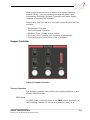
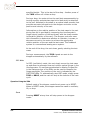
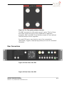
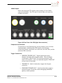
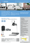
System Interface Module
(SIMx)
User's Manual
Version 1.01, DECEMBER 2012
© Copyright 2011 Micro-g LaCoste All Rights Reserved
Reproduction, adaptation, or translation without prior written permission is
prohibited, except as allowed under the copyright laws.
Publication Number 115-090-002A
Version 1.01, 05 October 2011
Applicable Products
Micro-g LaCoste: FGL, FG5 Absolute Gravimeter
Disclaimer
The information contained in this document is subject to change without notice.
Micro-g LaCoste makes no warranty of any kind. Micro-g LaCoste shall not be
liable for errors contained herein or for incidental or consequential damages in
connection with the furnishing, performance, or use of this material.
Contact
Micro-g LaCoste
1401 Horizon Avenue
Lafayette, Colorado 80026
USA
Tel: (303) 828-3499
Fax: (303) 828-3288
E-Mail: [email protected]
Website: www.microglacoste.com
Table of Contents
Section
Page
1.! Introduction........................................................................................................... 1-1!
Design ............................................................................................... 1-1!
Optional Tele-g/Remote Gravimeter Operation Package ............................ 1-1!
2.! System Interface Module ..................................................................................... 2-1!
Dropper Controller .............................................................................. 2-1!
Theory of Operation ................................................................... 2-1!
Operation Using the SIMx ............................................................ 2-2!
Superspring Controller ......................................................................... 2-4!
Theory of Operation ................................................................... 2-4!
Operation Using the SIMx ............................................................ 2-5!
System Level ...................................................................................... 2-5!
Software Interfaces (g INPUTS) ............................................................ 2-6!
Rear Connections ................................................................................ 2-7!
AC Input ................................................................................... 2-8!
Auxiliary AC Outputs................................................................... 2-8!
GPS Antenna ............................................................................. 2-8!
10MHz Outputs .......................................................................... 2-9!
Components Connections ............................................................ 2-9!
Trigger Connections.................................................................... 2-9!
ML-1 Laser Mode and Lock Mode ................................................ 2-10!
Analog Fringes In ..................................................................... 2-10!
USB Connection ....................................................................... 2-10!
Table of Contents
Version 1.01, Release Date 05 October 2011
i
List of Figures
Figure 2-1 Dropper Controller ........................................................................... 2-1!
Figure 2-2 Superspring Controller...................................................................... 2-4!
Figure 2-3 Auto-Leveling Portion of System Interface Module ................................ 2-6!
Figure 2-4 The Tele-g and g-software Interface ................................................... 2-7!
Figure 2-5 Rear View of the SIM........................................................................ 2-7!
Figure 2-6 Rear View of the SIM........................................................................ 2-7!
Figure 2-7 Rear View of the SIM (left side connectors) ......................................... 2-8!
Figure 2-8 Rear View of the SIM (right side connectors) ....................................... 2-9!
ii
Table of Contents
Version 1.01, Release Date 05 October 2011
Table of Contents
Version 1.01, Release Date 05 October 2011
iii
1. Introduction
1.
INTRODUCTION
Design ................................................................................................... 1-1
Optional Tele-g/Remote Gravimeter Operation Package ................................ 1-1
Design
The “X” version of the System Interface Module (SIMx) is a
flexible system designed to run the FGL, FG5, and FG5-X
absolute gravimeters. This system provides many different
functions: It interfaces with the system controller (computer)
providing analog and digital input and output, it controls the
dropping chamber and Superspring, and it houses the 10MHz
rubidium clock (and automatically syncs it with GPS). It
communicates via USB directly with the g-software Absolute
Gravity Data Acquisition and Processing Software (g-software,
described in detail in the g-software Absolute Gravity Data
Acquisition And Processing Software User's Manual).
Optional Tele-g/Remote Gravimeter Operation Package
The Tele-g/Remote Gravimeter Operation Package is optional
software and hardware that allows the FGL/FG5(X) to be
operated remotely via the internet. See the Tele-g/Remote
Gravimeter Operation User's Manual for additional information.
The Tele-g program runs in addition to the g-software, and it
allows the monitoring and control of a large portion of the
system components. These components include:
•
•
•
•
•
Monitor Dropper Controller Servo signal
Dropper Mode
Superspring position
Superspring Mode
Interferometric fringe amplitude measurement
In addition, the Tele-g/Remote Gravimeter Operation system
allows the following parameters to be adjusted through the
Tele-g interface:
Resetting the tilt position (and thus verticality) back to zero.
• Changing the Superspring position
• Enabling/Disabling the Superspring servo
• Changing the dropper controller mode
•
Introduction
Version 1.01, Release Date 05 October 2011
1-1
1-2
Introduction
Version 1.01, Release Date 05 October 2011
SYSTEM INTERFACE MODULE
Dropper Controller ................................................................................... 2-1!
Theory of Operation .............................................................................. 2-1!
Operation Using the SIMx ...................................................................... 2-2!
Superspring Controller .............................................................................. 2-4!
Theory of Operation .............................................................................. 2-4!
Operation Using the SIMx ...................................................................... 2-5!
System Level .......................................................................................... 2-5!
Software Interfaces (g INPUTS) ................................................................. 2-6!
Rear Connections ..................................................................................... 2-7!
AC Input .............................................................................................. 2-7!
Auxiliary AC Outputs ............................................................................. 2-8!
GPS Antenna ........................................................................................ 2-8!
10MHz Outputs ..................................................................................... 2-9!
Components Connections ....................................................................... 2-9!
Trigger Connections .............................................................................. 2-9!
ML-1 Laser Mode and Lock Mode ........................................................... 2-10!
Analog Fringes In ................................................................................ 2-10!
USB Connection .................................................................................. 2-10!
2.System Interface
Module
2.
Most system electronics are housed in the System Interface
Module (SIMx). This unit replaces the separate Patch Panel,
Superspring Controller, Dropper Controller and Power Supply
modules of previous FG5 systems.
Functionally, the front panel of the SIMx can be divided into five
sections:
•
•
•
•
•
The Dropper Controller
The Superspring Controller
Rubidium Clock (10MHz source) status
The Auto-Level Controller (not currently implemented).
The analog signal Patch Panel to the g-software.
Dropper Controller
Figure 2-1 Dropper Controller
Theory of Operation
The dropper controller can operate the dropping chamber in two
modes: DROP and OSC.
DROP Mode
In DROP mode, a manual press of the TRIG causes the motor in
the Dropping Chamber to lift the cart (and test mass) to a
System Interface Module
Version 1.01, Release Date 05 October 2011
2-1
specified height. This is the start of the drop. Another press of
the TRIG button will initiate a drop.
During a drop, the motor drives the cart/test mass assembly by
turning a pulley and stainless steel drive belt which is attached
to the cart. Attached to the shaft is an optical shaft encoder that
provides accurate information to the dropper controller on the
position and velocity of the cart.
Information on the relative position of the test mass to the cart
during free-fall is provided by comparing the interferometric
fringe output (position of the test mass) with the shaft encoder
information (position of the cart). The dropper controller uses
this information to determine whether to maintain, increase, or
decrease current to the motor to achieve the appropriate
relative position of the cart and the test mass. This feedback
system is a conventional analog servo system.
At the end of the drop, the cart slows, gently catching the test
mass.
During a measurement, the TRIG signals are sent to the
dropper automatically by the software.
OSC Mode
In OSC (oscillation) mode, the cart slowly moves the test mass
up and down to generate slow and uniform optical fringes in the
interferometer. An oscilloscope attached to Analog Fringes Out
in the Status portion of the SIMx can be used to measure the
fringe amplitude. The position of the cart is indicated by the
CART POS LEDs. To automatically stop OSC mode, simply press
TRIG or DROP, and the cart will stop at the bottom of the next
cycle.
Operation Using the SIMx
Default mode of the dropper controller at power-up is RESET.
When in RESET mode, the dropper cannot be made to oscillate,
lift, or drop.
Reset
Pressing RESET at any time will stop power to the dropper
motor.
2-2
System Interface Module
Version 1.01, Release Date 05 October 2011
Drop
Pressing DROP will put the dropper in drop mode. In this mode,
pressing TRIG will:
Cart at the bottom. Pressing TRIG will lift the cart to the top
of its travel
• Cart at the top. Pressing TRIG will initiate the drop sequence
in which the cart places the test mass in freefall and then
gracefully catches it at the bottom
•
The dropper should be in DROP mode for data acquisition. The
CART POS LEDs indicates the position of the cart.
OSC
Pressing OSC will put the dropper in oscillation mode. In this
mode, pressing TRIG will:
•
Cause the cart to slowly and repeatedly go up and down to
generate slow fringes for optical alignment purposes.
Pressing TRIG or DROP will stop OSC mode at the end of the
current cycle.
BNC Outputs for Dropper Controller
There are three BNC outputs for the Dropper Controller.
TRIG OUT sends out a logic pulse when the drop has been
initiated. This is normally used to trigger the Time Interval
Analyzer card in the system controller (computer).
• OBJECT POS can be used to read out the position of the test
mass relative to the cart during a drop. As the distance
increases during the freefall portion of the drop, the voltage
output increases. The voltage drops back to zero when the
test mass is caught by the cart at the end of the drop.
• CART POS can be used to read out the position of the cart
relative to the dropping chamber.
•
System Interface Module
Version 1.01, Release Date 05 October 2011
2-3
Superspring Controller
Figure 2-2 Superspring Controller
Theory of Operation
The Superspring is an electro-mechanical system designed to
isolate the reference mass from any vertical motion (typically
due to micro-seismic noise) during the measurement. A
position-feedback, linear actuator coil/magnet system maintains
the position of the reference mass, and a motor attached to the
top of the mainspring, as well as an aneroid wafer assembly
keep the position fixed over long period changes in temperature
(and/or local gravity).
A sphere detector system provides information on the position
of the reference mass relative to the mainspring support
system. An infrared LED and a photo detector are mounted
opposite each other inside the mainspring support housing. A
sphere attached to the bottom of the mass focuses the light
from the LED onto the detector, which transmits the resulting
signal to a sphere signal preamplifier.
Changes in temperature, or moving the gravity meter to a new
location that has a significantly different local gravity, can
change the length of the main spring. In some cases, this
change may even move the sphere signal off of the small
detector. The position of the test mass can be adjusted by
2-4
System Interface Module
Version 1.01, Release Date 05 October 2011
moving the top of the main spring with a small DC motor with a
very large gear ratio for fine control.
The main servo electronics control, the coil-magnet forcer,
moves the main spring support in such a way to keep the
position of the reference mass constant relative to the detector.
This active servo effectively weakens the main spring,
synthesizing a long period isolation device. The active period of
the Superspring is nominally about 60 seconds.
Operation Using the SIMx
ZERO
ZERO is used to automatically position the Superspring
corner-cube in the center of the detector range. With the
Superspring travel lock disengaged, monitor the SPHERE
position using a DC-coupled voltmeter. Once the voltage has
settled down to a few 10s of mV, enable ZERO. The spring
should come to within approximately 50 mV of zero.
SERVO
SERVO is used to enable the servo circuit on the Superspring.
The two functions are mutually exclusive: one cannot zero the
spring while the servo is enabled, and vice-versa. Once the
spring has settle down near the zero position, enable SERVO.
This activates the feedback system, isolating the reference mass
from ground noise. Note that the SERVO must be enabled while
acquiring gravity data!
BNC Outputs for Superspring Controller
There are two BNC outputs in the Superspring controller.
SPHERE is a voltage proportional to the location of the
Superspring corner-cube. Ideally this is within 100 mV or so of
zero.
• COIL is a voltage proportional to the current being applied to
the coil-magnet mechanism. Ideally, after the spring has come
to equilibrium, this is constant at zero.
•
See the FG5 Absolute Gravimeter User's Manual for details.
System Level
System Interface Module
Version 1.01, Release Date 05 October 2011
2-5
Figure 2-3 Auto-Leveling Portion of System Interface Module
Note that automatic tilt monitoring/correction is currently
disabled in the FG5-X.
Software Interfaces (g INPUTS)
The software interface to the g-software Absolute Gravity Data
Acquisition and Processing Software is shown in Figure 2-4.
Refer to the g-software Absolute Gravity Data Acquisition And
Processing Software User’s Manual for information on the
software.
2-6
System Interface Module
Version 1.01, Release Date 05 October 2011
Figure 2-4 The Tele-g and g-software Interface
The BNC connectors in this section are all inputs. The Ion Pump
and Laser inputs are used in the g Software for diagnostic
purposes. AUX 1 and AUX 2 are auxiliary inputs for user defined
functions and/or future upgrades.
For past FG5 users, note that the rest of the connections
(barometer, triggers, Superspring sphere) are now all connected
internally.
Rear Connections
Figure 2-5 Rear View of the SIM
Figure 2-6 Rear View of the SIM
System Interface Module
Version 1.01, Release Date 05 October 2011
2-7
Figure 2-7 Rear View of the SIM (left side connectors)
AC Input
The SIMx is designed for universal AC input power: 100240VAC, 50/60Hz.
Auxiliary AC Outputs
Three auxiliary AC outputs are provided for external
components: system computer, ion pump power supply, etc.
GPS Antenna
When connected to a GPS antenna, the SIMx can use the
satellite information to synchronize with g-software (setting
system clock time and providing location information) and it can
discipline the internal rubidium clock to a cesium-based
“perfect” 10MHz. When lock is achieved and LED on the front
panel with illuminate.
WARNING
2-8
The clock will be disciplined to 10MHz only after GPS lock is
attained, and then while the SIMx is powered on (even if GPS
lock is lost). If the system is restarted, the clock will revert to
its own internal frequency. It is important to use the correct
frequency in the g-software Advanced Settings Setup!
System Interface Module
Version 1.01, Release Date 05 October 2011
10MHz Outputs
Both sine wave and TTL square wave outputs of the 10MHz
clock are available. The TIA card in the ex-Box unit uses the
10MHz sine wave.
Figure 2-8 Rear View of the SIM (right side connectors)
Components Connections
Connections to the Superspring, leveling system (not currently
implemented), interferometer APD power, and dropper
controller Encoder and Motor are now built into the SIMx (unlike
previous SIM versions).
Trigger Connections
•
DROPPER TRIGGER OUT. Digital signal sent when
dropper lifts and when dropper drops. This should be
connected to ARM on the Time Interval Analyzer (TIA)
card in the ex-Box. This is a duplicate signal of TRIG OUT
on the front of the SIMx.
•
TRIGGER IN. Used to externally trigger the dropper
controller.
•
COMPUTER TRIGGER OUT. Used to externally trigger a
second Dropper Controller when debugging additional
gravity meter systems.
System Interface Module
Version 1.01, Release Date 05 October 2011
2-9
ML-1 Laser Mode and Lock Mode
The laser mode and lock are for communication with an optional
ML-1 HeNe laser. (See the ML-1 Polarization Stabilized Laser
Operator's Manual for details.)
Analog Fringes In
A BNC from ANALOG FRINGES on the interferometer base (IB)
should be connected here. This fringe signal is used on the
front of the SIMx for alignment/set up purposes and the signal
is used to provide test mass position information to the Dropper
Controller circuit.
USB Connection
A type “B” USB cable connects the SIMx to the system controller
(laptop). This signal is used to send analog sensor information
(laser 1f values, barometer, ion pump current, etc.) to
g-software, and it also communicates digital trigger information
from the software to the Dropper Controller and Superspring
controllers.
2-10
System Interface Module
Version 1.01, Release Date 05 October 2011
System Interface Module
Version 1.01, Release Date 05 October 2011
2-11