1
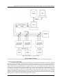
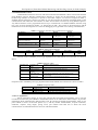
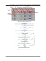
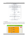
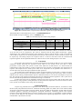
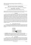
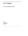
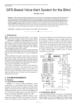
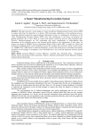
IOSR Journal of Electronics and Communication Engineering (IOSR-JECE)
e-ISSN: 2278-2834,p- ISSN: 2278-8735.Volume 10, Issue 6, Ver. I (Nov - Dec .2015), PP 01-09
www.iosrjournals.org
Development of Distributed Mains Monitoring and Switching
System for Indus Complex
Neeraj Chandnani1, A.M. Gupta2, Pravin Fatnani2, Preet Jain1
1
(Department of Electronics and Communication Engineering, Shri Vaishnav Institute of Technology and
Science, Indore, India)
2
(Accelerator Control Section, Raja Ramanna Centre for Advanced Technology, Indore, India)
Abstract: Indus Complex at Raja Ramanna Centre for Advanced Technology (RRCAT) has two synchrotron
radiation sources, Indus-1 and Indus-2. Microtron is injector to both the machines which sends electron pulses
to the Booster. A new, microcontroller based, distributed mains monitoring and switching system is developed
for Indus complex. It facilitates remote monitoring and switching of AC power switches to various subsystems. It
includes interfacing with power switches/Miniature Circuit Breakers (MCBs) of Indus machine subsystems. This
work involves development of hardware, firmware for microcontroller, implementation of communication
protocol; LabVIEW based server and client application. The developed system allows remote monitoring and
switching of MCBs from main control room.
Keywords: Microcontroller, LabVIEW, Protocol, MCB, Power
I.
Introduction
In RRCAT, Indus complex is having many subsystems associated with Microtron, Booster, Indus-1 and
Indus-2. During machine startup and shut down, operation crew needs to switch many MCBs and when machine
operation is interrupted because of any fault these MCBs are needed to be checked as a procedure for debugging.
If the status of all MCBs is made available in the main control room it will be helpful and will improve operation
activity. To fulfill the requirement an AC power status monitoring and switching system has been planned. Fig.1
shows the block diagram of complete system. It consists of server, client and microcontroller based field modules
interfaced with MCBs. Real time database storing facility is also provided for offline analysis.
Server communicates to field modules over RS-485 network. Communication between server and client
is implemented over Ethernet. The system senses line phases (R, Y, B) through optical fiber to provide physical as
well as electrical isolation. A distributed AC mains power monitoring and switching system is developed which
allows remote monitoring and controlling of power input to various subsystems. Indus complex is distributed over
large area; there are so many subsystems whose input AC power status is to be checked for debugging. At present
operation crew checks the status of various MCBs manually. It takes a lot of time to check for the various MCBs.
So, a system is developed which provides the status of MCBs at one place, hence it saves time.
II. Literature Survey
The Literature survey is done to collect information about other systems available in market. One similar
type of system developed by Starkstrom Company, UK, named as “MCB Trip Monitoring Module (MTMM)”[1].
Comparison between this system and developed system is shown in table 1.
Table 1: Comparison between developed system and similar systems
S.NO.
1
2
3
4
5
6
7
Developed System
Modification is easy
Firmware is developed in such a manner that it can
be used for other applications as well
Up-gradation and maintenance done in house
High voltage isolation through fiber optics
Low cost
PC interface, data-logging implemented
Monitoring and control both features implemented
DOI: 10.9790/2834-10610109
MCB Trip Monitoring Module (MTMM)
Modification is not possible
Firmware is copyright
Depends upon vendor
Isolation through transformer only
Costly than developed system
Only local monitoring available by means of LEDs.
Only monitoring available
www.iosrjournals.org
1 | Page
Development of Distributed Mains Monitoring and Switching System for Indus Complex
Fig.1: Block diagram of complete system
III. System Descriptions
The system consists of microcontroller field modules, firmware for microcontroller, server and client application.
3.1 Microcontroller field module
As shown in fig.2, addressable Microcontroller based field modules communicates with server. Eight bit
DIP switch is used to set address of field modules and addresses are settable from 1 to 255. Auto module detection
and registration feature is incorporated in the system. As the field modules connected on the RS485 network, server
checks communication with field modules and registers address of it in server database and starts communication
automatically. All connected Microcontroller modules are in listening mode therefore as command sent by server
to a particular module then only addressed module sends response. The communication mode is half duplex, and
single master type hence at a time only one field module communicates with server. In case if two modules
addresses matched due to human mistake then server receives check-sum error and tries multiple times to get the
response from the module and finally declares that address faulty and blocks communication with the particular
address/addresses. Field module Inputs/Outputs details are as follows:
DOI: 10.9790/2834-10610109
www.iosrjournals.org
2 | Page
Development of Distributed Mains Monitoring and Switching System for Indus Complex
Table 2: Microcontroller module I/O signal description
Name of Signal
R
Y
B
ST1
ST2
ST3
RL1
RL2
RL3
Type of signal
Input
Input
Input
Input
Input
Input
Output
Output
Output
Description
„R‟ Electrical Phase status
„Y‟ Electrical Phase status
„B‟ Electrical phase status
Contact status of RL1
Contact status of RL2
Contact status of RL3
Potential free relay contact
Potential free relay contact
Potential free relay contact
Fig.2: Schematic block diagram
DOI: 10.9790/2834-10610109
www.iosrjournals.org
3 | Page
Development of Distributed Mains Monitoring and Switching System for Indus Complex
3.2 Communication Protocol
Communication between server PC and microcontroller field modules is done over RS-485 network
using Modbus protocol. RS-485 communication interface is chosen for the development of the system
because large number of subsystems is present in the Indus complex. As shown in comparison table 3,
standard RS-485 transceiver supports 32 nodes on one physical network with the maximum length of the
communication link 4000 feet. The number of nodes can be further increased by using RS485 repeaters.
Any Microcontroller can be programmed and set-up to communicate on standard Modbus network using
two types of serial transmission modes: (1) ASCII and (2) RTU. This system is developed using ASCII
mode because of its advantage that it is easier for debugging if any problem occurs during communication.
Table 3: Comparison between serial communication interfaces
Specifications
Communication
Communication Mode
RS-232
Peer to peer
Simplex or full duplex
Mode of Operation
Total Number of Drivers and
Receivers on One Line
Maximum Cable Length
Maximum Data Rate (40 feet - 4000
feet for RS-422/RS-485)
Single-Ended
1 Driver
1 Receiver
50 feet (2500 pF)
160 Kbits/s (can
be up to 1Mbit/s)
RS-422
Peer to peer
Simplex or half duplex
or full duplex
Differential
1 Driver
10 Receivers
4000 feet
10 Mbit/s
RS-485
Multidrop
Simplex or half duplex
or full duplex
Differential
32 Drivers
32 Receivers
4000 feet
10 Mbit/s
Table 4: ASCII command frame
FIELD
CHAR LENGTH
START
1 CHAR
:
ADDRESS
2 CHARS
FUNCTION
n CHARS
DATA
2 CHARS
LRC CHECK
2 CHARS
END
2 CHARS
CRLF
Function codes of Modbus protocol [2] implemented for P89C51RD2 microcontroller are shown in
table 5.
Table 5: Function codes
Function Code
01
02
03
05
06
Function Code
Name
Read Coil Status
Read Input Status
Read Holding
Registers
Force Single Coil
Diagnostic Sub
function
Working of Function Code
It reads all ports (P0, P1, P2, P3) of microcontroller bit wise.
It reads all ports of microcontroller byte wise.
It gives the information about the SFR of microcontroller.
It writes the user defined hex value to the desired port of
microcontroller.
It echoes backs the transmitted frame in response.
Exception Codes of Modbus protocol [2] implemented for P89C51RD2 microcontroller are shown in table 6:
Table 6: Exception codes
Exception Code
01
02
03
Exception Code Name
Illegal Function
Illegal data address
Illegal data value
Working of Exception Code
Function Code not supported.
Address not available/wrong address.
Data value out of range/wrong data value.
3.3 Server Application
Server application running at server PC polls the Microcontroller field modules one by one and
records the status of AC power MCBs in the database which can be referred for offline analysis. It provides
information about communication link between server PC and microcontroller field modules, status of AC
power MCBs in terms of electrical phases (R, Y, and B), module enable/disable, response indication,
checksum, response string length, poling count, port number and baud rate at which the serial
communication is established between server PC and field modules.
DOI: 10.9790/2834-10610109
www.iosrjournals.org
4 | Page
Development of Distributed Mains Monitoring and Switching System for Indus Complex
Fig.3: Server Application front panel GUI
Fig.4: Microcontroller firmware flow chart
DOI: 10.9790/2834-10610109
www.iosrjournals.org
5 | Page
Development of Distributed Mains Monitoring and Switching System for Indus Complex
Fig.5: Server Application flow chart
3.4 Client Application
Client application running at client PC is connected with server application running at server PC,
over Ethernet. Client application provides information about server to client communication link, MCBs
status in terms of electrical phases (R, Y, and B), communication link indication of server and field
microcontroller modules. ON/OFF button is provided in the client application for remotely switching the status
of MCBs.
Fig.6: Client Application front panel GUI
DOI: 10.9790/2834-10610109
www.iosrjournals.org
6 | Page
Development of Distributed Mains Monitoring and Switching System for Indus Complex
IV. Results
The real time analysis of signal is carried out with the help of digital Oscilloscope, Agilent
Technologies. The length of command frame is fixed for all function codes. The duration of command frame for
all function codes is 17.55ms. The command frame, response frame and Enable signals waveform are taken at
RX, TX and EN pin of microcontroller respectively for the implemented function codes are as follows:
Command frame sent by server
17.55 ms
Echo of response frame
Response frame received by server
13.45 ms
Enable Signal
Figure 7: Command frame, response frame and Enable signals for Function Code 01
Transmitted data of command frame by server: “:7D0100800003FF\r\n”
Received data of response frame by server: “:7D0101077A\r\n”
Command frame sent by server
17.55 ms
Echo of response frame
Response frame received by server
15.55 ms
Enable Signal
Figure 8: Command frame, response frame and Enable signals for Function Code 03
Transmitted data of command frame by server: “:7F0300E0000896\r\n”
Received data of response frame by server: “:7F0301002B52\r\n”
Command frame sent by server
Echo of response frame
17.55 ms
Response frame received by server
17.55 ms
Enable Signal
Figure 9: Command frame, response frame and Enable signals for Function Code 05
Transmitted data of command frame by server: “:010500A000FF5B\r\n”
Received data of response frame by server: “:010500A000FF5B\r\n”
DOI: 10.9790/2834-10610109
www.iosrjournals.org
7 | Page
Development of Distributed Mains Monitoring and Switching System for Indus Complex
Command frame sent by server
17.55 ms
Echo of response frame
Response frame received by server
Enable Signal
11.45 ms
Figure 10: Command frame, response frame and Enable signals for Exception Responses
Transmitted data of command frame by server: “:0A0900A000FF4E\r\n”
Received data of response frame by server: “:0A89016C\r\n”
Table 7: Command, Response frame timing analysis
Command Frame (time in ms)
Response Frame (time in ms)
:7D0100800003FF\r\n (17.55)
:7F0300E0000896\r\n (17.55)
:010500A000FF5B\r\n
(17.55)
:0A0900A000FF4E\r\n
(17.55)
:7D0101077A\r\n (13.45)
:7F0301002B52\r\n (15.55)
:010500A000FF5B\r\n (17.55)
:0A89016C\r\n
(11.45)
Enable pulse
time (ms)
1.2
1.2
1.2
Processing
time (ms)
1.05
0.95
1.15
Total time
(ms)
33.25
35.25
37.45
1.2
0.7
30.90
From table 5.1, it has been noted that total frame time for function codes 01, 03 and 05 are 33.25 ms,
35.25 ms and 37.45 ms respectively. The result is analyzed with the help digital Oscilloscope, Agilent
Technologies. The command and response frame length for function code 02 and 08 is same as the function
code 01 and 05 respectively. So the timing analysis for function code 02 and 08 is same as function code 01 and
05 respectively. The timing analysis for exception code 01 is shown in the table. Since the command and
response length for all the implemented function codes are same so their timing analysis is also same.
V. Conclusion
The system is developed in the Accelerator Development Lab (ADL) at RRCAT. This system enables
automation thereby improving the operation activity. Heat on test carried out for four days to check
performance of the system. The system is tested at the baud rate of 9600 bits/sec. It is observed that for
communication at Rs-485 interface, it takes around 40 ms from reception of command to the transmission of
response. This implies that AC mains power status of 25 subsystems can be updated at this baud rate in 1
second. Hence the system has improved Indus machine operation.
The system will provide information of status of electrical phases in terms of R, Y, and B in real time.
A graphical user interface (GUI) is developed which is helpful in observing the status easily. Status of control
outputs ensures working of field modules. System is efficient and has low cost. Power consumption of system is
less. This system can be used for monitoring and control of industrial and home appliances. This system can be
used in restricted and prohibited areas where human being is not allowed.
In future the system can be upgraded to monitor input power status of more than 32 subsystems. This
can be done by using repeaters. Other parameters of subsystems like temperature can also be shown at control
room. System can be made wireless using Wi-Fi technology.
Acknowledgements
I express my profound sense of gratitude to Mr. A.M. Gupta, Scientific Officer/F, Accelerator Control
Section (ACS), Raja Ramanna Centre for Advanced Technology (RRCAT), Indore, Mr. Pravin Fatnani, Head,
Accelerator Control Section, RRCAT, Indore and Mr. Preet Jain, Head, EC department, SVITS, Indore for their
invaluable guidance, persisting encouragement, perceptual motivation, everlasting patience and excellent
expertise in discussion benefited me to proceed. I sincerely wish to express, my gratefulness to all the members
of staff of ACS, RRCAT and Electronics and Communication Engineering Department, SVITS who have
extended their cooperation at all times.
DOI: 10.9790/2834-10610109
www.iosrjournals.org
8 | Page
Development of Distributed Mains Monitoring and Switching System for Indus Complex
References
[1]
[2]
[3]
[4]
[5]
[6]
[7]
MCB-Trip-Monitoring-Module: http://www.starkstrom.com/assets/Uploads/MCB-Trip-Monitoring-Module.pdf
Modicon Modbus Protocol Reference Guide: http://modbus.org/docs/PI_MBUS_300.pdf
Microcontroller P89C51RD2 datasheet: http://netmedia.com/siteplayer/docs/001212/Philips_P89C51RD2_6.pdf
Muhammad Ali Mazidi, Janice Gillispie Mazidi, Rolin D. Mckinlay: The 8051 Microcontroller and Embedded Systems
using Assembly and C, second edition.
LabVIEW User Manual: http://www.ni.com/pdf/manuals/320999b.pdf
Rick Bitter, Taqi Mohiuddin, Matt Nawrocki: LabVIEW Advanced Programming Techniques, second edition (2007).
Barry E. Paton: Sensors, Transducers, & LabVIEW, Prentice Hall PTR, 1999.
DOI: 10.9790/2834-10610109
www.iosrjournals.org
9 | Page