1
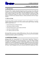
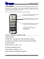
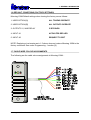
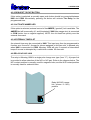
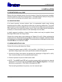
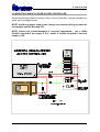
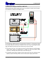
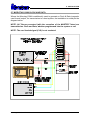
Microtag 100 Mullion Reader
User Manual
Version A1 July ‘01
Table of Contents
1. GENERAL INFORMATION
1
1.1 DESCRIPTION . . . . . . . . . . . . . . . . . . . . . . . . . . . . . . . . 1
1.2 APPLICATIONS
. . . . . . . . . . . . . . . . . . . . . . . . . . . . . . . 1
1.3 CARDS/TAGS (TOKENS) . . . . . . . . . . . . . . . . . . . . . . . . . . 1
1.4 PROGRAMMING . . . . . . . . . . . . . . . . . . . . . . . . . . . . . . . 2
1.5 HOW TO REPLACE A LOST MASTER TOKEN . . . . . . . . . . . . . . . 2
1.6 DEFAULT CONDITIONS (FACTORY SETTINGS) . . . . . . . . . . . . . . 3
1.7 CABLE WIRE COLOUR ASSIGNMENTS . . . . . . . . . . . . . . . . . . 3
2. FEATURES
4
3. SPECIFICATION
5
4. OPERATION
6
4.1 GENERAL
. . . . . . . . . . . . . . . . . . . . . . . . . . . . . . . . . . 6
4.2 USER CARDS/TAGS (TOKENS) . . . . . . . . . . . . . . . . . . . . . . . 6
4.3 OUTPUTS
. . . . . . . . . . . . . . . . . . . . . . . . . . . . . . . . . . 6
4.4 INPUT #1 . . . . . . . . . . . . . . . . . . . . . . . . . . . . . . . . . . . 7
4.4.1 INPUT #1 UNUSED
. . . . . . . . . . . . . . . . . . . . . . . . . . . . 7
4.4.2 DOOR MONITOR INPUT . . . . . . . . . . . . . . . . . . . . . . . . . . 7
4.4.3 ACTIVATE RED LED . . . . . . . . . . . . . . . . . . . . . . . . . . . . 8
4.4.4 FIRE MONITOR INPUT
. . . . . . . . . . . . . . . . . . . . . . . . . . 8
4.4.5 KEYSWITCH INPUT . . . . . . . . . . . . . . . . . . . . . . . . . . . . 8
4.5 INPUT #2 . . . . . . . . . . . . . . . . . . . . . . . . . . . . . . . . . . . 8
4.5.1 INPUT #2 UNUSED
. . . . . . . . . . . . . . . . . . . . . . . . . . . . 8
4.5.2 REQUEST TO EXIT BUTTON . . . . . . . . . . . . . . . . . . . . . . . 9
4.5.3 ACTIVATE AMBER LED . . . . . . . . . . . . . . . . . . . . . . . . . . 9
4.5.4 EXTERNAL TIME SLOT . . . . . . . . . . . . . . . . . . . . . . . . . . 9
4.6 RELAY N/O N/C LINK . . . . . . . . . . . . . . . . . . . . . . . . . . . . 9
4.7 SYSTEM OPTIONS
. . . . . . . . . . . . . . . . . . . . . . . . . . . . 10
4.7.1 CLEAR OPTIONS
. . . . . . . . . . . . . . . . . . . . . . . . . . . . 10
4.7.2 ANTI-TAILGATING . . . . . . . . . . . . . . . . . . . . . . . . . . . . 10
4.7.3 CROSS INTERLOCK . . . . . . . . . . . . . . . . . . . . . . . . . . . 10
4.7.4 CLOCK AND DATA OUTPUT . . . . . . . . . . . . . . . . . . . . . . 11
4.7.5 TAMPER/LOCKOUT WARNING . . . . . . . . . . . . . . . . . . . . . 11
4.7.6 DOOR FORCED WARNING . . . . . . . . . . . . . . . . . . . . . . . 11
4.7.7 DOOR LEFT OPEN WARNING
. . . . . . . . . . . . . . . . . . . . . 11
5. INSTALLATION
12
5.1 MOUNTING Microtag 100M . . . . . . . . . . . . . . . . . . . . . . . . 12
5.2 CABLE ROUTING . . . . . . . . . . . . . . . . . . . . . . . . . . . . . 12
5.3 WIRING MICROTAG 100M . . . . . . . . . . . . . . . . . . . . . . . . . 12
5.4 MICROTAG 100M AS A DOOR ACCESS CONTROLLER
. . . . . . . . 13
5.5 MICROTAG 100M AS A CONTROL PANEL KEY . . . . . . . . . . . . . 14
5.6 MICROTAG 100M CROSS INTERLOCKED . . . . . . . . . . . . . . . . 15
5.7 MICROTAG 100M CLOCK AND DATA
6. PROGRAMMING MICROTAG 100M
. . . . . . . . . . . . . . . . . . 16
17
6.1 ADD NEW USER(S) TO SYSTEM . . . . . . . . . . . . . . . . . . . . . 18
6.2 DELETE USER(S) FROM SYSTEM . . . . . . . . . . . . . . . . . . . . 19
6.3 DELETE PAGE OF USERS FROM SYSTEM . . . . . . . . . . . . . . . 19
6.4 PROGRAM USER OPTIONS . . . . . . . . . . . . . . . . . . . . . . . . 20
6.5 PROGRAM INPUT #1 OPTIONS . . . . . . . . . . . . . . . . . . . . . . 21
6.6 PROGRAM INPUT #2 OPTIONS . . . . . . . . . . . . . . . . . . . . . . 22
6.7 PROGRAM OUTPUT TIMERS . . . . . . . . . . . . . . . . . . . . . . . 22
6.8 PROGRAM SYSTEM OPTIONS . . . . . . . . . . . . . . . . . . . . . . 24
6.9 RESTORE MICROTAG 100M TO FACTORY SETTINGS . . . . . . . . . 24
TERMS & CONDITIONS
25
1. GENERAL INFORMATION
1. GENERAL INFORMATION
1.1 DESCRIPTION
Microtag 100M is a highly integrated stand-alone proximity access control reader and
controller for up to 100 users. Microtag 100M is easily programmable on site using the
master Token provided. Microtag 100M is fully potted against the ingress of moisture,
and is therefore suitable for use outdoors. The narrow profile of the Microtag 100M
makes it particularly suitable for mullion mounting. Microtag 100 though simple in
operation, provides many advanced features, normally associated with much larger
systems.
1.2 APPLICATIONS
The Microtag 100M is primarily intended for access control applications. Its custom
software is designed for ease of use, and provides a wide range of features. Microtag
100M is ideally suited as a...
*
DOOR ENTRANCE ACCESS SYSTEM
*
CAR PARK ACCESS SYSTEM
*
KEYPAD/ZONE SHUNT FOR ALARM SYSTEMS
*
AIR-LOCK ACCESS SYSTEM
*
LIFT USER ACCESS SYSTEM.
Microtag 100M is housed in a durable ABS enclosure. The unit is fully potted against
the ingress of moisture. The unit is designed to be surface mounted, the narrow profile
making it particularly suitable for mullion fitting.
1.3 CARDS/TAGS (TOKENS)
Microtag 100M can accommodate up to 100 proximity Cards/Tags (Tokens), a
MASTER (Programming) Token is provided with the unit. Any Token may be assigned
to operate any combination of three programmable outputs. Any Token may be
assigned to an external timer (time slot), or may be assigned temporary status (remains
valid for 24 hours). The MASTER (Programming) Token is the only device that allows
access to the programming functions. The USER TOKEN can only operate the system.
All Tokens can be changed at any time by using the MASTER (Programming) Token.
Microtag 100M User Manual
1
1. GENERAL INFORMATION
1.4 PROGRAMMING
Microtag 100M is programmed on site using the MASTER (Programming) Token
provided with the unit. Programming is simple, and is assisted visually by means of the
three status LEDs and audibly by the buzzer.
Refer to the following figure for the position of the LED indicators.
Power “on” Indicator. Also used as status
indicator during programming.
Access “denied” Indicator. Also used as
status indicator during programming.
Access “granted” Indicator. Also used as
status indicator during programming.
NOTE: Amber and red led’s are
programmable for use by
external systems
1.5 HOW TO REPLACE A LOST MASTER TOKEN
[1] REMOVE POWER
[2] TEMPORARILY DISCONNECT IN#1 AND IN#2 (BROWN & ORANGE)
[3] JOIN IN#1 AND IN#2 WIRES TOGETHER (AWAY FROM OTHER WIRING)
[4] RESTORE POWER
[5] UNIT SOUNDS... ALL LEDS —> ON
[6] PRESENT NEW MASTER TOKEN
[7] UNIT SOUNDS... GREEN LED —> ON
[8] RE-CONNECT INPUTS REMOVED IN [2] ABOVE
Microtag 100M User Manual
2
1. GENERAL INFORMATION
1.6 DEFAULT CONDITIONS (FACTORY SETTINGS)
Microtag 100M Default settings when leaving the factory are as follows:
1. USER OPTION [A]
ALL TOKENS OPERATE
2. USER OPTION [B]
ALL OUTPUTS OPERATE
3. OUTPUTS 1,2 AND RELAY
5 SECONDS
4. INPUT #1
ACTIVATES RED LED
5. INPUT #2
REQUEST TO EXIT
NOTE: Replacing a lost master as in 1.5 above does not restore Microtag 100M to the
factory conditions. See under Programming... function [9].
1.7 CABLE WIRE COLOUR ASSIGNMENTS
The following are the cable colour assignments in Microtag 100M...
Microtag 100M User Manual
3
2. FEATURES
2. FEATURES
*
100 CARD/TAG (TOKEN) CAPACITY
*
PROGRAMMED ON SITE USING MASTER TOKEN
*
NON VOLATILE MEMORY FOR TOKENS /PROGRAMMING
*
TEMPORARY (24 HOUR) TOKEN FACILITY
*
PROGRAMMABLE ANTI-TAMPER SWITCH
*
RELAY OUTPUT N/O AND N/C SELECTABLE
*
THREE PROGRAMMABLE TRANSISTOR OUTPUTS
*
PROGRAMMABLE CROSS INTERLOCK INPUT/OUTPUT
*
OUTPUTS 1 SECOND TO 99 MINUTES OR LATCHED (TOGGLE)
*
RED LED PROGRAMMABLE FOR USE WITH EXTERNAL SYSTEMS
*
AMBER LED PROGRAMMABLE FOR USE WITH EXTERNAL SYSTEMS
*
TWO PROGRAMMABLE INPUTS
*
EXTERNAL KEY CONTROL INPUT
*
EXTERNAL TIME CONTROL INPUT
*
DOOR LEFT OPEN MONITOR INPUT
*
ANTI-TAILGATE FUNCTION
*
DOOR FORCED ALARM OUTPUT
*
FIRE ALARM INPUT
*
OPEN DOOR (REQUEST TO EXIT) FACILITY
*
PROGRAMMABLE CLOCK AND DATA OUTPUT
*
FULLY POTTED ELECTRONICS
*
uEM 125 KHz CARD/TAG COMPATIBLE
*
MULLION MOUNTING
Microtag 100M User Manual
4
3. SPECIFICATION
3. SPECIFICATION
POWER SUPPLY :
10.5-16 V DC REGULATED
CURRENT CONSUMPTION :
60 m/A MAX (STANDBY)
RELAY OUTPUT :
VOLTAGE FREE N/O OR N/C
CONTACTS RATED 2.0A @ 24V
DC. PROGRAMMABLE
MOMENTARY OR LATCHED
OUTPUT 1 :
OPEN COLLECTOR TRANSISTOR
MAX. SINK CURRENT 100mA.
OUTPUT 2 :
OPEN COLLECTOR TRANSISTOR
MAX. SINK CURRENT 100mA.
OUTPUT 3 :
OPEN COLLECTOR CROSS-LOCK
(INPUT)/OUTPUT.
PROXIMITY CARDS/TAGS
uEM FORMAT COMPATIBLE
FREQUENCY 125 KHz
I.P. RATING :
IP 4.6 (WITH BUZZER SEALED)
OPERATING TEMPERATURE :
-30 C TO +50 C 0-90% RH
(NON-CONDENSING)
CONSTRUCTION :
ABS ENCLOSURE, ELECTRONICS
FULLY POTTED
WEIGHT :
APPROX. 200g
SIZE :
WIDTH 44mm, HEIGHT 115mm,
DEPTH 22mm
Microtag 100M User Manual
5
4. OPERATION
4. OPERATION
4.1 GENERAL
Microtag 100M requires a suitable power supply. This supply must be well regulated,
with very low supply ripple. The proximity reader contains a very sensitive RF receiver,
and care should be taken to keep the unit away from sources of electrical noise.
Proximity cards/tokens should be uEM format 125KHz compatible. Depending on the
type of card/token in use, read range can be up to 150mm. Microtag 100M may decode
other proximity card/token formats with reduced read range.
Proximity readers should be kept at least 1 metre away from each other to avoid
mutual interference.
4.2 USER CARDS/TAGS (TOKENS)
The USER TOKENS (#1 to #100) may be individually programmed to operate any
output combination. The PROGRAMMING TOKEN (supplied) is used to
introduce/delete all other tokens, and all other programmable options.
4.3 OUTPUTS
Microtag 100M provides the installer with 3 separate timed outputs circuits, ensuring
maximum flexibility. The Relay output is voltage free, link selectable as N/C or N/O (the
relay contacts are connected to the green and white wires). Outputs #1 and #2 are
transistor outputs. All three outputs are programmable for momentary or latched
operation, (the links for the relay output are in the N/O position leaving the factory, refer
to section 4.6)
Momentary outputs activate each time the correct code is entered. When the
programmed time has elapsed the output deactivates. Momentary outputs are
programmable from 1 to 99 seconds, or 1 to 99 minutes, the default is 5 seconds.
Latched outputs activate and remain activated when the correct code is entered. The
output deactivates when the correct code is again entered.
Outputs #1 and #2 are multi-purpose ouputs, some conflict in desired useage may,
therefore, be unavoidable.
Output #3 is the “Cross Lock” connection, and is combined with input #2 (orange wire)
Two or more Microtag 100M units may be interconnected to provide mutually exclusive
access to a chosen area(s). Under these circumstances, when one lock is activated,
the other units are locked out. The lock-out condition is indicated by flashing the Amber
LED. Any attempt to operate a locked out Microtag will generate a warning (3 seconds
of intermittent beeps). For further information refer to section 5.6 Microtag 100M
CROSS INTERLOCKED.
Microtag 100M User Manual
6
4. OPERATION
If Microtag 100M has been programmed for Clock & Data output (magnetic card format),
Output #1 (the blue wire) is the CLOCK output, and Output #2 (the yellow wire), is the
DATA output. The software overrides all other output #1 and #2 options.
A cabinet tamper switch protects the unit. This switch may be programmed to operate
Output #2. This output should be used to activate the premises security panel tamper
loop circuit (an external relay may be neccessary).
4.4 INPUT #1
IN#1 is programmable from the following options :
*
INPUT UNUSED
*
DOOR MONITOR INPUT
*
ACTIVATE RED LED (factory default)
*
FIRE MONITOR INPUT
*
KEYSWITCH INPUT
4.4.1 INPUT #1 UNUSED
If input #1 is not being used, selecting this option will de-activate the input.
4.4.2 DOOR MONITOR INPUT
If Input #1 is programmed as door monitor, a N/O switch, closed when the door is closed
should be connected between IN#1 and COM. When this switch is activated (door
opens), the following functions are enabled...
(1) DOOR LEFT OPEN MONITOR
If the door is left open for more than 30 seconds, the Microtag 100M buzzer activates,
and Output #2 is asserted (programmable option). Closing the door clears and resets
the alarm.
(2) DOOR FORCED ALARM
If the door is opened without a valid Microtag 100M activation, the door is assumed to
have been forced, and Output #2 is activated (programmable option).
Microtag 100M User Manual
7
4. OPERATION
(3) ANTI-TAILGATING
When a valid token is presented, and the relay is activated. This function will reduce
the programmed “lock open” time, as soon as the door switch had been detected as
having opened. This feature prevents another person from entering during any
remaining “lock open” time, hence the term “tail-gating”.
4.4.3 ACTIVATE RED LED
If this option is selected, external control of the RED (“denied”) led is available. The
RED led will be normally off , and illuminated if IN#1 (the brown wire) is connected to
COM (active low or negative applied). NOTE: the unit itself has priority over the external
command.
4.4.4 FIRE MONITOR INPUT
If this option is selected, The Relay is activated, and held activated as long as IN#1 is
connected to COM (active low or negative applied)
4.4.5 KEYSWITCH INPUT
Input #1 may be programmed for use with a keyswitch. This should be a normally open
switch connected between IN#1 and COM. When operated, The Relay will be activated
for the programmed time. This facility is used in conjunction with the external time-slot.
The keyswitch input is only active while the time-slot is valid. This facility is primarily
intended to provide restricted postman access in certain countries. Tokens assigned to
time-slot control will also be active when the keyswitch facility is in use.
4.5 INPUT #2
IN#2 is programmable from the following options :
*
INPUT UNUSED
*
REQUEST TO EXIT BUTTON (factory default)
*
ACTIVATE AMBER LED
*
EXTERNAL TIME SLOT
4.5.1 INPUT #2 UNUSED
If input #2 is not being used, selecting this option will de-activate the input.
Microtag 100M User Manual
8
4. OPERATION
4.5.2 REQUEST TO EXIT BUTTON
If this option is selected, a normally open push button should be connected between
IN#2 and COM. Momentarily pressing the button will activate The Relay for the
programmed time.
4.5.3 ACTIVATE AMBER LED
If this option is selected, external control of the AMBER (“granted”) led is available. The
AMBER led will be normally off , and illuminated if IN#2 (the orange wire) is connected
to COM (active low or negative applied). NOTE: the unit itself has priority over the
external command.
4.5.4 EXTERNAL TIME SLOT
An external timer may be connected to IN#2. This input may then be programmed to
function as a “time slot”. Access for tokens assigned to this time slot, is allowed only
when IN#2 is connected to COM. Microtag 100M will give 3 seconds of intermittent
beeps if access is attempted by a valid token outside the time-slot.
4.6 RELAY N/O N/C LINK
The relay in Microtag 100M is a single pole change over type (form “C”). A jumper link
is provided to allow selection of the N/O or N/C pair. Refer to the diagram below. The
N/C contact position is normally used for magnetic locks, and the N/O contact position
is normally used for solenoid locks.
Relay N/O N/C jumper
link (shown in N/O)
position
Microtag 100M User Manual
9
4. OPERATION
4.7 SYSTEM OPTIONS
Microtag 100M system options provide additional control functions. The following
provides an explanation of the operation of the various options. The programming of
these options is explained in section 6.8 PROGRAM SYSTEM OPTIONS.
The following system options are available:
*
[1] CLEAR ALL OPTIONS
*
[2] ANTI TAIL-GATE ACTIVE
*
[3] USE INPUT #2 FOR CROSSLOCK
*
[4] USE O/P #1 AND #2 FOR CLOCK & DATA
*
[5] USE O/P #2 AS TAMPER WARNING
*
[6] USE O/P #2 AS DOOR FORCED WARNING
*
[7] USE O/P #2 AS DOOR LEFT OPEN WARNING
4.7.1 CLEAR OPTIONS
Selecting the “clear options” function resets all options to the factory settings (page 3).
4.7.2 ANTI-TAILGATING
This option activates the anti-tailgate function. Note that Input #1 must be programmed
as door monitor, and a N/O switch, closed when the door is closed should be connected
between IN#1 and COM. for the anti-tailgate function to operate.
When a valid Token is presented, and the relay is activated. This function will reduce
the programmed “lock open” time, as soon as the door switch had been detected as
having opened. This feature prevents another person from entering during any
remaining “lock open” time, hence the term “tail-gating”.
4.7.3 CROSS INTERLOCK
Two or more Microtag 100M proximity units may be interconnected to provide mutually
exclusive access to a chosen area(s). Under these circumstances, when one unit is
activated, the other unit(s) are locked out. The lock-out condition is indicated by flashing
the “granted” LED. Any attempt to operate a locked out Microlok 100M will generate a
warning (3 seconds of intermittent beeps). For further information refer to section 5.6
MICROTAG 100M CROSS INTERLOCKED.
Microtag 100M User Manual
10
4. OPERATION
4.7.4 CLOCK AND DATA OUTPUT
This option, when selected, programs Microtag 100M to generate standard magnetic
card format output for all entered codes/presented tokens. When a code is
entered/token presented, Output #1 (the blue wire) is the CLOCK output, and Output
#2 (the yellow wire) is the DATA output . The software overrides all other output #1 and
#2 options. See wiring diagram section 5.7 Page #16.
NOTE: Valid tokens presented at the unit will operate as normal. All presented tokens,
valid or not, will be tranmitted as Clock & Data. The card loaded signal CLS is not
emulated.
PACKING FORMAT IS.... [B][000000][NNNNNNNNNN][F][L]
[B] is the magnetic card format start sentinel HEX $0B
Then 6 leading zeros are transmitted to pack the total transmission out to16 Characters.
[NNNNNNNNNN] is the decoded card/tag code (converted to decimal if neccessary).
leading zeros are added (if neccessary) to pack out the length to 10 digits.
[F] is the magnetic card format end sentinel HEX $0F
[L] is the magnetic card format longditudinal checksum.
4.7.5 TAMPER/LOCKOUT WARNING
This option programs Microtag 100M to generate a warning by activating Output #2,
if the tamper switch is activated.
4.7.6 DOOR FORCED WARNING
This option programs Microtag 100M to generate a “door forced” warning output. With
this option set, If the door is opened without a valid Microtag 100M activation, the door
is assumed to have been forced, and Output #2 will be activated.
NOTE: The door forced warning is cleared by a valid Token presentation.
4.7.7 DOOR LEFT OPEN WARNING
This option programs Microtag 100M to generate a “door left open” warning output. With
this option set, If the door remains open for more than 30 seconds, Output #2 will be
activated.
NOTE: The door left open warning is cleared by a valid Token presentation.
Microtag 100M User Manual
11
5. INSTALLATION
5. INSTALLATION
5.1 MOUNTING Microtag 100M
Remove the two retaining screws from the housing. Using the housing as a template,
mark the locations of the two mounting holes. If the back-tamper facility is being used,
ensure that the activating spring bears upon a smooth surface.
5.2 CABLE ROUTING
If not wired correctly, excess moisture, due to condensation and/or water wicking
down/through the cables, may build-up within the unit causing malfunction. To protect
against this it is recommended that the unit is wired with the cable entering from below.
If the cable has to be routed from above, form a loop in the cable before entering the
enclosure, to allow excess moisture to fall harmlessly from the cable.
In totally exposed conditions a bead of silicon rubber seal may be applied where
Microtag 100M meets the fixing surface.
Connect the wiring cable as per drawings on Pages #13 to #16. When replacing the
retaining screws, check that the wiring/cable is not pinched or trapped, and that all swarf
has been removed, do not over tighten. The two protective screwcaps should only be
fitted AFTER the unit has been tested.
5.3 WIRING MICROTAG 100M
Connect the wiring cable board as follows:
1. Connect the power supply to RED (+12V) and BLK (-12V/COM). Do not exceed the
specified voltage range. (see under specifications section #3 page #5)
2. Connect the Relay and outputs as required (see drawings on Pages #13 to #16).
Care should be taken not to exceed the rated values.
3. Connect inputs as required to IN#1 and/or IN#2.
4. NOTE:- The AMBER and RED led’s may be programmed for activation by external
equipment. The relevant input will be Active Low or Negative Applied, i.e. the input
should be connected to -12V(COM) to illuminate the LED.
The internal logic/software has priority over the external input.
Microtag 100M User Manual
12
5. INSTALLATION
5.4 MICROTAG 100M AS A DOOR ACCESS CONTROLLER
Where the Microtag 100M is used as a Door Access Controller, a typical installation is
wired per the diagram below.
NOTE: Avoid long power supply runs. Always run separate wiring to power the
lock/maglok and the Microtag 100.
NOTE: Ensure the solenoid/maglok is correctly suppressed.... use a diode
(1N4001 supplied) if the supply is D.C., and/or a varistor (supplied) if the lock
supply is A/C.
Microtag 100M User Manual
13
5. INSTALLATION
5.5 MICROTAG 100M AS A CONTROL PANEL KEY
Where the Microtag 100M is additionally used to arm/disarm an alarm control system,
the installation is wired per the diagram below.
(1) The Microtag 100M output #1 is programmed as “latched” i.e., Presenting a token
will activate output #1 and arm/set the panel via the “key” input. Presenting the token
again will disarm/unset the panel (an external relay may be needed)
(2) The panel “fault” and “set” outputs are wired to inputs #1(brown) and #2(orange).
These inputs should be programmed to operate the Red and Amber LED’s
respectivly, indicating alarm panel status at the Microtag unit.
(3) A separate power supply is shown, but the alarm panel may have sufficient spare
capacity to power Microtag 100M, check the alarm panel supply specification.
Microtag 100M User Manual
14
5. INSTALLATION
5.6 MICROTAG 100M CROSS INTERLOCKED
Microtag 100M may be used to provide mutually exclusive access to a chosen area(s).
Two or more Microtag units are connected together, such that if one Microtag 100M is
active, the other Microtag 100M(s) is/(are) locked out. Connect the Microtag 100M(s)
together per the diagram below. Only two connections, BLACK and ORANGE are
needed between units/doors.
(1) Program both keypads for cross interlock operation, i.e. set system option [4] in
section 6.8 PROGRAM SYSTEM OPTIONS.
(2) Input #1 must be programmed (on both units) as door monitor, and a N/O switch,
closed when the door is closed should be connected between IN#1 and COM. This
procedure will ensure that all other doors are disabled if one door is left open.
(3) If “latched” operation is required, i.e. enter code to operate lock, and enter code
again to release lock (the most likely situation). Program the Relay output for
“latched” operation.
Microtag 100M User Manual
15
5. INSTALLATION
5.7 MICROTAG 100M CLOCK AND DATA
Where the Microtag 100M is additionally used to generate a Clock & Data (magnetic
card format) output, for transmission to a host system, the installation is wired per the
diagram below.
NOTE: All Tokens presented (with the exception of the MASTER Token) are
transmitted as Clock and Data, whether programmed into the system or not.
NOTE: The card loaded signal (CLS) is not emulated.
Microtag 100M User Manual
16
6. PROGRAMMING MICROTAG 100M
6. PROGRAMMING MICROTAG 100M
All programming is implemented by using the master Card/Tag (Token). The procedure
is as follows...
STEP 1:
Momentarily present the Master Token to the reader
Microtag 100M sounds “accept” tone
The
LEDs are illuminated.... then,
The
LED starts flashing, and remains flashing for
as long as Microtag 100M remains in programming mode.
Microtag 100M will then emit a series of nine “beeps”, one for
each of the programming options below. The
LED’s
will illuminate at each “beep”, as a visual confirmation.
STEP 2:
Re-present the Master Token at the beep/
the desired option from the table/menu below
flash for
STEP 3:
Follow the procedure for the selected option in the relevant
section following...
PROGRAMMING MENU
BEEP [1] ........
Add new user to System
BEEP [2] ........
Delete user from System
BEEP [3] ........
Delete page from System
BEEP [4] ........
Select User options
BEEP [5] ........
Program Input #1 options
BEEP [6] ........
Program Input #2 options
BEEP [7] ........
Program Output Timers
BEEP [8] ........
Program System Options
BEEP [9] ........
Return unit to factory settings
Microtag 100M User Manual
17
6. PROGRAMMING MICROTAG 100M
6.1 ADD NEW USER(S) TO SYSTEM
NOTE: The outputs operated by each user, and the options associated with it, are
programmable. It is neccessary to set these options BEFORE programing user(s) into
the system. The factory default for these options is... All users operate all outputs.
GENERAL: A user Token, and the functions associated with it, are stored in one of 100
“Slots”. The 100 slots are arranged in 10 “pages” of 10 slots each. The Master Token
is stored separatly.
The PAGE... SLOT... number is reported as below. The Buzzer sounds with each
flash as audible confirmation.
The
LED will give from 1 to 10 flashes, indicating the PAGE number.
The
LED will give from 1 to 10 flashes, indicating the SLOT number.
ADD NEW USER(S) TO SYSTEM
STEP 1:
Present the Master at beep/
flash [1] (page 17).
“Accept” tone sounds...
STEP 2:
the
LED’s start flashing.
STEP3:
Present (new) Card/Tag (Token) to the reader
“Accept” tone sounds... LED’s are extinguished
If the Code/Token is already in the system, the unit will report
the “slot” number, and revert to step 2 above.
If the Code/Token is not in the system, then the first available
slot is assigned to it. The unit will sound the “accept” tone, and
the slot number is then reported, and the unit reverts to step 2
above waiting for further users to be programmed.
NOTE: If the next and subsequent Codes/Tokens are programmed into successive
slots, then only the first new user (as above) will have the slot reported.... this allows
Codes/Tokens to be added to the system quickly, without having to wait on the slot to
be reported. The slot number can be checked at any time by immediatly re-presenting
the Token.
Microtag 100M User Manual
18
6. PROGRAMMING MICROTAG 100M
Wait for the
LED’s to resume flashing before presenting the next Token.
When programming is complete, present no further token(s), Microtag 100M will
exit programming mode after approximatly 10 seconds....
6.2 DELETE USER(S) FROM SYSTEM
A user is removed from the system by presenting the token belonging to the user in the
slot BELOW the slot number allocated to the user to be deleted. If the token is not
available, then it is neccessary to delete the “page” of 10 users including the token to
be deleted. Follow the procedure in section 6.3
NOTE: Present the Master token to delete the user in slot #1
STEP 1:
Present the Master at beep/
flash [2] (page 17).
“Accept” tone sounds...
STEP 2:
The
LED’s start flashing.
STEP 3:
Present token from the slot below the token to be deleted.
“Accept” tone sounds... LED’s are extinguished.
The user in the slot above the presented token is deleted,
and the unit reverts to step 2 above, waiting for further users
to be deleted.
When user deleting complete, present no further token(s), Microtag 100M will exit
programming mode after approximatly 10 seconds...
6.3 DELETE PAGE OF USERS FROM SYSTEM
A user Token, and the functions associated with it, are stored in one of 100 “Slots”. The
100 slots are arranged in 10 “pages” of 10 slots each. This function allows a complete
page of 10 users to be deleted from the system.
STEP 1:
Present the Master at beep/
flash [3] (page 17).
“Accept” tone sounds...
Microtag 100M User Manual
19
6. PROGRAMMING MICROTAG 100M
The
LED will flash, and the buzzer will sound 10
times, once for eagh page number.
STEP 2:
Present token when the
page to be deleted.
LED is on indicating the
“Accept” tone sounds. Page is deleted.
The unit immediatly exits programming mode...
6.4 PROGRAM USER OPTIONS
There are two sets of user options. The first set
user must operate under. The second set
activated by that partigular user.
The following
selects the “restrictions” a
selects the outputs that are
user options are available:
*
/BEEP [1] THIS CARD/TAG ALWAYS OPERATES
*
/BEEP [2] THIS CARD/TAG IS TEMPORARY
*
/BEEP [3] THIS CARD/TAG USES THE TIMER INPUT
The following
Microtag 100M User Manual
user options are available:
20
6. PROGRAMMING MICROTAG 100M
STEP 1:
Present the Master at beep/
flash [4] (page 17).
“Accept” tone sounds...
The
STEP 2:
LED flashes up to 3 times for the first option.
Re-present the Master when the
for the option chosen.
LED is illuminated
“Accept” tone sounds... option is accepted.
The
STEP 3:
LED flashes up to 8 times for the second option.
Re-present the Master when the
for the option chosen.
LED is illuminated
The unit immediatly exits programming mode...
6.5 PROGRAM INPUT #1 OPTIONS
Microtag 100M has two input terminals, this procedure will program the function of input
#1 (brown wire).
INPUT #1 is programmable from the following options :
*
/BEEP [1] INPU/T UNUSED
*
/BEEP [2] DOOR MONITOR INPUT
*
/BEEP [3] ACTIVATE RED LED (factory default)
*
/BEEP [4] FIRE MONITOR INPUT
*
/BEEP [5] KEYSWITCH INPUT
STEP 1:
Present the Master at beep/
flash [5] (page 17).
“Accept” tone sounds...
The
STEP 2:
LED flashes up to 5 times for IN#1 options.
Re-present the Master when the
for the option chosen.
LED is illuminated
“Accept” tone sounds... option is accepted.
The unit immediatly exits programming mode...
Microtag 100M User Manual
21
6. PROGRAMMING MICROTAG 100M
6.6 PROGRAM INPUT #2 OPTIONS
Microtag 100M has two input terminals, this procedure will program the function of input
#2 (orange wire).
INPUT #2 is programmable from the following options :
*
/BEEP [1] INPUT UNUSED
*
/BEEP [2] REQUEST TO EXIT BUTTON (factory default)
*
/BEEP [3] ACTIVATE AMBER LED
*
/BEEP [4] EXTERNAL TIME SWITCH
STEP 1:
Present the Master at beep/
flash [6] (page 17).
“Accept” tone sounds...
The
STEP 2:
LED flashes up to 4 times for IN#2 options.
Re-present the Master when the
for the option chosen.
LED is illuminated
“Accept” tone sounds... option is accepted.
The unit immediatly exits programming mode...
6.7 PROGRAM OUTPUT TIMERS
Microtag 100M has three programmable outputs. It is possible to program each output
as timed (momentary) or latched. The default setting for all three outputs is 5 seconds
timed. The outputs activated by each user are as selected under section 6.4.
There is a separate timer for the relay output, and for (transistor) outputs #1 and #2.
Each of these timers is programmable from 00 to 99 seconds, or from 00 to 99 minutes.
The
LED will flash [6] times to allow timer Relay, #1, or #2, and either seconds
or minutes to be selected. Then the
LED will flash [10] times for the “tens”
selection, and [10] times for the “units” selection.
(1) A selection MUST be made for each sequence... if no selection is made, Microtag
100M will exit programming mode..
(2) if [0][0] is chosen for the time selection, then that output will be “latched” i.e. The
output will toggle between ON/OFF at each Token presentation.
Microtag 100M User Manual
22
6. PROGRAMMING MICROTAG 100M
There are [6]
options:
*
/BEEP [1] PROGRAM RELAY TIMER IN SECONDS (00 - 99)
*
/BEEP [2] PROGRAM OUTPUT TIMER #1 IN SECONDS (00 - 99)
*
/BEEP [3] PROGRAM OUTPUT TIMER #2 IN SECONDS (00 - 99)
*
/BEEP [4] PROGRAM RELAY TIMER IN MINUTES (00 - 99)
*
/BEEP [5] PROGRAM OUTPUT TIMER #1 IN MINUTES (00 - 99)
*
/BEEP [6] PROGRAM OUTPUT TIMER #2 IN MINUTES (00 - 99
STEP 1:
Present the Master at beep/
flash [7] (page 17).
“Accept” tone sounds...
The
STEP 2:
LED flashes up to 6 times for timer options.
Re-present the Master when the
for the option chosen.
LED is illuminated
“Accept” tone sounds... option is accepted.
The
LED now flashes 10 times for the “tens” of
seconds/minutes.
STEP 3:
Re-present the Master when the
LED is illuminated
for the desired number of “tens” seconds/minutes.
“Accept” tone sounds... “tens” are accepted.
The
LED now flashes 10 times for the “units” of
seconds/minutes.
STEP 4:
Re-present the Master when the
LED is illuminated
for the desired number of “units” seconds/minutes.
“Accept” tone sounds... “units” are accepted.
The unit immediatly exits programming mode...
Microtag 100M User Manual
23
6. PROGRAMMING MICROTAG 100M
6.8 PROGRAM SYSTEM OPTIONS
The folowing system options control the operation of Microtag 100M. The individual
functions are described in Chapter 4... “Operation”. The factory settings for all options
is “OFF” (inactive). This program function activates the individual options. Options
“toggle” ON/OFF each time they are accessed, and only one option may be accessed
each time.
There are [7] options available:
*
/BEEP [1] RESET OPTIONS TO FACTORY SETTINGS
*
/BEEP [2] ANTI TAIL-GATE ACTIVE
*
/BEEP [3] USE INPUT #2 FOR CROSSLOCK
*
/BEEP [4] USE O/P #1 AND #2 FOR CLOCK & DATA
*
/BEEP [5] OUTPUT #2 IS TAMPER WARNING
*
/BEEP [6] OUTPUT #2 IS DOOR FORCED WARNING
*
/BEEP [7] OUTPUT #2 IS DOOR LEFT OPEN WARNING
STEP 1:
Present the Master at beep/
flash [8] (page 17).
“Accept” tone sounds...
The
STEP 2:
LED flashes 7 times for the system options
Re-present the Master when the
for the option chosen.
LED is illuminated
“Accept” tone sounds... option is “toggled”.
The unit immediatly exits programming mode...
6.9 RESTORE MICROTAG 100M TO FACTORY SETTINGS
STEP 1:
Present the Master at beep/
flash [9] (page 17).
“Accept” tone sounds...
THE
STEP 2:
LED’S ILLUMINATE
Present the Master AGAIN
The unit resets to factory settings
Microtag 100M User Manual
24
TERMS & CONDITIONS
TERMS & CONDITIONS
In keeping with our policy for ongoing Research and Development, MICROTRON
reserves the right to change the design of equipment without prior notice.
MICROTRON products are supplied under the standard terms and conditions of
MICROTRON CONTROLS LTD., copies of which are available on request.
All enquiries regarding the supply of MICROTRON products should be addressed to
MICROTRON CONTROLS LTD.
Whilst every effort has been made to ensure the accuracy of the contents of
documentation MICROTRON CONTROLS LTD. can assume no responsibility for any
errors or omissions or their consequences.
MICROTRON CONTROLS LTD.
UNIT W2, WICKLOW ENTERPRISE PARK
WICKLOW TOWN
CO. WICKLOW, IRELAND
TELEPHONE +353-(0)404-25844
FAX +353-(0)404-25845
Email... [email protected]
Microtag 100M User Manual
25


![j:j_"Xt$l"j:]:":,lg]:"r/Human Resources have been duty - e](http://vs1.manualzilla.com/store/data/005657435_1-26d97049bf04f0fd92265d73e45a9ab3-150x150.png)