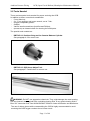
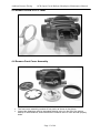
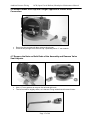
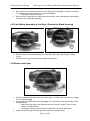
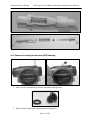
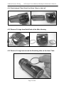
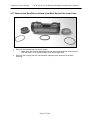
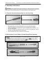
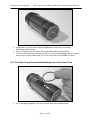
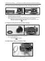
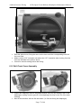
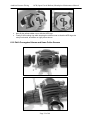
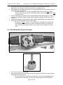
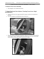
1
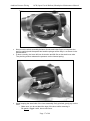
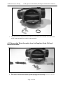
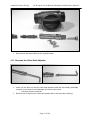
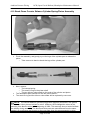
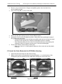
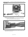
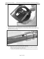
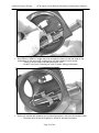
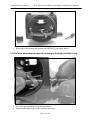
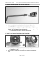
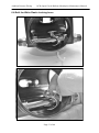
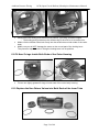
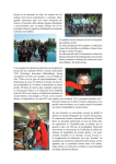
Ambient Pressure Diving OCB (Open Circuit Bailout) Mouthpiece Maintenance Manual OCB (Open Circuit Bailout) Mouthpiece Maintenance Manual Version 1.0 October 2009 Written by Tino de Rijk Page 1 of 44 Ambient Pressure Diving OCB (Open Circuit Bailout) Mouthpiece Maintenance Manual Table of Contents Revision history ......................................................................................... 4 1. Introduction ............................................................................................ 5 1.1 Servicing........................................................................................................ 5 1.2 Two modes .................................................................................................... 5 1.3 Patented Dual Valve Technology .................................................................. 5 1.4 Warranty ........................................................................................................ 6 1.5 Copyright and Applicable Law ....................................................................... 6 2. OCB Exploded Diagram and Parts List ................................................. 7 2.1 RB110 Main Assembly .................................................................................. 7 2.2 RB111 Dual Valve Assembly ......................................................................... 8 2.3 RB112 Front Cover Assembly ....................................................................... 9 3. Service Kit Contents and Special Tools .............................................. 10 3.1 Service Kit Contents .................................................................................... 10 3.2 Tools Needed .............................................................................................. 11 4. Disassembly Instructions ..................................................................... 12 4.1 Remove Medium Pressure (MP) Hose ........................................................ 12 4.2 Remove Hose Collar Screws and Corrugated Hoses .................................. 12 4.3 Remove Yellow OC/CC Lever ..................................................................... 13 4.4 Remove Front Cover Assembly ................................................................... 13 4.5 Remove White Plastic Locking Lever .......................................................... 14 4.6 Remove Blank End Cap and Plunger Opposite to the MP Hose Connection .......................................................................................................................... 15 4.7 Remove the Nuts on Both Ends of the Assembly and Remove Valve Seat Adjuster ............................................................................................................. 15 4.8 Push Whole Assembly to the Right (Outside the Black Housing) ................ 16 4.9 Remove the Lever ....................................................................................... 16 4.10 Remove the Whole Assembly from the Regulator Body, Pulling it from the Left Side ............................................................................................................ 18 4.11 Unscrew the Valve Seat Adjuster .............................................................. 19 4.12 Break Down Counter Balance Cylinder/Spring/Piston Assembly............... 20 4.13 Remove Locking Screw from OCB Housing .............................................. 21 4.14 Push Internal Tube Out of the Outer Tube, to the Left ............................... 22 4.15 Remove O-rings from Both Ends of the Main Housing .............................. 22 4.16 Remove O-ring from around the Breathing Hole on the Inner Tube .......... 22 4.17 Remove the Non-Return Valves from Both Ends of the Inner Tube .......... 23 5. Clean and Replace Service Parts ....................................................... 24 5.1 Ultrasonically Clean Deposits from all Metal Parts ...................................... 24 5.3 Replace all O-rings with New Ones from the Service Kit ............................. 24 6. Assembly Instructions .......................................................................... 25 6.1 Screw the Valve Seat Adjuster Back into the Valve Body ........................... 25 6.2 Re-Assemble Counter Balance Cylinder/Spring/Piston Assembly............... 25 6.3 Insert the Valve Body into the OCB Main Housing ...................................... 26 6.4 Refit Lever ................................................................................................... 27 6.5 Push the Assembly through the Housing to the Right to Refit O-ring .......... 31 6.6 Refit Valve Seat Adjuster into the Valve Body End...................................... 32 6.7 Refit 17 mm Nuts on Both Ends of the Valve Body ..................................... 32 Page 2 of 44 Ambient Pressure Diving OCB (Open Circuit Bailout) Mouthpiece Maintenance Manual 6.8 Refit the White Plastic Locking Lever .......................................................... 33 6.9 Fit New O-rings Inside Both Ends of the Outer Housing .............................. 34 6.10 Replace the Non Return Valves into Both Ends of the Inner Tube ............ 34 6.11 Fit a New O-ring Around the Breathing Hole in the Inner Tube ................. 35 6.12 Insert the Internal Tube Back into the Outer Housing, from the Left .......... 36 6.13 Replace Locking Screw into the Outer Housing ........................................ 36 6.14 Refit Yellow Lever on Left Side of Tube .................................................... 36 6.15 Refit Front Cover Assembly ....................................................................... 37 6.16 Refit Corrugated Hoses and Hose Collar Screws ...................................... 38 6.17 Refit Blank End Cap and Plunger .............................................................. 39 6.18 Refit MP Hose ........................................................................................... 40 7. Testing Instructions ............................................................................. 41 7.1 Check Airtight Sealing in OC Mode ............................................................. 41 7.2 Check Airtight Sealing in CC Mode ............................................................. 41 7.3 Check for Smooth Movement between OC and CC Mode .......................... 41 7.4 Remove Front Cover Assembly ................................................................... 42 7.5 Adjust Right-hand Valve Adjuster, Checking Correct Lever Height with RBTOOL15........................................................................................................ 42 7.6 Adjust Left-hand Valve Adjuster, Checking Correct Lever Height with RBTOOL15........................................................................................................ 43 7.7 Refit Front Cover Assembly ......................................................................... 44 7.8 Test for Leaks and Breathing Quality by Attaching the OCB with its MP Hose onto a 50 bar Oxygen-Compatible Clean Air Source ......................................... 44 7.9 Check Proper Breathing also in Right Hand Mode ...................................... 44 Page 3 of 44 Ambient Pressure Diving OCB (Open Circuit Bailout) Mouthpiece Maintenance Manual Revision history Date Oct 30, 2009 Version 1.0 Author Tino de Rijk Page 4 of 44 Comments Final version, approved by APD Ambient Pressure Diving OCB (Open Circuit Bailout) Mouthpiece Maintenance Manual 1. Introduction 1.1 Servicing Before servicing this OCB mouthpiece, you must receive instruction and certification in the maintenance of this OCB by the Ambient Pressure Diving factory. Without the correct training it is possible to configure the OCB incorrectly in an unsafe manner. Factory / Dealer prescribed service for this OCB mouthpiece is recommended at least once annually. The Inspiration, Evolution and Evolution+ closed circuit rebreathers’ CE certification to EN14143 is unaffected by the addition of this OCB mouthpiece. This OCB mouthpiece meets the requirements of the Personal Protective Equipment Directive 89/686/EEC – CE certification when fitted to a first stage regulator conforming to EN250 or EN13949 and to an Ambient Pressure Diving rebreather. WARNING: when servicing the OCB, it is VERY important that all parts that may suffer wear and tear get replaced. It is also very important that the correct special tools are used to avoid damaging any part of the OCB in the disassembly and assembly process. Please don’t try to save money by re-using parts that really should be replaced during a proper servicing action. The numbers between brackets after the part names in the disassembly and assembly chapters correspond to the sequence numbers in the diagrams in chapter 2. 1.2 Two modes The OCB Mouthpiece has 2 Modes: - CC: Closed Circuit rebreather diving position. - OC: Open Circuit diving position. This is the BAIL-OUT mode. The two modes are selected by rotating the lever (M16) forwards or backwards, which in turn rotates the internal components within the main body. The Rebreather mode is activated by rotating the lever to the backward position where the lever is in line with the mouthpiece. The Open circuit mode is activated when the lever is rotated forward to the ‘up’ position. The lever is best operated by the diver resting his right hand on top of the corrugated hose and placing an extended thumb between the two lugs of the lever. 1.3 Patented Dual Valve Technology The OCB Mouthpiece utilises ‘AP’s new patented Dual Valve Technology. This new demand valve enables the diver to quickly and easily change the medium pressure (7 to 14 bar) supply hose routing from left to the right hand side, without the need for major disassembly, adjustment or any special tools. Page 5 of 44 Ambient Pressure Diving OCB (Open Circuit Bailout) Mouthpiece Maintenance Manual The Dual Valve can be switched between the left and right hand side in 5 simple steps: 1. Turn the gas off and purge. 2. Unscrew (anti-clockwise) the supply hose (M1) and then the 9/16” UNF blanking cap (V7) from the opposite end until the threads disengage, then pull withdrawing the plunger (V6). If a tool needs to be used to undo these fittings, protect the plastic moulding by preventing the Dual Valve Body from rotating by using two 17mm spanners, one on the adjacent hexagon nut. 3. Fully screw the plunger back into the blanking cap until the threads disengage and then gently slide the plunger into the opposite side of the dual valve. 4. Screw the blanking cap on until it is tight against the shoulder, covering the thread. You should be able to do this up without tools. If resistance is met, you need to ensure the plunger is fully into the blanking cap and the threads are clean and sufficiently lubricated with oxygen compatible grease. While finger-tight is sufficient, it is prudent to just nip it up lightly using two 17mm spanners. 5. Reconnect the medium pressure supply hose. Turn the gas on slowly and test for leaks and breathing performance prior to diving. WARNING: When switching the valve from left to right hand side hose routing, use two 17mm spanners, one on the hexagon of the blanking cap or hose and the other on the adjacent hexagon immediately next to the valve body. Using just one spanner on the blanking cap or hose may damage the valve body. WARNING: If additional components are used in the medium pressure gas supply, for instance a Gas Connection System or Gas Switching block, it is important to realise that these may interfere with the gas flow to the OCB and degrade the breathing performance, preventing the OCB from supplying sufficient gas to a hard working diver at depth. Additionally, if they interrupt the gas supply the OCB may be critically damaged on descents. 1.4 Warranty This OCB mouthpiece is covered by Ambient Pressure Diving’s 2 year warranty against defects in materials or workmanship. This warranty is only extended to the original purchaser, and is not transferable. For more information, be sure to read the warranty section of the user manual, and the purchaser should save the sales receipt. A copy of the receipt must be presented whenever obtaining warranty service. 1.5 Copyright and Applicable Law This Maintenance Manual is copyrighted, all rights reserved. It may not, in whole or in part, be copied, photocopied, reproduced, translated, or reduced to any electronic medium (including the Internet) or machine readable form without prior consent in writing from Ambient Pressure Diving. All products are sold on the strict understanding that only English Law applies in cases of warranty claims and product liability, regardless of where the equipment is purchased or used. Should a claim be made then the venue for this would be in Truro, England. © 2009 Ambient Pressure Diving OCB Maintenance Manual Page 6 of 44 Ambient Pressure Diving OCB (Open Circuit Bailout) Mouthpiece Maintenance Manual 2. OCB Exploded Diagram and Parts List 2.1 RB110 Main Assembly NUMBER DESCRIPTION PART NUMBER QUANTITY M1 Inflator Hose Assembly AP300 1 M2 Dual Valve Assembly RB111 1 M3 Front cover Assembly RB112 1 M4 Location Screw RB114_1 1 M5 Inner Tube RB116 1 M6 Valve Holder RH RB02_04 1 M7 Valve Holder LH RB02_03 1 M8 O Ring BS010 N70 1 M9 Non-return O Ring BS029 N70 2 M10 Mouthpiece Seal BS125 N70 1 M11 Inner O Ring BS48x2.5 N70 2 M12 Main Outer RB115 1 M13 Ty-Rap AP21 1 M14 Mouthpiece AP16 1 M15 One Way Valve RB02_05 2 M16 Lever RB116_1 1 M17 Exhale Hose Assembly RB07_03 1 Page 7 of 44 Ambient Pressure Diving NUMBER OCB (Open Circuit Bailout) Mouthpiece Maintenance Manual DESCRIPTION PART NUMBER QUANTITY M18 Hose Collar Screw SC102 2 M19 Inhale Hose Assembly RB07_04 1 PART NUMBER QUANTITY 2.2 RB111 Dual Valve Assembly NUMBER DESCRIPTION V1 Silicone Valve Seat AP100_23 2 V2 O Ring BS2.5x1 N70 1 V3 O Ring BS010 N70 3 V4 O Ring BS14.5x2.5 N70 2 V5 Valve Body RB111_1 1 V6 Plunger RB111_10 1 V7 9/16” Blanking Plug RB111_11 1 V8 Locking Lever RB111_12 1 V9 Counter Balance Piston RB111_2 1 V10 Counter Balance Cylinder RB111_3 1 V11 Dual Valve Spring RB111_5 1 V12 Lever RB111_6 1 V13 Valve body End RB111_7 1 V14 Valve Locking Nut RB111_8 1 V15 Valve Seat Adjuster RB111_9 2 Page 8 of 44 Ambient Pressure Diving OCB (Open Circuit Bailout) Mouthpiece Maintenance Manual 2.3 RB112 Front Cover Assembly NUMBER DESCRIPTION PART NUMBER QUANTITY F1 Diaphragm Lever Pad RB112_6 1 F2 Locking Ring RB112_1 1 F3 Diaphragm RB112_5 1 F4 Skid Disk RB112_3 1 F5 Exhaust Diaphragm RB112_4 1 F6 Rubber Cover RB112_2 1 Page 9 of 44 Ambient Pressure Diving OCB (Open Circuit Bailout) Mouthpiece Maintenance Manual 3. Service Kit Contents and Special Tools 3.1 Service Kit Contents WARNING: When replacing O-rings, next to the size, the hardness of the O-rings (declared in degrees Shore, and indicated by the suffixes N70 and N90) is ESSENTIAL for proper operation. The N70 or N90 hardness of the O-rings is deliberately selected by Ambient Pressure Diving. If you choose to select your O-rings to come from another source than Ambient Pressure Diving, make sure you select the right type in size AND hardness. When servicing the OCB, the following parts need to be replaced: NUMBER DESCRIPTION PART NUMBER M8 O Ring on Location Screw BS010 N70 1 M9 Non-return Holder Seals BS029 N70 2 M10 Mouthpiece Seal on Inner Tube BS125 N70 1 M11 Inner O Rings on inside of Main Body Silicone Valve Seats BS48x2.5 N70 2 AP100_23 2 O Ring on Counter Balance Piston O Rings on Valve Seat Adjusters and Plunger O Rings on Regulator Valve Body BS2.5 x 1 N70 1 BS010 N70 3 BS14.5x2.5 N70 2 V1 V2 V3 V4 QUANTITY These items to be replaced as required: M6 + M15 M7 + M15 F3 Non-return Valve Holder RH + One Way Valve Non-return Valve Holder LH + One Way Valve Diaphragm Page 10 of 44 RB02_04 + RB02_05 1 RB02_03 + RB02_05 1 RB112_5 1 Ambient Pressure Diving OCB (Open Circuit Bailout) Mouthpiece Maintenance Manual 3.2 Tools Needed There are two special tools needed for proper servicing the OCB. In addition to these, normal tools needed are: - 5 mm Allen key; - 2 x 17 mm spanner and torque wrench, set to 7 Nm; - Oxygen-compatible grease; - Scalpel; - Various small screwdrivers (both flat and Phillips); - (access to) an ultrasonic bath for cleaning the metal parts. The special tools needed are: - RBTOOL13: Position-fixing tool for Counter Balance Cylinder. See paragraph 4.9 for correct use. - RBTOOL15: OCB Lever Adjust Tool. See paragraph 7.5 and further for correct use. WARNING: Do NOT use aggressive chemicals. They might damage the metal coating. Use an ultrasonic cleaning bath with a suitable cleaning fluid. A very good cleaning fluid is Biox “O2” immersion fluid. See WWW.BIOXINT.COM for further information and distributors. The use of rubber gloves while re-assembling the OCB is highly recommended to avoid rendering the OCB oxygen unclean due to human touch. Page 11 of 44 Ambient Pressure Diving OCB (Open Circuit Bailout) Mouthpiece Maintenance Manual 4. Disassembly Instructions 4.1 Remove Medium Pressure (MP) Hose Remove the MP hose Remove the O-ring in the hose and replace with a new one 4.2 Remove Hose Collar Screws and Corrugated Hoses Mark the position of the stainless steel screws before removing Remove the two S/S screws (one in each hose collar) Unscrew both corrugated hoses Visually inspect corrugated hoses for wear and tear while stretching them a bit Inspect the sealing O-rings inside the hose collars. If damaged or flat, replace them. Page 12 of 44 Ambient Pressure Diving OCB (Open Circuit Bailout) Mouthpiece Maintenance Manual 4.3 Remove Yellow OC/CC Lever 4.4 Remove Front Cover Assembly The front cover assembly consists of four parts, as shown in the picture. Inspect the diaphragm with its integrated exhaust valve (on the left of the picture above) for wear and tear, and check that the exhaust valve is clean and still properly seals. Page 13 of 44 Ambient Pressure Diving OCB (Open Circuit Bailout) Mouthpiece Maintenance Manual 4.5 Remove White Plastic Locking Lever Gently pry the locking lever out of its position, using a very small screwdriver (e.g. a watch repair screwdriver as shown in the picture). Make sure you do NOT damage the small location cams on the curved part of the locking lever. They have an important role in fixing the locking lever into its position. Page 14 of 44 Ambient Pressure Diving OCB (Open Circuit Bailout) Mouthpiece Maintenance Manual 4.6 Remove Blank End Cap and Plunger Opposite to the MP Hose Connection Removing the end cap will also remove the plunger Unscrew the plunger from the end cap. Optionally use a 17 mm wrench. 4.7 Remove the Nuts on Both Ends of the Assembly and Remove Valve Seat Adjuster Use a 17 mm spanner to remove the left and right nuts The left nut will be slightly stiffer, as it has an O-ring inside that will cause friction Page 15 of 44 Ambient Pressure Diving OCB (Open Circuit Bailout) Mouthpiece Maintenance Manual Next insert a 5 mm Allen key into the valve body end, preferably one with a round top to avoid damage, and unscrew the valve seat adjuster o Unscrew counter-clockwise Remove the O-rings from the valve body end and the valve seat adjuster and replace them with new ones after cleaning. 4.8 Push Whole Assembly to the Right (Outside the Black Housing) Push the whole internal assembly out of the black housing, exposing the sealing O-ring Remove the O-ring, as shown in the right picture above. 4.9 Remove the Lever Push the internal assembly back into the housing, to make more room for your fingers for the following steps Use special tool RBTOOL13 (see paragraph 3.2) and insert it into the left side of the regulator body. o Make sure the slots in the special tool hook onto the “wings” of the counter balance cylinder inside. o If inserted correctly, the special tool only sticks out a few millimetres. Insert the steel plunger into the opposite end of the regulator body. Page 16 of 44 Ambient Pressure Diving OCB (Open Circuit Bailout) Mouthpiece Maintenance Manual Now pinch the whole assembly between thumb and index finger to compress the spring, pushing both the special tool and the plunger all the way in, as shown in the picture above. If done correctly, the lever will lose its tension and fall flat on the steel inner tube. The pinching motion releases the pressure on the internal spring. While keeping the steel tube of the inner assembly firmly pinched, gently pry out the lever. o Make sure you do not bend the legs of the lever while removing it. Be gentle; wiggle it a bit, do not use force. Page 17 of 44 Ambient Pressure Diving OCB (Open Circuit Bailout) Mouthpiece Maintenance Manual The picture above shows the removed lever, as well as one of holes in the steel tube of the inner assembly from which it was removed. 4.10 Remove the Whole Assembly from the Regulator Body, Pulling it from the Left Side First remove the special tool and plunger that were used for compressing the spring. Next remove the counter balance cylinder/spring/piston assembly. Page 18 of 44 Ambient Pressure Diving OCB (Open Circuit Bailout) Mouthpiece Maintenance Manual Next remove the steel tube from the regulator body. 4.11 Unscrew the Valve Seat Adjuster Insert a 5 mm Allen key into the valve seat adjuster inside the valve body, preferably one with a round top to avoid damage, and remove the insert o Unscrew counter-clockwise Remove the O-ring from the insert and replace with a new one after cleaning. Page 19 of 44 Ambient Pressure Diving OCB (Open Circuit Bailout) Mouthpiece Maintenance Manual 4.12 Break Down Counter Balance Cylinder/Spring/Piston Assembly Pinch the assembly, and gently pry out the legs of the cylinder-part to release the piston. o Take care not to bend or break the legs of the cylinder part. Next, remove: o The internal spring o The small O-ring on the piston shaft o The two silicone valve seats on the ends of the cylinder and piston The assembled parts should look like the picture above. The small O-ring and the silicone valve seats will be replaced by new ones. NOTE: The counter balance cylinder/spring/piston assembly as shown in the picture above and on other pictures is black in colour. However, APD changed the colour of the assembly from black to white in the beginning of 2009. This was only done to better facilitate the visibility during assembly. The black and white parts are manufactured from the same material. As a reference the pictures on the next page show the same assembly in white. Page 20 of 44 Ambient Pressure Diving OCB (Open Circuit Bailout) Mouthpiece Maintenance Manual 4.13 Remove Locking Screw from OCB Housing Use a 3.5 mm screwdriver to remove the plastic locking screw Remove the O-ring from the black plastic locking screw Page 21 of 44 Ambient Pressure Diving OCB (Open Circuit Bailout) Mouthpiece Maintenance Manual 4.14 Push Internal Tube Out of the Outer Tube, to the Left 4.15 Remove O-rings from Both Ends of the Main Housing 4.16 Remove O-ring from around the Breathing Hole on the Inner Tube Page 22 of 44 Ambient Pressure Diving OCB (Open Circuit Bailout) Mouthpiece Maintenance Manual 4.17 Remove the Non-Return Valves from Both Ends of the Inner Tube Remove and inspect the non return valves o Make sure the silicone diaphragms do not show wear and tear, and inspect if they still seal o.k. by gently trying to suck air through them Remove the O-rings from the valve bodies. Replace them with new ones after cleaning. Page 23 of 44 Ambient Pressure Diving OCB (Open Circuit Bailout) Mouthpiece Maintenance Manual 5. Clean and Replace Service Parts The servicing of the OCB stage contains 3 “action groups”: 1. Removing and binning all parts that should be replaced. These are all O-rings and the silicone valve seats. 2. Ultrasonic-cleaning of all disassembled metal parts. This is especially important for the OCB to stay oxygen-clean. 3. Lightly grease new parts, fit them, and re-assemble the OCB with the correct tools and the correct torques (7 Nm). Use Oxygen-compatible grease, and avoiding contaminating the metal parts after cleaning. The use of rubber gloves while re-assembling the OCB is recommended to avoid rendering the OCB unclean due to human touch. As described in chapter 3.1, the following parts need to be replaced when servicing the OCB: NUMBER DESCRIPTION PART NUMBER M8 O Ring on Location Screw BS010 N70 1 M9 Non Return Valve Holder Seals BS029 N70 2 M10 Mouthpiece Seal on Inner Tube BS125 N70 1 M11 Inner O Rings on inside of Main Outer Silicone Valve Seats BS48x2.5 N70 2 AP100_23 2 O Ring on Counter Balance Piston O Rings on Valve Seat Adjusters and Plunger O Rings on Regulator Valve Body BS2.5x1 N70 1 BS010 N70 3 BS14.5x2.5 N70 2 V1 V2 V3 V4 QUANTITY 5.1 Ultrasonically Clean Deposits from all Metal Parts Clean deposits from all metal parts, like chalk and salt. WARNING: Do NOT use aggressive chemicals. They might damage the metal coating. Use an ultrasonic cleaning bath with a suitable cleaning fluid instead. A good cleaning fluid is Biox “O2” immersion fluid. See WWW.BIOXINT.COM for further information and distributors. 5.3 Replace all O-rings with New Ones from the Service Kit - WARNING: Make sure you use only Oxygen-compatible grease. Also make sure you only use Oxygen-clean and Oxygen-compatible replacement parts. All APD-supplied O-rings in the service kit are made from Nitrile and as such are Oxygen compatible. However, they still need to stay or be made Oxygen-clean. Last but not least: avoid touching Oxygen-clean parts after cleaning with your bare hands. Human body sweat and grease is not Oxygen-compatible. So use (e.g. surgical) rubber gloves when re-assembling the OCB. For photographic clarity no rubber gloves are worn on the photo’s below. Page 24 of 44 Ambient Pressure Diving OCB (Open Circuit Bailout) Mouthpiece Maintenance Manual 6. Assembly Instructions WARNING: When assembling the OCB, preferably use rubber gloves to avoid polluting it while assembling, rendering it not Oxygen-clean anymore. As this part may be exposed to high Oxygen content breathing gasses it is highly preferable it stays Oxygen-clean. 6.1 Screw the Valve Seat Adjuster Back into the Valve Body Before assembly check the sealing surface of the valve seat adjuster with a magnifying eyeglass to check the surface for any imperfections or damage. Smear a new BS010 O-ring lightly with oxygen-compatible grease and place it onto the valve seat adjuster. Using a 5 mm Allen key, preferably one with a round top to avoid damage, carefully screw the valve seat adjuster into the valve body. Screw clockwise all the way in, and then 2 full turns back. 6.2 Re-Assemble Counter Balance Cylinder/Spring/Piston Assembly NOTE: See also note in paragraph 4.12: the counter balance cylinder/spring/piston assembly as shown in the picture above and on other pictures is black in colour. However, APD changed the colour of the assembly from black to white in the beginning of 2009. So in the field you can find either black or white assemblies, depending on the age of the OCB. They are both manufactured from the same material. Page 25 of 44 Ambient Pressure Diving OCB (Open Circuit Bailout) Mouthpiece Maintenance Manual Smear a very small amount of Oxygen-compatible grease onto the shaft of the counter balance piston. Fit a new O-ring (BS_2_6x1) on the shaft. Place the dual valve spring onto the counter balance piston. Assemble it into the counter balance cylinder, taking care when pushing the ends of the cylinder over the piston. o Only bend the ends out as minimal as possible; take care not to bend or break the legs of the cylinder part, rendering it damaged and thus unusable. o After assembly make sure the valve is running smoothly by compressing and releasing it with your fingers several times. It should not disengage. Fit new clear silicone valve seats on both ends. o Make sure there is no visible gap left between silicon seat end and the plastic housing. 6.3 Insert the Valve Body into the OCB Main Housing Insert the steel valve body into the main housing. Make sure the hole in the assembly is facing backwards, i.e. in the direction of the mouthpiece (the hole should not be visible when looking into it from the front). CORRECT: hole is NOT visible WRONG: hole is visible Page 26 of 44 Ambient Pressure Diving OCB (Open Circuit Bailout) Mouthpiece Maintenance Manual 6.4 Refit Lever Shown above are the position-fixing tool, the counter balance cylinder/spring/piston assembly, the lever and the steel piston. o The piston is used here again to facilitate compressing the counter balance cylinder, using a pinching motion as shown further below. Insert special position-fixing tool (RBTOOL13) onto the “wings” of the plastic counter balance cylinder, as shown above. Page 27 of 44 Ambient Pressure Diving OCB (Open Circuit Bailout) Mouthpiece Maintenance Manual RBTOOL13 has a small notch as indicated in the left side picture above. This notch should be aligned with the legs of the cylinder part of the counter balance cylinder/spring/piston assembly, as indicated in the right side picture above, i.e. the legs should be facing up and down, not left and right. o For clarity reasons, the white version of the assembly is used in the picture above. As indicated before, the black and white versions are alike. Make sure the notch in RBTOOL13 is always pointing up when inserting the assembly into the valve body. Using the position-fixing tool, insert the counter balance cylinder into the valve body; the spring-fitted piston end side goes in first. o Remember keeping the notch in the special tool, and thus the legs of the assembly, facing up. Next insert the steel plunger into the right side of the valve body. Page 28 of 44 Ambient Pressure Diving OCB (Open Circuit Bailout) Mouthpiece Maintenance Manual Compress the valve in one hand between thumb and fore-finger as shown above, applying pressure on both the special tool on the left side and the steel plunger on the other side of the valve body. By compressing, the holes are freed up to take the lever. o Make sure that the cylinder and piston components are properly orientated with the square opening in the valve body. o The above slot should be visible when pinching the plunger and special tool. Page 29 of 44 Ambient Pressure Diving OCB (Open Circuit Bailout) Mouthpiece Maintenance Manual Now REALLY GENTLY wiggle the lever and place it back into the two slots on top and bottom of the valve body, making sure you don’t bend it out too much: o Twist it in on an angle, first fitting the upper “foot” o Do NOT use force, it should just “click” in place, falling in the holes. When you release the pressure by not pinching anymore, the lever should erect itself. o Press the lever a few times gently to check for smooth movement. Page 30 of 44 Ambient Pressure Diving OCB (Open Circuit Bailout) Mouthpiece Maintenance Manual Next remove the plunger and special tool RBTOOL13, as shown above. 6.5 Push the Assembly through the Housing to the Right to Refit O-ring Fit a new lightly greased O-ring into the groove Push the assembly back in until it locks on the O-ring Page 31 of 44 Ambient Pressure Diving OCB (Open Circuit Bailout) Mouthpiece Maintenance Manual 6.6 Refit Valve Seat Adjuster into the Valve Body End Before assembly check the sealing surface of the valve seat adjuster with a magnifying eyeglass to check the surface for any imperfections or damage. Smear a new BS010 O-ring lightly with oxygen-compatible grease and place it onto the valve seat adjuster. Using a 5 mm Allen key, preferably one with a round top to avoid damage, carefully screw the valve seat adjuster into the valve body end. o Screw clockwise all the way in, and then 2 full turns back. 6.7 Refit 17 mm Nuts on Both Ends of the Valve Body Fit a new lightly greased O-ring onto the valve body end (see left picture) Use a 17 mm spanner to refit the left and right nuts o Use a torque of 7 Nm The left nut will be slightly stiffer, as it has an O-ring inside that will cause some friction Page 32 of 44 Ambient Pressure Diving OCB (Open Circuit Bailout) Mouthpiece Maintenance Manual 6.8 Refit the White Plastic Locking Lever Page 33 of 44 Ambient Pressure Diving OCB (Open Circuit Bailout) Mouthpiece Maintenance Manual Gently place the locking lever back into its position, just using your bare fingers, o Optionally gently push down the inserted leg of the lever a bit to make room Make sure the location cams lock firmly into the small holes on both sides of the valve body Make sure you do NOT damage the cams on the curved part of the locking lever. They have an important role in fixing the locking lever into its position. 6.9 Fit New O-rings Inside Both Ends of the Outer Housing Fit two new lightly greased O-rings in both ends of the outer body housing 6.10 Replace the Non Return Valves into Both Ends of the Inner Tube Page 34 of 44 Ambient Pressure Diving OCB (Open Circuit Bailout) Mouthpiece Maintenance Manual Inspect the non-return valves and the diaphragms inside them for damage. If damaged, replace them. Fit new O-rings to the non return valve bodies after lightly greasing them The blue valve body has a groove that will fit over the small upstand inside the inhale side of the inner tube. Make sure you fit it on the correct side. NEVER use force. 6.11 Fit a New O-ring Around the Breathing Hole in the Inner Tube Fit a new lightly greased O-ring in the groove around the breathing hole Page 35 of 44 Ambient Pressure Diving OCB (Open Circuit Bailout) Mouthpiece Maintenance Manual 6.12 Insert the Internal Tube Back into the Outer Housing, from the Left Slightly grease the inner tube before fitting it back, especially the ends where they will touch the O-rings in the outer tube Make a slight rotating movement while inserting it into the outer housing, making sure the breathing hole on the inner tube points in the direction of the mouthpiece o Make sure you do not jam either the O-ring around the breathing hole or the ones in the outer tube. Do NOT use force! 6.13 Replace Locking Screw into the Outer Housing Fit a new lightly greased O-ring on the locking screw Use a 3.5 mm screwdriver o Take care to NOT over tighten 6.14 Refit Yellow Lever on Left Side of Tube Page 36 of 44 Ambient Pressure Diving OCB (Open Circuit Bailout) Mouthpiece Maintenance Manual Refit the yellow lever, fitting the cams on the lever onto the corresponding holes on the inner tube. Make sure the “OC” inscription sits above the “CC” inscription when looking from the front, as indicated in the picture above Check for smooth rotating action after fitting 6.15 Refit Front Cover Assembly Inspect the diaphragm with its integrated exhaust valve for any damage, then fit the diaphragm, making sure the groove in the diaphragm fits fully on the rim of the outer housing Next fit the skid disk, with the flat side down (i.e. flat side facing the diaphragm) Page 37 of 44 Ambient Pressure Diving OCB (Open Circuit Bailout) Mouthpiece Maintenance Manual Next fit the yellow rubber cover with the APD logo Finally fit the locking ring while keeping the rubber cover so that the APD logo sits nicely horizontal, as shown on right picture above 6.16 Refit Corrugated Hoses and Hose Collar Screws Page 38 of 44 Ambient Pressure Diving OCB (Open Circuit Bailout) Mouthpiece Maintenance Manual Just to be sure, once more inspect the non-return valves and their internal diaphragms for damage or dirt before fitting the corrugated hoses Next screw the corrugated hoses back on, noting the position of the holes for the two small S/S hose collar screws o Use “blue on blue”, i.e. fit the corrugated inhale hose with the blue rubber marker rings onto the left side of the OCB, which is the side fitted with the blue non-return valve Use the markings you made previously during disassembly (paragraph 4.2) when you removed the screws to find the same position again for taking the S/S hose collar screws Inspect the sealing O-rings inside the hose collars. If damaged or flat, replace them Screw the S/S screws back into the collars again o Be gentle; do NOT use force: it is quite easy to overtighten the screws and thus damage the thread in the collars. Remember that the only function of these screws is to prevent rotation of the collars on the thread in the inner tube. 6.17 Refit Blank End Cap and Plunger Fit a new O-ring onto the plunger. Next screw the plunger all the way through the thread in the blank end cap so that it disengages from the thread. o You can check this by pulling on the plunger: if it has fully disengaged from the thread in the end cap, you can move the plunger a bit in all directions. Page 39 of 44 Ambient Pressure Diving OCB (Open Circuit Bailout) Mouthpiece Maintenance Manual Next screw the blank end cap with the plunger inside, onto the opposite end to where you will be attaching the MP hose. o Fitting it hand-tight should be enough, but just nip it up with a 17 mm spanner to avoid accidental loosening. 6.18 Refit MP Hose Replace the O-ring with a lightly greased new one Screw the hose back on, finger-tight Page 40 of 44 Ambient Pressure Diving OCB (Open Circuit Bailout) Mouthpiece Maintenance Manual 7. Testing Instructions 7.1 Check Airtight Sealing in OC Mode Switch the OCB to OC mode, using the yellow lever Either: o Attach the MP hose and close up the 1st stage end of the hose by either attaching it to a 1st stage, or (when not connected to a 1st stage) simply block the end of the hose by sealing off with your finger o If attached to a 1st stage, make sure that stage is connected to a closed cylinder, as otherwise it is still possible to suck air through the 1st stage when it is unconnected Or: o Detach the MP hose, and block off the now exposed valve body end with your finger Put the mouthpiece in your mouth and try to suck air in: this should not be possible. Test the exhaust valve by blowing out through the mouthpiece: this should go without noticeable effort or delays. Repeat the above inhale and exhale actions a few times to make sure no leaks exist in the OC parts. If leaks are found (i.e. it is possible to continue to suck in air), inspect: o the diaphragm; o the exhaust valve; o the O-ring on the inner tube around the mouthpiece; o the O-ring on the small location screw on top of the main house. 7.2 Check Airtight Sealing in CC Mode Switch the OCB to CC mode, using the yellow lever Hold the inhale corrugated hose (with the blue rings) against your cheek, and try to suck air in through the mouthpiece. The corrugated hose should now build up a bit of vacuum, and should “stick” to your cheek when you take the mouthpiece out of your mouth. o This is due to the non-return valve functioning well Any further attempts to suck in more air should not work. o If the hose does stick to your cheek, but it is nevertheless possible to continue to suck in air, inspect: the mouthpiece and its ty-rap for damage; the O-ring on the inner tube around the mouthpiece; the O-rings in the collars of the corrugated hoses; the O-ring on the small location screw on top of the main house. Try to blow into the end exhale corrugated hose. This should not be possible. Hold the exhale corrugated hose against your cheek and try to blow through the mouthpiece. This should not be possible. 7.3 Check for Smooth Movement between OC and CC Mode Move the yellow lever a few times to verify proper and smooth switching operation between the OC and CC modes Page 41 of 44 Ambient Pressure Diving o OCB (Open Circuit Bailout) Mouthpiece Maintenance Manual Combine this with the airtight tests of paragraphs 7.1 and 7.2 above. 7.4 Remove Front Cover Assembly See paragraph 4.4 for detailed instructions. 7.5 Adjust Right-hand Valve Adjuster, Checking Correct Lever Height with RBTOOL15 Attach the MP hose to an oxygen-clean MP air supply, and then to the right side of the OCB. Turn the air supply on and depress the lever a few times. Using the adjuster tool RBTOOL15 as shown, simply roll it over the lever to check the correct height. The thin outsides of RBTOOL15 should rest on the rim of the housing, while the thicker center part is used to check the lever height. Page 42 of 44 Ambient Pressure Diving OCB (Open Circuit Bailout) Mouthpiece Maintenance Manual The thicker center part of RBTOOL15 should just touch the lever. Check for proper position of the lever by gently pushing it down a few times by hand, followed by re-checking the correct height with RBTOOL15. If it is not correct turn off the air supply, release the pressure by depressing the lever and remove the MP hose. Using a 5 mm Allen key (preferably one with a round top) insert it into the now exposed valve seat adjuster. o Rotate the Allen key anti-clockwise to raise the lever and clockwise to lower it. o You can optionally use RBTOOL15 as a reference to check the amount of change in height. Typically use only 1/8 turns at a time. Re-attach the MP hose, turn the air back on and re-check the height of the lever. Repeat the steps above until the lever height is correct. 7.6 Adjust Left-hand Valve Adjuster, Checking Correct Lever Height with RBTOOL15 After adjusting the right hand side of the OCB, swap the blank end cap with its plunger inside over from the left side of the valve body to the right side. o See paragraph 6.17 for detailed instructions. Page 43 of 44 Ambient Pressure Diving OCB (Open Circuit Bailout) Mouthpiece Maintenance Manual o Make sure you screw the plunger again in all the way in the end cap so that is disengages again from the thread before fitting it. Repeat the height adjustment setting steps as described above in paragraph 7.5 7.7 Refit Front Cover Assembly See paragraph 6.15 for detailed instructions. 7.8 Test for Leaks and Breathing Quality by Attaching the OCB with its MP Hose onto a 50 bar Oxygen-Compatible Clean Air Source After adjusting both valve adjusters and refitting the front cover assembly, repeat the checks for airtight sealing and smooth lever operation as described in paragraphs 7.1, 7.2 and 7.3 above. o Especially check for free-flow by pressing the purge button. Re-attach the MP hose as described in paragraph 6.18 to the left hand side of the OCB, and connect it to an oxygen-clean medium pressure air source. The ideal medium pressure for the OCB is 9.5 bar. However, the OCB is a balanced design and will function within a medium pressure range of between 8 to 13 bar. We recommend however testing and adjusting, and in fact also using the OCB with an intermediate pressure of 9.5 bar. Slowly open the tank the valve, while keeping the purge button (yellow front cover) of the second stage pressed. Now release the purge button from the OCB and listen for any leaks. Next submerge the OCB in water to check for any leaks. Breathe in very slowly and softly, but also breathe in hard and fast a few times. The breathing should be smooth, without noticeable resistance or delays. 7.9 Check Proper Breathing also in Right Hand Mode Swap over the MP hose from the left to the right hand side of the OCB. Swap over the blank end cap with its plunger inside from the right to the left hand side of the OCB. o See paragraphs 6.17 and 6.18 for detailed instructions. Repeat the test steps as described in paragraph 7.8 above. NOTE: The newly fitted silicone valve seats (see paragraph 6.3) should ideally be given some time to “sink in” against the sharp edges of the valve seats, under the pressure of the internal spring. This does not just apply to the OCB, but to ANY regulator that has new valve seats fitted. The “sinking in” may cause a tiny fraction of extra room that may just be enough to cause free-flowing or a small leak after a day or so, if the tuning of the OCB is done directly after replacing the seats as part of the service. So if at all possible, perform the servicing of the OCB on day one, then let it rest overnight, and do the tuning and adjustment on the next day. Page 44 of 44