1
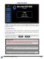
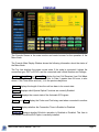
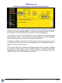
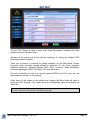
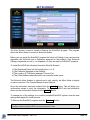
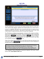
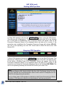
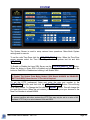
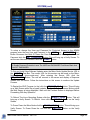
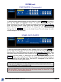
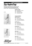
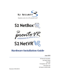
ECHO-IRLP Micro-Node
USER’S MANUAL
MICRO-NODE
World’s Smallest Plug & Play IRLP / EchoLink Embedded Solutions
SOFTWARE VERSION
1.62
Micro-Node International, Inc. - Henderson, Nevada
Micro-Node User's Manual - Ver 1.62
Page 1
ADMIN PACKAGE
‘ADMIN’ is the Micro-Node custom web browser based package that is used to
program and operate the Micro-Node. To access ADMIN point a JavaScript Enabled
browser to the URL:
your-ip-address/admin
This will bring up the ADMIN Opening Screen. It displays the units assigned Callsign
and IRLP Node Number. It also displays the units EchoLink Number if EchoIRLP has
been activated on the unit.
The buttons in the left panel of the Admin screen are used to select the various Admin
setup and control sections. The Menu A and Menu B buttons select the two
available menu control banks.
IMPORTANT NOTE:
The ADMIN program can be Password Protected. This protection is setup through the
System Screen. It is Strongly Recommended that Password Protection be used if the
unit’s HTTP Server Port is exposed to the Wide Area Network (Internet).
Note:
ADMIN can be brought up in a browser Pop-Up window with minimum space used for
browser controls. To activate this Pop-Up window Double Click on the Picture Of The World
on the opening screen.
Note:
A special console control screen for use with the Nokia N800/810 and other PDA’s can be
displayed by clicking the node information box in the upper left corner of the display.
Micro-Node User's Manual - Ver 1.62
Page 2
CONSOLE
The Console Screen is the main monitor and control screen for the operation of the
Micro-Node.
The Console Main Display Window shows the following information about the status of
the Micro-Node.
The Top Line displays the nodes current state. If the node is connected it shows the
connection type, IRLP or ECHO, and the connected node’s Node Number and Callsign.
Last_In , Last_Out and Last_CW display the Last Call Received, Last Call Made
and Last Call Waiting. The connection Time, or Date if greater than 24 hours, is also
shown. If the Time shows a minus (-) it is the previous days time.
Interval displays the length of time the unit has been in its current state.
Options displays which Special Option Functions are currently Enabled.
ID Status displays the current state of the Automatic ID Program.
Codec and Port display the Codec and Port being used when connected to another
node.
TimeOut displays whether the Connection Timer is Enabled or Disabled.
EchoLink displays whether EchoLink operation is Enabled or Disabled. This Item is
only shown if the EchoIRLP Option is currently installed.
Micro-Node User's Manual - Ver 1.62
Page 3
The lower Window in the display shows the command response information returned
from the last command sent from the console.
The Indicators to the left of the main window show the states of the units various Inputs
and Outputs.
The Buttons below the main display window are used to send commands and control
various functions on the Micro-Node. A detailed description of these buttons and their
functions plus other command control options follows.
Note:
In operation it should be noted that depending on the state of the node, various buttons and
options are disabled. For example if the node were connected, any button or option that
would attempt to make a connection would be disabled while the End Call button would be
enabled.
Micro-Node User's Manual - Ver 1.62
Page 4
CONSOLE (cont)
Outputs, Last Reconnect, Connect Timer, EchoLink
Operation of the Fan and Aux outputs of the unit can be controlled by moving the
mouse cursor over the desired Indicator. At that time the indicator will show a 0 and 1
box. Click the 0 to force the Output Off or click the 1 to force the Output On.
To reconnect to any of the Last Connections, move the mouse cursor over the desired
Last Connection caption. The caption will become highlighted. Click the highlighted
caption to reconnect to that node. This only works if the unit is Idle.
To Disable or Enable the connection Time-Out Timer, move the mouse cursor over the
Time-Out caption. The caption will become highlighted. Click the highlighted caption to
toggle the Time-Out Timer operation.
If the node has EchoIRLP Installed then Echolink operation can be Enabled or Disabled
by moving the mouse cursor over the EchoLink caption. The caption will become
highlighted. Click the highlighted caption to Toggle the EchoLink Operation Mode. This
only works if the unit is not connected to another node.
Micro-Node User's Manual - Ver 1.62
Page 5
CONSOLE (cont)
Standard IRLP Functions
Clicking the Enable Button will Enable IRLP operation.
Clicking the Disable Button will Disable IRLP operation.
Clicking the Get_Log Button will display the latest entries in the IRLP Log File in the
display window.
Clicking the End_Call Button will Disconnect the current connection.
Send DTMF Commands & Regenerated Tones
To Send a DTMF Command, enter the DTMF Text Code in the Yellow DTMF Text Box
above the DTMF Buttons. Valid characters are:
0123456789ABCD*#SP
To Send the DTMF Code as a Command to the Micro-Node unit Click the DTMF_Out
Button.
To Regenerate the DTMF Code as Audio Tones out of the Micro-Node unit Click the
DTMF_Reg Button.
Micro-Node User's Manual - Ver 1.62
Page 6
CONSOLE (cont)
Special Option Functions
The DTMF Button toggles the radio DTMF Control option. When it is Enabled
(Green+) the unit will accept radio DTMF commands. When it is Disabled (Red) the unit
will not accept radio DTMF commands.
The Reflector Button toggles the radio DTMF Reflector Access option. When it is
Enabled (Green+) radio DTMF codes can be used to connect to a reflector. When it is
Disabled (Red) radio DTMF codes cannot be used to connect to a reflector.
The Auto_Ref Button toggles the Automatic Reflector Reconnect option. When it is
Enabled (Green+) the unit will automatically reconnect to the programmed reflector after
the programmed interval of inactivity has occurred.
The Sch_A Button toggles the Automatic Schedule ‘A’ option. When it is Enabled
(Green+) the items the Auto Scheduler set to ‘Sch A’ will be active and run at their
scheduled times. When it is Disabled these scheduled items will be inactive and not run.
The Sch_B Button toggles the Automatic Schedule ‘B’ option. When it is Enabled
(Green+) the items the Auto Scheduler set to ‘Sch B’ will be active and run at their
scheduled times. When it is Disabled these scheduled items will be inactive and not run.
Notes:
Programming the various operation values for these options is accomplished using the Set
IRLP and Set Schedules Screens.
These functions can also be programmed in the Set Decode Screen to be controlled by
DTMF Codes.
Micro-Node User's Manual - Ver 1.62
Page 7
CONSOLE (cont)
Favorite Node Buttons
The Micro-Node can have up to 30 Favorite Nodes programmed into it. The Favorite
Nodes are arranged as six (6) banks of five (5) nodes each. Clicking a Favorite Button
will connect the unit to that Favorite’s Programmed Node.
These Favorites can also be called using DTMF Codes. To allow favorites to be
accessed using DTMF, enter the DTMF Code to use in the DTMF Box of the Favorite in
the Set Console Screen.
The label above each favorite button shows its currently selected number in Yellow. If a
favorite has a DTMF Code assigned to it the label will also show the assigned DTMF
code in Aqua. The far right Select Fav Button is used to step between the six Favorite
Banks.
Special Function Buttons
The Micro-Node can have up to 6 Special Functions programmed into it. These
functions can be either a DTMF Command to the Micro-Node or Regenerated DTMF
Audio Tones for controlling a repeater linked to the Micro-Node.
Clicking a Special Function button will perform that buttons programmed function.
Moving the mouse cursor over the button will bring up the Popup Caption Name for that
function.
Note:
Both the Favorite Node & Special Function Buttons Captions and DTMF Codes are
programmed using the Setup Console Screen.
Micro-Node User's Manual - Ver 1.62
Page 8
CONSOLE (cont)
Running/Start & Indicators
The Running/Start Button sets the Console mode to Run or Halt. When the console is
in the Run mode its buttons are active and the display is continuously updated with realtime node information.
The T indicator lights Yellow when the console is Transmitting a Command.
The R indicator lights Green when the console is receiving a new update.
The G indicator lights Green when GPS data is being received and the GPS Receiver
is Locked. It Blinks Red when GPS data is being received and the GPS Receiver is
Unlocked.
The A indicator lights Yellow when the unit is sending information to the APRS
Network.
The X indicator lights Blue when the unit is sending X-10 Automation control data.
The V indicator lights Green when the unit is using a VPN Connection.
Micro-Node User's Manual - Ver 1.62
Page 9
CONSOLE (cont)
Flip Frame
The bottom right section of the console contains a Flip Frame. This frame can be set to
display several items. To change which Flip Frame is in view, click the ^ Button.
TIME CLOCK FRAME
The Time Clock Frame displays the current time in both UTC and the Local computer
time. Clicking on ‘LOCAL’ in the time display can change the display format of the Local
Time. This time is derived from the local computer’s clock and not the Micro-Node.
REMOTE ADMIN FRAME
The Remote Admin Frame displays controls for Remote Admin operation. The MicroNode IRLP system allows for a Remote Call to a Micro-Node. This allows a remote
computer running the SpeakFreely program to communicate over the Micro-Node. It
Does Not Allow A Connection with Any Other IRLP Node.
To make a Remote Call to your node enter the IP Address of the computer running the
ADMIN program in the Blue Remote Call Text Box. This Must Be An IP Address and
Not A DNS Name. Select the Codec Type to use, ADPCM or GSM . Click the
Rmt_Call Button.
This will connect the computer running ADMIN to the Micro-Node. You can now use the
SpeakFreely program to Talk and Listen over the node.
Micro-Node User's Manual - Ver 1.62
Page 10
MAP
The Map Screen displays the Local location and the location of any connected node.
The Local location is shown with a Red Marker. This location is taken from the Lat/Lon
values programmed in Set Console or the GPS receiver if connected. If the unit is using
the GPS location the Red Marker will have a ‘G’ inside it. If the ‘G’ is Yellow the GPS
receiver is Locked. If the ‘G’ is Black the GPS receiver is Unlocked.
When the unit is connected to another node, that node’s location will be displayed with a
Green Marker. The Distance and Bearing from the Local location to the connected
node’s location is also displayed in the area under the map.
Clicking the Center buttons or clicking a map Node Balloon will center the map on the
selected item. The Zoom Level can be changed using either the Zoom buttons or the
Mouse Roller Wheel.
Moving the mouse over the map will show the Latitude and
Longitude of the pointers location in a window at the upper left
corner of the map.
Right Click the mouse and the map will change to Measure Mode
(picture on right). As the pointer is moved the shortest distance
from the click point to the current pointer location will be shown in
a window at the upper right corner of the map.
Clicking the GPS Button will change the Map Screen from the IRLP Map to the GPS
Satellite Tracking Map.
Note:
The Map will only show locations of IRLP nodes that have provided Lat/Long information to
IRLP.net. The Map Will Not Show Locations For EchoLink Connections.
Micro-Node User's Manual - Ver 1.62
Page 11
GPS SAT TRACKING
The GPS Satellite Tracking Screen displays information and satellite tracking from a
GPS receiver connected to the unit.
The GPS receiver status, location, speed, direction and altitude are shown in the upper
left of the display. The information on each satellite in view is show in the lower left of
the display.
The right side of the display shows the overhead position of GPS satellites in view to the
receiver. Satellites that are Locked are shown in Green.
Satellites with signals that are being received but are not Locked are shown in Yellow.
Satellites with signals that are not being received are shown in Red.
The GPS sentence groups that are required by the display are shown in the area at the
bottom of the display. If any groups are shown as missing the display will not be able to
show all the GPS information.
Clicking the IRLP Button will return the display to the IRLP location map.
Note:
The GPS Screen requires a GPS receiver connected to the serial port and selecting that port
as the GPS port using Set IRLP.
Micro-Node User's Manual - Ver 1.62
Page 12
ACTIVITY MONITOR
The Node Activity Monitor Screen provides a quick view graphic display of various node
activities over the past 24 hours.
The Node Activities Monitored Are:
1- ENA
2- CON
3- COS
4- PTT
5- ID
6- FAN
7- AUX
When the node was Enabled
When the node was Connected
When the COS line was Active
When the PTT line was Active
When an ID was sent
When the Fan line was Active
When the Aux line was Active
The vertical White dashed line labeled “T” represents the Current Time. All the
information to the Left of this line is for Today and information to the Right is for
Yesterday.
Each Tick on the monitor represents a 3-minute time interval. If any action occurred for
an activity item during a 3-minute Tick interval the line for that activity item will show a
wide Tick Mark for that interval.
Note:
The Activity Monitor information is stored in RAM. Any Power Failure or Linux Reboot will
Clear All Monitor Information.
Micro-Node User's Manual - Ver 1.62
Page 13
NETWORK MONITOR
The Node Network Traffic Monitor Screen provides counters and a graphic display of
the node’s Ethernet port Total, Received and Transmitted bytes.
This information is for All Ethernet Traffic, both WAN and LAN and includes all traffic for
IRLP/EchoLink connections, APRS and Admin Browser data.
The graph displays a Logarithmic plot of the traffic over the past 24 hours. It can be set
to show All traffic or just Received or Transmitted traffic. Each Tick on the monitor
represents a 3-minute time interval and the value plotted is a 1 minute byte count
average for that interval.
The vertical Yellow dashed line labeled “T” represents the Current Time. All the
information to the Left of this line is for Today and information to the Right is for
Yesterday.
The ‘SINCE BOOT’ counters show the number of bytes over the Ethernet port since the
node was booted.
The ‘SINCE RESET’ counters and the ‘ELAPSED TIME’ show the bytes and elapsed
time since the RESET Button was last clicked.
To minimize the effect of this monitor on the byte count these counters do not
automatically update. To get the current values click the UPDATE Button.
Note:
The Traffic Monitor information is stored in RAM. Any Power Failure or Linux Reboot will
Clear All Monitor Information.
Micro-Node User's Manual - Ver 1.62
Page 14
DEVICE INFO
The Device Information Screen provides a snapshot listing of current information about
the Micro-Node’s hardware, software and various system parameters.
It lists detailed information on Drive and Memory mapping and usage, Ethernet settings
and operation, Audio settings, Operating System statistics and currently Active
Processes.
Micro-Node User's Manual - Ver 1.62
Page 15
SET AUDIO
The Audio Screen is used to adjust the various Micro-Node audio settings and activate
several audio system test operations.
The XMT_Level Slider adjust the transmit output audio level to the connected radio.
The RCV_Level Slider adjust the receive input audio level from the connected radio.
The ID_Level Slider adjust the transmit output audio level of the CW Ident Tones.
The ID_Pitch Slider adjust the frequency of the CW Ident Tones. The frequency can
be set to a value between 400 and 2900 Hz.
The TEST_ID Button outputs an instant CW Ident using the current Level and Pitch
settings. Levels and Pitch Can Not Be Adjusted during this action.
The -6dB_TONE Button outputs a 10 second 1 kHz tone at a level of –6 dB
(50% Modulation). Levels may be adjusted during this action.
The -6dB_SWEEP Button outputs a 10 second Sweep Tone at a level of –6 dB
(50% Modulation). The sweep frequency starts at 100 Hz and sweeps to 5.1 kHz at a
linear rate of 500 Hz per second. During the sweep each LED above the button
represents a 500 Hz. Increment. Levels may be adjusted during this action.
The RCV_MONITOR Button switches the display to the Receive Audio Level Test
screen (next page).
Micro-Node User's Manual - Ver 1.62
Page 16
RECEIVE LEVEL MON
The Receive Audio Level Screen provides a way of viewing the actual receiver input
audio level. It is designed to help with setting the units receiver input level for audio
being sent to remote nodes and recording messages.
To check the units receiver audio level, key up your transmitter and then click the
START_TEST Button. Now speak a short audio test. Keep the transmitter keyed until
the waveform screen is displayed to prevent switching transients from being captured.
The captured waveform will show the actual audio input level of the audio test. The
Yellow dashed lines show the maximum +/- peaks of the waveform.
The RCV_Level on the Audio Screen should be set to obtain a waveform that gives
peaks of 70% (-3dB) but stay below the 100% (clipping) level.
The SET_AUDIO Button switches the display to the Audio Screen (previous page).
Notes:
The Level Test cannot be performed if the Node is Connected.
The Transmitter must be Keyed Up before starting the Level Test.
Micro-Node User's Manual - Ver 1.62
Page 17
SET SCHEDULES
The Set Schedule screen is used to program scheduled events to be run at specific
times. It allows the Micro-Node to perform up to 20 time-scheduled events.
To enter an event, click on the line in the lower window where the event is to be
entered. The line will become highlighted and the upper window will show the event
information for that line.
To Activate the line, in the ENABLE section select the Enable Status for the entry.
When Ena is selected the event is Enabled. When Dis is selected the event is Disabled.
When Sch A is selected the event will only be Active if the SCH A option is enabled.
The SCH A option is controlled by the SCH A button on the console or by a
programmed DTMF Command. When Sch B is selected the event will only be Active if
the SCH B option is enabled. The SCH B option is controlled by the SCH B button on
the console or by a programmed DTMF Command.
In the TYPE-TIME section select whether the event should occur at a Fixed Time or
Repeat at a Time Interval. Then use the drop down boxes to select the Time or Repeat
Interval for the event. Repeat Intervals are locked to standard clock interval times. For
example if 15 min were selected the event would occur every hour at :00, :15, :30, and
:45. If 4 Hrs were selected the event would occur on the hour at 00:00, 04:00, 08:00,
12:00, 16:00 and 20:00.
In the DAYS OF WEEK section check the boxes for the days of the week that the event
should occur.
In the WHEN section select when the event is to occur. Selecting Always will always
make the event occur. Selecting If Con will make the event occur only if the node is
Connected at the event time. Selecting if Idle will make the event occur only if the node
is Idle or Disabled at the event time.
Micro-Node User's Manual - Ver 1.62
Page 18
SET SCHEDULES (cont)
In the ACTION section select the type of action the event is to perform. Different
SETTING sections will appear depending on the Action selected.
To set the event to send a DTMF Command, select Command and then enter the
Command DTMF Digits in the SETTING text box
To set the event to send Regenerated DTMF Tones, select DTMF Reg and then enter
the Regen DTMF Digits in the SETTING text box.
To set the event to perform a specific function, select Function and then select the
Function to perform from the SETTINGS drop-down box.
To set the event to change which reflector that Auto-Reflector Reconnect will use, select
Set Auto Ref and then enter the Reflector Number in the SETTING text box.
Micro-Node User's Manual - Ver 1.62
Page 19
SET SCHEDULES (cont)
An event can be set to perform a Node Disconnect before it executes the event action.
To do this, check the box in the DISCONNECT FIRST section.
In the case where two or more events are scheduled to occur at the same time the
events will occur in the order they appear in the list. To change the order of events in
the list, select a line and then use the the UP or DN button to move that line up or
down in the list.
To remove an event, select the event line and click the DELETE button.
Note:
If A Line Is Missing Event Information Needed To Make It Occur, Such As No Day Of Week
Selected Or No DTMF Digits Entered, It Will Be Displayed In RED.
Note:
Multiple Changes Can Be Made To The Screen Before Submitting The Form But The Screen
Schedule Changes Are Not Saved Until The Submit Button Is Clicked.
Be Sure To Click The Submit Button After Making Changes.
Micro-Node User's Manual - Ver 1.62
Page 20
SET MESSAGES
The Set Messages screen is used to build the messages used on the Micro-Node and
to upload custom IRLP connect & disconnect announcements to the IRLP server.
Note:
The Node Should Be Disconnect Before Performing Any Message Operations Since Some
Of The Message Operations Will Not Start Or Perform Properly If The Node Is Connected.
The Micro-Node has a total of twelve (12) messages that can be played on the node
either by using a DTMF code or the Auto Scheduler. There are eight (8) messages that
are Text to Speech and four (4) Voice messages that are recorded wave files.
To hear a Text Message, select the message number and click the PLAY button.
To enter a Text Message select the text message number to edit and type the text in the
text window.
Tokens can be used to insert current information into the message. The Tokens
available are listed on the message screen and are entered between brackets [ ].
Example: entering [time] would cause the message to speak the current time at that
point in the message.
Note:
Weather Tokens Only Work If a USA NOAA Airport Code Has Been Entered In The Set IRLP
Section.
When you start to enter or change a Text Message, the text window’s colors will be
highlighted, the PLAY button will change to SAVE/PLAY and a CANCEL button will
appear. This indicates that what is now displayed is not what is stored in the unit. To
save the text and hear the message, click the SAVE/PLAY button. To Cancel your
changes, click the CANCEL button. If the SAVE/PLAY button is not clicked after
changing a Text Message the changes will be lost.
Micro-Node User's Manual - Ver 1.62
Page 21
SET MESSAGES (cont)
To Playback a Voice Message click the PLAY button for the desired Voice Message.
To use a Radio to Record a Voice Message click the RECORD button for the desired
message. The unit will respond with a recording introduction announcement followed by
a tone. After the tone, key up your radio and record the message. To end the recording,
unkey the radio. The unit will then play back the message just recorded.
Note:
The Node MUST NOT BE CONNECTED When Recording A Voice Message Using A Radio.
If The Node Is Connected The Record Operation Will Not Be Able To Start
Voice Messages may also be created using wave (.wav) files. To upload a wave file to a
Voice Message, click the UPLOAD button for the desired message. This will bring up
a screen that will allow you to upload a wave file from your computer to the Micro-Node.
The uploaded file must be an uncompressed wave (.wav) file of 90 seconds or less in
length and 10 Mbytes or less in size.
It a file upload reports that it was Unable To Convert Uploaded File Format then the
wave file’s format will need to be converted to Uncompressed PCM by other software
before it can be uploaded.
Note:
The IRLP System and the Micro-Node require a native wave file format of 8 Bit, 8kHz, Mono,
PCM. If the uploaded wave file is not in this format the unit will attempt to convert it. The unit
Can Not convert files that are in a compressed (MPEG) format due to licensing restrictions .
Micro-Node User's Manual - Ver 1.62
Page 22
SET MESSAGES (cont)
The IRLP system allows custom Connect & Disconnect announcements to be stored on
their server and which are played on the Remote Node when your node connects and
disconnects.
To create custom Connect & Disconnect announcements for your node decide if you
want to use Text or Voice type messages for the announcements. Then using That
Type of message Temporarily create the Connect announcement as message number
1 and the Disconnect announcement as message number 2.
Note:
You Must Use Messages Numbers ONE (1) For Connect and TWO (2) For Disconnect.
Do Not Use Any Text Message Tokens When Creating An IRLP announcement. They Will
Not Work And Will Only Speak The Token.
Use the SELECT_TYPE selector to set the type of messages you created for the
announcements and then click the PREVIEW button. This will play a Preview of the
selected announcements back to back with the connect announcement being first. You
may continue to change the messages and Preview until the Announcements are what
you want to send to the IRLP server.
When you have the announcements you want to use click the SEND_SERV button to
Send them to the IRLP Server.
Note:
Once The Announcements Have Been Sent It Will Take From Several Hours To A Day For
The Announcements To Be Reviewed By IRLP And Updated On Their Server.
After uploading the messages, the two messages you used for the upload are no longer
needed and can be change for use as normal messages.
To hear the announcements currently active on the IRLP server for your node click the
CURRENT button.
Micro-Node User's Manual - Ver 1.62
Page 23
SET CONSOLE
The Set Console Screen is used to setup operation information for the Console, Maps,
Monitor and APRS Location.
The first section sets the nodes Frequency, PL Tone or DCS Code, Offset, Latitude and
Longitude. Maps, Monitors and APRS will use these values.
The second section will create a Web Softkey. Entering a caption for the Softkey and a
web URL will create a SoftKey button on the ADMIN screen. When this button is clicked
the browser will go to the programmed URL.
One handy use for this button is to connect to the Micro-Node web site’s USERS
section that has various IRLP related programs. To use this feature enter the following
for the Softkey URL:
micro-node.com/users
The Third section is used to setup Console Operation Values.
The Fourth section is used to setup the Favorite’s node numbers, button captions and
optional DTMF Code to use for the favorite.
The Fifth section is used to setup the Special Function commands and button popup
captions.
When some of the values on this screen are changed the Micro-Node will need to
restart the IRLP Program. This restart will occur automatically when the changes are
submitted.
Note:
Be sure to click the Submit button after Making Changes
Micro-Node User's Manual - Ver 1.62
Page 24
SET DECODE
The Decode Screen sets up the DTMF Codes to be used to execute over 50 Built-In
Micro-Node functions.
Each Function has a text box associated with it. To Activate a function simply enter the
DTMF Code to use for that Function in its text box.
The DTMF Code Digits can be:
0123456789ABCD*#
Function Sections that show an asterisk (*) will require additional values to be set before
that function will work. These values are set using the Set IRLP Screen.
Note:
Be sure to click the Submit button after Making Changes
Micro-Node User's Manual - Ver 1.62
Page 25
SET ALLOW / DENY
The Allow / Deny Screen is used to Allow or Deny specific IRLP and EchoLink nodes
the ability to connect to the node.
To Deny All connections from EchoLink Nodes except those listed in the Allow EchoLink
list, Check the Deny ALL EchoLink Check-Box.
To Deny All connections from EchoLink PC Users except those listed in the Allow
EchoLink list, Check the Deny EchoLink PC USERS Check-Box.
To Deny a specific IRLP node from connecting to the node, enter the IRLP Node
Number of the node to Deny in the White NODE Text Box and click DENY_IRLP.
To Deny a specific EchoLink node from connecting to the node enter the EchoLink
Callsign including the -L or -R for the node to Deny in the White NODE Text Box and
click DENY_ECHO .
To Allow a specific EchoLink node to connect if the either the Deny All or Deny PC
Users option is checked, enter the EchoLink Callsign Including the –L or -R of the node
to Allow in the White NODE Text Box and click ALLOW_ECHO .
To Remove a Node, click on the Node Number or Callsign to be Removed from the list.
Micro-Node User's Manual - Ver 1.62
Page 26
SET IRLP
The Set IRLP Screen is used to setup IRLP Node Environment variables and other
variables used by the Micro-Node.
Included on this screen are all the sections necessary for setting the standard IRLP
Node Environment variables.
There are a number of sections for setting variables for the Micro-Node Custom
Functions. These functions include settings for Automatic ID, Fan Timer, Automatic
Reflector Reconnect, Weather Reports (USA Only), Automatic Node Scheduling,
Automatic Messages, APRS, GPS and X-10 Home Automation.
For more information on how to set up and operate APRS and X-10 on the unit, see
their respective sections in this manual.
When some of the values on this screen are changed the Micro-Node will need to
restart the IRLP Program. This restart will occur automatically when the changes are
submitted.
Note:
Be sure to click the Submit button after Making Changes
Micro-Node User's Manual - Ver 1.62
Page 27
SET ECHOIRLP
The Echo Screen is used to Install or Remove the EchoIRLP program. This program
allows the Micro-Node to connect to EchoLink Nodes.
Before you can install the EchoIRLP program the EchoLink Callsign to be used must be
registered with EchoLink and a Password assigned for that callsign. Only EchoLink
Callsigns registered as Link (-L) or Repeater (-R) may be used for EchoIRLP operation.
To Install EchoIRLP the following information Must Be Entered:
1) The Registered EchoLink Call including the -L or -R
2) The Password Assigned to that Callsign
3) The Location Of The Node (example: Fremont Ca.)
4) The E-Mail address where EchoLink can reach the node owner
The EchoLink Node Number is optional and is only used by the Micro-Node to display
on various screens. The Connect Banner is also Optional.
Once the information has been entered click the Install Button. This will bring up a
confirmation screen to verify the information. To install EchoIRLP with the information
shown on the confirmation screen click the Install Button.
To change any of the settings on a currently installed EchoIRLP system, enter the new
settings and repeat the Install process.
To Remove the EchoIRLP program click the Remove Button.
Note:
Installing or Removing EchoIRLP will cause a reboot of Linux
Micro-Node User's Manual - Ver 1.62
Page 28
SET ECHOIRLP (cont)
To allow system flexibility, the EchoIRLP operation can be setup to use one of five
DTMF Prefix Codes. The Prefix Code is the DTMF digit that needs to proceed an
EchoLink node number to indicate that it is a call to an EchoLink node.
This code is set using the EchoLink DTMF Prefix Dropdown box (shown below) when
setting up an EchoIRLP installation.
The DTMF Prefix can be set to one of the following:
#*ABC
To Call an EchoLink node use the selected Prefix Code followed by the EchoLink Node
Number.
Call EchoLink Node Examples:
To call EchoLink node 123456 with the Prefix Code set to ‘#’ use:
#123456
To Call EchoLink node 123456 with the Prefix Code set to ‘B’ use:
B123456
Notes:
To change the Prefix Code after EchoIRLP is already installed requires a reinstall of
EchoIRLP with the new Prefix Code.
It is recommended that you use a Prefix Digit that is not used as the first digit of any other
DTMF commands being used on the system. This will prevent other commands from
conflicting with calls to EchoLink nodes.
After a Prefix Code is changed, any Favorite Code that is set up to call an EchoLink node will
need to be changed to reflect the new Prefix Code.
Micro-Node User's Manual - Ver 1.62
Page 29
SET VPN
Setup VPN Operation
The Set VPN Screen is used to setup and operate the Micro-Node as a VPN client.
VPN (Virtual Private Network) operation lets the Micro-Node use a VPN tunnel to
connect to a dedicated VPN server over a connection that does not require any port
forwarding for IRLP and EchoLink. This allows the Micro-Node to work while using
Cellular and WiFi Hotspot connections that do not permit port forwarding.
The VPN Client is configured using information contained in files located in the MicroNode’s VPN CONFIGURATION FOLDER. Files are uploaded to this folder by selecting
them using the Browse button and then clicking the Upload button to upload the
selected file. These can be individual custom VPN client configuration files or a MicroNode International VPN Account Configuration File (.cvpn)‡. All the files in this folder
can be deleted by clicking the Delete All button.
When all the required files for configuration of the VPN client have been uploaded to the
configuration folder a START_VPN button and VPN server IPA will be displayed on
the setup screen (see next page).
Note:
VPN Operation Requires A Separate Dedicated VPN Server Setup With Port Forwarding
And Configured To Match The VPN Client Configuration On The Micro-Node.
Documentation For Creating Your Own Dedicated VPN Server Will Be Available In The
Future. To Use This Feature At This Time You Will Need A Micro-Node VPN Account ‡
‡ For information about a Micro-Node International dedicated VPN server account
please E-Mail: [email protected]
Micro-Node User's Manual - Ver 1.62
Page 30
SET VPN (cont)
Starting VPN Operation
To Start VPN operation click the the START _VPN button on the Set VPN Screen.
This will bring up a Warning box. To switch to VPN operation click OK in the Warning
box. At this point an Establishing VPN Connection Screen will appear. Wait for the
Connection Response Screen to be displayed which can take up to a minute. If the
connection was established the Connection Response Screen will indicate VPN UP.
The unit is now operating over the VPN Tunnel and its WAN IPA will be the VPN
Servers IPA.
Stopping VPN Operation
To Stop VPN operation click the the STOP_VPN button on the Set VPN Screen. This
will bring up a Warning box. To switch to Normal operation click OK in the Warning box.
At this point a Shutting Down VPN Connection Screen will appear. Wait for the
Connection Response Screen to be displayed which can take up to a minute. If the
connection was closed the Connection Response Screen will indicate VPN DOWN. The
unit is now operating Normally and its WAN IPA will be your router’s IPA.
Notes:
Starting and Stopping VPN Should ALWAYS Be Done With The Browser Using The Units
LAN IPA. Otherwise the connected/shutdown status screens cannot be displayed since the
WAN IPA will change during the operation.
The Up or Down state of VPN operation is retained over both Power Down and Linux Reboot
operations. If VPN was active when the unit was shutdown it will start up using VPN.
Micro-Node User's Manual - Ver 1.62
Page 31
SYSTEM
The System Screen is used to setup various Linux operations. Micro-Node System
settings and to execute
To set the units Time Zone click the SET_TIME_ZONE Button. When the Time Zone
screen appears select the Time Zone City from the dropdown text list and click
SET_ZONE .
To Enable or Disable the Linux SSH Server use the DISABLE/ENABLE_SSH Button.
When the button is Green SSH is Enabled and clicking it will Disable SSH. When the
button is Red SSH is Disabled and clicking it will Enable SSH.
Note:
To Protect The System From Being Hacked, SSH Should ALWAYS be DISABLED
(BUTTON IS RED) Unless Service To The Unit Is Required.
To set the HTTP (webserver) listen port enter the new port number in the
HTTP_PORT Text-Box and then click the SET_HTTP_PORT Button. This will bring
up a Verify Screen. To Change the Port click the SUBMIT Button. This will change the
port and reboot Linux. When the unit restarts you will need to point your browser to the
New Port Number to reload ADMIN.
Note:
To prevent conflicts with other services the HTTP Port may only be set to a value of 80
(standard HTTP Port) or a value between 1024 and 65535.
Micro-Node User's Manual - Ver 1.62
Page 32
SYSTEM (cont)
To setup or change the User and Password for Protected Access to the ADMIN
program enter the new User and Password in the USER and PASSWORD TextBoxes. Be aware that Both Of These Are Case Sensitive. After entering the User and
Password click the SET_PASSWORD Button. This will bring up a Verify Screen. To
set the new User and Password click the SUBMIT Button.
Note:
To Disable Password Protection Leave The USER and PASSWORD Text-Boxes Blank And
Click SET PASSWORD.
To Get and Install New Software Updates enter the Micro-Node Update Service URL in
the SERVER Text-Box. The current URL for this service can be found on the MicroNode Website (micro-node.com). After entering the Server URL click the
GET_UPDATES Button. The unit will connect to the server and display a Response
Screen from the server. Follow the instructions on this screen to continue the Update
Process.
To Restart the IRLP Program (rc.irlp) click the RESTART_IRLP Button. This will bring
up a Wait Screen while the program restarts. Do Not Click Any Browser Buttons while
the Wait Screen is being displayed. Wait until the Finished Screen is displayed Before
Proceeding With Any Operation.
To Reboot The Linux Operating System click the REBOOT_LINUX Button. This will
bring up a Verify Screen. To Reboot Linux click the REBOOT Button on the Verify
Screen.
To Power Down the Micro-Node click the POWER_DOWN Button. This will bring up a
Verify Screen. To Power Down the unit click the PWR_OFF Button on the Verify
Screen.
Micro-Node User's Manual - Ver 1.62
Page 33
SYSTEM (cont)
STATIC IPA SETUP – ( Recommended )
To setup the units Network Interface to use a Static IPA select STATIC Net Protocol.
Enter the IPA, MASK and GATEWAY values to be used in the corresponding TextBoxes. Enter the IPA’s of two DNS Servers to be used in the corresponding Text-Boxes.
When the desired network values have been entered click the SET_NETWORK
Button. This will bring up a Verify Screen. To change the unit’s Network Interface
Settings click the SUBMIT Button on the Verify Screen. This will change the unit’s
network settings to the new values.
DYNAMIC ( DHCP ) IPA SETUP
To setup the units Network Interface to use a Dynamic (DHCP) IPA select DHCP Net
Protocol. With this setting the local area router will assign the IPA to be used by the unit.
Enter the IPA’s of two DNS Servers to be used in the corresponding Text-Boxes. When
the desired network values have been entered click the SET_NETWORK Button. This
will bring up a Verify Screen. To change the unit’s Network Interface Settings click the
SUBMIT Button on the Verify Screen. This will change the unit’s network settings to
those assigned by the local area router. Once the IPA is assigned by the router it’s
value will be shown on the System Screen
Note:
To Have The Unit Speak The Local Area Network IPA Currently Assigned By The Router
Use The Dedicated DTMF Command ##***##.
Note:
When Using DHCP The Local Area Router May Not Always Assign The Same IPA To The
Unit. This Will Cause Port Forwarding Problems.
Micro-Node User's Manual - Ver 1.62
Page 34
SETUP APRS
SET IRLP Screen - APRS Section
The Micro-Node may be set up to automatically send IRLP Node Status and Location
Tracking information to the APRS† (Automatic Packet Reporting System) network.
Before APRS operation will work, the units APRS SSID, Map Symbol and node location
Latitude & Longitude need to be set.
To set the SSID, select the SSID number that you want to use for the unit. The SSID is
an identifier that is added to the Call Sign of the node to create an APRS ID for the unit.
SSID Example:
If a SSID of ‘–13’ is selected and the node call sign is ‘K1ABC’ then the APRS ID for the
node would be ‘K1ABC-13’
Select the graphic APRS symbol you want to have displayed for the node on APRS
mapping programs.
Make sure that you have set the nodes location Latitude and Longitude using the Set
Console screen. APRS operation will not work unless these have been set.
To Enable APRS operation, check the ENABLE APRS OPERATION check box. When
APRS is Enabled, the unit will send a packet to the APRS network every time the node
changes status plus a beacon packet every 60 minutes.
Before a unit can be used to track a mobile nodes location, a GPS receiver must be
connected to the units Serial Port and ‘Serial Port’ must be selected as the GPS Port.
To use the Latitude & Longitude location provided by the GPS receiver instead of the
location set in the Set Console screen, check the ‘Use GPS Location If Available’ check
box.
To have the unit send packets whenever the unit moves to a new location (Tracking),
check the ‘ENABLE GPS Location Tracking’ check box.
Notes:
To send Mobile Location Tracking information, a GPS Receiver must be connected, the GPS
Port set to Serial Port and All Three APRS check boxes Must Be Checked.
Location Tracking Packets are sent at 1-minute intervals and only if the unit has Moved a
Minimum of 500 ft.
†APRS ® is a registered trademark of Bob Bruninga.
Micro-Node User's Manual - Ver 1.62
Page 35
SETUP X-10
SET IRLP Screen – X-10 Settings Section
The Micro-Node can be setup to control X-10 home automation modules using DTMF
Commands. These modules can be used to control lights, appliances and more.
Micro-Node X-10 operation requires the use of an X-10 ‘Firecracker’ interface package
that is available from X-10. For information on the X-10 Firecracker go to:
www.X-10.com and do a search for ‘firecracker’.
To install the Firecracker interface, connect its female DB-9
connector directly to the male DB-9 Serial Port on the Micro-Node.
The interface is powered by the serial port and transmits signals to its
transceiver using RF so no other connections are required. The
interface also has a male DB-9 connector that passes serial data through the interface.
This allows a GPS receiver to be connected to this second connector so both GPS and
X-10 can be used at the same time.
To Enable X-10 operation requires selecting both a House Code on the Set IRLP
screen and an X-10 Command Prefix on the Set Decode screen.
To select the X-10 House Code for the X-10 modules the Micro-Node will send
commands to, use the House Code dropdown box on the Set IRLP screen.
SET DECODE Screen – X-10 Command Prefix Section
To set the X-10 Command Prefix, on the Set Decode screen, enter the DTMF Prefix
that will be used to indicate that it is an X-10 Command and the following 3 DTMF digits
will be a Unit Number & Operation.
The X-10 DTMF Control Command consists of the X-10 Command Prefix followed by
the two digit X-10 Unit Number (01-16) followed by either a ‘0’ for OFF or a ‘1’ for ON.
Examples:
House Code set to ‘A’ and Command Prefix set to ‘BC’
DTMF ‘BC011’ would turn ON a module set to House Code A and Unit 01
DTMF ‘BC150’ would turn OFF a module set to House Code A and unit 15
House Code set to ‘M’ and Command Prefix set to ‘#1#’
DTMF ‘#1#081’ would turn ON a module set to House Code M and Unit 08
DTMF ‘#1#110’ would turn OFF a module set to House Code M and unit 11
Micro-Node User's Manual - Ver 1.62
Page 36
SETUP X-10 (cont)
SET IRLP Screen – X-10 Settings Section
There are three Micro-Node actions that can be set to have an X-10 module Follow their
current state automatically. These are When The Node Is Connected, The Fan Output
and The Aux Output.
To have an X-10 module follow one of these actions, use the dropdown box associated
with the action to select the X-10 Unit Number to be controlled by that action.
Notes:
Never assign the Same Unit Number to More Than A Single Action. Doing so will create
unpredictable X-10 behavior.
While the X-10 system is reasonably reliable, using it for Critical Fan Control Operation is Not
Recommended.
Micro-Node User's Manual - Ver 1.62
Page 37
PDA CONSOLE (Nokia N800/810)
By clicking in the upper left node information window on the Admin screen a special
console screen for use with PDAs will be displayed. This screen has enlarged buttons
and includes the most used functions of the console. It also includes a keypad to enter
data easily.
On this screen the Favorites, Functions, and IRLP buttons work just like the regular
console.
Clicking anywhere on the Last_In , Last_Out or Last_CW Line will recall the
respective node displayed for that item.
The yellow Keypad section can be used to enter data to send to the Micro-Node by
clicking OUT or be sent as Regenerated DTMF Tones by clicking REG .
To return to the Normal Admin screen click in the upper left node information window on
the screen.
When the node is connected the
information section of the screen changes
to show the connection information.
When the Connection screen is displayed
clicking anywhere on the TimeOut Line
will toggle the Connection Time Out
Setting.
Micro-Node User's Manual - Ver 1.62
Page 38
MONITOR
The Micro-Node Monitor Screen is a display that shows the real-time status of the unit.
It is a Monitor Only and has No Control Capability.
Since the monitor has no capability to control anything on the unit it is not behind the
ADMIN password protection system. This allows the Monitor to be viewed by anyone
while still providing protection to the ADMIN package.
It can be easily added to any websites by inserting it as an IFrame in an HTML
document on that server.
To access the Monitor Screen point a JavaScript Enabled browser to the URL:
your-ip-address
Micro-Node User's Manual - Ver 1.62
Page 39
MAPMON
The Micro-Node MapMon Screen is a display that adds a Map to the previously
describe Monitor Screen. This Map has all the features of the Admin Map screen. It
requires the same information to be set as the ADMIN Map Screen.
It is a Monitor Only and like the Monitor Screen it is not behind the ADMIN password
protection system. It can be easily added to any websites by inserting it as an IFrame in
an HTML document on that server.
To access the MapMon Screen point a JavaScript Enabled browser to the URL:
your-ip-address/map
Micro-Node User's Manual - Ver 1.62
Page 40
ACTIVITYMON
The Micro-Node ActivityMon Screen is a display that shows the Node’s Activity over the
last 24 hours.
It is a Monitor Only and like the Monitor Screen it is not behind the ADMIN password
protection system. It can be easily added to any websites by inserting it as an IFrame in
an HTML document on that server.
To access the ActivityMon Screen point a JavaScript Enabled browser to the URL:
your-ip-address/activity
Micro-Node User's Manual - Ver 1.62
Page 41
ECHO-IRLP MICRO-NODE
MICRO-NODE INTERNATIONAL
E-mail: [email protected]
Website: www.Micro-Node.com
© 2010 by Micro-Node International and B. W. Sylvester
Micro-Node User's Manual - Ver 1.62
Page 42