1
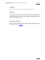
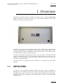
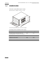
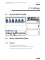
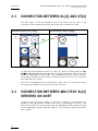
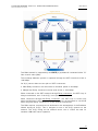
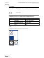
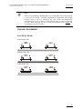
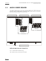
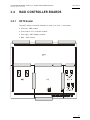
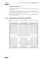
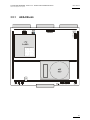
Technical Reference Hardware
Version 10.01 - May 2009
Production Proxy Server
XL Series DISK RECORDER - Version 10.01 - Hardware Technical Reference Manual
Issue 10.01.A
EVS Broadcast Equipment SA – May 2009
Copyright
EVS Broadcast Equipment – Copyright © 2009. All rights reserved.
Disclaimer
The information in this manual is furnished for informational use only and subject
to change without notice. While every effort has been made to ensure that the
information contained in this user manual is accurate, up-to-date and reliable,
EVS Broadcast Equipment cannot be held responsible for inaccuracies or errors
that may appear in this publication.
Improvement Requests
Your comments will help us improve the quality of the user documentation. Do not
hesitate to send improvement requests, or report any error or inaccuracy on this
user manual by e-mail to [email protected] .
I
Issue 10.01.A
XL Series DISK RECORDER - Version 10.01 - Hardware Technical Reference Manual
EVS Broadcast Equipment SA – May 2009
Table of Contents
TABLE OF CONTENTS .................................................................................................... II
1.
OVERVIEW............................................................................................................... 1
1.1 UNPACKING................................................................................................................................1
1.2 DIMENSIONS ..............................................................................................................................2
1.3 INSTALLALTION..........................................................................................................................3
1.4 SAFETY, COMPLIANCE AND OPERATING CONDITIONS........................................................4
1.4.1 Safety......................................................................................................................................4
1.4.2 EMC Standards.......................................................................................................................4
1.4.3 EMC Warning..........................................................................................................................5
1.4.4 CE Marking .............................................................................................................................6
1.4.5 Power Supply..........................................................................................................................6
Cold Swap..................................................................................................................................................................6
Hot Swap....................................................................................................................................................................7
Secondary Power Supply ...........................................................................................................................................8
Grounding ..................................................................................................................................................................8
1.5 VENTILATION & RACK MOUNTING ...........................................................................................8
1.6 XL[2] SERVER MAIN SPECIFICATIONS ....................................................................................9
1.6.1 Video.......................................................................................................................................9
1.6.2 Audio.......................................................................................................................................9
1.6.3 Video Codecs & Bitrates .........................................................................................................9
1.6.4 Recording Capacity for XL[2] Servers ...................................................................................10
1.6.5 Supported SMPTE Standards...............................................................................................10
1.6.6 Maximum Bitrate values........................................................................................................10
1.6.7 Raid level: 3 ..........................................................................................................................10
1.6.8 Interpolation ..........................................................................................................................11
2-line Interpolator .....................................................................................................................................................11
4-line Interpolator .....................................................................................................................................................12
2.
CABLING................................................................................................................ 13
2.1 XL[2] 6U BACK PLANE..............................................................................................................13
2.2 AUDIO CONFIGURATIONS ......................................................................................................13
2.2.1 CODA A2 ..............................................................................................................................13
2.3 CONNECTION BETWEEN XL[2] AND XT[2] .............................................................................14
2.4 CONNECTION BETWEEN MULTIPLE XL[2] SERVERS ON XNET..........................................14
2.4.1 Connection Diagram without EVS XHub SDTI HUB .............................................................16
2.4.2 Connection Diagram With EVS XHub SDTI HUB..................................................................17
2.4.3 Required conditions to set up and run XNet..........................................................................17
2.4.4 Starting XNet.........................................................................................................................19
2.4.5 XNet Performances & Troubleshooting.................................................................................19
2.5 GIGABIT CONNECTION............................................................................................................20
3.
HARDWARE DESCRIPTION ................................................................................. 21
3.1 SLOT CONFIGURATION...........................................................................................................21
3.2 VIDEO AND REFERENCE BOARDS ........................................................................................21
3.2.1 COHX Board .........................................................................................................................21
Jumpers on the COHX base module .......................................................................................................................22
II
XL Series DISK RECORDER - Version 10.01 - Hardware Technical Reference Manual
Issue 10.01.A
EVS Broadcast Equipment SA – May 2009
Leds on the COHX base module with gunlock.........................................................................................................23
Leds on the COD A and COD B modules (from left to right)....................................................................................23
Connectors on the COD A and COD B modules .....................................................................................................24
Channel Assignment ................................................................................................................................................25
3.3
AUDIO CODEC BOARD ............................................................................................................26
LED information and connector................................................................................................................................26
3.4 RAID CONTROLLER BOARDS .................................................................................................27
3.4.1 HCTX board ..........................................................................................................................27
Jumpers ...................................................................................................................................................................28
LEDs ........................................................................................................................................................................28
Connectors...............................................................................................................................................................29
Gigabit Connectors ..................................................................................................................................................30
3.4.2
RTCL Board on Disk Array (with HCTX) ...............................................................................30
LEDs ........................................................................................................................................................................31
3.5 MTPC BOARD ...........................................................................................................................32
3.5.1 A2/A4 Board..........................................................................................................................33
LED information: ......................................................................................................................................................34
Board configuration: .................................................................................................................................................34
III
XL Series DISK RECORDER - Version 10.01 - Hardware Technical Reference Manual
Issue 10.01.A
EVS Broadcast Equipment SA – May 2009
1. Overview
Welcome in the EVS range of products and thank you for using an EVS XL[2]
server. We will do our best to satisfy your video production needs and we look
forward to continuing working with you.
The EVS XL[2] servers ar e full digital in PAL (625i), NTSC (525i). Developed to
work as a complement to t he XT[2] production server, which allows users to work
in high resolution media in either SD or HD, the XL[2] server is the ideal solution
for large studio and major events production.
The XL[2] server allows ingesting the media in low resolution, in parallel with the
ingest on the XT[2] server. The users can then browse or review the lowresolution ingested media through the gigabit Ethernet connection to keep the
production running smoothly.
The XL[2] server is controlled by EVS’ IPDirector or through EVS open AVSP
protocol.
1.1
UNPACKING
On receipt of the equipment examine packi ng for obvious signs of damage. If
damaged, do not unpack and inform the carrier immediately. Check thanks to the
included packing list if all the items are present and if they show any mechanical
damage. If yes, report damage or the missing parts to EVS or their appropriate
representative.
1
Issue 10.01.A
XL Series DISK RECORDER - Version 10.01 - Hardware Technical Reference Manual
EVS Broadcast Equipment SA – May 2009
1.2
DIMENSIONS
Video disk recorder Main frame 19 inches
Rack mount 6U – Weight: 32.5 Kg/ 71.5 Lbs.
The following table specifies the various lengths:
Cold swap (without redundant power supply)
2
Description
Length (mm)
Length (inch.)
Rackable length (from behind the rack
mounting stripes to the back of the server)
603
23,7
Length without the front panel
627
24,7
Length with the handles
660
26,0
Length with the front panel
670
26,4
XL Series DISK RECORDER - Version 10.01 - Hardware Technical Reference Manual
Issue 10.01.A
EVS Broadcast Equipment SA – May 2009
Hot swap (with redundant power supply)
Description
Length (mm)
Length (inch.)
Rackable length (from behind the rack
mounting stripes to the back of the server)
640
25,2
Length without the front panel
662
26,1
Length with the handles
695
27,4
Length with the front panel
705
27,7
Hot swap power supplies sticks out by 25mm / 1’’ (H: 187mm / 7.2’ by W: 170mm /
6.65’)
Rack mounting stripes: L: 270 mm / 10.6” by W 21 mm / 0.8”
Handles: H: 55mm / 2.2” by L: 160 mm / 6.3” by W: 21 mm / 0.8”
Keyboard - Weight: 0.4 Kg / 0.9 Lbs.
1.3
INSTALLALTION
Important
Verify the disk recorder unit has the correct voltage specifications for
your power source prior to applying power.
(selectable 110/230 VAC on the rear panel of the power supply, or
autoswitch, depending on the type of power supply unit installed)
Main power switch is located at the front side (lower right corner) of the
unit.
Before turning on the power, open the front door of Video disk recorder unit to
check if all boards fit into their guides. If a board is out of its guides, remove
carefully the board and replace it in the same slot.
3
Issue 10.01.A
XL Series DISK RECORDER - Version 10.01 - Hardware Technical Reference Manual
EVS Broadcast Equipment SA – May 2009
1.4
SAFETY, COMPLIANCE AND OPERATING
CONDITIONS
1.4.1
SAFETY
This equipment has been designed and tested to meet the requirements of the
following:
EN 60950
European
Safety of information technology equipment
including business equipment.
IEC 950
International
Safety of information technology equipment
including business equipment.
In addition, this equipment has been designed to meet the following:
UL 1950 - USA
1.4.2
4
USA
Safety of information technology equipment
including business equipment
EMC STANDARDS
EN 55022
European
Emission Standard
EN 61000-3-2
European
Electromagnetic Compatibility (EMC) Part 3 (Limits);
Section2 ; limits for harmonic current emissions
(equipment input current <16A per phase)
EN 61000-3-3
European
European Electromagnetic Compatibility (EMC) Part
3 (Limits), Section 3; limitation of voltage fluctuation
and flicker in low-voltage supply systems for
equipment with rated current of 16 A.
EN 61000-4-3
European
European Electromagnetic Compatibility (EMC) Part
4 (Limits), Section 3; Testing and measurement
techniques - Radiated, radio-Frequency,
electromagnetic field immunity test.
EN 61000-4-4
European
European Electromagnetic Compatibility (EMC) Part
4 (Limits), Section 4; Testing and measurement
techniques - Electrical fast transient/burst immunity
test.
EN 61000-4-5
European
European Electromagnetic Compatibility (EMC) Part
4 (Limits), Section 5; Testing and measurement
techniques - Surge immunity test.
XL Series DISK RECORDER - Version 10.01 - Hardware Technical Reference Manual
Issue 10.01.A
EVS Broadcast Equipment SA – May 2009
1.4.3
EN 55022
European
Emission Standard
EN 61000-4-6
European
European Electromagnetic Compatibility (EMC) Part
4 (Limits); Section 6 ; Testing and measurement
techniques - Immunity to conducted disturbances,
induced by radio-frequency fields.
EN 61000-4-7
European
European Electromagnetic Compatibility (EMC) Part
4 (Limits), Section 7; harmonics and interharmonics
measurements and instrumentation, for power supply
systems and equipment connected thereto.
EN 61000-4-11
European
European Electromagnetic Compatibility (EMC) Part
4 (Limits); Section 11 ; Voltage dips, short
interruptions and voltage variations immunity tests.
EN 50082-1
European
European Generic Immunity Standard – Part 1:
Domestic, commercial and light industry
environment.
FCC
USA
Conducted and radiated emission limits for a Class
A digital device, pursuant to the Code of Federal
Regulations (CFR) Title 47 –
Telecommunications, Part 15: Radio Frequency
devices, subpart B-Unintentional Radiators.
EMC WARNING
Changes or modifications not expressly approved by the manufacturer for
compliance could void the user's authority to operate the equipment. This
equipment has been tested and found to comply with the limits for a Class B
digital device, pursuant to Part 15 of the FCC Rules. These limits are designed to
provide reasonable protection against harmful interference in a residential
installation. This equipment generates uses and can radiate radio frequency
energy and, if not installed and used in accordance with the instructions, may
cause harmful interference to radio communications. However, there is no
guarantee that interference will not occur in a particular installation. If this
equipment does cause harmful interference to radio or television reception, which
can be determined by turning the equipment off and on, the user is encouraged to
try to correct the interference by one or more of the following measures:
• Reorient or relocate the receiving antenna
• Increase the separation between the equipment and receiver
• Connect the equipment into an outlet on a circuit different from that to which
the receiver is connected
• Consult the dealer or an experienced radio/TV technician for help
5
Issue 10.01.A
XL Series DISK RECORDER - Version 10.01 - Hardware Technical Reference Manual
EVS Broadcast Equipment SA – May 2009
1.4.4
CE MARKING
The CE marking is affixed to indicate compliance with the following directives:
• 89/336//EEC of 3 May 1989 on the approximation of the laws of the Members
States to electromagnetic compatibility.
• 73/23/EEC of 19 February 1973 on the harmonization of the laws of the
Members States relating to electrical equipment designed for use within certain
voltage limits.
• 1999/5/EC of 9 March 1999 on radio equipment and telecommunications
terminal equipment and the mutual recognition of their conformity.
1.4.5
POWER SUPPLY
C OLD S WAP
This equipment is fitted with a wide-ranging power supply. It is suitable for supply
voltages of 100 to 240 Vac -10%+6% at 50 or 60 Hz nominal.
Connection to supply: Pluggable equipment Type A (EN60950 §1.2.5):
Equipment which is intended for connection to the building power supply wiring
via a non-industrial plug and socket-outlet or a non-industrial appliance coupler or
both. Correct mains polarity must always be observed. Do not use reversible
power plugs with this equipment.
Class of equipment: Class 1 equipment (EN60950 § 1.2.5): electric shock
protection by basic insulation and protective earth.
Rated voltage: 110 to 240Vac (single phase)
Rated frequency: 50/60 Hz
Related Current: 10 A (100 to 120 Vac range) 5 A (220 to 240 Vac range)
Input connector: CEE22/IEC 320 3-pin male receptacle
6
XL Series DISK RECORDER - Version 10.01 - Hardware Technical Reference Manual
Issue 10.01.A
EVS Broadcast Equipment SA – May 2009
Environmental conditions
The equipment should be kept in the following environmental conditions:
Temperature: 0°C to +40°C (32°F to 104°F) ambient with free air flow
Relative humidity: 0% to 90% (non-condensing)
Cooling requirements: Forced air cooling air flow from front to back
Handling/movement: Designed for fixed use when in operation
Storage and transportation temperature: 0°C to +70°C (32°F to 158°F)
Storage and transportation relative humidity: 0% to 90% (non-condensing)
H OT S WAP
This equipment is fitted with a wide-ranging power supply. It is suitable for supply
voltages of 115 to 240 Vac +/-10% at 47 or 63 Hz nominal.
Connection to supply: Pluggable equipment Type A (EN60950 §1.2.5):
Equipment which is intended for connection to the building power supply wiring
via a non-industrial plug and socket-outlet or a non-industrial appliance coupler or
both. Correct mains polarity must always be observed. Do not use reversible
power plugs with this equipment.
Class of equipment: Class 1 equipment (EN60950 § 1.2.5): electric shock
protection by basic insulation and protective earth.
Rated voltage: 115 to 240Vac (single phase)
Rated frequency: 47/63 Hz
Related Current: 8 A (100 to 120 Vac range) 4 A (220 to 240 Vac range)
Input connector: CEE22/IEC 320 3-pin male receptacle
Environmental conditions
Temperature: 0°C to + 50°C (32°F to 104°F) ambient with free air flow
Relative humidity: 0% to 90% (non-condensing)
Cooling requirements: Forced air cooling air flow from front to back
Handling/movement: Designed for fixed use when in operation
Storage and transportation temperature: 0°C to +70°C (32°F to 158°F)
Storage and transportation relative humidity: 0% to 90% (non-condensing)
7
Issue 10.01.A
XL Series DISK RECORDER - Version 10.01 - Hardware Technical Reference Manual
EVS Broadcast Equipment SA – May 2009
S ECONDARY P OWER S UPPLY
Cold swap 2 n d Power Supply
A 2 n d power supply (cold swap) for the disk recorder unit is available optionally.
To connect this 2 n d power supply in case of failure of the main one, remove the
metal plate in the top right corner of the back panel, and swap the large electrical
connector located inside this compartment.
This additional power supply should not be connected to mains when not in use.
Hot swap 2 n d Power Supply
A 2 n d power supply (hot swap) for the disk recorder unit is available optionally.
This additional power supply should be connected to mains to allow automatic
power switching to the second power supply would the first one fail.
The remote panel, the touch screen and the external ADA rack are fitted with an
AUTOSWITCH power supply. A 2 n d power supply (hot swap) for the disk recorder
unit is available optionally.
This additional power supply should be connected to mains to allow automatic
power switching to the second power supply would the first one fail.
G ROUNDING
Ensure the disk recorder unit is properly grounded at all times to avoid electrical
shock hazard.
1.5
VENTILATION & RACK MOUNTING
Adequate ventilation is obviously required for optimum performance. As result of
this consideration, ensure no other equipment is located close to the mainframe.
Important
• Remember that fans are used to air cool the equipment and protect it
from overheating.
• Do not block fans intakes during operations.
Having regard to the weight of the XL[2] chassis, support guides are required for
this unit into the rack mount. The front ears of the XL[2] unit are not designed to
support its full weight. Applying full weight on these might result in bending the
metal plate.
8
XL Series DISK RECORDER - Version 10.01 - Hardware Technical Reference Manual
Issue 10.01.A
EVS Broadcast Equipment SA – May 2009
1.6
XL[2] SERVER MAIN SPECIFICATIONS
1.6.1
VIDEO
Video Formats
1.6.2
XL[2] Server
Standard Definition
525i 59.94fps (NTSC)
625i 60fps (PAL)
Digital Interface
10-bit 4:2:2 Serial (SMPTE259M).
Full frame synchronizer at input.
Number of
channels (6RU
rack)
Monitoring &
Down-converters
6 REC channels,
Reference
Analogue Black Burst
1 CVBS or SDI (software select) per channel, with OSD
AUDIO
• up to 8 embedded audio channels per video
• no AES or analogue audio connector on mainframe
Audio Processing
• uncompressed audio
• 20 or 24 bit processing and storage
• audio scrub
1.6.3
VIDEO CODECS & BITRATES
The EVS XL[2] server uses an intra-frame video encoding technique. The XL[2]
server supports natively the MJPEG (SD) video codec.
The target bitrate of the encoded video stream can be set by the user within the
accepted range: 1 to 6 Mbps for standard definition.
The default values are MJPEG 3 Mbps for standard definition.
9
Issue 10.01.A
XL Series DISK RECORDER - Version 10.01 - Hardware Technical Reference Manual
EVS Broadcast Equipment SA – May 2009
1.6.4
RECORDING CAPACITY FOR XL[2] SERVERS
The following tables show the record duration for 1 record channel (i.e. 1 video +
2 stereo audio tracks in SD) with arrays of 300GB disks. These tables are valid
with the “ Operational Disk Size” parameter set to 100%.
The typical drive arrangement is an Internal/External module (4 + 1) x 300 GB
drives (total 1200 GB usable).
Compression + Bitrate + Audio Nr.
MJPEG / 3 Mbps / 4 audios
MJPEG / 3 Mbps / 8 audios
MJPEG / 3 Mbps / 16 audios
Disk Size
5x300GB
365 h
227 h
129 h
NTSC Compression + Bitrate + Audio Nr.
MJPEG / 3 Mbps / 4 audios
MJPEG / 3 Mbps / 8 audios
MJPEG / 3 Mbps / 16 audios
Disks Size
5x300GB
367 h
228 h
130 h
PAL
1.6.5
SUPPORTED SMPTE STANDARDS
The following standards are supported:
1.6.6
SD SDI
SMPTE 259M (525i 625i)
LTC
SMPTE 12M
D-VITC
SMPTE 266M
Vertical Ancillary Data
SMPTE 334M
MAXIMUM BITRATE VALUES
The maximum bitrate is 6 Mbps.
This maximum value is valid for XL[2] servers running Multicam version 10.00.xx
or higher.
1.6.7
RAID LEVEL: 3
The Video Raid uses striping process across 5 disk drives. The video and audio
data is striped over the first 4 drives while the parity information is saved on the
10
XL Series DISK RECORDER - Version 10.01 - Hardware Technical Reference Manual
Issue 10.01.A
EVS Broadcast Equipment SA – May 2009
fifth drive. If one drive is damaged, the Video Raid can use the parity information
to recover the missing information, so that operation can continue seamlessly
without bandwidth loss.
For more information on online rebuild, refer to the section dedicated to this
subject in the XT Technical Reference Software manual.
1.6.8
INTERPOLATION
The playing back of smooth slow motion pictures carries specific issues: since
some fields must be repeated at regular interval to provide the video at the
playback speed required by the operator, parity violation appears regularly on the
output video signal. This issue is specific to interlaced formats (525i, 625i and
1080i) and does not concern progressive formats (720p).
If O and E represent respectively the odd and even fields of a standard video
signal (50/60 Hz), we have:
The original video signal:
O E O E O E O E O E O E O E O E
The output video signal at 50% speed:
O O E E O O E E O O E E O O E E
The output video signal at 33% speed:
O O O E E E O O O E E E O O O E
The output video signal at 25% speed :
O O O O E E E E O O O O E E E E
Fields with parity violation are shown in bold, underlined letters. As it appears
from the above table, whatever the playback speed (with the exception of the
normal 100% playback speed), a number of fields violate the normal parity of the
output signal. This parity violation induces a 1-line shift of the field, resulting in a
vertical jitter of the picture. The jitter frequency depends upon the chosen
playback speed.
To avoid this phenomenon and provide a stable output picture, EVS developed 2
types of line interpolator: 2-line and 4-line interpolators. The interpolation
process can be enabled or disabled by the operator on all EVS slow motion
systems.
2- LINE I NTERPOLATOR
The 2-line interpolator actually generates a new field, when the original field is in
parity violation. Each line of this new field is calculated by a weighted average of
the 2 neighbouring lines. This process solves the problem of parity violation and
vertical jitter, but the drawback is a reduction of the vertical resolution on the
interpolated fields, that appear unfocused. Another by-side effect is the
alternation of original fields (perfectly focused) and interpolated fields
(unfocused), resulting in a "pumping" video signal.
11
Issue 10.01.A
XL Series DISK RECORDER - Version 10.01 - Hardware Technical Reference Manual
EVS Broadcast Equipment SA – May 2009
4- LINE I NTERPOLATOR
The 4-line interpolator uses a more sophisticated calculation based on the 4
neighbouring lines. By using suitable coefficients for the weight of each line in the
resulting calculation, we apply this interpolation to all fields. The final result is a
permanently, slightly unfocused picture. The advantage is a stable output signal
with no jitter and no "pumping", but the vertical bandwidth is even more reduced.
The interpolator is of course always disabled at 100% playback speed, because
there is no parity violation.
Whatever the choice, the resulting picture is thus always a compromise between
stability and resolution . With EVS systems, the operator always has got the
choice between any of the 3 above described techniques: no interpolation, 2-line
interpolation or 4-line interpolation. Even if the operator chooses to use the
interpolation, this process will be automatically disabled when not necessary
(100% playback for 50/60 Hz signal.
Note
All professional VTRs use line interpolation in PlayVar mode to avoid
vertical jitters.
Default value is interpolator off for all configurations.
12
XL Series DISK RECORDER - Version 10.01 - Hardware Technical Reference Manual
Issue 10.01.A
EVS Broadcast Equipment SA – May 2009
2. Cabling
2.1
XL[2] 6U BACK PLANE
2.2
AUDIO CONFIGURATIONS
2.2.1
CODA A2
Internal Audio Module: Embedded Audio only
• 2 Embedded audio groups (8 mono channels) per video channel
• Audio Monitoring: 4 analogue balanced mono outputs (XLR)
13
Issue 10.01.A
XL Series DISK RECORDER - Version 10.01 - Hardware Technical Reference Manual
EVS Broadcast Equipment SA – May 2009
2.3
CONNECTION BETWEEN XL[2] AND XT[2]
The SDI inputs of the low-resolution server will come from the loop of the
recorders of the corresponding XT[2] server that will run either SD or HD.
High-Resolution Server (XT[2])
Low-Resolution Server (XL[2])
IN
IN
OUT
J1
J4
In case the high-resolution server is in HD, you need to ensure that the REC
HDÎ SD Low Latency parameter defined on the high-resolution XT[2] in the EVS
Advanced Parameters is set to ‘ON ’. This parameter takes into account the oneframe delay between the HD IN (J8) connector and the SD OUT (J3) connector
that feeds the XL[2] server.
The VITC and embedded audio information is kept. The LTC and genlock inputs
will need to be cabled in the XL[2] and the XT[2] servers.
2.4
CONNECTION BETWEEN MULTIPLE XL[2]
SERVERS ON XNET
In major events production where the media is ingested in low-resolution in
parallel to the high-resolution ingest, each XL[2] is connected to an XT[2]. The
XL[2] servers and XT[2] servers have their own independent XNet network, as well
as an independent gigabit Ethernet network. The following schema represents
such a setup:
14
XL Series DISK RECORDER - Version 10.01 - Hardware Technical Reference Manual
Issue 10.01.A
EVS Broadcast Equipment SA – May 2009
The XNet network is composed by several XL[2] systems all connected with a 75Ohm coaxial cable (BNC).
The exchange between systems is operated through the SDTI interface at 540 or
1485 Mbps.
On XL[2] servers there are two pairs of SDTI connectors:
• XNet Relay connectors can be used at a maximum speed of 540 Mbps.
• XNet[2] Non-Relay connectors can be used at 540 or 1485 Mbps.
When connected on the SDTI network through Relay connectors, the SDTI loop is
always established, even if the XL[2] is not powered on.
When connected through Non-Relay connectors, the SDTI loop is closed only
when the Multicam software is started. It is therefore recommended to use XHub
when using Non-Relay connectors to avoid network interruptions.
The XNet requires a network server dedicated to the management of the Database
shared among all XL[2]s. This is assigned to one of the XL[2] systems on the
network. The XL[2] acting as the network server can of course be used for
standard LSM/video server operation.
15
Issue 10.01.A
XL Series DISK RECORDER - Version 10.01 - Hardware Technical Reference Manual
EVS Broadcast Equipment SA – May 2009
2.4.1
16
CONNECTION DIAGRAM WITHOUT EVS XHUB SDTI HUB
XL Series DISK RECORDER - Version 10.01 - Hardware Technical Reference Manual
Issue 10.01.A
EVS Broadcast Equipment SA – May 2009
2.4.2
CONNECTION DIAGRAM WITH EVS XHUB SDTI HUB
2.4.3
REQUIRED CONDITIONS TO SET UP AND RUN XNET
1. All systems on the network must be XL [2] servers, XFile[2] or XF[2], XStore[2]
or XHub[2].
2. The SDTI advanced option code (for network client, master or server modes)
must be validated in the options list.
3. They should all be running c ompatible software version. A warning message is
displayed when trying to connect an XL[2] system with a software version that
is not compatible with the network server.
4. The following parameters must be similar on all systems :
a. SDTI Speed (usually 540Mbps or 1485Mbps, from Hardware Configuration
menu)
17
Issue 10.01.A
XL Series DISK RECORDER - Version 10.01 - Hardware Technical Reference Manual
EVS Broadcast Equipment SA – May 2009
b. Number of clips
5. Network Type must be set to “ Server” on 1 XL[2] (and only 1) on the network.
The others must be set to either “ M aster” (to share clips and view others’
clips) or “ Client” (to share clips only).
6. A different network number must be specified for each XL[2] system that you
want to connect to the network. If the same network number is assigned to 2
different systems, the second one will not be able to connect and a warning
message will be displayed.
7. All XL[2]s must be connected with a good quality BNC 75O-hm cable to form a
closed loop. Connect the SDTI OUT connector of the first XL to the SDTI IN
connector of the second one, etc. until the loop is closed by connecting the
SDTI OUT connector of the last XL to the SDTI IN connector of the first one.
The SDTI loop must be closed at all times during network operation. If for any
reason the loop is open, all network communication will be interrupted and all
systems will automatically switch to stand alone mode. When the loop is
closed again, network operation will resume auto matically. This problem can
be avoided or limited using EVS XHub SDTI hub.
8. The distance shown in the table below is the ma ximum cable length between
two active EVS servers, or 2 SDTI reclockers, on an XNet SDTI network, using
a single piece of cable between 2 servers or 2 reclockers. Intermediate
connectors, patch panels, etc., might degrade these figures. Depending on the
number of servers connected on the network, the location of the master
server, the presence or not of an XHub SDTI hub, the actual m aximum values
may be high er than indica ted. If longer di stances between servers are
required , SDTI to fibre converters can be used, allowing distances over
tho usands of meters if ne cessar y. EVS has va lidated the following SDI-fibre
con verters:
a. Stratos Lightwave M edia
(www.stratoslightwave.com)
Converter
TX/RX
VMC-T-H-2/VMC-R-H-2
b. Telecast TX/RX292 (www.telecast-fiber.com )
c. Netw ork E lectronics SDI -EO-1 3T (electrical t o optical) / SDI-OE-S (optical
to electrical) (www.network-electronics.com)
d. Network Electronics HD-EO-13T (electrical to optical / HD-OE (optical to
electrical)
e. BlueBell BB320T (TX) and B B320R (RX) ( www.bluebell.tv)
Cable type
@ 1485 Mbps
@ 540 Mbps
RG59
45m / 148ft
100m / 328ft
RG6
90m / 484ft
180m / 590ft
RG11
120m / 393ft
250m / 820ft
Super HiQ
150m / 492ft
350m / 1148ft
Fiber
80km(*)
200km(*)
(*) 80km/200km is the total length of the return path, i.e. the actual distances
between the 2 servers connected via the fiber link is half of this value, i.e. 40 km
@ 1485Mbps, 100 km @ 540Mbps.
18
XL Series DISK RECORDER - Version 10.01 - Hardware Technical Reference Manual
Issue 10.01.A
EVS Broadcast Equipment SA – May 2009
Note
When reclockers are used, the total delay induced by these reclockers
between 2 active servers on the network may not exceed 15 μs.
2.4.4
STARTING XNET
1. When all above conditions are fulfilled, turn on all “ M asters” and “ Clients”
XL[2]s, and make sure the Multicam application is started on all of them. A
message appears bec ause they are looking for the “ Server” XL[2].
2. Turn on the “ Server” XL[2] and start the Multicam application. The other
XL[2]s should see the “ Server” arriving on the n etwork and will connect
automatically. Connection takes a few seconds (usually between 2 and 5 sec)
for each XL[2].
2.4.5
XNET PERFORMANCES & TROUBLESHOOTING
1. With the default settings, 10 real-time transfers can be achieved on the
network with standard definition pictures in normal conditions, and 3 real-time
transfers with super motion pictures. Copy of a clip between 2 servers on the
network can be made up to 5 times faster than real time, depending on
network occupancy.
With high definition pictures, these numbers are reduced to 3-4 real-time
transfers and copy clip 2 times faster than real time.
These performances are also limited by the disk bandwidth available from the
XL[2] where the clips are stored. If the XL[2] “ owning” the clips is doing
multiple playbacks at the same time, freezes can occur on the remote XL[2]
using those clips. Priority levels have been implemented to maximize network
bandwidth efficiency: PLAY requests have a higher priority than
SEARCH/BROWSE requests, which in turn have a higher priority than COPY
requests. Note that “ Live” (E2E) mode on a remote record train has the same
priority level as a SEARCH/BROWSE request.
2. Note that when working at 1485Mbps or 540Mbps, only passive SDI routing
equipment may be used. The use of active SDI equipment should be avoided,
because they could cause additional line delays and prevent the proper
operation of XNet.
3. If the start-up of the network at a specific speed does not work properly and
all machines are apparently configured properly and the Multicam is actually
started on all of them, this can be due to the fact that the selected cables to
connect all XL[2]s together are not suitable or too long to operate at such a
speed. You can decrease the speed of the SDTI network on all machines and
try working in this mode. The number of simultaneous real-time transfers you
can achieve is of course reduced.
19
Issue 10.01.A
XL Series DISK RECORDER - Version 10.01 - Hardware Technical Reference Manual
EVS Broadcast Equipment SA – May 2009
4. While working at 1485 Mbps, if the connection cannot be established, please
make sure that all equipments are set to the same speed and connected to the
non-relay connectors. All equipments should be started if not connected to an
XHub.
5. It is recommended to use XHub if the network speed is set to 1485 Mbps.
6. Once the network has been established, if the system acting as the network
server is disconnected or shut down, another system will automatically be
assigned to act as a new network server. The switch is automatic and
seamless. The next machine to be automatically assigned as new network
server is the one with the highest serial number in the SDTI network.
2.5
GIGABIT CONNECTION
The Gigabit connection between the XL[2] servers is only used for browsing
purposes by IPDirector. It is not used to transfer video and audio material to
external systems since the diffusion and archiving are performed on the high
resolution material.
For more information on the GigE network setup, refer to the EVS Support team.
20
XL Series DISK RECORDER - Version 10.01 - Hardware Technical Reference Manual
Issue 10.01.A
EVS Broadcast Equipment SA – May 2009
3. Hardware Description
3.1
SLOT CONFIGURATION
The EVS Disk Recorder contains all the EVS developed boards.
6U Frame
Slot
#
9
8
7
6
5
4
3
2
1
XL[2]
Disk Array
HCTX
CODA (Audio Codec)
(empty)
COHX Proxy #3
COHX Proxy #2
(empty)
COHX Proxy #1 Genlock
MTPC
3.2
VIDEO AND REFERENCE BOARDS
3.2.1
COHX BOARD
The COHX board is divided in 3 parts: COHX base (centre front and back), COD A
module (front left), and COD B module (front right).
COD A and COD B modules are the actual CODEC modules, each of them being
able to be configured by software as an encoder (for a record channel).
There are 2 versions of the COHX base : one with genlock, one without genlock.
The genlock model can easily be identified by the presence of 3 quartz
synthesizer at the back of the board, on the right-hand side, and by the presence
of the GLK and PSU OK LEDs on either side of the DIN connector at the centre
front of the board. Note that a COHX board with genlock must be installed as
COHX #1 in first position (slot 2) in an XL[2] system. A COHX board with genlock
can never be installed in any other slot, and thus can not be used instead of
COHX #2 or #3. Doing so will result in conflicting electrical signals inside the
system.
21
Issue 10.01.A
XL Series DISK RECORDER - Version 10.01 - Hardware Technical Reference Manual
EVS Broadcast Equipment SA – May 2009
J UMPERS ON THE COHX BASE MODULE
ST1, ST2:
These 2 jumpers must be installed on the last COHX board of
the server (i.e. on COHX #1, 2 or 3 if there are respectively 1,
2 or 3 COHX board installed in the server)
ST3 (SPARE):
« parking » for jumpers for ST1 and ST2 when these are not
used
ST4 (only on
COHX with
genlock) :
It must be set to HiZ (or not installed).
ST5 :
It defines the position of the board inside the server.
Note that the Genlock Loop connector on the back panel of the
XL[2] server must always be terminated with a 75 Ohm load if it
is not used.
It must be set to « 1 » for a COHX with genlock, and to « 2 » or
« 3 » for a COHX board without genlock, depending on its
position in the server.
22
XL Series DISK RECORDER - Version 10.01 - Hardware Technical Reference Manual
Issue 10.01.A
EVS Broadcast Equipment SA – May 2009
L EDS ON THE COHX BASE MODULE WITH GUNLOCK
GLK
Off
when the genlock module is not initialized
Blinks green
when the genlock module is properly initialized, but not valid
genlock signal is detected
On, steady
green
when the module is initialized and a valid genlock signal is
detected
Red
(intermittent)
when there is a genlock problem
Red (steady)
when a resync is needed
PSU OK
On (green)
when all voltages are present and in the allowed range,
otherwise the led is off
L EDS ON THE COD A AND COD B MODULES ( FROM LEFT TO
RIGHT )
CPU
Blinks green
to indicate CPU activity
On, steady
green
when there is a problem with the processor of the COD module
PLAY
On (green)
when the COD module is set by the software in play mode
Off
when the COD module is set in record mode
PVID
on (green)
when a valid video signal has been detected on the J8
connector (SD/HD SDI input), whether the COD module is in
play or record mode
23
Issue 10.01.A
XL Series DISK RECORDER - Version 10.01 - Hardware Technical Reference Manual
EVS Broadcast Equipment SA – May 2009
TF (transfer)
Blinks green
while data transfers occur between the COD module and the
HCTX board
M1, M2,
not yet used
M3, M4
C ONNECTORS ON THE COD A AND COD B MODULES
Connector
J1
SD mode
SDI/CVBS (*) monitoring
output (SD)
Connector label on rear panel
Character Outs, CVBS/SDI
J4
SDI monitoring output (SD)
Character Outs, SD
SDI input
J8
(SD)
SD IN
(*) The switch between SDI and CVBS on J1 is done by a software setting in the EVS Configuration
menu.
The following schema shows the connector positions:
24
XL Series DISK RECORDER - Version 10.01 - Hardware Technical Reference Manual
Issue 10.01.A
EVS Broadcast Equipment SA – May 2009
Note
Only front backplanes labelled BKP7 are compatible with COHX boards
(7 slots for 6U frames). The BKP7 backplanes (compatible with COHX
boards) have 3 rows of soldering per slot, while the backplanes
compatible with IO-E, COHD or COHU boards have 2 rows of soldering
per slot. Note that the top slot of BKP7 backplanes must always be
connected to the HCTX board.
C HANNEL A SSIGNMENT
6-ch XL[2] Server
Upper Codec (#5)
Middle Codec (#4)
Lower Codec (#2)
25
Issue 10.01.A
XL Series DISK RECORDER - Version 10.01 - Hardware Technical Reference Manual
EVS Broadcast Equipment SA – May 2009
3.3
AUDIO CODEC BOARD
The AUDIO CODEC board is the audio interface between the COHX boards and
the HCTX board. VIDEO CODEC and AUDIO CODEC board are tied to the HCTX
board with one Bus connector on the front side.
ANALOG
AES/EBU
LED INFORMATION AND CONNECTOR
LD 1-3: Internal EVS information only
LD4: transfer activity to/from the HCTX board
26
XL Series DISK RECORDER - Version 10.01 - Hardware Technical Reference Manual
Issue 10.01.A
EVS Broadcast Equipment SA – May 2009
3.4
RAID CONTROLLER BOARDS
3.4.1
HCTX BOARD
The HCTX board is actually divided in 4 parts (3 in front, 1 in the back).
• Front left : GBE module
• Front centre : CTL controller module
• Front right : SDTI XNet[2] module
• Back : CPU module
27
Issue 10.01.A
XL Series DISK RECORDER - Version 10.01 - Hardware Technical Reference Manual
EVS Broadcast Equipment SA – May 2009
J UMPERS
ST1-1 on controller module (front centre): jumper must be installed on ST1-1 only
when the HCTX board is used with previous video codec boards (SD CODEC6,
COHD, C O H U) . T his jumper is automatically detected by the software application,
and an error messag e is generated if it is not properly set
ST1-2, ST1-3 and ST1-4 on controller module are not used. No jumper must be
installed on these
ST1 on CPU module (rear c orner, left): for EVS internal tests only (used to reset
the board). Never install that jumper, or the board will be in a permanent reset
state!
LED S
LEDs on the XNet[2] module (SDTI), from left to right:
FRAMER
on (green)
when the signal on the XNet or XNet[2] IN connector is a valid
EVS SDTI signal
NET
on (green)
when the XNet SDTI network is actually established (SDTI loop
closed, correct speed, etc)
GP
not used
LEDs on the CTL controller module (centre), from left to right:
LED 1
lights red when an error occurs while booting the HCTX board
LEDs 2 to 8 :
display the boot sequence of the HCTX board (cfr note below)
DSP led :
blinks green to show DSP activity
LEDs on the GBE Gigabit module (left), from left to right:
28
LEDs
CPU1/CPU2
indicate that the processor is
alternately every 250 milliseconds
Other LEDs
The six other LEDs are for EVS internal use
running.
The
LEDs
blink
XL Series DISK RECORDER - Version 10.01 - Hardware Technical Reference Manual
Issue 10.01.A
EVS Broadcast Equipment SA – May 2009
Note
When booting the HCTX board, LEDs 1 to 8 will light according to the
following sequence :
Hardware reset
Æ
all LEDs on (1 : red ; 2
to 7 : green)
Setup of CPU basic
registers
Æ
led 2 on (green)
Check of CPU/PC
DPRAM
Æ
if error: led 1 on (red) +
led 8 on (green)
Æ
if check is successful:
led 3 on (green)
Polling for PC
commands
Æ
led 4 on (green)
Switchin g to enhanced
mode
Æ
led 5 on (green)
Executing PC
commands until
execution requests end
led 6 on (green)
Jump to SDRAM and execute microcode
C ONNECTORS
On the XNet[2] module (SDTI):
J3:
IN connector for XNet (SDTI network 270/540Mbp s with relay)
J4:
OUT connector for XNet (SDTI network 270/540Mbps with relay)
J5:
O UT connector
w ith out relay)
J6:
IN c onnector for XNet[2] (SDTI networ k 270/540/1485Mbps without
relay)
for
XNet[2]
(SDTI
network 270/540/1485Mbp s
Note
J3 must be used with J4, and J5 must be used with J6.
Never use J3 with J5 or J4 with J6.
29
Issue 10.01.A
XL Series DISK RECORDER - Version 10.01 - Hardware Technical Reference Manual
EVS Broadcast Equipment SA – May 2009
G IGAB IT C ONNECTORS
The two Gigabit connectors of the card are connected to the two Gigabit ports of
the back plane.
The Giga bit connectors m ust be on a netw ork that supports Jumbo Frames of (at
least) 9014 bytes Ethernet frames. One of the tested switch belongs to the Cisco
3750 G family, for example the WS-C3750G-24T-S.
For more information, refer to the Software Technical Reference manual for
setting up the IP addresses.
3.4.2
RTCL BOARD ON DISK ARRAY (WITH HCTX)
Disk Arrays on systems with HCTX Boards have a controller on the disk array
board.
30
XL Series DISK RECORDER - Version 10.01 - Hardware Technical Reference Manual
Issue 10.01.A
EVS Broadcast Equipment SA – May 2009
LED S
0/A – 1/B – 2/C – 3/D – 4/E (between the 2nd and 3rd disk from left in front) :
These LEDs match the position of the disks on the board, i.e. :
0/A
RTCL
3/D
1/B
2/C
4/E
Disk LE Ds
off
the corresponding disk is not started (not spinning)
on, fast blinking
(green)
the corresponding disk is starting (spinning)
on, steady (green)
the corresponding disk is started and used in the RAID
array
on, slowly blinking
(green)
the corresponding disk is started but not used in the RAID
array
TF (just behind the 5 disks LEDs) :
on (green)
when data is transferred between the RAID array and the HCTX
board.
If the led is nearly permanently on, it means that data is
transferred almost all the time between the RAID array and the
HCTX board, thus being close to the max. bandwidth of the
system.
STS (between the 1st and 2nd disk from left in front) :
on (green)
when RCTL RAID controller is properly booted.
ERR (next to STS) :
lights red
when errors occur during the data transfer between the RAID
controller and the disks
31
Issue 10.01.A
XL Series DISK RECORDER - Version 10.01 - Hardware Technical Reference Manual
EVS Broadcast Equipment SA – May 2009
3.5
MTPC BOARD
The function of the PC board is mainly the control of the Video hardware via the
software and to interface the peripheral equipment (i.e. remote controller) with
th e Video hardware.
The f oll owing MTPC board is used:
• A2/A4 with COMMEL HS870 motherboard and a new time code management
module (with bootable USB)
In st and ard c on figur ation the PC hardware is composed by:
• One mounting PC board, with serial ports, LTC reader and generator, is
controlled by the motherboard.
• IDE Syste m Hard disk: the IDE disk drive is used for storing the EVS software
and the D OS operating system. Neither audio nor video data is saved on this
disk. The capacity of this drive may vary depending on market availability, but
th e system partition is always set to 1GB. The remaining capacity of thi s drive
is not used.
• 128MB SDRAM modified. The SDRAM used has been modified to suit the
system requirements. Please contact EVS support for RAMs upgrade. Do not
use standard PC RA M modules.
32
XL Series DISK RECORDER - Version 10.01 - Hardware Technical Reference Manual
Issue 10.01.A
EVS Broadcast Equipment SA – May 2009
3.5.1
A2/A4 BOARD
33
Issue 10.01.A
XL Series DISK RECORDER - Version 10.01 - Hardware Technical Reference Manual
EVS Broadcast Equipment SA – May 2009
LED INFORMATION
Internal EVS informat ion
B OARD CONFIGURATION
HPOL, VPOL and ENVS are used to configure the composite sync generator used
in LSM TV mode (no effect if LSM is only used with a VGA monitor).
The HPOL jumper can be used to invert or not the VGA HS signal (Horizontal
Sync) to generate the composite output signal (TV mode)
The VPOL jumper can be used to invert or not the VGA VS signal (Vertical Sync)
to generate the composite output signal (TV mode)
The ENVS jumper can be used to enable or not the presence of the VGA VS
signal (Vertical Sync) in the composite output signal (TV mode)
If the LSM TV mode is used, these jumpers must be set-up according to EVS
recommendations, which depend on LSM software version and CPU board
model/revision:
With MPTC board A2/A3 or A2/A4, set up the jumpers as follows:
• HPOL=On; VPOL=Off; ENVS=On
REMOTE RESET jumpers are available to designate the remote(s)
from which the RESET command can be sent.
This command resets the whole system: PC and video hardware.
In standard configuration only Remote one (on RS422 port 1) is
allowed to reset the system.
Important
This jumper should be removed if the device connected to the RS422
port is NOT an EVS controller. Maximum voltage on pin 5 of an RS422
port of the XL[2] server should not exceed 5 Volt when the
corresponding jumper is engaged. Applying a higher voltage on pin 5
when the corresponding jumper is engaged will result in permanent
electronic damage to the board.
34
XL Series DISK RECORDER - Version 10.01 - Hardware Technical Reference Manual
Issue 10.01.A
EVS Broadcast Equipment SA – May 2009
Notes:
35
Issue 10.01.A
XL Series DISK RECORDER - Version 10.01 - Hardware Technical Reference Manual
EVS Broadcast Equipment SA – May 2009
Regional Contacts
AMERICA (NORTH & LATIN)
EVS Americas
Tel: +1 973 575 7811
Fax: +1 973 575 7812
Tech. line: +1 973 575 7813
[email protected]
EVS Canada
Tel: +1 514 750 7544
Fax: +1 514 750 7518
Tech. line: +1 973 575 7813
[email protected]
EVS Australia
Tel: +61 02 9452 8600
Fax: +61 02 9975 1368
Mobile: +61 420 307 387
[email protected]
EVS China
Tel: +86 10 6808 0248
Fax: +86 10 6808 0246
Tech. line: +86 139 1028 9860
[email protected]
EVS Hong-Kong
Tel: +852 2914 2501
Fax: +852 2914 2505
Tech. line: +852 9401 2395
[email protected]
EVS India
Tel: +91 22 6697 2999
Fax: +91 22 2673 2092
Mobile: +91 98 9017 5958
[email protected]
ASIA & PACIFIC
EUROPE, MIDDLE EAST & AFRICA
36
EVS Belgium
Headquarters
Tel: +32 4 361 7000
Fax: +32 4 391 7099
Tech. line: +32 495 284 000
[email protected]
[email protected]
marketing evs.tv
EVS Brussels
Tel : +32 2 421.78.78
Fax : +32 2 421.78.79
[email protected]
EVS France
Tel: +33 1 46 99 9000
Fax: +33 1 46 99 9009
Tech. line: +33 1 46 99 9003
[email protected]
EVS Iberica
Tel: +34 91 490 3930
Fax: +34 91 490 3939
Tech. line: +34 91 490 3933
[email protected]
EVS Italy
Tel: +39 030 296 400
Fax: +39 030 294 3650
Tech. line: +39 334 631 1493
[email protected]
XL Series DISK RECORDER - Version 10.01 - Hardware Technical Reference Manual
Issue 10.01.A
EVS Broadcast Equipment SA – May 2009
EVS Middle East
Tel: +971 4 365 4222
Fax: +97 1 4 425 3501
Mobile: + 971 50 887 8758
[email protected]
EVS UK
Tel: +44 1372 387 250
Fax: +44 1372 387 269
Tech. line: +44 1372 387 266
[email protected]
37
EVS Broadcast Equipment
Liège Science Park
16, rue Bois St Jean
B-4102 Ougrée
Belgium
Corporate
Headquarters
North & Latin America
Headquarters
Asia & Pacific
Headquarters
Other regional offices
available on
+32 4 361 7000
+1 973 575 7811
+852 2914 2501
www.evs.tv/contact
To learn more about EVS go to www.evs.tv


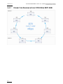
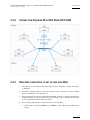
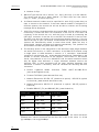


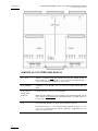


![2.8 conexión de varios servidores xt[2]](http://vs1.manualzilla.com/store/data/006305919_1-9948e093384d4040cdf0f68f445b7f43-150x150.png)