1
EQUIPMENT:
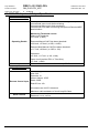
FIRECLASS DUO-CEL
WRITTEN BY: RKP
PUBLICATION:
OM_FC_DUO-CEL_APP
CHECKED BY: AP
ISSUE No. & DATE:
0
APPROVED BY: JBJ
01/03/12
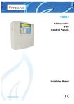
DUO-CEL
FIRE DETECTION/ALARM PANEL
Application Guide
PAGE 1 of 45
EQUIPMENT:
FIRECLASS DUO-CEL
WRITTEN BY: RKP
PUBLICATION:
OM_DUO-CEL_APP
CHECKED BY: AP
ISSUE No. & DATE:
0
01/03/12
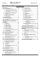
List of Contents
1. INTRODUCTION ...................................................... 4
2. GENERAL DESCRIPTION......................................... 4
2.1 CABINET SPECIFICATIONS ........................... 4
2.1.1 Panel Order Codes & Descriptions ........ 5
2.1.2 Replacement PCB Order Codes and
Descriptions ....................................... 6
2.1.3 Optional Language Display Overlays .... 6
2.2 FIRE DETECTION AND ALARM PANEL
DESCRIPTION.............................................. 7
2.2.1 DUO-CEL control board ......................... 7
2.2.2 Display overlay and insert ...................... 7
2.2.3 Power Supply ......................................... 8
2.2.4 Repeater Panel ...................................... 8
3. FUNCTIONAL SPECIFICATION ................................. 8
3.1 PANEL INPUT/OUTPUT LIST ......................... 8
3.2 FEATURES LIST ........................................... 9
4. DUO-CEL PANEL – CONTROL BOARD FEATURES 11
5. DUO-CEL REPEATER – CONTROL BOARD
FEATURES ........................................................ 12
6. POWER SUPPLY .................................................. 13
6.1 GENERAL.................................................. 13
6.1.1 Supply Input ......................................... 13
6.1.2 Supply Output ...................................... 13
6.1.3 Battery Charger .................................... 13
6.1.4 Battery Monitoring ................................ 13
6.1.5 Visual indications ................................. 14
6.1.6 Fault Conditions ................................... 14
6.2 MECHANICAL PROTECTION ........................ 14
6.2.1 DUO-CEL Power Supply Features and
Connections ..................................... 14
7. COMPATIBLE FIELD DEVICES ............................... 15
7.1 FIELD DEVICE PART NUMBERS .................. 15
8. OVERVIEW OF USER FUNCTIONS ......................... 18
8.1 USER INDICATIONS .................................... 18
8.2 USER CONTROLS ...................................... 19
8.3 SELECTION OF ZONES OR OUTPUTS FOR
DISABLEMENT, ENABLEMENT OR TEST ....... 20
8.4 DISABLED ZONES AND OUTPUTS ................ 20
8.5 DETECTOR ZONE TEST.............................. 20
8.6 ALARM SOUNDER ONE MAN TEST .............. 20
9. OVERVIEW OF ENGINEERS FUNCTIONS ................. 21
9.1 ENGINEER‟S CONFIGURATION PROCESS ..... 21
9.1.1 Zone Dependency selection ................ 21
9.1.2 Repeater configuration......................... 21
9.2 ZONE 1 NON-LATCH OPERATION ................ 22
9.3 RESISTOR EOL......................................... 22
9.4 TWIN W IRE ............................................... 22
9.5 ALERT MODE ............................................ 22
9.6 SELECTABLE ZONAL OR GENERAL ALARM
SOUNDER OPERATION ............................... 23
9.7 BUZZER DISABLE ...................................... 23
9.8 EARTH FAULT MONITORING........................ 23
10. PANEL REPEATERS ........................................... 23
10.1 REPEATER USER INDICATIONS ................... 24
10.2 REPEATER USER CONTROLS ..................... 25
11. CIRCUIT CONNECTION DETAILS.......................... 26
11.1 DUO-CEL PANEL MOTHERBOARD
TERMINATION DETAILS .............................. 26
11.2 DUO-CEL REPEATER MOTHERBOARD
TERMINATION DETAILS .............................. 27
11.3 AUXILIARY SUPPLY ................................... 27
11.4 FIRE SIGNAL OUTPUT ............................... 27
11.5 FIRE RELAY OUTPUT ................................ 27
11.6 FAULT RELAY OUTPUT .............................. 27
11.7 REMOTE CONTROL INPUT ......................... 28
11.7.1 Class Change .................................... 28
11.7.2 Alert ................................................... 28
11.7.3 Evacuate ............................................ 28
11.7.4 Silence Alarms ................................... 28
11.7.5 Reset ................................................. 28
11.8 OPEN COLLECTOR OUTPUTS..................... 28
11.8.1 Disabled Output ................................. 29
11.8.2 Evacuate Output ................................ 29
11.8.3 Buzzer Active Output ......................... 29
11.9 SOUNDER CIRCUITS.................................. 29
11.10 ELECTRICAL DESIGN OF DETECTION ZONES29
11.10.1 Standard Panel Default Zone
Configuration ................................... 29
11.10.2 Standard Panel Resistor Zone
Configuration ................................... 29
11.10.3 Twin-Wire Panel .............................. 29
11.10.4 Maximum Number of Detectors/MCPs
on a Zone ......................................... 30
11.11 PANEL TO REPEATER W IRING.................... 33
12. MECHANICAL & ELECTRICAL SPECIFICATION ..... 34
13. ENVIRONMENTAL SPECIFICATION....................... 35
14. DUO-CEL INPUT AND OUTPUT SPECIFICATION .. 36
15. APPENDIX ......................................................... 39
15.1 EN54 MANDATORY FUNCTIONS ................ 39
15.2 EN54 OPTIONAL FUNCTIONS W ITH
REQUIREMENTS ........................................ 39
15.3 ANCILLARY FUNCTIONS NOT REQUIRED BY
EN54....................................................... 39
15.4 SAFE STATE ............................................. 39
15.5 POWER SUPPLY LOAD CALCULATION......... 40
15.6 MINIMUM STANDBY BATTERY CAPACITY
CALCULATION ........................................... 40
15.6.1 Standby Battery Capacity Calculation
Worksheet ........................................ 42
15.7 A1466 INTERFACE RELAY ......................... 43
15.8 PANEL CONFIGURATION DESIGN CHART .... 44
16. GENERAL ASSEMBLY DRAWING ........................ 45
PAGE 2 of 45
EQUIPMENT:
FIRECLASS DUO-CEL
WRITTEN BY: RKP
PUBLICATION:
OM_DUO-CEL_APP
CHECKED BY: AP
ISSUE No. & DATE:
0
01/03/12
List of Figures
List of Tables
FIGURE 1 – PANEL/REPEATER ENCLOSURE EXTERNAL
VIEW ....................................................... 5
FIGURE 2 – DUO-CEL 8 ZONE PANEL – EXPLODED
VIEW ....................................................... 7
FIGURE 3 – PANEL CONTROL BOARD AND PCB COVER
............................................................ 11
FIGURE 4 – REPEATER CONTROL BOARD AND PCB
COVER .................................................. 12
FIGURE 5 – BAQ35T24 1.5A POWER SUPPLY LAYOUT
............................................................ 14
FIGURE 6 – DUO-CEL PANEL FIELD TERMINATIONS . 26
FIGURE 7 – DUO-CEL REPEATER FIELD TERMINATIONS
............................................................ 27
FIGURE 8 – FIRE SIGNAL OUTPUT CONNECTIONS ..... 27
FIGURE 9 – RELAY CONTACT CONNECTION DETAILS .. 27
FIGURE 10 – REMOTE CONTROL I/P CONNECTIONS .. 28
FIGURE 11 – ALARM CIRCUIT CONFIGURATION .......... 29
FIGURE 12 – TWIN-W IRE EOL DEVICE ..................... 30
FIGURE 13 – STANDARD ZONE W IRING DIAGRAM ..... 30
FIGURE 14 – RESISTOR EOL ZONE W IRING DIAGRAM
............................................................ 31
FIGURE 15 – TWIN-W IRE ZONE W IRING DIAGRAM .... 31
FIGURE 16 – ALARM CIRCUIT W IRING DIAGRAM ....... 32
FIGURE 17 – REMOTE INDICATORS W IRING DIAGRAM 32
FIGURE 18 – REPEATER W IRING DIAGRAM ............... 33
FIGURE 19 – A1466 INTERFACE RELAY SPECIFICATION
............................................................ 43
TABLE 1 – PANEL INPUT/OUPUT LIST .......................... 8
TABLE 2 – FLOAT CHARGE VOLTAGES FOR
POWERSONIC VRLA BATTERIES ............. 13
TABLE 3 – DUO-CEL PANEL DIL SWITCH
CONFIGURATION DESIGN/RECORD .......... 44
TABLE 4 – ZONE DEPENDENCY CONFIGURATION
DESIGN/RECORD ................................... 44
PAGE 3 of 45
EQUIPMENT:
FIRECLASS DUO-CEL
WRITTEN BY: RKP
PUBLICATION:
OM_DUO-CEL_APP
CHECKED BY: AP
ISSUE No. & DATE:
0
01/03/12
mounted to the back box. An ABS cover is fixed
1. Introduction
over the display/control board, leaving the field
This document contains technical information
necessary for application design using the
FIRECLASS DUO-CEL Conventional Fire Detection
control panel.
The following supporting documentation is also
available:
FIRECLASS DUO-CEL Sales Literature
FIRECLASS DUO-CEL User Manual
FIRECLASS DUO-CEL
Commissioning Manual.
FIRECLASS DUO-CEL Log Book.
Installation
and
Note: References are made throughout this
document to “Fire Signal Output” and “Fire Relay
Output”. These refer to particular outputs from the
panel and are provided for specific purposes:
Fire Relay Output: An output used to activate
ancillary fire protection equipment or systems.
For example, fire doors or plant shutdown.
Fire Signal Output: An output used to send a
common fire warning signal to a remote fire
monitoring station.
Detailed descriptions of both outputs are provided
within the following text.
The panel is currently available as a standard
conventional panel, with a twin-wire version soon to
be released. This document describes features
available for both types of panel.
2. General Description
The FIRECLASS DUO-CEL Panel range is fully
compliant with the mandatory requirements and
selected optional requirements of EN54 parts 2 and
4.
The FIRECLASS DUO-CEL equipment range
consists of the following:
terminals, configuration switches, links and user
controls easily accessible.
The front cover of the enclosure clips onto the back
box and is fixed by one screw on the top and two
screws on the bottom.
The PCB cover is fitted with a polyester overlay
providing user controls and indications. All display
text is printed on the overlay, with an insert for the
zone location text that slides into a pocket in the
overlay.
User controls are locked & unlocked via a plastic
key which is inserted through a keyhole in the cover
and cannot be removed when in the ON position.
All indications are implemented using LEDs, three
of which are not visible when the enclosure front is
fitted.
The power supply and standby batteries are
housed within the panel enclosure. The power
supply is fitted underneath the PCB with the mains
supply cable terminals accessible for easy
installation. The batteries are fitted in the back box
and retained by a plastic bar which is fixed to the
back box by a single screw.
Field cable Earth shields can be terminated to a
functional earth bar located in the rear of the panel
enclosure.
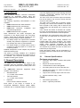
2.1
Cabinet Specifications
Enclosure construction:
Three-part high quality moulded ABS plastic
enclosure.
Keyhole for access control key.
14 knockouts for 20mm cable glands.
5 mounting holes in the rear of the back box.
Integral bezel design for surface mounting or
semi-flush mounting.
Standard Panels:
1, 2, 4 and 8 zone versions.
Logo recess on the top-right of the front cover.
Ingress Protection rating – IP30
Twin-Wire Panels:
1, 2, 4 and 8 zone versions.
Finish:
Repeater:
8 zone 24Vdc & 230Vac versions.
Each panel in the range is housed in an
Acrylonitrile Butadiene Styrene (ABS) Plastic
enclosure with a combined display & control board
Fine-texture (spark finish)
Colour – Light Grey RAL7035
PAGE 4 of 45
EQUIPMENT:
FIRECLASS DUO-CEL
WRITTEN BY: RKP
PUBLICATION:
OM_DUO-CEL_APP
CHECKED BY: AP
ISSUE No. & DATE:
0
01/03/12
GENERAL FIRE
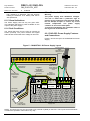
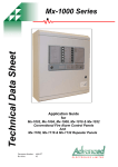
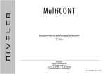
254 mm
SUPPLY ON
262 mm
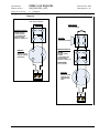
273 mm
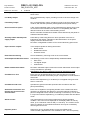
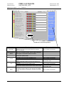
Figure 1 – Panel/Repeater Enclosure external view
EVACUATE
1
GENERAL FAULT
GENERAL TEST
GENERAL DISABLE
2
SILENCE
BUZZER
3
ALERT / EVAC ON
FIRE SIGNAL ON
FIRE SIGNAL FAULT
SILENCE /
RESOUND
ALARMS
4
5
SNDR FLT / DIS / TEST
SYSTEM FAULT
PSU FAULT
RESET
6
7
DISABLE
FUSED FAILED
8
EARTH FAULT
REPEATER FAULT
TEST
REMOTE I/P FAULT
CONTROLS ON
SELECT
365 mm
356 mm
348 mm
4 mm
77 mm
29 mm
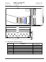
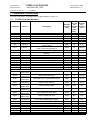
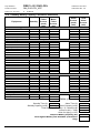
2.1.1 Panel Order Codes & Descriptions
CEL Part No.
508.031.701
508.031.707
508.031.702
508.031.708
508.031.703
508.031.709
508.031.704
508.031.710
508.031.705
508.031.706
Description
1 Zone Panel – Standard
1 Zone Panel – Twin-Wire
2 Zone Panel – Standard
2 Zone Panel – Twin-Wire
4 Zone Panel – Standard
4 Zone Panel – Twin-Wire
8 Zone Panel – Standard
8 Zone Panel – Twin-Wire
8 Zone Repeater c/w Mains AC Power Supply
8 Zone Repeater – DC Powered From Panel
PAGE 5 of 45
Internal SLA Battery
(Not Supplied)
24V, 3.4Ah
24V, 3.4Ah
24V, 3.4Ah
24V, 3.4Ah
24V, 3.4Ah
24V, 3.4Ah
24V, 3.4Ah
24V, 3.4Ah
24V, 3.4Ah
N/A
EQUIPMENT:
FIRECLASS DUO-CEL
WRITTEN BY: RKP
PUBLICATION:
OM_DUO-CEL_APP
CHECKED BY: AP
ISSUE No. & DATE:
0
01/03/12
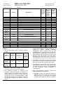
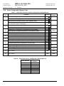
2.1.2 Replacement PCB Order Codes and Descriptions
CEL Part No
2605501
2605502
2605503
2605504
2605505
2605506
2605533
2605534
2605535
2605536
2501061
2000843
Description
Used in
1 Zone standard motherboard
2 Zone standard motherboard
4 Zone standard motherboard
8 Zone standard motherboard
Repeater c/w PSE motherboard
Repeater no PSE motherboard
1 Zone twin wire motherboard
2 Zone twin wire motherboard
4 Zone twin wire motherboard
8 Zone twin wire motherboard
Spare access controls key (1 off)
BAQ35T24 Power supply
508.031.701
508.031.702
508.031.703
508.031.704
508.031.705
508.031.706
508.031.707
508.031.708
508.031.709
508.031.710
All
All except repeater with no PSE
2.1.3 Optional Language Display Overlays
CEL Part No
Description
*** None Currently Available ***
PAGE 6 of 45
EQUIPMENT:
FIRECLASS DUO-CEL
WRITTEN BY: RKP
PUBLICATION:
OM_DUO-CEL_APP
CHECKED BY: AP
ISSUE No. & DATE:
0
2.2
01/03/12
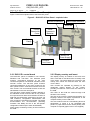
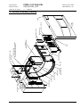
Fire Detection and Alarm Panel Description
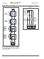
Figure 2 shows the exploded view of the DUO-CEL panel.
Figure 2 – DUO-CEL 8 Zone Panel – exploded view
Enclosure Backbox
Mains Cable Restraint
Earth Bar
3.4Ah
Powersonic
Batteries
Control
Board with
Cover
Battery
Clamp
BAQ35T24
Power Supply
Enclosure
Front Cover
2.2.1 DUO-CEL control board
2.2.2 Display overlay and insert
The DUO-CEL panel is available in two formats;
Standard and Twin-Wire. The standard panel
monitors conventional detectors on the zone
circuits and operates conventional sounders via the
sounder circuits. The twin-wire panel monitors
conventional detectors on the zone circuits but can
also operate Fulleon Twin-Wire sounders from the
zone circuits. The conventional sounder circuits are
still available on the twin-wire panel.
The Twin-Wire control board is slightly different to
the Standard control board but this is only evident
at component level. Both control boards consist of a
PCB with all components mounted on the front. All
LED indicators, configuration switches/links and
user controls are mounted on this board. The board
accommodates the microcontroller (including
Firmware and RAM) and all of the site-specific
configuration features (DIL switch & EEPROM).
Power supply monitoring circuitry is also located on
this PCB.
The display overlay is bonded to the PCB cover
and is used with a text label insert to identify each
of the zones. The insert slides into a pocket in the
overlay and cannot be removed when the front
cover is fitted.
User controls are operated by pressing on the
rectangular printed buttons on the overlay,
providing mechanical contact with the buttons on
the PCB.
The LEDs on the PCB are viewed through oval
windows in the overlay.
The text on the overlay is printed and therefore any
language variants will require replacement of the
complete overlay on the PCB cover.
The zone location insert is a card allowing text to be
hand-written or typed. It is not compatible with
printers. A paper insert can be used if printing via a
computer is required (paper insert is not supplied).
PAGE 7 of 45
EQUIPMENT:
FIRECLASS DUO-CEL
WRITTEN BY: RKP
PUBLICATION:
OM_DUO-CEL_APP
CHECKED BY: AP
ISSUE No. & DATE:
0
01/03/12
NOTE: The battery clamp is not designed to clamp
batteries other than the PS-1230.
2.2.3 Power Supply
The Power Supply is a self-contained switch-mode
unit and is mounted underneath the control board.
This unit provides 27.5VDC (nominal) at 1.5A to the
control board.
The output from the PSU is temperature
compensated, i.e. the battery charging voltage is
automatically adjusted to the safest optimum value
depending on the temperature of the batteries.
The PSU is connected to the control board by two
leads:
2.2.4 Repeater Panel
The repeater panel uses the same control board
and enclosure as the fire alarm panel. The
components for the redundant circuits [zones,
alarm circuits etc] are not present on the repeater
control board. The repeater and fire panel
mechanical arrangements are similar. The repeater
can be supplied with its own battery-backed
230VAC PSU, or without a PSU (powered directly
from the Fire Alarm panel‟s Auxiliary DC output).
Repeaters are only supported on the 4-zone & 8zone panels.
Up to 3 repeaters can be connected to the panel.
The panel controls the Repeaters through the
RS485 serial communications link.
The output lead has a 3-way socket, providing
0V, 28V and Mains Fault signals. (The
connector on the panel motherboard may
th
have a 4 pin for Functional Earth connection
from alternative power supplies).
The Thermistor lead connects to the
Thermistor socket on the control board, the
Thermistor being situated on the control
board. (The Thermistor is used to monitor the
battery temperature).
The control board provides connections for the
standby batteries via spade terminals.
The enclosure accommodates 2-off 12V 3.4Ah
Sealed Lead-Acid Powersonic PS-1230 batteries.
3. Functional Specification
3.1
Panel Input/Output List
See Table 1 below.
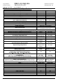
Table 1 – Panel Input/Ouput List
Input/Output
Detection zones
Multi-function Remote control
Input:
Class Change, Alert, Evacuate,
Silence alarms, Reset
1-Zone
1
2-Zone
2
4-Zone
4
8-Zone
8
1
1
1
1
Disablement Output
1
1
1
1
Evacuate Output
1
1
1
1
Buzzer Active Output
1
1
1
1
Standard Sounder circuits
2 @ 500mA
2 @ 500mA
4 @ 500mA
4 @ 500mA
Monitored Fire Signal Output
1 @ 250mA
1 @ 250mA
1 @ 250mA
1 @ 250mA
Auxiliary Fire Relay O/P
(Volt Free Change Over)
1
1
1
1
Auxiliary Fault Relay O/P
(Volt Free Change Over)
1
1
1
1
1 @ 250mA
1 @ 250mA
1 @ 250mA
1 @ 250mA
Auxiliary 28VDC Supply [fused]
Repeater facility
N/A
PAGE 8 of 45
Two terminals for serial
comms.
EQUIPMENT:
FIRECLASS DUO-CEL
WRITTEN BY: RKP
PUBLICATION:
OM_DUO-CEL_APP
CHECKED BY: AP
ISSUE No. & DATE:
0
3.2
01/03/12
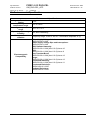
Features List
Enclosure
Injection moulded, 3-part, ABS plastic, flame retardant enclosure.
Surface or Semi-flush mounting.
14 x 20mm Gland knockouts at the top.
Temperature-compensated
battery charging
Battery charging voltage is automatically adjusted between 28.25Vdc and
26.72Vdc over an ambient temperature range of –5°C to +40°C.
Battery disconnect
Prevents permanent damage to the battery due to deep discharge by
automatically disconnecting it when the battery voltage falls below 21.6V.
Remote Control input providing
five controls:
1. Class Change
Operates all sounders for up to 5 seconds without giving any panel
indications.
2. Alert
Pulses all sounders and operates the fire buzzer.
3. Evacuate
Operates all sounders continuously and operates the fire buzzer.
4. Silence Alarms
Latches the Silence Alarms condition until a new alarm condition is
detected or until panel reset.
5. Reset
Returns the panel to the quiescent state after a fault or alarm
condition.
Configurable detection zones
DIL switch configuration provides the following capabilities:
Latching or non-latching Fire indication on zone 1.
Resistor or capacitor EOL monitoring – applies to all zones. (Not
functional on Twin-Wire panels)
Zone Short Circuit gives fault or fire alarm (for backwards
compatibility) – applies to all zones.
Factory configuration:
Latching zone 1 Fire indication
Capacitor EOL (not for twin-wire)
Zone Short circuit gives fault.
Selectable Zonal or General
Alarm Sounder operation
Selectable via DIL switches on the motherboard.
When set to Zonal, the sounders operate as follows:
Twin-wire panels ( 1 to 8 zone):
All 2-wire sounders operate zonally, normal sounder circuits operate
as general alarms
Standard panels, 1 to 4 zone panels:
Sounder circuits 1 to 4 operate individually for a fire condition on the
respective zone.
Standard panels, 8-zone panel:
Sounder circuits 1 to 4 operate as general alarms.
Alert Sounder operation
DIL switch selectable on the motherboard.
When the Alert Mode DIL switch is set to the ON position, sounders pulse
for automatic detector alarms and are continuous for Manual Call Point
alarms. NOT COMPATIBLE WITH RESISTOR EOL.
Zonally configurable co-incidence Programmable facility which allows any zone to be configured for co(dependency) for Automatic Fire
incidence (dependency) detection. Requires two occurrences of detector
Detectors
activation within 30 minutes before an alarm is raised. Manual call points
are not affected.
PAGE 9 of 45
EQUIPMENT:
FIRECLASS DUO-CEL
WRITTEN BY: RKP
PUBLICATION:
OM_DUO-CEL_APP
CHECKED BY: AP
ISSUE No. & DATE:
0
01/03/12
Fire Signal Output
Fully fault monitored output, providing 28VDC (nominal) at up to 250mA
when active.
Fire Relay Output
Non- monitored Relay output, providing one set of volt-free change-over
contacts.
Fault Relay Output
Non- monitored Relay output, providing one set of volt-free change-over
contacts, with fail-safe operation (fault signalled if total power failure)
Short Circuit Fire Option
A DIL switch selectable option on the motherboard to allow a short circuit
on the zones to be indicated as an alarm. For compatibility with older
detectors which do not have current limiting circuits.
NOTE: Automatic fire Detector activation will be detected by the panel as
a Manual Call Point alarm.
Auxiliary 24VDC 250mA power
supply output
Protected by a fast acting electronic fuse. Operation of the fuse is
indicated on the display. Operation of the Reset button on the panel
display resets the electronic fuse.
DIL switch configurable to switch off for 10 seconds during panel reset.
Open collector outputs
Three outputs capable of sinking 50mA each:
Buzzer Active.
Disablement Active.
Evacuate Active.
Earth Fault monitoring
Can be disabled by removing a link on the control board.
Zone/Output disablement feature
The following circuits can be independently disabled/enabled:
Each Zone
Fire Signal Output
All Sounders
Buzzer disablement feature
DIL switch selectable option to allow the buzzer and Buzzer Active output
to be prevented from operating.
Intended for use during commissioning and maintenance only.
One Man Zone Test
Each zone can be independently set to the One Man test condition.
Sounders will operate momentarily as per configuration of zonal alarms &
alert mode.
NOTE: Zone Dependency (co-incidence) is not applied during one-mantest on a test zone.
One Man Sounder Test
Operates the general sounders (and twin-wire sounders if twin-wire
panel) intermittently.
Automatic fire detector and
manual call point fire event
discrimination
Each zone is capable of recognising whether a fire condition has been
caused by an automatic fire detector or a manual call point (unless the
panel is configured to EOL resistor monitoring on the zones). This is used
in conjunction with the dependency (co-incidence) feature and Alert alarm
mode.
Alarm Counter
The panel keeps a record of the number times it enters the alarm
condition. This count can be displayed on the display LEDs as a binary
value, up to a maximum value of 999 (1111101001). The counter can be
reset via a button on the motherboard which can only be accessed by
removing the front cover.
Repeater panels
Support for up to 3 repeater panels via two-wire RS485 serial
communication. [Repeaters are not available for the 1 & 2 zone panels].
PAGE 10 of 45
EQUIPMENT:
FIRECLASS DUO-CEL
WRITTEN BY: RKP
PUBLICATION:
OM_DUO-CEL_APP
CHECKED BY: AP
ISSUE No. & DATE:
0
01/03/12
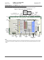
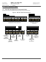
4. DUO-CEL Panel – Control Board Features
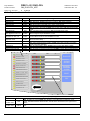
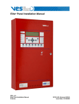
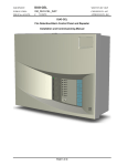
Figure 3 illustrates the control board for the 8 zone DUO-CEL panel with the PCB cover fitted.
Figure 3 – Panel control board and PCB cover
REMOTE
CONTROL
INPUT:
Class Change
Alert
Evacuate
Silence Alarms
Reset System
ZONE INPUTS.
FIRE
Also provides outputs for Twin-Wire
RELAY
Sounders on Twin-Wire panels.
FIRE
ROUTING
REMOTE
OUTPUTS:
Disabled
Evacuate
Buzzer Active
RS485
COMMS.
TERMINALS
FUSED
24VDC
OUTPUT
FAULT
RELAY
UNFUSED
24VDC
OUTPUT
ALARM CIRCUITS
PCB
ZONE 1
Z1 + Z1 –
ZONE 2
Z2+ Z2 –
ZONE 3
Z3+ Z3 –
ZONE 4
Z4+ Z4 –
ZONE 5
Z5+ Z5 –
ZONE 6
Z6+ Z6 –
ZONE 7
Z7+ Z7 –
ZONE 8
Z8+ Z8 –
FIRE SIGNAL
+
–
FIRE RELAY
N/O
P
N/C
FAULT RELAY
N/O
P
N/C
REMOTE
I/P
0V
REMOTE O/PS
DIS. EVAC. BUZ.
AUX 0.25A
24V
0V
REPEATER
A
B
24V
0V
A
B
AL1+ AL1 –
ALARM CIRCUITS
AL2+ AL2 – AL3+ AL3 – AL4+ AL4 –
ZONAL FIRE LEDs
PCB
COVER
EARTH FAULT
MONITORING
FC DUO-CEL 8 ZONE 1801306
ON
ZONAL FAULT LEDs
SUPPLY ON
GENERAL FIRE
OFF
EARTH FAULT
DISABLE LINK
INDOOR USE
ONLY
EVACUATE
1
GENERAL FAULT
2
GENERAL TEST
GENERAL LED
INDICATORS
GENERAL DISABLE
SILENCE
BUZZER
3
ALERT / EVAC ON
5
SILENCE /
RESOUND
ALARMS
6
RESET
4
FIRE SIGNAL ON
FIRE SIGNAL FAULT
SNDR FLT / DIS / TEST
SYSTEM FAULT
PSU FAULT
BATTERY
LEADS
REPEATER
FAULT LEDs
7
DISABLE
FUSED FAILED
8
EARTH FAULT
REPEATER FAULT
TEST
REMOTE I/P FAULT
THERMISTOR
LEAD
CONTROLS ON
CONFIGURATION
DIL SWITCHES
1: Z1 NON LATCH
2: RESISTOR EOL
3: ALERT MODE
4: DEPEND CONF
5: ZONAL ALARMS
6: S/C FIRE
7: AUX RESET
8: DISABLE BUZ
9: REP CONFIG
10: SNDR EXPAND
11: SPARE
12: SPARE
SELECT
FLT
FLT
FLT
POWER
SUPPLY
LEAD
BATTERY
FUSE
MOUNTING
TAB
REP 1
REP 2
REP 3
ALARM COUNT RESET SWITCH
ALARM
COUNTER
RESET
BUTTON
ZONE
LOCATION
INSERT
ACCESS KEY
ENTRY
USER
CONTROLS
MICROCONTROLLER
PROGRAMMING
SOCKET
INTERNAL
BUZZER
Note:
The Microcontroller programming socket is for use during manufacturing only and should not have any links
fitted across any of the pins. Improper use of the connector may result in permanent damage to the control
board.
PAGE 11 of 45
EQUIPMENT:
FIRECLASS DUO-CEL
WRITTEN BY: RKP
PUBLICATION:
OM_DUO-CEL_APP
CHECKED BY: AP
ISSUE No. & DATE:
0
01/03/12
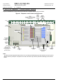
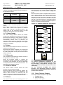
5. DUO-CEL Repeater – Control Board Features
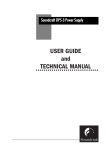
Figure 4 illustrates the control board for the DUO-CEL repeater with the PCB cover fitted.
Figure 4 – Repeater control board and PCB cover
24VDC
INPUT
For DC
powered
repeater
NOTE:
24V & 0V Terminals are only
available on the DC powered
repeater panel.
PCB
ZONE 1
Z1 + Z1 –
ZONE 2
Z2+ Z2 –
ZONE 3
Z3+ Z3 –
ZONE 4
Z4+ Z4 –
ZONE 5
Z5+ Z5 –
ZONE 6
Z6+ Z6 –
ZONE 7
Z7+ Z7 –
ZONE 8
Z8+ Z8 –
FIRE SIGNAL
+
–
FIRE RELAY
N/O
P
N/C
FAULT RELAY
N/O
P
N/C
REMOTE
I/P
0V
REMOTE O/PS
DIS. EVAC. BUZ.
AUX 0.25A
24V
0V
RS485
COMMS.
TERMINALS
REPEATER
A
B
24V
0V
A
B
AL1+ AL1 –
ALARM CIRCUITS
AL2+ AL2 – AL3+ AL3 – AL4+ AL4 –
ZONAL FIRE LEDs
PCB
COVER
FC DUO-CEL REPEATER 1801306
ZONAL FAULT LEDs
INDOOR USE
ONLY
SUPPLY ON
GENERAL FIRE
EVACUATE
1
GENERAL FAULT
GENERAL LED
INDICATORS
2
GENERAL TEST
GENERAL DISABLE
ALERT / EVAC ON
5
SILENCE /
RESOUND
ALARMS
6
RESET
4
FIRE SIGNAL ON
FIRE SIGNAL FAULT
SNDR FLT / DIS / TEST
REPEATER FAULT
CONFIGURATION
DIL SWITCHES
SILENCE
BUZZER
3
1: NUM REP A
2: NUM REP B
REPEATER PSU FAULT
7
TEST
PANEL PSU FAULT
8
EARTH FAULT
BATTERY
LEADS
COMM FAULT
REMOTE I/P FAULT
THERMISTOR
LEAD
CONTROLS ON
POWER
SUPPLY
LEAD
NOTE:
Power Supply
connections and
battery fuse are only
on the mains
powered repeater.
BATTERY
FUSE
ZONE
LOCATION
INSERT
MOUNTING
TAB
ACCESS KEY
ENTRY
USER
CONTROLS
MICROCONTROLLER
PROGRAMMING
SOCKET
INTERNAL
BUZZER
Note:
The Microcontroller programming socket is for use during manufacturing only and should not have any links
fitted across any of the pins. Improper use of the connector may result in permanent damage to the control
board.
PAGE 12 of 45
EQUIPMENT:
FIRECLASS DUO-CEL
WRITTEN BY: RKP
PUBLICATION:
OM_DUO-CEL_APP
CHECKED BY: AP
ISSUE No. & DATE:
0
01/03/12
6.1.3 Battery Charger
6. Power Supply
6.1
The power supply is capable of charging 2-off 12V
3.4Ah SLA Powersonic PS-1230 batteries.
The power supply unit monitors a Thermistor on the
panel control board and automatically adjusts the
output voltage to provide the optimum safe
charging voltage over an operating temperature
o
o
range of -5 C to +40 C.
The charging voltage can be adjusted via the
trimmer potentiometer VR1 on the PSU. However,
the charging voltage is factory set and adjustment
should not be necessary (a 15K resistor can be
o
used in place of the Thermistor to simulate 25 C).
General
The DUO-CEL uses a BENTEL BAQ35T24 switch
mode Power Supply which has the following
features:
Input voltage: 230 VAC 50/60Hz
Output voltage: 27.15VDC (nominal @ 25 C)
Stability over 1% with full load
Overload protection
Short-circuit protection
Insulation class 1
Tested and approved to EN 60950:1996 +
A4:1997
Dimensions: 130mm x 100mm x 38mm
o
NOTES:
1. The battery charging voltage is temperature
dependant and should be set as detailed in
Table 2. Charging at too high a voltage may
result in overheating, resulting in damage to
the batteries. Charging at too low a voltage
will result in insufficient charging of the
batteries.
2. The charging profile of the power supply unit
is optimised for Powersonic™ batteries and
charging of other manufacturers’ batteries is
not recommended. Consult your battery
supplier or battery manufacturer before use.
Table 2 – Float Charge Voltages for
Powersonic VRLA batteries
Weight: 389g
The battery monitoring circuit is part of the control
board. This provides:
Thermistor for temperature compensation
Battery/charger fault monitoring
Automatic
“battery
disconnect”
facility.
Disconnects the battery when the battery
terminal voltage falls below 21.6V, to prevent
deep discharge of the batteries if supplying the
panel for an abnormally long period of time.
Ambient
Temperature
6.1.1 Supply Input
The PSU is designed to run from mains voltage at
230Vac +10%, -15%, 50/60Hz. The input is
protected by a 3A 20mm glass fuse. The fuse is
inside the metal cage and is not user-serviceable.
6.1.2 Supply Output
The output from the PSU is 27.15Vdc ±1% at 25°C
with load up to 1.5A. The output is protected by a
6.3A 20mm glass fuse. The fuse is inside the metal
cage and is not user-serviceable.
The output current is shared between the panel
load and battery charging. The battery charging
current is therefore dependent on output current
and will fall to zero as the panel load approaches
1.5A.
The output is connected to the panel via a threewire flying lead, providing the DC power and a failsafe fault signal.
o
o
-10 C (14 F)
o
o
0 C (32 F)
o
o
10 C (50 F)
o
o
20 C (68 F)
o
o
25 C (77 F)
o
o
30 C (86 F)
o
o
40 C (104 F)
o
o
50 C (122 F)
Charger Set
voltage (V)
28.32 – 28.42
27.82 – 27.92
27.45 – 27.55
27.20 – 27.30
27.10 – 27.20
27.03 – 27.13
26.91 – 27.01
26.84 – 26.94
Float Charge
Voltage (V)
(2x12V
Batteries in
series)
27.84 – 28.44
27.60 – 28.20
27.36 – 27.96
27.12 – 27.72
27.00 – 27.60
26.88 – 27.48
26.64 – 27.24
26.40 – 27.00
6.1.4 Battery Monitoring
The health of the batteries, the battery connections
and fuse are checked by a battery monitor circuit on
the panel control board.
The batteries are monitored for disconnection. If
the battery voltage falls to 18V or below then a
PSU fault is raised and the charging voltage is
removed from the terminals.
The batteries are monitored for low voltage. If
the battery voltage drops below 21.6V when the
mains power is disconnected, then the batteries
are electronically disconnected to prevent deep
discharge. The batteries are reconnected only
after mains power is restored.
The batteries are monitored periodically for high
PAGE 13 of 45
EQUIPMENT:
FIRECLASS DUO-CEL
WRITTEN BY: RKP
PUBLICATION:
OM_DUO-CEL_APP
CHECKED BY: AP
ISSUE No. & DATE:
0
01/03/12
internal resistance. A PSU fault will be raised if
high resistance is detected. This test involves
loading the batteries so a battery load test is
also performed.
6.2
Mechanical Protection
Warning:
The power supply uses hazardous voltages.
The unit is fitted with a protective cage to
protect service engineers from electrical shock.
Do not attempt to open or access any of the
internal components. The power supply
contains no user serviceable parts.
To prevent overheating, the ventilation holes in
the cage must not be obscured.
6.1.5 Visual indications
The Power Supply Unit has only one green LED.
This indicates that there is power available on the
output of the power supply.
6.1.6 Fault Conditions
The yellow fault wire from the PSU is normally at
27Vdc (nominal). The panel monitors this signal
and indicates a PSU fault if the voltage is removed.
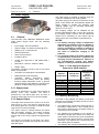
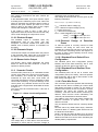
6.2.1 DUO-CEL Power Supply Features
and Connections
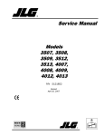
Figure 5 shows the layout of the BAQ35T24 Power
Supply.
Figure 5 – BAQ35T24 1.5A Power Supply Layout
Incoming Mains
Cable
Secured with a
cable tie to the
backbox
Earth Wire to
EARTH bar
Earth Wire to
Control Board
Mounting
Screw
Leave the
Earth wire 3cm
longer than the
Live & Neutral
wires
Negative
Temperature
Coefficient
Thermistor Input
Connector.
Power
Connection to
Control Board
TB2
THERMISTOR
L
Power
Connection to
Control Board
DC OUT
TO PANEL
B+
+
B-
+V
VR1
-
DC OUT
27V
GND
NTC
Thermistor
Connection to
Control Board
+V
ADJ
N
L
230VAC IN
1.5A Power
Supply Unit
NOTE: The black wire may be connected to (B-) instead of (GND) on the PSU. This is quite normal and does
not affect the operation of the PSU in any way.
PAGE 14 of 45
EQUIPMENT:
FIRECLASS DUO-CEL
WRITTEN BY: RKP
PUBLICATION:
OM_DUO-CEL_APP
CHECKED BY: AP
ISSUE No. & DATE:
0
01/03/12
7. Compatible Field Devices
The DUO-CEL panel is compatible with the devices listed in section 7.1.
7.1
Field Device Part Numbers
Manufacturer
Part no.
Description
Thorn/Tyco
Thorn/Tyco
Thorn/Tyco
Thorn/Tyco
Thorn/Tyco
Tyco
MF601
MR601
M600
MR601T
MD601
601CH
Tyco
601H-R
Tyco
601H-F
Tyco
601P
Tyco
601PH
Thorn/Tyco
Thorn/Tyco
Thorn/Tyco
Thorn/Tyco
Thorn/Tyco
Thorn
Tyco
Non Branded
CP200
MCP200
CP211
CP230
MCP230
CP260
MCP260
5B
Smoke Detector Ionisation
Smoke Detector Optical
Series 600 Universal Base
High Performance Smoke Detector Optical
Heat Detector Rate Of Rise
Conventional Enhanced CO Detector
Conventional Heat Detector
(Rate of Rise)
Conventional Heat Detector
Fixed Temperature {60 Deg C)
Conventional Optical Smoke Detector
Conventional High Performance Optical Smoke
Detector
Alert Manual call point (590R)
Alert Manual Call Point (590R)
Evacuate Manual Call Point (Current Limit)
Alert Manual call point (590R)
Alert Manual Call Point (590R)
Alert Manual Call Point (538R)
Alert Manual Call Point (538R)
5” Conventional Base
Apollo
Apollo
Apollo
Apollo
Apollo
Apollo
Apollo
Apollo
Apollo
Apollo
Apollo
Apollo
Apollo
Apollo
Apollo
Apollo
ORB-OP12001-APO
ORB-HT11001-APO
ORB-OH13001-APO
ORB-HT11006-APO
ORB-MB00001-APO
ORB-MB00002-APO
ORB-DB00003-APO
ORB-MB00012-APO
ORB-BA10008-APO
55000-217
55000-317
55000-122
55000-125
55000-132
55000-137
55000-200
Max.
Max.
Devices Devices
Standby
Per
Per
Current standard Twin-wire
(mA)
zone
zone
(10uF
EOL)
0.035
32
16 (30)
0.050
32
16 (24)
0.000
N/A
N/A
0.060
32
16 (20)
0.043
32
16 (27)
0.057
32
16 (21)
0.057
32
16 (21)
0.057
32
16 (21)
0.057
32
16 (21)
0.057
32
16 (21)
0.000
0.000
0.000
0.000
0.000
0.000
0.000
0.000
32
32
32
32
32
32
32
N/A
5
5
16
5
5
5
5
N/A
Orbis Optical Smoke Detector
0.093
32
12 (13)
Orbis A1R Heat Detector
0.093
32
12 (13)
Orbis Multi-sensor Smoke/Heat Detector
0.093
32
12 (13)
Orbis CS Heat Detector
0.093
32
12 (13)
Orbis TimeSaver Base
0.000
N/A
N/A
Orbis TimeSaver Base LX (simplified)
0.000
N/A
N/A
Orbis TimeSaver Diode Base
0.000
N/A
N/A
Orbis LX Base (low cost)
0.000
N/A
N/A
Series 65 to ORBIS Base Adaptor
0.000
N/A
N/A
Series 65 ionisation detector
Series 65 Optical detector
Series 65 heat detector A1R
Series 65 heat detector BR
Series 65 heat detector CR
Series 65 heat detector CS
Series 60 ionisation detector
0.035
0.050
0.035
0.035
0.035
0.035
0.035
32
32
32
32
32
32
32
16 (30)
16 (24)
16 (30)
16 (30)
16 (30)
16 (30)
NONE
PAGE 15 of 45
EQUIPMENT:
FIRECLASS DUO-CEL
WRITTEN BY: RKP
PUBLICATION:
OM_DUO-CEL_APP
CHECKED BY: AP
ISSUE No. & DATE:
0
01/03/12
Max.
Max.
Devices Devices
Standby
Per
Per
Current standard Twin-wire
(mA)
zone
zone
(10uF
EOL)
0.035
32
NONE
0.035
32
NONE
0.035
32
NONE
0.035
32
NONE
0.035
32
NONE
0.035
32
NONE
0.050
32
NONE
0.050
32
NONE
0.000
32
NONE
0.000
32
4
Manufacturer
Part no.
Description
Apollo
Apollo
Apollo
Apollo
Apollo
Apollo
Apollo
Apollo
Apollo
KAC
System
Sensor
System
Sensor
System
Sensor
System
Sensor
System
Sensor
55000-210
55000-100
55000-101
55000-102
55000-103
55000-104
55000-300
55000-380
45681-200
WR2072-470
Series 60 integrating ion detector
Series 60 Grade 1 heat detector
Series 60 Grade 2 heat detector
Series 60 Grade 3 heat detector
Series 60 Range 1 heat detector
Series 60 Range 2 heat detector
Series 60 optical detector
Series 60 optical/heat detector
Series 60 mounting base
Alert Manual call point (470R)
2351E
Optical Smoke Detector
0.160
20
8
2351TEM
Optical & Heat Detector
0.270
10
4
5351E
ROR Heat Detector
0.140
20
8
4351E
High Temperature Heat Detector
0.140
20
8
B401RSD
Base c/w 470R resistor & Diode
0.000
20
8
Fulleon
Fulleon
Fulleon
Fulleon
SQG3/SDR
SQG3/AV
Squashni
Symphoni
2-wire Squashni Sounder
2-wire Squashni Sounder Beacon
2-wire Squashni Sounder
2-wire Symphoni Sounder
0.050
0.050
0.050
0.050
N/A
N/A
N/A
N/A
12
8
4
9
Notes:
1. The recommended cable is FP200 or MICC
PYRO:
Capacita
Resistance Capacitance
nce per
CABLE
per Km
per Km
Km Core
1.5mm csa per Core Core to Core
to Screen
(Ω)
(uF)
(uF)
FP200
12.1
0.08
0.15
MICC
PYRO
12.1
0.19
0.21
Light Duty
MICC
PYRO
12.1
0.13
0.17
Heavy Duty
2. Maximum Cable length is 300m, or 3.63Ω per
core, 63nF core to core & core to screen.
3. The maximum number of detectors and
sounders per zone in section 7.1 assumes no
mixing of devices. The total number of detectors
and/or manual call points per zone must not
exceed 32. This is a recommendation of BS
EN54-2:1997 Annex D. The additional limitations
for twin-wire operation are listed in note (7)
below.
4. The Maximum number of devices per zone is
based
on
factory
default
monitoring
configuration [10uF capacitor EOL for the
standard panel or composite device for the twinwire panel]. For resistor EOL or Twin-Wire, the
total quiescent current drawn per zone by all
devices on the zone should not exceed 1.6mA.
Exceeding this current will result in a failure to
correctly detect an open circuit or head removal.
5. The number in brackets for the twin-wire zone is
the maximum number of devices allowed if NO
twin-wire sounders are connected to the zone.
6. The values are for guidance only and will vary
for individual detectors and cable types. Each
zone must be fully checked for correct operation
& fault monitoring during installation &
commissioning.
7. When using twin-wire sounders, observe the
following additional requirements:
PAGE 16 of 45
a. DO NOT exceed the maximum number of
sounders per zone as listed in the above
table in section 7.1. These figures are based
on extensive testing and allow for operation
EQUIPMENT:
FIRECLASS DUO-CEL
WRITTEN BY: RKP
PUBLICATION:
OM_DUO-CEL_APP
CHECKED BY: AP
ISSUE No. & DATE:
0
01/03/12
at low battery voltage and no mains power,
on long cable runs.
e. All detector bases must have a 1N4002
diode fitted across the line IN and line OUT
terminals (usually on the positive line but
sometimes on the negative line). Some
detector bases come with Schottky diodes
fitted. These are not compatible with the 2wire zone operation and must be replaced
with 1N4002 diodes. This applies even if no
sounders are connected. Use of a Schottky
diode will prevent the panel from detecting a
detector head removal.
b. When mixing different types of sounders on
the same zone, use the lowest quantity
shown in the table. For example, you can
have 12 SQG3/SDR on a zone as long as no
other sounders are connected on that zone.
If you want to mix SQG3/SDR with SQG3/AV
then the TOTAL number of sounders on the
zone should be limited to 8 (e.g. 7 x
SQG3/SDR and 1 x SQG3/AV).
c. DO NOT leave any detector bases empty. All
bases should have a detector fitted or be
linked through. Empty bases will introduce a
diode into the positive line and this will
adversely affect the operation of the
sounders.
d. Reducing the number of sounders WILL NOT
allow more detectors to be used, unless no
sounders are connected (see number in
brackets in the table).
8. If using detector bases without diodes fitted,
then removal of a detector head will result in an
open circuit of the cable. All devices fitted to the
zone cable beyond the detector head removed
will no longer be powered and will therefore not
operate. Only use detector bases without diodes
if the zone has no 2-wire sounders and no
Manual Call Points, or is configured to Resistor
EOL.
PAGE 17 of 45
EQUIPMENT:
FIRECLASS DUO-CEL
WRITTEN BY: RKP
PUBLICATION:
OM_DUO-CEL_APP
CHECKED BY: AP
ISSUE No. & DATE:
0
01/03/12
8. Overview Of User Functions
This section gives an overview of the functions available to the end user.
8.1
User Indications
Indicator
Colour
Supply On
General Fire
General Fault
General Test
General Disablement
Green
Red
Yellow
Yellow
Yellow
Alert/Evac On
Red
Fire Signal On
Red
Fire Signal Flt / Dis / Tst
Yellow
Sounder Flt / Dis / Dis
Yellow
System Fault
Yellow
PSU Fault
Yellow
Fuse Failed
Yellow
Earth Fault
Repeater Fault
Remote Control Fault
Controls On
Yellow
Yellow
Yellow
Yellow
General Indicator Section
Operating Condition
OFF: No mains or battery power, ON: Panel has power (battery and/or mains)
OFF: Quiescent, FLASH: New Alarm Condition, ON: Alarm Accepted
OFF: No faults present, FLASH: One or more faults present
OFF: No circuits in Test, ON: One or more circuits in Test
OFF: No circuits Disabled, ON: One or more circuits Disabled
OFF: No Alert or Evacuate, FLASH: Remote Alert active. ON: Remote Evacuate
active or Panel Evacuate active
OFF: Fire Signal output not active, ON: Fire Signal output active
OFF: No fault on Fire Signal output, FLASH: Fault on Fire Signal output,
ON: Fire Signal output Disabled or in test
OFF: No Fault on Sounder circuits, FLASH: Fault on one or more Sounder
circuits, ON: Sounder circuits Disabled or in Test
OFF: System is working correctly, ON: System is not functional. (Microcontroller
failed or EEPROM data corrupted)
OFF power supply is healthy, FLASH: PSU fault and/or battery fault
OFF: Auxiliary 24Vdc output available, FLASH: Electronic Fuse on Auxiliary
24Vdc output activated
OFF: No cable faults to Earth, FLASH: One or more cable faults to Earth
OFF: No Repeater faults, FLASH: One or more Repeater faults
OFF: No faults on Remote Control input, FLASH: Fault on Remote Control input
OFF: User Controls disabled, ON: User Controls enabled, FLASH: Select mode
active
SUPPLY ON
GENERAL FIRE
1
EVACUATE
GENERAL FAULT
GENERAL TEST
GENERAL DISABLE
2
3
ALERT / EVAC ON
FIRE SIGNAL ON
FIRE SIGNAL FAULT
5
SILENCE /
RESOUND
ALARMS
6
RESET
4
SNDR FLT / DIS / TEST
SYSTEM FAULT
PSU FAULT
SILENCE
BUZZER
7
FUSED FAILED
8
DISABLE
EARTH FAULT
REPEATER FAULT
TEST
REMOTE I/P FAULT
CONTROLS ON
SELECT
Indicator
Colour
User Zone
Location Text
Red
User Zone
Location Text
Yellow
Zone Location Indications
Operating Condition
OFF: No Alarm on zone, FLASH: New Alarm on zone, ON: Alarm accepted on zone.
NOTE: With Detector/MCP discrimination, the left LED is for MCPs, the right LED for
Detectors.
OFF: No Fault on zone circuit, FLASH: Fault on zone circuit, ON: Zone circuit Disabled or in
Test
PAGE 18 of 45
EQUIPMENT:
FIRECLASS DUO-CEL
WRITTEN BY: RKP
PUBLICATION:
OM_DUO-CEL_APP
CHECKED BY: AP
ISSUE No. & DATE:
0
8.2
01/03/12
User Controls
SUPPLY ON
GENERAL FIRE
EVACUATE
1
GENERAL FAULT
2
GENERAL TEST
GENERAL DISABLE
SILENCE
BUZZER
3
ALERT / EVAC ON
5
SILENCE /
RESOUND
ALARMS
6
RESET
4
FIRE SIGNAL ON
FIRE SIGNAL FAULT
SNDR FLT / DIS / TEST
SYSTEM FAULT
PSU FAULT
7
DISABLE
FUSED FAILED
8
EARTH FAULT
REPEATER FAULT
TEST
REMOTE I/P FAULT
CONTROLS ON
SELECT
Access Controls Keyswitch
Switch
Evacuate
Silence Buzzer
Silence/Resound
Alarms
Reset
Disable
Test
Functionality
Operates all sounders continuously and pulses the
Alert/Evac On LED until the Silence/Resound Alarms
button is operated
Silences the internal buzzer on the Panel & Repeaters.
When any sounders are active, press to silence sounders.
Press again to resound the silenced sounders.
Press to clear any fault & alarm conditions and return the
panel to the quiescent state
Displays Alarm Counter
Illuminates only the currently disabled circuits
Toggles the selected circuit between Disabled & Enabled
states.
Press to illuminate all LEDs and sound the buzzer for 5
seconds.
Illuminates only the circuits currently in test
Toggles the selected circuit between Test & Normal states.
Select
First operation enables the circuit select mode; subsequent
operations move the flashing cursor through the available
circuits until the last circuit and then exits the circuit select
mode.
PAGE 19 of 45
Button Availability
When controls are unlocked.
When controls are locked or unlocked
When controls are unlocked
When controls are unlocked
When controls are locked
When controls are unlocked
When controls are unlocked and in
circuit select mode
When controls are locked
When controls are unlocked
When controls are unlocked and in
circuit select mode
When controls are unlocked
EQUIPMENT:
FIRECLASS DUO-CEL
WRITTEN BY: RKP
PUBLICATION:
OM_DUO-CEL_APP
CHECKED BY: AP
ISSUE No. & DATE:
0
01/03/12
8.3
Selection of Zones or Outputs for
Disablement, Enablement or Test
The panel provides a simple and straightforward
means of selecting the sounder outputs and/or
zones which need to be disabled, re-enabled or set
to the test mode. The Fire Signal Output can also
be disabled and enabled or placed into the test
mode.
The zone or output is selected using the Circuit
Select feature. This allows the user to move a
flashing cursor indication down through the yellow
fault LEDs associated with the available circuits
until the required zone or output is highlighted. The
yellow LED for the selected zone/output flashes in
“Cursor” mode, which is easily distinguishable from
all other indications.
For each circuit that the Cursor is on, the General
Test and General Disablement LEDs will indicate
the current status of the circuit; flashing Test
indicates the circuit is in Test mode, flashing
Disablement indicates the circuit is disabled. Both
LEDs OFF indicates the circuit is in normal
operation.
If the circuit is in normal operation, pressing the
Disable button once will disable the circuit,
causing the General Disablement LED to flash
and the circuit fault LED to illuminate steady
(with flashing cursor).
If the circuit is in normal operation, pressing the
Test button once will set the circuit to test mode,
causing the General Test LED to flash and the
circuit fault LED to illuminate steady (with
flashing cursor).
If the circuit is currently disabled, pressing the
Disable button once will restore the circuit to
normal, causing the General Disablement LED
to switch off and the circuit fault LED to switch
off (with flashing cursor).
If the circuit is currently in test, pressing the Test
button once will restore the circuit to normal,
causing the General Test LED to switch off and
the circuit fault LED to switch off (with flashing
cursor).
If the circuit is currently disabled, pressing the
Test button once will change the circuit status
from disabled to test mode, causing the General
Disablement LED to switch off and the General
Test LED to flash.
If the circuit is currently in test, pressing the
Disable button once will change the circuit status
from test mode to disabled, causing the General
Test LED to switch off and the General
Disablement LED to flash.
NOTE: Disablements are stored in EEPROM and
are not lost when the panel is powered down. Test
conditions are cleared when the panel is powered
down.
8.4
Disabled Zones and Outputs
Any or all of the zones can be disabled.
A disabled zone will have power supplied to it but
will not report fire or fault conditions. The zone
power is switched off briefly when the zone is
disabled, and also when the zone is re-enabled.
Detectors on a disabled zone are still able to enter
the alarm condition but will not raise a fire alarm on
the panel.
In the twin-wire mode, sounders on disabled zones
will still be activated during a fire alarm unless the
sounders have been disabled.
The fire panel will respond normally to fire device
operations and wiring faults on all enabled zones.
The following outputs can also be disabled and
enabled:
All Sounder circuits including twin-wire (as a
group operation).
The Fire Signal Output.
A disabled output will not report fault conditions and
will not be activated, although power for monitoring
will still be applied.
8.5
Detector Zone Test.
When selected to the Test mode, devices
connected to the zone can be operated for test
purposes without operating the Fire Signal output or
the Fire Relay.
The zone(s) to be set to the One Man Test
condition are selected using the Cursor Select
feature described in 8.3.
The features of the One Man Zone Test condition
are:
A fire condition on a zone in Test Mode will not
operate any of the fire outputs.
Sounders operate for 5 seconds and then
automatically silence. Sounders operate in
general or zonal mode in accordance with the
panel configuration.
After each test the panel and the device being
tested are automatically reset allowing the next
device to be tested without needing to return to
the panel to silence and reset.
If a fire condition occurs on any zone other
than a zone in test mode, the panel responds
fully to the fire condition as per its normal fire
response and configuration.
8.6
Alarm Sounder One man Test
The One Man Sounder Test operates all sounders
on an intermittent basis until the Test mode is
manually cleared. This allows an engineer to walk
the protected area and confirm the operation of all
the sounders. The sounder on/off cycle is 2
seconds on and 15 seconds off to allow operation
PAGE 20 of 45
EQUIPMENT:
FIRECLASS DUO-CEL
WRITTEN BY: RKP
PUBLICATION:
OM_DUO-CEL_APP
CHECKED BY: AP
ISSUE No. & DATE:
0
01/03/12
to be confirmed without being too intrusive for other
occupants.
A genuine fire alarm condition overrides the test
mode and operates the sounders normally.
9. Overview of Engineers
Functions
This section provides an overview of the functions
available to the engineer.
9.1
Engineer’s configuration process
On the DUO-CEL panel, most of the Engineer‟s
configuration facilities are controlled by DIL
switches located on the motherboard, accessed by
removing the front cover of the panel. Each
configuration feature has its own dedicated DIL
switch. The DIL switches are as follows:
1: Z1 NON LATCH
2: RESISTOR EOL
3: ALERT MODE
4: DEPEND CONF
5: ZONAL ALARMS
6: S/C FIRE
7: AUX. RESET
8: DISABLE BUZ
9: REP CONFIG
10: SNDR EXPAND (not used)
11: SPARE
12: SPARE
Most functions simply require the appropriate DIL
switch to be either ON or OFF.
The DEPEND CONF DIL switch initiates a
programming mode in which the engineer is able to
select the required zone and set or clear it‟s
dependency mode status. The dependency mode
status is stored in EEPROM and is not lost if the
panel is powered down.
The REP CONFIG DIL switch (not available on the 1
& 2 zone panels) initiates a programming mode in
which the engineer is able to set the number of
repeaters connected to the panel. This data is
stored in EEPROM and is not lost when the panel is
powered down.
On the DUO-CEL repeater, only two DIL switches
are available:
1: NUM REP A
2: NUM REP B
Their setting is shown below:
Repeater No.
NUM REP A
NUM REP B
0 (Disabled)
OFF
OFF
1
ON
OFF
2
OFF
ON
3
ON
ON
9.1.1 Zone Dependency selection
When the zone dependency configuration DIL
switch (Depend Conf) is switched to the ON
position, the panel sounds the internal buzzer and
illuminates the SYSTEM FAULT LED to indicate
that the programming mode has been initiated. The
current status of the zones is displayed on the zone
fault LEDs; LED OFF – No Dependency, LED ON –
zone configured for dependency.
Operation of the SELECT button will then switch
the Select cursor on, flashing at the zone 1 fault
LED.
Pressing the Select button again will move the
flashing cursor to the next zone. The cursor will be
switched off after the last zone (1, 2, 4 or 8,
depending on the panel) or if no buttons are
pressed for 30 seconds.
Note that in the Engineer’s programming mode,
any faults, tests or disablements are masked
and are not shown on the display. The panel will
not respond to faults or fires.
With the cursor flashing on the required zone,
pressing the Disable button toggles the state of the
Dependency mode for that zone.
Once all required zones have been configured and
the configuration DIL switch is returned to the OFF
position, the panel will return to normal operation.
Factory default:
All zones are configured for no dependency.
Dependency Details:
This mode of operation conforms to BS EN542:1997 Clause 7.12.1 Type A Dependency.
Operation of an automatic fire detector on a zone
configured to the dependency mode will not
immediately indicate the fire alarm condition on the
panel. A 30-minute counter will be started and the
zone will be held in reset for 5 seconds (no power).
After the zone power is reinstated, if any automatic
fire detector on the same zone operates within 30
minutes, the panel will raise the fire alarm condition.
If no detectors or MCPs are operated on the zone
before the 30-minute timer ends, the zone will
return to coincidence detection (i.e. a detector
alarm on the zone will start the 30-minute timer
again).
Operation of Evacuate MCPs at any time will
always raise a fire alarm immediately.
Operation of an automatic fire detector or MCP on
any zone not configured for dependency will always
raise a fire alarm immediately.
9.1.2 Repeater configuration
When the Repeater configuration DIL switch (REP
CONFIG) is switched to the ON position, the panel
sounds the internal buzzer and illuminates the
SYSTEM FAULT LED to indicate that the
programming mode has been initiated. The current
PAGE 21 of 45
EQUIPMENT:
FIRECLASS DUO-CEL
WRITTEN BY: RKP
PUBLICATION:
OM_DUO-CEL_APP
CHECKED BY: AP
ISSUE No. & DATE:
0
01/03/12
status of the repeater configuration is also
displayed on the Repeater Fault LEDs, which are
visible when the front cover is removed.
Operation of the Select button will increment the
number of repeaters, up to a maximum of 3, after
which the number is reset to zero.
Number
REP1 FLT REP2 FLT REP3 FLT
of
LED
LED
LED
Repeaters
0
OFF
OFF
OFF
1
ON
OFF
OFF
2
ON
ON
OFF
3
ON
ON
ON
Once the required quantity of repeaters has been
configured and the configuration DIL switch is
returned to the OFF position, the panel will return to
normal operation.
Factory default: No Repeaters
9.2
Zone 1 Non-latch operation
The Zone 1 non-latch DIL switch allows zone 1 to
be set to non-latching fire indication.
In this mode a fire condition on zone 1 operates the
sounders but not the Auxiliary Fire Relay. The
alarm indication automatically clears when the fire
condition is removed from zone 1, without the need
to manually reset the panel.
9.3
Resistor EOL
The Resistor EOL DIL switch configures all zones
to monitor an end-of-line resistor (6K8 to 3K9)
instead of the default 10uF capacitor. This feature
is not available on the twin-wire panel (i.e. the
switch has no effect).
In the default mode, the panel actively checks for
the presence of a 10uF capacitor at the end of the
zone wiring. Diodes are fitted to detector bases and
removal of a detector will result in a fault condition
being raised at the panel whilst still providing power
to all devices on the zone.
In Resistor EOL mode, the panel monitors the
current drawn by the EOL resistor and indicates a
fault if the current drops below the threshold.
Diodes cannot be fitted to detector bases otherwise
a detector removal could not be detected.
Therefore, a removal of a detector will create an
open circuit and remove power from all devices
beyond the removed detector.
NOTE:
Resistor EOL monitoring is provided for older
installations where it is difficult to change the
EOL resistor to a capacitor.
In addition, detector/MCP discrimination will not
work when the zone monitoring is configured
for Resistor EOL and therefore zone alarm
dependency (coincidence detection) and Alert
Mode will not work correctly.
9.4
Twin Wire
The Twin Wire panels support Fulleon twin-wire
sounders on the zone circuits along with compatible
detectors (see section 7.1).
Each zone can monitor detectors and operate
sounders on the same two wires. The sounders are
activated by pulsing the zone voltage between
11Vdc & 24Vdc (nominal).
The EOL device consists of a Zener diode and
resistor which draws about 4mA in quiescent. A
detector head removal (assuming diode bases are
used) will result in a small voltage drop, which the
panel can monitor & indicate a zone fault.
The zones are also capable of discriminating
between detector and manual call point alarms and
so zone dependency mode is compatible with twinwire panels.
NOTE:
Only TYCO CP211 Manual Call Points can be
used. This is because standard call points will
apply a resistive load and if multiple call points
are operated on a single zone then the load will
be too great to allow the twin-wire sounders to
operate. The CP211 contains current limiting
circuitry such that multiple call points will draw
as much current as a single call point (current
is shared between call points) and will not affect
sounder operation. The CP211 also prevents
excessive loading on the zone when the zone
sounders are operated
9.5
Alert Mode
The Alert Mode DIL switch configures all zones to
discriminate between detector alarms and MCP
alarms. Detector Alarms are treated as Alert, MCP
alarms are treated as Evacuate.
The Sounder circuits are pulsed (1.5 second on, 1.5
second off) during the Alert alarm and operate
continuously during the Evacuate alarm.
When used in conjunction with Zonal Sounder
operation, a detector alarm will only pulse the
relevant zonal sounder circuit with all other sounder
circuits silent. A MCP alarm will operate the
relevant zonal sounder circuit continuously and
pulse all other sounder circuits.
On the display, the left zonal fire LED operates for
MCP alarms, the right zonal fire LED operates for
detector alarms.
NOTE:
Call points should be TYCO CP211 for TwinWire panels. For the standard panels the TYCO
CP211 or a conventional type may be used, but
the MCP resistor needs to be 220R to 360R.
Standard call points with 470R to 680R will be
monitored as a detector alarm instead of a MCP
alarm.
This feature will not work correctly with
Resistor EOL monitoring.
PAGE 22 of 45
EQUIPMENT:
FIRECLASS DUO-CEL
WRITTEN BY: RKP
PUBLICATION:
OM_DUO-CEL_APP
CHECKED BY: AP
ISSUE No. & DATE:
0
01/03/12
9.6
Selectable Zonal or General
Alarm Sounder operation
9.8
The Zonal Alarms DIL switch allows the sounder
circuits to operate zonally in line with the zone in
alarm. The actual operation of the alarm circuits will
vary depending on the type of zone detection and
number of zones available on the panel.
Twin-wire panels (1 to 8 zone):
All twin-wire sounders operate zonally, sounder
circuits on the motherboard operate as general
alarms (i.e. all four alarm circuits on the
motherboard operate for any zone fire)
Standard panels, 1 to 4 zone panels:
Sounder circuits 1 to 4 operate individually for a
fire condition on the respective zone.
Standard panels, 8-zone panel:
Sounder circuits 1 to 4 operate as general
alarms (i.e. all four alarm circuits on the
motherboard operate for any zone fire). Zonal
sounder operation is not available.
9.7
Buzzer Disable
The DISABLE BUZ DIL switch allows the panel
buzzer and Buzzer Active output to be disabled so
tat they do not operate for alarms or faults. The
panel buzzer will still operate for button presses.
The panel does not give any indication that the
buzzer has been disabled. This feature is
provided for use during panel commissioning
and maintenance only. Ensure that the DIL
switch is returned to the OFF position after
commissioning/maintenance
tests
are
complete.
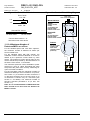
Earth Fault monitoring.
The DUO-CEL panel is designed to monitor for low
impedance faults to earth on the field cables. Earth
faults can lead to false alarms or failure to operate
the sounders or other outputs.
For installations where earth fault monitoring is
unsuitable, it can be disabled by removal of the
insulated jumper link (see Figure 3). The link can be
rotated and placed just on one pin rather than
across both pins. This should be done only after
all field cabling has been tested and confirmed
to be free from faults.
10. Panel Repeaters
The DUO-CEL repeaters duplicate the panel
indications and main user controls at a location
remote from the main panel. The repeater uses the
same enclosure & control board as the fire alarm
panel although most of the components are
depopulated from the control board. Up to 3
repeaters can be connected to a single panel using
an RS485 serial connection.
Each repeater can be powered either from the
Auxiliary 24Vdc output of the panel or an internal
power supply (optional).
Note:
The disable/enable/test facilities and the
configuration functions are not available at the
repeaters.
Repeaters cannot be used with the 1 & 2 zone
panels.
PAGE 23 of 45
EQUIPMENT:
FIRECLASS DUO-CEL
WRITTEN BY: RKP
PUBLICATION:
OM_DUO-CEL_APP
CHECKED BY: AP
ISSUE No. & DATE:
0
10.1
01/03/12
Repeater User Indications
Indicator
Colour
Supply On
General Fire
General Fault
General Test
General Disablement
Green
Red
Yellow
Yellow
Yellow
Alert/Evac On
Red
Fire Signal On
Red
Fire Signal Flt / Dis / Tst
Yellow
Sounder Flt / Dis / Tst
Yellow
Repeater Fault
Yellow
Repeater PSU Fault
Yellow
Panel PSU Fault
Yellow
Earth Fault
Communication Fault
Remote Control Fault
Controls On
Yellow
Yellow
Yellow
Green
General Indicator Section
Operating Condition
OFF: No mains or battery power, ON: Panel has power (battery and/or mains)
OFF: Quiescent, FLASH: New Alarm Condition, ON: Alarm Accepted
OFF: No faults present, FLASH: One or more faults present
OFF: No circuits in Test, ON: One or more circuits in Test
OFF: No circuits Disabled, ON: One or more circuits Disabled
OFF: No Alert or Evacuate, FLASH: Remote Alert active. ON: Remote Evacuate
active
OFF: Fire Signal output not active, ON: Fire Signal output active
OFF: No fault on Fire Signal output, FLASH: Fault on Fire Signal output,
ON: Fire Signal output Disabled or in Test
OFF: No Fault on Sounder circuits, FLASH: Fault on one or more Sounder
circuits, ON: Sounder circuits Disabled or in Test
OFF: Repeater is working correctly, ON: Repeater is in the SAFE state
(Microcontroller failed)
OFF: Power supply is healthy, FLASH: PSU fault and/or battery fault
OFF: Panel power supply is healthy, FLASH: Panel PSU has fault or Auxiliary
24Vdc output fuse activated
OFF: No cable faults to Earth, FLASH: One or more cable faults to Earth
OFF: Communication with Panel, FLASH: No communication with Panel
OFF: No faults on Remote Control input, FLASH: Fault on Remote Control input
OFF: User Controls disabled, ON: User Controls enabled
SUPPLY ON
GENERAL FIRE
1
EVACUATE
GENERAL FAULT
GENERAL TEST
GENERAL DISABLE
2
3
ALERT / EVAC ON
FIRE SIGNAL ON
FIRE SIGNAL FAULT
5
SILENCE /
RESOUND
ALARMS
6
RESET
4
SNDR FLT / DIS / TEST
REPEATER FAULT
REPEATER PSU FAULT
SILENCE
BUZZER
7
PANEL PSU FAULT
8
TEST
EARTH FAULT
COMM FAULT
REMOTE I/P FAULT
CONTROLS ON
Indicator
Colour
User Zone
Location Text
Red
User Zone
Location Text
Yellow
Zone Location Indications
Operating Condition
OFF: No Alarm on zone, FLASH: New Alarm on zone, ON: Alarm accepted on zone.
NOTE: With Detector/MCP discrimination, the left LED is for Detectors, the right LED for
MCPs.
OFF: No Fault on zone circuit, FLASH: Fault on zone circuit, ON: Zone circuit Disabled or in
Test
PAGE 24 of 45
EQUIPMENT:
FIRECLASS DUO-CEL
WRITTEN BY: RKP
PUBLICATION:
OM_DUO-CEL_APP
CHECKED BY: AP
ISSUE No. & DATE:
0
10.2
01/03/12
Repeater User Controls
SUPPLY ON
GENERAL FIRE
EVACUATE
1
GENERAL FAULT
2
GENERAL TEST
GENERAL DISABLE
SILENCE
BUZZER
3
ALERT / EVAC ON
5
SILENCE /
RESOUND
ALARMS
6
RESET
4
FIRE SIGNAL ON
FIRE SIGNAL FAULT
SNDR FLT / DIS / TEST
REPEATER FAULT
REPEATER PSU FAULT
7
TEST
PANEL PSU FAULT
8
EARTH FAULT
COMM FAULT
REMOTE I/P FAULT
CONTROLS ON
Access Controls Keyswitch
Switch
Functionality
Button Availability
Evacuate
Operates all sounders continuously and illuminates the
Alert/Evac On LED until the Silence/Resound Alarms
button is operated
When controls are unlocked.
Silence Buzzer
Silences the internal buzzer on the Panel & Repeaters.
When controls are Locked or
unlocked
Silence/Resound
Alarms
Reset
Test
When any sounders are active, press to silence sounders.
Press again to resound the silenced sounders.
Press to clear any fault & alarm conditions and return the
panel to the quiescent state
Press to illuminate all LEDs and sound the buzzer for 5
seconds
PAGE 25 of 45
When controls are unlocked
When controls are unlocked
When controls are locked
EQUIPMENT:
FIRECLASS DUO-CEL
WRITTEN BY: RKP
PUBLICATION:
OM_DUO-CEL_APP
CHECKED BY: AP
ISSUE No. & DATE:
0
01/03/12
11. Circuit Connection Details
11.1
DUO-CEL Panel Motherboard Termination Details
Figure 6 below shows the available field wiring terminals for the DUO-CEL Panel.
Figure 6 – DUO-CEL Panel field terminations
1 ZONE
2 ZONE
1 ZONE
2 ZONE
4 ZONE
4 ZONE
8 ZONE
8 ZONE
ZONE 1
ZONE 2
ZONE 3
ZONE 4
ZONE 5
ZONE 6
Z1 + Z1 – Z2+ Z2 – Z3+ Z3 – Z4+ Z4 – Z5+ Z5 – Z6+ Z6 –
ZONE 7
ZONE 8
Z7+ Z7 – Z8+ Z8 –
ALARM CIRCUITS
AL1+ AL1– AL2+ AL2– AL3+ AL3 – AL4+ AL4 –
SOUNDER OUTPUT
CIRCUITS
ZONE DETECTION CIRCUITS
1 ZONE
2 ZONE
1 ZONE
2 ZONE
1 ZONE
2 ZONE
4 ZONE
8 ZONE
4 ZONE
8 ZONE
REMOTE
I/P
0V
REMOTE O/PS
AUX 0.25A REPEATER
DIS. EVAC. BUZ. 24V
0V
A
B
24V
0V
A
B
FIRE SIGNAL
+
–
FIRE RELAY
N/O
P N/C
FAULT RELAY
N/O
P N/C
REMOTE
FUSED
FIRE SIGNAL
FAULT RELAY
UNFUSED
CONTROL INPUT:
24VDC
OUTPUT
CONTACTS:
24VDC
Class Change
OUTPUT FOR
Normally Closed
OUTPUT
Alert
REPEATERS
Pole
Evacuate
ETC.
Normally Open
Silence Alarms
FIRE RELAY
Reset System
CONTACTS:
REMOTE
RS485
NOT PRESENT
OUTPUTS:
Normally Closed
COMMS.
ON PANEL
Disabled
Pole
TERMINALS
Evacuate
Normally Open
Buzzer Active
PAGE 26 of 45
EQUIPMENT:
FIRECLASS DUO-CEL
WRITTEN BY: RKP
PUBLICATION:
OM_DUO-CEL_APP
CHECKED BY: AP
ISSUE No. & DATE:
0
01/03/12
11.2 DUO-CEL Repeater Motherboard
Termination Details
Figure 7 below shows the available field wiring
terminals for the DC powered DUO-CEL Repeater.
The mains AC powered repeater does not have the
two sets of terminals marked 24V & 0V.
Figure 7 – DUO-CEL Repeater field
terminations
AUX 0.25A REPEATER
24V 0V
A
B 24V
Figure 8 – Fire Signal Output Connections
Panel Terminals
+
10k
EOL
Quiescent: -5V DC
[open circuit voltage]
Active [fire]: 24V [nom]
0V
A
B
11.5
UNFUSED
24VDC
OUTPUT TO NEXT
REPEATER
(DC powered
repeaters only)
RS485
RS485
COMMS.
COMMS.
TO NEXT
FROM PANEL OR
REPEATER
REPEATER
UNFUSED
24VDC
INPUT
(DC powered
repeaters only)
Auxiliary Supply
An auxiliary supply is available to power the
repeaters and other external field equipment from
the panel. This voltage is nominally 27.15VDC but
varies with temperature and during mains-failed
conditions, depending on battery voltage. See
section 14 for details of maximum load.
The output is fused using an electronic device, and
fuse activation will be indicated as Fuse Failed on
the panel display. The fuse can be reset after
clearing the fault by operating the Reset button on
the display.
The auxiliary supply terminals are labelled Aux
0.25A 24V and 0V.
An additional UNFUSED 24V output is provided on
repeaters for connection to additional DC powered
repeaters.
Note: If equipment draws current from the
auxiliary supply during the mains-failed
condition this must be included in the battery
capacity calculations.
11.4
DIODE
1N4002
Output conditions:
-
11.3
Field Wiring
DIODE
1N4002
Fire Relay Output
The Fire Relay output is a single pole relay with
volt-free change over contacts. The relay is
normally de-energised and energises for any fire
alarm condition. The relay remains energised until
panel reset. This relay will not energise if zone 1 is
configured as non-latching and only zone 1 is in
alarm. See Figure 9 for details.
11.6
Fault Relay Output
The Fault Relay output is a single pole relay with
volt-free change over contacts. The relay is fail-safe
and is therefore normally energised, de-energising
for any faults. The marking on the control board
terminals is for the energised condition. See Figure
9 for details.
NOTE:
The volt-free relay contacts are rated at 30Vdc
with a maximum current of 1A. Do not exceed
the rated voltage and current.
Figure 9 – Relay contact connection details
Panel Circuit
Field Wiring
N/O
Fire Relay
P
Fire Relay shown in
de-energised condition.
N/C
N/O
Fire Signal Output
The Fire Signal output is fault-monitored in the nonenergised condition. It is designed to operate a
signalling relay at the routing equipment. The Relay
coil must be polarised and suppressed, because
the 10k end-of-line device is reverse-polarity
monitored for open & short circuit faults. See Figure
8 for details.
Fault Relay
P
Fault Relay shown in
energised condition.
PAGE 27 of 45
N/C
EQUIPMENT:
FIRECLASS DUO-CEL
WRITTEN BY: RKP
PUBLICATION:
OM_DUO-CEL_APP
CHECKED BY: AP
ISSUE No. & DATE:
0
11.7
01/03/12
Remote Control Input
A single 2-terminal input allows remote operation of
the following functions:
Control
Level
1
2
3
4
5
Function
Class Change
Alert
Evacuate
Remote Silence
Alarms
Remote Reset
Control
Resistor
4K7
2K2
1K
470R
220R
faults to be cleared, returning the panel to the
quiescent state. The Auxiliary 24VDC supply may
also be switched off for 10 seconds if configured to
do so.
When the Reset resistor is applied with the panel in
the fire alarm condition, any active sounder circuits
will be deactivated, all zone circuits will reset the
detectors, the fire relay will de-energise, the fault
relay will deactivate and all fire and fault indications
will clear. The Reset function is momentary and the
resistor needs to be removed and applied again in
order to re-operate the Reset function.
Figure 10 – Remote Control I/P connections
Control Level 1 is lowest priority, 5 is highest
priority.
The input is monitored for open and short circuit
faults. Each control level requires a different
resistor load as shown in the above table. A 10K
resistor acts as the end-of-line device for fault
monitoring. See Figure 10 for wiring details.
10K ¼ W EOL
4K7 ¼ W
CLASS
CHANGE
11.7.1 Class Change
The Class Change function allows all sounder
circuits to be operated for a maximum of 5 seconds.
When the Class Change control resistor is applied,
the sounders will operate continuously and then
automatically silence after 5 seconds. No
indications will be given on the panel. The resistor
needs to be removed and applied again if the signal
needs to be repeated.
2K2 ¼ W
1K ¼ W
470 ¼ W
11.7.2 Alert
220R ¼ W
The Alert function allows all sounder circuits to be
operated in pulsing mode.
When the Alert resistor is applied, the sounders will
pulse until the resistor is removed. The Alert/Evac
On LED will illuminate on the panel and the internal
buzzer will sound.
11.7.4 Silence Alarms
The Silence Alarms function allows all active
sounder circuits to be deactivated.
When the Silence Alarms resistor is applied, any
active sounder circuits will be deactivated. The
Silence Alarms function is momentary and the
resistor needs to be removed and applied again in
order to re-operate the Silence Alarms function.
11.7.5 Reset
The Reset function allows all standing alarms and
EVACUATE
SILENCE
ALARMS
RESET
REMOTE
I/P 0V
11.7.3 Evacuate
The Evacuate function allows all sounder circuits to
be operated in continuous mode.
When the Evacuate resistor is applied, the
sounders will operate continuously until the resistor
is removed. The Alert/Evac On LED will illuminate
on the panel and the internal buzzer will sound. The
Evacuate output will also operate.
ALERT
Note:
To prevent unauthorised operation of the
system, any manually operated function must
be operated by a key-switch. The key to the
switch should be held with the panel’s access
control key.
For the SILENCE ALARMS and RESET
functions, the Keyswitch should be springbiased so that it automatically returns to the off
position when released.
11.8
Open Collector Outputs
Three open collector outputs are provided:
1. Disabled (DIS.)
2. Evacuate (EVAC.)
3. Buzzer Active (BUZ.)
PAGE 28 of 45
EQUIPMENT:
FIRECLASS DUO-CEL
WRITTEN BY: RKP
PUBLICATION:
OM_DUO-CEL_APP
CHECKED BY: AP
ISSUE No. & DATE:
0
01/03/12
They are referred to as „open collector‟ because
each output is connected to the open collector pin
of a transistor.
In the deactivated state, each open collector output
is floating and is effectively open circuit. When the
output is activated, the transistor allows current to
flow from the open collector pin down to 0V. Each
output is able to sink 50mA when active. Higher
currents will damage the transistor driver.
If the output is used to drive a relay then a
suppression diode should be used across the relay
coil to avoid damaging the output driver circuit.
11.8.1 Disabled Output
The Disabled output is activated when any
disablements exist on the panel. The only
exceptions are Buzzer Disable and Earth Fault
Disable, both of which produce no indications on
the panel.
11.8.2 Evacuate Output
The Evacuate output is activated when the panel is
in the Evacuate state, either due to the button on
the display or due to the Remote Control input.
the end of each circuit exceeds the minimum
required by each sounding device.
The voltage at the end of the circuit is given by the
following calculation:
Valmin = Vopmin – (Ial x 2 x Lal x Rcable)
Valmin = Minimum Alarm Voltage (V)
Vopmin = Minimum Output Voltage (19.5V)
Ial = Alarm Current (A)
Lal = Alarm Circuit length (M)
Rcablel = Cable Resistance per metre ()
2
1.5mm – 0.015 per metre per core
2
2.5mm – 0.009 per metre per core
11.10 Electrical Design of Detection
Zones
To allow the panel to correctly monitor for fault
conditions, the wiring for each zone must be
installed as a continuous pair with no spurs or tees.
The end-of-line monitoring device will depend on
the type of panel. Correct polarity must be strictly
observed throughout.
11.8.3 Buzzer Active Output
11.10.1 Standard Panel Default Zone
Configuration
The Buzzer Active output duplicates the panel
buzzer for alarm and fault conditions. It does not
operate for button presses.
The standard panel zone configuration (factory
Default) uses active fault monitoring, with a 10uF
capacitor as the EOL device (see Figure 13).
11.9
11.10.2 Standard Panel Resistor Zone
Configuration
Sounder Circuits
The DUO-CEL panel has up to 4 standard sounder
circuits, each rated at 0.5 Amps (not including twinwire sounders). The circuits are reverse polarity
monitored for open and short circuit faults. All
connected field devices must be polarised to allow
correct fault monitoring. To prevent damage to the
control panel, any solenoid devices such as bells
must also have a suppression diode fitted as shown
in Figure 11.
The circuit must be terminated with a 10K end of
line resistor.
Figure 11 – Alarm circuit configuration
Alarm +
Suppression
diode
[1N4002S]
Polarising
diode
[1N4002S]
10K
EOL
Resistor
Bell
Electronic
sounder
Alarm -
The standard panel can be set to resistor zone
configuration (set by DIL switch). This uses passive
fault monitoring, with a 6K8 to 3K9 resistor as the
EOL device (see Figure 14).
11.10.3 Twin-Wire Panel
The Twin-Wire panel uses passive fault monitoring
but with an EOL device consisting of a zener diode
and resistor as shown in Figure 12. The device is
polarised and should not be connected in reverse
(otherwise the panel will indicate an alarm
condition). This EOL device allows monitoring for
detector head removal whilst maintaining line
continuity via diodes fitted to detector bases.
The addition of the zener and resistor enables the
twin-wire sounders to operate, even with one
detector removed.
Only use detector bases with line continuity diodes
fitted.
DO NOT leave any diode bases empty. Detectors
should be fitted or a blanking plate which links out
the diode should be fitted.
NOTE: The twin-wire EOL will draw up to 4mA from
the zone in quiescent and this should therefore be
added to the total zone current when calculating the
standby battery requirements.
The voltage drop on each alarm circuit should be
calculated to ensure that the minimum voltage at
PAGE 29 of 45
EQUIPMENT:
FIRECLASS DUO-CEL
WRITTEN BY: RKP
PUBLICATION:
OM_DUO-CEL_APP
CHECKED BY: AP
ISSUE No. & DATE:
0
01/03/12
Figure 12 – Twin-Wire EOL device
Figure 13 – Standard Zone Wiring Diagram
Zener Diode
17V 5W
10uF 35V
end-of-line Capacitor
+ve
Manual Call Point.
-ve
ALERT:
CP200, CP230,
CP260
or equivalent with
internal resistor
between 470R & 1K
Resistor
330R 1W
Sleeved EOL device
+ve Thick Lead
EVACUATE:
CP211
Or equivalent with
internal resistor
between 360R & 220R
-ve Thin Lead
Connect bare leads to + & terminals in last zone device
Detector.
11.10.4 Maximum Number of
Detectors/MCPs on a Zone
For the standard panel with 10uF EOL capacitor,
the maximum number of detectors & MCPs per
zone is limited to 32.
For the standard panel with EOL resistor, the
maximum number of devices allowed on a zone is
limited by the quiescent current drawn by each
device. The quiescent current will be listed on the
device data sheet provided by the Manufacturer of
the device. See section 7.1 for details.
The maximum quiescent current available to power
devices on a zone is 1.6mA. Exceeding this value
will prevent the panel from correctly monitoring for
open circuit fault conditions.
For the Twin-Wire panel the maximum number of
detectors & MCPs per zone is limited to 16 (or less,
see section 7.1) if sounders are also connected. If
no twin-wire sounders are on the zone then up to
30 detectors & MCPs may be connected (see
section 7.1 for details). The maximum number of
twin-wire sounders permitted is 12 (or less; see
section 7.1).
Note: It is a recommendation of BSEN 54-2 that
there should be no more than 32 detectors &
MCPs in a zone.
PAGE 30 of 45
Smoke or Heat
Detector with
diode base
(Schottky Diode
preferred)
+
1A 2A -
+
1
2 -
+
+
ZONE 1
Z1 + Z1 –
EQUIPMENT:
FIRECLASS DUO-CEL
WRITTEN BY: RKP
PUBLICATION:
OM_DUO-CEL_APP
CHECKED BY: AP
ISSUE No. & DATE:
0
01/03/12
Figure 14 – Resistor EOL Zone Wiring
Diagram
Figure 15 – Twin-Wire Zone Wiring Diagram
6K8 to 3K9 (¼ W)
end-of-line resistor
EOL Device.
Zener & Resistor
Manual Call Point.
+
1A 2A -
CP200, CP211,
CP230, CP260,
or equivalent with
internal resistor
between 220R & 1K
+
1
Sounder.
2 -
+
-
+
-
Twin-Wire sounder
Detector.
Manual Call Point.
+
Smoke or Heat
Detector without
diode base
ALERT:
CP200, CP230,
CP260
or equivalent with
internal resistor
between 470R & 1K
+
EVACUATE:
CP211 ONLY
ZONE 1
Z1 + Z1 –
Detector.
Smoke or Heat
Detector with
1N4002 diode
base
+
1A 2A -
+
1
2 -
+
+
ZONE 1
Z1 + Z1 –
PAGE 31 of 45
EQUIPMENT:
FIRECLASS DUO-CEL
WRITTEN BY: RKP
PUBLICATION:
OM_DUO-CEL_APP
CHECKED BY: AP
ISSUE No. & DATE:
0
01/03/12
Figure 16 – Alarm Circuit Wiring Diagram
10K ¼ W
EOL Resistor
Polarised
Electronic
Sounder
Polarised
Electronic
Sounder
+
-
+
-
+
-
+
-
Figure 17 – Remote Indicators Wiring
Diagram
Current
Limiting
Resistors
590R
1.5W
minimum
LED
Indicators
Or Lamps
+
_
24Vdc
Buzzer,
50mA
maximum
current
REMOTE O/PS AUX 0.25A
DIS. EVAC. BUZ. 24V 0V
Solenoid
Driven Bell,
fitted with
polarising &
suppression
diodes
(1N4002)
+
-
Solenoid
Driven Bell,
fitted with
polarising &
suppression
diodes
(1N4002)
+
-
AL1+ AL1–
NOTE: The Alarm circuit terminals are marked
for the active polarity. When in quiescent
monitoring mode, the alarm circuit is monitored
in the reverse polarity (hence the requirement
for a polarising diode).
PAGE 32 of 45
EQUIPMENT:
FIRECLASS DUO-CEL
WRITTEN BY: RKP
PUBLICATION:
OM_DUO-CEL_APP
CHECKED BY: AP
ISSUE No. & DATE:
0
01/03/12
11.11 Panel to Repeater Wiring
The Repeater RS485 communication and 24Vdc
power connections should all be made via a single
multi-core data cable. The number of cores
required is two if the repeater is mains powered, or
four if powered from the panel. A cable screen is
not required but is usually present in most data
cable types. The A & B lines should be connected
via one set of twisted pair cores, the 24V & 0V lines
should be connected via another set of twisted pair
cores.
If the cable includes a screen then this should be
earthed at the panel & all repeaters.
Terminal A at the panel must be connected to
Terminal A at all repeaters, Terminal B at the panel
must be connected to Terminal B at all repeaters.
Figure 18 – Repeater Wiring Diagram
EARTH BAR
Data Cable
Screen
EARTH STUD (Earth Bar may be present instead)
To Next Repeater
AUX 0.25A REPEATER
24V 0V
A
B
DUO-CEL Panel
AUX 0.25A REPEATER
24V 0V
A
B
24V
0V
DUO-CEL Repeater
PAGE 33 of 45
A
B
EQUIPMENT:
FIRECLASS DUO-CEL
WRITTEN BY: RKP
PUBLICATION:
OM_DUO-CEL_APP
CHECKED BY: AP
ISSUE No. & DATE:
0
01/03/12
12. Mechanical & Electrical Specification
Mechanical Specification
Size (mm) HxWxD
Weight excluding batteries (kg)
Bentel Power Supply Specification
Mains Input
Maximum Input Power
Protection
[NOT USER SERVICEABLE]
Input Voltage
Mains Frequency [Hz]
Output Voltage (Nominal)
Output Voltage Adjustment
Output Protection
Panel
273 x 365 x 110
2.2
Repeater c/w PSU
273 x 365 x 110
2.2
Panel
Repeater c/w PSU
230Vac
230Vac
138W
138W
3A 250V
3A 250V
20mm Glass Fuse 20mm Glass Fuse
230Vac +10% -15% 230Vac +10% -15%
47.5 – 63
47.5 – 63
27.15Vdc ±1%
27.15Vdc ±1%
Factory Set
Electronic current limiting
2
Minimum of 1mm CSA copper
Cable requirements
protected by a 5A fuse.
Panel Integrated Power Supply Output Specification
Maximum Short Term Output Current (I max b)
1.4A
No Output
Maximum Continuous Output Current (I max a )
335mA
No Output
Minimum Output Current (I min)
29mA
No Output
27.15V Nominal
DC Voltage output, Mains On
No Output
(26.4V-28.4V)
Maximum Output current, Mains Failed
1.4A
No Output
DC Voltage Output, Mains Failed
27V-20V
No Output
Electronic current
Output Protection
No Output
limiting
Maximum ripple including switching spikes
540mV
No Output
(full load, battery disconnected)
Factory Set
Output Voltage Adjustment
(Via Bentel Power
No Output
Supply)
Battery Specification
Battery charger output:
Temperature compensated float charger
28.15V 0.1V@ -10C, 26.6V 0.1V@ +55 C.
Battery type:
POWERSONIC
[Warning: Replace only with identical battery]
Battery capacity
Panel
Repeater c/w PSU
1.5A
1.5A
2 off
2 off
PS-1230
PS-1230
[12V 3.4Ah]
[12V 3.4Ah]
Based on 24 hours stand-by.
F2AL250V
F2AL250V
Battery circuit protection:
20mm fast blow
20mm fast blow
[Warning: Replace only with identical type & rating of fuse]
glass fuse
glass fuse
Mains failed battery current (not including zone & alarm devices)
Panel
Standby (mA)
Alarm (mA)
1 Zone standard
21
60
2 Zone standard
23
63
4 Zone standard
28
76
8 Zone standard
36
84
1 Zone Twin-Wire
25
64
2 Zone Twin-Wire
31
72
4 Zone Twin-Wire
44
100
8 Zone Twin-Wire
70
130
DC powered Repeater
8
13
Mains Powered Repeater
17
22
PAGE 34 of 45
EQUIPMENT:
FIRECLASS DUO-CEL
WRITTEN BY: RKP
PUBLICATION:
OM_DUO-CEL_APP
CHECKED BY: AP
ISSUE No. & DATE:
0
01/03/12
13. Environmental Specification
Environmental Specification
Ingress Protection
Rating
Panel operating ambient
temperature range
Storage temperature
range
Operating and storage
humidity
Max operational
vibration
Electromagnetic
Compatibility
IP 30
-5oC to +40oC
-10oC to + 70oC
95% Non condensing
Frequency range: 10 Hz to 150 Hz – acceleration amplitude: 0.1g.
Mains Supply Voltage Variations:
BSEN 50130-4: 1996
Mains Supply Voltage Dips and Interruptions:
BSEN 50130-4: 1996
EMC Radiated Immunity:
BSEN 50130-4: 1996 [Amd 1 & 2] clause 10
ESD:
BSEN 50130-4: 1996 [Amd 1 & 2] clause 9
Fast Transient Burst:
BSEN 50130-4: 1996 [Amd 1 & 2] clause 12
Surge:
BSEN 50130-4: 1996 [Amd 1 & 2] clause 13
Conducted Immunity:
BSEN 50130-4: 1996 [Amd 1 & 2] clause 11
Conducted Emissions:
BSEN61000-6-3: 2007
Radiated Emissions:
BSEN61000-6-3: 2007
PAGE 35 of 45
EQUIPMENT:
FIRECLASS DUO-CEL
WRITTEN BY: RKP
PUBLICATION:
OM_DUO-CEL_APP
CHECKED BY: AP
ISSUE No. & DATE:
0
01/03/12
14. DUO-CEL Input and Output Specification
Detection Zone Inputs
Active open circuit & Head Removal monitoring, with optional
conventional open circuit fault monitoring.
Conventional short circuit fault monitoring.
Conventional Fire Alarm monitoring with optional Detector/MCP
discrimination.
Monitoring Threshold current
Short circuit threshold:
≥ 37.8mA. (≤ 60R)
Operating Details
Evacuate Manual Call Point alarm threshold:
≥ 22.8mA, <37.8mA. (≥ 60R, ≤ 410R)
Detector/Alert Manual Call Point alarm threshold:
≥ 11.7mA, <22.8mA. (≥ 410R, ≤ 1k2)
Quiescent:
≥ 2.2mA, <11.7mA. (≥ 1k2, ≤ 8k4)
Cable requirements
Open circuit (resistor EOL or Twin-Wire):
< 2.2mA. (≥ 8k4)
Maximum cable resistance of circuit loop: 7.5 Ohms.
Ancillary Inputs
Class Change: 4k7
Alert: 2k2
Evacuate: 1k
Silence Alarms: 470R
Reset: 220R
Remote Control Input
End-Of-Line: 10k
All resistors are ¼W 5% tolerance
Earth Fault I/P
Maximum cable resistance of circuit loop 20 Ohms
Fault threshold varies for each circuit, from 10k to 70k between
Earth and +ve or -ve line
PAGE 36 of 45
EQUIPMENT:
FIRECLASS DUO-CEL
WRITTEN BY: RKP
PUBLICATION:
OM_DUO-CEL_APP
CHECKED BY: AP
ISSUE No. & DATE:
0
01/03/12
Outputs
Evacuate Activated
Buzzer Activated
Disabled
Fire Signal Output
Fault Monitored
Open collector. 50mA 30V maximum current sink
Open collector. 50mA 30V maximum current sink
Open collector. 50mA 30V maximum current sink
Quiescent: -2.6Vdc (10k EOL present, reverse polarity monitored)
Active (fire alarm): 24Vdc [nominal]
Fire Relay
(Not Fault Monitored)
Volt-free Relay contacts, normally de-energised.
Contact Rating: 1A 30Vdc
Fault Relay
(Not Fault Monitored)
Volt-free Relay contacts, normally energised.
Contact Rating: 1A 30Vdc
Alarm Circuits
Quantity
Maximum Current
per circuit
[Amps]
Output Voltage
(battery operation)
[Volts DC]
Output Voltage
(mains operation)
[Volts DC]
Fault Monitoring
Protection [Self
resetting electronic]
[Amps]
Cable requirements
1-Zone
2-Zone
4-Zone
8-Zone
2
2
4
4
0.5
0.5
0.5
0.5
27 – 20 (dependent on battery condition)
28.4 – 26.4 (dependent on temperature)
End-Of-Line resistor 10k
Reverse polarity monitored for open and short circuit faults
0.7
0.7
0.7
0.7
Cable resistance and current load must allow a voltage at the
end-of-line which is above the minimum operating voltage of the
sounders.
PAGE 37 of 45
EQUIPMENT:
FIRECLASS DUO-CEL
WRITTEN BY: RKP
PUBLICATION:
OM_DUO-CEL_APP
CHECKED BY: AP
ISSUE No. & DATE:
0
01/03/12
Auxiliary Supply
Maximum Current
[Amps]
Auxiliary supply
(battery operation)
[Volts DC]
Auxiliary supply
(mains operation)
[Volts DC]
Protection
[Electronic]
[Amps]
Cable requirements
0.25
27 – 20 (dependent on battery condition)
28.4 – 26.4 (dependent on temperature)
0.4
Cable resistance and current load must allow a voltage at the
end-of-line which is above the minimum operating voltage of the
equipment connected.
Repeater Output
Number of repeaters
Maximum panel to
repeater cable length
Communication
protocol
Protection
Cable Type
Electronic, current limited
See Below
Generic Type
Conductors
Alpha cable
Belden cable
RS485 Cable Specification
RS422/RS485 data cable.
Two pairs
57602, 58412, 57632, 58802, 58902 PLENUM RATED
82842, 89842, 88777 PLENUM RATED
1 to 3
1200m
RS485 serial data
PAGE 38 of 45
EQUIPMENT:
FIRECLASS DUO-CEL
WRITTEN BY: RKP
PUBLICATION:
OM_DUO-CEL_APP
CHECKED BY: AP
ISSUE No. & DATE:
0
01/03/12
15. Appendix
15.1
EN54 Mandatory Functions
The DUO-CEL panel provides the following
EN54-2 mandatory functions:
Clause 5.1 Display of functional
conditions.
Clause 5.2 Display of indications.
Clause 5.4 Indication of the supply of
power.
Clause 5.5 Audible indications.
Clause 5.6 Additional indications.
Clause 7.1 Reception and processing of
fire signals.
Clause 7.2 Indication of the fire alarm
condition.
Clause 7.3 Indication of the zones in
alarm.
Clause 7.4 Audible indication (of fire
alarm).
Clause 7.6 Reset from the fire alarm
condition.
Clause 7.7 Output of the fire alarm
condition.
Clause 8.1 Reception and processing of
fault signals.
Clause 8.2 Indication of faults in specified
functions.
Clause 8.5 System Fault
Clause 8.6 Audible Indication (of faults).
Clause 8.7 Reset of fault indications.
Clause 8.8 Fault output.
Clause 9 Disabled condition
15.2 EN54 Optional Functions With
Requirements
The DUO-CEL panel provides the following
EN54-2 optional functions:
Clause 7.8 Outputs to fire alarm devices.
Clause 7.9 Outputs to fire alarm routing
equipment.
Clause 7.12 Dependencies on more than
one alarm signal.
Clause 7.13 Alarm counter
Clause 10 Test condition.
15.3 Ancillary Functions Not Required
By EN54
The DUO-CEL panel offers several auxiliary
functions that are not required by EN54-2
(some may affect the mandatory functions).
These are:
Fire Relay output.
Detection zone 1 can be configured as
non-latching. (AFFECTS A MANDATORY
FUNCTION).
Remote control input for class change,
alert, evacuate, silence alarms & reset.
Auxiliary 24Vdc supply reset to interrupt
power to external equipment that needs to
be reset in tandem with the DUO-CEL
panel (e.g. IR Beam Detectors).
Disable the panel buzzer. (AFFECTS A
MANDATORY FUNCTION).
Open collector outputs for disabled,
evacuate active & buzzer active.
One Man Sounder Test [see 8.6].
Repeater panels.
15.4
Safe State
The microcontroller in the DUO-CEL panel
continuously monitors the firmware memory,
the volatile memory and the configuration
memory for corruption. If an error is detected,
the software enters the safe state. In addition,
a hardware circuit monitors the microcontroller
for correct operation. This hardware watchdog
circuit will also place the panel in the safe state
if the microcontroller fails to work correctly.
In the safe state, all outputs are deactivated
and only the SUPPLY ON, GENERAL FAULT
& SYSTEM FAULT LEDs are illuminated. The
buzzer will sound continuously.
PAGE 39 of 45
EQUIPMENT:
FIRECLASS DUO-CEL
WRITTEN BY: RKP
PUBLICATION:
OM_DUO-CEL_APP
CHECKED BY: AP
ISSUE No. & DATE:
0
15.5
01/03/12
Power Supply Load Calculation
The power supply load must not exceed 1.5 Amps.
To determine the maximum power supply load perform the following steps:
1. Look-up the mains failed panel load in alarm. Enter this value as Ipanel.
2. Calculate the maximum load on the alarm circuits in mA in an alarm condition. Enter this value
as Ialarms.
3. Calculate the load on the auxiliary supply in mA in an alarm condition. Enter this value as Iaux.
4. Calculate the maximum power supply load using the formula below:
Ipanel = ______mA
Ialarms = ______mA
Iaux = ______mA
Ipse = (Ipanel + Iaux + Ialarms )/1000
=
= (______)/1000 Amps
= ______ Amps
Amps
Warning:
The value of Ipse must not exceed the maximum permissible load for the panel. Overloading
the power supply may result in automatic shutdown of the power supply during a fire alarm
condition.
15.6
Minimum Standby Battery Capacity Calculation
This section describes how to calculate the minimum required standby battery capacity for the control
panel. To determine the battery capacity, perform the following steps:
1. Look-up the mains failed fault battery current. Add the zone current for each zone (detectors,
sounders & EOL). Enter this value as Ipanelfault.
2. Look-up the mains failed alarm battery current. Add the zone current for each zone (detectors,
sounders & EOL). Enter this value as Ipanelalarm.
3. Calculate the maximum load on the alarm circuits in mA in an alarm condition. Enter this value
as Ialarms and enter this figure in the table.
4. Calculate the load on the auxiliary supply in mA in the quiescent condition. Enter this value as
Iauxfault.
5. Calculate the load on the auxiliary supply in mA in an alarm condition. Enter this value as
Iauxalarm.
6. Calculate the total battery load in fault, Ifault.
7. Calculate the total battery load in alarm, Ialarm.
8. Enter the required standby time in hours, Tfault.
9. Enter the required time in alarm in hours, Talarm.
PAGE 40 of 45
EQUIPMENT:
FIRECLASS DUO-CEL
WRITTEN BY: RKP
PUBLICATION:
OM_DUO-CEL_APP
CHECKED BY: AP
ISSUE No. & DATE:
0
01/03/12
Ipanelfault =
______mA
Iauxfault =
Ifault = [Ipanelfault + Iauxfault]
Tfault =
Ipanelalarm =
Ialarms =
Iauxalarm =
Ialarm =
______mA
______mA
______hrs
______mA
______mA
______mA
[Ipanelalarm + Ialarms + Iauxalarm] =
______mA
Talarm = ______hrs
10.
Substitute the values in to the formula below.
The MINIMUM battery capacity (Cmin) required is given by:
Cmin =
=
=
=
=
=
Cmin =
11.
1.25 x ((Tfault x Ifault) + (2 x (Talarm x Ialarm)))/1000 Ah
_____ x _____
_____ + _____)))/1000 Ah
1.25 x ((_____
_____))/1000 Ah
1.25 x (______)/1000 Ah
1.25 x ______/1000 Ah
______/1000 Ah
______ Ah
Select the next highest available battery size.
A battery Calculation worksheet is included on the next page.
Notes:
1.
The DUO-CEL panel is designed to house and charge POWERSONIC 3.4Ah batteries to
80% capacity in 24 hours.
2.
Any batteries that cannot be accommodated within the DUO-CEL enclosure must be
located in an enclosure adjacent to the DUO-CEL.
PAGE 41 of 45
EQUIPMENT:
FIRECLASS DUO-CEL
WRITTEN BY: RKP
PUBLICATION:
OM_DUO-CEL_APP
CHECKED BY: AP
ISSUE No. & DATE:
0
01/03/12
15.6.1 Standby Battery Capacity Calculation Worksheet
Equipment
Quantity
Mains
Failed
Current
(each)
(mA)
Total
Mains
Failed
Current
(mA
Alarm
Current
(each)
(mA)
Total
Alarm
Current
(mA)
DUO-CEL Panel type
1 Zone Panel
2 Zone Panel
4 Zone Panel
8 Zone Panel
Optional equipment connected to 24Vdc outputs
Repeater
2-Wire Sounders on zones
Symphoni
Squashni
SQG3/SDR
SQG3/AV
0.05
0.05
0.05
0.05
5
5
5
5
0
0
30
17
2.9
4.8
3.8
2.9
4.8
12
Conventional Sounders on sounder circuits
Bedlam
Banshee
Detectors on zones
Tyco M600 Series
Apollo Series 65
Apollo Orbis
Resistor EOL – 6K8
Resistor EOL – 3K9
Twin-Wire EOL
Other Outputs
Fire Signal
N/A
TOTAL =
N/A
TOTAL (1.5A max) =
x
Standby Time (h)
Alarm Time (h)
Standby Capacity (mAh)
Alarm Capacity (mAh)
Total Capacity = Standby + (2 x Alarm) mAh
Convert to Ah (÷ 1000)
Allow for Aging (x 1.25)
Required Battery Capacity (Ah)
Next Highest Battery Size Available (PowerSonic
Only)
PAGE 42 of 45
x
x 1.25
EQUIPMENT:
FIRECLASS DUO-CEL
WRITTEN BY: RKP
PUBLICATION:
OM_DUO-CEL_APP
CHECKED BY: AP
ISSUE No. & DATE:
0
15.7
01/03/12
Polarity and suppression diodes are also mounted
on the board.
A1466 Interface Relay
The A1466 Interface Relay board is available as an
optional item.
The A1466 board should be mounted inside the
equipment to be controlled by the Fire Signal
output. The 10K EOL resistor should be connected
across the 24V & 0V terminals of the A1466 board..
This relay is compatible with the Fire Signal Output
on the DUO-CEL panel. It provides two sets of voltfree normally open & normally closed contacts.
Figure 19 – A1466 Interface Relay Specification
TB2
TB1
24V
CEL A1466 Iss 2
28/1/93
TB3
0V
Terminal block
P1
N/C
N/O
P2
N/C
N/O
PCB Layout
N/C
N/O
P1
N/C
N/O
P2
24VDC
TB1
0VDC
TB2
TB3
Circuit Diagram
Specification
Terminals
Max conductor: 2.5mm.
24V, 0V: Relay coil connections – observe polarity .
P1: Relay contact 1 pole.
N/C: Relay contact 1 normally closed.
N/O: Relay contact 1 normally open.
P2: Relay contact 2 pole.
N/C: Relay contact 2 normally closed.
N/O: Relay contact 2 normally open.
Ratings
Coil: Operating voltage range: 17.5 to 30VDC.
Operating current: 8mA at 24VDC.
Resistance: 2900 Ohms.
Relay contacts: 2A at 30VDC
Warning – Do not exceed the rated voltage or
current.
PAGE 43 of 45
Dimensions
Board size: 30mm x 45mm.
Height: 15mm.
Fixing centres: 24mm x 30mm
Fixing hole sizes: M4 clearance.
Installation
Must be installed within enclosure of
the equipment being controlled.
Environmental: Clean, dry location
not subject to excessive vibration or
shock.
Temperature: -10 to +70 deg C
EQUIPMENT:
FIRECLASS DUO-CEL
WRITTEN BY: RKP
PUBLICATION:
OM_DUO-CEL_APP
CHECKED BY: AP
ISSUE No. & DATE:
0
15.8
01/03/12
Panel Configuration Design Chart
Table 3 – DUO-CEL Panel DIL Switch Configuration Design/Record
Switc
h
1
2
3
4
5
6
7
8
9
10
Function
Position
Zone 1 Latching Fire Alarm Indication
Off
Zone 1 Non-latching Fire Alarm Indication
On
Active fault monitoring on zones (10uF capacitor EOL)
Passive fault monitoring on zones (3K9 to 6K8 resistor EOL)
(See also DIL switch 3 operation)
Normal Sounder operation
Off
Alert Sounder operation
On
Dependency (coincidence) Configuration mode disabled.
Zones can be configured dependency (coincidence) mode
General Alarms sounder operation
Zonal Alarms sounder operation
Short Circuit Fault monitoring on zones
No Short Circuit Fault Monitoring on zones (S/C = Fire Alarm)
Auxiliary 24Vdc output is always switched on
Auxiliary 24Vdc output turns off briefly during panel reset.
Internal Buzzer operates for Fires & Faults
Internal buzzer does not operate for Fires & Faults
Repeater Configuration mode disabled.
Repeater Configuration mode active.
Sounder Expansion Board Not Fitted (8-zone panel only)
Sounder Expansion Board Fitted (8-zone panel only)
Off
On
Off
On
Off
On
Off
On
Off
On
Off
On
Off
On
Actual
Setting
On
Off
Table 4
No.____
NOT
USED
11
NOT USED
N/A
N/A
12
NOT USED
N/A
N/A
Table 4 – Zone Dependency Configuration Design/Record
Zone Number
Dependency
(YES/NO)
1
2
3
4
5
6
7
8
PAGE 44 of 45
PAGE 45 of 45
THERMISTOR
MONITOR LEAD
EARTH LEAD
SADDLE CLAMP
EARTH LEAD
SADDLE CLAMP
BATTERY CLAMP
PSU LEAD
CONTROL BOARD
KEY
1.5 AMP PSU
(BENTEL BAQ35T24)
12 WAY EARTH BAR
(NOT FITTED ON 1 ZONE & 2 ZONE
PANELS & REPEATER UNITS)
BACKBOX
MAINS TERMINAL LABEL
FRONT
COVER
DISPLAY OVERLAY
BOARD COVER
ZONE INSERT CARD
LOGO
EQUIPMENT:
FIRECLASS DUO-CEL
WRITTEN BY: RKP
PUBLICATION:
OM_DUO-CEL_APP
CHECKED BY: AP
ISSUE No. & DATE:
0
01/03/12
16. General Assembly Drawing