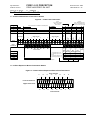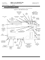
1
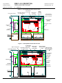
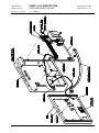
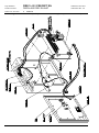
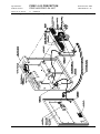
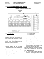
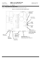
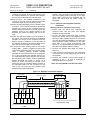
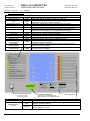
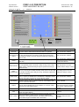
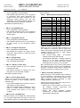
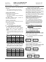
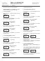
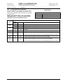
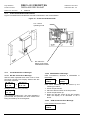
EQUIPMENT: FIRECLASS PRECEPT EN WRITTEN BY: RKP PUBLICATION: FIRECLASS PREC EN INST CHECKED BY: AP ISSUE No. & DATE: 0 APPROVED BY: JBJ 09/03/12 Precept EN Fire Detection/Alarm Panel & Precept EN Repeater Installation & Commissioning Manual PAGE 1 of 31 EQUIPMENT: FIRECLASS PRECEPT EN WRITTEN BY: RKP PUBLICATION: FIRECLASS PREC EN INST CHECKED BY: AP ISSUE No. & DATE: 0 09/03/12 List of Contents 1. LIST OF FIGURES ............................................... 2 2. LIST OF TABLES ................................................ 2 3. INTRODUCTION .................................................. 3 4. INSTALLATION AND COMMISSIONING OVERVIEW . 3 5. INTERNAL PANEL VIEWS .................................... 3 6. TYPICAL WIRING SCHEMATIC – 16 ZONE ............. 8 7. CIRCUIT CONNECTION DETAILS .......................... 9 7.1 2-16 ZONE MOTHERBOARD TERMINATION DETAILS ....................................................... 9 7.2 16 ZONE EXPANSION BOARD TERMINATION DETAILS ....................................................... 9 8. C1627 MOTHERBOARD FEATURES .................. 10 9. C1632 16 ZONE EXPANSION BOARD FEATURES ....................................................................... 11 10. POWER SUPPLIES ........................................... 11 10.1 VISUAL INDICATIONS ................................... 11 10.2 BATTERY DISCONNECT ............................... 11 10.3 32 ZONE PANEL POWER SUPPLY DETAILS ... 12 11. INSTALLATION ................................................. 13 11.1 ELECTRICAL SAFETY .................................. 13 11.2 INSTALLATION INSTRUCTIONS ...................... 14 11.2.1 PANEL INSTALLATION INSTRUCTIONS ...... 14 11.2.2 OPTIONAL C1631 REPEATER INTERFACE INSTALLATION ....................................... 15 12. COMMISSIONING .............................................. 16 12.1 INTRODUCTION ........................................... 16 12.2 COMMISSIONING CHECKLIST ....................... 16 12.3 COMMISSIONING PROCEDURE OVERVIEW .... 16 12.4 PRE-COMMISSIONING W IRING CHECK ......... 16 12.5 POWERING UP ............................................ 17 12.6 CONFIGURATION......................................... 17 12.6.1 BASIC DEFAULT CONFIGURATION ........... 17 12.6.2 SITE-SPECIFIC CONFIGURATION............. 17 12.7 COMMISSIONING PROCEDURE ..................... 17 12.7.1 ALARM CIRCUITS ................................... 17 12.7.2 ZONES .................................................. 17 12.7.3 CLASS CHANGE INPUT ........................... 18 12.7.4 FIRE AND FAULT ROUTING OUTPUTS ...... 18 12.7.5 FIRE PROTECTION CONTROL SIGNAL ...... 18 12.7.6 ANCILLARY INPUTS ................................ 19 12.7.7 ANCILLARY OUTPUTS ............................. 19 12.7.8 REPEATERS .......................................... 19 13. USER INDICATIONS .......................................... 20 14. USER CONTROLS ............................................ 21 15. OPERATING THE ENGINEER‟S FUNCTIONS ......... 22 15.1 ENGINEER‟S ZONE/OUTPUT CONFIGURATION PROCESS: .................................................. 22 15.2 ZONE OR OUTPUT CONFIGURATION ............. 22 15.3 TO RESTORE THE FACTORY DEFAULT CONFIGURATION FOR ZONES & OUTPUTS: ... 23 15.4 ENGINEER‟S ZONE/OUTPUT CONFIGURATION TIME-OUT W ARNING: .................................. 23 15.5 INVALID CONFIGURATION CONDITIONS: ........ 23 15.6 LIST OF CONFIGURATION DIL SWITCHES AND THEIR FUNCTIONS ....................................... 23 15.7 CONFIGURABLE OPTIONS VIA DIL SWITCH SELECTION ON REPEATER INTERFACE BOARD: ................................................................. 25 15.8 CONFIGURING THE FIRE ROUTING, FIRE PROTECTION AND FAULT ROUTING O/PS ..... 25 15.9 DISABLING THE EARTH FAULT MONITORING .. 25 16. CLOCK MODULE CONFIGURATION AND SETTING25 16.1 STANDARD MODULE ENGINEER MODE: ....... 25 16.1.1 TO ZERO THE ALARM COUNTER: ............ 25 16.1.2 TO ACCESS THE ENGINEER’S CLOCK MODULE EDIT FUNCTIONS ..................... 25 16.2 CONFIGURING THE CLOCK MODULE ............ 27 16.3 C1651 CLOCK MODULE PCB FEATURES .... 28 16.4 CLOCK MODULE ERROR MESSAGES ........... 28 16.4.1 WP DIL SWITCH ERROR MESSAGE: ....... 28 16.4.2 EEPROM ERROR MESSAGE:................ 28 16.4.3 ROM CHECKSUM ERROR MESSAGE: ..... 28 17. MECHANICAL, ELECTRICAL & ENVIRONMENTAL SPECIFICATION ............................................... 29 18. CONSTRUCTION PRODUCTS DIRECTIVE ............ 31 1. List of Figures FIGURE 1 – PRECEPT EN 2/4 ZONE INTERNAL VIEW ... 3 FIGURE 2 – PRECEPT EN 8/16 ZONE INTERNAL VIEW . 4 FIGURE 3 – PRECEPT EN 32 ZONE INTERNAL VIEW .... 4 FIGURE 4 – 2/4 ZONE PRECEPT EN PANEL - GENERAL ASSEMBLY (WITH OPTIONAL CLOCK MODULE) ...... 5 FIGURE 5 – 8/16 ZONE PRECEPT EN PANEL - GENERAL ASSEMBLY (WITH OPTIONAL CLOCK MODULE) ...... 6 FIGURE 6 – 32 ZONE PRECEPT EN PANEL - GENERAL ASSEMBLY (WITH OPTIONAL CLOCK MODULE) ...... 7 FIGURE 7 – TYPICAL W IRING DIAGRAM ...................... 8 FIGURE 8 – C1627 FIELD TERMINATION..................... 9 FIGURE 9 – C1632 16 ZONE EXPANSION BOARD FIELD TERMINATION .................................................... 9 FIGURE 10 – C1627 MOTHERBOARD LAYOUT .......... 10 FIGURE 11 – C1632 16 ZONE EXPANSION BOARD ... 11 FIGURE 12 – 32 ZONE PANEL POWER SUPPLY LAYOUT ....................................................................... 12 FIGURE 13 - REPEATER CONNECTION DIAGRAM ........ 15 FIGURE 14 – C1651 CLOCK MODULE PCB .............. 28 2. List of Tables TABLE 1 – MOTHERBOARD DELAY SWITCH SETTINGS 24 TABLE 2 – C1631 SETTING REPEATER QUANTITY .... 25 TABLE 3 – C1631 SETTING REPEATER ADDRESSES . 25 TABLE 4 – C1651 CLOCK MODULE DIL SWITCH AND LINK SETTINGS ................................................ 27 PAGE 2 of 31 EQUIPMENT: FIRECLASS PRECEPT EN WRITTEN BY: RKP PUBLICATION: FIRECLASS PREC EN INST CHECKED BY: AP ISSUE No. & DATE: 0 09/03/12 3. Introduction 4. Installation and Commissioning Overview The FIRECLASS Precept EN range of panels have been designed, manufactured and tested to meet the requirements of BSEN 54 Parts 2 & 4 and will provide the user with many years of reliable service. This document contains all the information necessary for the installation, commissioning and maintenance of the Precept EN range of panels and repeaters. This section lists the steps that are taken in designing, installing and commissioning a FIRECLASS Precept EN system. 1. Install all field wiring and equipment Refer to the Installation Guidelines in section 11.2 below Refer to the field device installation manuals 2. Install the panel NOTE: It is important to read this manual fully before commencing installation. Refer to the installation instructions in section 11.2 below The following supporting documentation is also available: Do not connect the field equipment at this stage. 3. Connect any repeaters (if applicable) FIRECLASS Precept EN Sales Literature FIRECLASS Precept EN Panel Application Guide Refer to the installation instructions in section 11.2 below FIRECLASS Precept EN User Manual Wiring Recommendations 4. Commission the panel Refer to Commissioning in section 12. 5. Internal Panel Views See Figures below: Figure 1 – Precept EN 2/4 Zone Internal View 3 x Enclosure fixing holes Removable chassis Secondary earth bar for cable screens Cable clip for incoming mains cable Mains warning / primary earth label Mains terminal block and primary earth connection Motherboard 1 2 3 Mains transformer R0 R1 R2 CEL C1631 ISSUE 0 SW1 C1631 repeater interface [ optional] Removable chassis 1 2 DELAY/ 4 MINUTES 8 Mains transformer Motherboard Batteries Batteries PAGE 3 of 31 EQUIPMENT: FIRECLASS PRECEPT EN WRITTEN BY: RKP PUBLICATION: FIRECLASS PREC EN INST CHECKED BY: AP ISSUE No. & DATE: 0 09/03/12 Figure 2 – Precept EN 8/16 Zone Internal View TB4 9 TB5 +1 0 - TB6 +1 1 TB7 TB8 +1 - +1 2ZONE 3 CIRCUITS CIRCUITS 2 3 + - + - - TB12 TB14 TB15 + 4 - TB16 AU X D.C. 0 24V V INPUTS TB17 OUTPUTS TB18 O/ + +1 6 TB19 C/ P FAULT ROUTING REPEATER B TB10 +1 5 1 A TB9 +1 4 + TB20 C/ + O/ P FIRE ROUTING C/ + TB21 O/ P FIRE PROTECTION P N/ RESEC T J1 7 Removable chassis 2 J2 0 DISPLA Y J 1 TB23 3 1 R 2 J 1 2 DELA MINUTE Y/ 4 S 5 5 8 7 7 ZONES CONFIG DELAY ZONES CONFIG DELAY O/PS 2 STAGE 8 8 Motherboard L 3 J18 B L 4 1 0 1 0 TEST BUZZER DISABLE LATCHED FAULTS 9 9 DELAYON EVAC ALARMS ONLY L 2 ZONAL ALARMS PULSE NON-ALARM ZONES SILENT ZONE 6 6 ORIG N1 SILENCE BEFORE RESET 1 4 4 ZONESM/S CONFIG 3 3 DELAYRESET ON AUTONON-LATCH CONFIG ZONES CONFIG I/S 2 SW INHIBIT F/P ON 2 NLZALARM SIL & DELAY 2 L 1 1 SW 1 1 Mains transformer ~ ~ 1 Motherboard R 0 R CEL C1631 ISSUE 0 SW 1 ZONE EXPANSION J2 0 J J 8 7 C1631 repeater interface [optional] RESE N/T O + 8- SC N + 7- J 6 + ALARM + 6- Mains terminal block and primary earth connection I/O EXPANSION TB3 ZONE CIRCUITS + 4- + 5- + 3- J1 7 + 2- J1 J1 J1 6 5 4 TB2 + 1- J1 J1 J1 2 1 0 TB1 4 EVA C 3 RST . CLAS S CHANG E DIS . 2 EVAC . BUZ . ACTIV E ZONE OUTPUTS 1 Mains warning/ primary earth label Cable clip for incoming mains cable SIL . Removable chassis Secondary earth bar for cable screens 3 x Enclosure fixing holes TB11 FS 1 - BATTERY FUSE BAT + T L 5 TB13 THER M Batteries Batteries Figure 3 – Precept EN 32 Zone Internal View +1 5 - TB1 4 TB1 5 + TB1 6 4 - TB1 7 TB1 8 O/ C P + FAULT /ROUTING +1 6 TB1 9 C/ + TB2 0 O/ P FIRE ROUTING S W1 1 2 3 C/ O/ P FIRE + PROTECTION R 0 R 1 R 2 1 0 1 0 SILENCE BEFORE RESET 1 DEL 2 MINUT AY/ 4 ES 8 ZONAL ALARMS PULSE NONALARM ZONES SILENT ZONE TEST BUZZER DISABLE LATCHED FAULTS FS 1 BATTERY FUSE TB1 1 - BA + TT TB1 3 THE RM L 2 L 3 L 4 L 5 J1 8B DISPL AY + 19 - TB 2 TB 3 TB 4 + 26 - J1 7 J 1 J2 0 TB2 3 1 2 3 4 5 6 7 8 9 1 2 3 4 5 6 7 8 9 L 1 ORI GN1 S INHIBIT F/P W2 ON NLZ DELAY ALARM SIL & RESET DELAY ON AUTO CONFIG NONLATCH I/S ZONES CONFIG ZONESM/S CONFIG ZONES CONFIG DELAY ZONES CONFIG DELAY O/PS 2 STAGE DELAY ALARMS ON EVAC ONLY + 18 - ZONE CIRCUITS + 20 + 21 - + 25 - N/ P RESC ET J 1 S W1 Mains transformer + 17 - TB 1 TB2 1 J 1 Motherboard B 1 A + TB1 2 earth connection J 1 TO MOTHERBOARD +1 4 + 8- TB1 0 ~ ~ +1 - +1 2 ZONE 3 CIRCUITS + 7- TB 9 SC N RES N/ ET O + 6- TB 8 7 +1 1 TB 7 Mains warning/ primary earth Mains terminal label block and primary 0 +1 0 - TB 6 J1 J1 J1 6 5 4 9 + 3- TB 5 J J J 8 7 6 + + 2- TB 4 REPEATER J1 J1 J1 2 1 0 + 1- TB 3 OUTPUTS I/O EXPANSION J1 4 INPUTS CEL C1631 ISSUE 0 3 TB 2 AUX D.C. 24V 0V ZONE EXPANSION J2 2 ALARM CIRCUITS 2 3 + - + - EV AC 1 TB 1 ZONE CIRCUITS + 4- + 5- EVA C. BU ACTI Z. VE ZONE OUTPUTS SI L. Removable chassis RS T. CLA CHAN SS GE DI S. Mains transformer 3 x Enclosure fixing holes Cable clip for incoming Secondary earth bar mains cable for cable screens + 27 - TB 5 + 28 - + 29 - + 22 - + 23 - + 24 - TB 6 TB 7 TB 8 + 30 - + 31 - + 32 - FI D1 C1631 repeater interface [optional] Removable chassis 17 -32 zone expansion board 1-16 zone Motherboard Batteries Batteries PAGE 4 of 31 EQUIPMENT: FIRECLASS PRECEPT EN WRITTEN BY: RKP PUBLICATION: FIRECLASS PREC EN INST CHECKED BY: AP ISSUE No. & DATE: 0 09/03/12 Figure 4 – 2/4 Zone Precept EN panel - General Assembly (with optional clock module) PAGE 5 of 31 EQUIPMENT: FIRECLASS PRECEPT EN WRITTEN BY: RKP PUBLICATION: FIRECLASS PREC EN INST CHECKED BY: AP ISSUE No. & DATE: 0 09/03/12 Figure 5 – 8/16 Zone Precept EN panel - General Assembly (with optional clock module) PAGE 6 of 31 EQUIPMENT: FIRECLASS PRECEPT EN WRITTEN BY: RKP PUBLICATION: FIRECLASS PREC EN INST CHECKED BY: AP ISSUE No. & DATE: 0 09/03/12 Figure 6 – 32 Zone Precept EN panel - General Assembly (with optional clock module) PAGE 7 of 31 PAGE 8 of 31 1 2 3 Zone O/Ps 4 1- 9+ 1+ 2- 3+ 3- 4- 5+ Zone Circuits 6+ - 2 - 5- Zone Circuits 4+ + 1 1A 2A - 6- 7+ 7- 8+ 8- Detector base with Schottky Diode 1+ 9 - 10 + 10 - 11 + 11 - 12 + 12 - 13 + 13 - 14 + 14 - 15 + 15 - 16 + 16 - 2+ Connect to Aux DC 24V + + + 1- + + + + 2- 3+ For Fire Routing and Fire Protection O/Ps: Volt free relay contacts shown in quiescent [de-energised] condition. For Fault Output: Volt free relay contacts shown in healthy [energised] condition. Connections: Connect to normally open or normally closed contact as required.[P= Pole, C= Closed, O = Open] Applied voltage must not exceed 30V DC. For Fault Routing O/P: Quiescent: 24V DC [nom] Active [fault]: 5V Connections: Observe correct polarity. [+ = Positive, - = Negative] When configured as volt-free changeover relays : For Fire Routing and Fire Protection O/Ps: Quiescent: 5V DC Active [fire]: 24V nom] When configured as monitored/powered outputs: 3- Alarm Circuits 2+ - - - - 3K9 resistor end-of-line device Inputs Outputs B 24V 0V O/+ C/- C/+ P O/- C/+ P O/- Upper terminal tier Fire and Fault Routing output wiring shown for the monitored/powered configuration N/O Lower terminal tier Relay local to fire routing equipment equipment P RST RST Field relay spec: Coil resistance - 2.6K to 4.5K Ohms Voltage 24V DC Nom [min 18V, max 30V] Fitted with suppression diode as shown. P Terminal identification notes: Cl/C = Class Change. B Act = Buzzer Active RST = Reset Repeater Wiring - see Figure 9 - Repeater connection diagram Scn N/C Repeater Sil Evac RST Cl/C Dis Evac BAct A 2k2 0.5W resistor Typical remote output wiring Aux DC Fault Routing Fire Routing Fire Protection Aux DC 4 - 24V 0V [Normally open switch contacts] Typical Input Circuit Wiring for Remote Silence, Evac, Reset & Class Change, Relay local to fault routing equipment equipment 4+ Typical Alarm Circuit Wiring Fire Routing, Fault Routing & Fire Protection O/P configuration - Output specification: Upper terminal tier Lower terminal tier 24V DC relay Typical zonal output wiring Manual call point with 680R resistor Typical Zone Wiring 22uF capacitor end-of-line device -observe polarity -ve EQUIPMENT: FIRECLASS PRECEPT EN WRITTEN BY: RKP PUBLICATION: FIRECLASS PREC EN INST CHECKED BY: AP ISSUE No. & DATE: 0 09/03/12 6. Typical wiring schematic – 16 Zone Figure 7 – Typical Wiring Diagram EQUIPMENT: FIRECLASS PRECEPT EN WRITTEN BY: RKP PUBLICATION: FIRECLASS PREC EN INST CHECKED BY: AP ISSUE No. & DATE: 0 09/03/12 7. Circuit Connection Details 7.1 2-16 Zone Motherboard Termination Details Figure 8 – C1627 Field Termination Precept Inputs: SIL = Silence alarms EVAC = Evacuate RST = Reset Grey fill indicates I/O available on selected panel Outputs: DIS = Disablement active EVAC = Evacuation active BUZ Active = Buzzer active 2 4 8 16/32 7 8 1 2 3 4 A B GND 6 EVAC 5 Repeater Buz Active 4 DIS 3 Class change 2 - + - + - + - + - + - + - + - + - + - + - + - + RST 4 EVAC 3 0V 2 SIL 1 1 Aux DC Alarm Circuits 24V Zone Circuits Zone O/Ps Outputs Reset N/C Inputs Lower terminal tier Upper terminal tier 16/32 Grey fill indicates I/O available on selected panel 7.2 16 Zone Expansion Board Termination Details Figure 9 – C1632 16 Zone Expansion Board Field Termination Zone Circuits 17 18 19 20 21 - + - + - + - + + 22 23 24 - + - + - + - Lower terminal tier Upper terminal tier - + - + - + - + + 25 26 27 28 - + - + - + 29 Zone Circuits PAGE 9 of 31 30 31 P 8 N/O 4 O/- Reset Fault Fire Fire Routing Routing Protection O/- = Normally Open or -ve O/+ = Normally Open or +ve P = Pole C/+ = Normally Closed or +ve C/- = Normally Closed or -ve 2 P Aux DC Precept O/- 16 C/+ 15 P 14 C/- 13 C/+ 12 Zone Circuits P 11 0V 10 O/+ 9 24 V - + - + - + - + - + - + - + - + 32 EQUIPMENT: FIRECLASS PRECEPT EN WRITTEN BY: RKP PUBLICATION: FIRECLASS PREC EN INST CHECKED BY: AP ISSUE No. & DATE: 0 09/03/12 8. C1627 Motherboard Features Figure 10 illustrates the motherboard features referred to elsewhere in the documentation. Figure 10 – C1627 Motherboard Layout Remote Inputs: Silence Alarms Evacuate Reset Zone Outputs 1-4 Aux DC Supply 24V & 0V Fire Routing Output Fault Routing Output Fire Protection Output Alarm Circuits [Marked with Active Polarity] Zone Detection Inputs J6,J7,J8 Fault Routing Output configuration links Aux Outputs: DISablement active EVACuate Active BUZzer ACTIVE Repeater Terminals: A,B, GND Reset Relay Output J10,J11,J12 Fire Routing Output configuration links Connector for C1632, Zone Expansion Board J14,J15,J16 Fire Protection Output configuration links J1 Display Connector C1631 Repeater Interface Secondary AC from transformer Configuration mode enabled LED indicator Configuration switches SW1/1 to SW1/10 FS1 Battery Fuse Battery Terminals Configuration switches SW2/1 to SW2/10 Battery Thermistor Terminals PAGE 10 of 31 Power Supply LED indicators: OUTPUT OK Battery/Charger Fault Charger Fault Mains Fault J18 Earth Fault Monitoring Link EQUIPMENT: FIRECLASS PRECEPT EN WRITTEN BY: RKP PUBLICATION: FIRECLASS PREC EN INST CHECKED BY: AP ISSUE No. & DATE: 0 09/03/12 9. C1632 16 Zone Expansion Board Features Figure 11 – C1632 16 Zone Expansion Board Connector for motherboard ribbon Detection zone terminals for zones 17 - 32 10. Power Supplies The Precept EN 2, 4, 8 and 16 zone panels produce dc power regulation directly on the C1627 motherboard. The Precept EN 32 zone panel has an off-board power supply via a dedicated PCB (C1652) contained within the enclosure of the fire alarm panel. For all panels, the output voltage is adjustable from 25V to 28.2V via a small trimmer potentiometer on the PCB. As the output voltage is factory set however, this should not be necessary. 10.1 Visual indications The following visual indications are provided: 1) A green „Output - OK‟ LED. This simply denotes that power is being supplied to the panel 2) A yellow „Batt/Charge Fault‟ LED denoting any one of the following conditions: a) Battery or associated wiring disconnected b) Battery fuse blown c) Low Battery voltage (15.7V ±0.4V) d) Battery and interconnection resistance is equal to or higher than: 1Ω - 4-zone panels 1Ω - All repeaters 0.6Ω - 8/16-zone panels 0.35Ω - 32-zone panels 3) A yellow „Charger Fault‟ LED („Internal Fault‟ LED on the C1652 PSU board) indicating any of the following: a) A mains fault exists (see below) b) Switching regulator or charger circuitry is malfunctioning c) Battery Fuse is blown 4) A yellow „Mains Fault‟ LED. This indicates that the mains voltage has failed or is less than the required minimum for correct operation of the power supply (80% of the rated voltage). Note: Fault indications do not become active for a minimum of 10 seconds after the fault has occurred. 10.2 Battery Disconnect 1) The supply provides a battery disconnect facility which disconnects the batteries when the battery terminal voltage falls below 19.5V. PAGE 11 of 31 EQUIPMENT: FIRECLASS PRECEPT EN WRITTEN BY: RKP PUBLICATION: FIRECLASS PREC EN INST CHECKED BY: AP ISSUE No. & DATE: 0 09/03/12 10.3 32 zone Panel Power Supply Details Figure 12 shows the layout of the 32 zone Precept EN panel power supply. Figure 12 – 32 Zone Panel Power Supply Layout Secondary AC Supply from Transformer 28V, 0V DC Power output Mains Fault Output Common Fault Output Battery connections Battery Thermistor connections DC supply output voltage adjustment potentiometer [factory set]. 4-way header for connector to 32 zone motherboard for DC power, common fault and mains fault LED indicators for: Mains fault, Internal Fault, Battery/Charge Fault, Output O.K. FS1 Battery Fuse [6.3A] PAGE 12 of 31 EQUIPMENT: FIRECLASS PRECEPT EN WRITTEN BY: RKP PUBLICATION: FIRECLASS PREC EN INST CHECKED BY: AP ISSUE No. & DATE: 0 09/03/12 11. Installation The control panel must be installed by suitably qualified engineers familiar with the installation of fire detection systems. In addition, it is recommended to refer to the following information: Current edition of the IEE wiring regulations. Current edition of BS5839-1 or the installation standards for the relevant country. Any specific site requirements. Any field device installation instructions. Any data sheet provided for the installation of Intrinsically Safe devices. Notes: The rating plate, containing essential electrical information is located inside the panel on the inside face of the door. The mains supply cable should be a minimum of 2 1mm copper protected by a 5A fuse. An appropriate lockable double pole disconnect device shall be provided as part of the building installation. This device must have a minimum contact gap of 3mm. 11.1 Electrical Safety WARNING: Read this section completely before commencing installation. Prior to commencing installation of the control panel, ensure that adequate precautions are taken to prevent damage to the sensitive electronic components on the display board and the control board due to electrostatic discharge. You should discharge any static electricity you may have accumulated by touching a convenient earthed object such as an unpainted copper radiator pipe. You should repeat the process at regular intervals during the installation process, especially if you are required to walk over carpets. The panel must be located in a clean, dry position, which is not subject to shock or vibration and at least 2 metres away from pager systems or any other radio transmitting equipment. The operating temperature range is 0ºC to 40ºC; maximum humidity is 95%. IMPORTANT NOTES ON BATTERIES: DANGER: Batteries are electrically Live at all times, take great care never to short circuit the battery terminals. WARNING: Batteries are often heavy; take great care when lifting and transporting batteries. For weights above 24 kilos, lifting aids should be used. highly corrosive substance, and presents significant danger to you and to anything else it touches. In case of accidental skin or eye contact, flush the affected area with plenty of clean, fresh water and seek immediate medical attention. Valve Regulated Lead Acid (VRLA) batteries are “low maintenance”, requiring no electrolyte topup or measurement of specific gravity. WARNING: Only clean the battery case with a cloth that has been soaked or dampened with distilled water. Do not use organic solvents (such as petrol, paint thinner, benzene or mineral spirits) or other materials that can substantially weaken the case. Do not use a dry cloth as this will generate static electricity, which in turn may lead to an explosion. WARNING: Avoid operating temperatures outside the range of -15C/5F to +50°C/122°F for float/standby applications. The recommended normal operating temperature is 20°C. HIGH TEMPERATURE will reduce battery service life. In extreme cases this can cause Thermal Runaway, resulting in high oxygen/hydrogen gas production and battery swelling. Batteries are irrecoverable from this condition and should be replaced. LOW TEMPERATURE will prolong battery life but reduce output capacity. DANGER: Do not incinerate batteries. If placed in a fire, the batteries may rupture, with the potential to release hazardous gases and electrolyte. VRLA batteries contain substances harmful to the environment. Exhausted batteries must be recycled. Return them to the battery manufacturer or take them to your Council waste disposal site for appropriate disposal. ELECTRICAL SAFETY: The volt-free relay contacts provided within the panel must not be used to directly switch any voltage that exceeds 50VAC or 75VDC. (Please also refer to relay rating data). This equipment requires a 230VAC supply. All installation work should be carried out in accordance with the recommendations of BS5839 Part 1 and the current edition of the IEE regulations by suitably qualified and trained personnel. THIS PANEL MUST BE EARTHED DANGER: Do NOT attempt to remove the battery lid or tamper with the internal workings of the battery. Electrolyte is a PAGE 13 of 31 EQUIPMENT: FIRECLASS PRECEPT EN WRITTEN BY: RKP PUBLICATION: FIRECLASS PREC EN INST CHECKED BY: AP ISSUE No. & DATE: 0 09/03/12 11.2 Installation Instructions 1. Carefully remove the control panel from the packing and lay the panel on a flat surface. 2. Open the door of the panel. 3. Locate the spares bag and check that the following items are present: Precept EN Precept EN Item 2/4 8/16/32 Mains Fuse T1AH250V 20mm 1 off Battery Fuse F2AL250V 20mm 1 off T3.15AH250V 20mm 1 off F5AL250V 20mm [8/16] F6.3AL250V 20mm [32] EOL capacitors for 22μF, 35V axial. 22μF, 35V axial. normal zone 2/4 off 8/16/32 off monitoring EOL resistors for 3K9 0.25W 3K9 0.25W alarm circuits and 4/8 off 12/20/36 off I.S. zones. Key Ref.: Key Ref.: Engineer‟s door 801 [Flat] 801 [Flat] keys 1 off 1 off Key Ref.: Key Ref.: Access Control 801 [Tubular] 801 [Tubular] keys 1 off 1 off Positive battery Red Red lead 1 off 1 off Negative battery Black Black lead 1 off 1 off Battery coupling Blue Blue lead 1 off 1 off Battery terminal Precept EN 32 N/A insulation boot only 11.2.1 Panel Installation Instructions 1. Disconnect the display ribbon cable from the motherboard header. 2. Disconnect the earth strap connecting the door and backbox via the spade terminal on the door. 3. Unscrew the hinge pin at the bottom of the door whilst supporting the door. Swing the bottom of the door clear of the backbox and pull the door away from the top hinge pin. 4. Place the door carefully to one side and replace the bottom hinge pin in the backbox. 5. Unscrew and remove the two lower chassis screws and only slacken the top two mounting screws. 6. Carefully lift the chassis upward to align the screw heads with the large holes in the chassis keyholes. Lift the chassis clear of the upper screws and rest the chassis in the bottom of the enclosure. Take care not to strain the wires that remain connected to the backbox. 7. Disconnect the earth strap connecting the backbox and chassis at the earth bar. 8. Disconnect the flying leads from the transformer to the mains terminal block and earth bar. 9. Remove the chassis from the enclosure and place carefully to one side. NOTE: The door and chassis both contain PCBs with sensitive and fragile electronic components on them. You must place them in an area that is clean, dry and dust-free, where they will not be damaged. You can place them inside the original packing box but you must ensure that sufficient soft packing is used to keep the door and chassis separated. 10. Identify the three indented holes in the backbox that are used to mount the enclosure. 11. Place the enclosure in the desired location and mark the position of the top indented hole. Remove the enclosure and fit a suitable fixing to the wall. Hang the enclosure from the top fixing point and ensure that it is level. Mark the locations of the other two mounting holes. 12. Remove the enclosure from the wall and fit suitable fixings to the two remaining mounting points. Fix the enclosure to the wall using all three mounting points. 13. Carefully remove the required knock-outs in the panel enclosure and gland all field wiring in place ensuring that the cable conductors are of sufficient length inside the enclosure. Ensure that all conductors are clearly labelled. DO NOT remove knock-outs from any unused cable entries. Any unused cable entries which are open must be sealed with a suitable plug (available separately). 14. Connect the earth drain wires of the field cabling to the brass earth bar positioned at the top of the backbox. Up to two drain wires may be connected to each terminal. 15. Ensure that continuity of any cable shield is maintained through to the last device on the circuit. The shield must only be connected to enclosure earth in the panel by using the earth bars provided. [Different requirements apply for the screen of data cable used for connecting repeaters - see 11.2.2 below]. 16. Connect the incoming protective earth conductor to the Earth terminal in the mains terminal block. This is the primary earth point and is labelled [also labelled E]. See Section 5. 17. Clear any dust and debris from inside the enclosure. 18. Connect the mains-in Live cable to the mains terminal block [L terminal] as indicated in section 5. 19. Connect the mains-in Neutral cable to the mains terminal block [N terminal] as indicated in section 5. 20. Secure the mains-in cable to the cable clamp adjacent the mains terminal using the cable tie supplied. NOTE: The clamp should be over the outer cable insulation. PAGE 14 of 31 EQUIPMENT: FIRECLASS PRECEPT EN WRITTEN BY: RKP PUBLICATION: FIRECLASS PREC EN INST CHECKED BY: AP ISSUE No. & DATE: 0 09/03/12 21. Reinstallation of the chassis is the reverse of removal. Reconnect all wires and ensure none are trapped between the chassis and backbox. Do not connect the field wiring at this stage. 22. Refit the door. The refitting procedure is the reverse of removal. Ensure that the earth strap and ribbon cable are reconnected correctly. 23. Place the left-hand battery into the bottom of the enclosure. The terminals should be positioned towards the centre of the enclosure and the battery should be adjacent to the left side of the backbox, fixed by the raised indents in the backbox, one above the battery and one to the right. 24. Place the right-hand battery into the bottom of the panel. The terminals should be positioned towards the centre of the enclosure and the battery should be adjacent to the right side of the backbox located by the raised indents in the back box above the battery and to the left. 25. Connect the black battery lead to the power supply “Batt -” [battery negative] terminal and connect the red battery lead to the power supply “Batt +” [battery positive] positive terminal [situated on the motherboard for the Precept EN 2/4, 8 and 16 panels and repeater panel or on the separate power supply board in the Precept EN 32 panel]. The location of the motherboard battery terminals are shown in Figure 10 & Figure 12. Fit the connector on the end of the black lead onto the negative (black) terminal of the left-hand battery. Fit the connector on the end of the red lead onto the positive (red) terminal of the right-hand battery. 26. Connect the blue battery lead between the positive (red) terminal of the left-hand battery and the negative (black) terminal of the righthand battery. Note that the batteries will not power the panel until the mains supply is energised. 11.2.2 Optional C1631 Repeater Interface Installation Warning: Observe anti-static precautions 1. Ensure that the panel and repeaters are powered down and the main and standby supplies are disconnected. 2. On the fire alarm panel and each repeater, remove the jumper link at J22 (adjacent to J9) and fit a C1631 repeater interface to connectors J13 and J9 located immediately to the left of the Zone Expansion ribbon connector on the righthand side of the C1627 motherboard. See Figure 10. The board should be held in place by the 12mm high plastic spacer provided. 3. Connect the RS485 data cable as shown in Figure 13. 4. If the repeater is powered from the panel then connect the Aux 24Vdc supply from the panel to the repeater. 5. Connect the repeater mains power supply (if required) to the L, N and E terminals as described above for the panel. Note: Use only RS485 screened data cable. Figure 13 - Repeater connection diagram EARTH BAR EARTH BAR Data Cable Screen A B Repeater GND B A Repeater GND Power Supply connections not shown. [Top right hand corner of C1626 motherboard] Repeater [max 5 off] [Top right hand corner of C1627 motherboard] Panel PAGE 15 of 31 EQUIPMENT: FIRECLASS PRECEPT EN WRITTEN BY: RKP PUBLICATION: FIRECLASS PREC EN INST CHECKED BY: AP ISSUE No. & DATE: 0 09/03/12 12. Commissioning 12.1 Introduction The following equipment should be available where possible to minimise commissioning time: i) VHF/UHF Portable Radio (for two engineers) ii) Multi-meter or equivalent 12.2 Commissioning Checklist 1. Before commissioning, the engineer should check the following: i) All field wiring has been inspected and tested in accordance with Manufacturer‟s wiring recommendations, current issues of BS5839:1 and BS7671 IEE wiring regulations. ii) All field cables are glanded into the control panel cabinet. iii) Detector bases are terminated but detector heads are not fitted. Any devices with electronic components are not fitted. Terminations to devices with electronic components should be linked through to maintain cable continuity. iv) Manual Call Points are not connected but cable is linked through to maintain continuity. v) No end-of-line devices (e.g. alarm circuit EOL resistor) are fitted in the field. 2. The following information should be available to the commissioning team: i) ii) iii) iv) Detection layout drawings. Wiring schematic diagram. Control Panel installation manuals. Installation manuals for all equipment connected to the system. v) Site specific configuration details. Experience has shown that tracing wiring faults on long circuits that are routed through risers etc. can be difficult without knowledge of the wiring route. It is recommended that the electrical installer be made available until basic wiring continuity is proven. A minimum of two persons (e.g. engineer and mate) is recommended for efficient commissioning. 12.3 Commissioning Procedure Overview Commissioning is broken in to 3 sections: i) Pre-commissioning wiring check. ii) Powering the panel up with no field wiring connected, configuring the panel in accordance with the site-specific requirements and carrying out a functional check. iii) Functional testing of all circuits and field devices to check each circuit and function in turn to ensure correct operation of the entire system. In this way any faults may be located quickly and accurately. The general procedures are as follows: 1. Alarm circuits should be checked first. The correct operation of each sounder should be checked for correct audibility as specified in BS5839:1, using the Evacuate function. 2. Detection zones should be commissioned next. The purpose is to establish the correct functioning of each device and checking for correct indication at the control panel. The panel responses as configured should be checked at this time. 3. All ancillary inputs and outputs should be commissioned and the functionality confirmed. 4. Fire protection signals should be tested. 5. Fire and fault routing signalling should be tested. WARNING: Before testing, the engineer must be aware both of the operation of all devices fitted to the auxiliary circuits and of the consequences of their operation. 12.4 Pre-Commissioning Wiring Check NOTE: This pre-commissioning wiring check procedure should be followed to test all wiring prior to specific commissioning of any detection, alarm and auxiliary circuits. 1. Ensure that no devices are connected to the detection zones and alarm circuits, but that the cables are linked through at the device locations to achieve a continuous circuit. 2. Ensure that the resistance of all cables to earth and between cores is at least 2M. Check the following: i) Positive to earth resistance is 2MΩ or greater. ii) Negative to earth resistance is 2MΩ or greater. iii) Positive to negative resistance is 2MΩ or greater. 3. Connect a wire link as the end-of-line device on each of the zones and alarm circuits. At the panel end, measure the resistance across the positive & negative ends of the cables for each of the circuits; ensuring the value does not exceed 20Ω. Remember to remove the wire links after the tests. PAGE 16 of 31 Correct polarity throughout all circuits must be maintained. Rectify any faults. All bells, detector heads and call points should now be connected and the correct end-of-line devices fitted. Use the spare end-of-line devices supplied and leave the EOL devices in the panel EQUIPMENT: FIRECLASS PRECEPT EN WRITTEN BY: RKP PUBLICATION: FIRECLASS PREC EN INST CHECKED BY: AP ISSUE No. & DATE: 0 09/03/12 terminals at this stage. Remember to remove any links fitted to detector bases. Be very careful to maintain correct polarity at each device. Warning: Intrinsically safe zone arrangement. End-of-line capacitors cannot be connected to zones monitoring Intrinsically Safe detection devices in hazardous areas. To do so will risk causing an explosion in the hazardous area. End-of-line resistors with a value of 3K9Ω must be used, which comply with the requirements laid down in the installation data sheets provided with the I.S. barrier and the I.S. fire detection devices. In order for detector head removal monitoring to function correctly when resistors are used as the end-of-line devices, any diodes in the detector bases that are in circuit when the detector head is removed must be disconnected. The panel must be configured to monitor Intrinsically Safe zones. The first device on an Intrinsically Safe zone must be an I.S. Zener Barrier or Galvanic Isolator. Detectors and Manual Call Points on the Safe side of the barrier are not permitted. To comply with the requirements of BS5839, all manual call points should be located in the zone cabling between the I.S. Barrier/Isolator and the first detector. Any manual call point or detector located on the “end-of-line” side of a detector will be rendered inoperative if the detector head is removed. 12.5 Powering up 1. Prior to powering up, the panel will have been installed in accordance with the installation instructions, all cabling will have been fully installed and tested, glanded into the panel enclosure but not connected to the panel terminals. The mains supply should be isolated externally to the panel. 2. Check the battery connections are correct. 3. Remove the mains supply fuse from the panel mains terminal block. Once the permit to energise the mains supply is in place, energise the mains and check the voltage and polarity are correct before replacing the panel fuse. 4. The panel will power up and if all the end of line devices are correctly terminated in the panel and the battery is OK, the panel should be silent, displaying only the Power Supply On indication. 5. Turn the Access Keyswitch to “1” and press the Test Display button. The panel should respond by lighting all indications and sounding the buzzer. This will continue for a few seconds after the button is released. 12.6 Configuration 12.6.1 Basic Default Configuration When first powered up, the Precept EN can be operated in the standard default mode without any additional configuration. The basic default mode is: All zones latching fire, non-delay, standard [nonintrinsically safe] Fire Routing, Fire Protection and Sounder outputs not delayed. 12.6.2 Site-Specific Configuration It is possible to tailor the functionality of the Precept EN fire alarm panel in line with site-specific requirements. Details of the site configurable options and the configuration process are provided in section 15.1. Charts are provided in the System Log Book for planning/recording the actual configuration. This configuration is not lost when the panel is powered down. 12.7 Commissioning Procedure After completion of the pre-commissioning wiring check, power-up and configuration, commission the circuits in line with the following guide. 12.7.1 Alarm Circuits 1. Remove the resistor from the first alarm circuit terminal and connect the first alarm circuit wiring to the terminals, observing correct polarity. Check that any alarm fault indications clear after a few seconds. 2. Use the Alarm Test facility [see Precept EN User Manual] or press Evacuate to operate the sounders. Check that all sounders connected to the alarm circuit operate. 3. Deselect the Alarms Test condition or if “Evacuate” was used, press silence alarms to stop the sounders operating. 4. Repeat steps 1 to 3 for the second and any subsequent alarm circuits. 12.7.2 Zones 1. Work logically and systematically through each zone. 2. Zone fault conditions: o Remove the end-of-line device from the zone 1 terminals and connect the cables of the zone 1 circuit to the panel terminals, observing the correct polarity. Check that any zone 1 fault indications clear after a few seconds. o Check the fault monitoring of the cable is correct by applying an open circuit then a short circuit at the end-of-line device (in the field). Check that the fault condition is indicated on zone 1 on the fire panel. PAGE 17 of 31 EQUIPMENT: FIRECLASS PRECEPT EN WRITTEN BY: RKP PUBLICATION: FIRECLASS PREC EN INST CHECKED BY: AP ISSUE No. & DATE: 0 09/03/12 o Remove the circuit faults, restoring the circuit to the healthy condition and confirm that the fault indication clears. 3. Zone fire conditions o Starting with the device nearest the panel, operate each manual call point and detection device on the zone in turn. o After operation of each device confirm: The fire indication is provided on the panel on the correct zone. The fire alarm devices operate correctly in line with the panel configuration. The Fire Routing and Fire protection outputs operate correctly in line with the panel configuration. o Press the Silence Alarms and the Reset buttons after each device test and check the alarm clears (Manual Call Points must be manually reset before resetting the panel). 4. Detector removal operation. o Remove the 1st detector along the zone cable [counting from the panel] on zone 1 and observe the following: The appropriate amber zone fault LED illuminates The internal buzzer sounds The fault relay operates o For non I.S. zone applications: Operate a manual call point between the detector that has been removed and the EOL capacitor. Check that the panel reacts as described above for a fire condition. Refit the detector, reset the manual call point, press the “Silence Alarms” button and then the “System Reset” button on the panel‟s display board and check that the control panel returns to its normal state. Repeat for all detectors on the zone. o For I.S. zone applications: Remove the 1st detector in the zone cable [counting from the panel] and operate a manual call point ensuring that the correct fire alarm condition is raised on the panel (assuming the installation complies with BS5839). Continue to check the operation of all other manual call points on the zone, resetting the manual call point and silencing/resetting the panel at each stage. Refit the detector and check that the control panel returns to its normal state. Continue to test each of the other detectors in turn, checking on each removal that: The appropriate amber zone fault LED illuminates The internal buzzer sounds. The fault relay operates. 5. Repeat steps 1 to 4, one zone at a time, until all the zones are commissioned. 6. Any faults that are found must be traced and rectified before proceeding. 12.7.3 Class Change Input 1. Connect the Class Change switch to the class change input on the motherboard. 2. Operate the class change switch and observe: i) The alarms sound for 5 seconds then stop. ii) The internal buzzer on the panel does not operate. iii) The internal buzzer on repeaters does not operate. 3. De-activate the class change switch 12.7.4 Fire and Fault Routing Outputs 1. Remove the resistor from the Fire Routing output circuit terminals and connect the field wiring to the terminals, observing correct polarity. Check that any fault indications clear after a few seconds. 2. To operate the output, initiate a fire condition on a zone. Check that the fire signal is received at the receiving station. Silence and reset the fire alarm panel to clear the output. 3. Remove the resistor from the Fault Routing output circuit terminals and connect the field wiring to the terminals, observing correct polarity. Check that any fault indications clear after a few seconds. 4. Initiate a fault condition on the fire alarm panel to signal a fault to the remote receiving station. 5. Confirm the receipt of the fault warning at the receiving station. 6. Open-circuit the output wiring of each circuit in turn, Confirm the fire alarm panel indicates Fire Routing and Fault Routing faults appropriately. 7. Reconnect the cabling and confirm the faults clear. 12.7.5 Fire Protection control signal 1. Ensure any fire protection equipment to be controlled via the Fire Protection output is locked off/safe before attempting any connection, testing or commissioning. 2. Remove the resistor from the Fire Protection output circuit terminal and connect the field wiring to the terminals, observing correct polarity. Check that any fault indications clear after a few seconds. 3. Initiate a fire condition on a zone to operate the output. Check that the fire signal operates the PAGE 18 of 31 EQUIPMENT: FIRECLASS PRECEPT EN WRITTEN BY: RKP PUBLICATION: FIRECLASS PREC EN INST CHECKED BY: AP ISSUE No. & DATE: 0 09/03/12 interface relay adjacent the fire protection equipment. 4. Open-circuit the field wiring and confirm that the fire alarm panel indicates Fire Protection output fault. 5. Reconnect the cabling and confirm the faults clear. 6. Final testing and commissioning of the loop through to the fire protection equipment, including test [simulated] activation of the equipment, should be carried out at the appropriate time in conjunction with the engineer responsible for the fire protection system. 12.7.6 Ancillary inputs Remote Silence Alarms, Reset and Evacuate inputs should each be tested by the activation of the remote equipment. The response should be verified for each signal. 12.7.7 Ancillary outputs The correct operation of equipment connected to the Zone Outputs, Disablement Active, Evacuate Active and Buzzer Active outputs should be verified in turn by initiating a fire condition on each of the appropriate zones; disabling/enabling a zone; operating the Evacuate button on the panel‟s display. 12.7.8 Repeaters 1. Power-up the Panel and then the Repeaters. Only the “Power Supply On” LEDs should be illuminated on the Panel and Repeaters. 2. At Repeater 1, turn the Access control switch to “1”, and press the “Evacuate” button. Check that the alarms operate and the internal buzzer operates on all repeaters. 3. Press the “Silence” button on the fire alarm panel. Check that the alarm circuits silence and the internal buzzer silences on all repeaters. 4. Repeat steps 2 and 3 for each repeater. 5. Operate a Manual Call Point on zone 1 and check for correct fire indication at each repeater. 6. Press the “Silence Alarms” button on a repeater and check that the alarms are silenced and the Zone 1 fire LED is constantly illuminated on all repeater panels. 7. Press the “Reset” button on a repeater and check that the panel and repeaters return to the quiescent state. 8. Repeat steps 5 to 7 for each zone and ensure “Silence Alarms” and “Reset” operate correctly from each repeater. 9. Set the DIL switches on the C1631 Repeater Interface card in the fire alarm panel OFF (No Repeaters). Check that all repeaters indicate a “Comms. Fault”. 10. Set the C1631 Repeater Interface card DIL switches in the fire alarm panel back to their previous settings and check that the repeaters return to normal. 11. Set the first repeater address to 0. Check that the panel indicates a “Repeater fault” and any additional repeaters display a steady “Comms fault” LED. 12. Set the first repeater address back to normal and check that the panel and repeaters return to normal. 13. Repeat steps 11 and 12 for any other connected repeaters. PAGE 19 of 31 EQUIPMENT: FIRECLASS PRECEPT EN WRITTEN BY: RKP PUBLICATION: FIRECLASS PREC EN INST CHECKED BY: AP ISSUE No. & DATE: 0 09/03/12 13. User Indications Description Power Supply On Colour Green Fire Red Fire Routing Active General Fault Power Supply Fault Red Yellow Yellow System Fault Yellow Earth Fault Fuse Fault Repeater Fault Sounder Fault/Disabled Sounder Test Fire Protection Fault/Disabled Fire Routing Fault/Disabled Fault Routing Fault/Disabled Yellow Yellow Yellow Yellow Yellow Yellow Yellow Yellow General Indicator Section Operating Condition Illuminates Steady for Mains or Standby power On. Flashes on any new fire alarm condition, changing to a steady indication on operation of Silence Alarms. Illuminates Steady when the Fire Routing Output is active. Flashes for any fault condition. Flashes for mains or standby power supply/charge fault Illuminates Steady to indicate Microcontroller or Memory Failure. Flashes to indicate Engineer‟s Configuration Mode active. Flashes for any positive or negative power supply earth fault. Flashes for any auxiliary supply fuse failure Flashes for any Repeater fault or repeater communication fault, Flashes for any sounder fault. Steady for sounders disabled. Illuminates Steady while sounder walk test is active. Flashes for a fault on the Fire Protection Output. Steady when Fire Protection Output is disabled. Flashes for a fault on the Fire Routing Output. Steady when Fire Routing Output is disabled. Flashes for a fault on the Fault Routing Output. Steady when Fault Routing Output is disabled. POWER SUPPLY ON 1 TEST DISPLAY EVACUATE FIRE 2 FIRE ROUTING ACTIVE GENERAL FAULT POWER SUPPLY FAULT 3 SILENCE/ RESOUND ALARMS ENABLE RESET DISABLE 4 5 6 SYSTEM FAULT 7 EARTH FAULT 8 FUSE FAILED SILENCE BUZZER REPEATER FAULT 9 TEST 10 11 SOUNDER FAULT/DISABLED DELAY ON/OFF/ OVERRRIDE SOUNDER TEST 12 13 SELECT FIRE PROTECTION FAULT/DISABLED 14 SELECT ON/OFF FIRE ROUTING FAULT/DISABLED 15 FAULT ROUTING FAULT/DISABLED O I 16 04:45:34 D/N ON Access Controls Keyswitch: O – Controls Locked I – Controls Unlocked Description Detection Zone Location Colour Red Yellow FIRE 1. THE RED ZONE INDICATOR WILL PULSE SHOWING THE LOCATION OF THE FIRE. 2. CARRY OUT THE REQUIRED FIRE DRILL. 3. TO SILENCE ALARMS PRESS SILENCE ALARMS. 4. TO RESET FROM THE FIRE CONDITION PRESS RESET. FAULT 1. DETERMINE THE CAUSE OF THE FAULT. 2. PRESS SILENCE BUZZER. 3. CALL YOUR SERVICE ENGINEER. SYSTEM FAULT THE PANEL IS INOPERATIVE. ARRANGE FOR ALTERNATIVE FIRE DETECTIN MEASURES. DISABLEMENT AND TEST 1. PRESS SELECT ON/OFF. THE LED WILL ILLUMINATE. 2. SELECT THE ZONE OR OUTPUT USING ↑ AND ↓. THE FAULT LED WILL PULSE. 3. PRESS DISABLE OR TEST. 4. TO RE-ENABLE, SELECT THE ZONE OR OUTPUT AND PRESS ENABLE. Clock Module [Optional]: Showing time and Day/Night ON Back light flashes for Clock Module fault. User Instructions Zone Location Indications Operating Condition Flashes when zone is in a fire condition, turning to steady on operation of Silence Alarms. Flashes when zone is in a fault condition. Illuminates steady when zone is disabled or in test. PAGE 20 of 31 EQUIPMENT: FIRECLASS PRECEPT EN WRITTEN BY: RKP PUBLICATION: FIRECLASS PREC EN INST CHECKED BY: AP ISSUE No. & DATE: 0 09/03/12 14. User Controls POWER SUPPLY ON 1 TEST DISPLAY EVACUATE FIRE 2 FIRE ROUTING ACTIVE GENERAL FAULT POWER SUPPLY FAULT 3 SILENCE/ RESOUND ALARMS ENABLE RESET DISABLE 4 5 6 SYSTEM FAULT 7 EARTH FAULT 8 FUSE FAILED SILENCE BUZZER REPEATER FAULT 9 TEST 10 11 SOUNDER FAULT/DISABLED DELAY ON/OFF/ OVERRRIDE SOUNDER TEST 12 13 SELECT FIRE PROTECTION FAULT/DISABLED 14 SELECT ON/OFF FIRE ROUTING FAULT/DISABLED 15 FAULT ROUTING FAULT/DISABLED O I 16 04:45:34 D/N ON FIRE 1. THE RED ZONE INDICATOR WILL PULSE SHOWING THE LOCATION OF THE FIRE. 2. CARRY OUT THE REQUIRED FIRE DRILL. 3. TO SILENCE ALARMS PRESS SILENCE ALARMS. 4. TO RESET FROM THE FIRE CONDITION PRESS RESET. FAULT 1. DETERMINE THE CAUSE OF THE FAULT. 2. PRESS SILENCE BUZZER. 3. CALL YOUR SERVICE ENGINEER. SYSTEM FAULT THE PANEL IS INOPERATIVE. ARRANGE FOR ALTERNATIVE FIRE DETECTIN MEASURES. DISABLEMENT AND TEST 1. PRESS SELECT ON/OFF. THE LED WILL ILLUMINATE. 2. SELECT THE ZONE OR OUTPUT USING ↑ AND ↓. THE FAULT LED WILL PULSE. 3. PRESS DISABLE OR TEST. 4. TO RE-ENABLE, SELECT THE ZONE OR OUTPUT AND PRESS ENABLE. Access Controls Keyswitch: O – Controls Locked I – Controls Unlocked Switch Functionality Button Availability Operates all sounders continuously and lights the RED LED next to Evacuate When controls are unlocked the button until the Silence/Resound Alarms button is operated When the sounders are operated, 1st press stops sounders. If a zone Silence/Resound is in fire, the General Fire LED and the Zonal fire LED will change When controls are unlocked Alarms from flashing to steady. 2nd press restarts the silenced sounders if a zone is in fire. When controls are unlocked and [if Clears the panel display, resets the zones, outputs and operates the Reset silence before reset is configured] reset relay. sounders are silenced. 1] Press to stop the buzzer sounding in fire or fault conditions. Always available. Silence Buzzer 2] In 2-Stage Delay Mode, with stage 1 delay running, press to start stage 2 delay, otherwise all delayed outputs operate when Stage 1 timer times out. 1] Press once to Enable the delay mode, lighting the adjacent delay on LED. Press again to disable the delay mode and turn off the LED Delay On/Off/Override 2] Overrides the delay when delay is running. All delayed outputs will operate immediately. Enables the USER SELECT feature [Select ↑, Select ↓] for selection of Select On/Off zones or outputs for disablement/re-enablement & Day/Night On/Off selection and setting current time on Clock Module if fitted. Press to illuminate all LEDs on the display and operate the buzzer. All Test Display indications remain active for approx 5 seconds. Also displays alarm count on Clock Module if fitted. When the panel is in the fire condition and the delay is running. 1] When controls are unlocked and delay period is not zero. 2] When the delay is running. When controls are unlocked Always available When controls are unlocked, the Select switch has been operated Enable and a zone or output has been selected. Disable Press to disable a zone or output selected via the User Select feature. As above. Press to initiate the One Man Test on sounders or zones as selected Test As above. via the User Select feature. Used to scroll the cursor indication through the zone and output fault When controls are unlocked and LEDs on the display to select a zone or output for disablement, Select ↑ Select ↓ the Select switch has been enablement or test. [LED illuminated when Select Mode is active]. operated. Also scrolls through Clock Module menu when fitted. Press to clear the disablement or test condition on a zone or output selected via the User Select feature. PAGE 21 of 31 EQUIPMENT: FIRECLASS PRECEPT EN WRITTEN BY: RKP PUBLICATION: FIRECLASS PREC EN INST CHECKED BY: AP ISSUE No. & DATE: 0 09/03/12 15. Operating the Engineer‟s functions 15.1 Engineer‟s Zone/Output Configuration Process: Various programmable configuration options associated with the zonal inputs and outputs can be enabled/disabled by operating the appropriate DIL switch located within the panel enclosure. These are: o Configure zones as delayed zones. o Configure zones for use with I.S. barriers/isolators. o Configure zones as latching/non-latching fire indication. o Configure zones to short circuit fire mode. o Configure outputs to be delayed. Note: Configure Machinery Space Zones feature is not used on the Precept EN panels. 15.2 Zone or Output Configuration 1. Select a programmable configuration mode: o Enable the controls on the display, by turning the Access Keyswitch on the panel display to the “1” position. o If the panel is in the fire alarm condition, silence the alarms and reset. o Open the panel door and locate the appropriate DIL switch on the motherboard [Config Non-latch Zones; Config I.S. Zones; Config Delay Zones; Config Delay O/Ps] and move the switch to the ON position. The CONFIG ENABLED LED on the motherboard will illuminate. The Panel‟s System Fault LED will flash and the buzzer will operate. The Select LED on the front of the display will pulse. Any standing fire or fault alarm indications and associated outputs will be inhibited. If active, the indications for evacuation, silence buzzer, delay on or disablement indications will clear. The panel will indicate the current status of the selected programmable configuration mode on the yellow fault/disabled LEDs on the Zones, Sounders, Fire Routing and Fire Protection outputs. A steady indication denotes that the zone/output is already configured to the selected mode. No indication denotes that the zone/output has not been configured to the selected mode. o Close the panel door to allow access to the buttons on the display. 2. Select a zone or output to be configured: o On the panel display, press the Select On/Off switch to enable the Select Mode. The Select LED will become steady and the panel buzzer will silence. A pulsing indication [cursor] will appear either on the Zone 1 Fault/Disabled LED or the Sounder Fault/Disabled LED/Test depending upon which configuration DIL switch is selected. o Use the Select ↑ and Select↓ buttons to scroll the cursor indication through the selectable options: For zonal configuration, through all zones sequentially in forward [Select↓] or reverse [Select ↑] sequence starting at zone 1. For Output Delay configuration, through Sounders, Fire Protection and Fire Routing outputs in forward [Select↓] or reverse [Select ↑] sequence starting at Sounders. 3. To change the configuration of a selected zone or output: With the cursor flashing on the selected zone or output: Operation of the ENABLE button will apply the configuration functionality to the selected zone/output causing the associated fault/disabled LED to provide a continuous indication. Operation of the DISABLE button will clear the configuration from the selection and restore normal operation. The fault/disabled LED will clear. By repeating steps 2 and 3, any number of zones [or outputs] can be configured. 4. To quit the programmable configuration mode: o To return the panel to normal operating mode applying the updated configuration: Open the panel door and return the selected Config DIL switch on the motherboard to the OFF position. The CONFIG ENABLED LED on the motherboard will clear, the panel buzzer will silence and the flashing System Fault indication and zone/output configuration status indications on the display will clear as will the cursor and the Select indications. Any current alarms, disablements, will be reindicated along with any active status indications [Delay on etc.]. o Close and lock the panel door. o Return the ACCESS Keyswitch to the “0” position to disable the controls on the display. IMPORTANT NOTE: WHILE THE PANEL IS IN THE ENGINEER‟S ZONAL/OUTPUT CONFIGURATION MODE, ALL ZONAL PAGE 22 of 31 EQUIPMENT: FIRECLASS PRECEPT EN WRITTEN BY: RKP PUBLICATION: FIRECLASS PREC EN INST CHECKED BY: AP ISSUE No. & DATE: 0 09/03/12 INPUTS ARE IN PERMANENT RESET AND OUTPUTS ARE INHIBITED - THE PANEL WILL NOT RESPOND TO ANY FIRE ALARM. 15.3 To Restore the Factory Default Configuration for Zones & Outputs: Open the panel door and locate the DIL switches SW1-4 to SW1-8 on the motherboard [Config Non-latch Zones; Config I.S. Zones; Config M/S Zones; Config Delay Zones; Config Delay O/Ps] and move the switch actuator on each switch to the On position. o The Config Enabled LED on the motherboard will flash. o The Panel‟s System Fault LED will flash and the buzzer will operate. o Any standing fault or disablement indications will clear. o It will not be possible to enter the Select Mode. Press the Disable button on the panel‟s display. Return DIL switches 1-4 to 1-8 to the OFF position. o The Config Enabled LED on the motherboard will clear. o The Panel‟s System Fault LED will flash and the buzzer will clear. o The factory default configuration [all zones as latching fire, non-delay, standard [nonintrinsically safe] will be restored and the Fire Routing, Fire Protection and Sounder outputs will no longer be delayed 15.4 Engineer‟s Zone/Output Configuration Time-out Warning: This feature is provided to prevent the panel being left in the Zone/Output Configuration condition. 1 minute after the last button press: o The panel buzzer will restart. o The Select LED will flash. o The System Fault LED will continue flashing. Press the Select On/Off button to continue with the configuration process otherwise quit the configuration process as described in 15.2 step 4. 15.5 Invalid Configuration conditions: Invalid condition: If 2 or more configuration switches on the motherboard are in the On position at the same time: o The Config LED on the motherboard will flash. o The System Fault and Select LEDs on the display will flash. o The fault relay will operate. o The panel buzzer will sound. o The Cursor indication will clear. o Configuration will be inhibited. To clear the invalid condition check the zone and output config switches [1/4, 1/5, 1/6, 1/7, 1/8] on the motherboard and ensure that only one is selected to ON. Invalid condition: Selecting any config mode switch [1/4, 1/5, 1/6, 1/7, 1/8] to the On position whilst the panel is in the fire condition. o The Config LED on the motherboard will flash. o The System Fault and Select LEDs on the display will flash. o The panel buzzer will sound. o The Cursor indication will clear. o Configuration will be inhibited. To clear the invalid condition, select the config switch to OFF. Reset the fire alarm condition before attempting the configuration process again. 15.6 List of configuration DIL switches and their functions SW 1/1 - Inhibit F/P on NLZ: Selects Fire Protection relay to operate or not to operate for a fire condition on any zone configured to non-latched mode. o OFF Fire Protection relay operates for a fire condition on any zone configured to nonlatched mode. o ON: Fire Protection relay does not operate for a fire condition on any zone configured to nonlatched mode. o [Not EN54 compliant function]. S/W 1/2 - Delay Alarm Sil & Rst: o OFF: Silence and reset available as normal. o ON: Prevents alarms being silenced or reset for a period of 3 minutes after a fire alarm condition occurs. [Not EN54 compliant function]. SW 1/3 - Delay On Auto: o OFF: Automatically turn off the delay mode once a day at the set time [the delay mode first being turned on manually]. o ON: Automatically turn the delay mode on once a day and off once a day at the set times. Requires optional clock module. SW 1/4 - Config Non-Latch Zones: o OFF: Configuration mode disabled. o ON: Enables selected zones to be configured to non-latching fire mode via the Engineer‟s Select feature. [Not EN54 compliant function]. PAGE 23 of 31 EQUIPMENT: FIRECLASS PRECEPT EN WRITTEN BY: RKP PUBLICATION: FIRECLASS PREC EN INST CHECKED BY: AP ISSUE No. & DATE: 0 09/03/12 SW 1/5 - Config I/S Zones: o OFF: Configuration mode disabled. o ON: Enables selected zones to be configured to Intrinsically Safe alarm thresholds and passive end of line fault monitoring via the Engineer‟s Select feature. [For use with appropriate I.S. barriers/Isolators, typically 330 Ohm zener barriers or galvanic isolators]. [Not EN54 compliant function.] 9 minutes. See Table 1 – Motherboard Delay Switch Settings Table 1 – Motherboard Delay Switch Settings Delay Duration Delay disabled 1 min 2 min 3 min 4 min 5 min 6 min 7 min 8 min 9 min 10 min SW 1/6 - Config M/S Zones: o OFF: Configuration mode disabled. o ON: Enables selected zones to be configured to short circuit fire mode via the Engineer‟s Select feature. SW 1/7 - Config Delay Zones: o OFF: Configuration mode disabled. o ON: Enables selected zones to be configured to Delay Mode via the Engineer‟s Select feature. SW 1/8 - Configure Delay O/Ps: o OFF: Configuration mode disabled. o ON: Enables the selection of outputs, via the Engineer‟s Select feature, to which the panel delay will apply. SW 1/9 - 2 Stage Delay: o OFF: Single Stage Delay Mode. o ON: Two Stage Delay Mode. SW 1/10 - Alarms on Evac Only: o OFF: Sounders operate on any fire condition including evacuate. o ON: Selects sounders to operate only when the panel is in the evacuate condition. Not EN54 complaint function. SW 2/1 - Silence Before Reset: Select type of reset mode. [Not EN54 compliant function. Provided to meet existing customer requirements]: o OFF: Reset available when panel is in the [unsilenced] fire or fault condition. o ON: Fire Condition Reset available only when panel is in Alarm Silenced condition. Fault reset available when panel is in the fault condition. SW 2/2 to 2/5 - Delay/Minutes: Sets the duration of the variable time delay element [i.e. the single stage delay and stage 2 of the two stage delay] in steps of 1 minute within the range 0- S/W 2/2 Off On Off On Off On Off On Off On Off On Off On Off On S/W 2/3 Off Off On On Off Off On On Off Off On On Off Off On On S/W 2/4 Off Off Off Off On On On On Off Off Off Off On On On On S/W 2/5 Off Off Off Off Off Off Off Off On On On On On On On On SW 2/6 - Enable Zonal Alarms: Select the type of sounder alarm response to a fire condition in conjunction with the Pulse Non Alarm Zones switch described below. [Not EN54 compliant function. Provided to meet existing customer requirements]: o OFF: General Alarm Mode - all sounders operate continuously until silenced. o ON: Zonal Sounder Mode - Sounder groups for zones not in the alarm condition may be selected, via the Pulse Non Alarm Zones switch [SW 2/7], to pulse or not to operate. Note: Zonal alarms on the 2/4 zone panel affects the standard sounder circuits on the motherboard. On the 8, 16 and 32 zone panels, it affects only the [future] expansion module sounder circuits. SW 2/7- Pulse Non Alarm Zones: Select the type of zonal sounder alarm response to a fire condition in conjunction with the Zone Alarms switch [SW 2/6] described above. [Not EN54 compliant function. Provided to meet existing customer requirements]: With the Zone Alarms switch [SW 2/6] in the On position [Zonal Sounder Mode]: o SW2/7 OFF: Zonal sounders for zone in the fire condition operate continuously until silenced. All others are silent. o SW2/7 ON: Zonal sounders operate continuously - all other sounders operate in pulsed mode until silenced. PAGE 24 of 31 EQUIPMENT: FIRECLASS PRECEPT EN WRITTEN BY: RKP PUBLICATION: FIRECLASS PREC EN INST CHECKED BY: AP ISSUE No. & DATE: 0 09/03/12 SW 2/8 - Silent Zone Test: Select sounder response in One Man [Detector] Test Mode: o OFF: Sounders operate once on each test. o ON: Sounders do not respond to a zone test. SW 2/9 - Buzzer Disable: Enable/disable panel fire/fault buzzer. o OFF: Buzzer is enabled. o ON: Buzzer is disabled. General Disablement LED illuminated. Not EN54 compliant function. Provided for commissioning purposes only. SW 2/10 - Latched Faults: When enabled, all fault conditions latch until the Reset switch is operated. o OFF: Non-latched faults. o ON: Latched faults. 15.7 Configurable Options via DIL switch selection on Repeater Interface Board: DIL switch SW1 on the C1631 Repeater Interface PCB is used to set the quantity of repeaters and the repeater addresses as follows: o To set the repeater quantity, set SW1 on the C1631 fitted to the fire alarm panel in line with Table 2. Table 2 – C1631 Setting Repeater Quantity Repeater Quantity 0 1 2 3 4 5 S/W 1/1 Off On Off On Off On S/W 1/2 Off Off On On Off Off S/W 1/3 Off Off Off Off On On o To set the addresses of the individual repeater panels, set SW1 on the C1631 fitted to each repeater panel in line with Table 3. Note that each repeater must have a different address. Table 3 – C1631 Setting Repeater Addresses Repeater S/W S/W S/W Address 1/1 1/2 1/3 0* Off Off Off 1 On Off Off 2 Off On Off 3 On On Off 4 Off Off On 5 On Off On * Note: Address 0 = repeater disabled. 15.8 Configuring the Fire Routing, Fire Protection and Fault routing O/Ps To configure the Fire Routing Output to volt-free relay contacts, remove links J10, J11 and J12. [These links are combined in a single block]. To configure the Fire Protection Output to volt-free relay contacts, remove links J14, J15 and J16. [These links are combined in a single block]. To configure the Fault Routing Output to volt-free relay contacts, remove links J6, J7 and J8. [These links are combined in a single block]. These links are located below the associated output in the top right hand section of the C1627 motherboard. See Figure 10. 15.9 Disabling the earth fault monitoring To disable the earth fault monitoring, remove the link J18 located towards the bottom right hand corner of the C1627 motherboard. See Figure 10. 16. Clock Module Configuration and Setting 16.1 Standard Module Engineer Mode: 16.1.1 To zero the Alarm Counter: This is an ACCESS LEVEL 4 operation. Open panel door and move the DIL switch 1, pole 2 on clock module PCB to the ON position. Return the DIL switch to the OFF position. 16.1.2 To access the Engineer‟s Clock Module Edit Functions Normal Time Display: HH:MM:SS HH:MM:SS or D/N ON D/N OFF Select Access Control key switch to position 1. Press the SELECT ON/OFF switch. Use the “Up/down” keys to scroll the cursor LED indication through the selectable options on the display LEDs until LCD backlight illuminates. Normal Time Display: HH:MM:SS HH:MM:SS or D/N ON D/N OFF To change the Day/Night Mode PAGE 25 of 31 Press SELECT ON/OFF. Delay On/Off Set Display: D/N ON D/N OFF or Change? Change? EQUIPMENT: FIRECLASS PRECEPT EN WRITTEN BY: RKP PUBLICATION: FIRECLASS PREC EN INST CHECKED BY: AP ISSUE No. & DATE: 0 09/03/12 On the rear of the Clock Module PCB, move the DIL switch 1, pole 1 on to the ON position. Pressing ENABLE (+) or DISABLE (-) toggles setting between D/N ON and D/N OFF. Press ENABLE (+) or DISABLE (-) to change SS to desired value (00 to 59) To set Day/Night Mode Off Time To set current time Press SELECT ↓, to access day/night OFF Time Set display: HH:MM:SS HH flashing OFF Time Press SELECT ↓, to access current Time Set display: HH:MM:SS HH flashing Time Set Press ENABLE (+) or DISABLE (-) to change HH to desired value (00 to 23) Press ENABLE (+) or DISABLE (-) to change HH to desired value (00 to 23) Press SELECT ↓, OFF Time Set display: HH:MM:SS MM flashing OFF Time Press SELECT ↓, Time Set display: HH:MM:SS MM flashing Time Set Press ENABLE (+) or DISABLE (-) to change MM to desired value (00 to 59) Press ENABLE (+) or DISABLE (-) to change MM to desired value (00 to 59) Press SELECT ↓, OFF Time Set display: HH:MM:SS SS flashing OFF Time Press SELECT ↓, Time Set display: HH:MM:SS SS flashing Time Set Press ENABLE (+) or DISABLE (-) to change SS to desired value (00 to 59) Press ENABLE (+) or DISABLE (-) to reset the SS value to zero. Press SELECT ↓, to exit back to Delay On/Off Set display: D/N ON D/N OFF or Change? Change? To set Day/Night Mode On Time Press SELECT ↓, to access day/night mode ON Time Set display: HH:MM:SS HH flashing ON Time Press ENABLE (+) or DISABLE (-) to change HH to desired value (00 to 23) Press SELECT ↓, ON Time Set display: HH:MM:SS MM flashing ON Time Pressing SELECT ↓ repeats the cursor/display changes as above. Pressing SELECT ↑ repeats the cursor/display changes as above in reverse. To exit Clock Module menu: Return WP DIL switch on TIMER MODULE to OFF position. Press ENABLE (+) or DISABLE (-) to change MM to desired value (00 to 59) Press SELECT ↓, ON Time Set display: HH:MM:SS SS flashing ON Time Press SELECT ON/OFF: Module switches off the LCD Backlight and exits configuration mode, Normal Time display: HH:MM:SS HH:MM:SS or D/N ON D/N OFF On completion of editing, return the Access Control Keyswitch to position 0. PAGE 26 of 31 EQUIPMENT: FIRECLASS PRECEPT EN WRITTEN BY: RKP PUBLICATION: FIRECLASS PREC EN INST CHECKED BY: AP ISSUE No. & DATE: 0 09/03/12 16.2 Configuring the Clock Module The Clock Module is configured by setting Link 1 and DIL switch 1, both located on the rear of the C1651 Clock Module PCB [accessed by opening the panel door]. NOTE: Link 1 & DIL switch 1 are only available at ACCESS level 4, i.e. they can only be set by suitably trained and qualified personnel. Table 4 – C1651 Clock Module DIL Switch and Link Settings Position Fitted Removed LINK 1 Function st 1 fire alarm time display mode Day/Night mode DIL Switch 1 Link 1 DIL Switch 1 1 1 Position Function Off On Off Clock Module menu configuration disabled Clock Module menu configuration enabled No effect 1 On No effect Off 2 Off Day/Night Mode and Fire Event Counter mode enabled Off 2 On Off On Day/Night Mode enabled, Fire Event Counter mode disabled. [To zero Fire Event Counter, select “On” momentarily then return to “Off.”]. On 2 Off st 1 alarm fire time and Fire Event Counter mode enabled st 1 alarm fire time enabled, Fire Event Counter mode disabled. On 2 On [To zero Fire Event Counter, select “On” momentarily then return to “Off.”]. PAGE 27 of 31 EQUIPMENT: FIRECLASS PRECEPT EN WRITTEN BY: RKP PUBLICATION: FIRECLASS PREC EN INST CHECKED BY: AP ISSUE No. & DATE: 0 09/03/12 16.3 C1651 Clock Module PCB Features Figure 14 llustrates the PCB features referred to elsewhere in the documentation Figure 14 – C1651 Clock Module PCB LK1 - Select operating mode DIL switch S1 Select config mode, reset/disable counter 16.4 Clock Module Error Messages 16.4.2 EEPROM Error Message: 16.4.1 WP DIL switch Error Message: WP DIL switch operated when timer is not in Timer Set Mode, Normal Time Display flashes with WP DIL switch message: HH:MM:SS HH:MM:SS or D/N ON D/N OFF Changes to (pulses every second): WP DILSW IS ON The backlight remains OFF. The panel indicates a general fault and prevents the clock module from being accessed by the user/engineer. Data inconsistency detected in EEPROM0 or EEPROM1: EEPROM 0 EEPROM 1 or ERROR ERROR Note: Both EEPROMs can be erased by the following procedure: 1. Power the panel down 2. Place the WP DIL switch in the ON position 3. Power the panel back up. 4. Return the WP DIL switch to the OFF position when the display is as described in 16.4.1 above. 16.4.3 ROM Checksum Error Message: Internal ROM Checksum failed: ROM FAIL ERROR PAGE 28 of 31 EQUIPMENT: FIRECLASS PRECEPT EN WRITTEN BY: RKP PUBLICATION: FIRECLASS PREC EN INST CHECKED BY: AP ISSUE No. & DATE: 0 09/03/12 17. Mechanical, Electrical & Environmental Specification Mechanical Specification Size [mm] Height: Width: Depth: Weight excluding batteries: Mains Input Specification Maximum Input Power: Protection: [Warning: Replace only with identical type & rating of BEAB or VDE approved fuse] Voltage: Cable requirements: Power Supply Output Specification Maximum Short Term Current Output (I max b) Maximum Short Term Current Output (I max b) Minimum Output Current (I min) Voltage Output, Mains On Maximum Current Output, Mains Failed Voltage Output, Mains Failed [* at full load] Max Ripple including switching spikes[full load/battery disconnected] (mV p-p) Output Voltage adjustment Output protection: Common fault output: Mains failed fault output: 2/4 zone Precept EN Panel 8 zone 16 zone 32 zone 2-8 zone Repeater 16 zone 32 zone 370 325 126 370 325 126 370 325 126 441 400 131 370 325 126 370 325 126 441 400 131 6.65Kg 7.05Kg 7.05Kg 9.35Kg 6.65Kg 6.65Kg 7.6Kg Precept EN Panel Repeater 2/4 zone 8 zone 16 zone 32 zone 2-8 zone 16 zone 32 zone 85W 165W 165W 240W 85W 85W 85W T1A H250V T3.15A H250V T3.15A H250V T3.15A H250V T1A H250V T1A H250V [1A antisurge] [3.15A antisurge] [3.15A antisurge] [3.15A antisurge] [1A antisurge] T1A H250V [1A antisurge] [1A antisurge] 230V AC +10%/-15% 2 Minimum of 1mm copper protected by a 5A fuse. Precept EN Panel Repeater 2/4 zone 8 zone 16 zone 32 zone 2-8 zone 16 zone 32 zone 1.5A 3A 3A 5A 1.5A 1.5A 1.5A 1.5A 3A 3A 5A 1.5A 1.5A 1.5A N/A (PSU is integrated into the motherboard) ZERO N/A (PSU is integrated into the motherboard) 26.5 - 28.6V (27.3V nominal) 1.5A 3A 3A 5A 1.5A 1.5A 20.0* 28.6V 20.0* 28.6V 20.0* 28.6V 20.0* 28.6V N/A 200 200 200 750 200 1.5A Factory Set Electronic current limiting N/A N/A N/A 25mA N/A N/A N/A N/A N/A N/A 25mA N/A N/A N/A PAGE 29 of 31 EQUIPMENT: FIRECLASS PRECEPT EN WRITTEN BY: RKP PUBLICATION: FIRECLASS PREC EN INST CHECKED BY: AP ISSUE No. & DATE: 0 09/03/12 Precept EN Panel Battery Specification Battery charger output: [Temperature compensated float charger] Repeater 2/4 zone 8 zone 16 zone 32 zone 2-8 zone 16 zone 32 zone 1.5A 3A 3A 5A 1.5 A 1.5 A 1.5 A 1 0.6 0.6 0.35 1 1 1 2 off PS1230 12V 3.4Ah 2 off PS1270 12V 7Ah 2 off PS12120 12V 12Ah 2 off PS12170 12V 17Ah 2 off PS1230 12V 3.4Ah 2 off PS1230 [2V 3.4Ah 2 off PS1230 12V 3.4Ah L = 133 W = 67 H = 60 HT = 66 L = 151 W = 65 H = 94 HT = 98 L = 151 W = 98 H = 94 HT = 100 L = 181 W = 76 H = 167 HT = 167 L = 133 W = 67 H = 60 HT = 66 L = 133 W = 67 H = 60 HT = 66 L = 133 W = 67 H = 60 HT = 66 F2A F5A L250V L250V 20mm fast 20mm fast blow glass blow glass fuse fuse F5A L250V 20mm fast blow glass fuse F6.15A L250V 20mm fast blow glass fuse F2A L250V 20mm fast blow glass fuse F2A L250V 20mm fast blow glass fuse F2A L250V 20mm fast blow glass fuse 28.6V 0.1V@-5C 26.5 V0.1V@ +40 C. Maximum internal resistance of battery & charger circuit: (Ri max) (Ω) Battery type: POWERSONIC [Warning: Replace only with identical battery] Battery size (mm): W HT H L Battery circuit protection: [Warning: Replace only with identical type & rating of fuse] Mains failed fault battery current: 45mA 45mA 45mA 55mA 40mA 40mA 40mA Mains failed alarm battery current: 80mA 80mA 80mA 90mA 75mA 75mA 75mA Environmental Specification All Panels Operating temperature: -5ºC to 40ºC Operating humidity: 5% to 95% PAGE 30 of 31 EQUIPMENT: FIRECLASS PRECEPT EN WRITTEN BY: RKP PUBLICATION: FIRECLASS PREC EN INST CHECKED BY: AP ISSUE No. & DATE: 0 09/03/12 18. Construction Products Directive 0086 Control Equipment Ltd Hillcrest Business Park Cinder Bank Dudley West Midlands DY2 9AP United Kingdom. 09 0086-CPD-555921 EN54-2 Control and indicating equipment for fire detection and fire alarm systems for buildings Provided options: Outputs to fire alarm devices. Output to fire alarm routing equipment. Outputs to Fire Protection Equipment - Output type B Output to fault warning routing equipment. Test condition. Alarm Counter. Delays to Outputs EN54-4 Power supply equipment for fire detection and fire alarm systems for buildings PAGE 31 of 31