1
AVEVA
TM-1830
Everything3D™ 2.1
AVEVA&Everything3D™
(2.1)Guide
Migration
Interoperability
Draw
AVEVA Everything3D™ 2.1
Migration & Interoperability Guide
This page is intentionally left blank
Copyright © 2015.
AVEVA Solutions Limited and its subsidiaries.
All rights reserved.
2
www.aveva.com
AVEVA Everything3D™ 2.1
Migration & Interoperability Guide
Revision Log
Date
Revision
16.10.2015
0.1
26.11.2015
27.11.2015
Description
Author
Reviewed
Approved
Issued for Review
SB
-
-
0.2
Reviewed
SB
P.Dev
-
1.0
Released with AVEVA E3D™ 2.1
SB
P.Dev
P.Dev
Updates
Change highlighting will be employed for all revisions. Where new or changed information is presented section
headings will be highlighted.
Suggestion / Problems
This manual provides documentation relating to products to which you may not have access or which may not
be licensed to you. For further information on which products are licensed to you please refer to your licence
conditions.
Visit our website at http://www.aveva.com
Disclaimer
1.1 AVEVA does not warrant that the use of the AVEVA software will be uninterrupted, error-free or free from
viruses.
1.2 AVEVA shall not be liable for: loss of profits; loss of business; depletion of goodwill and/or similar losses;
loss of anticipated savings; loss of goods; loss of contract; loss of use; loss or corruption of data or information;
any special, indirect, consequential or pure economic loss, costs, damages, charges or expenses which may
be suffered by the user, including any loss suffered by the user resulting from the inaccuracy or invalidity of
any data created by the AVEVA software, irrespective of whether such losses are suffered directly or indirectly,
or arise in contract, tort (including negligence) or otherwise.
1.3 AVEVA's total liability in contract, tort (including negligence), or otherwise, arising in connection with the
performance of the AVEVA software shall be limited to 100% of the licence fees paid in the year in which the
user's claim is brought.
1.4 Clauses 1.1 to 1.3 shall apply to the fullest extent permissible at law.
1.5 In the event of any conflict between the above clauses and the analogous clauses in the software licence
under which the AVEVA software was purchased, the clauses in the software licence shall take precedence.
Copyright © 2015.
AVEVA Solutions Limited and its subsidiaries.
All rights reserved.
3
www.aveva.com
AVEVA Everything3D™ 2.1
Migration & Interoperability Guide
Copyright Notice
All intellectual property rights, including but not limited to, copyright in this Training Guide and the associated
documentation belongs to or is licensed to AVEVA Solutions Limited or its affiliates.
All rights are reserved to AVEVA Solutions Limited and its affiliates companies. The information contained in
this Training Guide and associated documentation is commercially sensitive, and shall not be adapted, copied,
reproduced, stored in a retrieval system, or transmitted in any form or medium by any means (including
photocopying or electronic means) without the prior written permission of AVEVA Solutions Limited. Where
such permission is granted, AVEVA Solutions Limited expressly requires that the Disclaimer included in this
Training Guide and this Copyright notice is prominently displayed at the beginning of every copy that is made.
Licenses issued by the Copyright Licensing Agency or any other reproduction rights organisation do not apply.
If any unauthorised acts are carried out in relation to this copyright work, a civil claim for damages may be
made and or criminal prosecution may result.
AVEVA Solutions Limited and its affiliate companies shall not be liable for any breach or infringement of a
third party's intellectual property rights arising from the use of this Training Guide and associated
documentation.
@AVEVA Solutions Limited 2015
Trademark Notice
AVEVA™, AVEVA Everything3D™, AVEVA E3D™, [AVEVA Tags], Tribon and all AVEVA product and service
names are trademarks of AVEVA Group plc or its subsidiaries
Use of these trademarks, product and service names belonging to AVEVA Group plc or its subsidiaries is
strictly forbidden, without the prior written permission of AVEVA Group plc or AVEVA Solutions Limited. Any
unauthorised use may result in a legal claim being made against you.
Fluent is a trade mark of Microsoft Corporation. The Fluent user interface is licensed from Microsoft
Corporation by AVEVA and use of the Fluent trade mark is strictly forbidden
All other trademarks belong to their respective owners and cannot be used without the permission of the
owner.
Copyright © 2015.
AVEVA Solutions Limited and its subsidiaries.
All rights reserved.
4
www.aveva.com
CONTENTS
1
Introduction ............................................................................................................................ 9
Introducing AVEVA Everything3D™ 2.1 ......................................................................................... 9
The Migration & Interoperability Guide ........................................................................................ 11
Using this Guide ........................................................................................................................ 11
AVEVA Experience ......................................................................................................................... 11
2
AVEVA Everything3D™ 2.1 ................................................................................................. 13
Workstation Configuration ............................................................................................................ 13
Graphics Cards ............................................................................................................................... 14
Graphical Performance .............................................................................................................. 15
Server Configuration ...................................................................................................................... 15
Prerequisite for this Release (Products) ...................................................................................... 16
AVEVA Licensing™ 2.0.0 .......................................................................................................... 16
AVEVA Client Cache Service™ 1.0.5 ....................................................................................... 16
AVEVA Catalogue 2.1.0 ............................................................................................................ 17
Microsoft® Software .................................................................................................................. 17
Environment Variables ................................................................................................................... 18
Network ............................................................................................................................................ 18
Install ................................................................................................................................................ 18
AVEVA Everything3D™ – Projects 2.1 ......................................................................................... 19
AVEVA Sample Laser Data 1.1 ................................................................................................. 19
AVEVA Everything3D™ – Documentation 2.1 ............................................................................. 20
Entering AVEVA Everything3D 2.1 ............................................................................................ 20
3
Project Migration .................................................................................................................. 23
Migrating projects from AVEVA PDMS or Hull & Outfitting 12.0 ............................................... 23
AVEVA PDMS 12.0 AVEVA PDMS 12.1 .............................................................................. 23
AVEVA Hull & Outfitting 12.0 AVEVA Hull & Outfitting 12.1 ................................................ 23
Preparing an AVEVA PDMS or Hull & Outfitting 12.1.SP4 Project ............................................ 24
Marine Projects (Hull data) in AVEVA E3D 2.1 ......................................................................... 24
Preparing an AVEVA Everything3D 1.1 project ........................................................................... 24
AVEVA Catalogue and AVEVA Administration ............................................................................ 25
Customer PML & .NET Applications ............................................................................................. 25
4
Model Data ............................................................................................................................ 27
Structural ......................................................................................................................................... 27
Section Conversion ................................................................................................................... 28
Catalogue – Joints & Fittings ..................................................................................................... 29
Catalogue – Profiles .................................................................................................................. 30
Adding Joint & Fitting Images .................................................................................................... 32
Stairs, Ladders & Handrails ....................................................................................................... 34
Grids ................................................................................................................................................. 35
Ship & Plant Grid Conversion .................................................................................................... 35
Supports .......................................................................................................................................... 37
Database Updates ..................................................................................................................... 38
Supports Application Defaults ................................................................................................... 40
Template Data ........................................................................................................................... 41
Model Data Upgrade ................................................................................................................. 47
Support Designer Access .......................................................................................................... 47
Piping ............................................................................................................................................... 48
Sloping Pipes ............................................................................................................................. 48
Piping & Supports ...................................................................................................................... 50
Laser................................................................................................................................................. 50
Preparing for the HyperBubble .................................................................................................. 51
Compare / Update ........................................................................................................................... 51
5
Draw Data ............................................................................................................................. 53
Module Definition ............................................................................................................................ 53
Draw Transformation ...................................................................................................................... 53
Sheets ........................................................................................................................................ 54
Library Elements ........................................................................................................................ 55
Copyright © 2015.
AVEVA Solutions Limited and its subsidiaries.
All rights reserved.
5
www.aveva.com
AVEVA Everything3D™ 2.1
Migration & Interoperability Guide
Thumbnails ................................................................................................................................ 56
Refreshing overlays ................................................................................................................... 57
Modification of Library elements .................................................................................................. 58
Representation Rules & Styles .................................................................................................. 58
Label & Symbols ........................................................................................................................ 58
Visual Styles .............................................................................................................................. 59
Visual Layers ............................................................................................................................. 60
Plot Styles .................................................................................................................................. 60
Reference Grids in Draw ................................................................................................................ 61
General ADP.............................................................................................................................. 61
Area-Based ADP ....................................................................................................................... 62
3.4.2
The Isometric ADP..................................................................................................................... 63
Using a Marine Project with Draw ................................................................................................. 63
Draw System Defaults ............................................................................................................... 63
Drawing Database Storage ....................................................................................................... 63
Transformation of a Marine Drafting Drawing (incl. SDB File & Picture File) ............................ 64
5.5.3.7
D ............................................................................................................................................. 67
Marine Transform Configuration File ......................................................................................... 70
6
Compatibility & Interoperability .......................................................................................... 73
Compatibility with other AVEVA Products ................................................................................... 73
Interoperability - AVEVA PDMS or Hull & Outfitting 12.1.SP4.................................................... 74
Project Setup ............................................................................................................................. 74
Model Data ................................................................................................................................ 75
Outfitting Applications ................................................................................................................ 76
Hull Data .................................................................................................................................... 76
Reports ...................................................................................................................................... 76
Draw Data .................................................................................................................................. 76
AVEVA Administration 1.4.0 .......................................................................................................... 77
New Database Types ................................................................................................................ 78
Draw Module.............................................................................................................................. 78
Dynamic Database Sets ............................................................................................................ 78
Multi-write Dictionary & Property Databases ............................................................................. 78
Flexible Explorer ........................................................................................................................ 78
Unit Sets .................................................................................................................................... 78
AVEVA Global 3.2.1 ........................................................................................................................ 79
AVEVA Clash Manager 12.1 ........................................................................................................... 79
7
Customisations .................................................................................................................... 81
Use of PML & C# in AVEVA E3D 2.1 ............................................................................................. 81
General Considerations ................................................................................................................. 81
Environment Variables .............................................................................................................. 81
PMLLIB, PMLUI and CAF_UIC_PATH Path ............................................................................. 82
Core .dlls .................................................................................................................................... 83
Forms & Menus ............................................................................................................................... 83
Form Layout............................................................................................................................... 83
Sliding Forms ............................................................................................................................. 83
Form Title & Icon ....................................................................................................................... 83
3D View Form Borders .............................................................................................................. 83
Modules with Ribbon Menus ......................................................................................................... 84
Customising Ribbon Menus with PML ....................................................................................... 85
PML Add-in files......................................................................................................................... 85
Other Considerations ................................................................................................................. 86
Applications .................................................................................................................................... 86
AVEVA PDMS Draft & AVEVA Marine Drafting Customisations ................................................ 86
Accessing DRAW 2D Views ...................................................................................................... 86
Accessing the Draw Browser ..................................................................................................... 87
Use of :CDLimits ........................................................................................................................ 87
PML Object for Sections ............................................................................................................ 87
Marine Drafting .......................................................................................................................... 87
Module Switching ........................................................................................................................... 87
Writing PML code to work in both PDMS & AVEVA E3D ............................................................ 88
Copyright © 2015.
AVEVA Solutions Limited and its subsidiaries.
All rights reserved.
6
www.aveva.com
AVEVA Everything3D™ 2.1
Migration & Interoperability Guide
The interface to main bar menu and tool bar functions ............................................................. 88
Changes to environment variables ............................................................................................ 89
Use of Lists which have been replaced by Collections in AVEVA E3D .................................... 89
Changes to form layout ............................................................................................................. 89
Use of resource files for Icons ................................................................................................... 89
PML code setting view properties .............................................................................................. 89
Changes to PML TABSET gadgets ........................................................................................... 89
Appendix A Migration from PDMS 12.0 to 12.1 ....................................................................... 91
Upgrade overview ...................................................................................................................................... 91
DBUpgrade command.............................................................................................................................. 91
Database Version Control ........................................................................................................................ 92
Global ....................................................................................................................................................... 92
The Upgrade Process .............................................................................................................................. 93
Locking the Project ................................................................................................................................... 93
Extract Hierarchies ................................................................................................................................... 94
International characters (Unicode) ........................................................................................................... 94
Units of measure ........................................................................................................................................ 95
Schematics functions ............................................................................................................................... 95
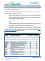
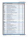
Appendix B Details of Sample Project Changes .................................................................... 97
ACP Project ................................................................................................................................................ 97
APS Project .............................................................................................................................................. 101
AMS Project .............................................................................................................................................. 106
Appendix C Forming Structural Joint & Fitting Images ....................................................... 109
Colours ..................................................................................................................................................... 109
Setting up a Joint in Model ..................................................................................................................... 110
Setting up a Section Fitting in Model .................................................................................................... 110
Setting up the 3D View ............................................................................................................................ 111
Setting the Auto Colours rules and Translucencies ............................................................................ 112
Taking the Screenshot ............................................................................................................................ 115
Naming the Image .................................................................................................................................... 115
Copyright © 2015.
AVEVA Solutions Limited and its subsidiaries.
All rights reserved.
7
www.aveva.com
AVEVA Everything3D™ 2.1
Migration & Interoperability Guide
This page is intentionally left blank
Copyright © 2015.
AVEVA Solutions Limited and its subsidiaries.
All rights reserved.
8
www.aveva.com
CHAPTER 1
1 Introduction
This document is intended to provide an overview of the migration process to AVEVA Everything3D™ 2.1 and
will highlight project considerations ahead of the successful implementation of the product.
Introducing AVEVA Everything3D™ 2.1
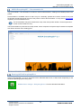
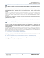
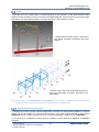
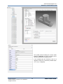
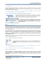
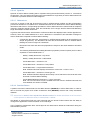
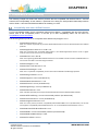
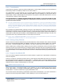
AVEVA Everything3D™ 2.1 (AVEVA E3D™ 2.1) is an innovative new flagship 3D design product from AVEVA
covering the needs of Plant industries. AVEVA E3D 2.1 also introduces the capability to display, interact with
and draw Hull models produced in AVEVA Marine.
AVEVA E3D 2.1 provides a platform that enables lean construction principles to be adopted, increasing quality
and speed of execution throughout the entire project. This is achieved through advanced usability for all design
tasks which improves productivity by utilising latest technologies and best in class User Experience to enable
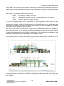
innovative and ever more efficient project execution processes. This is demonstrated by the clean and intuitive
user interface of the product that encourages graphical centric modelling and interaction.
: Hull Model in AVEVA E3D 2.1.
Copyright © 2015.
AVEVA Solutions Limited and its subsidiaries.
All rights reserved.
9
www.aveva.com
AVEVA Everything3D™ 2.1
Migration & Interoperability Guide
AVEVA E3D 2.1 is based upon a proven platform of technologies used to support a wider family of products;
supporting common capabilities such as multi-user, distributed and concurrent access to the design model,
and the comparison and update of information. This allows global teams to collaborate in building fully detailed
models, from which construction-ready drawings and BOMs can be automatically generated
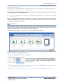
AVEVA E3D 2.1 contains the following principal modules:
Model
- An interactive 3D design environment.
Draw
- Facilitates the production of scaled, annotated drawings from the 3D Model.
IsoDraft
- Used in the production of piping isometrics.
As part of an integrated product solution, AVEVA E3D 2.1 may integrate with AVEVA Engineering and
Schematics products. The Piping Integrator feature has been redesigned to bring the 3D Design - P&ID
checking task to the daily workflow of a Piping designer. Further, AVEVA E3D 2,1 may be integrated with
AVEVA NET, epitomised by the Design in Context feature that allows the direct interrogation of the AVEVA
NET Dashboard in the Model and Draw environment.
The Model module provides enhanced access to project Design database and functions. The 3D graphics,
introduced at AVEVA E3D 1.1 are based on Microsoft DirectX, delivering a faster and clear graphic. AVEVA
E3D 2.1 introduces a redesigned structural application that places the model at the centre of design workflows.
Another primary development at AVEVA E3D 2.1 is the provision of a redesigned Supports application that
promotes an efficient and intuitive design workflow across different locations.
New innovation with laser data, utilising the immersive living Point Cloud capability of AVEVA HyperBubble™
will deliver project benefits, especially in brownfield projects. Powerful 2D drafting also allows the inclusion of
Laser data, removing the need to remodel existing Digital Assets.
System administration and configuration, together with catalogue and specification capabilities, are provided
by the separate AVEVA Administration™ and AVEVA Catalogue™ products respectively. AVEVA Catalogue
has been updated at this latest release and introduces a new user interface that is aligned in design with
AVEVA E3D 2.1.
Copyright © 2015.
AVEVA Solutions Limited and its subsidiaries.
All rights reserved.
10
www.aveva.com
AVEVA Everything3D™ 2.1
Migration & Interoperability Guide
AVEVA E3D 2.1 has been designed from the outset to be compatible with AVEVA PDMS and Hull & Outfitting
12.1.SP4 and it uses the same database and data management technology, enabling the two to be used in
conjunction on operational projects.
The Migration & Interoperability Guide
The aim of the Migration & Interoperability Guide is to provide an overview of the main differences between
AVEVA E3D 2.1 and AVEVA PDMS and Hull & Outfitting 12.1.SP4. It includes the project data migration
process between the two products and highlight the interoperability of the two products on a project.
This guide should be useful to administrators who wish to migrate an AVEVA PDMS or Hull & Outfitting project,
including those who wish to operate on projects in a mode where both products are in use. Customers who
are still using earlier releases of AVEVA PDMS and Hull & Outfitting should also read the latest editions of the
12.0 & 12.1 User Bulletins, as supplied with those releases to migrate project data to 12.1.SP4 prior to AVEVA
E3D 2.1.
Using this Guide
Certain text styles are used to indicate special situations throughout this document.
Button clicks are indicated by bold turquoise text.
Additional information notes and references to other documentation will be indicated in the styles below.
Additional information
Refer to other documentation
Example files or inputs will be in the courier new font.
AVEVA Experience
In addition to the migration of a project and the data to AVEVA E3D 2.1, it is also important to consider the
users of the product and their adaption to the functionality provided in order to realise an efficient design
workflow. This adoption is aided by an intuitive AVEVA E3D 2.1 user interface and workflows; designed with
the user and the graphical model at the centre of the process.
In addition AVEVA Experience™ (http://www.aveva.com/experience) provides an effective and easily
accessible way to gain hands-on experience of AVEVA E3D, wherever the user is located. For employers, it
makes it easier to train and upskill engineers and designers.
Once registered, the user will have the opportunity to go through an extensive set of training modules on core
aspects of AVEVA E3D, including training exercises and 'how-to' videos. These modules will highlight the key
differences between AVEVA PDMS and AVEVA E3D. The user will also be able to work with a Cloud-hosted
deployment of AVEVA E3D, including a sample set of project data.
Copyright © 2015.
AVEVA Solutions Limited and its subsidiaries.
All rights reserved.
11
www.aveva.com
AVEVA Everything3D™ 2.1
Migration & Interoperability Guide
This page is left intentionally blank
Copyright © 2015.
AVEVA Solutions Limited and its subsidiaries.
All rights reserved.
12
www.aveva.com
CHAPTER 2
2 AVEVA Everything3D™ 2.1
The AVEVA Everything3D™ 2.1 (AVEVA E3D™ 2.1) release, usually supplied by download from a secure
website, self-installs using standard Microsoft installation procedures. Please contact your local AVEVA office
if a DVD installation is required. As found with other AVEVA products, the release is typically installed to
individual PCs with a Microsoft Windows operating system, with the license server and file installed to a
networked Microsoft Windows server. In addition, the project data is typically located on a separate server.
AVEVA E3D 2.1 is a full release that may be run alongside and in conjunction with AVEVA PDMS and Hull &
Outfitting 12.1.SP4 (Fix Release 28 onwards).
AVEVA E3D 2.1 may also be used in conjunction with other products in the AVEVA product portfolio –
please refer to Chapter 6 Compatibility & Interoperability.
AVEVA E3D 2.1 requires the use of AVEVA Catalogue and AVEVA Administration: these are distributed and
installed with it, but are licensed separately and may also be used for AVEVA PDMS, Hull & Outfitting,
Engineering and Schematics products.
Workstation Configuration
The following configuration is recommended in the use of AVEVA E3D 2.1. A 64 bit operating system is
required for the installation of AVEVA Everything3D™ 2.1 and for the visualisation and use of laser data in the
application.
Operating System(s)
Windows® 7 Professional or Enterprise + Service Pack 1 *1.
Windows® 8.1*2.
Microsoft .NET Framework 4.0*3.
(Supplied with AVEVA E3D 2.1 and installed if necessary).
Processor Type / Speed
Intel x86 or x64 compatible - CPU with high performance in each processor core.
Memory
8 GB of high speed RAM
A full installation requires approximately 1GB of drive space.
Hard Disk Storage
In addition, extra capacity is usually required for local storage and data; this may be
used for the database cache where the Database Cache Service is employed.
The use of two SATA-300 RAID HDDs is recommended where projects are stored on
the local machine. The product has also been verified with solid state HDDs.
Display
High resolution widescreen display recommended (1920 x 1200); dual screens also
supported. Minimum resolution 1280 x 1024.
NVIDIA Quadro, AMD FirePro™ or similar.
Graphics Card
Please refer to Section 2.2 Graphics Cards for further information.
NTFS
File System
For information on conversion to NTFS, please see http://technet.microsoft.com/enus/library/bb456984.aspx.
*1 Please note that a Windows Platform Update (Windows 7 SP1 and Windows Server 2008 R2 SP1) is a pre-requisite for accurate 2D
rendering (for example Text graphics) in the 3D canvas (http://support.microsoft.com/kb/2670838 ).
*2 AVEVA does not support the installation of E3D 2.1 software and\or Projects on to disk volumes with Short\8.3 file name format disabled.
Please ensure that Short\8.3 file name format is enabled on all relevant volumes before installation. Please refer to Knowledge Base item
5702 for details.
Copyright © 2015.
AVEVA Solutions Limited and its subsidiaries.
All rights reserved.
13
www.aveva.com
AVEVA Everything3D™ 2.1
Migration & Interoperability Guide
*2 AVEVA E3D 2.1 has been tested with Microsoft .NET Framework 4.0 with the following fix: http://www.microsoft.com/enus/download/details.aspx?id=3556. This fix is mandatory for the use of the Design in Context Feature.
Microsoft .NET Framework 4.5 Fix 2 has been tested with AVEVA E3D 2.1. The fix release is required to ensure the correct visualisation
of AVEVA E3D Draw 2.1 print dialog.
For further information regarding IT Configuration please contact the local AVEVA Support Office.
Recommended / supported hardware and software configurations are constantly subject to review;
please consult the AVEVA support web pages for the latest recommendations.
Graphics Cards
AVEVA E3D 2.1 requires 3D graphics hardware, capable of running DirectX 11, to ensure optimum
performance for both design and drafting. DirectX 11 is included as an integral part of the Windows 7 & 8.1
operating systems.
AVEVA strongly recommends that appropriate hardware is used for AVEVA E3D 2.1. If appropriate graphics
hardware is not detected on entry, AVEVA E3D 2.1 may still be used but a warning will be given and certain
graphical effects, including use of laser data, limited.
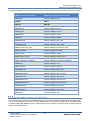
Following extensive testing of current market Graphics Cards and AVEVA E3D 2.1, a recommended
configuration is summarised in the table below.
Desktop
Graphics Card
DirectX Support
Laptop
NVIDIA® Quadro® K2000 or K2200.
NVIDIA® Quadro® K2000M or K2100M.
AMD FirePro™ W4100.
AMD FirePro™ 4000M.
DirectX 11 (Shader Model 5.0).
DirectX 11 (Shader Model 5.0).
Users using only AVEVA Catalogue or AVEVA Administration could consider a lower specification
graphics card such as a NVIDIA Quadro K620 (Desktop) or NVIDIA® Quadro® K1100M (Laptop).
Where laser data is utilised, the Graphics Card memory allocation is an important consideration as this
is further exploited in the visualization and manipulation of laser data (incl. HyperBubble™). Note that the
system will post an error message on entering the HyperBubble where the GPU memory is less than
1GB.
AVEVA strongly recommends that clients should test their chosen card or laptop in their own environment
before purchase.
Availability and support of graphics cards changes frequently; a full updated list of graphics cards that
have been verified with AVEVA E3D 2.1 is available via the IT Configuration area of the AVEVA Support
Site (http://support.aveva.com).
Copyright © 2015.
AVEVA Solutions Limited and its subsidiaries.
All rights reserved.
14
www.aveva.com
AVEVA Everything3D™ 2.1
Migration & Interoperability Guide
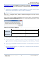
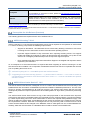
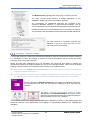
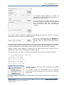
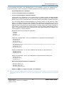
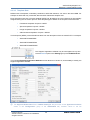
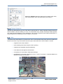
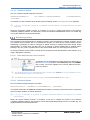
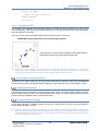
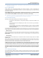
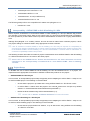
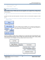
To ensure the optimal performance of the graphical memory, i.e. when utilising laser data, it is recommended
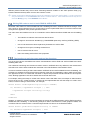
that the Physical Processor is altered (where employing a NVIDIA graphics card).
Using the NVIDIA Control Panel, setting a
GPU allows an increase in PhysX
processing and may improve overall
performance.
In the example here the PhysX processor
has been set to the NVIDIA Quadro
K2100M graphics card.
Graphical Performance
To ensure optimum graphical performance, and in addition to any Graphics Card specified, the workstation
used for AVEVA E3D 2.1 must conform to a reasonably high specification. To aid this specification, AVEVA
E3D 2.1 has been verified with 3DMark® (www.3dmark.com). A measure of overall system performance, the
score includes CPU, RAM etc.
Following verification with AVEVA E3D 2.1, a recommended 3DMark score is summarised in the table below.
Please note that the rating may vary from machine to machine depending on hardware specification and
software installed. The recommended scores are therefore indicative only.
3DMark®
Combined Score
Desktop
Laptop
130,000
70,000
Note: Laptop score is an average score across a number of laptop hardware specifications. Desktop score based on System information:
Processor Intel(R) Xeon(R) CPU E5-1603 v3 @ 2.80GHz, Installed Memory 8.00GB, 64-bit Operating System.
Server Configuration
The following configuration is recommended in the use of AVEVA E3D 2.1 with a server configuration. A 64
bit operating system is required for the installation of AVEVA Everything3D™ 2.1.
Operating System(s)
Processor Type / Speed
Memory
Windows Server 2008 R2 + Service Pack 1.
Windows Server 2012 R2.
Microsoft .NET Framework 4.0*1.
(Supplied with AVEVA E3D 2.1 and installed if necessary).
Intel x86 or x64 compatible - Modern architecture multiple core processors
recommended (AVEVA E3D 2.1 has been verified using a Server Machine with 4 core
CPUs).
16 GB RAM.
Additional RAM increases the caching capability and thereby the performance.
Hard Disk Requirements
The amount of disk space should be configured according to the customer's
requirement based on the number and size of projects (incl. supporting laser data).
To secure data and improve performance, the use of RAID 0+1 or 5 storage is
recommended; 15k rpm drives are preferred.
Copyright © 2015.
AVEVA Solutions Limited and its subsidiaries.
All rights reserved.
15
www.aveva.com
AVEVA Everything3D™ 2.1
Migration & Interoperability Guide
NTFS
File System
For information on conversion to NTFS, please see http://technet.microsoft.com/enus/library/bb456984.aspx
Gigabit Ethernet (GbE) LAN. 64-bit capable network adapter. The network should
provide at least 1 Gb/sec for each workstation. Two or more network cards are
recommended for increased performance and redundancy.
Network
*1 AVEVA E3D 2.1 has been tested with Microsoft .NET Framework 4.0 with the following fix: http://www.microsoft.com/enus/download/details.aspx?id=3556. This fix is mandatory for the use of the Design in Context Feature.
Microsoft .NET Framework 4.5 Fix 2 has been tested with AVEVA E3D 2.1. The fix release is required to ensure the correct visualisation
of AVEVA E3D Draw 2.1 print dialog.
Prerequisite for this Release (Products)
The following products are required for the use of AVEVA E3D 2.1.
AVEVA Licensing™ 2.0.0
AVEVA Licensing™ 2.0 or later and an appropriate License File is required for the operation of AVEVA E3D
2.1. AVEVA Licensing 2.0 provides the following improvements:
Support for Windows 8.1 and Windows Server 2012 thereby allowing customers to move their
Licensing Server to these later versions of the Microsoft operating systems.
Improved support facilities to help customers when reporting licensing issues. This support
bundle will enable the customer to gather all relevant files and information in a zip file so that
AVEVA can investigate problems and provide an improved support response.
Error messaging has been improved to aid AVEVA Support to investigate and respond to issues
reported by our customers.
As a consequence of the enhancements it is required that when migrating to AVEVA Licensing 2.0 a new
format license file is installed. It is an important consideration that the new license is requested and received
prior to updating the license server.
AVEVA Everything3D™ 2.1 does NOT operate with AVEVA Flexman.
If upgrading from AVEVA Licensing System 1.1.1, please install Fix release 1.1.1.3 in order to correct an
uninstall defect in that release. Once this has been done version 1.1.1.3 can be uninstalled and replaced
with later versions.
AVEVA Client Cache Service™ 1.0.5
The AVEVA Client Cache Service is designed for use on a LAN or WLAN network with full connectivity to the
Database files and can make a considerable improvement to Dabacon database performance. The use of the
Service is strongly recommended for all multi-user projects. The AVEVA Client Cache Service has been
developed to produce an improved performance when reading data over ‘high’ latency networks by minimizing
traffic.
The AVEVA Client Cache Service stores a copy of the read project data on the local disk which improves
performance where there is repeated reading of project data across a computer network. The service operates
by a data request being sent to the local Cache folder to retrieve the required Data (Database Page). If the
data is not within the Cache folder, a Data Request is sent across the network to the central server to retrieve
the required data. Likewise, data that is unchanged since it was previously read is retrieved from the local
Cache whereas Data that has changed in the Database must be read again from the central Database file.
Similarly, data that must be written to a Database file must still be written to that identified file.
Copyright © 2015.
AVEVA Solutions Limited and its subsidiaries.
All rights reserved.
16
www.aveva.com
AVEVA Everything3D™ 2.1
Migration & Interoperability Guide
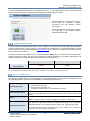
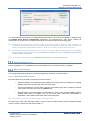
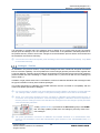
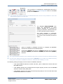
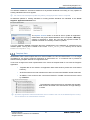
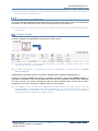
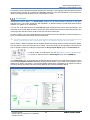
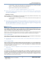
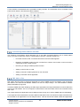
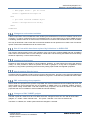
The AVEVA Client Cache Service is installed with AVEVA E3D 2.1 and may be configured or disabled using
the AVEVA Cache Service Configuration application. The prompted form, seen above, enables an
Administrator to configure the caching threshold level to avoid the local hard drive being filled.
The Default is to stop caching on the Hard Drive on becoming 80% full. When full, data is continued to
be delivered where already cached but no further data is cached until more space is made available. The
Cache persists data locally between sessions – thereby, very often, the start-up will be quicker.
To ensure the performance benefits of the service are realised, Microsoft Message Queuing (MSMQ)
must be enabled. This is achieved using the Windows Components feature of Windows Control Panel
> Add or Remove Programs.
For full details, please refer to the AVEVA Everything3D™ 2.1 Installation Guide.
AVEVA Catalogue 2.1.0
AVEVA Catalogue™ 2.1 is installed as part of the AVEVA E3D 2.1 install and is fully compatible.
Microsoft® Software
The following Microsoft products are required to support the operation of AVEVA E3D 2.1.
2.4.4.1 Microsoft Office & Fonts
Microsoft Office 2010 (and later) is required for some functions:
Optimum operation of the AVEVA Design Platform GUI requires Arial Unicode MS font, supplied
with Microsoft Office and also with Microsoft Office Visio.
The layout and display of forms and the general user interface may also be adversely affected
if the screen font size is not set to the smallest size.
Microsoft Office Excel import utilities in AVEVA E3D 2.1 require “.NET Programmability Support”
enabled when Office is installed. This can be found under “Advanced customization of
applications” and installs the Microsoft.Office.Interop.Excel.dll.
AVEVA E3D 2.1 has been verified with Microsoft® Office 365.
Microsoft Office Visio 2010 (Standard edition, 32-bit) or later is required where AVEVA Schematic Model
Viewer is used in conjunction with AVEVA E3D 2.1.
Copyright © 2015.
AVEVA Solutions Limited and its subsidiaries.
All rights reserved.
17
www.aveva.com
AVEVA Everything3D™ 2.1
Migration & Interoperability Guide
2.4.4.2 Microsoft Internet Explorer
Internet Explorer 8 or later is required to support AVEVA E3D 2.1 e.g. the Model and Draw Design in Context
feature.
2.4.4.3 Microsoft .NET Framework
AVEVA E3D™ 2.1 uses Visual Studio 2010 and .NET 4.0 SP1 for .NET Customisation.
Please note that serialized settings (of the user interface configuration) are now saved in the following location
on Windows 7 and 8.1:
C:\Users\<username>\AppData\Local\Aveva\AVEVA Everything3D\2.1
Environment Variables
AVEVA E3D 2.1 relies on the use of environment variables for various aspects of configuration, notably the
location of folders for project databases and user workspace.
When setting up a user’s environment, please bear in mind that Write access is required for folders such as
AVEVA_DESIGN_USER and AVEVA_DESIGN_WORK. The installer uses default locations, for both the
program files and these data folders, that are different from those used for PDMS. These were chosen to work
better on Windows 7 and 8.1; additional dialogs enable the user to control them better.
The defaults are:
Work files
C:\Users\<username>\AppData\Local\Temp\
User files
C:\Users\Public\Documents\AVEVA\USERDATA\
Environment variables are usually set up for AVEVA E3D by the program initialisation (.INIT) file when running
interactively or by using a batch (.BAT) file.
Note that at AVEVA E3D 2.1 an optional feature is available whereby a customer may remove all the
Project evars from the corresponding bat files apart from <proj>000 and ID (required to display project in
Login form). On selecting the project and entering AVEVA E3D 2.1, the start-up process will look to the
project and set up any required environment variables. Where an evar is already set, the start-up process
will leave that untouched, thus avoiding any unnecessary changes.
Network
AVEVA E3D 2.1 is best run on a network offering Internet access.
The system will by default be set up to access the latest online version of the documentation from the AVEVA
website. It is possible instead to install the documentation locally. It may be downloaded from the AVEVA
Support website, currently: AVEVA Everything3D - Documentation 2.1.
Install
Installations using setup.exe will install to C:\Program Files (x86)\AVEVA\Everything3D2.1.0 by
default. The individual .msi files will use the drive with most free space by default.
It is important that any files, including configuration files or sample data, that need to be updated by users are
accessible for read, write etc. so they are not by default installed with the software. This is particularly important
when installing in Program Files due to the introduction of User Account Control (UAC). In particular, this
makes it important to ensure that files that need to be written are accessible by users without Administrator
privileges. This applies to folders specified by environment variables such as AVEVA_DESIGN_WORK and
AVEVA_DESIGN_USER. The AVEVA Everything3D™ installer has been designed to allow the separate
definition of suitable folders, with different defaults.
Copyright © 2015.
AVEVA Solutions Limited and its subsidiaries.
All rights reserved.
18
www.aveva.com
AVEVA Everything3D™ 2.1
Migration & Interoperability Guide
It is not recommended that any combination of AVEVA products are installed in the same folder because
AVEVA does not guarantee runtime compatibility between Separate Products on different release cycles,
and the uninstall of one of them subsequently damaging the other.
For further details, please refer to the AVEVA Everything3D™ 2.1 Installation Guide. This may be
accessed from the start screen of the installation process or found within the E3D210 release folder.
AVEVA Everything3D™ – Projects 2.1
As part of the install process for AVEVA E3D 2.1, a variety of standard model projects may be installed and
thereafter used in the product. The projects are also available as a separate download available here: AVEVA
Everything3D™ - Projects.
The sample projects have been extended, enhanced and renamed but wherever data matches the
previous (AVEVA PDMS and Hull & Outfitting) sample model data, the same reference numbers and
database numbers are used to ensure compatibility.
Note that all databases are in Unicode format (as found in the AVEVA 12.1 Series) so are not compatible
with the AVEVA 12.0 series or earlier.
A file, for example APS_Project_description.pdf, is included in each project folder giving brief details of the
purpose and data included in that project. The Catalogue Project (ACP) provides example component data
and specifications (Component Data). All data in the projects are provided as sample data only and should be
verified prior to production use.
Major project differences at AVEVA E3D 2.1 include:
The main catalogue sample project (formerly MAS) is now called ACP (AVEVA Catalogue
Project).
The main sample data projects (formerly SAM and MAR) are now called APS (AVEVA Plant
Sample) and AMS (AVEVA Marine Sample).
Sample drawings are in the new Draw format and Draw project libraries have been extended to
support new Draw capabilities.
The catalogue has been enhanced for structural, supports and bolt holes
Additional data has been added to support the use and demonstration of Supports, Structural
and Laser.
The AVEVA sample projects are regularly revised. Please check the AVEVA Support Site (AVEVA
Everything3D™ Fix Release History) frequently for updates.
A detailed list of changes is included in Appendix B Details of Sample Project Changes.
AVEVA Sample Laser Data 1.1
AVEVA Laser Sample Data 1.1 is available for use with AVEVA E3D 1.1 for the purpose of familiarisation with
the extensive laser functionality available, including the new HyperBubble™ technology.
The data was captured during a project to survey the Eaton Training Centre in Houston utilizing the latest
laser scanning technology from Dot Product, FARO, Leica, Riegl, Trimble and Z+F. The various datasets
have been prepared for consumption using LFM Software technology, the only laser scan data
processing solution available that is able to combine such a broad selection of data formats into a single
dataset.
AVEVA and LFM would like to thank Eaton for granting permission to utilize this data with our customers.
Eaton’s training facility focuses on industrial applications with over 5000 products installed on the mockup site and is available for a variety of training applications year-round.
Copyright © 2015.
AVEVA Solutions Limited and its subsidiaries.
All rights reserved.
19
www.aveva.com
AVEVA Everything3D™ 2.1
Migration & Interoperability Guide
AVEVA Everything3D™ – Documentation 2.1
The AVEVA E3D 2.1 documentation includes the AVEVA Administration, Catalogue and Global product user
guides.
Documentation is available online so that it may be continually updated and remain current for any new
functionality introduced through the life of the product. AVEVA Documentation 2.1 may also be downloaded
separately for local installation here.
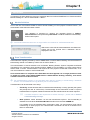
The documentation may be accessed via the top of the main product window, via the Project tab or
via the context sensitive F1 key.
The Documentation is presented via a Help Viewer, which comprises an Explorer style Contents list complete
with Search function and a reading pane.
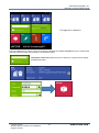
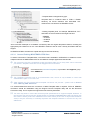
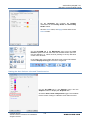
Entering AVEVA Everything3D 2.1
AVEVA Everything3D 2.1 may be accessed via the Windows Start menu or Start screen depending on the
Windows Operating System being used.
AVEVA Plant > Design > Everything3D 2.1.0 from the Windows Start Menu.
Copyright © 2015.
AVEVA Solutions Limited and its subsidiaries.
All rights reserved.
20
www.aveva.com
AVEVA Everything3D™ 2.1
Migration & Interoperability Guide
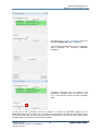
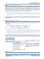
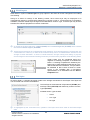
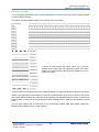
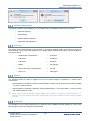
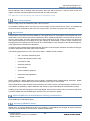
The Login form is displayed.
From the Login form a project may be accessed by selecting the identified Project tile prior to entering the
required login information and clicking on the desired module.
The Project search Tile allows the user to search for a project and to display
masked project tiles.
Copyright © 2015.
AVEVA Solutions Limited and its subsidiaries.
All rights reserved.
21
www.aveva.com
AVEVA Everything3D™ 2.1
Migration & Interoperability Guide
This page is intentionally left blank
Copyright © 2015.
AVEVA Solutions Limited and its subsidiaries.
All rights reserved.
22
www.aveva.com
Chapter 3
3 Project Migration
This chapter gives an overview of the process of migrating from AVEVA PDMS and AVEVA Hull &
Outfitting to the new AVEVA E3D 2.1 product.
The process is slightly different if the two products are used in conjunction on a project; in this case, it is
important that a recent version (and Fix release) of AVEVA PDMS or Hull & Outfitting is used. AVEVA E3D
databases are compatible with PDMS but a number of the enhancements in AVEVA E3D require a minor
upgrade to the database schema; this means that PDMS must be at version 12.1.SP4 Fix.28 or later.
It is recommended that a project backup is created prior to starting any migration process.
Migrating projects from AVEVA PDMS or Hull & Outfitting 12.0
The following guidance is for those customers who currently utilise PDMS or Hull & Outfitting 12.0 on a
Project, this section can be omitted where a Project uses AVEVA PDMS or AVEVA Hull & Outfitting 12.1.
For those customers using AVEVA PDMS 11.6, please refer to the User Bulletin for PDMS 12.0 for
full details on the migration process to AVEVA PDMS 12.0.
Both AVEVA PDMS 12.0 and 12.1 brought significant changes to the database, which need to be applied
prior to the migration to AVEVA E3D 2.1.
The procedure for Global projects is more complex; please refer to the PDMS and Global User
Bulletins. It may be advisable to consider consolidating a project at the hub and redistributing it when
the upgrade is complete.
AVEVA PDMS 12.0 AVEVA PDMS 12.1
Key developments at AVEVA PDMS 12.1 include Unicode handling, revised UKEYs and Draft Line Widths.
The upgrade process is summarised by:
Install PDMS 12.1.SP4 Fix Release 28 and use the command syntax: DBupgrade project
to latest.
Is should be noted that once upgraded the Project data cannot be accessed via earlier versions of
AVEVA PDMS.
Please refer to the User Bulletin for PDMS 12.1.SP4 for full details and is further described in this
guide in Appendix A: Migration from PDMS 12.0 to 12.1.
Customers’ own PML applications may need adjustment for changes in AVEVA PDMS and Hull &
Outfitting 12.1. Please refer to the relevant User Bulletins for further details.
AVEVA Hull & Outfitting 12.0 AVEVA Hull & Outfitting 12.1
Further to above there was an optional database upgrade (no 12010301) between AVEVA Hull & Outfitting
12.1.SP2 and 12.1.SP3. This should be considered as the upgrade item 2931 Storing of coordinate
system entities under a GENPRI element is relevant to AVEVA E3D 2.1 where there is a wish to make
use of this feature.
Please refer to the AVEVA Hull & Outfitting 12.1.SP3 User Bulletin – Chapter 2 Upgrading from
Previous Release for further information.
Copyright © 2015.
AVEVA Solutions Limited and its subsidiaries.
All rights reserved.
23
www.aveva.com
AVEVA Everything3D™ 2.1
Migration & Interoperability Guide
Preparing an AVEVA PDMS or Hull & Outfitting 12.1.SP4 Project
There are no major database changes between PDMS 12.1 and AVEVA E3D 2.1. However, if PDMS 12.1
is to be used on the same project as AVEVA E3D, it is important that PDMS 12.1.SP4 (Fix 28 or later) is
used.
Chapter 6 Compatibility & Interoperability outlines the use AVEVA E3D 2.1 alongside AVEVA
PDMS or AVEVA Hull & Outfitting 12.1.SP4.
A project that uses only AVEVA PDMS or AVEVA Hull & Outfitting 12.1 and/or AVEVA E3D has no need
for legacy text formats so all databases could be migrated to the current Unicode database format.
However, this is not mandatory.
The encoding of a database can be checked using the command Q DBTEncoding.
It is of course necessary to ensure that the AVEVA E3D environment variables are set up to access the
PDMS project; this can be achieved by adding a call to the project in custom_evars.bat.
In order to secure legacy data, projects may continue to reference 12.0 databases (in read mode) as foreign
databases. However, customers are recommended to validate this in their domain as AVEVA is unable to
replicate the wide variety of customer data configurations.
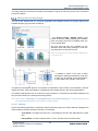
Marine Projects (Hull data) in AVEVA E3D 2.1
When using AVEVA E3D 2.1 in a marine context there are two alternatives for the project environment.
AVEVA E3D 2.1 can be started with either:
A project marked as ‘Plant’ with Hull 12.1.SP4 databases included as foreign databases.
The Hull databases are read-only in this alternative, providing a visual Hull context for the modelling
of Outfitting elements.
In this scenario hull settings must be made available to AVEVA E3D 2.1. This is achieved via a
function in the Inithull utility found in AVEVA Hull & Outfitting 12.1.SP4 Fix 23 onwards. The function
transfers the Hull System Defaults to the Hull database.
Drawing databases should not be included as foreign databases. Drawings stored in a 12.1
format will be transformed when opened in AVEVA E3D 2.1 Draw and this requires write access
to the PADD database.
A project marked as ‘Marine’.
This is a full marine environment, including the project setup d065 file and a number of default files
controlling settings for Hull modelling and drafting.
A marine project environment, including these settings, is required for the marine specific AVEVA
E3D 2.1 Draw functionality such as the creation and modification of Hull Symbolic Views.
Please note that spaces in their pathnames should be avoided for AVEVA Marine (Hull) 12.1.SP4
projects.
Preparing an AVEVA Everything3D 1.1 project
An AVEVA E3D 1.1 project may be used with AVEVA E3D 2.1 without any project migration or restriction.
It should be noted that the use of AVEVA E3D 1.1 and AVEVA E3D 2.1 on the same project is not a
supported setup.
Please refer to Chapter 4 Model Data for further information on the migration of Model data to support
the new Model functionality found in AVEVA E3D 2.1.
Copyright © 2015.
AVEVA Solutions Limited and its subsidiaries.
All rights reserved.
24
www.aveva.com
AVEVA Everything3D™ 2.1
Migration & Interoperability Guide
AVEVA Catalogue and AVEVA Administration
AVEVA E3D 2.1 is released alongside and supported by AVEVA Catalogue 2.1 and AVEVA Administration
1.4.
In a project scenario where AVEVA E3D 2.1 is used in conjunction with AVEVA PDMS 12.1.SP4 for
example, it is strongly recommended (and is mandatory for some operations) that the latest AVEVA
Administration and AVEVA Catalogue products are used rather than the (PDMS) versions of those
modules.
In regards to the migration process, the use of AVEVA Administration 1.4.0 on an AVEVA PDMS or Hull &
Outfitting 12.1.SP4 project will automatically define the necessary Module Definition for the E3D Draw
module. A user will be unable to access the Draw module until this administrative action has been
completed.
The use of AVEVA Catalogue 2.1 is essential in supporting the migration process of PDMS and Outfitting
model data to AVEVA E3D 2.1.
For further information regarding the use of AVEVA Catalogue 2.1 in supporting model data migration
please refer to Chapter 4 Model Data.
Customer PML & .NET Applications
Before considering the migration of any customisations to AVEVA E3D 2.1 it is important to assess the
extensive functionality and redefined workflows found therein. After consideration, it may be found that
previous customisations have been rendered redundant or require adapting to ensure the most efficient
workflow is promoted.
The majority of customisations should operate as expected in AVEVA E3D 2.1 but may require adjustment
where the customisation is called from, or accessed via, a menu bar or toolbar as these do not exist in the
Model or Draw modules. Further, aspects of AVEVA E3D Draw that differ somewhat from PDMS Draft and
Marine Drafting will necessitate changes to customisations.
For more details, please see Chapter 7 Customisations.
As Draw is a new module at AVEVA E3D, any changes made to the module definition for PDMS Draft may
also be required for Draw.
It should be noted that Users can no longer define new modules in AVEVA Administration.
As module switching between AVEVA Administration or Catalogue modules and AVEVA E3D modules
is no longer possible, any macro doing this will need to be re-structured. In addition, some forms may
need adjustment to their layout for best presentation.
Copyright © 2015.
AVEVA Solutions Limited and its subsidiaries.
All rights reserved.
25
www.aveva.com
AVEVA Everything3D™ 2.1
Migration & Interoperability Guide
This page is intentionally left blank
Copyright © 2015.
AVEVA Solutions Limited and its subsidiaries.
All rights reserved.
26
www.aveva.com
Chapter 4
4 Model Data
The following chapter outlines the key migration considerations where model data from an AVEVA PDMS
or AVEVA Marine 12.1.SP4 project is to be used with AVEVA E3D 2.1.
Structural
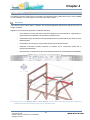
A key feature of the AVEVA E3D 2.1 product, the structural application places the model at the centre of
design workflows.
Highlights of the structural application include the following:
Less reliance on forms and menus with direct graphic input and interaction; supported by a
gesture based PowerWheel™ and powerful Properties Grid.
Automated storage of elements and a grid allied structural model reduces the reliance on the
Model Explorer.
Preservation of user input to ensure data persists and is easily retrieved.
Automatic connection between elements at creation and a connectivity model that is
dynamically maintained.
New and more comprehensive Structural Catalogues based on the latest National Standards.
Please refer to the AVEVA E3D 2.1 User Bulletin for an outline of the key structural concepts and
available structural functionality in the E3D 2.1 Model module.
Copyright © 2015.
AVEVA Solutions Limited and its subsidiaries.
All rights reserved.
27
www.aveva.com
AVEVA Everything3D™ 2.1
Migration & Interoperability Guide
Section Conversion
To enable the use of the AVEVA E3D 2.1 structural application functionality to modify existing model data,
it is necessary to convert all Section (SCTN) elements to GENSEC elements.
It is recommended that this action is the first step taken in the conversion process for a structural model
and that the process is completed in manageable hierarchy segments i.e. STRUs or FRMWs depending
on the complexity of the model.
It is recommended that where the conversion of MDS Template data is required, the SCTN to
GENSEC conversion process should be undertaken using the Support Convert Template utility and
not the Structural Conversion utility. Please refer to Section 4.3.3 Template Data.
As part of the conversion process:
Fitting (FITT) and Joint (SJOI) elements are converted to Fitting (FIXING) and Joint (FIXING)
elements.
Primary Node (PNODE) and Primary Joint (PJOI) elements are converted to End Datum
(ENDATU) elements that own a Joint (FIXING) with the referenced joint.
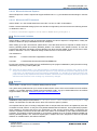
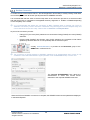
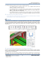
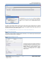
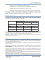
A utility, Convert Sections, is provided in the Structures group of the
ADMIN tab in AVEVA E3D 2.1.
The conversion of SCTN elements to GENSEC elements is an administration task; access is only
available to users with administration rights (member of the STRUADMIN team) or a free user.
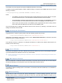
The Convert SCTN/GENSEC form allows the
Administrator to select and convert SCTN
elements to the required GENSEC elements.
When the SCTN to GENSEC conversion is complete, the GENSEC elements are updated and displayed
in the Model Explorer.
Copyright © 2015.
AVEVA Solutions Limited and its subsidiaries.
All rights reserved.
28
www.aveva.com
AVEVA Everything3D™ 2.1
Migration & Interoperability Guide
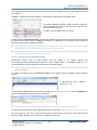
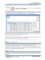
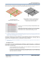
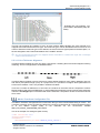
The Model Explorer highlights the result of the conversion process:
The utility converts SCTN elements to straight GENSECs i.e. the
GENSEC’s SPINE (only) owns two POINSP elements.
Any connections, i.e. SNOD/SJOI elements, are converted to the
equivalent GENSEC elements of JLDATU/PLDATU/FIXING, and all
connectivity remains, as are all joints and fitting Specification References.
PNOD/PJOI elements, say for baseplate joints on the bottom of columns,
are converted to the new ENDATU element and the SpecRef maintained.
The utility presents a conversion summary and
maintains a log file to which any errors in the
conversion process are written.
Catalogue – Joints & Fittings
A new profile catalogue, based on the latest National standards, has been developed for AVEVA Catalogue
2.1. Translation of Joints and Fittings is required to ensure compatibility with the P-line and Profile
parameter of the new profile catalogue.
Where joint and fitting catalogues are to be translated, this should be done prior to updating the
Specification Reference of existing GENSECs to use the new catalogue profiles. This is due to the Profile
Catalogue update referring to the updated Joints & Fittings in the update process.
Please refer to the AVEVA E3D 2.1 User Bulletin for an outline of the key changes to the structural
catalogue at AVEVA Catalogue 2.1.
It is not necessary to update to the new catalogue as AVEVA E3D 2.1 will function correctly with the
‘old’ catalogue data, however, images on the joint and fitting selection forms will not be available.
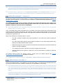
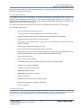
A utility is provided in AVEVA Catalogue 2.1 to translate joint and fitting catalogues,
and specifications that work with the previous catalogue to work with the new
catalogue.
The utility, Translate Joints/Fittings Catalogue in the
Tools group of the SPECIFICATION tab in Paragon, copies
the former specifications and then interrogates the reference
data to translate it to the ‘new’ catalogue
The Translate Joints and Fittings Specifications form is displayed, as shown on the following page, and
allows the selection of the Specification World (SPWL) or Specification (SPEC) to be validated and
translated.
Copyright © 2015.
AVEVA Solutions Limited and its subsidiaries.
All rights reserved.
29
www.aveva.com
AVEVA Everything3D™ 2.1
Migration & Interoperability Guide
It is important to consider that if the catalogue joints or fittings do not comply with the way the AVEVA
sample joints and fittings in the ‘old’ catalogue are constructed, or the parameter order/Dkey attributes of
the profiles that they relate to have been changed, then the translation process will be unsuccessful and
the translation must be done manually.
It should also be noted that template joints and fittings cannot be translated automatically. They must
be translated manually.
Catalogue – Profiles
As indicated in the previous section, a new profile catalogue has been introduced alongside the AVEVA
E3D 2.1 structural capability. The new profiles have common Gtype geometry and P-line sets, together with
a common data set. Therefore joints and fittings, developed for and used with the previous profile catalogue
(AVEVA PDMS and Hull & Outfitting 12.1.SP4 / AVEVA E3D 1.1) will not work with the new catalogue at
AVEVA E3D 2.1.
In addition, Angle profiles have been re-orientated to conform to National Standards and to be aligned with
the typical orientation used by other software packages.
The profile specification of GENSEC and FIXING elements must be converted for compatibility with the
most recent profile specification catalogue.
It is not necessary to update to the new catalogue as AVEVA E3D2.1 will function correctly with the
‘old’ catalogue data, however, images on the joint and fitting selection forms will not be available.
SCTN, FITT and SJOI elements must be converted to GENSEC and FIXING elements prior to
conversion of the profile specification. Joints and fittings applied to GENSECs where the SpecRef is
from the previous catalogue will not work with the new catalogue due to the change in profile parameter
order and the Dkey attributes.
A utility, Update Profile, is provided in the Structures group of the ADMIN
tab. The utility updates profiles from the catalogue previously used to the
new catalogue.
The profile specification conversion of GENSEC and FIXING elements is an administration task,
access is only available to users with administration rights (member of the STRUADMIN team) or a
free user.
Copyright © 2015.
AVEVA Solutions Limited and its subsidiaries.
All rights reserved.
30
www.aveva.com
AVEVA Everything3D™ 2.1
Migration & Interoperability Guide
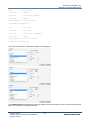
The Convert Profile Sprefs form allows the
Administrator to convert the profile specification of
GENSEC and FIXING elements.
When the conversion is complete, the Attempted and
Succeeded columns are populated with the number of
profile specifications that were attempted for
conversion and the number that were successfully
converted.
The conversion utilises a mapping file, %AVEVA_DESIGN_DFLTS%\profilelist.pmldat, to convert the
Specification references, Gtypes, justification lines, etc.
The Browse… button adjacent to the Mapping File
text box allows the Administrator to navigate to a
required location and select an alternative mapping
file.
It should be noted that whilst the new catalogue contains many more profiles compared to the old catalogue,
for some profiles in the old catalogue there are no equivalent profiles in the new catalogue. This is because
the National Standards have been updated and the profiles have been deleted from the standards.
Similarly, customer profile catalogues or profiles where the Spref name has been changed will not be
updated by this utility unless the mapping file is updated manually.
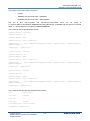
The example below is an extract of a mapping file that indicates the old and new profile specifications.
# File to define profile translation
# to new AVEVA structural catalogue
# <old spco> <new spco>
/AISC/C15x50 /US-C15x50
/AISC/C15x40 /US-C15x40
/AISC/C15x33.9 /US-C15x33.9
/AISC/C12x30 /US-C12x30
/AISC/C12x25 /US-C12x25
/AISC/C12x20.7 /US-C12x20.7
On clicking Apply to convert the profile specifications, a Confirm
message is displayed.
The message informs the Administrator that the catalogue
specifications must be translated before the conversion of the profile
specifications.
It should be noted that Angle profiles are automatically re-orientated to the new catalogue orientation during
the process.
Copyright © 2015.
AVEVA Solutions Limited and its subsidiaries.
All rights reserved.
31
www.aveva.com
AVEVA Everything3D™ 2.1
Migration & Interoperability Guide
The utility presents a conversion summary and maintains a log file to which any errors in the conversion
process are written.
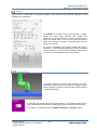
Adding Joint & Fitting Images
The use of the AVEVA E3D 2.1 structural application and workflows therein are greatly aided by the
available images (.png) for joints and fittings.
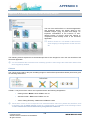
: The Section Fitting / Modify Joints forms
include a selection gallery displaying all available
joints and fixings that may be applied within the
current specification.
All icons and help files are available for the
standard Joints and Fittings catalogue. These are
.png files which are stored in the file:
Aveva.Interaction.Structural.Resource
s.resources.
: In addition a sketch of the joint or fitting
including the defining Parameters of the joint
or fitting can be opened via the Detail button
on the Create Fixing / Modify Joints forms.
In regards to the migration process, an important consideration is the inclusion of user-defined, customer
images of Project Joints and Fittings to complement those already found in the structural application.
The following will describe how to create icons (.png format) for a customer joint and fitting catalogue and
the process to follow in the naming and storing of them.
Please refer to Appendix C. Forming Structural Joint & Fixing Images for further information and
a recommended workflow for the creation of quality images.
4.1.4.1 Naming
All joint and fitting specification components (SPCO elements) within the AVEVA Sample Catalogue are
named following a simple naming convention. For example:
Joint SPCO: J1S1-WEL-PFC-PFC-001, J1S2-SNS-PFI-PFI-001 and J2S4-FEP-PFI-CTUB002.
Fitting SPCO: F1-CIR-CTUB-4H-STIFF, F3-PLT-PFI-001 and F2-FLS-PFI-VAR.
Copyright © 2015.
AVEVA Solutions Limited and its subsidiaries.
All rights reserved.
32
www.aveva.com
AVEVA Everything3D™ 2.1
Migration & Interoperability Guide
The reciprocal image must be named as per the SPCO with the exception that any forward slash is replaced
by a hyphen.
In addition, SELE elements also require an image with a similar naming convention used.
In AVEVA Catalogue Paragon, SPCO and SELE elements
have an attribute Icon which is the full name of the icon file
stored in the resource file.
The ‘ID_’ prefix is added to all icon names.
In determining the help sketch image, the file name is based upon the name of the STCA element (owning
the Catref of the SPCO) where a Catalogue joint/fitting or, alternatively, the Template name (Tmpref of
SPCO) is used where a Template joint/fitting.
The image names are case sensitive so it is advised to use only upper case in icon names. Indeed,
when files are added to resource files the names are all upper case.
When adding .pngs files to a resources file with the Resource Editor the prefix is added automatically
so the prefix is not required on the png file itself.
4.1.4.2 Storage of User-defined Images
Customised images (icons or help sketch) may be added to the default resource file
Aveva.Interaction.Structural.Resources.resources in the AVEVA E3D 2.1 installation folder but it is
recommended to create a new Resource file to store customer images.
Please note that the Joint/Fitting forms must be prompted in AVEVA E3D 2.1 to first populate the
Resource Editor.
To create a new Resource file, the Resource Editor can be utilised from the installation folder of AVEVA
E3D 2.1.
A new Resource File is added on
clicking the + icon.
A new image is added to the resource file by clicking the Add New Resource File from the Bitmaps tab
and then selecting the required .png file to be added.
A png file can also be added to the Resource Editor window by a Drag and Drop action.
The file is to be saved with an easily identifiable name, for example: Company.Resources.resources.
The next step is to open the Aveva.Interaction.Structural.Resources.resources file and edit the string
ID_FILE_STRU_IMAGE_FILE to refer to the created resources file.
Copyright © 2015.
AVEVA Solutions Limited and its subsidiaries.
All rights reserved.
33
www.aveva.com
AVEVA Everything3D™ 2.1
Migration & Interoperability Guide
This reference operation must be done for each installation of the application.
On opening the Joints or Fitting forms, the application will first look within the Company.Resources file
and if no image is found, will proceed to look in the default AVEVA Resource file.
If no image is found in a resource file a default image will be displayed (blank image).
Stairs, Ladders & Handrails
It should be noted that there is no utility provided to update SLH Defaults or Assemblies to use the new
structural catalogue due to the complex cross referencing of elements.
Therefore, it is recommended that if it is desired to use the new profile catalogue with SLH, new Defaults
and Assemblies should be created. It is possible to manually modify Defaults and Assemblies but this
should be approached with caution and contact with AVEVA Support made to go through the process.
Specifications associated with the old AVEVA Catalogue have been disabled. If the old AVEVA
Catalogue is to be used for new SLH elements, the relevant Specification will be required to be
reactivated by setting the PURP attribute for the SPEC to STL. This will display the identified Profiles
in the appropriate SLH forms.
Copyright © 2015.
AVEVA Solutions Limited and its subsidiaries.
All rights reserved.
34
www.aveva.com
AVEVA Everything3D™ 2.1
Migration & Interoperability Guide
Grids
A principal aid to the AVEVA E3D 2.1 Model Designer is the provision of new Grid elements called
Reference Grids. Reference Grids are formed in the Model Database, may be used across an entire project
and added, with automated annotation, to project drawings in AVEVA E3D 2.1 Draw.
: Clipped Model Graphic along a Grid Plane
with Model annotation (Elevations and Grid
Labels).
:Isometric view of Grid (with associated Structure) in
Draw with automated annotation (Elevations and
Grid Labels).
Please refer to the AVEVA E3D 2.1 User Bulletin for an outline of available Grid functionality and
how they may be utlilised and incorporated into both Draw and Model alike.
Ship & Plant Grid Conversion
To facilitate use across a project, Plant and Ship Grids are stored in a Design (DESI) database. In AVEVA
PDMS and Hull & Outfitting 12.1.SP4 and AVEVA E3D 1.1 the Grid is stored beneath a Grid System
(GRDSYS) element, while in AVEVA E3D 2.1 the Grid is stored below a Reference Grid (REFGRD).
A conversion tool is available in AVEVA E3D 2.1 Model to convert Grids from GRDSYS to REFGRD
elements.
Copyright © 2015.
AVEVA Solutions Limited and its subsidiaries.
All rights reserved.
35
www.aveva.com
AVEVA Everything3D™ 2.1
Migration & Interoperability Guide
The conversion is considered an administrative task and is
available via the Convert Grid System button in the Grids
group of the ADMIN tab.
The Convert Grid System process is an administrative task; access is only available to users with
administration rights or as a free user.
The Convert GRIDSY/REFGRD form
allows the Administrator to select
GRIDSY elements for conversion by
defining all elements, selected elements
or named elements within the project.
The utility presents a conversion
summary and maintains a log file to which
any errors in the conversion process are
written.
When the GRIDSY to REFGRD conversion is complete, the REFGRD
elements are displayed in the Model Explorer.
All Grid Axis (GRIDAX) and Grid Line (GRIDLN) elements are converted to
Grid Face (GRIDFA), Grid Elevation (GRIDEL) and Grid Plane (GRIDPL)
elements.
The original GRIDSY elements are not deleted as part of the conversion and can be deleted manually.
For Hull users, please note that Hull Grid Elements (GENTAB) are not visible in the Model Hierarchy;
having been converted to GRIDSYS elements in AVEVA Hull & Outfitting 12.1.SP4.
The following naming rules apply to the conversion of GRIDSY elements:
If the original GRIDSY element is named, the suffix ‘_REF’ is added to the name of the new
REFGRD element.
If the GRIDSY element is not named and the Purpose property is SHIP, the new REFGRD
element is named ‘SHIP_GRID_REF’.
If the GRIDSY element is not named and the Purpose property is set to be other than SHIP,
the REFGRD element is not named.
Copyright © 2015.
AVEVA Solutions Limited and its subsidiaries.
All rights reserved.
36
www.aveva.com
AVEVA Everything3D™ 2.1
Migration & Interoperability Guide
The following naming rules apply to the conversion of GRIDAX elements:
If the GRIDAX element is named, the suffix ‘_FA’ or ‘_EL’ is added to name of the new
GRIDFA and GRIDEL elements respectively.
If the GRIDAX element is not named and the Purpose property of the owning GRIDSY
element is SHIP, the new GRIDFA and GRIDEL elements are named ‘SHIP_X_FA’,
‘SHIP_Y_FA’ and ‘SHIP_Z_EL’ respectively.
If the GRIDAX element is not named and the Purpose property of the owning GRIDSY
element is set to be other than SHIP, the new GRIDFA and GRIDEL elements are not named.
Auto naming rules can be applied to Grid Planes.
An auto naming file providing Grid Plane names for the Ship Grid, in the same format as in AVEVA
Hull & Outfitting 12.1SP4, is installed with AVEVA E3D 2.1.
Supports
A key development in AVEVA E3D 2.1, the Supports application enables users to create multi-discipline
supports using an efficient and intuitive workflow that does not require write access to Piping, Cable, HVAC
or connecting Steelwork elements. Extending existing configuration capabilities, AVEVA E3D 2.1 allows
the user to configure various support types available within the Supports application to meet project
requirements.
Please note that AVEVA Outfitting Supports is not available in AVEVA E3D 2.1.
In order to use the new Supports application with AVEVA PDMS or Hull & Outfitting 12.1.SP4 or AVEVA
E3D 1.1 version model data, a number of conversion steps are necessary to make existing model data
compatible with the new application.
Before project data can be successfully upgraded to function within the AVEVA E3D 2.1 environment the
Administrator must ensure that all product updates have been performed to align it with the update
Copyright © 2015.
AVEVA Solutions Limited and its subsidiaries.
All rights reserved.
37
www.aveva.com
AVEVA Everything3D™ 2.1
Migration & Interoperability Guide
requirements for AVEVA E3D 2.1. The conversion process requires that the customer project utilises either
AVEVA PDMS or Hull & Outfitting12.1.SP4 Fix.28 (earliest compatible fix with AVEVA E3D 2.1) or AVEVA
E3D 1.1.
Database Updates
In using the Supports application at AVEVA E3D 2.1 it is important to consider that many of the default
AVEVA maintained database libraries used previously have been updated for AVEVA E3D 2.1 and will
need to be included or replaced within customer projects.
The databases used by the MDS application are split into two classes
AVEVA controlled reference libraries i.e. those databases that are maintained by AVEVA and
generally regarded as being non-user definable.
User definable template and configuration databases i.e. those databases that contain
client/project specific customised supports data.
AVEVA controlled reference library updates:
The following library databases are required by the new Supports application and the existing user
references to these items must be reset to the AVEVA ACP project versions:
MDS/CATA
DB 7320
MASTER/MDSDICT
DB 7325
User definable template & configuration databases
These are user defined database items that may already exist within customer versions of AVEVA PDMS
or Hull & Outfitting 12.1.SP4 or AVEVA E3D 1.1. For example:
MDS/APPDEFAULTS
MDS/DESITMPL-BS
MDS/DESITMPL-BS-ORI
MDS/DESI-SPECIAL-TMPL-BS
MDS/DESITMPL-PSL
In such cases were existing user/corporate versions of these databases exist then such databases can
either be included within the working project by either foreign reference or by a direct copy into the working
project.
Further information regarding project setup is located in the Supports Customization guide.
The following is an example administrative workflow to replace the MAS Project reference library data with
the ACP Project library data within a working project. User defined template databases are included via
foreign data reference but they could also be copied into a working project as previously stated.
Copyright © 2015.
AVEVA Solutions Limited and its subsidiaries.
All rights reserved.
38
www.aveva.com
AVEVA Everything3D™ 2.1
Migration & Interoperability Guide
It is recommended that where user maintained data is to be updated to work in the AVEVA E3D 2.1
environment, backup copies of the project or relevant databases are taken before work commences.
1. Exclude MAS Reference Databases.
2. Include required ACP Reference Databases.
3. Include required Support Template Databases.
If the project to be updated for use in AVEVA E3D 2.1 already includes the MDS template
databases etc. listed below then it is unlikely that further steps are required in the administration
before moving on to the next update step. The following steps are therefore included for reference:
For new projects Support template databases are (normally) copied to a user project to enable
editing. The sample versions of these databases are supplied in the APS project. In the case
below we consider the situation where customer versions of these databases already exist in
PDMS or E3D1.1 and need to be included within the working project that is being converted for
use in E3D2.1. In the example below we assume that customer template database data is stored
within a corporate reference project named COR and the required data will be included in the
working project by a foreign reference.
Databases required by the Supports Application:
MDS/WELDS
MDS/DRAFT
MDU/CATA
MDS/APPDEFAULTS
Framework Template Data – one or more databases are required from the following list:
MDS/DESITMPL-AISC
MDS/DESITMPL-BS
MDS/DESITMPL-DIN
MDS/DESITMPL-OGLAEND
Note: Additionally, if defined, the following databases can also be included but only if the non-ori version is also included
MDS/DESITMPL-AISC-ORI
MDS/DESITMPL-BS-ORI
MDS/DESITMPL-DIN-ORI
Special Template Data – one or more databases are required from the following list:
MDS/DESI-SPECIAL-AISC
MDS/DESI-SPECIAL -BS
MDS/DESI-SPECIAL -DIN
Hanger Template Data – One or more databases are required from the following list:
MDS/DESITMPL-GRI
MDS/DESITMPL-PIHASA
MDS/DESITMPL-PSL
4. Add the New Steelwork Reference Databases.
MASTER/STL_PROFILE_CATA
MASTER/STL_PROFILE_SPECS
MASTER/STL_JOINTS_FITTS
MASTER/STL_JOINTS_FITTS_TMPL
5. Update all MDBs to re-add the included / new databases.
Where user modified databases are being included within the AVEVA E3D 2.1 environment, additional
update steps may be required for use in the supports application. These are detailed in subsequent
sections
Copyright © 2015.
AVEVA Solutions Limited and its subsidiaries.
All rights reserved.
39
www.aveva.com
AVEVA Everything3D™ 2.1
Migration & Interoperability Guide
Supports Application Defaults
The new Supports application uses an application defaults database (MDS/APPDEFAULTS) to store user
customisable design data in the same way that the previous MDS application did within AVEVA PDMS 12.1
SP4 and AVEVA E3D 1.1.
Several updates have been made to the structure of the MDS/APPDEFAULTS database at E3D2.1 which
means that user maintained versions of this database will need to be upgraded to the new version before
use.
The provided upgrade tool allows the user to easily update existing standards or add application defaults
for any new standards that have become available. The tool is relevant where upgrading from a previous
version of a project or continuing work on a project that uses a previous version of the MDS/APPDEFAULTS
database.
The utility to check and update the Supports Application Defaults is provided in the
AVEVA Catalogue 2.1 Paragon module.
The tool is accessed by clicking the Check Supports Application
Defaults button in the Tools group of the Supports tab.
The user must have suitable permissions to modify the catalogue to successfully update the Supports
Application Defaults.
The Check Supports Application Defaults form is prompted.
The Check Defaults button allows the user to check the Supports application
defaults database against the standard set of defaults contained in the MDS
project.
Copyright © 2015.
AVEVA Solutions Limited and its subsidiaries.
All rights reserved.
40
www.aveva.com
AVEVA Everything3D™ 2.1
Migration & Interoperability Guide
The defaults database is checked to determine if any default standards are missing or if any updates to
existing standards need to be applied.
The Check and subsequent update may take a prolonged period of time to complete.
All detected updates to existing standards or missing default standards are identified in the Check
Supports Application Defaults form.
The Update Defaults button is clicked to add or update an application
default within the project defaults database. Once completed, a Message
window is displayed to inform the user that the required number of
defaults have been successfully created or updated.
A log file containing detailed information about the modifications to the database is created during the
defaults update. The log file is created in the current %AVEVA_DESIGN_USER% directory and is named
mdsDefaultsUpdate.log.
Template Data
MDS/TEMPLATES based template data from AVEVA PDMS 12.1.SP4 and AVEVA E3D 1.1 is no longer
compatible for use with the Supports application at AVEVA E3D 2.1. A conversion tool is provided to
transfer existing template data into a recognised format.
Three main changes have been implemented to the format of template data for use with the Supports
application.
Template data is now stored in an application data world hierarchy rather than a site based
hierarchy.
All SCTN members and sub-members have been converted into GENSEC based hierarchies.
All PNOD / PJOI constructs are converted to ENDATU / FIXING constructs that are owned
by GENSECs.
: The application data world hierarchy separates the template
data from the 3D model in the sense that it no longer belongs
to a Site.
By default, application data world elements are not visible to the user in the Model Explorer as they
are considered to be administrative elements.
Copyright © 2015.
AVEVA Solutions Limited and its subsidiaries.
All rights reserved.
41
www.aveva.com
AVEVA Everything3D™ 2.1
Migration & Interoperability Guide
: Template data is categorised by type.
Template data is contained within a STRU / FRMW
hierarchy. All SCTN elements and associated submembers are converted to the GENSEC format.
: Existing template joints, for example, SNOD/SJOI, FITT
and CMFI are all converted to the single format of:
GENSEC
> JLDATU
> PLDATU
> FIXING
Joint conversion attempts to re-establish connectivity with the original template members, including the
appropriate joint references on the new GENSEC members and all rules currently associated with the
support.
All SUBS and TMPL elements are copied directly into the new hierarchy.
4.3.3.1 Convert Existing MDS/TEMPLATES Sites
To aid the conversion of Template Data, a conversion tool is available in AVEVA E3D 2.1 Model to convert
multiple instances of MDS/TEMPLATES in one MDB into multiple Application Data Worlds.
The conversion process is undertaken at site level where either one or many sites can be converted
per session. Template conversion can be staggered across sessions.
A conversion tool, Convert Templates, is provided in the Supports group
of the ADMIN tab.
The Template conversion task is an administration task; access is only available to users with
administration rights or as a free user.
UDA updates may be required before template conversion can proceed – please refer to Section
4.3.3.3 Missing UDA Definitions.
It is recommended that where the conversion of MDS Template data is required, SCTN to GENSEC
conversion should be undertaken using the Support Convert Template utility and not the Structural
Conversion utility. This is required to support the new hierarchy described.
The User may wish to convert the structural profile specifications for support template steelwork. In
this case the user should use the “Update Profile” tool detailed in Sections 4.1.2 & 4.1.3. Please note
that cases in which profile size substitutions have been made (in the case of deprecated steelwork
sizes) it may be necessary to manually reposition the template steelwork to account for any size
differences.
Copyright © 2015.
AVEVA Solutions Limited and its subsidiaries.
All rights reserved.
42
www.aveva.com
AVEVA Everything3D™ 2.1
Migration & Interoperability Guide
On clicking the Convert Templates button the
Convert Template Site form is displayed.
The potential Template Sites to be converted are
listed alongside the respective Database
Names(s).
Candidate templates may be promoted and
demoted for conversion by the use of the up and
down arrow buttons below the listed Template
Sites.
At the end of the conversion process a number of checks are performed against the old
MDS/TEMPLATES site to identify any conversion errors that have occurred that may require review.
Errors occur when rules are re-executed and cannot be evaluated or when the geometry of the support
template does not match that of the previous template.
Copyright © 2015.
AVEVA Solutions Limited and its subsidiaries.
All rights reserved.
43
www.aveva.com
AVEVA Everything3D™ 2.1
Migration & Interoperability Guide
Conversion status, including possible conversion
errors, is highlighted by the Conversion status area
of the form.
Templates with possible conversion errors can be
selected and investigated via the Details button.
The Template Conversion Details form is prompted and displays possible errors detected: Rule Definition,
Joint Definition or Geometry Definition errors.
Upon selection of an Error, the details of the error display in the Error Details section of the form and the
appropriate elements from the new Application Data World are added to the 3D View Drawlist.
In the example below, a Rule that cannot be evaluated is elaborated upon by the provision of the Rule
definition.
When the site conversion is complete, the new Application Data World is available for use. The naming of
the APPLDW is taken from the Database name.
For example, MDS/TEMPLATES in the Database MDS/DESITMPL-BS is converted to
APPLDW/SUPPORT/FRAMES/BS. If no suffix is found, the APPLDW uses a number as the suffix. For
example SUPPORT/FRAMES/1.
The database session must be saved to ensure that the converted Application Data World is stored.
It is recommended that the converted data is reviewed following conversion. If conversion errors are not
encountered, the original /MDS/TEMPLATES site can be deleted from the database.
It is recommended that the user creates a database listing of each /MDS/TEMPLATES site before
deletion to allow for ease of restoration.
Copyright © 2015.
AVEVA Solutions Limited and its subsidiaries.
All rights reserved.
44
www.aveva.com
AVEVA Everything3D™ 2.1
Migration & Interoperability Guide
4.3.3.2 Template Sets
Different sets of templates, individually contained in APPLDW elements, can exist in the same MDB. For
example an APPLDW may contain BS, DIN and AISC framework template sets.
Each APPLDW must have a Purpose attribute (PURP) set. By default, the correct Purpose is automatically
assigned during the conversion process. Each template type is based on the Purpose of the APPLDW:
Framework templates: Purpose = MDST.
Special templates: Purpose = MDSS.
Hanger templates: Purpose = MDSH.
ORI framework templates: Purpose = MDSO.
The Description (DESC) of the APPLDW is taken from the description of the converted SITE. For example:
SUPPORT/FRAMES/BS
SUPPORT/FRAMES/DIN
SUPPORT/FRAMES/AISC
The Supports application defaults may be interrogated at any time
via the Defaults option in the Settings group of the SUPPORTS tab.
The prompted Supports Application Defaults window allows an overview of, and the ability to modify, the
Supports application defaults.
The Supports Admin Data form in AVEVA Catalogue 2.1 (accessed via the Application Defaults
button in the Configuration group of the SUPPORTS tab) modifies values in the file
Copyright © 2015.
AVEVA Solutions Limited and its subsidiaries.
All rights reserved.
45
www.aveva.com
AVEVA Everything3D™ 2.1
Migration & Interoperability Guide
MDS/OPTION/DEFAULTS – the basis of the defaults set in the Supports Application Defaults form in
the Model module.
The default Support Creation Zone and Templates to be used
in the Support creation workflows are referenced in the identified
area of the form and may be modified via the Select… button.
The prompted Creation Zone and Framework Templates form allows the selection of framework
templates, special templates and hanger templates for the project. ORI framework templates are based on
the selected framework template.
In regards to the setting of the Support Zone default, it is important to note that AVEVA PDMS
Supports and AVEVA E3D 2.1 Supports cannot share the same Zone.
The purpose of the Zone should also be set as defined within the Support Admin Data form in
AVEVA Catalogue 2.1. By default the Zone Purpose is set to SUPP.
Once set, the selection is stored in %AVEVA_DESIGN_DFLTS% and is retained for each user session.
4.3.3.3 Missing UDA Definitions
Prior to Support Template conversion, UDA updates may be required to support the conversion of SCTN
to GENSEC elements.
UDA updates would be required where users have appended their own attributes to SCTNs within a project.
Because we are converting from SCTN to GENSEC we need to ensure that GENSEC elements can store
the same UDA data that a SCTN can otherwise we risk losing user data when performing the conversion.
A Message is prompted on clicking the Convert Templates button
in the Supports group of the ADMIN tab where missing GENSEC
UDA definitions are detected that exist for SCTN elements.
On confirming the message dialog, the SCTN > GENSEC UDA checking tool is displayed with the UDA
and Error Types listed.
Copyright © 2015.
AVEVA Solutions Limited and its subsidiaries.
All rights reserved.
46
www.aveva.com
AVEVA Everything3D™ 2.1
Migration & Interoperability Guide
On clicking the write uda update macro button a message is
prompted to inform the user of the location of the update files
to be run into the Lexicon module of AVEVA Administration
1.4.
4.3.3.4 User Defined Attributes
By default, User Defined Attributes (UDA) that are being used to store supports data (i.e. Supports
application specific UDAs) are no longer visible. To query an application specific UDA, a direct line
command must be used. For example, q :MDSSuppRef. It is possible to query which UDAs exist on an
element by use of the q udaLis line command.
The UDA :MDSPipeMat CS is an exception and is visible within AVEVA E3D 2.1.
Model Data Upgrade
Model data conversion utilities to upgrade existing model data (i.e. ATTA based support elements) will be
provided via an AVEVA E3D 2.1 Fix Release.
Support Designer Access
The hierarchy structure and creation workflows of
the Supports application at AVEVA E3D 2.1 allows
the potential to alter the access permission for a
Support designer to remove access to Pipes,
Steelwork, Tray and HVAC if appropriate. This is
completed via the Modify User forms in AVEVA
Administration.
Copyright © 2015.
AVEVA Solutions Limited and its subsidiaries.
All rights reserved.
47
www.aveva.com
AVEVA Everything3D™ 2.1
Migration & Interoperability Guide
Piping
AVEVA E3D 1.1 introduced an enhanced graphical user interface and functional workflow for Pipe
modelling and modification.
The PIPING tab includes all the tools required to create,
modify and check piping elements. The creation and
modification of piping elements is further supported by a
series of intuitive forms, such as the Piping Component
Editor, that combine a number of modelling tasks into one
logical user interface.
To ensure compatibility with AVEVA PDMS and Hull &
Outfitting 12.1.SP4 the piping application has been extended
at AVEVA E3D 2.1 to account for functionality introduced in
12.1.SP4 e.g. Non-Standard Branch Connections.
Sloping Pipes
The Piping application sloping pipe capability has been
extended at AVEVA E3D 2.1 to allow for multiple sloping
pipes at a piping component (plus the representation thereof
in IsoDraft and Draw).
In regards to the migration process to AVEVA E3D 2.1, an update is required to the
Piping Catalogue(s) to utilise the multiple sloping pipe to component functionality.
The update is completed using the AVEVA Catalogue 2.1 Paragon module.
Copyright © 2015.
AVEVA Solutions Limited and its subsidiaries.
All rights reserved.
48
www.aveva.com
AVEVA Everything3D™ 2.1
Migration & Interoperability Guide
The update involves setting the P-Point offset
tolerance (OFFTOL) on all the P-Points of the
element required to be sloped from/to.
In the example here the OFFTOL is set to 12
degrees to allow for a maximum possible slope
of 1 in 5 (11.7 degrees).
Copyright © 2015.
AVEVA Solutions Limited and its subsidiaries.
All rights reserved.
49
www.aveva.com
AVEVA Everything3D™ 2.1
Migration & Interoperability Guide
Setting the OFFTOL allows the piping user to directly slope away
from the identified P-Point using the Piping user interface.
Piping & Supports
Although not detrimental to the use of the data in AVEVA E3D 2.1, where migrating supports data from
AVEVA PDMS or Hull & Outfitting 12.1.SP4, an Administrator may consider removing the MDS updates
from piping elements Reducers, Tees, and Elbows. This can be considered as the Supports application no
longer requires such modifications for the creation of Trunnions.
Laser
A key facet of the AVEVA E3D 2.1 product is the use of, and interaction with, laser data in the Model and
Draw environments. Key laser features improved upon and introduced in AVEVA E3D 2.1 include:
Integrated Laser User Interface.
Exact Clashing with intuitive object-centric reporting.
Integrated and simplified Pipework Modelling.
Laser data area management & Demolition.
Incorporation of Laser Data in E3D Draw Drawings.
HyperBubble™ technology allowing the user to walk or fly though a combined Model and
BubbleView quality environment.
Copyright © 2015.
AVEVA Solutions Limited and its subsidiaries.
All rights reserved.
50
www.aveva.com
AVEVA Everything3D™ 2.1
Migration & Interoperability Guide
Please refer to the AVEVA E3D 2.1 User Bulletin and User Documentation for further information on
laser capabilities in AVEVA E3D 2.1.
Preparing for the HyperBubble
There is no specific migration process for laser data within a Project but in order to access the HyperBubble
functionality, the laser data must have a texture render applied using LFM Server 4.4.
Please refer to the LFM Server 4.4 user documentation for further information on the rendering process
for laser data.
Compare / Update
Compare / Update has a dedicated tab (and form) accessed via the
For more information on the general functionality of Compare / Update please refer to the
Compare/Update User Documentation.
For further information on new features introduced at AVEVA E3D 2.1, please refer to the AVEVA
E3D User Bulletin.
Configurations from earlier versions of Compare / Update require upgrade at AVEVA E3D 2.1.
A member of team CUADMIN can trigger an automatic upgrade by opening the Options dialogue. If
upgrades are available a prompt will be displayed to proceed. Once completed a log file will be displayed.
This file is stored in the folder CUConfigs2.0 under the project defaults folder. The file will list which
configurations have been upgraded or skipped, along with any warnings.
The upgrade will not overwrite any configurations already defined in the later version. It will first
upgrade available configurations from AVEVA Engineering 14.1 and then from earlier versions of
AVEVA PDMS or Hull & Outfitting 12.1.SP4. Note that configurations with a source AVEVA P&ID will
require a service port number to be added manually.
Copyright © 2015.
AVEVA Solutions Limited and its subsidiaries.
All rights reserved.
51
www.aveva.com
AVEVA Everything3D™ 2.1
Migration & Interoperability Guide
Copyright © 2015.
AVEVA Solutions Limited and its subsidiaries.
All rights reserved.
52
www.aveva.com
Chapter 5
5 Draw Data
The following Chapter details the process of migrating data from AVEVA PDMS Draft 12.1 SP4 and AVEVA
Marine Drafting 12.1 SP4 to AVEVA E3D 2.1 Draw.
Module Definition
Prior to the use of an AVEVA PDMS or AVEVA Hull & Outfitting 12.1.SP4 project in AVEVA E3D 2.1, the
Administrator must define the Draw module.
This definition is achieved by opening the migrated Project in AVEVA
Administration 1.4 and performing a Savework. The Draw module is automatically
defined at this point.
It should be noted that Users can no longer define new modules in AVEVA Administration.
Without the correct Draw module definition the referenced
project will not be opened and a notification will be
displayed to the user.
Draw Transformation
Visual elements originally created by AVEVA PDMS Draft or AVEVA Marine Drafting must be transformed
before being viewed or modified by a Draw user in AVEVA E3D 2.1.
The transformation of visual elements such as Sheets, Backing Sheets, Symbol Templates and Sheet
Templates is only necessary when migrating AVEVA PDMS or Hull & Outfitting 12.1.SP4 project data to
AVEVA E3D 2.1 Draw. Transformation is not required for new projects created with AVEVA E3D, or for
new visual elements created in AVEVA E3D Draw.
Once transformation is complete and a Save Work has been applied, it is no longer possible to view
or modify the sheet using AVEVA PDMS Draft or AVEVA Marine Drafting. Similarly, new sheets
created in Draw will not be accessible.
The transformation process is not reversible other than by reverting or backtracking a database
session. It is recommended to copy libraries prior to transformation.
Transformation can be achieved in two ways.
On-the-fly: Visual elements will be transformed automatically on being opened (the system
will prompt the user to confirm first). The advantage of this mechanism is that no up-front
transformation is required. Instead visual elements are transformed as and when required
A notable exception is the requirement to refresh Overlays – please refer to Section
5.2.4 Refreshing Overlays.
Bulk up-front: Visual elements can be bulk transformed up-front. This functionality is
available from the Draw Command Window and also from the Draw ADMIN tab.
It is possible to run the transformation commands in both TTY and graphics mode. When
transforming an entire project, the Transformation commands can be run at World level in
Draw for each MDB.
Copyright © 2015.
AVEVA Solutions Limited and its subsidiaries.
All rights reserved.
53
www.aveva.com
AVEVA Everything3D™ 2.1
Migration & Interoperability Guide
Running the commands repeatedly is safe, as they skip visual elements that have already
been transformed. A full log file listing transformed elements is produced.
Prior to transforming drawings all relevant model data changes should be carried out first.
The following sections will explain the transformation process in greater detail.
Sheets
Before a Sheet can be viewed or modified by an E3D Draw user it must be transformed.
Prior to transformation, the Sheet is displayed in the Draw
Explorer with a grey icon to indicate that it is an untransformed
Sheet.
A Sheet transformation can be made on-the-fly or via a bulk transformation through the Draw Administration
User Interface or by using a designated command.
5.2.1.1 On-the-fly Transformation
On opening an untransformed Sheet in Draw, the following message is presented to the user.
On clicking Yes the Sheet is transformed.
5.2.1.2 Draw Administration User Interface
Sheets may be transformed via the Sheets button in the Transform group of the
ADMIN tab in Draw. The action applies to the Current Element and the hierarchy
below it.
The Transformation process is an administration task, access to the ADMIN tab is only available to
users with administration rights or as a free user.
The Transformation result can be viewed in the Command Window where open.
5.2.1.3 Command Syntax
The Draw command TRANSFORMSHEETS operates on the current element and the hierarchy below it
e.g. it could be utilised at the Sheet, Drawing, Registry, Department or World levels.
TRANSFORMSHEETS [THUMBNAILS|NOTHUMBNAILS] [NOPROMPT]
The default is NOTHUMBNAILS to aid the speed of transformation. The GENERATETHUMBNAILS
command can be called separately.
Copyright © 2015.
AVEVA Solutions Limited and its subsidiaries.
All rights reserved.
54
www.aveva.com
AVEVA Everything3D™ 2.1
Migration & Interoperability Guide
NOPROMPT is automatic in TTY mode; in graphical mode the default is to prompt the user to confirm
transformation.
When the transformation process is complete, a log file is created and stored in the directory
%AVEVA_DESIGN_USER%. The file name is of the format DraftTransform-20141114-144807.log. The log
file details the transformed elements.
A query of transformed Sheets may be formed using the syntax: Q ACPICT. ACPICT = Only equates
to a Sheet created or transformed in AVEVA E3D 2.1.
5.2.1.4 Transformed Sheet in AVEA PDMS and Marine Drafting
An AVEVA E3D Draw transformed Sheet does still appear in the AVEVA
PDMS and Marine Drafting 12.1.SP4 Explorer. The transformed Sheet is
denoted by a double arrow to indicate it has been transformed.
Any attempt to open the transformed Sheet in AVEVA PDMS
Draft or Marine Drafting prompts a Message informing the user
that the Sheet has been transformed and may be accessed using
AVEVA E3D Draw.
Library Elements
Visual library elements, namely Backing Sheets, Overlays, Symbol Templates, IsoDraft Symbol Templates
and Sheet Templates, must be transformed before they can be viewed or modified in AVEVA E3D Draw.
On being transformed it will no longer be possible to view or modify them using AVEVA PDMS Draft or
AVEVA Marine Drafting.
AVEVA PDMS Draft or AVEVA Marine Drafting may still reference transformed AVEVA E3D Draw library
elements, but this is not recommended as any changes made by E3D Draw may not be represented
correctly. In a mixed project environment, it is therefore recommended to copy library elements before
modifying them in AVEVA E3D Draw. The modified library elements can then be referenced exclusively by
AVEVA E3D Draw sheets.
Transformation can be made via a bulk transformation through the Draw Administration User Interface or
by using a designated command.
5.2.2.1 Draw Administration User Interface
Library Elements may be transformed via the All button in the Transform group of
the ADMIN tab in Draw. The action applies to the Current Element and the hierarchy
below it.
The Transformation process is an administration task, access to the ADMIN tab is only available to
users with administration rights or as a free user.
The Transformation result can be viewed in the Command Window where open.
5.2.2.2 Command Syntax
Bulk transformation is implemented separately for Sheets and other Library items: Draw commands
TRANSFORMSHEETS and TRANSFORMLIBS respectively. These commands operate on the current
element and the hierarchy below it e.g. it could be utilised at the Sheet, Drawing, Registry, Department or
World levels.
One can transform library items using the command:
Copyright © 2015.
AVEVA Solutions Limited and its subsidiaries.
All rights reserved.
55
www.aveva.com
AVEVA Everything3D™ 2.1
Migration & Interoperability Guide
TRANSFORMLIBRARIES
ALL|OVERLAYS|BACKINGSHEETS|SYMBOLTEMPLATES|ISOTEMPLATES|SHEETTEMPLATES
[THUMBNAILS|NOTHUMBNAILS] [NOPROMPT]
The default command is THUMBNAILS as although it slows the conversion process there are not expected
to be very large numbers of library elements.
NOPROMPT is automatic in TTY mode; in graphical mode the default is to prompt the user to confirm
transformation.
When the transformation process is complete, a log file is created and stored in the directory
%AVEVA_DESIGN_USER%. The file name is of the format DraftTransform-20141114-144807.log. The log
file details the transformed elements.
Thumbnails
The thumbnail generation function allows an E3D Draw user to view thumbnails of the transformed sheets
and library items created in AVEVA PDMS Draft and AVEVA Marine Drafting. Thumbnail creation is not
required for sheets and library items created in AVEVA E3D Draw.
Thumbnail previews display, for example, when a user wishes to open a sheet.
Thumbnail generation can be made via a bulk up-front action through the Draw Administration User
Interface or by using a designated command.
5.2.3.1 Draw Administration User Interface
Thumbnails can be generated for Sheets and Library Elements via
the Thumbnail button in the Transform group of the ADMIN tab
in Draw. The action applies to the Current Element and the
hierarchy below it.
The Generation process is an administration task, access to the ADMIN tab is only available to
users with administration rights or as a free user.
The Thumbnail Generation result can be viewed in the Command Window where open.
Copyright © 2015.
AVEVA Solutions Limited and its subsidiaries.
All rights reserved.
56
www.aveva.com
AVEVA Everything3D™ 2.1
Migration & Interoperability Guide
5.2.3.2 Command Syntax
One can create thumbnails using the command:
GENERATETHUMBNAILS
[NOPROMPT]
ALL|SHEETS|LIBRARYELEMENTS
[FORCERECREATE]
The default is to skip elements which already have thumbnails; unless FORCERECREATE is specified.
NOPROMPT is automatic in tty mode, in graphical mode the default is to prompt the user to confirm
generation.
When the thumbnail creation process is complete, a log file is created and stored in the directory
%AVEVA_DESIGN_USER%. The file name is of the form DrawThumbnailRefresh-20141114-144807.log.
The log file details the generated thumbnails.
Refreshing overlays
One exception to the transformation of Sheets ‘on-the-fly’ is the requirement to ‘refresh’ Overlays. This is
not required where Overlays are to be transformed as part of a bulk up-front transformation process.
Refreshing is necessary in order for Overlays to appear correctly in AVEVA E3D Draw sheets. Unlike
transformation, a refresh does not affect the use of overlays in AVEVA PDMS Draft or AVEVA Marine
Drafting in any way. This is important when using AVEVA E3D Draw in a mixed project environment.
An Overlay Refresh can be made via a bulk refresh through the Draw Administration User Interface or by
using a designated command.
5.2.4.1 Draw Administration User Interface
Thumbnails can be generated for Sheets and Library Elements via
the Refresh Overlays button in the Transform group of the ADMIN
tab in Draw. The action applies to the Current Element and the
hierarchy below it.
The Refresh process is an administration task, access to the ADMIN tab is only available to users
with administration rights or as a free user.
The Refresh Overlay result can be viewed in the Command Window where open.
5.2.4.2 Command Syntax
One can refresh Overlays using the command:
REFRESHOVERLAYS [THUMBNAILS|NOTHUMBNAILS] [NOPROMPT]
The default command is THUMBNAILS as although it slows the conversion process there are not expected
to be very large numbers of Overlay elements.
NOPROMPT is automatic in tty mode, in graphical mode the default is to prompt you to confirm
transformation.
When the refresh Overlay process is complete, a log file is created and stored in the directory
%AVEVA_DESIGN_USER%. The file name is of the form DraftLibraryRefresh-20141114-144807.log. The
log file details the transformed elements.
Copyright © 2015.
AVEVA Solutions Limited and its subsidiaries.
All rights reserved.
57
www.aveva.com
AVEVA Everything3D™ 2.1
Migration & Interoperability Guide
Modification of Library elements
In addition to the transformation of Library elements for use in AVEVA E3D Draw, a Draw Administrator
should also consider updating Draw library elements to account for Model changes at AVEVA E3D 2.1 e.g.
supporting Libraries for the tagging and representation of Reference Grids. In addition, a Draw
Administrator may consider changes to Draw library elements in order to best utilise Draw functionality in
both Plant and Marine projects, e.g. the transformation of a project Backing Sheet and the replacement of
any company logo in the Backing Sheet frame with a better defined Image logo.
Examples of AVEVA E3D 2.1 Libraries, Styles and Templates are provided in the AVEVA Plant
Sample Project (APS) and AVEVA Marine Sample Project (AMS). These examples may be referenced
and/or can be copied to a customer project as required. For further details, please refer to the Project
Documentation.
The following sections outline a selection of Library administrative tasks in AVEVA E3D Draw that may be
considered alongside the migration process from AVEVA PDMS Draft and Marine Drafting 12.1.SP4 to
AVEVA E3D Draw.
Representation Rules & Styles
The Representation Styles group within the View: Format 2D tab allows the control of the View
representation in the Draw Canvas through the definition of the View Type, Representation Style and
Hatching Style.
The presented Representation Styles are set by the User Defaults and usually defined by a Draw
Administrator. The displayed Representation Library (RPLB) contains Representation Ruleset
(RRST) elements that are used to control the View representation of various Model elements. This is
achieved by the given Representation Ruleset containing Representation Rules that apply a
referenced Style to a specified Model element type or name.
Due to Model element changes in AVEVA E3D 2.1 (e.g. the use of GENSEC elements in lieu of SCTN
elements, modifications to Supports, inclusion of Hull data and the introduction of Reference Grids) it is
expected that a number of customer Representation Rules and Styles will require updating and extending.
Updates to representation rules and
styles have been made in the sample
data.
In the example here, the Representation
Library denoted by REPRW/GEN
includes a set of representation rules
adapted to the default white background
Draw Canvas.
Label & Symbols
In a similar fashion to the update of Representation Rules and Styles, it may prudent to assess Label
Templates and Symbol Templates in the customer project libraries to understand whether new Draw
Copyright © 2015.
AVEVA Solutions Limited and its subsidiaries.
All rights reserved.
58
www.aveva.com
AVEVA Everything3D™ 2.1
Migration & Interoperability Guide
functionality may be utilised and whether updates are required e.g. Auto tagging rules that reference SCTN
elements will be required to be updated for GENSEC elements, and Label Templates may be required to
identify and support Grid annotation of the new Reference Grids.
Visual Styles
Introduced at AVEVA E3D 1.1, a Visual Style contains pre-set representation properties for the Draw
elements View, Text, Label, Dimension and Grid Ruler. An element adopts a Visual Style either through
definition on creation or by modification.
The use of a Visual Style ensures the consistency within the Sheet and across a series of Drawings. The
properties of the Visual Style are determined by the Draw Administrator and any further alterations to the
Visual Style are reflected in each instance the style has been referenced.
At AVEVA E3D 2.1 the View Visual Style has been extended to allow the definition of Grid Annotation in a
View, and a Grid Ruler Visual Style has been introduced.
For further information on the use of Visual Styles including the definition of Grid Annotation and Grid
Rulers in Draw, please refer to the AVEVA E3D 2.1 User Bulletin and User Documentation.
AVEVA E3D 2.1 Draw is supplied with the AVEVA Default Visual Style which is initially assigned to labels,
text, dimensions, rulers and view frames by default. The Visual Style may be specified by the Draw user
prior to element creation by setting the style within the Active Visual Styles group of the Annotate tab.
To add or modify a Visual Style, click the Dimension, Label, Text, Ruler or
View button as required from the Visual Styles group of the ADMIN tab.
The Visual Styles form is displayed with the appropriate tab selected. The Visual Style is defined via the
incorporated Properties Grid and illustrated by the preview window. Any number of Visual Styles can be
defined for a variety of purposes – the required default Visual Style is indicated by an adjacent checkbox
tick which thereby populates the Draw System Defaults form with the identified default.
Copyright © 2015.
AVEVA Solutions Limited and its subsidiaries.
All rights reserved.
59
www.aveva.com
AVEVA Everything3D™ 2.1
Migration & Interoperability Guide
Visual Layers
Draw utilises a system of Visual Layers to group objects in the Sheet to aid the management and editing
of a Drawing.
Acting as a series of overlays to the Drawing content, each Visual Layer may be employed in an
organisational capacity to group drawing elements by purpose or type i.e. construction lines or annotation.
In addition, with each Visual Layer having an associated Colour and Line Type, a Visual Layer may be used
to define the collective properties of a series of elements.
In regards to the Draw Hierarchy, a Sheet (SHEE) owns a Visual Layer Set (VLYSET) which contains
the individual Visual Layers (VLAYER).
Visual Layers should not be confused with LAYE elements. From the perspective of a Draw User, the
LAYE element is owned by a Sheet in the Draw hierarchy and is an administrative element for the
storage of Draw annotation. A series of LAYE elements, through naming and setting of purpose,
remain integral to the Automatic Drawing Production process and the population of the Drawing Sheet.
Visual Layers may be considered during the
migration of Drawing Templates to AVEVA E3D
Draw 2.1. Drawing Templates are utilised by the
Draw user to create drawings and sheets to a predefined standard and orientation; it may therefore
be advisable to also include a series of Visual
Layers in the Template with a pre-defined
representation to be selectable from the Active
Properties form.
Plot Styles
At AVEVA E3D 2.1 changes have been made to the storage mechanism for Plot Styles. Plot Styles are
now accessed and stored in the database.
The Plot Style is stored beneath a Style World (STYWL) and
Plot Style Table (PSTYTB) and defined by a series of Action
Types (PLTACT).
Available Action Types include:
Colour
Line Type
Fill Type
As highlighted by the screenshot here, updates to Plot Styles have been made to the Draw sample
data.
Copyright © 2015.
AVEVA Solutions Limited and its subsidiaries.
All rights reserved.
60
www.aveva.com
AVEVA Everything3D™ 2.1
Migration & Interoperability Guide
A new user interface has been provided at AVEVA E3D 2.1 to create and administer Plot Styles.
To create or modify Plot Styles, the Plot Styles button is clicked in the
Settings group of the ADMIN tab.
The Plot Styles form is displayed; listing the existing Plot Styles. The list(s) of actions that comprise the
Plot Style are displayed in the Plot Style Actions area of the form. In the example below colours in the Sheet
are to be transformed to a shade of grey (Monochrome) through a colour Action Type.
Plot Styles can be migrated (added to the database) from a macro file using the following command line
syntax, while the destination Plot Style Table (PSTYTB) is selected:
PLOTMAP IMPORT FROM FILE /filename
Where filename is the file path of the macro file - this shouldn’t contain any spaces. Plot styles can also be
added for temporary use by running the macros in the normal way.
A Plot Style macro file can be generated using the Plot Styles user interface in AVEVA E3D 1.1.
Reference Grids in Draw
A principal aid to the AVEVA E3D 2.1 Model Designer is the provision of new Grid elements called
Reference Grids. Reference Grids are formed in the Model Database and may be used across an entire
project and added, with automated annotation, to project drawings in AVEVA E3D 2.1 Draw.
In regards to the migration to AVEVA E3D 2.1 Draw, in addition to any updates to Project Libraries to
account for the new elements (previously Grid Systems was the primary grid facility), the following
Automatic Drawing Production updates may be required.
General ADP
The General ADP application has been modified so that the previously inherent gridline annotation
functionality is disabled by default to allow for the new grid annotation at AVEVA E3D 2.1 via the View
Visual Style.
Copyright © 2015.
AVEVA Solutions Limited and its subsidiaries.
All rights reserved.
61
www.aveva.com
AVEVA Everything3D™ 2.1
Migration & Interoperability Guide
The following application defaults have been modified to disable the previous gridline annotation:
%PDMSUI%\dflts\dra-genadp-equilocn
%PDMSUI%\dflts\dra-genadp-piping
%PDMSUI%\dflts\dra-genadp-plotplan
%PDMSUI%\dflts\dra-genadp-supports
In each case, the following setting has been altered:
var !!CDDIMLEV3FLG
|FALSE|
If an administrator wishes to reinstate the previous gridline annotation, each file global variable may
be set back to TRUE. However, one must remember to set the system automatic Reference Grid
annotation off, by setting the relevant View Visual Style attribute AGMODE OFF. Otherwise, duplicate
annotation will be generated.
Area-Based ADP
Area-Based ADP generates annotation using TASK elements, which call PML Functions. The standard
supplied examples include tasks for the generation of Gridline Annotation Labels and Dimensions. Since
the system now generates these automatically, these tasks may no longer be required. Consequently,
some changes have been made to the application data to ensure that gridlines are not annotated twice.
The View Tasks that generated the gridline annotation have been removed from the AVEVA sample
templates that were previously supplied.
The AVEVA sample Drawlist rules that is used to find the old grid system have been modified to find
the new reference grids to ensure gridline annotation is automatically generated.
For example consider the IDLI /equipment_discipline
ADDE 2 ALL REFGRD WITH ( ATTRIB PURP EQ 'PLNT' )
In the supplied sample project this rule would find REFGRD /PLANT_GRID
A customer may continue with former grid annotation tasks but should ensure that the system automatic
grid annotation is turned off. This is achieved by setting the template View to reference a View Visual Style
that has ‘Grid annotation mode’ set to OFF.
In the instance where the Automatic Grid Annotation parameters are not TASK driven, they may be modified
by:
Create a new Visual Style: Set the Grid Annotation parameters as necessary and set the
template view to reference this View Visual Style, as described above
Create a new View Task: A new View Task is created that calls a PML function to manipulate
either the View parameters to update the gridline annotation or manipulate the generated
annotation. For example:
NEW TASK /equipment_2/S1/V1/VTask3
SPPURPOSE ABAV
FUNCTION 'Modify View Grid Parameters'
PMLFUNCTION 'MODIFYVIEWGRIDS'
define function !!modifyViewGrids(!arguments is ARRAY)
-- At view
!viewRefe = !!ce
-- Set grid parameters
Copyright © 2015.
AVEVA Solutions Limited and its subsidiaries.
All rights reserved.
62
www.aveva.com
AVEVA Everything3D™ 2.1
Migration & Interoperability Guide
AGSIDE ‘TOP LEFT’
-- Update the grid annotation
UPDATE GRIDANNO
endfunction
3.4.2
The Isometric ADP
The Isometric ADP application uses the grid system to calculate the nearest gridline to the spool origin.
This is handled by a PML function specifically designed to suit a particular project since different projects
may have different model data.
In the case of the AVEVA supplied sample project the PML function is as follows;
%PMLLIB%\isometricadp\userfunctions\isoapskeyplan.pmlfnc
At AVEVA E3D 2.1 this has been modified to extract data using the
new Reference Grids to produce this example result.
Where the relevant AVEVA functions previously supplied have been modified or a user-defined
function has been created and are required to use the new Reference Grid element, they must be
upgraded in a similar way. Please refer to the supplied PML function for details.
Using a Marine Project with Draw
In addition to the advice given thus far, this Section describes the specific actions and considerations
recommended to prepare an AVEVA Marine Drafting 12.1.SP4 project for use in AVEVA E3D 2.1 Draw.
Draw System Defaults
For a Marine project it is advised to create a project specific version of the Draw System Default file, DRAGEN-SYSTEM, pointing to the marine default libraries and styles. The project specific version should be
stored in the project defaults folder (%<project>DFLTS%).
Drawing Database Storage
As previously described, Drawings opened and saved in AVEVA E3D 2.1 Draw cannot be opened in
AVEVA Marine Drafting 12.1.SP4.
When considering the saving of a Drawing in AVEVA E3D Draw, the AVEVA Marine Drafting user
should note that, unlike AVEVA Marine Drafting, the closing of the Drawing (and Draw Canvas) does
not invalidate the opening of the Sheet or any changes that have been made; the Sheet will be saved
(and transformed) on a Savework.
Copyright © 2015.
AVEVA Solutions Limited and its subsidiaries.
All rights reserved.
63
www.aveva.com
AVEVA Everything3D™ 2.1
Migration & Interoperability Guide
If there is a project requirement not to mix transformed and un-transformed drawings in the same PADD
database, it is recommended to create a new PADD database for AVEVA E3D drawings. A new MDB for
AVEVA E3D Draw could then be formed and the new database included while excluding the PADD
databases to be used in AVEVA Marine Drafting only.
This recommendation is aided in AVEVA Marine Drafting by the Copy Drawings tool available (File >
Databank > Copy Drawings…), thus allowing drawings to be copied prior to the transformation process.
This prior copying of drawings will prevent AVEVA E3D users from accidentally overwriting AVEVA Marine
Drafting drawings.
For detailed information on the Copy Drawings function please refer to the 12.1 SP4 Marine Drafting
User Guide.
Transformation of a Marine Drafting Drawing (incl. SDB File & Picture File)
In AVEVA Marine Drafting a Drawing is stored in the PADD database but also defined by a SDB-file and
Picture file. While the Picture file is a cache and can normally be regenerated from the information found in
the PADD database, the SDB-file may contain information that is only found therein and not in the PADD
database.
AVEVA E3D Draw does not support SDB-files and will solely operate with the data found in the PADD
database and Picture file. Therefore, the AVEVA Marine Drafting drawing must be modified during the
transformation operation on being opened in AVEVA E3D Draw 2.1. This operation is a variation of the
transformation process previously described in the chapter; the key difference being the need to account
for all the information contained only in the SBD-file and translate it to the PADD database or picture file.
The Transformation process and the use of the user interface in the ADMIN tab is as previously
described – the marine transformation process is triggered automatically in a marine project.
The overall requirement for the transformation process is to ensure the Drawing deliverable is identical to
that found in AVEVA Marine Drafting 12.1 SP4. However, some drawing entities may lose their intelligence
and connection to the Model where a functional difference exists between AVEVA E3D Draw and AVEVA
Marine Drafting.
The following sections will explain in more detail the effect on various kinds of entities in an AVEVA Marine
Drafting drawing when undergoing the transform operation.
5.5.3.1 Form Views
Where an AVEVA Marine Drafting Drawing contains a Form, the Form is converted during the transform
operation to an AVEVA E3D Draw Backing Sheet (BACK). The Backing Sheet is referenced by the Sheet
via the Backing Sheet Reference (BSRF) attribute. The converted Backing Sheet is stored in a Library local
to the Drawing.
Any Text originating from Form rules will be converted to Text Primitives (TEXP) and will lose their original
intelligence. As part of the transformation process, 2D geometry and texts are stored in the PADD Database
and the Administrator should note, and correct, any font or line style discrepancies.
Potential discrepancies in line styles and text fonts during the transformation process are described in
Section 5.5.3.4 Texts and Section 5.5.3.12 Line Types.
5.5.3.2 Model Views
General Model Views (Insert Model Views)
General Model Views, created via the menu option Insert > Model in AVEVA Marine Drafting 12.1.SP4, are
maintained during the transformation process to AVEVA E3D 2.1 Draw.
The transformed Views will look as per the AVEVA Marine Drafting on the opening of Sheet in respect to
colour and line styles. However, without supporting Representation and Style libraries, an Update Design
Copyright © 2015.
AVEVA Solutions Limited and its subsidiaries.
All rights reserved.
64
www.aveva.com
AVEVA Everything3D™ 2.1
Migration & Interoperability Guide
action may result in a change to the representation of the data. This is due to the Hull models being drawn
with the colours and line styles set up by the current Representation Rule set for the View.
General Model View after an Update Design in
AVEVA E3D 2.1 Draw without supporting
Representation Rules and Styles.
General Model View in
AVEVA Marine Drafting 12.1.SP4.
The View can be corrected by altering the Representation Style
for the View.
In the AVEVA Marine Sample (AMS) project there are example
Representation Rule Sets and Styles that will emulate the
representation found in AVEVA Marine Drafting 12.1.SP4.
In addition to alterations to the View Representation, there may also be some Line Types that cannot
be resolved in AVEVA E3D Draw. This can be mitigated by using line style mapping, please refer to
Section 5.5.3.12 Line Types for further details.
It should be noted there are also some differences in how Hull Models are drawn in AVEVA E3D Draw. As
an example, a Profile section will have a more accurate look for bulb-bars but, conversely, there are
instances where a Hull Model cannot be currently drawn in AVEVA E3D Draw.
Please refer to Section 6.3.4 Hull Data for a list of Hull elements not supported at the first release of
AVEVA E3D 2.1.
Hull Symbolic Views
A Hull Symbolic View will be transformed and maintained in AVEVA E3D Draw 2.1. Following the
transformation, it should be noted that subsequent to an Update Design, the appearance may alter as the
View reverts to a default setting.
The View properties that control whether Text and Symbols are currently visible are not
preserved and will revert to the default setting.
In regards to Line type and colour control, the Hull Symbolic View will be generated with the
current AVEVA Marine Drafting default setting of keyword ‘SVIEW_LT_COL’. If another style
object was used, this is overwritten.
Copyright © 2015.
AVEVA Solutions Limited and its subsidiaries.
All rights reserved.
65
www.aveva.com
AVEVA Everything3D™ 2.1
Migration & Interoperability Guide
In addition to alterations to the View Representation, there may also be some line types that cannot
be resolved in AVEVA E3D Draw. This can be mitigated by using line style mapping, please refer to
Section 5.5.3.12 Line Types for further details.
Special Hull Model Views
AVEVA E3D 2.1 is unable to entirely transform and perform an Update Design operation on the following
special Marine model views:
Body Plan View.
Shell Expansion View.
Developed Plate View.
Curve Panel View.
Shell Stiffener View.
On transformation of the above Views into AVEVA E3D Draw, the geometry representing the Model data
is converted to 2D contours and the link to the Model is broken.
In addition to alterations to the View Representation, there may also be some line types that cannot
be resolved in AVEVA E3D Draw. This can be mitigated by using line style mapping, please refer to
Section 5.5.3.12 Line Types for further details.
5.5.3.3 2D Contours
On transformation, all 2D geometry within the AVEVA Marine Drafting Drawing (e.g. lines, arcs and clouds)
are stored in the PADD database, if not already present, and represented in the Drawing Sheet.
2D Geometry that does not have an equivalent Draw element in the PADD database will be converted
to the most suitable Draw element type.
5.5.3.4 Texts
On transformation, Text elements within the AVEVA Marine Drafting Drawing will be stored in the PADD
database as Text Primitives (TEXP) where not already present.
If in the instance the Text font is a TBSystemFont, the font is converted to the true type Marine System
Font that has the closest resemblance within the AVEVA E3D 2.1 install. However, unlike TBSystemFonts,
true type fonts respect the current zoom scale i.e. the font becomes emboldened as one zooms in.
Please note that the “Slant” and “Aspect” text properties are not supported in AVEVA E3D 2.1 Draw.
The transformation process preserves the Text height in principal but AVEVA Marine Drafting and AVEVA
E3D Draw differ in text height interpretation. A factor of 1.25 is applied and the length of the text may appear
to be elongated.
5.5.3.5 Loss of 2DGeometry
There are situations where geometry in the drawing may be lost during the transform operation. This is
observed when the 2D geometry has been manually added to a system defined drawing component (label,
dimension or ruler) or to a component that represents a model. The entire drawing component will be
replaced and recreated during the transformation process.
In general terms, the loss of geometry observed in AVEVA Marine Drafting on an Update Design or Update
Annotation operation is also observed on opening the same Drawing in AVEVA E3D Draw and an Update
Design is invoked for the first time.
Copyright © 2015.
AVEVA Solutions Limited and its subsidiaries.
All rights reserved.
66
www.aveva.com
AVEVA Everything3D™ 2.1
Migration & Interoperability Guide
5.5.3.6 Symbols
Symbols in AVEVA Marine Drafting will be ‘exploded’ during the transformation process i.e. converted to
2D geometry. Thus, a transformed symbol will not be treated as a single entity in AVEVA E3D Draw but as
a collection of primitives without model intelligence.
5.5.3.7 Dimensions
There are a number of 2D and 3D dimension types in AVEVA Marine Drafting and the transformation
process will endeavour to include them in AVEVA E3D Draw as true dimensions. AVEVA Marine Drafting
dimensions that have no corresponding equivalent in AVEVA E3D Draw will be transformed as simple 2D
geometry. Examples include Curved, Area, 3D Coordinate, Curve Length, WCOG, Shell Profile Mounting
Angle and Distance to RSO dimensions.
In general, dimensions will be transformed to AVEVA E3D Draw and displayed with a similar appearance.
However, there are notable differences in how a dimension is transformed and thereafter managed in
AVEVA E3D Draw compared to AVEVA Marine Drafting:
A Dimension that has been ‘de-persisted’ in AVEVA Marine Drafting will be transformed as
simple 2D geometry. The dimension will look like the dimension found in AVEVA Marine
Drafting but it will no longer be a dimension.
Dimension Text fonts and other text properties are subject to the same limitations described
earlier.
The following AVEVA Marine Drafting dimension properties (via menu options) have no direct
equivalent in AVEVA E3D Draw 2.1:
Modify > Modify Dimension > Flip Arrow.
Modify > Modify Dimension > Hide/Unhide.
Create Dimension > Advanced > Fit.
Create Dimension > Advanced > Text position.
Create Dimension > Unsymmetrical tolerance.
Note: AVEVA E3D Draw displays the tolerance via the text ‘+<max>/-<min>’.
Create Dimension > Advanced > Arrow type 25.
Note: AVEVA E3D Draw displays this as solely a Circle rather than the Circle and Cross
observed in AVEVA Marine Drafting.
Create Radius/Diameter Dimension > Type 3 (2 arrows).
Note: The ‘Text and Arrow Layout’ is limited to the first choice in AVEVA E3D Draw and
a line between the arrows is omitted.
5.5.3.8 Position Rulers
A position ruler will be transformed to a Grid Ruler element (GRDRLR) in AVEVA E3D Draw. In order for
this to succeed the project must contain a Reference Grid (REFGRD) element with a Ship Coordinate
definition.
Please refer to Section 4.2.1 Ship & Plant Grid Conversion for further information on the conversion
of Grid Systems to Reference Grids in AVEVA E3D 2.1 Model.
Grid Rulers in AVEVA E3D Draw are more advanced than the former Position Rulers with the ability to
configure the appearance of the Grid Ruler via a Visual Style.
In the Transform Configuration file a Visual Style can be referenced to define the Grid Rulers during the
transformation process.
Copyright © 2015.
AVEVA Solutions Limited and its subsidiaries.
All rights reserved.
67
www.aveva.com
AVEVA Everything3D™ 2.1
Migration & Interoperability Guide
Please refer to the AVEVA E3D 2.1 User Bulletin for further information on the use of Grid Rulers (and
associated Visual Style).
5.5.3.9 Labels & Notes
Labels created via the AVEVA Marine Drafting menu functions Annotate > Labels or Auto-tagging are
created directly within the PADD database and there is no special consideration given in the Marine drawing
transformation operation.
AVEVA Marine Drafting Notes: General Notes, Hull Notes and Config Notes, are converted to Symbolic
Labels (SLAB) and may be modified thereafter in AVEVA E3D Draw as a Label. For each instance of the
note, a symbolic template (SYTM) is created and stored in a local library to the Drawing.
AVEVA E3D 2.1 Draw does not support multiple leader lines. Any General Notes with multiple leader
lines are not transformed as intelligent leader lines connected to the Model.
5.5.3.10 Invisible Geometry
Geometry in AVEVA Marine Drafting may be defined as invisible when:
The geometry (model geometry or 2D geometry) belongs to a layer that is hidden in the
Drawing.
Drawing elements have the Visibility flag set to False. This can be set e.g. by the Modify >
General function.
The LVIS attribute is set to False for a drawing element (e.g. VNOT or LAYE) in the PADD
database. In Marine Drafting, you can only set this attribute explicitly in command window or
in the attributes dialog.
Acknowledging that AVEVA Marine Drafting and AVEVA E3D Draw do not have the same functionality to
handle visibility, the transformation operation processes the invisible geometry with the following guidelines.
Model Geometry
Where model geometry has been made invisible, the Drawing will look as per AVEVA Marine Drafting on
transforming and opening in AVEVA E3D Draw. However, on Update Design, the invisible geometry will
become visible.
Other Geometry
For 2D geometry and annotations there is a difference whether the data is already stored in the PADD
database or not.
When invisible geometry is already stored in the PADD database the data will normally become visible in
Draw after the transformation. An exception is if the LVIS attribute has been set to False; in this case the
geometry will still be invisible. Geometry that is stored in PADD includes Label.
Invisible geometry that is not in the PADD database prior to the Drawing transformation (such data is stored
in SDB file only) will be ignored i.e. this data will not exist in the drawing after the transform is complete.
This includes Symbols, Dimensions other than Linear / Radial / Angle and Annotations other than Labels.
Some types of geometry elements are sometimes stored in PADD, sometimes not. Where they are stored
depends on by which function the geometry was created and how the ‘Persist’ environment variables are
set in Marine Drafting. Such element types are Texts, Contours and Dimensions of type Linear / Radial /
Angle.
5.5.3.11 Referenced Drawings
In the scenario where a drawing contains a reference to another drawing, the reference will be expanded
upon prior to the transform. This will result in the reference becoming a part of the transformed drawing in
AVEVA E3D Draw.
Copyright © 2015.
AVEVA Solutions Limited and its subsidiaries.
All rights reserved.
68
www.aveva.com
AVEVA Everything3D™ 2.1
Migration & Interoperability Guide
5.5.3.12 Line Types
The set of system defined line types in AVEVA E3D Draw do not fully correspond to the line styles available
in AVEVA Marine Drafting.
The following AVEVA Marine Drafting Line Types do not exist in Draw:
A number of User Defined line styles, which can be used to
simulate some of line styles not supported by Draw, have been
added to the AVEVA Marine Sample Project (AMS) and can be
copied to a project.
There is a built-in mapping between AVEVA Marine Drafting Line Types and AVEVA E3D Draw Line Styles.
Where a user-defined line style mapping is required, a mapping table can be used to dictate to the system
that certain Marine Drafting line styles should be replaced with identified Draw line styles. The line style
mapping table is referred to when transforming marine drawings and on creating a Hull Symbolic View in
Draw.
The line type mapping file is referenced via an environment variable SBD_E3D_DRAW_LINETYPE_
MAPPING in the d065 file for the marine project.
Copyright © 2015.
AVEVA Solutions Limited and its subsidiaries.
All rights reserved.
69
www.aveva.com
AVEVA Everything3D™ 2.1
Migration & Interoperability Guide
: Example line type mapping .xml
(.xml is held in the Marine (mar) def
folder).
The line type mapping file contains an entry for each AVEVA Marine Drafting line type required to be
mapped to an AVEVA E3D Draw line type. The Draw line types can be identified as the font name or font
number. Where the Draw line type is user-defined, the name of the line type equates to the description, i.e.
the text assigned to the FUNCTION attribute of the LINEST element.
Any non-supported line styles not mapped will be converted to a default line style and a message
output to the transform log.
5.5.3.13 Line Thickness Alignment
In AVEVA Marine Drafting the user can apply a shift option controlling the line thickness alignment during
rendering. This is not supported in AVEVA E3D Draw.
In AVEVA Marine Drafting each line type has a system default thickness (mm), pattern definition (pen ups
and downs) and pattern length (mm). At a project level, it is possible to configure these parameters via
environment variables. This is not possible in AVEVA E3D Draw.
There are a number of differences in how lines are rendered in the Draw Canvas compared to AVEVA
Marine Drafting (and AVEVA PDMS Draft). In AVEVA E3D Draw all lines are shown with the same thickness
unless the line weight option is activated and the line thickness / line pattern renders to the Draw Canvas
zoom scale.
Marine Transform Configuration File
The Marine Transform Configuration file is used when the type of the transformed drawing is ‘marine’. The
Transform operation can be configured by defining a Transform configuration file. This file should be pointed
to in the Marine Project setup in the D065-file via the environment variable
SBD_E3D_DRAW_TRANSFORM_SETTINGS.
This is an example of a setting file (XML format):
<?xml version="1.0"?>
<TransformSettings>
<GridRuler>
<RulerBaseLineStyle name="MARINE_BASE_STYLE"/>
Copyright © 2015.
AVEVA Solutions Limited and its subsidiaries.
All rights reserved.
70
www.aveva.com
AVEVA Everything3D™ 2.1
Migration & Interoperability Guide
<RulerCenterLineStyle name="MARINE_CENTER_STYLE"/>
<RulerLongHorStyle name="MARINE_Y_STYLE"/>
<RulerLongVerStyle name="MARINE_Z_STYLE"/>
<RulerFrameStyle name="MARINE_X_STYLE"/>
</GridRuler>
</TransformSettings>
The Grid Ruler section of the Configuration file has settings which are relevant when transforming a Drawing
with Position Rulers. A Position Ruler is transformed to a Grid Ruler (GRDRLR). The appearance of a Grid
Ruler in AVEVA E3D Draw is controlled by a Visual Style and a required style can be defined within the
Configuration file depending on the ruler type:
RulerBaseLineStyle
Visual style for a Base Line ruler.
RulerCenterLineStyle
Visual style for a Centre Line ruler.
RulerLongHorStyle
Visual style for a Longitudinal Horizontal ruler.
RulerLongVerStyle
Visual style for a Longitudinal Vertical ruler.
RulerFrameStyle
Visual style for a Frame ruler.
Copyright © 2015.
AVEVA Solutions Limited and its subsidiaries.
All rights reserved.
71
www.aveva.com
AVEVA Everything3D™ 2.1
Migration & Interoperability Guide
Copyright © 2015.
AVEVA Solutions Limited and its subsidiaries.
All rights reserved.
72
www.aveva.com
CHAPTER 6
6 Compatibility & Interoperability
The following Chapter will outline the AVEVA products that are compatible with AVEVA E3D 2.1 and will
examine the interoperability of this release; a particular focus being the interoperable relationship between
AVEVA E3D 2.1 and AVEVA PDMS and Marine & Outfitting 12.1.SP4.
Compatibility with other AVEVA Products
For full compatibility details, and for information about AVEVA E3D 2.1 compatibility with any later versions,
please refer to the compatibility matrix. A full and up to date compatibility matrix can be found via
compatability.aveva.com/matrix.
The following AVEVA products are compatible with AVEVA Everything3D™ 2.1.0.
AVEVA Administration™ 1.4.0.
Note: This release supersedes all previous AVEVA Administration versions delivered with other AVEVA
products.
AVEVA Applications Service™ 1.3.0 & 2.1.0.
Note: For customers who use AVEVA E3D Insight™ 2.1.0: AVEVA Applications Service 2.1.0 or higher
must be used. Earlier versions are incompatible.
AVEVA Bocad™ 2.2.1 & 2.30.
Note: The supporting AVEVA Bocad Steel Interface is not included in the first release of AVEVA E3D 2.1.0
and is to be included in a forthcoming Fix Release.
AVEVA Catalogue™ 2.1.0.
AVEVA Client Cache Service™ 1.0.5.
AVEVA Clash Manager™ 2.1.0.
Note: This is a planned compatibility on the release of the AVEVA Clash Manager product.
AVEVA Design Checker™ 1.1.0.
AVEVA Diagrams™ 14.1.0 (Fix Release 4).
AVEVA E3D Documentation™ 2.1.0.
AVEVA Electrical™ 12.1.3 (Fix Release 8).
AVEVA Engineering™ 14.1.1 (Fix Release 4).
AVEVA Global Server™ 3.2.1.
Note: Includes separately licensed products AVEVA Global Hub and AVEVA Global Satellite.
AVEVA Hull & Outfitting™ 12.1.4 & associated products (Fix Release 28).
AVEVA Instrumentation™ 12.1.3 (Fix Release 6).
AVEVA Integration Service 1.2.0.1.
Note: This is the primary route for compatibility with AVEVA P&ID™ 12.1.2 (Fix Release 9). The service
also supports compatibility with AVEVA Electrical™ 12.1.3 and AVEVA Instrumentation™ 12.1.3.
AVEVA NET Workhub & Dashboard™ 5.0.1.
AVEVA PDMS™ 12.1.4 & associated products (Fix Release 28).
AVEVA PDMS-VPRM Gateway™ 5.6.0.
AVEVA Plot Utilities™ 12.1.5.
Copyright © 2015.
AVEVA Solutions Limited and its subsidiaries.
All rights reserved.
73
www.aveva.com
AVEVA Everything3D™ 2.1
Migration & Interoperability Guide
AVEVA Pipe Stress Interface™ 2.1.0.
AVEVA PML Publisher™ 2.2.0
AVEVA Review™ 12.2.0 (Fix Release 10).
AVEVA Shared Services™ 3.3.0.
The following LFM products are compatible with AVEVA Everything3D™ 2.1.0:
LFM Server™ 4.4.0.
Interoperability - AVEVA PDMS or Hull & Outfitting 12.1.SP4
Where required, AVEVA E3D 2.1 and AVEVA PDMS or Hull & Outfitting 12.1.SP4 (Fix Release 28) products
may operate on the same project. With such a project setup, it is strongly recommended (and is mandatory
for some operations) that the latest version of) AVEVA Administration is used for all on-going administration
work.
Although Everything3D 2.1 is ‘industry neutral’, and can be used on either Plant or Marine projects, it does
use project settings to customise itself in ways appropriate to Plant or Marine.
Later fix releases of AVEVA PDMS or Hull & Outfitting 12.1.SP4 may be required for compatibility to
account for fix releases of AVEVA E3D 2.1 which contain modelling enhancements. Please regularly refer
to the AVEVA PDMS or Hull & Outfitting 12.1.SP4 and AVEVA E3D 2.1 release notes for information on
continued compatibility between the products.
The following sections will outline a number of project considerations where AVEVA PDMS or Hull & Outfitting
12.1.SP4 and AVEVA E3D 2.1 are used on the same project.
Please refer to the AVEVA E3D 2.1 Release documentation for the latest information on known
exceptions to the interoperarbility of AVEVA E3D 2.1 and AVEVA PDMS / Hull & Outfitting
12.1.SP4.
Project Setup
To facilitate the use of AVEVA PDMS or Hull & Outfitting 12.1.SP4 and AVEVA E3D 2.1 on a project, it is
important that the appropriate environment is defined to utilise both products on the project.
AVEVA PDMS 12.1.SP4 Project
In most cases, an interoperable project setup will typically involve adapting an AVEVA E3D 2.1 setup to use
an AVEVA PDMS project. The following is recommended:
Check that the project is up to date and is using AVEVA PDMS 12.1.SP4 Fix 28 or later.
In AVEVA E3D 2.1 add a call to the project in the custom_evars.bat file (this is by default
stored in: C:\Users\Public\Documents\AVEVA\Projects\E3D2.1).
Define the Draw module using AVEVA Administration (1.4).
Please refer to Section 5.1 Module Definition for further information.
AVEVA Hull & Outfitting 12.1.SP4 Project
In most cases, an interoperable project setup will typically involve adapting an AVEVA E3D 2.1 setup to use
an AVEVA Hull & Outfitting project. The following is recommended:
Check that the project defined as ‘Marine’, is up to date and is using AVEVA Hull & Outfitting
12.1.SP4 Fix 28 or later.
Copyright © 2015.
AVEVA Solutions Limited and its subsidiaries.
All rights reserved.
74
www.aveva.com
AVEVA Everything3D™ 2.1
Migration & Interoperability Guide
In AVEVA E3D 2.1 add a call to the project in the custom_evars.bat file (this is by default
stored in: C:\Users\Public\Documents\AVEVA\Projects\E3D2.1).
Define the Draw module using AVEVA Administration (1.4).
Please refer to Section 5.1 Module Definition for further information.
Please note that spaces in pathnames should be avoided for AVEVA Marine (Hull) 12.1.SP4 projects.
For the inclusion of Marine data in AVEVA E3D 2.1, please also refer to Section 3.2.1 Marine Projects
(Hull data) in AVEVA E3D 2.1.
AVEVA E3D 2.1 Project
It is also possible to use AVEVA PDMS 12.1.SP4 to access a project newly created for AVEVA E3D 2.1 using
AVEVA Administration (1.4). The following is recommended:
In AVEVA PDMS or Hull & Outfitting 12.1.SP4 Fix 28 (or later) add a call to the project in the
evars.bat file.
The .bat files provided in AVEVA PDMS and Hull & Outfitting 12.1.SP4 Fix 28 have been set to ensure
interoperability with AVEVA E3D 2.1. Any.bat files that have been customised need to have a call to
set_forward_compatibility.bat inserted. This .bat file contains new environment variables and is stored
with the AVEVA E3D 2.1 executables (this is located by default at: C:\Program Files
(x86)\AVEVA\Everything3D2.10\set_forward_compatibility.bat).
Model Data
Interoperability in regards Model Data may be summarised as the ability to see shared AVEVA E3D 2.1 and
AVEVA PDMS or Hull & Outfitting 12.1.SP4 3D model objects in the Model Explorer, add them to the 3D View,
Clash check against them, perform additional spatial map actions such as ‘Add within Volume’ and, produce
reports and drawings containing Model data created in the alternative product.
Where there is no data model change between the products it is feasible to change the 3D model data in either
product, however there are exceptions to this such as Stairs, Ladders & Handrails (SLH) and Supports.
6.2.2.1 Design Aids
AVEVA E3D 2.1 Design Aids, such as Reference Grids and Aid Lines, are not classified as 3D Model Objects
and are therefore not visible in AVEVA PDMS or Hull & Outfitting 12.1.SP4.
The Design Aids are present in the AVEVA PDMS / Hull & Outfitting Model Explorer but appear as an
Unknown Type.
6.2.2.2 Supports Data
Where a customer intends to use MDS at PDMS12.1.SP4 with AVEVA E3D™ 2.1 it is recommended that the
administrator replaces the foreign reference to database MDS/CATA (DB Number 7320) from the MAS project
version (or ACP at E3D1.1) to the AVEVA E3D™ 2.1 version of this database. This substitution will not require
any additional upgrades to the project.
Please refer to Section 4.3 Supports for further information on the migration and interoperability of
Supports data.
6.2.2.3 Saved Views
The changes in the 3D graphics between AVEVA PDMS / Hull & Outfitting and AVEVA E3D mean that the
files saved when module switching are incompatible. By default, they will be in different locations so there is
no problem – and this arrangement is recommended. If however the same User folder is used for both AVEVA
E3D and PDMS, an error will be detected when trying to read the serialized status in PDMS after running
AVEVA E3D and the 3D view will not be restored.
Copyright © 2015.
AVEVA Solutions Limited and its subsidiaries.
All rights reserved.
75
www.aveva.com
AVEVA Everything3D™ 2.1
Migration & Interoperability Guide
Outfitting Applications
The following AVEVA Hull & Outfitting 12.1.SP4 utilities are not available in AVEVA E3D 2.1 Model:
Assembly Planning.
Room Design.
AVEVA Outfitting Supports.
Equipment Seat Application.
Hull Data
Hull design data is made available in AVEVA E3D 2.1 to support outfitting design users working in marine or
mixed projects. The access to hull objects is not complete and the following hull objects are not visualized in
the current version:
Initial Design compartments
Hull seam
Hull blocks
Hull plane
Hull Marks
Hull point
Welds
Hull cylinder
Spaces and space arrangements
Pin Jigs
Hull curve
FE-Images
Reports
The following should be noted in regards to the use of Report Designer Templates in a mixed project
environment:
Report Designer Templates created in AVEVA PDMS 12.1.SP4 can be used with either AVEVA PDMS
12.1.SP4 or AVEVA E3D 2.1.
Report Designer Templates created via AVEVA Administration 1.4 or AVEVA E3D 2.1 cannot be used
with AVEVA PDMS 12.1.SP4.
Please note that where updating AVEVA (PDMS) 12.SP4 Report Templates in AVEVA E3D 2.1, it is
prudent to copy the Template first as the Tempalte will no longer be available for use in AVEVA (PDMS)
12.1.SP4.
Draw Data
It is possible for user to utilise AVEVA E3D 2.1 Draw and AVEVA PDMS or Marine Drafting 12.1.SP4 on the
same project but there are important considerations.
Copyright © 2015.
AVEVA Solutions Limited and its subsidiaries.
All rights reserved.
76
www.aveva.com
AVEVA Everything3D™ 2.1
Migration & Interoperability Guide
6.2.6.1 Transformation
Visual elements originally created by AVEVA PDMS Draft or AVEVA Marine Drafting must be transformed
before being viewed or modified by a Draw user in AVEVA E3D 2.1.
The transformation of visual elements such as Sheets, Backing Sheets, Symbol Templates and Sheet
Templates is only necessary when migrating AVEVA PDMS or Hull & Outfitting 12.1.SP4 project data to
AVEVA E3D 2.1 Draw. Transformation is not required for new projects created with AVEVA E3D, or for new
visual elements created in AVEVA E3D Draw.
Once transformation is complete and a Save Work has been applied, it is no longer possible to view
or modify the sheet using AVEVA PDMS Draft or AVEVA Marine Drafting. Similarly, new sheets created
in Draw will not be accessible.
The same PADD database can be accessed both from AVEVA E3D 2.1 Draw and AVEVA Marine Drafting
12.1SP4 but the storing format for drawings is different though. In AVEVA E3D Draw all drawing data is
stored in the PADD database, while in AVEVA Marine Drafting some data is stored in PADD database
and other data in a separate file, the SDB file and is therefore subject to an extended marine specific
transformation process.
One exception to the transformation of Sheets ‘on-the-fly’ is the requirement to ‘refresh’ Overlays. This is not
required where Overlays are to be transformed as part of a bulk up-front transformation process. Refreshing
is necessary in order for Overlays to appear correctly in AVEVA E3D Draw sheets. Unlike transformation, a
refresh does not affect the use of overlays in AVEVA PDMS Draft or AVEVA Marine Drafting in any way. This
is important when using AVEVA E3D Draw in a mixed project environment.
Please refer to Chapter 5 Draw Data for further information on the transformation process from AVEVA
PDMS Draft and Marine Drafting 12.1.SP4 to AVEVA E3D 2.1.
6.2.6.2 Sharing Library Elements
Sheets in Draw can reference DRAFT library elements without the need to transform them, with the result that
these can be shared between DRAFT and DRAW. Overlays only must be ‘refreshed’ before use in DRAW
(see section “Transforming DRAFT data for DRAW”). This does not affect their use in DRAFT in any way.
AVEVA PDMS Draft or AVEVA Marine Drafting may still reference transformed AVEVA E3D Draw library
elements, but this is not recommended as any changes made by E3D Draw may not be represented correctly.
In a mixed project environment, it is therefore recommended to copy library elements before modifying them
in AVEVA E3D Draw. The modified library elements can then be referenced exclusively by AVEVA E3D Draw
sheets.
6.2.6.3 Supports Area-Based ADP
There is no specific upgrade requirements for the Draw module in regards to the representation and drawing
of the new supports.
However, it should be noted that the AVEVA E3D 2.1 Draw Supports Area-Based ADP utility only recognises
the new Support hierarchy introduced at AVEVA E3D 2.1. Therefore, where a customer intends to use the
MDS application in AVEVA PDMS or Hull & Outfitting 12.1.SP4 with AVEVA E3D 2.1, MDS Area-Based ADP
drawings must be created in AVEVA PDMS 12.1.SP4 Draft.
AVEVA Administration 1.4.0
Where AVEVA E3D 2.1 and AVEVA PDMS or Hull & Outfitting 12.1.SP4 (Fix Release 28) products operate
on the same project, it is strongly recommended (and is mandatory for some operations) that AVEVA
Administration 1.4 or later is used for all on-going administration work.
One should be aware of the following considerations where AVEVA Administration 1.4 is used to administer a
project environment using AVEVA PDMS or Hull & Outfitting 12.1.SP4 and AVEVA E3D 2.1.
Copyright © 2015.
AVEVA Solutions Limited and its subsidiaries.
All rights reserved.
77
www.aveva.com
AVEVA Everything3D™ 2.1
Migration & Interoperability Guide
New Database Types
New Database Types introduced by AVEVA Administration 1.4 (XPRD, CONF, TASK and RDFN) will not be
opened in AVEVA PDMS or Hull & Outfitting 12.1.SP4.
The Cross Product Database Type (XPRD) contains Comments shared between AVEVA E3D 2.1 and AVEVA
E3D Insight 2.1.
For information on the use Cross Product Databases please refer to the AVEVA Administration User
Documentation.
The CONF, TASK and RDFN database types are for future use by AVEVA products; no data will be
created in them by AVEVA E3D 2.1.
Draw Module
Prior to the use of an AVEVA PDMS or AVEVA Hull & Outfitting 12.1.SP4 project in AVEVA E3D 2.1, the
Administrator must define the Draw module.
This definition is achieved by opening the Project in AVEVA Administration 1.4 and performing a Savework.
The Draw module is automatically defined at this point.
Please refer to Section 5.1 Module Definition for further information.
Dynamic Database Sets
AVEVA Administration 1.4 introduces the ability for Database Sets (DBSETs) to contain selection criteria to
enable dynamic updating.
The dynamic DBSETs can be used within AVEVA E3D 2.1 but they should not be included in MDBs to be
used in AVEVA PDMS or Hull & Outfitting 12.1.SP4 to avoid an error being presented on login.
Multi-write Dictionary & Property Databases
Dictionary (DICT) and Property (PROP) Databases are multi-write in AVEVA Administration 1.4 and Catalogue
2.1. The ‘latest with latest’ rules means nobody should be using these with Admin, Lexicon or Paragon from
12.1.SP4. The Design, Draft and Isodraft Modules will open them read-only.
Flexible Explorer
A Flexible Explorer can be created with AVEVA Administration 1.4 but cannot be viewed in AVEVA PDMS or
Hull & Outfitting 12.1.SP4. Such Explorers can be viewed in AVEVA Engineering 14.1.1 and AVEVA Diagrams
14.1.0.
Please refer to the .NET Customisation Guide for further information on the use of the Flexible Explorer
customisation in AVEVA E3D 2.1.
Unit Sets
Unit Sets can be created using AVEVA Administration 1.4 (Lexicon module) but are not utilised in AVEVA E3D
2.1.
Please refer to the AVEVA Lexicon User Guide for further information on the definition and use of Unit
Sets.
Copyright © 2015.
AVEVA Solutions Limited and its subsidiaries.
All rights reserved.
78
www.aveva.com
AVEVA Everything3D™ 2.1
Migration & Interoperability Guide
AVEVA Global 3.2.1
AVEVA Global 3.2.1 has been released to support AVEVA E3D 2.1, AVEVA Engineering 14.1.1, AVEVA
Diagrams 14.1 and AVEVA Administration 1.4 products, but is also compatible with AVEVA PDMS and Hull &
Outfitting 12.1.SP4.
AVEVA Global 3.2.1 should be used for all sites in a project, whether running AVEVA E3D 2.1 or AVEVA
PDMS or Hull & Outfitting 12.1.SP4.
For further information on the use of AVEVA Global with AVEVA E3D 2.1 please refer to the AVEVA
Global 3.2.1 Release and User Documentation.
AVEVA Clash Manager 12.1
The forthcoming AVEVA Clash Manager 12.1 will be
compatible with both AVEVA E3D 2.1 and AVEVA PDMS or
Hull & Outfitting 12.1.SP4.
Copyright © 2015.
AVEVA Solutions Limited and its subsidiaries.
All rights reserved.
79
www.aveva.com
AVEVA Everything3D™ 2.1
Migration & Interoperability Guide
Copyright © 2015.
AVEVA Solutions Limited and its subsidiaries.
All rights reserved.
80
www.aveva.com
CHAPTER 7
7 Customisations
There are two types of Graphical User Interface (GUI) in AVEVA E3D 2.1. The Model and Draw modules have
adopted a tabbed (Microsoft Fluent UI) interface without a main menu bar or associated toolbars. The other
modules (Spool and IsoDraft) continue to have PML menus and toolbars.
The following sections will describe changes to PML and C# code that may be necessary to migrate a
customer’s new and modified functions from AVEVA PDMS and Hull & Outfitting to AVEVA E3D 2.1. Some of
the advice given in this section applies to all code and some applies only to modules with ribbon menus.
As a general rule, it is recommended that customers add their own applications by adding new tabs to the
AVEVA E3D 2.1 ribbon. This should avoid interference with the standard AVEVA functions and should enable
their users to distinguish the company specific functions.
Use of PML & C# in AVEVA E3D 2.1
The AVEVA E3D PML language has extensions not available in AVEVA PDMS and Hull & Outfitting, but the
language is upwards compatible with PDMS PML. Therefore most PML code written for AVEVA PDMS and
Hull & Outfitting can simply be copied into an AVEVA E3D environment, and it will work as expected. In most
cases, it would be possible to share PML forms and functions but this would need careful consideration.
Please refer to Section 7.8 Writing PML code to work in both PDMS & AVEVA E3D for further
information.
It should be noted that PML can always access Engineering and Schematics data as AVEVA E3D always
operates in ‘integrated’ mode.
Please refer to the .NET Customisation Guide, the Software Customisation Guide and the Software
Customisation Reference Guide for further information on the use of C# and PML in forming AVEVA E3D
2.1 customisations.
AVEVA E3D 2.1 utilises Infragistics 15.1. Any C# customisations that utilise Infragistics (via a Design
Licence) must use the same Infragistics version. Note that the AVEVA GridControl and ExplorerControl
can be used on PML forms without having to have an Infragistics Design licence.
General Considerations
The following are general considerations to the migration of customisations to AVEVA E3D 2.1.
Environment Variables
AVEVA E3D and AVEVA PDMS and Hull & Outfitting rely on the use of environment variables for various
aspects of configuration. AVEVA E3D has a different set of Environment Variables to PDMS. Most notably for
PML developers, PMLLIB is unchanged but PDMSUI has been replaced by PMLUI. There is a compatibility
mode so most applications will work using PDMS environment variable names.
Where AVEVA PDMS and Hull & Outfitting environment variables are used in PML code, these should be
changed to the equivalent AVEVA E3D environment variable name.
Copyright © 2015.
AVEVA Solutions Limited and its subsidiaries.
All rights reserved.
81
www.aveva.com
AVEVA Everything3D™ 2.1
Migration & Interoperability Guide
The following table shows equivalent AVEVA PDMS / Hull & Outfitting and AVEVA E3D environment variables.
PDMS Environment Variable
AVEVA E3D™ Environment Variable
PDMSEXE
AVEVA_DESIGN_EXE
PDMSUI
PMLUI
PMLLIB
PMLLIB
PDMSDFLTS
AVEVA_DESIGN_DFLTS
PDMSPLOTS
AVEVA_DESIGN_PLOTS
PDMSUSER
AVEVA_DESIGN_USER
PDMSWK
AVEVA_DESIGN_WORK
PDMSREPDIR
AVEVA_DESIGN_REP_DIR
PDMSHELPDIR
AVEVA_DESIGN_HELP_DIR
PDMS_INSTALLED_DIR
AVEVA_DESIGN_INSTALLED_DIR
PDMS_MARINE
AVEVA_DESIGN_MARINE
PDMS_ACAD
AVEVA_DESIGN_ACAD
PDMS_ACAD_PATH
AVEVA_DESIGN_ACAD_PATH
PDMS_CONSOLE_WINDOW
AVEVA_DESIGN_CONSOLE_WINDOW
PDMSLOG
AVEVA_DESIGN_LOG
PDMS_DEBUG
AVEVA_DESIGN_DEBUG
PDMSABALOG
AVEVA_DESIGN_ABA_LOG
PDMSABAHYPER
AVEVA_DESIGN_ABA_HYPER
PDMSABAPLOT
AVEVA_DESIGN_ABA_PLOT
PDMSABABATCH
AVEVA_DESIGN_ABA_BATCH
PDMSABAREPORT
AVEVA_DESIGN_ABA_REPORT
PDMSABADATA
AVEVA_DESIGN_ABA_DATA
PDMSLOGOPT
AVEVA_DESIGN_LOG_OPT
PDMSABA
AVEVA_DESIGN_ABA
PMLLIB, PMLUI and CAF_UIC_PATH Path
It is recommended that PMLLIB and PMLUI paths are used to add customised PML functions to AVEVA E3D.
This is the same approach as used in AVEVA PDMS and Hull & Outfitting with PMLLIB and PDMSUI paths.
A variable (CAF_UIC_PATH) is used in AVEVA E3D to specify where the system will find customised User
Interface Configuration files.
Copyright © 2015.
AVEVA Solutions Limited and its subsidiaries.
All rights reserved.
82
www.aveva.com
AVEVA Everything3D™ 2.1
Migration & Interoperability Guide
Core .dlls
The name of many of the AVEVA assemblies (DLLs) have been altered at AVEVA E3D 2.1. In most cases the
word CORE has been introduced to replace the former PDMS notation, for example the assembly
Aveva.Pdms.Database has been renamed to Aveva.Core.Database.
This change is to align naming with the core codebase that AVEVA E3D 2.1 utilises. Core functionality and
supporting code has now been separated to support a number of AVEVA products.
As a consequence, customised C# Visual Studio projects will need to be refactored for the new references.
The USING & NAMESPACE commands used in PML and associated with C# controls will also need to be
updated (such as the PMLFILEBROWSER, NETGRIDCONTROL, etc.).
Forms & Menus
Form Layout
The AVEVA E3D form definition language is compatible with PDMS, but the presentation of form gadgets is
different. This can lead to minor problems with the layout of forms moved from AVEVA PDMS and Hull &
Outfitting to AVEVA E3D. Most forms will work without modification, but some will require minor adjustments
to gadget spacing and alignment.
Form layout of docked forms may need to be changed to account for the new Sliding Forms minimum
form width. See section 7.6.4 for further information on PML considerations to Form Layout.
See section 1.3.3 for further information on PML considerations on docked forms.
Sliding Forms
Sliding forms have been introduced at AVEVA E3D 2.1 in the Model and Draw modules to ensure that the
graphical canvas does not change as forms are docked and undocked from the sides of the application.
Any use of the CreateDockedWindow method (C#) will continue to work, but the system will only dock the
window to the right or the left in the Model & Draw modules.
The Forms & Menus PML syntax to define a docked form is unchanged.
Forms docked to the left and right of the display will appear as Sliding Forms, and these forms have a
minimum form width. Ideally, all forms docked to the left or right will be designed to be the same width as
other docked forms. The current AVEVA E3D default width is 368 pixels.
In AVEVA E3D there are no bottom or top docked forms. The syntax will not fail, but any forms defined to be
docked to the top or bottom will appear as standard floating resizable forms.
Form Title & Icon
In regards to the Sliding Form tab, it is now possible to customise the form title, icon and tooltip. These can be
set in the FormsMetaData section of UIC files.
For a specific example of this customisation ability, please refer to the Design.uic for example use.
3D View Form Borders
The option to add borders (rulers and scroll bars) to a 3D View using the user interface has been removed at
AVEVA E3D 2.1 but it is still possible to prompt using PML.
The following will display the borders but the statements must be in the order given.
Copyright © 2015.
AVEVA Solutions Limited and its subsidiaries.
All rights reserved.
83
www.aveva.com
AVEVA Everything3D™ 2.1
Migration & Interoperability Guide
!view.statusline = true
!view.borders = true
Modules with Ribbon Menus
AVEVA PDMS and Hull & Outfitting main menu bar and toolbars are not implemented in AVEVA E3D 2.1
Model and Draw modules. All code referencing menu gadgets must be changed to access equivalent PML
Command objects.
The menu bar and toolbar has also been removed from AVEVA Administration 1.4 and AVEVA Catalogue
2.1.
The PML Command objects allow application code written in PML to access properties of gadgets on ribbon
menus.
PML Commands are described in the Software Customisation Guide and the Software Customisation
Reference Guide.
In AVEVA PDMS and Hull & Outfitting, and in AVEVA E3D modules with a
main menu bar and toolbars, PML code can query and change properties of
menu gadgets directly as illustrated in the diagram.
All access to gadgets on a ribbon menu in AVEVA E3D is via Command objects as illustrated below. User
Interface Configuration (UIC) files contain a definition of the content and layout of ribbon menus. Visibility,
active state and, where appropriate, content of ribbon tab buttons and controls can be controlled by PML
Command Objects, but new gadgets can only be added to ribbon menus in UIC files.
Note that Command Objects can be implemented in PML or in C#.
Copyright © 2015.
AVEVA Solutions Limited and its subsidiaries.
All rights reserved.
84
www.aveva.com
AVEVA Everything3D™ 2.1
Migration & Interoperability Guide
A user interface customisation tool is provided to modify UIC files. The Customise form is accessed via the
button shown below in the Model and Draw modules.
Customising Ribbon Menus with PML
The Software Customisation Guide describes how to use PML Command Objects; how to modify ribbon
menus; and how to approach common customisation scenarios. It includes sections on:
How PML functions, PML commands and ribbon tools are linked together
Replacing a standard product function invoked from a ribbon menu button or other tool with a
customised version of that function
Removing or hiding a standard product function
Adding a new function to a tab
Adding a new tab containing buttons for user functions
Adding a new PML add-in application
PML Add-in files
PML Add-in files are used to customise applications in AVEVA PDMS and Hull & Outfitting. This mechanism
also works in the AVEVA E3D MODEL module, but with one major change – the menu definition callback
(Object declaration) is ignored.
In AVEVA PDMS and Hull & Outfitting, the PML object specified in the Object declaration is used to define the
main menu and toolbars. This is not required in AVEVA E3D™ because ribbon menus are not defined using
PML code.
The module startup and application switch callbacks work as they do in AVEVA PDMS and Hull & Outfitting.
A new optional Control declaration has been added to PML add-in files. This allows an object to be defined as
the controller for an application or set of utility functions. This can be used to handle module and application
Copyright © 2015.
AVEVA Solutions Limited and its subsidiaries.
All rights reserved.
85
www.aveva.com
AVEVA Everything3D™ 2.1
Migration & Interoperability Guide
switch callbacks, and to maintain state information about the add-in functions. It may be used to load and
register new PML Command objects associated with the add-in functions.
PML Add-ins are described in the Software Customisation Guide.
Other Considerations
Ribbon tooltips cannot be modified by PML code at run-time.
It is possible in AVEVA E3D to use Icons from resource files on ribbon menus and on forms. The addPixmap
function has been extended to load Icons from resource files. This does not replace use of png files.
Applications
Customisation of a number of AVEVA PDMS 12.1.SP4 applications can be migrated to AVEVA E3D with minor
modifications. Some deprecated AVEVA PDMS and Hull & Outfitting applications (see list below) will not be
found in AVEVA E3D, and some applications have been replaced by a new version. However, the Structural
and Supports disciplines have undergone a major redesign at AVEVA E3D 2.1 which means customers are
strongly advised to evaluate the need for their own customisations. A key example in Structural and Supports
is the replacement of SCTNs with GENSECs.
If customers have modified AVEVA delivered PML then each case will require evaluation as extensive changes
to AVEVA applications has taken place at this release.
The following applications are not in the AVEVA E3D 2.1 Model & Draw modules:
ASL – has been replaced by SLH
Hangers and Supports (PML code)
Penetrations utility.
Assembly Planning.
Room Design.
AVEVA Outfitting Supports.
Equipment Seat Application.
AutoDraft.
AVEVA E3D has a Piping application which is largely compatible with the PDMS Piping application. PDMS
piping application customisations may need modification to be used in AVEVA E3D.
AVEVA E3D has an improved Search and Collections tool. PML Lists are not implemented in AVEVA E3D. A
new interface is available to replace PML lists with collections (See PMLLIB\common\listinterface.pmlobj).
Handling of 3D views has changed in AVEVA E3D Model. Some of the functions found on buttons on 3D views
in AVEVA PDMS and Hull & Outfitting are located on the 3D View tab in Model.
AVEVA PDMS Draft & AVEVA Marine Drafting Customisations
Some additional considerations apply.
Accessing DRAW 2D Views
DRAW does not support additional 2D Area View gadgets. Instead DRAW has a single 2D View (commonly
referred to as the DRAW 2D canvas) which supports multiple tabs.
Copyright © 2015.
AVEVA Solutions Limited and its subsidiaries.
All rights reserved.
86
www.aveva.com
AVEVA Everything3D™ 2.1
Migration & Interoperability Guide
The DRAW 2D canvas supports all expected CURSOR interaction commands.
To display a logical element (BACK, SHEE, OVER, SYTM) in a new tab on the DRAW 2D canvas, use the
following command:
!!runsynonymwithargs(|CALLIBM UELEMSEL <Element Name> |)
Notes:
The INSERT command for dimension points is deprecated and now always adds the new point
as the last dimension point. The SORT DIM command should be used as required.
The HIGHLIGHT command is deprecated and no longer do anything. The ENHANCE command
is recommended to be used where Draw elements are to be highlighted through selection.
Some of the more obscure PLOT and LIEXEC syntax is deprecated and does nothing. Please
refer to the Draw User Manual for the full PLOT and LIEXEC syntax.
The recommended way of adding user-defined controls to the canvas is by defining a new ribbon tab and
adding user-defined controls to that.
Accessing the Draw Browser
In general terms, in order to open a picture owner the following syntax may be used:
!!cmsys.executeCommand('AVEVA.Draw.CommandOpenPicture')
Alternatively, the following syntax may be used to call the Administration Browser (it should be noted that
the Browser does not support selection):
!!cmsys.executeCommand('AVEVA.Draw.CommandShowPictureBrowser')
In the specific context of a selection, for example the selection of a label via the Select Label browser, the
browser can be called using:
!!cmsys.executeCommand('AVEVA.Draw.CommandLabel')
Use of :CDLimits
It should be noted that the use of the :CDLimits UDA has been replaced by the use of the Attribute VWLIMI. It
is recommended that this attribute is used in any customisation.
Please note that for existing Drawings VWLimits is set from :CDLimits on first entering the 3D View but is
not used thereafter.
PML Object for Sections
With the introduction of extensive Section functionality in the Draw Canvas and 3D View, the PML Objects
SectionPlaneManager and SectionPlane have been deprecated at AVEVA E3D 2.1.
Marine Drafting
In regards to a Marine Drafting specific customisation, it should be noted that the MAR API is not available in
AVEVA E3D 2.1.
Module Switching
AVEVA E3D 2.1 does not include the AVEVA Administration or AVEVA Catalogue products, now in the
Manage product family. Is should be noted that if macros are used that switch between modules now in
Copyright © 2015.
AVEVA Solutions Limited and its subsidiaries.
All rights reserved.
87
www.aveva.com
AVEVA Everything3D™ 2.1
Migration & Interoperability Guide
different product families they will not work. Switching between modules in the same product family (e.g.
between Model and Draw) within a macro will continue to work.
Please note that the Monitor Module cannot be switched to from the AVEVA E3D 2.1 Login screen but
may be switched to via the PROJECT tab when in AVEVA E3D 2.1. Inter-database macros may be run
from the Modify group of the MANAGE tab in Model.
Writing PML code to work in both PDMS & AVEVA E3D
Most PML code written for AVEVA PDMS and Hull & Outfitting will work in AVEVA E3D without change. Code
that cannot be shared between the two environments can be implemented behind a common interface that
decouples the application from product specific functions.
The main areas where differences can occur between AVEVA E3D and AVEVA PDMS and Hull & Outfitting
are:
The interface to main bar menu and tool bar functions
Changes to environment variables (e.g. PDMSUSER replaced by AVEVA_DESIGN_USER)
Use of Lists which have been replaced by Collections in AVEVA E3D
Changes to form layout, including docked forms
Use of resource files for Icons
PML code setting AVEVA E3D view properties
The interface to main bar menu and tool bar functions
This is the area where most differences will be found between AVEVA E3D and AVEVA PDMS and Hull &
Outfitting PML code.
The method of introducing new functions to ribbon menus in AVEVA E3D is very different to the method used
with PML main menus. Both methods are described in the E3D Software Customisation Guide.
In order to maximise sharing of PML code between AVEVA E3D and AVEVA PDMS and Hull & Outfitting, it is
necessary to separate functions that access properties of the GUI from application code or data access code.
One approach to this is to create PML functions or objects that provide a standard interface to GUI specific
code, allowing application code to be written that works with either GUI.
For example, setting the tooltip on a PML menu button is done with PML code, but tooltips on ribbon buttons
are set in the uic file. A PML function or method can be implemented that sets the tooltip on a PML menu
button, but does nothing in AVEVA E3D. For example,
define method .setWallSpecTooltip(!tooltip is STRING)
if( defined( !!appdesmain.wallSpec ) ) then
!!appdesmain.wallSpec.settooltip(!tooltip)
endif
endmethod
Similarly, a method or function can be used where the action taken differs between AVEVA E3D and AVEVA
PDMS and Hull & Outfitting. In the following example a value is retrieved from a PML gadget in PDMS, and
in AVEVA E3D it is retrieved from a command object linked to a field on an AVEVA E3D ribbon.
define method .getWallProfileSpecification() is STRING
if( defined(!!appdesmain.wallSpec) ) then
Copyright © 2015.
AVEVA Solutions Limited and its subsidiaries.
All rights reserved.
88
www.aveva.com
AVEVA Everything3D™ 2.1
Migration & Interoperability Guide
-- PML gadget exists – get its value
return !!appdesmain.wallSpec.val
else
-- get value from E3D Command object
return !!wallSpecification.value()
endif
endmethod
Changes to environment variables
A table of equivalent AVEVA PDMS and Hull & Outfitting and AVEVA E3D environment variables can be found
in section 7.2.1 above. AVEVA E3D has a compatibility mode, so most references to AVEVA PDMS and Hull
& Outfitting variables will work in AVEVA E3D, but references to AVEVA E3D variables will not work in PDMS.
One way to allow PML code to work with environment variables in both products is to create a set of customer
specific environment variables that can be used in both.
Use of Lists which have been replaced by Collections in AVEVA E3D
The function !!lstCurrentList() returns the members of the current list in AVEVA PDMS and Hull & Outfitting
and it returns the members of the current collection in E3D. PML code accessing the PDMS current list directly
should be replaced by a call to !!lstCurrentList().
Changes to form layout
Changes to form layout are unlikely to cause problems. However, in cases where form layout has become
untidy, it is often possible to define the position and width of gadgets in a way that is acceptable in both
products by using relative positioning functions and by setting explicit width and tagwidth properties.
Use of resource files for Icons
In AVEVA E3D it is possible to load icons from resource files and from .png files. Icons cannot be loaded from
resource files in PDMS so all icons should be loaded as .png files in code shared by PDMS and AVEVA E3D.
PML code setting view properties
AVEVA E3D view properties are upwards compatible with AVEVA PDMS and Hull & Outfitting 3D views, but
AVEVA E3D has view properties that are not available on PDMS views (e.g. shadows, gradient, and antialias). When writing shared PML code that modifies view properties, care must be taken to avoid setting
properties that are not available in AVEVA PDMS and Hull & Outfitting.
Changes to PML TABSET gadgets
The PML syntax for .visible for a tab on a tabset has been changed so that it is in line with all of the other
gadgets, so ".visible = false" will hide a tab. The syntax “.selected = true” will now select a tab.
Therefore on a tabset, the .visible syntax should be changed to .selected.
Copyright © 2015.
AVEVA Solutions Limited and its subsidiaries.
All rights reserved.
89
www.aveva.com
Appendix A
Appendix A Migration from PDMS 12.0 to 12.1
For full details, please refer to the PDMS 12.1 User Bulletin
Upgrade overview
A number of the enhancements made at PDMS 12.1 require an upgrade to the database. Each of these
individual changes is referred to as a Part Upgrade. In normal use, the whole project will be upgraded to
the latest version, though each part upgrade is in general designed to be ‘optional’. In other words, the 12.1
software can work with a database that has not been upgraded and will degrade gracefully – that is, it will
continue to work, although some new functions may not be available.
This means that it is possible for customers to continue to work with Foreign DBs, which may be shared
with 12.0 or earlier projects and which have not been upgraded, included in their projects. An example
would be a Corporate Catalogue DB used for 12.0 and multiple projects.
Databases which have not been upgraded will however be read-only. The following warning will appear
when opening an MDB from a project that has not been upgraded:
This warning (or similar) indicates that the project needs to be upgraded to the latest version in order to
allow write access.
All the Part Upgrades will be run by a DBUPGRADE command, which converts a PDMS 12.0 project to
12.1. This is initiated from Admin using the following commands in the Command Pane (or TTY mode):
lock
dbupgrade project to latest
unlock
This procedure may also be used with Global projects if some additional precautions are taken. A brief
summary is given below – further details are given in the 12.0 to 12.1 Upgrade manual.
Earlier projects should first be upgraded to PDMS 12.0.
Schematic Model Manager has its own units handling at PDMS 12.0. It also has its own upgrade
mechanism, which is separately documented; the software will advise if it is necessary to run this:
DBUpgrade command
The Upgrade procedure is invoked from Admin; it controls the upgrade process and runs each Part Upgrade
in the appropriate order. Upgrades relevant to PDMS that are covered by this process are:
UKEYs (now include database number to avoid duplicates)
Copyright © 2015.
AVEVA Solutions Limited and its subsidiaries.
All rights reserved.
91
www.aveva.com
AVEVA Everything3D™ 2.1
Migration & Interoperability Guide
Performance of ‘finding’ database elements (index by type)
Module Definitions – new TAGS module (and renamed Marine Drafting module)
Character handling (Unicode representation for names, text etc.)
Line widths in Draft (widths of thin, medium and thick lines now stored in system database)
The upgrade process puts an upgrade number in the databases, indicating the level to which they have
been upgraded. This makes it easy to detect, on opening, whether a database has or has not been
upgraded. This upgrade number will also be used by the Reconfigure process.
Database Version Control
The upgrade version number is used to verify that the versions of the database and the software that
accesses them are compatible. During application start-up, databases are checked against the software;
access may be restricted according to the following table:
Database Upgrade Version
Pre 12.1
12.1.1
Future (e.g. 12.2)
Software Version
Max Open Mode
Pre 12.1
R/W
X
X
12.1.1
R
R/W
X
Future (e.g. 12.2)
R
R
R/W
This control ensures that AVEVA software that opens a database is compatible with the contents of that
database and thereby prevents accidental data corruption. It also ensures that data intended for use with
one software version is not modified by a newer, incompatible software version.
X indicates ‘no access’; however, versions earlier than 12.1 do not make this check, so cannot detect a
database upgraded to 12.1 or later.
Global
It is recommended that the whole project, excluding Foreign databases, should be upgraded at once.
However it is recognised that this needs to be achieved in stages, and different locations and databases
can be upgraded independently of each other.
It is not necessary to disable automatic update events. Global can continue to work as normal during the
upgrade procedure.
Databases can only be upgraded at their primary location. Project upgrade will ignore secondary databases
including databases which are undergoing re-location, as well as extract hierarchies which contain
secondary extracts.
All extracts of any database must be upgraded as a group. It is not possible to upgrade a single master or
extract independent of the remainder of the extract hierarchy. In a Global project, this requires the extracts
to be relocated to the primary location of the master.
In ADMIN, the Upgrade Status query (Q UPGRADE STATUS) provides additional information on secondary
databases and those which own secondary extracts.
Global cannot upgrade extract hierarchies which contain working extracts at more than one location, and it
is not possible to relocate working extracts. It is recommended that these should be deleted before upgrade
Copyright © 2015.
AVEVA Solutions Limited and its subsidiaries.
All rights reserved.
92
www.aveva.com
AVEVA Everything3D™ 2.1
Migration & Interoperability Guide
(after data has been flushed). If all working extracts are at a single location, this location should be used to
upgrade the master and its extracts.
The Upgrade Process
The upgrade process will be undertaken by System Administrators responsible for the project at all
locations. When upgrading multiple projects, many System Administrators will need to co-ordinate. The
upgrade process will upgrade one project at a time. Customers will need to give careful consideration to
the order of upgrade for the various projects.
The projects will need to be locked for the duration of the upgrade, with all Users out of the system.
The upgrade process will be:
Ensure all users have exited from project
Lock project at all locations (upgrade will check for this (see below)
Disable Automatic update events if required. (Recommended but not essential)
Expunge all users in the system at the local location
Flush data from Working extracts – these will not be considered; in Global projects they
should be deleted
Check project using DICE (Integrity Checker)
[If DICE reveals issues, address them, then re-run DICE]
Administrator may want to unlock project while DICE issues are being addressed, but will
need to exclude all users and Lock project again before final DICE check
[After clean DICE check]
Back-up project at all locations
Temporarily relocate all non-Foreign DBs to their master’s Primary location
Check for No Transient Databases
Upgrade the project at each location
Optionally Merge Sessions
Optionally Reconfigure for Unicode
DICE check project
Relocate extracts back to their original locations
Perform non-framework upgrades if applicable
Unlock the project
Locking the Project
The project as a whole cannot be locked, only individual locations; however, it is possible to lock all online
locations from the HUB through Global. To do this run the following command from the HUB:
LOCK AT <location>
Copyright © 2015.
AVEVA Solutions Limited and its subsidiaries.
All rights reserved.
93
www.aveva.com
AVEVA Everything3D™ 2.1
Migration & Interoperability Guide
The HUB can be locked without the need for a server command using the command:
LOCK
It is possible to confirm whether locations are locked by evaluating the return result from:
QUERY LOCK AT <location>
The Hub can also unlock satellite projects:
UNLOCK AT <location>)
Extract Hierarchies
It should not be necessary to change the extract hierarchy, nor to consolidate data within extract
hierarchies. Therefore the System Administrator should not need to FLUSH, ISSUE, DROP data between
extracts (working extracts are an exception to this – see below). Nor should they need to delete any extract
families to leave only Masters. However all extracts will need to be relocated to a single location, although
this does not need to be the HUB.
Working Extracts
Working Extracts cannot be propagated as they are specific to a single location. See note in section 3.2.1.
Offline Locations
Global supports Offline locations without a Global connection. Offline locations do not support distributed
Extracts but can support stand-alone extract families.
It will not be possible to co-ordinate the upgrade from another location if Offline locations are used. The
Offline satellite databases (and standalone extract families) will need to be upgraded there, and data
transferred to the hub in the normal way.
International characters (Unicode)
New text files, including Datal files, will be output by default in UTF-8 with a BOM, unless the
CADC_LANG_NEW environment variable is set. Datal files written from earlier versions will not be UTF-8
but will be read according to the CADC_LANG environment variable or Latin-1 if unset. If this is incorrect,
this could cause encoding problems causing the file to be misread. For further information, please see the
PDMS 12.1 User Bulletin.
New databases created at PDMS 12.1 will by default use the Unicode character set for textual attributes
and names. However, no upgrade is required for older databases: they will be handled according to the
project character set as defined in Admin (PROJECT CHARSET or PROJECT MBCHARSET commands).
They will also be converted according to this setting if they are reconfigured so it is important that it is set
correctly!
In cases where an extended range of characters is needed, Reconfigure may be used to convert a ‘legacy’
database to a Unicode encoded database.
In the following example legacy DICT databases (used to hold UDA and UDET names) are reconfigured to
be Unicode encoded, using Admin 12.1.
FROM DB MASTER/DICT
TO FILE /c:\DICT1 /c:\DICT2
RCFCOPY ALL
RECONFIG SESSIONS
Copyright © 2015.
AVEVA Solutions Limited and its subsidiaries.
All rights reserved.
94
www.aveva.com
AVEVA Everything3D™ 2.1
Migration & Interoperability Guide
FROM FILE /c:\DICT1 /c:\DICT2
TO DB MASTER/DICT
RECONFIG
Doing it this way means that no deletion and recreation (or copy) is required for the DB, and therefore
neither is re-adding to the MDB structures required. Using RECONFIG SESSIONS in the FROM phase of
the reconfigure operation will preserve both the sessions and references.
As a summary:
Locally Encoded (Legacy) Databases:
can be opened for read access in both PDMS 12.1 and earlier versions of PDMS
can be opened for write access in both PDMS 12.1 and non-Unicode versions of PDMS, but
the range of characters which may be used is restricted to the set defined by the project
settings
require that the project settings are correct so that characters can be interpreted correctly
can be reconfigured to a Unicode encoded database
Unicode Encoded Databases:
cannot be opened for read or write access in versions of PDMS prior to 12.1
can store the full range of Unicode characters available in PDMS 12.1
Units of measure
Distance and bore units are handled in much the same way as before and should need no conversion.
Other attributes will now be converted to and stored in appropriate units. Details are given in the PDMS
12.1 User Bulletin. Where a database has stored all quantities of a dimension in the appropriate unit, the
new functions can be used without upgrade.
Attributes other than distances and bores have the UNIT field set for the first time; in previous versions of
PDMS, they were until now stored as values with no specified unit, other than by use and convention - they
could change from application to application, and project to project. This approach is not compatible with
automated conversion so the storage units must be defined. For compatibility, it is possible to set the units
to NUMERIC, which will disable Units conversion for that physical dimension. Disabling a specific dimension
in this way means that no advantage will be gained from the introduction of that dimension.
Previous versions of Schematic Model Manager had special units support for Angle, Area, Pressure,
Temperature, Volume and Weight values that could be included in the ISO 15926 format import file. Units
UDAs were provided as mandatory UDAs and were attributes on each Diagram element (SCDIAG). The
chosen units for these dimensioned quantities could be set in the Project Options form in Schematic Model
Manager. In 12.1, the new units capabilities mean that the special units support in Schematic Model
Manager is no longer required. Data imported in 12.1 will be stored in the appropriate units consistent with
the data read from the ISO 15926 import file. The upgrade process for projects moving to 12.1 includes a
part upgrade for Schematic Model Manager dimensioned data.
Please note that the CATA database elements MSET, MTYP, ATLI, USEC and UDEF are no longer used;
they will be removed from the database in due course.
Schematics functions
Projects that are upgraded from PDMS 12.0 or earlier need a suitable module definition in order to use the
new Engineering functions in the new Tags product (see above).
Copyright © 2015.
AVEVA Solutions Limited and its subsidiaries.
All rights reserved.
95
www.aveva.com
AVEVA Everything3D™ 2.1
Migration & Interoperability Guide
The data will need some reconfiguring:
Integrator links world (CYMWRL) has been moved to Reference database
Shape upgrades in Diagrams – automatic when opening a diagram in write mode
Systems moved to Reference Design database
Copyright © 2015.
AVEVA Solutions Limited and its subsidiaries.
All rights reserved.
96
www.aveva.com
APPENDIX B
Appendix B Details of Sample Project Changes
The following tables highlight the significant changes made to sample projects between AVEVA PDMS and
Hull & Outfitting 12.1.SP4 and AVEVA E3D 2.1.
Please note that further improvements will be made to the sample projects in subsequent releases.
Details of these changes will be given in the accompanying release letters.
Major project differences at AVEVA E3D 2.1 include:
The main catalogue sample project (formerly MAS) is now called ACP (AVEVA Catalogue
Project).
The main sample data projects (formerly SAM and MAR) are now called APS (AVEVA Plant
Sample) and AMS (AVEVA Marine Sample).
Reference numbers have been preserved in the forming of the ACP project from the MAS
project. This will ensure that any Project references are maintained on migration to use the ACP
project.
Sample drawings are in the new Draw format and Draw project libraries have been extended to
support new Draw capabilities.
The catalogue has been enhanced for structural, supports and bolt holes
Additional data has been added to support the use and demonstration of Supports, Structural
and Laser data.
The AVEVA sample projects are regularly revised. Please check the AVEVA Support Site (AVEVA
Everything3D™ Fix Release History) frequently for updates.
ACP Project
Origin Ref.
Project Change Description
SI 39911
DFN P-45252
DFN P-45442
DFN P-45528
TFS 67925
DFN P-45524
SI 41769
AVEVA
AVEVA
AVEVA
AVEVA
COCO Table in New Database
Extra HVAC Joint sizes
Update CCTA with COCDES description
UDAs for AI and AE Integration
MASKED_PROJECTS' evar added to evars.bat
UDAs and Plines for AVEVA OpenSteel Interface
AISC rectangular tube depth and width correction
Flat Bar OBST value changed from 0 to 2
Add default mdb /ALL to supplied ACP project
Legrand Cable Tray Data
HVAC Catalogue element rename to satisfy
MC1174
Version Number in Project Number (not
Description)
Rem db MASTER/UNIT from /ALL mdb
Add 2 additional MASTER dbs to mdb /ALL
Relief Valve Update
Bolt holes for ANSI, DIN and BS flanges
AVEVA
AVEVA
AVEVA
AVEVA
AVEVA
Copyright © 2015.
AVEVA Solutions Limited and its subsidiaries.
All rights reserved.
97
AVEVA E3D
1.1 (1.1.0.7)
AVEVA E3D
2.1 (2.1.0.0)
www.aveva.com
AVEVA Everything3D™ 2.1
Migration & Interoperability Guide
Origin Ref.
Project Change Description
AVEVA
TFS 79366
AVEVA
AVEVA
AVEVA
AVEVA
AVEVA
AVEVA
TFS 78338
AVEVA
TFS 81668
TFS 81779
TFS 81225
TFS 81680
SI 51229
TFS 84190
TFS 78548
AVEVA
AVEVA
TFS 79366
AVEVA
AVEVA
TFS 87563
TFS 87847
Update to SLH catalogue data
MDS Naming Files Update
Incorrect elbos/tee in /AAEC and /AATC
/TEE-ELBO Para out of range (6) correction
Updated Bolt holes for ANSI, DIN and BS flanges
Structural joint - Standard_Clearance_Cutback
COCO Table Update
Add MDS Default files to ACPDFLTS folder
Set PSIWEI UDA UUTYPE to MASS
PPROP modifications to AVEVAHVAC CATA
PTYP DIST on all SLH profile for Imperial
Update of MDS Cross SKEY
E3D Update to Pipe Data Table for Wall Thickness
Parameter Error in catalogue category /ABCF360
Bolting Catalogue Updates
Extra COCO for screwed fittings
Filter out SDNF plines
PDMSPIPE.COCO requires Purpose set to PIPE
COCO Modifications
MDS Naming Files Update
SDNF UDA /SDNF-TYPE
SLH Catalogue Data Update
/TT/DRA/MAS/BACKS/MET Revision Text
Change Rung Ladder Hoops to ref
MASTER/SLHCATA
Adjustment to mdb /ALL structure
Cabling - Legrand & Cablofil catalogue corrections
Re-structure Structural Dbs + hide/remove ASL
dbs
MDS Forward port
Marine Endcut Data
UDA with ALLP can refer to TUBI
Legrand 'Salamandre' Cable Trunking Range
HVAC TUBI to use LBOR of PREV
Integration Status addition
UDA modification to resolve compile warnings
Hole Management for cable tray and floor fittings
Globe Valve /AAVHBCR correction
Pipe Tapping SPEC additions to /SP/DR07C
Lexicon update for PBS
Correction to MDS CATA DATA/DEFAULTS
Conflict
MDS New cata data in MDS/APPDEFAULTS
Standalone fixings to support 'Create Fixings'
form
CATA Data for Pipe Fabrication
AVEVA
TFS 87786
TFS 87847 /
TFS 88566
AVEVA
AVEVA
TFS 69684
AVEVA
TFS 64974
TFS 91807
AVEVA
AVEVA
TFS 82253
AVEVA
TFS 95202
TFS 95040
TFS 94705
TFS 95168
TFS 95244
Copyright © 2015.
AVEVA Solutions Limited and its subsidiaries.
All rights reserved.
98
AVEVA E3D
1.1 (1.1.0.7)
AVEVA E3D
2.1 (2.1.0.0)
www.aveva.com
AVEVA Everything3D™ 2.1
Migration & Interoperability Guide
Origin Ref.
Project Change Description
AVEVA
MDS Compensation Plate SPREF reset (/MDS/CP01)
Rename UDA /Type to /PumpType
Update SP/DR07C SHOP Flag
TAGS Datasheet UDA modification
UDA modifications to remove validation errors
COUP Additions to SPWL plus Weights
Rename UDNAME TYPE to PUMPTYPE
Loff Selector added to spec /SP/DR07C
Reset Spref on Standalone LUG fixings
UDA modifications to resolve Integrator issue
Remove obst value from flange bolt holes
Restore Session 2 to db MASTER/DICT
Fix to /SP/DR07C SHOP Question
Major OGLAEND and CABL Update with Part
Worlds
MDS Unique Naming turned off after install
A3B Spec Update with Spectacle Plates
Correct MDS templates for FT30 standards (BS
and AISC)
Sample data for Cable Enhancements (E3D 1.1)
TFS 97389
TFS 97414
TFS 95636
AVEVA
TFS 97378
TFS 97389
AVEVA
AVEVA
AVEVA
TFS 99271
TFS 100838
TFS 99496
TFS 105913
TFS 102550
TFS 105021
TFS 104741
TFS 105089 /
SI 60012
AVEVA
TFS 110887
TFS 111785
AVEVA
TFS 117910
TFS 121260
TFS 121587
AVEVA
TFS 101960
AVEVA
TFS 118828
TFS 129724
TFS 139227
AVEVA
AVEVA
AVEVA
TFS 129316
TFS 146365
TFS 135915
AVEVA
AVEVA
Pipe Tapping Spec for E3D
Remove DB MDU/CATA7360-OLD from /ALL mdb
Hole Management Description Correction
E3D2 Struc CATA dbs + top level elements
Integrator UDAs
Change HVAC UDA value from Bore to Length
Flat Oval PZ axis settings
SKEY Data for Legrand 'Salamandre' Cable
Trunking
Mod to PTCDIR for MDS PTSE-AT09-P13 & P14
Add DB Descriptions to supplied dbs
Add FLTH prop to DIN valves
/AATA200-P3-4 & /DATA200-P3-4 OFTOL addition
Spec Update to /A3B Spectacle Plates PCOM50
CATR and DETR Fix to Support Data (MDS)
Initiate Supports Data major upgrade
Add MET Marine Backing Sheets (Master)
Extend VVALs for STRUCL on GENSECs and
PANELs
DESPAR correction to Channel Profiles
Rename Pipesketch UDA world
Plot Style Data in PSTYTB
Oglaend FOE Specs
Copyright © 2015.
AVEVA Solutions Limited and its subsidiaries.
All rights reserved.
99
AVEVA E3D
1.1 (1.1.0.7)
AVEVA E3D
2.1 (2.1.0.0)
www.aveva.com
AVEVA Everything3D™ 2.1
Migration & Interoperability Guide
Origin Ref.
Project Change Description
SI 76519 / TFS
158969
AVEVA
AVEVA
AVEVA
AVEVA
AVEVA
AVEVA
AVEVA
AVEVA
AVEVA
AVEVA
AVEVA
AVEVA
Oglaend RZE Specs
AVEVA
TFS 164182
AVEVA
SI 37182 / TFS
69334
AVEVA
TFS 177908
TFS 154991
TFS 178243
AVEVA
TFS 146586
AVEVA
AVEVA
TFS 164644
AVEVA
AVEVA
AVEVA
AVEVA
AVEVA
TFS 146586
AVEVA
AVEVA
AVEVA
AVEVA
AVEVA
AVEVA E3D
1.1 (1.1.0.7)
Steelwork Template DESI DB
Oglaend FTE Specs
Steel Profile Pline Mods for Supports
ABSI UDAs (AVEVA Bocad Steel Interface)
Add Pvifilter to Plines of PFC, PFI, & PLTG Gtypes
Oglaend FOE-FTE Specs
Steel Profile PLINE mod additions
Commenting UDAs with set REFNO and UKEY
Angle PLINE Additions
Empty and unnamed UWRL deleted
Miscellaneous E3D2 Steel Catalogue changes
Remove rogue SPWL in DB
MASTER/STL_JOINTS_FITTS
Steelwork Profile Joints & Fittings Catalogue
Delete empty Status definition
Structural Catalogue TFI Profile Model Changes
Material TXT name changes in MASTER/PIPECATA
DB
Un-hide UDA/MDS-Uda-MDSPipeMat
Include MDU/CATA in MDB /ALL from APS as
Foreign
Elliptical holes catalogue data
Wall Spec MATREF Correction
Corrections to /OGLAEND-SPB-RF SPEC
Unset P2 for FLAN elements & PTREF additions
Structural Catalogue Update
Finalise Supports Data major upgrade (Started
with MC 1461)
Re-order TMPLs DPSE + DDSE in
/SLH_Template_World
Steelwork Cata PANE/FITT modifications
Hide Panel fittings with no geometry / design
para
Further Steelwork Cata PANE/FITT modifications
Ring Plate and Bracing Modification
Remove PPM (Production Prep Model) Panel
Fittings
Unset P2 for FLAN elements & PTREF additions
Fix to OLET PTSET /BBTY5XT-P3-2
Add MDS and related projects into Standard
Sample Data
Version Number format changed to suit product
Major Sample Data Overhaul for E3D 1.1 (Create
APS+ACP)
Create DRAW Module Definition
Copyright © 2015.
AVEVA Solutions Limited and its subsidiaries.
All rights reserved.
100
AVEVA E3D
2.1 (2.1.0.0)
www.aveva.com
AVEVA Everything3D™ 2.1
Migration & Interoperability Guide
Origin Ref.
Project Change Description
TFS 80631
Piping Catalogue and Piping Design Sample Data
updates
Project Description PDF files
E3D Bolt Weight Update including STD ISO opt file
Relocate MDS dbs
Move MDU/CATA db from ACP to APS
Apply Optional Upgrade to project dbs
Status data for subset of pipes
Removal of xxxMAR Folder
BS JOIST PLINES need CCON (ANY)
Admin Team and User for Structures UI
ACP Supports PR SCOM parameter reorder
ACP CATE /F1_SQR_PFI_8H Joint 6 holes not 8
ACP Joint TMPL and Joint SPCO TMPR/efs change
AVEVA
TFS 81139
AVEVA
AVEVA
AVEVA
TFS 142894
AVEVA
TFS 168041
TFS 162761
TFS 68017
TFS 185450
TFS 185610
AVEVA E3D
1.1 (1.1.0.7)
AVEVA E3D
2.1 (2.1.0.0)
APS Project
AVEVA E3D
1.1 (1.1.0.7)
AVEVA E3D
2.1 (2.1.0.0)
Origin Ref.
Project Change Description
AVEVA
AVEVA OpenSteel Interface MDB for Sample Project
MDS DESP Correction in /DESISTDS and /DESITMPLPIHASA
Transform on DRAFT data to enable DRAW
Sheet and reference updates
Add GPWL GROUPs
Additional Sheet and Ref updates
Relief Valve Correction - VALV is now INST
Fabrication Machine Additions
SCTN Tidy Nodes/Joints/Chk Conn Refs/Assign
MATREF
Design Checker Rules
Piping Update AREA01
2D Data for E3D 1.1
Add db PPROJECT/SYSTEMS
Add ASSOC/ASSOC and new db PPROJECT/HMLINKS
Fix to DRAW SHEET /DRWG-PIPING-AREA01/S1
Modifications to workshop portal frame
2 x SECT elements in MDS/MDSAPPDEFAULTS db
Add SLHADMIN Team
Model update for MDS UDA: TREF
Correct 'Name too long' error in CWAY definitions
group
Layout Spec Update
Add Valve Numbers
AVEVA
AVEVA
AVEVA
AVEVA
AVEVA
AVEVA
TFS 78211
AVEVA
TFS 81362
SI 50220
SI 50292 /
TFS 80262
TFS 77632
TFS 79012
AVEVA
AVEVA
TFS 80350
TFS 78047
AVEVA
TFS 81229
TFS 81519
TFS 81605
Copyright © 2015.
AVEVA Solutions Limited and its subsidiaries.
All rights reserved.
101
www.aveva.com
AVEVA Everything3D™ 2.1
Migration & Interoperability Guide
AVEVA E3D
1.1 (1.1.0.7)
Origin Ref.
Project Change Description
AVEVA
Set SCM COCO for /SPRINKHEAD-15
APP Tutorial Data Removal / Rename sample mdb to
/ALL
APP Grid Systems
DRAW Library Data
Area02 Steelwork Plinths L10 and L11
AREA01 Piping Sample Data
APP Updates E3D Schematic Data
Drawing repairs
Remove Training Refs from Example Sheets
AREA01 Piping Sample Data - Correct COCOs/
Connections
Add Functions to DRAW elements
Area02 - Connection Modifications
Area02 (Workshop) Cref recon on FITT elements
Addition of DESIGN-Pipe MTO report
Design Data changes and reports
Valve /V150 Leave Tube
Diagram SVG files
Tagrule IDLN reset
LIBYs, Drawings and additional PSPOOL data
Change desc of the APPLDW /DesignChecker/Rules
GTYP additions for Schematic Elements
Reset HVAC Href Connections
Add Imperial MDB /ALLIMP
Isodraft option files to display pdf plotfile
Drawing Libys - Set Mstyid to 0 for all liby MRKP
Multiple Piping mods - Areas 02 and 03
Update to the SLH catalogue
Re-modeled SLH in Area 1
Cable Corrections
Add new termination to SLH assembly
SLH re-modeled SLH in Area 2
Structural Joints update (All Areas)
Extend status control data model
Apply status control values to Model elements
Include db SDNF/DICTSDNF in the ALL MDB.
Reset SHEET TITL attribute on template drawings
Remove /TT/DRA/PRJ/TMP/DEMO
Re-set MDS-ABA template idli refs
Reset backing sheet on /APS-1001/1 to A1
Idli fix for Tags
SLH RLADDR DDDFAULT change
Additional APS Libys - Set Mstyid to 0 for liby MRKP
AVEVA
AVEVA
AVEVA
AVEVA
SI 51337
SI 51340
SI 51337
AVEVA
SI 51337
AVEVA
AVEVA
AVEVA
AVEVA
AVEVA
TFS 85472
TFS 85183
TFS 84727
AVEVA
TFS 85981
AVEVA
TFS 85980
AVEVA
AVEVA
AVEVA
AVEVA
AVEVA
AVEVA
AVEVA
AVEVA
AVEVA
AVEVA
AVEVA
AVEVA
TFS 85979
AVEVA
AVEVA
AVEVA
AVEVA
AVEVA
AVEVA
AVEVA
Copyright © 2015.
AVEVA Solutions Limited and its subsidiaries.
All rights reserved.
102
AVEVA E3D
2.1 (2.1.0.0)
www.aveva.com
AVEVA Everything3D™ 2.1
Migration & Interoperability Guide
Origin Ref.
TFS 65856
/ 84913
AVEVA
AVEVA
AVEVA
AVEVA
TFS 87689
AVEVA
TFS 69993
TFS 87689
TFS 66403
AVEVA
SI 32916 /
TFS 61515
TFS 92615
TFS 76765
TFS 93254
TFS 95636
TFS 95217
TFS 95339
/ TFS
95599
TFS 95617
TFS 96617
TFS 95636
TFS 96919
TFS 95482
TFS 97455
TFS 95482
AVEVA
TFS 101110
AVEVA
TFS 64297
TFS 110330
TFS 89552
TFS 107368
/ SI 60593
TFS 113588
TFS 112167
TFS 114109
/ SI 62723
TFS 110168
TFS 111478
AVEVA E3D
1.1 (1.1.0.7)
Project Change Description
AVEVA E3D
2.1 (2.1.0.0)
Add New Air Cooler TMPL - AVEVA Std Equi
Reset MDS References
Piping Re-connections
SLH data to refer to MASTER/SLHCATA
Set MDSYSF attribute for HVAC Systems
Pipe Tasks & Tasks for Spools for default Pipe
Re-reference for supports dbs
Create HVAC defaults for min fill length
Resolve DATACON errors
Update :MDSRange ATTR for MDS/DESITMPL-BS
STRU
Set HREF for Branch trunnions
Resolve D880 error for Circular branch on Circular
main
Pipe Fabrication Data modifications
Populating the PBOR3 for fabricated OLET
New version of the DBSCATALOGUE file for DFLTS
TAGS Datasheets
Detail plot file for non-standard-branch connections
Unset PURP on Pipe Fabrication Data
DDATA Setting for Pipe Fabrication
Data for Pipe Fabrication fix to 94898
Replacement Datasheet Templates
Pipe Fabrication fix to 96856 Iso/Sketch types
BEND End Connection Correction
Replacement Datasheet Settings XML file
BEND End Connection Correction BWD should be
TUB
Equipment associations update
Add Tube on drain for /80-B-14
Add sample MEI Data
Styles & Representation Rulesets for Piping +
Insulation
NSBC and sloping pipes
Additional HVAC Sketch backing sheet column
'ROTATE'
Add DESC to Area 03 Skids for GPSET use
Equipment C1101 Nozzle Elevation Change
Structural PBS Examples
Comment Database
Sample Sheet SLABs set to LVIS True
Spectacle blind corrections for schematic data
Copyright © 2015.
AVEVA Solutions Limited and its subsidiaries.
All rights reserved.
103
www.aveva.com
AVEVA Everything3D™ 2.1
Migration & Interoperability Guide
AVEVA E3D
1.1 (1.1.0.7)
AVEVA E3D
2.1 (2.1.0.0)
Origin Ref.
Project Change Description
AVEVA
AVEVA
TFS 117945
/SI 64209
TFS 118930
TFS 85183
/ TFS
86327
TFS 122573
TFS 57069
TFS 123714
AVEVA
TFS 120297
TFS 124375
Add ENGI dbs to /ALL mdb
Equi DRWG IDLN fix C1101-SKIRT & COLM-SKIRT
Team Membership for DB ASSOC/ASSOC
TFS 126553
AVEVA
AVEVA
TFS 136671
TFS 95675
AVEVA
TFS139949
TFS139953
TFS 95675
TFS 129316
AVEVA
TFS 129316
TFS 129316
TFS 112167
AVEVA
AVEVA
AVEVA
TFS 146534
AVEVA
TFS 139099
TFS 146462
TFS 146534
AVEVA
TFS 150749
AVEVA
AVEVA
AVEVA
TFS 157458
TFS 156290
AVEVA
Integrator Redesign data
Diagram File realignment for Cable and HVAC
Pipe Fabrication Sample Data
CU Config Default Mapping Files
PIPER & EQUIPMAN R/W access to Links and Groups
Reset Integrator Links
Isometric ADP MDS Symbol & Label
Project Liby update for Pipe Fabrication
Ex of User Defined Fitt - Strt Bran Conn off End of
Main
Lib Update Structural DRWGs with REFGRIDs
Renumber DBNOs for Imperial DBs
Norsok sample datasheets and data
Convert SCTN to GENSEC
Flexible Explorer Structural PBS changes
Commenting Database Additions (XPRD DB)
Lexicon Data for Cross Product Databases (DICT)
Convert Refs to new Cata Profiles for GENSECs
Replace GRDSYS elements with GRDREF elements
Unset Badrefs on Area03 Zone and two pipes
Structural FRMW GRDREF setting and name changes
Set GRDAXE on Grid faces & elevations GRIDX GRIDY
GRIDZ
Structural PBS USDA - Usysty correction to STRUCL
Add REFGRDS to GPSET Groups
Correction to FRMW names
CABLE, HAVC and PIPING Diagrams Update
Area01 /100-B-1A Branch Href reset
Revision Control Config for Diagrams
Sample Bolt Reports
Set STRUCLASS on structural elements
Area01 /100-B-1A Branch Href reset
Addition of /SCHEMATIC and /ENGINEERING mdbs
Add SAMPLE/LINKDOCS DB to MDBs
Multi-sloping Pipe for Area 03
Single SCSTEN removal
Name unnamed REFGLN elements
IDLN setting removal for DRWG and SHEE
Major Sample Drawings Update to reflect REFGRD
Add /PLANT_GRID REFGRDS to GPSET Groups
Copyright © 2015.
AVEVA Solutions Limited and its subsidiaries.
All rights reserved.
104
www.aveva.com
AVEVA Everything3D™ 2.1
Migration & Interoperability Guide
AVEVA E3D
1.1 (1.1.0.7)
AVEVA E3D
2.1 (2.1.0.0)
Origin Ref.
Project Change Description
AVEVA
TFS 159606
TFS 101075
AVEVA
TFS 164256
TFS 164886
TFS 164920
TFS 164257
AVEVA
AVEVA
AVEVA
TFS 168312
TFS 143575
AVEVA
SI 81584 /
TFS 173810
SI 81414 /
TFS 173360
Visual Style Addition (AVEVA-BLACK & AVEVA-DIM)
Reorder Pipe /150-B-6 in Hierarchy
Break-In (Tie-In) Assemblies for Laser Data
Report Template for Pipe Spool List
Change STEPID on INFO1 of GRIDWL
ISO Default option files are missing in E3D2.1 Test12
PPROJECT/DICT Access change to be Multiwrite
Grid Elevation Modifications
Library Automatic Grid Annotation Modify SYTM
Set :CDLIMITS on View /APS-1000/1/V2
Re-clad Area02 Workshop with BPANEL
Remove SUPPORTMAN from the Design TEAMs
Pipe Fabrication Templates and Backing Sheets
DB ADMIN/NSEQ addition to MDB /ALL
Sample Project Update to Users and Teams
Delete APPLDW and FMWLD in DB ADMIN/REFDATA
Users & Teams Update to Project Document .PDF
files
Re-Instate 2 MDS UDAs
PPROJECT/MACHINE data moved to
ADMIN/REFDATA
Change all local DICT DBs to Multiwrite Access
Re-apply status control values
Area02 Workshop CWAY BPANEL Hole
TE/US DRAFTADMIN removed, DRAWADMIN added.
Reset Support :MDSConn / :MDSAttaRef Area 03
Add Trap Weights: Reset GPART Steam Trap Weights
Supports Sample Design Data
Unset Invalid Refs
Remove Spurious SYLB from DB MDS/DRAFT
Structural Joint and Fitting (Design) update
/PLINTH_PUMP_KIOSK_01 Addition
Isometric ADP MDS Supports Drawing Update
Rework for Area02 AHU to remove Zone within Zone
New format Project Description document
Correction to spelling error in APPLDATA Function
Rework Area 02 (B01) HVAC Bran
Reinstate DB STRUC/TEMPLATE in APS MDBs
HVAC AISC Support Specials Template Modification
Support Template Sample Data Updates
Project Library AVEVA Plant Rulers
DRAW DRWG Update and Associated LIBYs
AVEVA
AVEVA
TFS 176544
TFS 164920
AVEVA
AVEVA
TFS 173613
AVEVA
AVEVA
AVEVA
AVEVA
AVEVA
AVEVA
AVEVA
TFS 170771
AVEVA
AVEVA
TFS 183047
AVEVA
AVEVA
AVEVA
AVEVA
AVEVA
TFS
170773/95
/96/80
Copyright © 2015.
AVEVA Solutions Limited and its subsidiaries.
All rights reserved.
105
www.aveva.com
AVEVA Everything3D™ 2.1
Migration & Interoperability Guide
Origin Ref.
AVEVA
AVEVA
AVEVA
AVEVA
TFS 80631
AVEVA
TFS 81139
AVEVA
AVEVA
AVEVA
TFS 142894
AVEVA
TFS 168041
SI 151262
TFS 158073
TFS 164854
AVEVA
TFS 180161
TFS 181499
TFS 162761
TFS 182706
TFS 184896
AVEVA E3D
1.1 (1.1.0.7)
Project Change Description
Add MDS and related projects into Standard Sample
Data
Version Number format changed to suit product
Major Sample Data Overhaul for E3D 1.1 (Create
APS+ACP)
Create DRAW Module Definition
Piping Catalogue and Piping Design Sample Data
updates
Project Description PDF files
E3D Bolt Weight Update including STD ISO opt file
Relocate MDS dbs
Move MDU/CATA db from ACP to APS
Apply Optional Upgrade to project dbs
Status data for subset of pipes
Removal of xxxMAR Folder
BS JOIST PLINES need CCON (ANY)
Linkdoc XPRD dbs
VSI (View Section Indicator) DRAW Libraries
Set Isometric preview to PDF
Support Reports in DFLTS/DATA
Supports Symbol File added to ISO OPT Files
Commenting Report Templates
Admin Team and User for Structures UI
APS Support Template Sample Data Updates Rev2
APS Rebuild HVAC DRAW sheets
AVEVA E3D
2.1 (2.1.0.0)
AMS Project
AVEVA E3D
1.1 (1.1.0.7)
Origin Ref.
Project Change Description
AVEVA
AVEVA
AVEVA Marine Sample (Create AMS project)
Path correction in d065 file
Add AMSDRG evar to
evarsAvevaMarineSample.bat
Change MPROJECT/LINKDOCS db to Acc
Multiwrite
Multiple Updates to Project
SBD_E3D_DRAW_TRANSFORM_SETTINGS
Addition
APPLDW re-reference to AMS not MTP
dra-gen-system file addition to AMSDFLTS
Add Steelwork CATA DBs to all MDBs
SUPPORTS MDBs modification
/ALL_ADMIN MDB modification to fix spatial
maps
AVEVA
TFS 163736
TFS 164870
AVEVA
AVEVA
AVEVA
AVEVA
AVEVA
AVEVA
Copyright © 2015.
AVEVA Solutions Limited and its subsidiaries.
All rights reserved.
106
AVEVA E3D
2.1 (2.1.0.0)
www.aveva.com
AVEVA Everything3D™ 2.1
Migration & Interoperability Guide
AVEVA E3D
1.1 (1.1.0.7)
Origin Ref.
Project Change Description
AVEVA
TFS 176513
Multiple Updates and Corrections
Power_system diagram released for 3D
Change DB MPROJECT/DICT to Multiwrite
Access
Replace AvevaNetExportConfigAddin.xml
AMSDFLTS
Multiple Updates and Corrections
Project Description document updated to Rev
3
New format Project Description document
BSHEE Update and ILP Defect Text Enable
BSHEE Versioning
Linkdoc XPRD dbs
VSI (View Section Indicator) DRAW Libraries
Set Isometric preview to PDF
Support Reports in DFLTS/DATA
Supports Symbol File added to ISO OPT Files
Commenting Report Templates
Admin Team and User for Structures UI
AMS Master reconfigure to remove
compatibility issue
TFS 176542
TFS 176621
AVEVA
AVEVA
AVEVA
TFS 168886
TFS 183081
SI 151262
TFS 158073
TFS 164854
AVEVA
TFS 180161
TFS 181499
TFS 162761
TFS 185203
Copyright © 2015.
AVEVA Solutions Limited and its subsidiaries.
All rights reserved.
107
AVEVA E3D
2.1 (2.1.0.0)
www.aveva.com
AVEVA Everything3D™ 2.1
Migration & Interoperability Guide
Copyright © 2015.
AVEVA Solutions Limited and its subsidiaries.
All rights reserved.
108
www.aveva.com
APPENDIX C
Appendix C Forming Structural Joint & Fitting Images
The use of the AVEVA E3D 2.1 structural application
and workflows therein are greatly aided by the
available images (.png) for joints and fittings. An
important consideration is the inclusion of userdefined images of Project Joints and Fittings to
complement those already found in the structural
application.
Refer to Section 4.1.4 for details on the inclusion
of the Image(s) in the application via the resource
file.
The following sections explain the recommended process to form images for use in the user interface of the
Structural application.
It is recommended that customers add something specific to their images that make them distinct from
those supplied by AVEVA.
Colours
The colours to be used for the joint and fitting images in AVEVA E3D (and AVEVA Bocad) have been given
the following RGB values:
In E3D 2.1 only three of the colours are required and have the following designations:
Owning Profile: Master colour RGB 84.130.171
Attached Profile: Slave colour RGB 0.173.131
Joint or Fitting Geometry: New colour RGB 222.176.63
These three colours do not correspond to the standard AVEVA 255 colour palette and, therefore, must
be defined in the file pdms-colours located in a standard E3D 2.1 installation at the following location:
.C:\Users\Public\Documents\AVEVA\Everything3D\Data2.10\DFLTS
Copyright © 2015.
AVEVA Solutions Limited and its subsidiaries.
All rights reserved.
109
www.aveva.com
AVEVA Everything3D™ 2.1
Migration & Interoperability Guide
The colours may be defined in the file as follows:
The three colours have been designated as colours 50, 51 and 52.
Setting up a Joint in Model
An image is required of every joint variation in the catalogue as well as a ‘generic’ image for selecting the joint
type (3rd level SELE in the SPEC).
The joint needs to be setup in Model using appropriately sized profiles, i.e. smaller rather than larger, to get
as clear an image as possible in the restricted pixel size (85 x 85 pixels). The length of the owning and attached
members should be as short as possible to give a good proportion to the joint.
In the examples above the owning member is 250mm long with an owning profile size around 200mm
deep, although these may be adjusted to suit.
The owning member, attached member and joint geometry should be the only elements in the 3D View
in order to eliminate any possibility of shadows from elements not involved in the joint.
Setting up a Section Fitting in Model
Setting up Section Fittings in Model is similar to setting up joints, i.e. appropriate size profiles should be used
to get the clearest image in the restricted pixel size (85 x 85 pixels). Consideration should also be given to the
relative size of the profile compared to the fitting, i.e. a large padeye on a small beam would not be correct.
Copyright © 2015.
AVEVA Solutions Limited and its subsidiaries.
All rights reserved.
110
www.aveva.com
AVEVA Everything3D™ 2.1
Migration & Interoperability Guide
Setting up the 3D View
Remove all elements from the 3D View and add back the owing/attached members to be used for the required
joint/fitting and apply the joint fitting Spref if not already done so.
On the 3D VIEW tab in the Settings group click the
Current View button to display the View Settings form.
In the Effects frame make sure that all four
checkboxes are checked.
In the Background frame change the
Colour to white and uncheck the Graduated
checkbox.
In the Lighting frame change the Reflection
value to 0.60 using the slider.
On the 3D VIEW tab in the Settings group click the
Graphics button to display the Graphics Settings
form.
Copyright © 2015.
AVEVA Solutions Limited and its subsidiaries.
All rights reserved.
111
On the Representation tab in the
Representation Settings frame set the
Level of Anti-Alias to 8 from the options
list.
In the Tolerance frame set the Arc
Tolerance to 0.1mm.
www.aveva.com
AVEVA Everything3D™ 2.1
Migration & Interoperability Guide
On the Steelwork tab uncheck the Display
checkboxes in the Primary Nodes and Secondary
Nodes frames.
Click the Save button, the Apply button and then the
Cancel button.
On the 3D VIEW tab in the Manipulate group open the View
Direction options list and select the first Isometric button (the icon
may be different), i.e. North must be pointing to the top left hand
corner of the 3D View.
In the Status bar in the bottom left hand corner of the E3D window
click the Display Grid toggle to turn the LCS grid off.
Setting the Auto Colours rules and Translucencies
On the 3D VIEW tab in the Settings group click the
Graphics button to display the Graphics form.
Check the Auto Colour Components toggle. This will allow
to have Joints / Fitting in a different colour than its owner.
Copyright © 2015.
AVEVA Solutions Limited and its subsidiaries.
All rights reserved.
112
www.aveva.com
AVEVA Everything3D™ 2.1
Migration & Interoperability Guide
Three Auto Colour Rules need to be set for:
FIXING
GENSEC with Structural Class = PRIMARY
GENSEC with Structural Class = SECONDARY.
Edit the 2 files des-col.pmldat and des-element-rules.pmldat which can be found in
C:\Users\Public\Documents\AVEVA\Everything3D\Data2.10\DFLTS and save these in user data
folder: C:\Users\Public\Documents\AVEVA\USERDATA.
The content of des-col.pmldat should contain:
!gphAutoColourRul = |Secondary|
!gphAutoColTnslVal = 35
!gphAutoColEdgeOn = TRUE
!gphAutoColourCol = object COLOUR(|52|)
!gphAutoColour
= object GPHAUTOCOLOUR(!gphAutoColourRul, !gphAutoColourCol, !gphAutoColTnslVal,
!gphAutoColEdgeOn)
!tempArray[1] = !gphAutoColour
!gphAutoColourRul = |Primary|
!gphAutoColTnslVal = 35
!gphAutoColEdgeOn = TRUE
!gphAutoColourCol = object COLOUR(|51|)
!gphAutoColour
= object GPHAUTOCOLOUR(!gphAutoColourRul, !gphAutoColourCol, !gphAutoColTnslVal,
!gphAutoColEdgeOn)
!tempArray[2] = !gphAutoColour
!gphAutoColourRul = |FIXING|
!gphAutoColTnslVal = 1
!gphAutoColEdgeOn = FALSE
!gphAutoColourCol = object COLOUR(|50|)
!gphAutoColour
= object GPHAUTOCOLOUR(!gphAutoColourRul, !gphAutoColourCol, !gphAutoColTnslVal,
!gphAutoColEdgeOn)
!tempArray[3] = !gphAutoColour
The content of des-element-rules.pmldat should contain:
!rule
= object RULE()
!rule.name
= |FIXING|
!rule.rule
= ||
!rule.types
= |FIXING|
!rule.description = |Rule for fixing|
!!tmpRuleArray.append(!rule)
Copyright © 2015.
AVEVA Solutions Limited and its subsidiaries.
All rights reserved.
113
www.aveva.com
AVEVA Everything3D™ 2.1
Migration & Interoperability Guide
!rule
= object RULE()
!rule.name
= |Primary|
!rule.rule
= |Struclass EQ 'PRIMARY'|
!rule.types
= |GENSEC|
!rule.description = |Rule for primary|
!!tmpRuleArray.append(!rule)
!rule
= object RULE()
!rule.name
= |Secondary|
!rule.rule
= |Struclass EQ 'SECONDARY'|
!rule.types
= |GENSEC|
!rule.description = |Rule for secondary|
!!tmpRuleArray.append(!rule)
Autocolour rules should be defined as follows in the application:
In the Model Explorer navigate away from joint / fitting elements and with the cursor in the 3D View press the
Esc key to de-select the graphical selection.
Copyright © 2015.
AVEVA Solutions Limited and its subsidiaries.
All rights reserved.
114
www.aveva.com
AVEVA Everything3D™ 2.1
Migration & Interoperability Guide
The joint/fitting should now look like this:
Taking the Screenshot
Any image capture software must have the capability to take a fixed region image of 85x85 pixels in different
positions on the screen (as it is not possible to get the model centred in exactly the same position every time)
Make sure the joint /fitting model is centred in the 3D View and zoom in and out until it fits in the image capture
software’s 85x85 pixel view frame as fully as possible. The CIE command Zoom>Realtime is very useful for
this. Double check the view direction is the first isometric direction and take the screenshot.
Naming the Image
All joints and fittings specification components (SPCO elements) are named following a simple naming
convention. For example,
Joint SPCOs are typically named like:
J1S1-WEL-PFC-PFC-001
J1S2-SNS-PFI-PFI-001
J2S4-FEP-PFI-CTUB-002
Fitting SPCO are typically named
F1-CIR-CTUB-4H-STIFF
F3-PLT-PFI-001
F2-FLS-PFI-VAR
The image must be named the same as the SPCO except that any forward slash is replaced by a hyphen, for
example the image name for SPCO J1S1-WEL-PFC-PFC-001 would be J1S1-WEL-PFC-PFC-001.
Copyright © 2015.
AVEVA Solutions Limited and its subsidiaries.
All rights reserved.
115
www.aveva.com