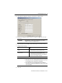
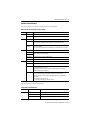
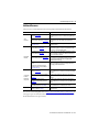
1
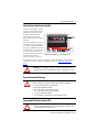
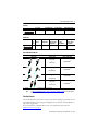
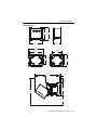
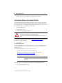
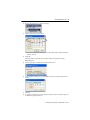
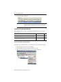
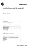
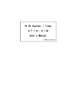
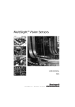
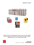
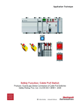
Installation Instructions
Original Instructions
Armor GuardLogix Controllers
Catalog Number 1756-L72EROMS
Topic
Page
Important User Information
2
About the Armor GuardLogix Controller
3
Prevent Electrostatic Discharge
3
Programmable Electronic Systems (PES)
3
Environment and Enclosure
4
Electrical Safety Considerations
4
Before You Begin
4
Install the Armor GuardLogix Controller
6
Mount the Controller
6
Ground the Controller
8
Open the Access Door
8
Remove and Install the Memory Card
8
Connect to the USB Port
9
Make Network Connections
10
Make Power Connections
11
Set the Network IP Address of the EtherNet/IP Modules
12
Update the Controller
17
Create a Controller Project
18
Status Indicators
18
Recover the Controller By Using a Memory Card
21
Specifications
22
Additional Resources
23
2 Armor GuardLogix Controllers
Important User Information
Read this document and the documents listed in the additional resources section about installation, configuration, and operation of
this equipment before you install, configure, operate, or maintain this product. Users are required to familiarize themselves with
installation and wiring instructions in addition to requirements of all applicable codes, laws, and standards.
Activities including installation, adjustments, putting into service, use, assembly, disassembly, and maintenance are required to be
carried out by suitably trained personnel in accordance with applicable code of practice.
If this equipment is used in a manner not specified by the manufacturer, the protection provided by the equipment may be impaired.
In no event will Rockwell Automation, Inc. be responsible or liable for indirect or consequential damages resulting from the use or
application of this equipment.
The examples and diagrams in this manual are included solely for illustrative purposes. Because of the many variables and
requirements associated with any particular installation, Rockwell Automation, Inc. cannot assume responsibility or liability for actual
use based on the examples and diagrams.
No patent liability is assumed by Rockwell Automation, Inc. with respect to use of information, circuits, equipment, or software
described in this manual.
Reproduction of the contents of this manual, in whole or in part, without written permission of Rockwell Automation, Inc., is
prohibited.
Throughout this manual, when necessary, we use notes to make you aware of safety considerations.
WARNING: Identifies information about practices or circumstances that can cause an explosion in a hazardous
environment, which may lead to personal injury or death, property damage, or economic loss.
ATTENTION: Identifies information about practices or circumstances that can lead to personal injury or death,
property damage, or economic loss. Attentions help you identify a hazard, avoid a hazard, and recognize the
consequence.
IMPORTANT Identifies information that is critical for successful application and understanding of the product.
Labels may also be on or inside the equipment to provide specific precautions.
SHOCK HAZARD: Labels may be on or inside the equipment, for example, a drive or motor, to alert people that
dangerous voltage may be present.
BURN HAZARD: Labels may be on or inside the equipment, for example, a drive or motor, to alert people that
surfaces may reach dangerous temperatures.
ARC FLASH HAZARD: Labels may be on or inside the equipment, for example, a motor control center, to alert
people to potential Arc Flash. Arc Flash will cause severe injury or death. Wear proper Personal Protective
Equipment (PPE). Follow ALL Regulatory requirements for safe work practices and for Personal Protective
Equipment (PPE).
Rockwell Automation Publication 1756-IN060C-EN-P - June 2015
Armor GuardLogix Controllers 3
About the Armor GuardLogix Controller
The Armor™ GuardLogix® controller
combines a 1756-L72S GuardLogix
controller and safety partner with
two Ethernet/IP DLR-capable
communication channels in an
IP67-rated housing for mounting on
a machine.
Display
Window
The Armor GuardLogix controller is
certified for use in safety applications
up to and including Safety Integrity
Level (SIL) 3 and Performance Level
(e) in which the de-energized state is
the safe state. The safety features of
the Armor GuardLogix controller are
derived from the sum of all
components within the enclosure.
Access
Door
Screws
For information on how to operate a GuardLogix controller-based system, safety application
requirements, and where to find the GuardLogix certificate, see Additional Resources on
page 23.
ATTENTION: In case of malfunction or damage, no attempts at repair should be made. The
controller should be returned to the manufacturer for repair. Do not dismantle the controller.
Prevent Electrostatic Discharge
ATTENTION: This equipment is sensitive to electrostatic discharge that can cause internal damage
and affect normal operation. Follow these guidelines when you handle this equipment.
• Touch a grounded object to discharge potential static.
• Wear an approved grounding wriststrap.
• Do not touch connectors or pins on component boards.
• Do not touch circuit components inside the equipment.
• Use a static-safe workstation if available.
• Store the equipment in appropriate static-safe packaging when not in use.
Programmable Electronic Systems (PES)
ATTENTION: Personnel responsible for the application of safety-related Programmable
Electronic Systems (PES) shall be aware of the safety requirements in the application of the
system and shall be trained in using the system.
Rockwell Automation Publication 1756-IN060C-EN-P - June 2015
4 Armor GuardLogix Controllers
Environment and Enclosure
ATTENTION: This equipment is intended for use in overvoltage Category II applications (as
defined in IEC 60664-1), at altitudes up to 2000 m (6562 ft) without derating.
This equipment is not intended for use in residential environments and may not provide
adequate protection to radio communication services in such environments.
This equipment is supplied as enclosed equipment. It should not require additional system
enclosure when used in locations consistent with the enclosure type ratings stated in the
Specifications section of this publication. Subsequent sections of this publication may contain
additional information regarding specific enclosure type ratings, beyond what this product
provides, that are required to comply with certain product safety certifications.
In addition to this publication, see the following:
• Industrial Automation Wiring and Grounding Guidelines, publication 1770-4.1, for
•
additional installation requirements
NEMA 250 and IEC 60529, as applicable, for explanations of the degrees of protection
provided by enclosures
Electrical Safety Considerations
ATTENTION: To comply with the CE Low Voltage Directive (LVD), all connections to this equipment
must be powered from a source compliant with the following:
• Safety Extra Low Voltage (SELV) Supply
• Protected Extra Low Voltage (PELV) Supply
To comply with UL/C-UL requirements, this equipment must be powered from a source compliant
with the following:
• IEC 60950-1 Ed. 2.1, Clause 2.2 - SELV Circuits
Before You Begin
Before you begin, check to make sure that you have all of the components that you need and plan
your network.
System Components
The controller ships with these parts installed:
• 1784-SD1 Secure Digital memory card, 1 GB
• 1747-KY key (shipped in a key holder inside the access door)
Control power and Ethernet communication cables are available separately.
Rockwell Automation Publication 1756-IN060C-EN-P - June 2015
Armor GuardLogix Controllers 5
Cordsets
(1)
No. of Pins
Assembly Rating
Straight Female
Right Angle Female
4
600V, 10 A
889N-F4AFC-(1)F
889N-R4AFC-(1)F
Replace (1) with 6 (6 ft), 12 (12 ft), or 20 (20 ft) for standard cable lengths.
Patchcords
(1)
No.
of
Pins
Assembly
Rating
Straight Female
Straight Male
Straight
Female, Right
Angle Male
Right Angle
Female,
Straight Male
Right Angle
Female, Right
Angle Male
4
600V, 10 A
889N-F4AFNM-(1)
889N-F4AFNE-(1)
889N-R4AFNM-(1)
889N-R4AFNE-(1)
Replace (1) with 1 (1 m), 2 (2 m), 5 (5 m), and 10 (10 m) for standard cable lengths.
Industrial Ethernet Media
M12 D Code
(1)
Patchcords and Cordsets IP67
Connector Type
Cat. No. Unshielded
Male Straight
to
Male Straight
1585D-M4TBDM-(1)
Male Straight
to
Male Right Angle
1585D-M4TBDE-(1)
Male Right Angle
to
Male Right Angle
1585D-E4TBDE-(1)
Male Straight
to
Female Straight
1585D-M4TBDF-(1)
Available in 0.3, 0.6, 1, 2, 5, 10, 15, and increments of 5 meters up to 75 meters.
TIP
See http://ab.rockwellautomation.com/Connection-Devices/EtherNet-Media for more information
on Industrial Ethernet Media.
Plan Your Network
The two EtherNet/IP networks in the enclosure let the Armor GuardLogix controller be used in
various EtherNet/IP network topologies, including linear, star, and device level ring (DLR) as a
ring node or ring supervisor.
For more information on EtherNet/IP networks, see the publications that are listed in
Additional Resources on page 23.
Rockwell Automation Publication 1756-IN060C-EN-P - June 2015
6 Armor GuardLogix Controllers
Install the Armor GuardLogix Controller
The controller ships with the power switch inside the enclosure set to ON and the controller in
Remote Program mode. You can make power connections and EtherNet/IP network
connections without opening the access door on the enclosure. However, if you need to access
the power switch, USB port, memory card, or key, you need to open the enclosure access door.
Follow these steps, described in this publication, to install the controller.
1. Mount the Controller
2. Ground the Controller
3. Open the Access Door, optional
4. Remove and Install the Memory Card, optional
5. Connect to the USB Port, optional
6. Make Network Connections
7. Make Power Connections
8. Set the Network IP Address of the EtherNet/IP Modules
9. Update the Controller
ATTENTION: Make sure that all connectors and caps are securely tightened to seal connections
properly against leaks and maintain IP67 requirements.
Mount the Controller
Observe these minimum spacing requirements
around the enclosure.
Mount the module directly to a machine by using
four mounting holes. The mounting hole diameter
on the mounting feet included with the enclosure is
6.8 mm (0.27 in.). Use four M6 screws and torque
screws to 6.6 N•m (58 lb-in). See the Product
Dimensions on page 7.
Rockwell Automation Publication 1756-IN060C-EN-P - June 2015
30 mm (1.18 in.)
30 mm (1.18 in.)
30 mm (1.18 in.)
Mounting feet can be attached in either horizontal
or vertical orientation as shown in Product
Dimensions on page 7. Attach the mounting feet to
the enclosure by using the four flat-head screws that
are supplied with the mounting feet. Torque screws
to 8.5 N•m (75.2 lb-in).
30 mm (1.18 in.)
Armor GuardLogix Controllers 7
Product Dimensions
240 mm 265 mm
(9.4 in.) (10.4 in.)
165mm
(6.5 in.)
292 mm
(11.5 in. )
327 mm
(12.9 in.)
215 mm
(8.5 in.)
298 mm
(11.7 in.)
172 mm
(6.8 in.)
245 mm
(10 in.)
Mounting feet in horizontal orientation
225.75 mm
8.9 in.
Mounting feet in vertical orientation
550 mm
21.7 in.
32.25 mm
1.3 in.
86.55 mm
3.4 in.
265 mm
10 in.
550 mm
21.7 in.
198.9 mm
7.8 in.
Clearance for access door opening
Rockwell Automation Publication 1756-IN060C-EN-P - June 2015
8 Armor GuardLogix Controllers
Ground the Controller
You must provide a proper grounding path by using the ground screw on the bottom of the
enclosure. To attach grounding wires, remove the screw and attach a ring lug, or loosen the screw
and slide a fork connector underneath. Tighten the screw.
PE Ground
Wire Size
Torque
1.3…5.2 mm2 (#16…#10 AWG)
2 N•m (17.7 in-lb)
See Industrial Automation Wiring and Grounding Guidelines, publication 1770-4.1 for
guidelines on how to install an industrial control system.
Open the Access Door
Open the enclosure door to access the power switch,
controller USB port, memory card, and key.
1. Loosen the four (captive) screws on the front
of the enclosure.
2. Gently lift the door and rotate it counterclockwise from the pivot at the lower left
corner.
Pivot Point
The door remains attached to the enclosure.
3. Close the access door on the enclosure and torque the four screws to 3.8 N•m
(33.5 lb-in).
IMPORTANT
When the access door is open, the Armor GuardLogix controller rating is Type 1.
Remove and Install the Memory Card
If you want to remove the memory card, follow these steps.
IMPORTANT
Verify that the memory-card status indicator is off
and that the card is not in use before removing it.
1. Open the enclosure door to access the controller.
2. Turn the keyswitch to the PROG position.
3. Press and release the memory card to eject it.
4. Remove the memory card.
5. Close the enclosure access door.
Rockwell Automation Publication 1756-IN060C-EN-P - June 2015
Armor GuardLogix Controllers 9
Follow these steps to install the memory card.
ATTENTION: If you are not sure of the contents of the memory card, before you install the
card, turn the keyswitch of the controller to the PROG position. Depending on the contents of
the card, a power cycle or fault could cause the card to load a different project or operating
system into the controller.
1. Open the access door on the enclosure.
2. Verify that the memory card is locked or unlocked according to your preference.
Unlocked
Locked
3. Insert the memory card into the memory card slot.
4. Gently press the card until it clicks into place.
5. Close the enclosure access door.
Connect to the USB Port
The controller has a USB port that uses a Type B receptacle. The port is USB 2.0-compatible and
runs at 12 Mbps. To use the USB port of the controller, you must have RSLinx® software, version
2.59.02 or later, installed on your workstation.
Access the USB port by opening the enclosure door.
Use a USB cable to connect your workstation to the USB port. With this connection, you can
update firmware and download programs to the controller directly from your workstation.
ATTENTION: The USB port is intended for only temporary local programming purposes and
not intended for permanent connection.
The USB cable must not exceed 3.0 m (9.84 ft) and must not contain hubs.
Rockwell Automation Publication 1756-IN060C-EN-P - June 2015
10 Armor GuardLogix Controllers
To configure RSLinx software to use a USB port, you must configure a USB driver. To configure
a USB driver, follow these steps. If you are using Windows 7 operating system, the driver is
automatically installed and you can go ahead to step 5.
1. Connect your controller and workstation by using a USB cable.
2. On the Found New Hardware Wizard dialog box, click one of the Windows Update
connection options and click Next.
TIP
If the software for the USB driver is not found and the installation is canceled, verify that you
have installed RSLinx Classic software, version 2.59.02 or later.
3. Click Install the software automatically (Recommended) and click Next.
4. Click Finish.
5. To browse to your controller in RSLinx software, click RSWho
.
In the RSLinx Workstation organizer, your controller appears under two different drivers, a
virtual chassis and the USB port. You can use either driver to browse to your controller.
Virtual Chassis Driver
USB Port Driver
Make Network Connections
1. Remove the dust caps from the four Ethernet connectors on the bottom of the enclosure.
IMPORTANT
If you disconnect network connections from these ports, reattach the dust caps and
finger-tighten.
2. Connect the cordsets that you selected to the Ethernet communication ports on the
bottom of the enclosure and torque to 1 N•m (9 lb-in).
D-Code M12 Female Network Connector
(View into Connector)
Pin 1 – M12_Tx+
Pin 2 – M12_Rx+
Pin 3 – M12_TxPin 4 – M12_RxPin 5 – Connector Shell Shield GND
5
1
2
4
3
44236
Rockwell Automation Publication 1756-IN060C-EN-P - June 2015
Armor GuardLogix Controllers 11
IMPORTANT
Use the 1585D–M4DC–H: Polyamide small body unshielded or the 1585D–M4DC–SH: Zinc
die-cast large body shielded mating connectors for the D-Code M12 female network connector.
IMPORTANT
Use two twisted-pair CAT5E UTP or STP cables.
D-Code M12 Pin
1
2
3
4
Wire Color
White-Orange
White-Green
Orange
Green
Signal
TX+
RX+
TXRX-
8-way Modular RJ45 Pin
1
3
2
6
Make Power Connections
Male Connector (Power Input)
Female Connector (Power Output)
Pin
1
2
3
4
Signal
V+ Switched
V+ Unswitched
V- Unswitched Common
V- Switched Common
The bottom of the enclosure has two sealed mini-style power connectors that operate in parallel
with one another to allow daisy-chaining of device power with other devices. The unit receives
its required power through the male connector. The female connector lets power be
daisy-chained to another ArmorStart®, Armor ControlLogix®, Armor GuardLogix or
On-Machine™ I/O product..
IMPORTANT On Machine end devices, such as the Armor GuardLogix controller, use the EN-50044 wiring
standard while On-Machine cordsets with flying leads use the SAE-J-1738A standard for wiring.
Use care to follow the pin numbering convention that is shown below before powering up the
unit.
Cordsets with Flying Leads (per SAE-J-1738A)
Female
Male
1-Black [V-] 2-White [E-] 3-Red [V+] 4-Green [E+]
Armor GuardLogix Controller (per EN 50044)
Female
Male
1-Red [V+] 2-Green [E+] 3- White [E-] 4-Black [V-]
1. Remove the dust cap from the female power connector on the bottom of the enclosure.
IMPORTANT
If you disconnect power connections from these ports, reattach the dust cap and
finger-tighten.
Rockwell Automation Publication 1756-IN060C-EN-P - June 2015
12 Armor GuardLogix Controllers
2. Make power connections and tighten to hand tight plus one half-turn.
Set the Network IP Address of the EtherNet/IP Modules
The EtherNet/IP communication modules reside in slots 2 and 3 of the ControlLogix chassis
within the enclosure. The modules are shipped with Bootstrap Protocol (BOOTP)/Dynamic
Host Configuration Protocol (DHCP) enabled and their rotary switches set to 999. You can use
the following methods to set the IP address of each module.
• BOOTP/DHCP server
• RSLinx Classic software
• Studio 5000 Logix Designer® application
ATTENTION: The EtherNet/IP communication module must be assigned a fixed network address.
The IP address of this module must not be dynamically provided.
Failure to observe this precaution can result in unintended machine motion or loss of process
control.
See the EtherNet/IP publications that are listed in Additional Resources on page 23 for detailed
information on setting an IP address.
Use a BOOTP/DHCP Server
The BOOTP/DHCP server is a standalone server that you can use to set an IP address. When
used, the BOOTP/DHCP server sets an IP address and other Transport Control Protocol
(TCP) parameters.
Access the BOOTP/DHCP server from one of these locations:
• Programs > Rockwell Software > BOOTP-DHCP Server
If you have not installed the server, you can download and install it from
http://www.ab.com/networks/ethernet/bootp.html.
• Tools directory on the Studio 5000® environment installation CD
IMPORTANT
Before you start the BOOTP/DHCP server, make sure that you have the hardware
(MAC) address of the module. The hardware address is on the label on the bottom of
the enclosure.
Follow these steps to set the IP address of the module by using a BOOTP/DHCP server.
1. Start the BOOTP/DHCP software.
Rockwell Automation Publication 1756-IN060C-EN-P - June 2015
Armor GuardLogix Controllers 13
2. From the Tools menu, choose Network Settings.
3. Type the Subnet Mask of the network.
The Gateway address, Primary and/or Secondary DNS address, and Domain Name
fields are optional.
4. Click OK.
The Request History panel shows the hardware addresses of all modules issuing
BOOTP requests.
5. Select the appropriate module and click Add to Relation List.
6. On the New Entry dialog box, type an IP Address, Hostname, and Description for the
module.
7. Click OK.
8. To assign this configuration to the module permanently, wait for the module to appear in
the Relation List panel and select it.
Rockwell Automation Publication 1756-IN060C-EN-P - June 2015
14 Armor GuardLogix Controllers
9. Click Disable BOOTP/DHCP.
IMPORTANT
If you do not click Disable BOOTP/DHCP, the host controller clears the current IP
configuration and begins sending BOOTP requests again each time that power is
cycled.
Use RSLinx or the Logix Designer Application
This table describes when to set the network IP address with RSLinx software or the Logix
Designer application.
Conditions
Use
Page
A BOOTP server is not available.
The EtherNet/IP communication module is connected to another NetLinx network.
RSLinx software
14
The Logix Designer project is online with a controller that communicates to or through
the EtherNet/IP communication module.
Logix Designer application
16
Set the Network IP Address with RSLinx Software
Follow these steps to use RSLinx software to set the IP address of the communication module.
1. From the Communications menu, choose RSWho.
2. From the RSWho dialog box, navigate to the Ethernet network.
3. Right-click the EtherNet/IP module and choose Module Configuration.
Rockwell Automation Publication 1756-IN060C-EN-P - June 2015
Armor GuardLogix Controllers 15
4. On the Module Configuration dialog box, click the Port Configuration tab.
5. For Network Configuration Type, click Static to assign this configuration to the port
permanently.
.
IMPORTANT
If you click Dynamic, on a power cycle, the controller clears the current IP
configuration and resumes sending BOOTP requests.
6. Type the IP address in the IP Address field and add complete more fields, if needed.
7. Configure the port settings.
To
Then
Use the default port speed and duplex
settings
Leave Auto-negotiate port speed and duplex checked.
This setting determines the actual speed and duplex setting.
Manually configure the speed and duplex
settings of your port
Follow these steps.
1. Clear the Auto-negotiate port speed and duplex checkbox.
2. From the Current Port Speed pull-down menu, choose a port speed.
3. From the Current Duplex pull-down menu, choose the appropriate
Duplex value, that is, half-duplex or full-duplex.
IMPORTANT
Consider the following when you configure the port settings:
• If the module is connected to an unmanaged switch, leave Auto-negotiate port
speed and duplex checked or communication can be impaired.
• If you are forcing the port speed and duplex with a managed switch, the
corresponding port of the managed switch must be forced to the same settings
or the module will fail.
8. Click OK.
Rockwell Automation Publication 1756-IN060C-EN-P - June 2015
16 Armor GuardLogix Controllers
Set the Network IP Address with the Logix Designer Application
Follow these steps to use the Logix Designer application to set the IP address of the module.
1. In the Controller Organizer, right-click the EtherNet/IP module and choose Properties.
2. On the Module Properties dialog box, click the Port Configuration tab.
3. In the IP Address field, type the IP address.
4. In the other fields, type the other network parameters, if needed.
IMPORTANT
The fields that appear vary from one EtherNet/IP module to another.
5. Click Set.
6. Click OK.
Rockwell Automation Publication 1756-IN060C-EN-P - June 2015
Armor GuardLogix Controllers 17
Update the Controller
The controller ships without firmware. Controller firmware is packaged with the Studio 5000
environment. In addition, controller firmware is also available for download from the Rockwell
Automation® Technical Support website at: http://www.rockwellautomation.com/support/.
You can update your firmware by using either ControlFLASH™ software or by using the
AutoFlash feature of the Logix Designer application.
Use ControlFLASH Software to Update Firmware
The safety partner updates automatically when the primary controller is updated.
IMPORTANT
If the memory card is locked and the Load Image option of the stored project is set to
On power up, the controller firmware is not updated as a result of these steps. Any previously
stored firmware and projects are loaded instead.
1. Verify that the appropriate network connection is made and the network driver has been
configured in RSLinx software.
2. Start ControlFLASH software.
3. Click Next.
4. Select the catalog number of the controller and click Next.
5. Expand the network until you see the controller.
6. Select the controller and click Next.
7. Select the revision level to which you want to update the controller and click Next.
8. To start the update of the controller, click Finish and then click Yes.
After the controller is updated, the status dialog box displays ‘Update complete’.
IMPORTANT
Allow the firmware update to complete fully before you cycle power or otherwise
interrupt the update. If the ControlFLASH update of the controller is interrupted, the
controller reverts to boot firmware, which is firmware revision 1.xxx, and you will
need to repeat the update process.
9. Click OK.
10. Close ControlFLASH software.
Rockwell Automation Publication 1756-IN060C-EN-P - June 2015
18 Armor GuardLogix Controllers
Use AutoFlash to Update Firmware
To update your controller firmware with the AutoFlash feature, follow these steps.
1. Verify that the appropriate network connection is made and your network driver is
configured in RSLinx software.
2. Use the Logix Designer application to create a controller project at the version you need.
3. Click RSWho to specify the controller path.
4. Select your controller and click Update Firmware.
5. Select the firmware revision that you want.
6. Click Update.
7. Click Yes.
Allow the firmware update to complete without interruption. When the firmware update is
complete, the Who Active dialog box opens. You can complete other tasks in the Logix Designer
application.
Create a Controller Project
To create an Armor GuardLogix controller project in the Studio 5000 Logix Designer
application, you add each component in the enclosure to the Controller Organizer as shown.
Status Indicators
Status indicators are visible through the window on the front of the enclosure.
Rockwell Automation Publication 1756-IN060C-EN-P - June 2015
Armor GuardLogix Controllers 19
Controllers Status Indicators
The status of the primary controller is displayed via four status indicators.
Primary Controller Status Indicator Descriptions
Indicator
Status
Description
RUN
Off
No user tasks running. Controller is in Program mode.
Green
Controller is in RUN mode.
Off
No forces, standard or safety, are enabled on the controller.
Amber
Standard and/or safety forces have been enabled.
Use caution if you install (add) a force. If you install a force, it takes immediate effect.
Amber,
Flashing
One or more I/O addresses, standard and/or safety, have been forced to an on or off state, but
forces are not enabled.
Use caution if you enable I/O forces. If you enable I/O forces, all existing I/O forces also take effect.
Off
No activity is occurring with the memory card.
Green, Flashing
The controller is reading from or writing to the memory card. Do not remove the memory card
while the controller is reading or writing.
FORCE
SD
Green
OK
Red, Flashing
The memory card does not have a valid file system.
Red
The memory card is not recognized by the controller.
Off
No power is applied.
Green
The controller is operating with no faults.
Red, Flashing
Nonrecoverable fault or recoverable fault that is not handled in the fault handler. All user tasks,
both standard and safety, are stopped.
If the controller is new, out-of-the-box, it requires a firmware update. The status display
indicates Firmware Installation Required.
Red
The controller is completing power-up diagnostics
A nonrecoverable major fault occurred and the program was cleared from memory.
The charge of the capacitor in the Energy Storage Module (ESM) is being discharged upon
powerdown.
The controller is powered but inoperable.
The controller is loading a project to nonvolatile memory.
The safety partner has an OK status indicator.
Safety Partner Status Indicator
Indicator
Status
Description
OK
Off
No power is applied.
Green
The safety partner is operating with no faults.
Red
Powering up or nonrecoverable controller fault.
Rockwell Automation Publication 1756-IN060C-EN-P - June 2015
20 Armor GuardLogix Controllers
Controller Status Display
The controller status display scrolls messages that provide information about the controller’s
firmware revision, energy storage module (ESM) status, project status, and major faults.
For a list of status messages, refer to the GuardLogix 5570 Controllers User Manual, publication
1756-UM022.
EtherNet/IP Module Status Indicators
The EtherNet/IP communication modules support these status indicators.
Indicator
Status
Description
Off
One of these conditions exists:
• The module is not powered.
– Verify that there is chassis power.
– Verify that the module is completely inserted into the chassis and backplane.
– Make sure that the module has been configured.
• No link exists on the port.
• The port is administratively disabled (LNK2).
• The port is disabled due to rapid ring faults (LNK2).
LINK 1,
LINK 2
OK
Flashing green
Activity exists on the port.
Green
One of these conditions exists:
• A link exists on the port.
• The ring network is operating normally on active ring supervisor (LNK2).
• A ring partial network fault was detected on the active ring supervisor (LNK2).
Off
The module is not powered.
• Verify that there is chassis power.
• Verify that the module is completely inserted into the chassis and backplane.
• Make sure that the module has been configured.
Flashing green
The module is not configured.
The Module Status display scrolls: BOOTP or DHCP<Mac_address_of_module>
For example: BOOTP 00:0b:db:14:55:35
Configure the module.
Green
The module is operating correctly.
The Module Status display scrolls: OK <IP_address_of_this_module>
For example: OK 10.88.60.160
Flashing red
The module detected a recoverable minor fault. Check the module configuration. If necessary,
reconfigure the module.
Red
The module detected an unrecoverable major fault. Cycle power to the module. If the power
cycle does not clear the fault, replace the module.
Red AND the
module status
display is scrolling
‘Image Update
Needed ‘
Follow these steps:
1. Update the firmware image.
2. Cycle power to the module.
3. If the status indicators remain the same, that is, red and scrolling Image Update Needed,
replace the module.
Flashing red and
green
The module is performing its power-up testing.
Module Status Display
Alphanumeric display that scrolls messages. For example, when a module is operating
normally, the display scrolls the IP address of the module.
Rockwell Automation Publication 1756-IN060C-EN-P - June 2015
Armor GuardLogix Controllers 21
Recover the Controller By Using a Memory Card
If you need to recover the controller, due to a corrupt program or other issue, you can do so by
creating a recovery memory card. This procedure requires the use of a second, user-supplied
1784-SD1 memory card. Perform this procedure on a separate controller that is not locked and is
not corrupt, or perform the procedure before downloading any project to your Armor
GuardLogix controller.
IMPORTANT
To avoid inadvertently over-writing your application program, you must not use the 1784-SD1
memory card that shipped installed in the Armor GuardLogix controller.
Follow these steps to create the recovery memory card.
1. Update the Armor GuardLogix controller to the desired firmware revision by following
the instructions in Update the Controller on page 17.
2. Remove the memory card that shipped with the controller by following the instructions
in Remove and Install the Memory Card on page 8.
3. Insert a new 1784-SD1 card.
Label this memory card ‘recovery’, so that you do not confuse it with the memory card that was
TIP
shipped with the controller.
4. Load a blank project into the controller, and make sure to check the box to store the
project to the memory card and load on power-up.
5. Remove the ‘recovery’ memory card and store it in a secure location.
6. Reinsert the memory card that shipped with the Armor GuardLogix controller by
following the instructions in Remove and Install the Memory Card on page 8.
Follow these steps to use the recovery memory card to recover the controller.
1. Remove the memory card that was shipped with the controller.
2. Insert the recovery memory card.
3. Cycle power to the controller.
The blank project on the recovery memory card overwrites the project in the controller.
Rockwell Automation Publication 1756-IN060C-EN-P - June 2015
22 Armor GuardLogix Controllers
Specifications
This section lists general specifications specific to the enclosure. Specifications for the
components in the Armor GuardLogix controller enclosure are in their respective Technical
Data publications, which are listed in Additional Resources on page 23.
Attribute
1756-L72EROMS
Input system power - unswitched (pins 2 and 3)
18 …32V DC @ 8 A
Input pass through power - switched (pins 1 and 4)
18…32V DC @ 8 A, SELV
Output external power - unswitched (pins 2 and 3)
18…32V DC @ 6 A
Output pass through power - switched (pins 1 and 4)(1)
18…32V DC @ 8 A, SELV
Enclosure type rating
Type 4/4x
Meets IP67 (when marked) with receptacle dust caps or cable
termination
Isolation voltage
30V (continuous), Basic Insulation Type, Power to enclosure, Ethernet
channels to Power, and non-redundant EtherNet channels to
non-redundant EtherNet channels.
No isolation between redundant Ethernet channels
Type tested at 707V DC for 60 s
Temperature, operating
0…60 °C (32…140 °F)
Weight, approx (without mounting feet)
7.15 kg (15.725 lb)
Dimensions (HxWxD), approx
240 x 292 x 164.52 mm (9.4 x 11.5 x 6.5 in.)
(1)
Output pass-through power is intended to power other On-Machine devices only.
ATTENTION: This equipment is certified for use only within the ambient air temperature range
of 0…60 °C (32…140° F). The equipment must not be used outside of this range.
Machinery Directive
The controllers are in conformity with the essential requirements of the Machinery Directive
(2006/42/EC) when installed in accordance with the instructions contained in the product
documentation. The following standards, and technical specifications have been applied as
indicated.
Standard/Technical Specification
EN 60204-1
Electrical equipment of machines
EN ISO 13849-1
Safety-related parts of control systems
EN 62061
Functional Safety of safety-related control systems
Rockwell Automation Publication 1756-IN060C-EN-P - June 2015
Armor GuardLogix Controllers 23
Additional Resources
These resources contain information about related products from Rockwell Automation.
Resource
Safety
Controllers
EtherNet/IP
Networks
Specifications
for Armor
GuardLogix
Components
Description
GuardLogix 5570 Controllers User Manual,
publication 1756-UM022
Provides information on how to install, configure, program, and
use GuardLogix 5570 controllers in Studio 5000 Logix Designer
projects.
GuardLogix 5570 Controller Systems Safety
Reference Manual, publication 1756-RM099
Provides information on safety application requirements for
GuardLogix 5570 controller in Studio 5000 Logix Designer
projects.
Product Certifications website,
http://www.ab.com
Provides declarations of conformity, certificates, and other
certification details.
Ethernet Design Consideration s Reference
Manual, publication ENET-RM002
Provides details about how to use EtherNet/IP communication
modules with Logix5000™ controllers and communicate with
other devices on the EtherNet/IP network.
EtherNet/IP Network Configuration User
Manual, publication ENET-UM001
Describes how you can use EtherNet/IP communication modules
with your Logix5000 controller and communicate with various
devices on the Ethernet network.
EtherNet/IP Embedded Switch Technology
Application Guide, publication ENET-AP005
Provides details about how to install, configure, and maintain
linear and Device Level Ring (DLR) networks by using Rockwell
Automation EtherNet/IP devices that are equipped with
embedded switch technology.
EtherNet/IP Media Planning and Installation
Manual
This manual is available from the Open
DeviceNet Vendor Association (ODVA) at:
http://www.odva.org.
Provides details about how to use the required media
components and how to plan for, install, verify, troubleshoot,
and certify your EtherNet/IP network.
1756 ControlLogix Controller Technical Data,
publication 1756-TD001
Provides product specifications, dimensions, environmental
data, and information on certifications for the Armor GuardLogix
controller.
1756 ControlLogix Communication Modules
Specifications Technical Data, publication
1756-TD003
Provides product specifications, dimensions, environmental
data, and information on certifications for the 1756-EN3TR
modules.
1756 ControlLogix Power Supplies
Specifications Technical Data, publication
1756-TD005
Provides product specifications, dimensions, environmental
data, and information on certifications for the 1756-PB72 power
supply.
1756 ControlLogix Chassis Specifications
Technical Data, publication 1756-TD006
Provides product specifications, dimensions, environmental
data, and information on certifications for the chassis.
Industrial Automation Wiring and Grounding
Guidelines, publication 1770-4.1
Provides general guidelines for installing a Rockwell Automation
industrial system.
You can view or download publications at http://www.rockwellautomation.com/literature/. To
order paper copies of technical documentation, contact your local Allen-Bradley distributor or
Rockwell Automation sales representative.
Rockwell Automation Publication 1756-IN060C-EN-P - June 2015
Rockwell Automation Support
Rockwell Automation provides technical information on the Web to assist you in using its products.
At http://www.rockwellautomation.com/support you can find technical and application notes, sample code, and links to software
service packs. You can also visit our Support Center at https://rockwellautomation.custhelp.com/ for software updates, support chats
and forums, technical information, FAQs, and to sign up for product notification updates.
In addition, we offer multiple support programs for installation, configuration, and troubleshooting. For more information, contact
your local distributor or Rockwell Automation representative, or visit http://www.rockwellautomation.com/services/online-phone.
Installation Assistance
If you experience a problem within the first 24 hours of installation, please review the information that's contained in this manual.
You can also contact a special Customer Support number for initial help in getting your product up and running.
United States or Canada
1.440.646.3434
Outside United States or
Canada
Use the Worldwide Locator at
http://www.rockwellautomation.com/rockwellautomation/support/overview.page, or contact your
local Rockwell Automation representative.
New Product Satisfaction Return
Rockwell Automation tests all of its products to help ensure that they are fully operational when shipped from the manufacturing
facility. However, if your product is not functioning and needs to be returned, follow these procedures.
United States
Contact your distributor. You must provide a Customer Support case number (call the phone number
above to obtain one) to your distributor to complete the return process.
Outside United States
Please contact your local Rockwell Automation representative for the return procedure.
Documentation Feedback
Your comments will help us serve your documentation needs better. If you have any suggestions on how to improve this document,
complete this form, publication RA-DU002, available at http://www.rockwellautomation.com/literature/.
Rockwell Automation maintains current product environmental information on its website at
http://www.rockwellautomation.com/rockwellautomation/about-us/sustainability-ethics/product-environmental-compliance.page.
Allen-Bradley, Armor, ArmorStart, ControlFLASH, ControlLogix, GuardLogix, Logix5000, On-Machine, Rockwell Automation, Rockwell Software, RSLinx, and Studio 5000 Logix
Designer are trademarks of Rockwell Automation, Inc.
EtherNet/IP is a trademark of ODVA.
Trademarks not belonging to Rockwell Automation are property of their respective companies.
Rockwell Otomasyon Ticaret A.Ş., Kar Plaza İş Merkezi E Blok Kat:6 34752 İçerenköy, İstanbul, Tel: +90 (216) 5698400
Publication 1756-IN060C-EN-P - June 2015
Supersedes Publication 1756-IN060B-EN-P - November 2013
PN-280745
Copyright © 2015 Rockwell Automation, Inc. All rights reserved. Printed in the U.S.A.