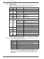
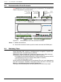
1
sigmadue microPAC M81
User Manual
User Manual
M.U. microPAC M81-1/12.11
Cod. ISTR-M M81ENG01
Sigmadue - microPAC M81 - User manual
Copyright © 2007, 2013 Ascon Tecnologic Srl
All rights reserved
No part of this document may be stored in a retrieval system, or transmitted in
any form, electronic or mechanical, without prior written permission of Ascon
Tecnologic Srl.
Ascon Tecnologic has used the best care and effort in preparing this manual and
believes that the information contained in this publication are accurate.
As Ascon Tecnologic continues to improve and develop products, the information
contained in this manual may also be subject to change.
Ascon Tecnologic reserves the right to change such information without notice.
Ascon Tecnologic makes no warranty of any kind, expressed or implied, with
regard to the documentation contained in this manual.
Ascon Tecnologic shall not be liable in any event - technical and publishing error
or omissions - for any incidental and consequential damages, in connection with,
or arising out of the use of this manual.
sigmadue®, gammadue® and deltadue®, are trademarks of Ascon Tecnologic Srl.
All other trade names or product names are trademarks or registered trademarks.
Ascon Tecnologic srl
Headquarters:
Phone:
Fax:
Internet Site:
E-mail address:
via Indipendenza 56,
27029 Vigevano (PV)
+39 0381 69871
+39 0381 698730
www.ascontecnologic.com
[email protected]
INDEX
Prerequisites . . . . . . . . . . . . . . . . . . . . . . . . . . . . . . . . . . . . . . . . . . . . .
Using this manual . . . . . . . . . . . . . . . . . . . . . . . . . . . . . . . . . . . . . . . . . . . . .
Current Documentation on the Internet . . . . . . . . . . . . . . . . . . . . . . . . . . . . .
Chapter 1
Technical data . . . . . . . . . . . . . . . . . . . . . . . . . . . . . . . . . . . . . . .
1-1
1-2
1-3
vii
vii
viii
1
General and environmental characteristics . . . . . . . . . . . . . . . . . .
Functional characteristics . . . . . . . . . . . . . . . . . . . . . . . . . . . . . . . .
I/O Characteristics . . . . . . . . . . . . . . . . . . . . . . . . . . . . . . . . . . . . . . .
1
1
2
1-3-1
1-3-2
1-3-3
1-3-4
1-3-5
Digital Inputs (DI1... DI12) . . . . . . . . . . . . . . . . . . . . . . . . . . . . . . .
Digital Outputs (D01... DI10) . . . . . . . . . . . . . . . . . . . . . . . . . . . . .
Analogue Inputs (AI1... AI12) . . . . . . . . . . . . . . . . . . . . . . . . . . . . .
Analogue Output (AO1... AO4) . . . . . . . . . . . . . . . . . . . . . . . . . . .
Auxiliary Analogue Output . . . . . . . . . . . . . . . . . . . . . . . . . . . . . . .
2
2
2
3
3
Communication ports . . . . . . . . . . . . . . . . . . . . . . . . . . . . . . . . . . . .
3
1-4-1
.............
3
Chapter 2
Hardware description . . . . . . . . . . . . . . . . . . . . . . . . . . . . . . . . .
5
1-4
2-1
Serial Communication ports (COM1 and COM2)
Architecture . . . . . . . . . . . . . . . . . . . . . . . . . . . . . . . . . . . . . . . . . . . .
6
2-1-1
2-1-2
2-1-3
Communication ports . . . . . . . . . . . . . . . . . . . . . . . . . . . . . . . . . . .
Integrated I/Os . . . . . . . . . . . . . . . . . . . . . . . . . . . . . . . . . . . . . . . .
Diagnostic LEDs . . . . . . . . . . . . . . . . . . . . . . . . . . . . . . . . . . . . . .
6
7
8
Chapter 3
Installation . . . . . . . . . . . . . . . . . . . . . . . . . . . . . . . . . . . . . . . . . .
9
3-1
3-2
Mechanical installation . . . . . . . . . . . . . . . . . . . . . . . . . . . . . . . . . . .
9
3-1-1
Installing and Removing the I/O expansion modules . . . . . . . . . . .
9
Electrical installation . . . . . . . . . . . . . . . . . . . . . . . . . . . . . . . . . . . . .
9
3-2-1
3-2-2
3-2-3
3-2-4
3-2-5
3-2-6
3-2-7
3-2-8
3-2-9
3-2-10
3-2-11
X1: Supply 24 VAC/DC Power Supply Connector . . . . . . . . . . . . .
X2, X3: DO1, DO2 Digital Output SPDT Relays (5A) . . . . . . . . . .
X4, X5, X6: DI1... DI12 Digital Input for Free Voltage Contacts . .
X7, X8: DO3... DO10 Digital Output SPST Relays (2A) . . . . . . . .
X9: Power Supply (15 VDC) for external devices . . . . . . . . . . . . .
X10, X11: Serial Communication Ports Connectors . . . . . . . . . . .
X12: AI1... AI4: High Level Analogue Inputs . . . . . . . . . . . . . . . . .
X13: AO1... AO4: Analogue Outputs . . . . . . . . . . . . . . . . . . . . . . .
X14...X15: AI5... AI12: Temperature 2 Wires Analogue Inputs . . .
X16: LAN Ethernet 10baseT Connector . . . . . . . . . . . . . . . . . . . .
X17: USB Flash Drive Connector . . . . . . . . . . . . . . . . . . . . . . . . .
9
9
9
10
10
10
10
11
11
11
11
iii
Index (continued)
Chapter 4
Communication Ports Configuration
....................
13
Configuring the optional serial communications ports . . . . . . . . .
13
4-1-1
Configuring the COM1Port . . . . . . . . . . . . . . . . . . . . . . . . . . . . . . .
14
Connect the Setup Terminal . . . . . . . . . . . . . . . . . . . . . . . . . . . . . . .
15
4-2-1
4-2-2
Telnet Communications Connection . . . . . . . . . . . . . . . . . . . . . . .
Connect the serial setup terminal . . . . . . . . . . . . . . . . . . . . . . . . . .
15
16
Configuring the Modbus Connections . . . . . . . . . . . . . . . . . . . . . . .
17
4-3-1
4-3-2
Configuring the COM2 Modbus Port . . . . . . . . . . . . . . . . . . . . . . .
Connecting the Modbus Ports . . . . . . . . . . . . . . . . . . . . . . . . . . . .
17
18
Chapter 5
CPU Configuration Session . . . . . . . . . . . . . . . . . . . . . . . . . . . .
19
4-1
4-2
4-3
5-1
Connect the Setup Terminal . . . . . . . . . . . . . . . . . . . . . . . . . . . . . . .
19
5-1-1
Starting the Configuration Session . . . . . . . . . . . . . . . . . . . . . . . . .
20
CPU Main Menu . . . . . . . . . . . . . . . . . . . . . . . . . . . . . . . . . . . . . . . . .
20
5-2-1
5-2-2
5-2-3
5-2-4
5-2-5
5-2-6
5-2-7
5-2-8
5-2-9
5-2-10
5-2-11
5-2-12
5-2-13
5-2-14
5-2-15
5-2-16
5-2-17
Network Setup Menu . . . . . . . . . . . . . . . . . . . . . . . . . . . . . . . . . . .
Ethernet Setup Menu . . . . . . . . . . . . . . . . . . . . . . . . . . . . . . . . . . .
Serial Setup Menu . . . . . . . . . . . . . . . . . . . . . . . . . . . . . . . . . . . . .
CPU Setup Menu . . . . . . . . . . . . . . . . . . . . . . . . . . . . . . . . . . . . . .
Startup Setup Menu . . . . . . . . . . . . . . . . . . . . . . . . . . . . . . . . . . . .
Persistency Setup Menu . . . . . . . . . . . . . . . . . . . . . . . . . . . . . . . .
RTC Clock Setup Menu . . . . . . . . . . . . . . . . . . . . . . . . . . . . . . . . .
Retain Config . . . . . . . . . . . . . . . . . . . . . . . . . . . . . . . . . . . . . . . . .
Modbus TCP/IP Setup . . . . . . . . . . . . . . . . . . . . . . . . . . . . . . . . . .
Modbus TC/IP Secure Addresses Table Menu . . . . . . . . . . . . . . .
Modbus TC/IP Priority Addresses Table Menu . . . . . . . . . . . . . . .
Local I/O Setup Menu . . . . . . . . . . . . . . . . . . . . . . . . . . . . . . . . . . .
Setting the I/O Channels . . . . . . . . . . . . . . . . . . . . . . . . . . . . . . . .
AO Channel 1 & Channel 2 Menu . . . . . . . . . . . . . . . . . . . . . . . . .
AO Channel 3 & Channel 4 Menu . . . . . . . . . . . . . . . . . . . . . . . . .
Internal Temperature Menu . . . . . . . . . . . . . . . . . . . . . . . . . . . . . .
CPU Info Menu . . . . . . . . . . . . . . . . . . . . . . . . . . . . . . . . . . . . . . . .
21
21
21
22
23
23
24
24
26
26
27
27
28
30
31
32
32
Chapter 6
USB Mass Storage Device . . . . . . . . . . . . . . . . . . . . . . . . . . . . .
35
5-2
6-1
Configuring the CPU with the USB Mass Storage Device . . . . . . .
35
6-1-1
6-1-2
6-1-3
6-1-4
Boostrap sequence . . . . . . . . . . . . . . . . . . . . . . . . . . . . . . . . . . . .
Upload of the status, configuration and program files from the PLC
Download of the status, configuration and program files in the PLC
File system support for the PLC application . . . . . . . . . . . . . . . . . .
35
36
36
36
Chapter 7
CPU Diagnostic Tests . . . . . . . . . . . . . . . . . . . . . . . . . . . . . . . . .
39
7-1
7-2
iv
Accessing the diagnostic session . . . . . . . . . . . . . . . . . . . . . . . . . .
I/O Watch Window . . . . . . . . . . . . . . . . . . . . . . . . . . . . . . . . . . . . . . .
39
40
Index (continued)
Chapter 8
Programming the CPU
8-1
8-2
8-3
8-4
41
Installing OpenPCS . . . . . . . . . . . . . . . . . . . . . . . . . . . . . . . . . . . . . .
41
8-1-1
8-1-2
8-1-3
8-1-4
Hardware and Software Requirements . . . . . . . . . . . . . . . . . . . . .
Installation . . . . . . . . . . . . . . . . . . . . . . . . . . . . . . . . . . . . . . . . . . .
Starting OpenPCS . . . . . . . . . . . . . . . . . . . . . . . . . . . . . . . . . . . . .
Configuring OpenPCS . . . . . . . . . . . . . . . . . . . . . . . . . . . . . . . . . .
41
41
41
42
OpenPCS Setup . . . . . . . . . . . . . . . . . . . . . . . . . . . . . . . . . . . . . . . . .
Communication Ports Protocols . . . . . . . . . . . . . . . . . . . . . . . . . . .
Watchdog Timer . . . . . . . . . . . . . . . . . . . . . . . . . . . . . . . . . . . . . . . . .
42
44
44
Chapter 9
CPU TFTP File Access
9-1
9-2
................................
................................
TFTP Protocol Access . . . . . . . . . . . . . . . . . . . . . . . . . . . . . . . . . . . .
IEC61131-3 OpenPCS Runtime Errors log file . . . . . . . . . . . . . . . .
Chapter 10
CPU Data Memory Map . . . . . . . . . . . . . . . . . . . . . . . . . . . . . . . .
10-1 Central Unit Data . . . . . . . . . . . . . . . . . . . . . . . . . . . . . . . . . . . . . . . .
10-1-1
10-1-2
10-1-3
10-1-4
10-1-5
10-1-6
10-1-7
10-1-8
45
45
46
49
49
Digital Inputs Status (DI1... DI12) . . . . . . . . . . . . . . . . . . . . . . . . .
High Level Analogue Inputs (AI1... AI4) . . . . . . . . . . . . . . . . . . . . .
Temperature Analogue Input Value (AI5... AI12) . . . . . . . . . . . . . .
I/O Diagnostic Status . . . . . . . . . . . . . . . . . . . . . . . . . . . . . . . . . . .
Onboard Temperature Values . . . . . . . . . . . . . . . . . . . . . . . . . . . .
Digital Counters . . . . . . . . . . . . . . . . . . . . . . . . . . . . . . . . . . . . . . .
Digital Outputs Status (DO1... DO10) . . . . . . . . . . . . . . . . . . . . . .
Analogue Output Value (AO1... AO4) . . . . . . . . . . . . . . . . . . . . . .
49
50
50
51
51
52
52
52
10-2 Battery and Retentive Memory Status,
I/O Configuration Information . . . . . . . . . . . . . . . . . . . . . . . . . . . . . .
53
10-2-1
10-2-2
10-2-3
Battery and Retentive Memory Status . . . . . . . . . . . . . . . . . . . . . .
I/O Configuration Information . . . . . . . . . . . . . . . . . . . . . . . . . . . . .
Production Code Management Variables . . . . . . . . . . . . . . . . . . .
53
53
54
10-3 Complete Memory Map . . . . . . . . . . . . . . . . . . . . . . . . . . . . . . . . . . .
55
10-3-1
10-3-2
10-3-3
Input Memory Areas . . . . . . . . . . . . . . . . . . . . . . . . . . . . . . . . . . .
Output Memory Areas . . . . . . . . . . . . . . . . . . . . . . . . . . . . . . . . . .
Marker Memory Areas . . . . . . . . . . . . . . . . . . . . . . . . . . . . . . . . . .
55
56
56
v
Index (continued)
Chapter 11
Ascon Tecnologic Function Blocks Libraries
.............
59
AT_Generic_Advanced_Lib . . . . . . . . . . . . . . . . . . . . . . . . . . . . . . .
AT_Process_Generic_Lib . . . . . . . . . . . . . . . . . . . . . . . . . . . . . . . . .
AT_Process_Control_Lib . . . . . . . . . . . . . . . . . . . . . . . . . . . . . . . . .
AT_Communications_Lib . . . . . . . . . . . . . . . . . . . . . . . . . . . . . . . . .
Firmware Function Blocks List . . . . . . . . . . . . . . . . . . . . . . . . . . . . .
59
60
60
61
62
Appendix A
Reference documents . . . . . . . . . . . . . . . . . . . . . . . . . . . . . . . . .
65
11-1
11-2
11-3
11-4
11-5
vi
Prerequisites
The products described in this manual should be installed, operated and
maintained only by qualified application programmers and software engineers who
are familiar with EN 61131-3 concepts of PLC programming, automation safety
topics, and applicable national standards.
Using this manual
Specifications within the text of this manual are given in the International System
of Units (SI), with non SI equivalents in parentheses.
Fully Capitalized words within the text indicate markings found on the equipment.
Words in bold style within the text indicate markings found in the Configuration Tools.
Warnings, Cautions and Notes are used to emphasize critical instructions:
DANGER!
Indicates an imminently hazardous situation which, if not avoided, will result in
death or serious injury.
WARNING
Indicates a potentially hazardous situation which, if not avoided, could result in
death or serious injury.
Caution
Indicates a potentially hazardous situation which, if not avoided, may result in
minor or moderate injury, or property damage.
Note: Highlights important information about an operating procedure or the equipment.
vii
Sigmadue - microPAC M81 - User manual
Current Documentation on the Internet
Make sure you are always working with the latest version of this document.
Ascon Tecnologic Srl reserves the right to make changes to its products in the
name of technological advancement. New documents revisions, when published
can be found online at:
http://www.ascontecnologic.com
viii
Chapter 1
Technical data
1-1
General and environmental characteristics
Features
Power supply
Power consumption
Operating temperature
Storage temperature
Relative Humidity
Protection degree
Mounting
Dimensions
Weight
Protection Degree
Safety
Approvals
1-2
Description
24 Vac/dc (-15... +25%)
10 W (+5 W with I/O modules)
0… 50°C
-40… 70°C
5... 95% non condensing
IP20
DIN rail
L: 175 mm, H: 110 mm, D: 60 mm
450g
IP20
Compliance to EN 61131-2
Isolation class II (50Vrms), EN61010-1
CE, UL and cUL (pending)
Functional characteristics
Features
Description
Programming languages
Program memory
Dynamic memory
Retentive memory
Data retention (for power failure)
Min. cycle time
Max. timer resolution
Real Time Clock
IL, ST, FBD, LD, SFC, CFC
Max. 2 MB internal, 3.5 MB on USB key
16 MB
64 kB redundant
10 years (for Flash memory)
Typical 10ms
1 ms
Yes
Unlimited, application dependent, suggested
up to 20
Max. P.I.D. number
1
Sigmadue - microPAC M81 - User manual
1-3
I/O Characteristics
1-3-1
Digital Inputs (DI1... DI12)
Features
Input type
Isolation
Compliance
Output connectors
1-3-2
Relay Outputs
DO1 and DO2
Description
For free of voltage contacts (contact closure)
800V channels-power supply
800V channels-logic components
IEC/EN 61131-2 (type 1)
X4, X5 and X6
Digital Outputs (D01... DI10)
DO1 and DO2 are relay outputs with SPDT (Single Pole, Double Throw) contacts
configuration. The characteristics are:
Features
Contact configuration
Contact rate
Isolation
Output connectors
Relay Outputs
DO3... DO10
Description
SPDT (Single Pole, Double Throw)
5 A (for resistive loads)
2500V between channel and Power Supply and
between channel and main electronics
X2 and X3
DO3... DO10 are 8 relay outputs with SPST (Single Pole, Single Throw, Normally
Open) contacts configuration. The characteristics are:
Features
Contact configuration
Contact rate
Isolation
Output connectors
SPST (Single Pole, Single Throw)
2 A (for resistive loads)
2500V between channel and Power Supply and
between channel and main electronics
X7 and X8
Note:
The output of the watchdog timer function can be addressed to the DO3 relay
output.
1-3-3
Analogue Inputs (AI1... AI12)
High level
Analogue Inputs
AI1... AI4
AI1... AI4 are 4 High Level Analogue Inputs that can be configured through the
Setup masks. The characteristics of these Inputs are:
Features
Type of input
Resolution
Accuracy
Input inpedance
Isolation
Input connectors
2
Description
Description
0/1... 5 V, 0/2... 10 V, Ratiometric (with 5 V reference)
and 0/4... 20 mA
16 bit
±0.5 %
>100kΩ (V); <300Ω (mA)
2500V between channel and Power Supply and
between channel and main electronics
X12
Chapter 1 - Technical data
Temperature
Analogue Inputs
AI5... AI12
AI5... AI12 are 8 Temperature Analogue Inputs that can be configured through the
Setup masks. The characteristics of these Inputs are:
Features
Type of input
Resolution
Accuracy
Isolation
Input inpedance
Input connectors
1-3-4
Description
Pt1000, NTC SEMITEC 103AT-2, NTC Custom
16 bit
±1%
800V channels-power supply
800V channels-logic components
>10MΩ
X14 and X15
Analogue Output (AO1... AO4)
Features
AO1... AO4 [note 2]
Load
Resolution
Accuracy
Isolation
Connector
Description
0... 10 V
>1 kΩ
16 bit
±0.5%
800V channel-power supply
50V channel-main electronics
X13
Notes: 1. All the available input types are listed at:
“Setup Temperature Channels” on page 29 and
“Setup the Selected AI Channel” on page 28.
2. All the available output types are listed at:
“AO Channels Setup Menu” on page 31.
1-3-5
Auxiliary Analogue Output
Features
Power output 1
Power output 2
Power output 3
1-4
Description
+5 VDC
30 mA max.
X12
+12 VDC
80 mA max.
X12
+15 VDC
200 mA max.
X9
Output Voltage
Max load
Output connector
Output Voltage
Max load
Output connector
Output Voltage
Max load
Output connector
Communication ports
1-4-1
Serial Communication ports (COM1 and COM2)
Features
Isolation
Connector
Description
800V between the com port and main electronics
X10 and X11
3
Sigmadue - microPAC M81 - User manual
4
Chapter 2
Hardware description
The system described in this User Manual is mainly composed by:
• Ascon Tecnologic sigmadue microPAC M81 CPU with 8 analogue temperature
inputs (NTC, Pt1000), 4 high level analog inputs (0/4... 20 mA, 0... 10 V,
0... 5V ratiometric), 12 free voltage inputs, up to 4 (0/10V) analogue outputs,
2 x Normally Closed (Form C) SPDT (5A) and 8 x Normally Open (Form A)
SPST (2A) Relay Outputs.
• sigmadue I/O ModBus modules;
• Infoteam OpenPCS programming tool system.
microPAC M81 is a powerful processing device based on an ARM RISC 32 bit processor, with different memory types, onboard I/Os and up to 3 communication ports.
sigmadue I/O is a family of I/O analogue and digital modules with special functions
that can be also connected to the M81 module through a dedicated ModBus RTU
serial bus.
Infoteam OpenPCS is a powerful and useful standard EN61131-3 compliant
programming tool for PLC applications.
It is a clearly structured and easily operated tool to edit, compile, debug, manage
and print PLC applications during all the development phases.
OpenPCS runs on Windows server 2003, Windows XP SP2, Windows Vista (32
bit) and Windows 7 (32 or 64 bit) platforms
The Ascon Tecnologic M81 unit based on sigmadue microPAC line, combines its
functionalities with the capabilities of a PLC. “Modular concept” means that you
can adapt the system quickly and easily to your requirements. This gives the
sigmadue automation systems an amazing price/performance ratio.
This User Manual handbook introduces you to the microPAC line and the Infoteam
OpenPCS programming tool.
It explains how to install the hardware and software and how to start up the system.
Information on maintenance, troubleshooting and services are also included.
5
Sigmadue - microPAC M81 - User manual
2-1
Architecture
From the programmer’s point of view, a complete system can be arranged as in
“Figure 2.1 - Programming the sigmadue M81 Control Unit” below:
Programming/
Configuration
station
Configuration
station
VT100
Ethernet
10 Mbit base T
RS232/485
Service port
sigmaPAC M81
CPU + 34 I/O
Input
sensor(s)
Output
Power
Controller
Figure 2.1 - Programming the sigmadue M81 Control Unit
In “Figure 2.1 - Programming the sigmadue M81 Control Unit” the configuration
station (VT100 terminal) and the PC with OpenPCS are displayed as two different
devices, but it is possible to use just one PC to run both OpenPCS and a VT100
emulator (e.g. PuTTY/HyperTerminal).
2-1-1
Communication ports
The CPU has 3 communication ports (see “Chapter 2 - Control Unit Supply, I/O and
Communication Ports”):
• One Ethernet port (TCP/IP) to be used for the connection to the PC for:
- CPU configuration using a telnet session;
- Programming, debugging and commissioning;
- Modbus TCP data exchange;
• One Service RS232/485 port (connector X10) to be used as:
- Standard ASCII serial port;
- Modbus RTU master/slave data exchange port.
• One RS485 port (connector X11) to be used as:
- Standard ASCII serial port;
- Modbus RTU master/slave data exchange port.
• One USB port for data logging and backup/restore functions (uploading or
downloading the configuration and the programs to/from an external USB
mass memory storage).
Pinout of all communication ports is described hereafter and in:
“M81 Installation Manual” [9].
6
Chapter 2 - Hardware Description
2-1-2
Integrated I/Os
The M81 base unit can house up to 36 I/O ports:
8 AI Analogue temperature inputs configurable for NTC, Pt1000 (connectors
X14 - X15);
4 AI High level isolated analogue inputs configurable for: 0/1... 5 V,
0/2... 10 V, Ratiometric (5 V reference) and 0/4... 20 mA (connector X12);
4 AO High level analogue outputs 0...10 V (connector X13);
12 DI General purpose Digital Inputs for Free Voltage Contacts (connectors X4... X6);
2 DO Isolated General Purpose SPDT 5A Relay Outputs (connectors X2... X3);
8 DO Isolated General Purpose SPST NO 2A Relay Outputs (connectors X7... X8).
Digital Outputs
8 SPST NO
relays (2A)
Ethernet 10 Base T
port (LAN) +
2 LAN status LEDs
C DO3 DO4 C DO5 DO6 C DO7 DO8 C DO9 DO10
X7
X8
Analogue
inputs
C AI5 AI6 AI7 AI8 C AI9 AI10 AI11 AI12
X14
X15
Power supply
(15 VDC) for
external devices
M +15
X9
ETHERNET
X16
RS232/485
Communication/
Configuration
RS485
Modbus
Rx Tx GND D+ D- D+ D- GND
X10 COM1
X11 COM2
USB
X17
USB Port
Expansion
bus
connector
Analogue
outputs
Analogue Inputs
+
External sensors
power supply
+5 and +12 VDC
M81
(CAN)
ERR RUN
L1 USB COM2 COM1 MSG RUN PWR
X12
X13
M AI1 AI2 AI3 AI4 +5 +12 AO1 AO2 M M AO3 AO4
X1 Supply
24 VAC/VDC
Power Supply
+24 VAC/DC
X2 DO1
X3 DO2
C NO NC C NO NC
X4
X5
X6
M DI1 DI2 DI3 DI4 M DI5 DI6 DI7 DI8 M DI9 DI10 DI11 DI12
Digital Outputs 2
SPDT relays (5 A)
Diagnostics
LEDs
• = L1
• = USB
• = COM2
• = COM1
• = MSG
• = RUN
• = PWR
Push
Button (PB)
Digital Inputs up to 12 inputs
for free voltage contacts
Figure 2.2 - Control Unit Supply, I/O and Communication Ports
WARNING
The PB button performs different operations accorndingly to the system status but
does not restart the CPU or the 1131 application.
WARNING
1)
2)
3)
At Power ON, if the PB button is pressed the stored setup parameters are
restored the factory defaut (as well as those set by the user).
Then, a phase while is possible to manage the upload/download of the status,
configuration and program files from/to the USB Key as described in the
“Chapter 6 - USB Mass Storage Device”.
While the PLC program is running, the PB behaves as a Standard Input
as described in “Chapter 10 - Digital Inputs Status (DI1... DI12)”.
7
Sigmadue - microPAC M81 - User manual
2-1-3
Diagnostic LEDs
Referring to “Figure 2.2 - Control Unit Supply, I/O and Communication Ports” a
description of the LEDs functions is given in the table below.
LED Colour Action (note 1)
Description
PWR
Blue
ON
Power Supply present
RUN LED during the normal PLC operations
ON
1131 program running
RUN
Green
OFF
1131 program stopped or not present
RUN + MSG LEDs
GREEN Flickering
RUN
Green
Configuration
RED Flickering
GREEN Flickering
MSG
Red
Watch Monitor
RED OFF
MSG LED during the normal PLC operations
OFF
Normal Opeartion
CRC error in the configuration file, reset to
Single flash
default
Double flash
Flash File System error
MSG
Red
Triple flash
Checksum VAR % RETAIN error (note 2)
Blinking
Backup battery low
Flickering
Checksum error in RETAIN data
OFF
PLC in Configuration or Watch monitor
COM1 Green
Normal PLC operation, data traffic on COM1
Blinking
OFF
PLC in Configuration or Watch monitor
COM2 Green
Normal PLC operation, data traffic on COM2
Blinking
ON
USB Mass Storage Device Inserted
RUN
Green Blinking
Access to the USB Mass Storage Device
USB
OFF
USB Mass Storage Device not present
ERR/L1 Red
ON/OFF
The LED can be managed by the application
Table 2.1 - Diagnostics LEDs description
Notes: 1. As the ON/OFF sequence of the LEDs has a specific meaning, it is important
that the user recognizes each LED status:
Sequence
OFF
Steady ON
Blinking
Flickering
Single flash
Double flash
Triple flash
Meaning
The LED is not lit
The LED is lit in a stable way
The LED blinks at a frequence of 2.5 Hz (slow)
The LED blinks at a frequence of 10 Hz (fast)
The LED lits once for at least 200 ms
The LED lits twice with pulses of 200 ms each
The LED lits three with pulses of 200 ms each
2. The first time %M variables have been defined as RETAIN (see “Chapter 5 Retain Config Menu”), the system needs to reboot in order to properly create the
dedicated files. The error indication will disappear automatically in case of
positive result.
8
Chapter 3
Installation
3-1
Mechanical installation
The sigmadue microPAC M81 unit and the additional external expansion I/O units
are designed to be installed on standard DIN rails.
The M81 unit has the expansion port connector on the right side of the case. For this
reason, consider to keep enough space in case of needs of expansion modules.
Up to two additional external expansion I/O units can be connected in chain to the M81.
3-1-1
Installing and Removing the I/O expansion modules
A complete description on how the modules can be mounted on or removed from the
system can be found in the “M81 Installation Manual” [9].
3-2
Electrical installation
Refer to: “Figure 2.2 - Control Unit Supply, I/O and Communication Ports” and
“M81 Installation Manual” [9] for details.
3-2-1
X1: Supply 24 VAC/DC Power Supply Connector
This 2 terminals connector brings the Power Supply to the CPU. They have no
polarity as the 24 V Power Supply can be in Direct or Alternate Current.
3-2-2
X2, X3: DO1, DO2 Digital Output SPDT Relays (5A)
These 3 terminal connectors are the output ports of the DO1 and DO2 SPDT relays.
The terminals of both the connectors have the following Pinout:
Label
C
Signal Common
3-2-3
NO
Normally Open position
NC
Normally Close position
X4, X5, X6: DI1... DI12 Digital Input for Free Voltage Contacts
These connectors are the input terminals of the DI1... DI12 for free voltage
contacts Digital Inputs. The connectors have the following pinout:
X4 Connector
DI1... DI4 - Digital Inputs
Label
M
Signal Common
X5 Connector
DI1
DI1 Input
DI2
DI2 Input
DI3
DI3 Input
DI4
DI4 Input
DI6
DI6 Input
DI7
DI7 Input
DI8
DI8 Input
DI5... DI8 - Digital Inputs
Label
M
Signal Common
DI5
DI5 Input
9
Sigmadue - microPAC M81 - User manual
X6 Connector
DI9... DI12 - Digital Inputs
Label
M
Signal Common
3-2-4
DI9
DI9 Input
DI10
DI10 Input
DI11
DI11 Input
DI12
DI12 Input
X7, X8: DO3... DO10 Digital Output SPST Relays (2A)
These connectors are the output terminals of the DO1... DO10 SPST relays.
The connectors have the following pinout:
X7 Connector
DO3... DO6 - Digital Outputs
Label
C
DO3
DO4
C
DO5
DO6
Signal Common DO3 Output DO4 Output Common DO5 Output DO6 Output
X8 Connector
DO7... DO10 - Digital Outputs
Label
C
DO7
DO8
C
DO9
DO10
Signal Common DO7 Output DO8 Output Common DO9 Output DO10 Output
3-2-5
X9: Power Supply (15 VDC) for external devices
The maximum load applicable to this output is 3 W.
The connectors have the following pinout:
Label
M
Signal 0 V
3-2-6
+15
+15 VDC
X10, X11: Serial Communication Ports Connectors
Through these 2 connectors is possible to connect 2 different serial communication ports. Some parameters of these ports can be configured using the switches
of the DIP switch block located close to the X10 connector (see the Installaton
Manual for more information).
X10
Connector
COM1 - RS232/485 Port
The X10 connector allows to connect an RS232/485 terminal (also for setup purposes). Through this port, using the protocol Modbus (master/slave) or serial ASCII
the PLC can connect a fieldbus network. The connector has the following pinout:
Label
RX
TX
GND
D+
DSignal RX (RS232) TX (RS232) GND (RS232/RS485) D+ (RS485) D- (RS485)
X11
Connector
COM2 - RS485 Port
Connector X11: RS485 port to connect a fieldbus network using the Modbus protocol (master/ slave) or serial ASCII. The connector has the following pinout:
Label
D+
Signal D+ (RS485)
3-2-7
DD- (RS485)
GND
GND (RS485)
X12: AI1... AI4: High Level Analogue Inputs
X12 is used to connect up to 4 High Level Analogue Inputs (AI1... AI4) to the system
(types: 0/1... 5 V, 0/2... 10 V, ratiometric with 5 V reference, 0/4... 20 mA). On the
connector are present also two different voltage outputs that can be used to power
external sensors/transmitters. The connector has the following pinout:
Label
M
AI1
AI2
AI3
AI4
+5
+12
Signal Common (-) AI1 Input AI2 Input AI3 Input AI4 Input +5 VDC +12 VDC
10
Chapter 3 - Installation
3-2-8
X13: AO1... AO4: Analogue Outputs
X13 is used to connect up to 4 Analogue Outputs (AO1... AO4) to the system (type:
0... 10 V). The connector has the following pinout:
Label
AO1
Signal +AO1
3-2-9
AO2
+AO2
M
M
AO3
Common (-) Common (-) +AO3
AO4
+AO4
X14...X15: AI5... AI12: Temperature 2 Wires Analogue Inputs
X14 and X15 are used to connect up to 8 Temperature Analogue Inputs (AI5... AI12) to
the system (types: NTC, Pt1000 all with two wires connection). The connectors have
the following pinout:
X14
Connector
AI5... AI8 - Temperature Analogue Input
X15
Connector
AI9... AI12 - Temperature Analogue Input
Label
C
Signal Common
Label
C
Signal Common
AI5
AI5 Input
AI9
AI9 Input
AI6
AI6 Input
AI10
AI10 Input
AI7
AI7 Input
AI8
AI8 Input
AI11
AI11 Input
AI12
AI12 Input
3-2-10 X16: LAN Ethernet 10baseT Connector
The X16 connector is a standard Ethernet RJ45 type.
3-2-11 X17: USB Flash Drive Connector
The X17 connector is a standard USB Type A receptacle to connect a flash drive
(system files upload or data logging download).
11
Sigmadue - microPAC M81 - User manual
12
Chapter 4
Communication Ports Configuration
The M81 system unit has 3 different communication ports (see “Figure 2.2 - Control Unit Supply, I/O and Communication Ports” for details):
X10 COM1 can be set, through the DIP switches, as RS232 or RS485 and can be
used to configure the Basic Unit and for Modbus communications;
X11 COM2 is an RS485 dedicated to Modbus communications.
X16 Ethernet port (TCP/IP) used to configure, program, debug, commission and
for Modbus TCP data exchange.
4-1
Configuring the optional serial communications ports
The 2 serial ports are optional and can be configured through 8 DIP switches
located nearby to the Serial Ports connectors.
Front
Upper side
D+
DGND
RS485
DD+
Rx
Tx
GND
RS485 RS232
Serial ports
configuration
DIP switches
X11 (COM2) X10 (COM1)
Communications connectors
Figure 4.1 - Position of the serial port configuration DIP switches
13
Sigmadue - microPAC MP-01 - User manual
4-1-1
Configuring the COM1Port
The X10 COM1 Port can be used to configure the CPU using a VT100 terminal. The
RS232/485 COM1 connector is located in the upper-right side of the CPU.
Looking at the connector, the 5 terminals are arranged as illustrated.
The signals present on the COM1 Port terminals
are (as printed on M81 case):
Front
Signal
D+ (RS485)
D- (RS485)
GND (RS485)
GND (RS232)
RX (RS232)
TX (RS232)
Some operational hardware settings of the
COM1 Port can be configured using DIP switches
4... 8. Please note that the ON/OFF position of
the selectors is shown by an arrow printed on the
selectors block.
The following table describes the possible options:
Switch
ON
OFF
4
RS232 enabled RS232 disabled
5
RS485
RS232
Termination resistance (ON/OFF)
6
(110Ω) (default disabled = OFF)
Line polarization Pull-Down (ON/OFF)
7
(default disabled = OFF)
Line polarization Pull-Up(ON/OFF)
8
(default disabled = OFF)
Upper side
DD+
Rx
Tx
GND
RS485 RS232
X10 (COM1)
connector
The default communication parameters for the X10 port are (RS232 and RS485):
- Baud Rate: 9600 bps;
- Data:
8 bit;
- Stop bit:
1;
- Parity:
none;
- Flow Control: none.
The serial port communication parameters can be changed during the CPU Setup
Session (see paragraph: “Serial Setup Menu” on page 21 for details).
14
Caution
The RS232 cable must be shorter than 15 m.
Chapter 4 - Communication Ports Configuration
Connect the Setup Terminal
At start-up, the system starts a configuration session to perform the setup of the
system module and configure the system I/Os. Setup data can be inserted using
two different instruments:
• A Personal Computer using a Telnet session connected to the Ethernet
port of the System Unit (ETHERNET connector).
• A VT100 terminal or a Personal Computer with Hyper Terminal program
and connected to the optional RS232 port of the Base Unit (X10 connector);
4-2-1
Telnet Communications Connection
In order to connect the Basic Unit to a Personal Computer using the Ethernet port
there are two possibilities:
1.
Through a Switch or a HUB (M81 -> HUB/Switch -> PC).
Connect to the ETHERNET connector a straight through (not crossed) LAN
cable to connect the Basic Unit to the Switch or HUB (the connection
between the HUB/Switch is also a straight through connection).
HUB/Switch side
RJ45 (male) connector
Upper view
8
7
6 RX5
4
3 RX+
2 TX1 TX+
RX-
RX-
RX+
TXTX+
RX+
TXTX+
Front view
8
7
6 RX5
4
3 RX+
2 TX1 TX+
8
7
6
5
4
3
2
1
Front view
M81 side
RJ45 (male) connector
2. Directly to the Personal Computer
Connect to the ETHERNET connector crossed LAN cable to connect the
Basic Unit directly to the PC:
M81 side
RJ45 (male) connector
Upper view
Front view
PC side
RJ45 (male) connector
8
7
6 RX5
4
3 RX+
2 TX1 TX+
RX-
RX-
RX+
TXTX+
RX+
TXTX+
8
7
6 RX5
4
3 RX+
2 TX1 TX+
Front view
4-2
8
7
6
5
4
3
2
1
WARNING
Even if many Personal Computers (and ETHERNET switches) are able to manage
the connection switching the signals to match the type of connection made
(straight or crossed), is suggested to use the correct type of cable.
Once the PC is connected to the basic unit, start the Telnet program in order to
communicate with the M81 and begin the setup session.
15
Sigmadue - microPAC MP-01 - User manual
4-2-2
Connect the serial setup terminal
Depending to the configuration, the user should:
• Set the X10 port as RS232;
• Provide the proper communication connection cable;
• Set the correct communications parameters;
• Run the communications program.
RS232 Serial Communications Connection
A VT100 terminal or a PC with Hyper Terminal program, can be connected to the
X10 port through an RS232 cable with the following characteristics:
VT100 Terminal side
9 pin sub-D connector
Pin 6
M81 side
5 poles male connector
Upper view Front view
Pin 1
DD+
RX (2)
TX (3)
Ground (GND)
TX
RX
Ground (5)
GND
Tx
Rx
Pin 9
Setting the
comm.s
parameters
Pin 5
The HyperTerminal must be configured accordingly to the communication port
desired. When the Personal Computer has no serial ports, the connection can be
made through an USB-Serial adapter; the COM number assigned to the USB
connector can be found in:
Start\ControlPanel\System\Hardware\Peripherals\Ports (COM and LPT)
Using the COM port number, open a new session of HyperTerminal and set the
default communication parameters to match those of the service port:
Baud rate
Data
Stop bit
Parity
Flow Control
9600
8 bit
1
None
None
During the configuration session it will be possible to change the baudrate, stop bit
and parity (see “Serial Setup Menu” on page 21 for details).
If the communications parameters of the system are modified, those of the
terminal (or PC) must be changed accordingly.
16
Chapter 4 - Communication Ports Configuration
4-3
Configuring the Modbus Connections
4-3-1
WARNING
The data blocks transmitted by M81 on the Mobus slave RTU/TCP on the communication ports are 44 WORD (22 REAL) lenght maximum. Pay particular attention
when connecting the CPU on a Modbus network in order to verify that the Modbus
Master/Client uses a block length compatible with the one indicated (less than or
equal to 44 WORD).
Configuring the COM2 Modbus Port
When present, the COM2 Port can be used for Modbus communications.
The RS485 Port connector is located in the upper-right side of the CPU. Looking at
the connector, the 3 terminals are arranged as illustrated in the drawing.
The signals present on the COM2 Port terminals
are (as printed on M81 case):
Front
Signal
D+ (RS485)
D- (RS485)
GND (RS485)
Upper side
Some operational hardware settings of the COM2
Port can be configured using DIP switches 1...3.
Please note that the ON/OFF position is pointed
out by an arrow printed on the selectors block.
The following table describes the possible options.
Switch
1
2
3
ON
OFF
Termination resistance (ON/OFF)
(110Ω) (default disabled = OFF)
Line polarization Pull-Down (ON/OFF)
(default disabled = OFF)
Line polarization Pull-Up(ON/OFF)
(default disabled = OFF)
D+
DGND
RS485
X11 (COM2)
connector
WARNING
The default communication parameters can be set only using the specific Function
Block. See “Ascon Firmware Function Block Library [3]” for details.
17
Sigmadue - microPAC MP-01 - User manual
4-3-2
Connecting the Modbus Ports
To connect an RS485 Modbus fieldbus (through the X10 and/or X11 ports), use
cables with the following characteristics:
M81 side
X10 five poles male connector
Upper view Front view
To the
Modbus field
RS485 DRS485 D+
RS485 Ground
DD+
GND
Tx
Rx
M81 side
X11 three poles male connector
Upper view Front view
RS485 D+
18
To the
RS485 D-
Modbus field
RS485 Ground
D+
DGND
Chapter 5
CPU Configuration Session
At Power ON, a configuration session is started to setup the system module and
configure the system I/Os. Setup data can be inserted using a VT100 terminal
with an Hyper Terminal program or a Personal Computer with a Telnet client.
5-1
Connect the Setup Terminal
There are 2 ports available on the CPU to enter the configuration session: the X10
COM port in case of serial connection or the X16 ETHERNET port.
Depending on the setup method used, the user must:
• Set the X10 or the X16 port (consult the “M81 Installation Manual” [9] for
details);
• Get the proper connection cable;
• Set the correct communications parameters;
• Run the communication program.
Caution
Chapter 4 describes the connection set up details and communication ports
configuration.
Once the setup terminal (VT100 or PC) is correctly connected to the M81 basic
unit, the user can start the configuration session.
19
Sigmadue - microPAC M81 - User manual
5-1-1
Accessing
the Main Menu
Starting the Configuration Session
To start the Configuration session, press the ENTER (the PC sends a CR Carriage Return - character to the CPU) key on the setup terminal while RUN and
ERR LEDs are blinking on the Basic Unit at Power ON. If the character CR is
not sent before a predefined time (start-up timeout) the system exits the
configuration session and runs the PLC application. In this chapter some screens
of a configuration session are shown.
After the acnowledgement of the first CR character, the welcome screen appears as
follows:
A
AAA
AAAAA
AAAAAAA
AAAAAAA
A
SSSS
AAAAAAAAA
A A
S
AAAAAAAAAAA
A
A
SSSS
TT
AAAAAAAAAAA
AAAAAAA
S
TTTTTTTTTTTT
AA A
A SSSS
TTTTTTTTTT
TTTTTTTTT
TTTTTTT TTTTT EEEE CCC N
N OOO
TTTTTTT
T
E
C
C NN N O
O
TTTTT
T
EEE C
C N N N O
O
TTT
T
E
C
C N NN O
O
T
T
EEEE CCC N
N OOO
CCC
OOOO
C
C O
O
C
O
O
C
C O
O
CCCC
OOOO
N
N
NN N
N N N
N NN
N
N
L
OOO
GGG I CCC
L
O
O G
I C
C
L
O
O G GGG I C
L
O
O G
G I C
C
LLLLL OOO
GGG I CCC
Press Enter to Continue_
Press ENTER again to reach the configuration session Main Menu.
Please note that the system has a 30 seconds timeout if NO KEY is pressed; this
is the inactivity timeout. If the user does not work with the console for a time
greater than this timeout, the configuration session will be closed automatically
and the PLC application will be started.
Both the described timeouts can be set during the configuration session. The user
should not set too short timeouts to avoid undesired abort of the configuation
session. To select an item of a menu or to insert a value for a parameter, the user
must type the corresponding number and than press ENTER.
5-2
CPU Main Menu
AsconTecnologic
Sigma M81 Control Unit
Device configuration
MAIN MENU
1. Network Setup
2. Cpu Setup
3. Modbus TCP/IP Setup
4. I/O Setup
5. Cpu Info
6. Exit
Enter Selection:
Figure 5.1 - Base Unit configuration Main Menu
The Main Menu (see Figure 3.1) has 6 different items:
Network Setup
CPU Setup
ModbusTCP/IP Setup
I/O Setup
CPU Info
Exit
20
CPU communication ports settings
Specific CPU parameters
Modbus TCP/ IP Settings
Onboard I/O Configuration
Firmware and hardware version
End the configuration session
Chapter 5 - CPU setup
5-2-1
Network Setup Menu
AsconTecnologic
Sigma M81 Control Unit
Device configuration
Network setup menu
1.
Ethernet
2.
Serial
3.
Exit
Setup
Setup
Enter Selection:
Figure 5.2 - Network Setup Menu
Ethernet Setup
Serial Setup
Exit
5-2-2
Ethernet Setup Parameters
Serial Setup Parameters
Return to previous menu
Ethernet Setup Menu
AsconTecnologic
Sigma M81 Control Unit
Device configuration
ETHERNET SETUP
1.
2.
3.
4.
5.
6.
7.
8.
MAC Address: 00:50:c2:47:6f:ff
IP Address: 192.168.5.11
Subnet Mask: 255.255.255.0
Gateway Address: 192.168.5.10
DNS Server Address: 192.168.5.10
DHCP: DISABLED
Port: 1200
Exit
Enter Selection:
Figure 5.3 - Ethernet Setup Menu
MAC Address
IP Address
Subnet Mask
Gateway Address
DNS Server Address
DHCP
Port
Exit
5-2-3
Device MAC Address Values
Device IP Address
Device subnet mask
Network Gateway Address
DNS Server Address
DHCP Protocol Enable/Disable
OpenPCS Logic Port Number
Return to previous menu
Serial Setup Menu
This menu must be used to configure the RS232 serial port (COM1) to different
values from the default (9600 baud/s, no parity, 1 stop bit) for the COM1 port.
WARNING
The Serial Setup Menu configures the COM1 serial port parameters for configuration purposes only. The type (RS232/RS485) of the COM1 (X10 connector) can
be changed using the DIP switches located nearby the Serial port communications connectors. See the installation manual for futher details.
21
Sigmadue - microPAC M81 - User manual
AsconTecnologic
Sigma M81 Control Unit
Device configuration
SERIAL SETUP
HW Configuration: COM1 Available
1. Baudrate (0..7): 2, (9600 bps)
2. Parity (0..2): 0 (NO PARITY)
3. Stop Bit (1..2): 1
4. Exit
Enter Selection:
Figure 5.4 - Serial Setup Menu
Baudrate
Parity
Stop bit
Exit
5-2-4
Serial Setup Connection Baudrate
Possible Values
Value
Baudrate
0
2400
1
4800
2
9600
3
19200
4
38400
5
57600
6
115200
Serial Setup Connection Parity
Possible Values
Value
Parity
0
None
1
Even
2
Odd
Serial Setup Connection Stop bit: valid values are 1 or 2
Return to previous menu
CPU Setup Menu
AsconTecnologic
Sigma M81 Control Unit
Device configuration
CPU SETUP MENU
1.
Startup
2.
Persistency
Setup
3.
RTC
4.
Retain
5.
Exit
Clock
Setup
Setup
Config
Enter Selection:
Figure 5.5 - CPU Setup Menu
Startup Setup
Persistency Setup
RTC Clock Setup
Retain Config
Exit
22
Timeout Setup Parameters
Persistency Parameters
Real Time Clock Settings
Retentive Registers Configuration
Return to previous menu
Chapter 5 - CPU setup
5-2-5
Startup Setup Menu
AsconTecnologic
Sigma M81 Control Unit
Device configuration
STARTUP TIMEOUT SETUP
1. Startup Timeout (2..120s): 10
2. Inactivity Timeout (2..120s): 30
3. Post Startup Run (1..2): PLC
4. DO1 used for watchdog (0..1): Disabled
5. DI[1..8] Counter Enable: 00000000
6. ECO Mode (0..4): 1
7. Exit
Enter Selection:
Figure 5.6 - Startup Setup Menu
Startup Timeout
Inactivity Timeout
Timeframe window to enter the startup session
Inactivity Timeout (please see 3-1-3 for details)
After the startup session will run the PLC program or
Post Startup Run
the I/O Watching window (1 = PLC, 2 = I/O Watch)
If enabled, the digital output DO3 is reserved to the
DO3 used by watchdog
specific function block for the watchdog event
A counter function can be enabled for each digital input
DI[1...8] Counter Enable
(0 = counter disabled, 1 = counter enabled)
Activates relays PWM management for energy saving
ECO Mode
and prevent overheating
Exit
Return to previous menu
5-2-6
Persistency Setup Menu
AsconTecnologic
Sigma M81 Control Unit
Device configuration
PERSISTENCY SETUP
1. Erase PLC Program
2. PLC Program Persistency (0..1): ENABLED
3. Persistency Support (0..1): Internal Flash
4. DI Control Program Exec (0..1): DISABLED
5. Exit
Enter Selection:
Figure 5.7 - Pesistency Setup Menu
Command to erase the resident PLC program in the
flash memory
PLC Program Persistency Stores a valid PLC program in the flash memory
Media on which the persistent copy of the PLC
Persistency Support
program is present (0 = Internal Flash Memory; 1 =
USB Mass Storage Device)
DI Control Program Exec Enables PLC program RUN/STOP function on DI1
Exit
Return to previous menu
Erase PLC Program
The CPU can save the PLC program in a persistent memory support. Every time
the user downloads a new program into the CPU (during the development
activities), it is saved permanently and at next device start up, the stored program
will be executed. The selection “Erase PLC program” deletes the stored PLC
program. This activity can take several seconds. When the “Persistency setup
menu” screen reappears then the PLC program has been erased.
23
Sigmadue - microPAC M81 - User manual
5-2-7
RTC Clock Setup Menu
AsconTecnologic
Sigma M81 Control Unit
Device configuration
1.
2.
3.
4.
5.
6.
7.
8.
CLOCK SETUP
Day of the Month: 4
Month: 11
Year: 5
Day of the Week: 5
Hour: 14
Minutes: 1
Seconds: 34
Refresh
9. Exit
Enter Selection:
Figure 5.8 - Clock Setup
Day of the Month
Month
Year
Day of the Week
Hour
Minutes
Seconds
Refresh
Exit
Sets the day of the month number
Sets the month of the year number
Sets the last 2 digits of the year
Sets the day of the week number (monday = 1)
Sets the Hour value (based on the 24 h format)
Sets the Minutes value
Sets the Seconds value
Command to refresh the clock values
Return to previous menu
Note:
Clock values are not automatically updated on the screen, select refresh to upate.
5-2-8
Retain Config
AsconTecnologic
Sigma M81 Control Unit
Device configuration
RETAIN CONFIG MENU
1. MB Slave 1 Split register
(0..4096):
0
2. MB Slave 2 Split register
(0..4096):
0
(0..16364):
0
3. Simple Split byte
4. Exit
Enter Selection:
Figure 5.9 - Retain Config Menu
MB Slave 1 Split register
MB Slave 2 Split register
Simple Split byte
Exit
Standard and
Retentive
memory
management
Slave 1 Modbus Memory Area (4096 registers)
Slave 2 Modbus Memory Area (4096 registers)
Marker Memory Area (16364 bytes)
Return to previous menu
The IEC 1131 programming tool allows to declare retentive variables using specific
files and syntax. These variables are saved and loaded from/to the 32kB size memory (for security reasons, the memory is duplicated for redundancy and refreshed
during runtime operations). Differently, it is possible to declare variables up to 16 kB
in the % marker memory area (8192 Bytes for each Modbus slave agent).
The standard memory locations available as retentive variables can be accessible
by using the specific IEC 1131 data-types, up to the maximum amount normally
available for each Modbus agent (Slave 1 and Slave 2).
24
Chapter 5 - CPU setup
In particular, the range available as retentive are:
Modbus Slave 1:
Modbus Slave 2:
Marker Area:
%MW1128.0... %MW9320.0
%MW10128.0... %MW18320.0
%MB22000.0... %MB38363.0
Slave 1
4096
registers
Slave 2
4096
registers
Marker
16364
bytes
Figure 5.10 - Percentage retentive areas
In the boot-up configuration session, by a specific dedicated menu, it is possibile
to define the number of registers, for each area, to be saved as retentive.
From the main menu select “CPU setup” -> “Retain Config”.
The “Retain Config” menu allows to specify the split point between the ones to be
retained and the standard memory location.
Note:
In case of ENTIRE memory defined as retentive, the cycle time of the application
will be increased by about 12 ms.
In case of a “Cold start” command: the standard retentive variables will be reset or
will assume the initialization value whereas the percentage retentive variables will
be reset. In case of CRC error, the 2 areas are separately reset or initialized.
In case of a “Warm Start” command: both the standard and percentage retentive
variables will be unaffected. In case of file corruption, the percentage retentive variables will be reset.
In case of a “Hot start” command: both the standard and percentage retentive
variables will be unaffected.
It is possibile to upload or download both the retentive memory areas, standard
and/or percentage variables, using a TFTP session. The timeframe window to perform this operation is available only during the boot-up phase before the configuration session. To upload or download the retentive memory files, please follow the
procedure described at paragraph: “Chapter 9 - TFTP Protocol Access” on
page 45.
Publishing
I/O configuration data,
Battery
and Retain
Memory status
During PLC program execution is possible to verify some operational information.
In particular:
%M0.0 :
%M0.1 :
%M0.2 :
%M0.3 :
Battery status (1 = low, 0 = OK);
Standard retain memory status (1 = corrupted, 0 = OK);
Percentage retain memory status (1 = corrupted, 0 = OK);
Error reading the Production Code.
The battery status is checked at Power ON and runtime on daily bases. The
remaining two bits are updated at startup and the value remains unchanged after
a warm or a cold startup.
25
Sigmadue - microPAC M81 - User manual
5-2-9
Modbus TCP/IP Setup
AsconTecnologic
Sigma M81 Control Unit
Device configuration
MODBUS TCP/IP SETUP
1. Messages per cycle: 10
2. Broken connection timeout(s): 120
3. Secure Address Setup
4. Priority Address Setup
5. Exit
Enter Selection:
Figure 5.11 - Modbus TCP/IP Setup Menu
Max. number of processed messages per cycle.
Valid values from 1... 50
Broken Connection
Inactivity Timeout of a TCP/IP connection.
Timeout
Valid values from 10... 5400 s
Secure Address Setup Secure Address Setup Menu
Priority Address Setup Priority Address Setup Menu
Exit
Return to previous menu
Messages per Cycle
To verify the connection status after a long period of inactivity, the TCP/IP "keep
alive" protocol is used. The protocol performs the following steps sequentially:
1. At each received message the timeout is reset;
2. If timeout expires, a "test" message is sent in order to verify if the connection
is still active;
3. If an answer to the "test" is received, then the timeout is reset;
4. In case of no answer, the "test" will be sent again three times, every 10 s;
5. After the fourth "test" has received no answer the connection will be closed.
5-2-10 Modbus TC/IP Secure Addresses Table Menu
AsconTecnologic
Sigma M81 Control Unit
Device configuration
MODBUS TCP SECURE ADDRESSES TABLE MENU
0. Insert New Address
11.
12.
13.
14.
15.
16.
17.
18.
19.
20.
1. 192.168.5.5
2.
3.
4.
5.
6.
7.
8.
9.
10.
31.
21.
22.
23.
24.
25.
26.
27.
28.
29.
30.
Exit
Enter Selection:
Figure 5.12 - Modbus TCP/IP Secure Addresses Table Menu
When the security functions are enabled (please see the "Firmware Function
Block Library Manual"), the list of the addresses present in this menu will indicate
the Modbus TCP/IP Clients that can access the CPU Modbus TCP/IP server.
To insert a new address, select “0”, then type-in the new address; it will be
inserted in the first free position. To delete an address, select the number of the
address you want to remove.
26
Chapter 5 - CPU setup
5-2-11 Modbus TC/IP Priority Addresses Table Menu
AsconTecnologic
Sigma M81 Control Unit
Device configuration
MODBUS TCP PRIORITY ADDRESSES TABLE MENU
0.
Insert
1. 192.168.0.12
2.
3.
4.
5.
6.
7.
8.
9.
10.
New
Address
11.
12.
13.
14.
15.
16.
17.
18.
19.
20.
31. Exit
21.
22.
23.
24.
25.
26.
27.
28.
29.
30.
Enter Selection:
Figure 5.13 - Modbus TCP/IP Secure Addresses Table Menu
The procedure to insert the desired values is the same as described above for the
“Secure address table”. Addresses inserted in the “Priority connection table” are
managed in a specific way. The Modbus TCP/IP server agent can support up to 10
TCP connections at the same time. When a new connection request is made and all
available connections are used, the system will close one of the present active connections to satisfy the new request. Addresses not belonging to the “Priority connection table” will be closed first, followed by those which have been inactive longest.
5-2-12 Local I/O Setup Menu
AsconTecnologic
Sigma M81 Control Unit
Device configuration
IO SETUP MENU
1.
2.
3.
4.
5.
6.
7.
High Level AI
Temperature AI
AO CH1 & CH2: Yes
AO CH3 & CH4: Yes
Expansion 1: No
Expansion 2: No
Temperature
8. Exit
Enter Selection:
Figure 5.14 - I/O Setup Menu
High Level AI
Temperature AI
AO CH1 & CH2
AO CH3 & CH4
Expansion 1
Expansion 2
Temperature
Exit
High Level (V, mA) Analogue Inputs Configuration
Temperature (NTC, Pt1000) Analogue Inputs
Configuration
Analogue Outputs 1 and 2 Configuration
Analogue Outputs 3 and 4 Configuration
First Expansion Unit Configuration.
If this option is present the CPU inserts automatically
the tag “Yes”. Otherwise the tag used is “No”.
Second Expansion Unit Configuration.
If this option is present the CPU inserts automatically
the tag “Yes”. Otherwise the tag used is “No”.
Onboard Temperature Sensor
Return to previous menu
27
Sigmadue - microPAC M81 - User manual
5-2-13 Setting the I/O Channels
Standard AI Menu
Select a
Standard AI
Channel
AsconTecnologic
Sigma M81 Control Unit
Device configuration
LOCAL AI MENU
1)
2)
3)
4)
5)
6)
CH1
CH2
CH3
CH4
CH5
Exit
Enter Selection:
Figure 5.15 - Standard AI Selection Menu
Ch1
Ch2
Ch3
Ch4
Ch5
Exit
Note:
Setup the
Selected AI
Channel
Analogue Input Channel 1 Configuration
Analogue Input Channel 2 Configuration
Analogue Input Channel 3 Configuration
Analogue Input Channel 4 Configuration
Analogue Input Channel 5 Configuration (ratiometric only)
Return to previous menu
Channel 5 is internally connected to a 5 Volts generator which must be connected
to ratiometric sensors, therefore input 5 is always configured as input in Volts.
AsconTecnologic
Sigma M81 Control Unit
Device configuration
LOCAL AI HL CH MENU
CH
1)
2)
3)
4)
NUMBER: 1
Installed: Y
Channel Input Type (0..6): 2 (0 10 Volt)
Read Value: 0.00 V
Refresh
5) Exit
Enter Selection:
Figure 5.16 - Local Analogue Input High Level Setup Menu
CH Number
Installed
Chosen Analogue Input Channel (Note)
For the high level analogue inputs this item is always “Yes”
Analogue Input Type
Possible values:
Value
Type
0
0... +5 V
1
1...+5 V
Channel Input Type
2
0...+10 V
3
2... 10 V
4
0...+20 mA
5
4...+20 mA
6
Ratiometric (with 5 V generator)
Read Value
Read the Input value
Refresh
Refresh command to update the “Read Value” item
Exit
Return to previous menu
Note:
28
The setup menu of all the 4 high level input channels is as described in the table.
Chapter 5 - CPU setup
Temperature Analogue Input Menu
Select a
Temperature
Analogue
Input Channel
AsconTecnologic
Sigma M81 Control Unit
Device configuration
TEMPERATURE AI MENU
1)
2)
3)
4)
5)
6)
7)
8)
CH1
CH2
CH3
CH4
CH5
CH6
CH7
CH8
9) Exit
Enter Selection:
Figure 5.17 - Temperature AI Selection Menu
Ch1
Temperature Input Channel 1 Configuration
Ch2
Temperature Input Channel 2 Configuration
Ch3
Temperature Input Channel 3 Configuration
Ch4
Temperature Input Channel 4 Configuration
Ch5
Temperature Input Channel 5 Configuration
Ch6
Temperature Input Channel 6 Configuration
Ch7
Temperature Input Channel 7 Configuration
Ch8
Temperature Input Channel 8 Configuration
Exit
Return to previous menu
Setup
Temperature
Channels
AsconTecnologic
Sigma M81 Control Unit
Device configuration
TEMPERATURE RESISTOR_PARAMS
CH
1)
2)
3)
4)
5)
6)
NUMBER: 1
Thermoresistance Param
Channel Input Type (0..2): 0 (Pt1000)
Measure Unit (0..2): C
Filter Frequency (0..2): 50/60 Hz
Read Value: 0.00 C
Refresh
7) Exit
Enter Selection:
Figure 5.18 - Temperature AI Setup Menu
CH Number
Chosen Analogue Input Channel (Note)
Analogue Input Type
Possible values
Value Type
Channel Input Type
0
Pt1000 (-200... +850°C)
1
NTC SEMITEC 103AT-2 (-40... +125°C)
2
NTC Custom
Measure Unit
Unit measured (0 = °C, 1 = °K, 2 = °F)
Filter Frequency
Filtered frequency (0 = 50/60 Hz, 1 = 50 Hz, 2 = 60 Hz)
Read Value
Read the Input value
Refresh
Refresh command to update the “Read Value” item
Exit
Return to previous menu
Note:
The setup menu of all the 8 Temperature input channels is as described in the table.
29
Sigmadue - microPAC M81 - User manual
NTC custom
linearization
Menu
AsconTecnologic
Sigma M81 Control Unit
Device configuration
TEMPERATURE AI CH MENU
CH
1)
2)
3)
4)
5)
6)
7)
NUMBER: 1
A: 0.000888484
B: 0.000250982
C: 1.96979E-07
T Zero: -85 C
T Full: 110 C
R Zero: 329500 (Ohm)
R Full: 757.6 (Ohm)
8) Exit
Enter Selection:
Figure 5.19 - NTC custom linearization Menu
CH Number
A
B
Chosen Analogue Input Channel (Note)
Parameters for the NTC custom linearization as
temperature input probe. A, B, C are those characteristic
parameters of Steinhart-Hart equation with which is
performed the linearization of the NTC
Start of temperature measure range (low range)
End of temperature measure range (high range)
Probe resistance at low range
Probe resistance at high range
Return to previous menu
C
T Zero
T Full
R Zero
R Full
Exit
Note:
The setup menu of the 8 Temperature input channels (when set as NTC custom)
is as described in the table.
5-2-14 AO Channel 1 & Channel 2 Menu
AsconTecnologic
Sigma M81 Control Unit
Device configuration
LOCAL AO CH1 & CH2 MENU
1) CH1
2) CH2
3) ENABLED: Yes
4) Exit
Enter Selection:
Figure 5.20 - AO Channel 1 & Channel 2 Menu
Ch1
Ch2
Enabled
Exit
30
Analogue Output Channel 1 Configuration
Analogue Output Channel 2 Configuration
“Yes” if the Optional Analogue Output Channel 1 and 2 are present
Return to previous menu
Chapter 5 - CPU setup
5-2-15 AO Channel 3 & Channel 4 Menu
AsconTecnologic
Sigma M81 Control Unit
Device configuration
LOCAL AO CH3 & CH4 MENU
1) CH3
2) CH4
3) ENABLED: Yes
4) Exit
Enter Selection:
Figure 5.21 - AO Channel 3 & Channel 4 Menu
Ch3
Ch4
Enabled
Exit
AO Channels
Setup Menu
Analogue Output Channel 3 Configuration
Analogue Output Channel 4 Configuration
“Yes” if the Optional Analogue Output Channel 3 and 4 are present
Return to previous menu
Please note that for all 4 optional output channels the setup menu is the same as
described here.
AsconTecnologic
Sigma M81 Control Unit
Device configuration
LOCAL AO CH1 & CH2 MENU
Ch Number: 1
1. Channel Out Mode : 0 10 Volt
2. Channel Out Value (0..100): 0.00
3) Exit
Enter Selection:
Figure 5.22 - AO Setup Menu
Ch number
Channel Out Mode
Channel Out Value
Exit
Chosen Analogue Output Channel (Note)
Analogue Output Type
Value
Type
0
0... +10 V (warning)
Field to be used to set temporary the analogue output
value: please note that the range of the value is 0... 100%
for single polarity signals
Return to previous menu
Caution
The only option available is 0... 10 Volts analogue output.
No other option can be selected.
31
Sigmadue - microPAC M81 - User manual
5-2-16 Internal Temperature Menu
To acquire the internal temperature, the M81 CPU is equipped with a thermistor.
The value can be read through the “Temperature Menu”.
AsconTecnologic
Sigma M81 Control Unit
Device configuration
TEMPERATURE MENU
Temperature 1: 31.6
1. T1 Unit (0..2): Celsius
2. Read T1
3. Refresh
4. Exit
Enter Selection:
Figure 5.23 - Temperature Menu
Temperature 1
Measured temperature of the internal electronic board
Measure Unit used for T1
Possible values are:
Value
Type
0
Celsius
1
Kelvin
2
Fahrenheit
Command to read T1 value
Refresh the displayed values T1
Return to previous menu
T1 Unit
Read T1
Refresh
Exit
5-2-17 CPU Info Menu
AsconTecnologic
Sigma M81 Control Unit
Device configuration
CPU INFO
Production Code: M81-
-R R R V S S - E - E ----00122707415010
HW Version: 5.0
FW Version: 1.0
OEM-ID:
Virtual
b8
536
Machine:
1) PLC-Status: 0
2) Exit
5.3-2
(OK)
Enter Selection:
Figure 5.24 - CPU Info
Status Message
Production Code OK
The system displays the production code (as shown)
(factory reserved
The system displays the message:
information)
Error
Code Info Error - Invalid File (note)
Revision
of
the CPU hardware
HW Version
Revision of the CPU firmware
FW Version
Ascon Tecnologic CODE for the runtime software
OEM-ID
Virtual Machine Version of the runtime software
32
Chapter 5 - CPU setup
PLC-Status
Exit
Note:
CPU Status Indication and acknowledge of the errors
Possible Errors Values are:
Value Type
0
Normal status
1
Data Configuration Error (DCE)
2
Retain Error (RE)
3
DCE + RE
4
Battery Low (BL)
5
BL + DCE
6
BL + RE
7
BL + RE + DCE
8
(Flash) File System Error (FSE)
9
FSE + DCE
10
FSE + RE
11
FSE + RE + DCE
12
FSE + BL
13
FSE + BL + DCE
14
FSE + BL+ RE
15
FSE + BL + RE + DCE
16
Error Retain Data % (ER)
17
ER + DCE
18
ER + RE
19
ER + RE + DCE
20
ER + BL
21
ER + BL + DCE
22
ER + BL + RE
23
ER + BL + RE + DCE
24
ER + FSE
25
ER + FSE + DCE
26
ER + FSE + RE
27
ER + FSE + RE + DCE
28
ER + FSE + BL
29
ER + FSE + BL + DCE
30
ER + FSE + BL + RE
31
ER + FSE + BL + RE + DCE
Return to previous menu
The Production Code is registered in the file: /fs1/prodstr_file and must not be
touched/modified by the user (consult “Chapter 9 - CPU TFTP File Access” on
page 45” for details).
Active errors are acknowledged by entering 1 and the return key while displaying
the “CPU Info” screen.
33
Sigmadue - microPAC M81 - User manual
34
Chapter 6
USB Mass Storage Device
6-1
Configuring the CPU with the USB Mass Storage Device
The instrument can use an USB Mass Storage Device (USB key) to download/
upload to/from the PLC system configuration/application files. Both processes
take place at the same instant as a result of a specific sequence of actions.
6-1-1
Boostrap sequence
The flowchart that follows illustrates the activities that are performed after the
power ON and before to start the system configuration session (via telnet/
hyperterminal).
Power ON
Alternative
LEDs flashing
at 300 ms
No
Yes
USB Mass
Storage Device
inserted?
3 seconds
Timeout has
expired?
Yes
No
No
The PB
key has been
pressed?
Yes
System Files
copy PLC -> USB
Mass Storage
System Files
copy USB Mass
Storage -> PLC
Start of the
Telnet/Hyperterminal
configuration phase
35
Sigmadue - microPAC M81 - User manual
6-1-2
Upload of the status, configuration and program files from the PLC
At the end of the bootstrap phase, the PLC copies some files in the USB key (if
present).
File location in the PLC
/fs1/restore_file
/fs1/sys_file
/fs1/errlog_file
/fs2/perc_ret
/fs2/retain
File location in the USB key
1:/sys_sts/apl_rest.bin
1:/sys_sts/sys_conf.bin
1:/sys_sts/err_log.bin
1:/sys_sts/retper_v.bin
1:/sys_sts/ret_var.bin
Note:
“1:” identifies the drive letter assigned to the USB key by the File System.
6-1-3
Download of the status, configuration and program files in the PLC
Once the copy activity described in paragraph 4.1.2 has ended, the system copies
some files from the USB key (if present) to the PLC memory.
File location in the USB key
1:/cnfg_sys/apl_rest.bin
1:/cnfg_sys/sys_conf.bin
1:/cnfg_sys/ret_var.bin
1:/cnfg_sys/retper_v.bin
File location in the PLC
/fs1/restore_file
/fs1/sys_file
/fs2/retain
/fs2/perc_ret
Note:
“1:” identifies the drive letter assigned to the USB key by the File System.
6-1-4
File system support for the PLC application
Application file executed by the PLC
The program executed by the PLC may reside in the internal Flash file system or in
the USB key. The memory support where the program will be present can be set in
the “Persistency Menu” using the Setup terminal.
AsconTecnologic
Sigma M81 Control Unit
Device configuration
PERSISTENCY SETUP
1. Erase PLC Program
2. PLC Program Persistency (0..1): ENABLED
3. Persistency Support (0..1): Internal Flash
4. DI Control Program Exec (0..1): DISABLED
5. Exit
Enter Selection:
Figure 6.1 - Pesistency Setup Menu
Through the”Persistency Support” parameter the user can set the area where a
persistent copy of the PLC program will be saved.
If the user sets the parameter “Persistency Support” to “0”, the program will be
saved in the Internal Flash Memory of the PLC. Seting the parameter to value “1”
the program will be saved in the USB Key.
If the user selects to save the PLC application in the USB Key, the address where
the program file is saved is:
applic/res_file.bin
36
Chapter 6 - CPU setup
If the user selects to save the PLC application in the Internal Flash memory, the
address where the program file is saved is:
fs1/restore_file
Application file generated by OpenPCS
The binary application file generated using OpenPCS (standard IEC61131
compliant) to be downloaded via tftp to the instrument is in the “$GEN$/
Resource” directory of each project. The procedure for downloading the file is:
• Open a tftp client, set the IP address and port (69) of the device you want
to connect;
• Execute a "put" command where the source file name will be:
project_root/$GEN$/Resource/Resource.prs
while the name of the output file will be:
/fs1/restore_file
for the Flash file system, or
1:applic/res_file.bin
for the USB Key.
37
Sigmadue - microPAC M81 - User manual
38
Chapter 7
CPU Diagnostic Tests
7-1
Accessing the diagnostic session
The M81 unit provides the user with a diagnostic session in order to test the onboard I/Os. It can be activated from the STARTUP TIMEOUT MENU using the
entry “Post Startup Run”.
AsconTecnologic
Sigma M81 Control Unit
Device configuration
STARTUP TIMEOUT SETUP
1. Startup Timeout (2..120s): 10
2. Inactivity Timeout (2..120s): 30
3. Post Startup Run (1..2): PLC
4. DO1 used for watchdog (0..1): Disabled
5. DI[1..8] Counter Enable: 00000000
6. ECO Mode (0..4): 1
7. Exit
Enter Selection:
Figure 7.1 - Startup Setup Menu
To run the “Diagnostic Watch Window”, the value “I/O Watch” must be set to the
value “2”. The table that follows displays the possible values for the “Post StartUp
Run” entry:
Value
Value displayed
1
PLC
2
I/O Watch
Meaning
Exiting the configuration session the system
runs the PLC 1131 application
Exiting the configuration session the system
runs the I/O Watch Window
When the user exits the configuration session, the system restarts running the
selected option.
39
Sigmadue - microPAC M81 - User manual
7-2
I/O Watch Window
AsconTecnologic
Sigma M81 Control Unit
IO WATCH
123456789ABC
DI: 111111111111
1) DO: 0000000000
AO
2)
3)
4)
5)
(0-10v)
CH1 (V):
CH2 (V):
CH3 (V):
CH4 (V):
0.00%
0.00%
0.00%
0.00%
AI HIGH LEVEL
CH1: -54.80 C
CH2: 881.50 C
CH3: 881.50 C
CH4: 881.50 C
CH5: 881.50 C
CH6: 881.50 C
CH7: 881.50 C
CH8: 881.50 C
AI HIGH LEVEL
CH1: 2.50 V
CH2: 2.50 V
CH3: 2.50 V
CH4: 2.50 V
CH5: 5.00 V
T1: 32.7 Celsius
6) Expansion 1 Watch Window
7) Expansion 2 Watch Window
8. Autorefresh (0..5): 5
Enter Selection:
Figure 7.2 - I/O Watch Window
Through the “I/O Watch Window” the user can:
• Read the analogue input values in engineering format;
• Read the digital input values as bit mask;
• Display/Set the analogue output values in percentage (0...100);
• Display/Set the digital outputs as bit mask;
The window is updated continuously in order to allow the user to test the I/O
connected to the unit. The refresh rate can be adjusted using the following table:
Value
0
1... 5
Refresh rate
No refresh (static mask)
Refresh Time Value (1... 5 seconds)
To set an output value, the user must select the output number (1 for the digital,
2... 5 for the analogue output) and then specify the desired value:
- A percentage (0...100%) for the analogue (without regard tor the output type);
- A digital value for the digital.
Examples:
Digital Output Channels
Digital Output
Desired value
Enter selection
Insert new value
DO1 DO2 DO3 DO4 DO5 DO6 DO7 DO8
0
0
1
0
0
0
1
1
1
00100011
Analogue Output Channels
Ch1
Ch2
40
Output Type:
Desired value:
Enter selection:
Insert new value:
Output Type:
Desired value:
Enter selection:
Insert new value:
0...10 V
7.00 V
2
70.00
4... 20 mA
12 mA
3
50.00
Chapter 8
Programming the CPU
8-1
Installing OpenPCS
8-1-1
Hardware and Software Requirements
OpenPCS requires a PC with at least:
-
8-1-2
Pentium II, 1GHz;
512 MB RAM;
16 GB of free disk space;
CD-ROM and 1024 x 768 resolution;
Windows server 2003, Windows XP SP2, Windows Vista (32 bit) and
Windows 7 (32 or 64 bit).
Installation
The programming tool is provided within the AT Automation Suite CD. The CD autostarts a screen where you can select the software you want to install. If auto-start is
not activated or does not work, please start the last distributed OpenPCS
programming tool version (e.g. OpenPCS_Ver_663e.exe file) available in
X:\SETUP\ folder (“X”: is the letter assigned to the CD-ROM drive in your PC).
At the end of the installation, you will be asked if you want to install hardware
drivers. If you received drivers with your PLC, enter the path to the hardware
driver, otherwise select 'Quit'. If you received drivers for your PLC, you also
received a licence key for OpenPCS. See Licence Editor for how to insert a licence
key. If you do not have a hardware driver or a licence key, OpenPCS is still
functional, but restricted to 'SIMULATION' mode.
8-1-3
Starting OpenPCS
Start Windows and choose:
Start Æ Programs Æ infoteam OpenPCS 2008 Æ infoteam OpenPCS 2008
in the start-menu to open the Framework or double click on the specific icon from
your desktop.
41
Sigmadue - microPAC M81 - User manual
8-1-4
Configuring OpenPCS
In order to work with the Ascon Tecnologic CPU target, you must install in
OpenPCS a cab file. The file AT_sigmadue_zzzz.cab contains all the files
describing sigmadue Hardware, drivers, examples and utilities (zzzz are digits to
identify the year of the software release).
In the OpenPCS “Extras” menu, select “tools – Driver install…”. “Select” the
desired cabinet (e.g. AT_sigmadue_2012.cab), then “Install”.
Figure 8.1 -
8-2
OpenPCS OEM Driver Installation
OpenPCS Setup
To connect the OpenPCS tool to the Ascon Tecnologic target, a connection should
be defined. The installation procedure creates itself a connection.
In case a new one, select “Connections...” item in the “PLC” menu.
In the window of OpenPCS Connection Setup select “New”.
Now in the window “Edit connection” it is possible to set the new connection. In
the field “Name” you can assign a name to the connection.
By pushing the “Select” button you can pick the driver that manages the
communication with the target: for Ascon Tecnologic CPU is TCP52.
Figure 8.2 -
42
OpenPCS Connection Setup
Chapter 8 - Programming the CPU
Now, click “Settings” button to set the communication parameters.
Figure 8.3 -
TCP Settings
The Port number and IP address must be the same as those configured from the
initial CPU configuration session. See the Ethernet setup menu, items 2 and 7
(see “Figure 5.3 - Ethernet Setup Menu” for details).
OpenPCS environment is now ready to communicate with the Ascon Tecnologic
target.
The project must be set up in order to use the CPU.
Select the “Resource Properties” item in the PLC menu, select “Ascon…” in the
“Hardware Module” field, then select the newly created TCP connection in the
“Network Connection” field.
Figure 8.4 -
OpenPCS resource Specifications
The “Optimization” option menu allows to select between three compilation
choices: “Normal” and “Speed only” refers to the NCC (Native Code Compiler),
while “Size only” refers to the standard code.
Please note that the use of NCC does not permit the user to insert break points in
debugging projects.
Setup
Communication
Timeout
There are several conditions that could make it necessary to set the Ethernet Port
communication timeout to a value higher than the default value. This timeout
checks the dialogue between OpenPCS and the target CPU. When dealing with
large programs, it may be necessary to set a longer driver timeout. The default
value of 20000 ms can be increased by using the following register key:
Value = "20000" means a timeout of 20 seconds.
43
Sigmadue - microPAC M81 - User manual
8-3
Communication Ports Protocols
sigmadue M81 has various communication ports and protocols. The combinations
of ports and protocols are shown below:
Ethernet 10 Base T
port (LAN) +
2 LAN status LEDs
C DO3 DO4 C DO5 DO6 C DO7 DO8 C DO9 DO10
X7
X8
C AI5 AI6 AI7 AI8 C AI9 AI10 AI11 AI12
X14
X15
ETHERNET
X16
COM1 and COM2
configuration
microswitches
M +15
X9
RS232/485
Communication/
Configuration/
Modbus
RS485
Modbus
Rx Tx GND D+ D- D+ D- GND
X10 COM1
X11 COM2
USB
X17
M81
X12
X13
M AI1 AI2 AI3 AI4 +5 +12 AO1 AO2 M M AO3 AO4
X1 Supply
24 VAC/VDC
Figure 8.5 -
X2 DO1
X3 DO2
C NO NC C NO NC
(CAN)
ERR RUN
L1
USB COM2 COM1 MSG
RUN PWR
X4
X5
X6
M DI1 DI2 DI3 DI4 M DI5 DI6 DI7 DI8 M DI9 DI10 DI11 DI12
Communication Ports and associated Protocols.
Notes: 1. Modbus Master/Slave;
2. Consult the Installation Guide to polarise and/or terminate the RS485 ports.
8-4
Watchdog Timer
Ascon Tecnologic M81 contains a watchdog control, managed by 2 specific FBs
(WATCHDOG_SET and WATCHDOG_STATUS).
Watchdog is a down counter that is reset every program cycle. When the count
value reaches zero, two different operational modes may be set:
• CPU keeps ON the program execution, it stores the event and forces the DO3
if enabled (please see “5-2-5 Startup Setup Menu” for details);
• CPU reset and the program restart.
Please note that the Watchdog timer is controlled by FBs and it runs independently
from the PLC program. Therefore, if the program stops, the timer is still active and
behaves as programmed when the counter reaches zero.
The output of the Watchdog timer can be adderssed to the DO3 relay output.
44
Chapter 9
CPU TFTP File Access
9-1
TFTP Protocol Access
The M81 unit allows the user to access the internal device file system using a
TFTP (Trivial File Transfer Protocol) client.
All files in the Internal Flash Memory present in the instrument and those in the
FAT File System of the USB Key can be reached through the TFTP protocol on
port 69 of the Ethernet connection.
As well as for the other files, the user can also download the PLC data logging one.
Caution
Working with large files on the USB key is a very slow procedure that impacts the
whole cycle time of the application. For this reason, it is STRONGLY recommended to not exceed 120 MB maximum as data - logging file dimension!
With TFTP protocol it is possible to upload/download the device configuration,
IEC61131 program, retained variables and log files to/from the PLC.
For security reasons, the name and the number of the accessible files is limited
and fixed. The following table lists the Internal Flash Memory accessible files:
File Name
/fs1/restore_file
/fs1/sys_file
/fs1/prodstr_file
/fs1/errlog_file
/fs2/retain
/fs2/perc_ret
/fs2/stop_prg
/fs2/run_prg
/fs2/erase_prg
/fs2/ack_alm
/fs2/reset
Description
IEC61131 program file name
Configuration file
Product identifcation file
RUNTIME errors file name
Classic retained variable file name
% retained variable file name
Stops the PLC program (note 1)
Starts the PLC program (note 1)
Erases the PLC program (note 1)
Acknowledges the retentive variables file error alarm ONLY
(note 2)
Reset command file (note 3)
Notes: 1. These TFTP commands do not have errors feedback because they do not
establish any TFTP data exchange.
45
Sigmadue - microPAC M81 - User manual
2. Because the Acknowledge command cannot be retained, it is not possible to
use it for all the other alarm status. To acknowledge those ones you have to
use the standard procedure as described in “CPU Info Menu” on page 32.
3. This TFTP command does not get any feedback answer from the CPU
because it resets itself.
WARNING
The Configuration file (/fs1/sys_file) contains specific information about the system
hardware and must not be changed, otherwise a memory mismatch may occur.
Caution
The Reset Command file (/fs2/reset) activates the CPU reset command.
The access to the /fs2/reset file using the tftp connection causes the instantaneous reset of the CPU.
To connect the unit, the user needs the device IP address (see “Ethernet Setup
Menu” on page 21 for details) and the logic port used, which is always 69 for the
TFTP. The TFTP protocol has only two different services:
• GET (upload)
• PUT (download)
The GET service allows the user to upload a file from the M81 unit, while the PUT
service allows files to be downloaded. Using the TFTP client available with
Windows (see C:\Windows\System32\tftp.exe) the possible commands are:
• To GET a file from the M81
tftp –i <remote host address> get <remote file_name><local file name>
• To PUT a file into the M81
tftp –i <remote host address> put <local file name><remote file_name>
For example, if the user wants to GET the configuration file from the M81 unit, and
store it in a local file named “configuration.bin”, the command is:
tftp -i 192.168.5.11 get /fs1/sys_file configuration.bin
where the IP address of the M81 is 192.168.5.11.
If the user wants to PUT the IEC61131 program file into the M81 unit, using the
source file “Resource.prs”, the command will be:
tftp -i 192.168.5.11 put Resource.prs /fs1/restore_file
Please note that the application binary file that contains the program compiled
with OpenPCS is located in the project folder “project_root/$GEN$/
Resource” and has always the name “Resource.prs”.
Alternatively, the “free software” called Tftpd32 (or 64 in case of 64 bit OS)
provides a nice graphical interface in order to perform the same above
described operations.
9-2
IEC61131-3 OpenPCS Runtime Errors log file
Sometimes it is very useful to have a report of errors organized by date and time in
order to understand the source of a possible problem in the application. For this
46
Chapter 9 - CPU remote access
reason it is now available inside the unit a file called /fs1/errlog_file that
can be uploaded from the M81. The file is in text mode (can be opened by
Windows Notepad, for example) and it is organized in rows. The history goes back
to maximum 10 events and it is organized as:
day of the week hh:mm:ss dd-mm-yy error code
Following an example:
Wed
16:37:28
23-04-12
2002
Wed
16:37:25
23-04-12
2002
Wed
16:36:36
23-04-12
2001
Thu
11:56:29
22-04-12
2002
The table of error codes is the following:
Error name
kLzsModeConflict
kLzsNoMem
kLzsHardwareError
kLzsInvalidPgm
kLzsDwnldError
kLzsConfigError
kLzsInvalidModCfg
kLzsInvalidPgmNr
kLzsInvalidSegNr
kLzsInvalidSegType
kLzsSegDuplicate
kLzsNoWatchTabEntry
kLzsUnknownCmd
kLzsModeErr
kLzsNetError
kLzsNetRecSizeError
kLzsProcImgRdWrError
kLzsTimerTaskError
kLzsIpVerError
kLzsIpExecError
kLzsNcExecError
kLzsNoBkupMem
kLzsIOConfigError
kLzsNoHDMem
kLzsNotValidInRunState
kLzsCycleLengthExceeded
kLzsRtxBaseTimerLengthExceeded
kLzsNetErrorLastSession
kLzsUplErrorNotEnabled
kLzsHistNoFreeEntry
kLzsHistInvalidID
Error Code
1001
1002
1003
1004
1005
1006
1007
1008
1009
1010
1011
1012
1013
1014
1015
1016
1017
1018
1019
1020
1021
1022
1023
1024
1025
1101
1102
1103
1104
1105
1106
Error name
kLzsNetInitError
kLzsNetIoError
kLzsNetInvalidNodeID
kLzsNetVarCfgError
kLzsNetNIOverflow
Error Code
1501
1502
1503
1504
1505
kLzsStoreProgInFLash
kLzsNoMemForRetain
kLzsNoMemForPersist
2000
2050
2051
kIpDivisionByZero
kIpArryIndexInvalid
kIpOpcodeInvalid
kIpOpcodeNotSupported
kIpExtensionInvalid
kIpTaskCmdInvalid
kIpPflowNotAvailable
kIpInvalidBitRef
kIpErrorRestoreData
kIpNoValidArrElementSize
kIpInvalidStructSize
2001
2002
2003
2004
2005
2006
2007
2008
2009
2010
2011
kIecGeneralError
kIecFBNotSupported
kIecHardwareError
3001
3002
3003
kLzsStoreProgInFLash
kLzsNoMemForRetain
kLzsNoMemForPersist
kLzsMemAccessAlignErr
kLzsWatchdogReset
9001
9002
9003
9004
9005
Error 1103 it is not saved because it is generated every time the application
restarts from a previous error situation. The errors log file is generated in FIFO
mode (First In First Out).
47
Sigmadue - microPAC M81 - User manual
48
Chapter 10
CPU Data Memory Map
The sigmadue microPAC M81 unit, has several onboard I/O points that can be
easily accessed by the memory map area. The memory areas are divided into
different sections:
Digital Input Status
Analogue Input Value
I/O Diagnostic Status
Onboard Temperature Values
DigitalCounters
Digital Output Status
Analogue Output Value
Expansion Units I/O Diagnostic Status
Expansion Units Digital Input Status
Expansion Units Digital Output Status
Central Unit
Expansion Units
10-1
Caution
Please check the M81 order Code to verify the available options in your device.
Central Unit Data
10-1-1 Digital Inputs Status (DI1... DI12)
The 12 Digital Input channels are always present on the CPU and their status can
be found in a word data type at address:
Addr
340.0
Memory
type
%I
Size
[Bytes]
2
Data type
WORD
Data
Onboard DI status
Note: The WORD is organized like xxxx.0... xxxx.11 where the input status of DI1... DI12
are present, while xxx.15 returns the status of the button present on PLC front
side (called PB as Push Button).
49
Sigmadue - microPAC M81 - User manual
10-1-2 High Level Analogue Inputs (AI1... AI4)
The 4 High Level Analogue Inputs are always present on the device. The inputs
Configuration is performed using the CPU Configuration Session (see Chapter 4
for details). The values present in the memory map are in engineering unit (V or
mA), using a REAL 32 bit floating point format
Addr
Memory
type
Size
[Bytes]
Data type
Data
132.0
%I
4
REAL
AI value Channel_1
136.0
%I
4
REAL
AI value Channel_2
140.0
%I
4
REAL
AI value Channel_3
144
%I
4
REAL
AI value Channel_4
These four High Level Analogue Inputs can be configured as:
Value to be inserted in
configuration Menu
Range selected
1
0... 5 V
2
1... 5 V
3
0... 10 V
4
2... 10 V
5
0... 20 mA
6
4... 20 mA
7
Ratiometric with 5 V generator
10-1-3 Temperature Analogue Input Value (AI5... AI12)
Also the 8 Temperature Analogue Inputs (AI05... AI12) are always present in the CPU
and their value can be found in a REAL 32 bit floating point format at addresses:
Addr
Memory
type
Size
[Bytes]
Data type
Data
100.0
%I
4
REAL
AI value Channel_5
104.0
%I
4
REAL
AI value Channel_6
108.0
%I
4
REAL
AI value Channel_7
112.0
%I
4
REAL
AI value Channel_8
116.0
%I
4
REAL
AI value Channel_9
120.0
%I
4
REAL
AI value Channel_10
124.0
%I
4
REAL
AI value Channel_11
128.0
%I
4
REAL
AI value Channel_12
The Ohm raw value of these inputs can be found at addresses:
Addr
50
Memory
type
Size
[Bytes]
Data type
Data
180.0
%I
4
REAL
AI ohm value Channel_5
184.0
%I
4
REAL
AI ohm value Channel_6
188.0
%I
4
REAL
AI ohm value Channel_7
192.0
%I
4
REAL
AI ohm value Channel_8
196.0
%I
4
REAL
AI ohm value Channel_9
200.0
%I
4
REAL
AI ohm value Channel_10
Chapter 10 - CPU I/O data
Addr
Memory
type
Size
[Bytes]
Data type
Data
204.0
%I
4
REAL
AI ohm value Channel_11
208.0
%I
4
REAL
AI ohm value Channel_12
10-1-4 I/O Diagnostic Status
For each analogue channel (Input and Output), the M81 unit provides an indication about the status of the channel (even if this is not present because it is an
option). The possible values of this indication are as follows:
Status Value
Description
0
The value is in the Range of the signal
1
The value is under the low level of the signal
2
The value is over the high level of the signal
4
Channel not Configured
8
No valid measure available
Memory map for the input diagnostic indications:
Addr
Memory
type
Size
[Bytes]
Data type
Data
240.0
%I
1
BYTE
AI Status Channel_5
241.0
%I
1
BYTE
AI Status Channel_6
242.0
%I
1
BYTE
AI Status Channel_7
243.0
%I
1
BYTE
AI Status Channel_8
244.0
%I
1
BYTE
AI Status Channel_9
245.0
%I
1
BYTE
AI Status Channel_10
246.0
%I
1
BYTE
AI Status Channel_11
247.0
%I
1
BYTE
AI Status Channel_12
248.0
%I
1
BYTE
AI Status Channel_1
249.0
%I
1
BYTE
AI Status Channel_2
250.0
%I
1
BYTE
AI Status Channel_3
251.0
%I
1
BYTE
AI Status Channel_4
Memory map for the output diagnostic indications:
Addr
Memory
type
Size
[Bytes]
Data type
Data
260.0
%I
1
BYTE
AO Status Channel_1
261.0
%I
1
BYTE
AO Status Channel_2
262.0
%I
1
BYTE
AO Status Channel_3
263.0
%I
1
BYTE
AO Status Channel_4
10-1-5 Onboard Temperature Values
The M81 unit provides an indication about the internal temperature of the device.
The data format used for the value present in the memory map is a REAL 32 bit
floating point format in engineering unit (°C, °F or °K).
Addr
216.0
Memory
type
%I
Size
[Bytes]
4
Data type
REAL
Data
Internal Temperature Value
51
Sigmadue - microPAC M81 - User manual
10-1-6 Digital Counters
In the Configuration session (please see “5-2-5 - Startup Setup Menu” on page 23
for details) it is possible to enable a Counter function to each digital input. In
memory map, there is a section where all the values of the Counters are available.
The data format is the Unsigned Double INTeger (UDINT) 64 bit.
Addr
Memory
type
Size
[Bytes]
Data type
Data
280.0
%I
4
UDINT
Counter Channel_1
284.0
%I
4
UDINT
Counter Channel_2
288.0
%I
4
UDINT
Counter Channel_3
292.0
%I
4
UDINT
Counter Channel_4
296.0
%I
4
UDINT
Counter Channel_5
300.0
%I
4
UDINT
Counter Channel_6
304.0
%I
4
UDINT
Counter Channel_7
308.0
%I
4
UDINT
Counter Channel_8
312.0
%I
4
UDINT
Counter Channel_9
316.0
%I
4
UDINT
Counter Channel_10
320.0
%I
4
UDINT
Counter Channel_11
324.0
%I
4
UDINT
Counter Channel_12
The value of each Counter can be Reset using a specific function block inside the
PLC program (see the “Ascon Firmware Function Block Library” for details).
10-1-7 Digital Outputs Status (DO1... DO10)
Addr
140.0
Memory
type
%Q
Size
[Bytes]
2
Data type
WORD
Data
Status DO onboard
10-1-8 Analogue Output Value (AO1... AO4)
The four analogue output channels are optional, and the possible choices are:
- no analogue outputs;
- 4 analogue outputs.
Even if the AO channels are optional, the specific memory areas are anyway
reseved. The values are espressed in REAL 32 bit floating point. For the active
channels, the user has to write the percentage value.
Addr
52
Memory
type
Size
[Bytes]
Data type
Data
100.0
%Q
4
REAL
AO CH1
104.0
%Q
4
REAL
AO CH2
108.0
%Q
4
REAL
AO CH3
112.0
%Q
4
REAL
AO CH4
Chapter 10 - CPU I/O data
10-2
Battery and Retentive Memory Status, I/O Configuration Information
10-2-1 Battery and Retentive Memory Status
Addr.
Memory Size
Format
type
[bit]
Data
0.0
%M
1
bit
Battery status (0: empty, 1: OK)
0.1
%M
1
bit
Classic Retain Menory Startup Status
(0: Corrupted; 1: OK)
0.2
%M
1
bit
Percentage Retain Menory Startup Status
(0: Corrupted; 1: OK)
0.3
%M
1
bit
Production Code (0: Corrupted; 1: OK)
10-2-2 I/O Configuration Information
Digital Configuration Information
Addr.
3
Memory
Type
%M
Size
[Bytes]
2
Data Type
WORD
Data
DI Configuration
Analogue Configuration Information
Addr
Memory
type
Size
[Bytes]
Data type
Data
11.0
%M
1
BYTE
AI Configuration Channel_5
12.0
%M
1
BYTE
AI Configuration Channel_6
13.0
%M
1
BYTE
AI Configuration Channel_7
14.0
%M
1
BYTE
AI Configuration Channel_8
15.0
%M
1
BYTE
AI Configuration Channel_9
16.0
%M
1
BYTE
AI Configuration Channel_10
17.0
%M
1
BYTE
AI Configuration Channel_11
18.0
%M
1
BYTE
AI Configuration Channel_12
19.0
%M
1
BYTE
AI Configuration Channel_1
20.0
%M
1
BYTE
AI Configuration Channel_2
21.0
%M
1
BYTE
AI Configuration Channel_3
22.0
%M
1
BYTE
AI Configuration Channel_4
...
...
...
...
...
31.0
%M
1
BYTE
AI Channel_5 E.U. (note)
32.0
%M
1
BYTE
AI Channel_6 E.U. (note)
33.0
%M
1
BYTE
AI Channel_7 E.U. (note)
34.0
%M
1
BYTE
AI Channel_8 E.U. (note)
35.0
%M
1
BYTE
AI Channel_9 E.U. (note)
36.0
%M
1
BYTE
AI Channel_10 E.U. (note)
37.0
%M
1
BYTE
AI Channel_11 E.U. (note)
38.0
%M
1
BYTE
AI Channel_12 E.U. (note)
...
...
...
...
...
51.0
%M
1
BYTE
AO Configuration Channel_1
53
Sigmadue - microPAC M81 - User manual
Addr
Memory
type
Size
[Bytes]
Data type
Data
52.0
%M
1
BYTE
AO Configuration Channel_2
53.0
%M
1
BYTE
AO Configuration Channel_3
54.0
%M
1
BYTE
AO Configuration Channel_4
Note: The value of each Analogue Input channel (in engineering units) con be set as:
0 = °C,
1 = °K,
2 = °F.
10-2-3 Production Code Management Variables
Model Code
Addr
Memory
type
Size
[Bytes]
Data type
Data
100.0
%M
1
BYTE
Model Code - Character_1
...
...
...
...
...
107.0
%M
1
BYTE
Model Code - Character_8
Field Code
Addr
Memory
type
Size
[Bytes]
Data type
Data
108.0
%M
2
WORD
Field Code “A” - AI PRECONFIG.
110.0
%M
2
WORD
Field Code “B” - OOUT DO1
112.0
%M
2
WORD
Field Code "C" - OUT DO2
114.0
%M
2
WORD
Field Code "D" - OUT DO7..DO10
116.0
%M
2
WORD
Field Code "E" - OUT AO1..AO4
118.0
%M
2
WORD
Field Code "F" - USB PORT
120.0
%M
2
WORD
Field Code "G" - COM PORTs
122.0
%M
2
WORD
Field Code "H" - CAN PORT
124.0
%M
2
WORD
Field Code "I" - TERMINALS
126.0
%M
2
WORD
Field Code "J" - PACKAGING
128.0
%M
2
WORD
Field Code "K" - INSTRUCTIONS
HW and SW versions
Addr
54
Memory
type
Size
[Bytes]
Data type
Data
130.0
%M
2
WORD
CUSTOMIZATION - HARDWARE
132.0
%M
2
WORD
CUSTOMIZATION - SOFTWARE
134.0
%M
2
WORD
SOFTWARE - SUB VERSION
Chapter 10 - CPU I/O data
Serial Number Code
Memory
type
Addr
Size
[Bytes]
Data type
Data
136
%M
1
BYTE
Serial Number - Character 1
...
...
...
...
...
143.0
%M
1
BYTE
Serial Number - Character_8
HW and FW versions
Memory
type
Addr
10-3
Size
[Bytes]
Data type
Data
144.0
%M
2
WORD
Hardware code identifier
146.0
%M
2
WORD
Firmware code identifier
148.0
%M
2
WORD
RESERVED
Complete Memory Map
10-3-1 Input Memory Areas
Addr
Memory type Size [Bytes]
Data type
Data
100.0
%I
4
REAL
AI value Channel_5
104.0
%I
4
REAL
AI value Channel_6
108.0
%I
4
REAL
AI value Channel_7
112.0
%I
4
REAL
AI value Channel_8
116.0
%I
4
REAL
AI value Channel_9
120.0
%I
4
REAL
AI value Channel_10
124.0
%I
4
REAL
AI value Channel_11
128.0
%I
4
REAL
AI value Channel_12
132.0
%I
4
REAL
AI value Channel_1
136.0
%I
4
REAL
AI value Channel_2
140.0
%I
4
REAL
AI value Channel_3
144.0
%I
4
REAL
AI value Channel_4
180.0
%I
4
REAL
AI ohm value Channel_5
184.0
%I
4
REAL
AI ohm value Channel_6
188.0
%I
4
REAL
AI ohm value Channel_7
192.0
%I
4
REAL
AI ohm value Channel_8
196.0
%I
4
REAL
AI ohm value Channel_9
200.0
%I
4
REAL
AI ohm value Channel_10
204.0
%I
4
REAL
AI ohm value Channel_11
208.0
%I
4
REAL
AI ohm value Channel_12
216.0
%I
4
REAL
Internal Temperature Value
240.0
%I
1
BYTE
AI Status Channel_5
241.0
%I
1
BYTE
AI Status Channel_6
55
Sigmadue - microPAC M81 - User manual
Addr
Memory type Size [Bytes]
Data type
Data
242.0
%I
1
BYTE
AI Status Channel_7
243.0
%I
1
BYTE
AI Status Channel_8
244.0
%I
1
BYTE
AI Status Channel_9
245.0
%I
1
BYTE
AI Status Channel_10
246.0
%I
1
BYTE
AI Status Channel_11
247.0
%I
1
BYTE
AI Status Channel_12
248.0
%I
1
BYTE
AI Status Channel_1
249.0
%I
1
BYTE
AI Status Channel_2
250.0
%I
1
BYTE
AI Status Channel_3
251.0
%I
1
BYTE
AI Status Channel_4
260.0
%I
1
BYTE
AO Status Channel_1
261.0
%I
1
BYTE
AO Status Channel_2
262.0
%I
1
BYTE
AO Status Channel_3
263.0
%I
1
BYTE
AO Status Channel_4
280.0
%I
4
UDINT
Counter Channel_1
284.0
%I
4
UDINT
Counter Channel_2
288.0
%I
4
UDINT
Counter Channel_3
292.0
%I
4
UDINT
Counter Channel_4
296.0
%I
4
UDINT
Counter Channel_5
300.0
%I
4
UDINT
Counter Channel_6
304.0
%I
4
UDINT
Counter Channel_7
308.0
%I
4
UDINT
Counter Channel_8
312.0
%I
4
UDINT
Counter Channel_9
316.0
%I
4
UDINT
Counter Channel_10
320.0
%I
4
UDINT
Counter Channel_11
324.0
%I
4
UDINT
Counter Channel_12
340.0
%I
2
WORD
Onboard DI status
10-3-2 Output Memory Areas
Addr
Memory type Size [Bytes]
Data type
Data
100.0
%Q
4
REAL
AO CH1
104.0
%Q
4
REAL
AO CH2
108.0
%Q
4
REAL
AO CH3
112.0
%Q
4
REAL
AO CH4
140
%Q
2
WORD
Status DO onboard
10-3-3 Marker Memory Areas
Addr
Memory type Size [Bytes]
Data type
Data
0.0
%M
1
bit
Battery status (0: empty, 1: OK)
0.1
%M
1
bit
Classic Retain Menory Startup Status
(0: Corrupted; 1: OK)
0.2
%M
1
bit
Percentage Retain Menory Startup Status
(0: Corrupted; 1: OK)
56
Chapter 10 - CPU I/O data
Addr
Memory type Size [Bytes]
Data type
Data
0.3
%M
1
bit
Production Code (0: Corrupted; 1: OK)
3.0
%M
2
WORD
DI Configuration
11.0
%M
1
BYTE
AI Configuration Channel_5
12.0
%M
1
BYTE
AI Configuration Channel_6
13.0
%M
1
BYTE
AI Configuration Channel_7
14.0
%M
1
BYTE
AI Configuration Channel_8
15.0
%M
1
BYTE
AI Configuration Channel_9
16.0
%M
1
BYTE
AI Configuration Channel_10
17.0
%M
1
BYTE
AI Configuration Channel_11
18.0
%M
1
BYTE
AI Configuration Channel_12
19.0
%M
1
BYTE
AI Configuration Channel_1
20.0
%M
1
BYTE
AI Configuration Channel_2
21.0
%M
1
BYTE
AI Configuration Channel_3
22.0
%M
1
BYTE
AI Configuration Channel_4
31.0
%M
1
BYTE
AI Channel_5 E.U. (note)
32.0
%M
1
BYTE
AI Channel_6 E.U. (note)
33.0
%M
1
BYTE
AI Channel_7 E.U. (note)
34.0
%M
1
BYTE
AI Channel_8 E.U. (note)
35.0
%M
1
BYTE
AI Channel_9 E.U. (note)
36.0
%M
1
BYTE
AI Channel_10 E.U. (note)
37.0
%M
1
BYTE
AI Channel_11 E.U. (note)
38.0
%M
1
BYTE
AI Channel_12 E.U. (note)
51.0
%M
1
BYTE
AO Configuration Channel_1
52.0
%M
1
BYTE
AO Configuration Channel_2
53.0
%M
1
BYTE
AO Configuration Channel_3
54.0
%M
1
BYTE
AO Configuration Channel_4
100.0
%M
1
BYTE
Model Code - Character_1
107.0
%M
1
BYTE
Model Code - Character_8
108.0
%M
2
WORD
Field Code “A” - AI PRECONFIG.
110.0
%M
2
WORD
Field Code “B” - OOUT DO1
112.0
%M
2
WORD
Field Code "C" - OUT DO2
114.0
%M
2
WORD
Field Code "D" - OUT DO7..DO10
116.0
%M
2
WORD
Field Code "E" - OUT AO1..AO4
118.0
%M
2
WORD
Field Code "F" - USB PORT
120.0
%M
2
WORD
Field Code "G" - COM PORTs
122.0
%M
2
WORD
Field Code "H" - CAN PORT
124.0
%M
2
WORD
Field Code "I" - TERMINALS
126.0
%M
2
WORD
Field Code "J" - PACKAGING
128.0
%M
2
WORD
Field Code "K" - INSTRUCTIONS
130.0
%M
2
WORD
CUSTOMIZATION - HARDWARE
132.0
%M
2
WORD
CUSTOMIZATION - SOFTWARE
57
Sigmadue - microPAC M81 - User manual
Addr
Memory type Size [Bytes]
Data type
Data
134.0
%M
2
WORD
SOFTWARE - SUB VERSION
136.0
%M
1
BYTE
Serial Number - Character 1
137.0
%M
1
BYTE
Serial Number - Character 2
138.0
%M
1
BYTE
Serial Number - Character 3
139.0
%M
1
BYTE
Serial Number - Character 4
140.0
%M
1
BYTE
Serial Number - Character 5
141.0
%M
1
BYTE
Serial Number - Character 6
142.0
%M
1
BYTE
Serial Number - Character 7
143.0
%M
1
BYTE
Serial Number - Character_8
144.0
%M
2
WORD
Hardware code identifier
146.0
%M
2
WORD
Firmware code identifier
148.0
%M
2
WORD
RESERVED
58
Chapter 11
Ascon Tecnologic Function Blocks Libraries
In this chapter are listed the libraries part of Ascon Tecnologic automation CD and
those available in the M81 firmware device. For each library the complete list of
function blocks with a brief description is also indicated. For more details please
refer to the specific documentation.
11-1
AT_Generic_Advanced_Lib
The AT_Generic_Advanced_Lib is a function block library that contains a set of
generic functionalities that come from the Ascon Tecnologic AC Station Device
useful for the IEC 61131 programming (see the “IEC 61131-3 Function Block Library”
[4] manual for details).
The table here reported gives the complete list of the function blocks of the library
Function Block name
Description
AVG_ADV_8REAL
Advanced Instantaneous Average calculation
AVG_MOVING
Moving Average calculation
AVG_RUNNING
CHARACTERIZER_8
CHARACTERIZER_16
COMPARATOR
CONV_AD8
CONV_AD16
CONV_AD32
CONV_DA8
CONV_DA16
CONV_DA32
COUNTER
DECODER_8
FLIPFLOP_D
FLIPFLOP_JK
HOLD_VALUE
INBETWEEN
LIMITER_VALUE
MIN_MAX_SELECTOR
MONOSTABLE_DS
Running Average calculation
Linear Interpolation with 8 points
Linear Interpolation with 16 points
Comparator with hysteresis Function Block
From BYTE to 8 bits
From WORD to 8 bits
From DWORD to 8 bits
From bits to BYTE
From bits to WORD
From bits to DWORD
Rising Edge Counter
Decoder Function Block
D Type FlipFlop Function Block
JK Type FlipFlop Function Block
Sample & Hold Function Block
Middle Selector Function Block
Limiter Function Block
Min/Max Selector Function Block
Monostable with Delay
59
Sigmadue - microPAC M81 - User manual
Function Block name
MONOSTABLE_NED
MONOSTABLE_PED
MONOSTABLE_PUL
MS_MANAGER
MUX_A8
MUX_A16
MUX_D8
MUX_D16
RESCALE
POWER_FAIL
SLOPE_LIMIT
TIMER_ADV
TOTALIZER
TOTALIZER_AVD
11-2
Description
Monostable with Delay on the Negative Edge
Monostable with Delay on the Positive Edge
Monostable Pulse Generator
USB Mass Storage operations manager
Analog Multiplexer 8 Input
Analog Multiplexer 16 Input
Digital Multiplexer 8 Input
Digital Multiplexer 16 Input
Rescaling Function Block
Power Fail Condition Monitor
Slope Limiter
Advanced countdown timer function block
Totalizer Function Block
Advanced Totalizer Function Block
AT_Process_Generic_Lib
The AT_Process_Generic_Lib is a function block library which contains a set of
generic process function blocks useful for the IEC 61131 programming.
The table here reported gives the complete list of the function blocks.
Function Block name
AI_COND_ADV
AI_COND_STD
ALARM_ABS
ALARM_ADVANCED
ALARM_BND
ALARM_DEV
ALARM_RATE
Description
Advanced conditioning of an AI value
Standard conditioning of an AI value
Absolute Alarm Function Block
General Alarm Function Block
Band Alarm Function Block
Deviation Alarm Function Block
Rate Alarm Function Block
DEW_POINT
Dew Point calculation
F0_CALCULATION
Sterilization time for bacterial load reduction calculation
HR_DRY_WET_BULB Relative humidity calculation method with dry/wet bulb
MASS FLOW
ZrO2_PROBE
ZrO2_PROBE_CLN
11-3
Compensate Flow calculation
% Carbon Potential calculation
% Carbon potential probe cleaning management
AT_Process_Control_Lib
The AT_Process_Control_Lib is a function block library dedicated to the process
control. It includes advanced function blocks combining the basic PID functions
coming within the M81 firmware in order to provide a ready to use solution. The
most advanced function blocks in the library are a complete standard PID single
action controller and the equivalent double action, for heat and cool applications.
Advanced auto-tuning function blocks also with the klibrary, using different tuning
algorithms such as “Natural Frequency” or “Step Response”.
60
Chapter 11 - Ascon Tecnologic Function Blocks Libraries
Follows the complete list of the function blocks available with the library (see the
“IEC 61131-3 Function Block Library” [4] manual for details).
Function Block name
Description
S2_CONTROLLER
Single Action Controller
S2_EZ_TUNE
Tuning with Modified Step Response Algorithm for Single Action Loops
S2_FILTER
First Order Filter
S2_HC_CONTROLLER Heat and Cool Controller
S2_HC_EZ_TUNE
Tuning with Modified Step Response Algorithm for Heat and Cool Loops
S2_HC_TFUZZY
Tuning with Fuzzy Logic for Heat and Cool Loops
S2_HC_TNATFREQ
Tuning with Natural Frequency Algorithm for Heat and Cool Loops
S2_HC_TSTEPRESP
Tuning with Step Response Algorithm for Heat and Cool Loops
S2_HCMV
AutoMan station for output manual value direct access for double action loop
S2_MV
AutoMan station for output manual value direct access for single action loop
S2_SPLITMV
AutoMan station for output manual value direct access for double action
loop with SplitRange
S2_TFUZZY
Tuning with Fuzzy Logic for Single Action Loops
S2_TNATFREQ
Tuning with Natural Frequency Algorithm for Single Action Loops
S2_TSTEPRESP
Tuning with Step Response Algorithm for Single Action Loops
11-4
AT_Communications_Lib
The AT_Communications_Lib allows a simplified access to the communication
functions of M81 CPU (see the “IEC 61131-3 Function Block Library” [4] manual for
details). Follows the complete list of the function blocks available with the library:
Function Block name
COMMS_MNGT_M81
MB_MST_SYNC
MB_MST_RD_COIL
MB_MST_WR_COIL
MB_MST_RD_WORD
MB_MST_WR_WORD
MB_16WORD_TO_ARRAY
MB_ARRAY_TO_16WORD
MB_MST_RD8_DINT
MB_MST_RD8_DWORD
MB_MST_RD8_REAL
MB_MST_RD8_UDINT
MB_MST_WR8_DINT
MB_MST_WR8_DWORD
MB_MST_WR8_REAL
MB_MST_WR8_UDINT
MB_SLV_RD8_DWORD
MB_SLV_RD8_REAL
MB_SLV_RD16_WORD
MB_SLV_RD32_DIGITAL
Description
M81 Serial Comm Ports Management
Modbus Master: Synchronization of operations
Modbus Master: Coil reading
Modbus Master: Coil writing
Modbus Master: Word reading
Modbus Master: Word writing
Modbus Master: packaging of 16 WORD in an array
Modbus Master: un-packaging of an array into 16 WORD
Modbus Master: conversion and management of 8 DINT read values
Modbus Master: conversion and management of 8 DWORD read values
Modbus Master: conversion and management of 8 REAL read values
Modbus Master: conversion and management of 8 UDINT read values
Modbus Master: conversion and management of 8 DINT write values
Modbus Master: conversion and management of 8 DWORD write values
Modbus Master: conversion and management of 8 REAL write values
Modbus Master: conversion and management of 8 UDINT write values
Modbus Slave: reading of 8 DWORD values
Modbus Slave: reading of 8 REAL values
Modbus Slave: reading of 16 WORD values
Modbus Slave: reading of 32 digital values
61
Sigmadue - microPAC M81 - User manual
Function Block name
MB_SLV_RD_DIGITAL
MB_SLV_RD_DWORD
MB_SLV_RD_REAL
MB_SLV_RD_WORD
MB_SLV_WR8_DWORD
MB_SLV_WR8_REAL
MB_SLV_WR16_WORD
MB_SLV_WR32_DIGITAL
MB_SLV_WR_DIGITAL
MB_SLV_WR_DWORD
MB_SLV_WR_REAL
MB_SLV_WR_WORD
MODEM_CHECK
MODEM_CONF
MODEM_SMS_SEND
SEND_EMAIL
SERIAL_PORTS
SYS_OPRS_MNGT
TCP_IP_PORT
11-5
Description
Modbus Slave: reading a digital value
Modbus Slave: reading a DWORD value
Modbus Slave: reading a REAL value
Modbus Slave: reading a WORD value
Modbus Slave: writing of 8 DWORD values
Modbus Slave: writing of 8 REAL values
Modbus Slave: writing of 16 WORD values
Modbus Slave: writing of 32 digital values
Modbus Slave: writing a digital value
Modbus Slave: writing a DWORD value
Modbus Slave: writing a REAL value
Modbus Slave: writing a WORD value
Modem operational verification
Modem configuration management
Modem SMS (Short text Message Service) send management
SMTP server Configuration
Set the configuration for the Modbus RTU ports of the CU unit
Set communication operational parameters on Modbus RTU and TCP
agents
Set the configuration for the Modbus TCP port
Firmware Function Blocks List
The Firmware function blocks coming with the M81 (hardware version 5.0.1.0) are
listed in this section. For each of the function blocks a short description is provided
(see the “Ascon Tecnologic Firmware Function Block Library” [3] manual for details): for
more details please refer to the specific help documentation available in the
OpenPCS programming tool.
Function Block name
Description
ASCON_FLATTEN_TO_REAL
Convert the 4 bytes of the input parameters as the flattened
equivalent of a real number which is then output-returned
ASCON_REAL_TO_FLATTEN
Convert the REAL variables in their FLATTEN equivalents
CLOSE_MODBUS_TCP_SERVER
Disable MBTCP/IP Server
CLOSE_SERIAL_COMM
Close the serial communication port
CONV_ASCII_TO_CHAR
ASCII conversion from binary code to character
CONV_CHAR_TO_ASCII
ASCII conversion from character to binary code
CTRL_HCMV
Automan Station for heat and cool regulation
CTRL_MV
Automan Station for single action regulation
CTRL_PID
PID algorithm
CTRL_SPLITMV
Automan Station for heat and cool regulation with split range
CTRL_SRV
Servomotors algorithm
CTRL_SRV_POS
Servomotors algorithm close loop (potentiometer)
CTRL_TPO
Time proportional output
CTD
Counter Down pulses
62
Chapter 11 - Ascon Tecnologic Function Blocks Libraries
Function Block name
Description
CTU
Counter Up pulses
CTUD
Counter Up/Down pulses
ENABLE_MODBUS_TCP_SERVER
Set and activate the MBTCP/IP Server agent
F_TRIG
Falling edge detection
R_TRIG
Rising edge detection
MB_TCP_CLOSE_CONN
Close one of the 10 active connections
MB_TCP_CONN_STATUS
Show the status of a MBTCP/IP connection
MB_TCP_GET_CONN_BY_ADDR
Return information of a connection identified by the IP
address of the client
MB_TCP_GET_CONN_CONFIG
Return configuration data of a specified active connection
MEMCOPY_FROM_M
Copies data from %M memory areas
MEMCOPY_TO_M
Copies data into %M memory areas
MEMCPY_I_TO_M
Copy a specific %I memory into a specific %M memory area
MEMCPY_M_TO_M
Copy a specific %M memory into a specific %M memory area
MEMCPY_M_TO_Q
Copy a specific %M memory into a specific%Qmemory area
MEMCPY_Q_TO_M
Copy a specific %Q memory into a specific %M memory area
MODBUS_GET_DIGITAL_SLAVE
Read 16 digital value from a memory area dedicated to a MB
slave
MODBUS_GET_SLAVE_DATA
Read registers from a memory area dedicated to a MB slave
MODBUS_MASTER_EXECUTE
Execute a query in compliance with the MB protocol
MODBUS_MASTER_STATUS
Check the status of the MB agent.
MODBUS_SET_DIGITAL_SLAVE
Write 16 digital value to a memory area dedicated to a MB
slave
MODBUS_SET_DWORD_DATA
Write two contiguous registers (4 bytes) to a memory area
dedicated to a MB slave
MODBUS_SET_WORD_DATA
Write registers to a memory area dedicated to a MB slave
MODBUS_SLAVE_SETTINGS
Set the node_id and timeout parameters of the MB slave
agent
MODBUS_SLAVE_STATUS
Check the status of the MB agent
MS_DATALOG_MNGT
Mass Storage datalogging management
MS_INFO
Mass Storage information
OPEN_SERIAL_COMM
Configure the serial port and set the protocol used on it
RAND
Generete random numbers from 0... 65535
RESET_PULSE_COUNTER
Reset the counter value connected to a specific digital input
RTC_SETUP
Set the system clock
RTC_GET_VALUES
Read the system clock
RS
Reset dominant Flip-Flop
SR
SEND_EMAIL
Set dominant Flip-Flop
Set the configuration for a client SMTP to send e-mail
SERIAL_IO_CONFIG
Configure the ASCII serial port
SERIAL_IO_READ
Read data from the ASCII serial port
SERIAL_IO_READ_BYTE
ASCII serial port Byte reading
SERIAL_IO_WRITE
Write data on the ASCII serial port
63
Sigmadue - microPAC M81 - User manual
Function Block name
Description
SERIAL_IO_WRITE_BYTE
ASCII serial port Byte writing
TOF
Delay OFF timer
TON
Delay ON timer
TP
Time pulse generator
WATCHDOG_SET
Configure the system watchdog
WATCHDOG_STATUS
Checking the status of the system watchdog
64
Appendix A
Reference documents
[1]
[2]
“Infoteam OpenPCS programming system – user manual”
“IEC 61131-3: Programming Industrial Automation Systems” – Karl-Heinz
John, Michael Tiegelkamp - Springer
[3] “Ascon Tecnologic Firmware Function Block Library”
[4] “IEC 61131-3 Function Block Library”.
[5] “Estensioni per gestire porte di comunicazione dell’ambiente OpenPCS”
V1.0 – Maurizio Grassi
[6] “Modbus Messaging on TCP/IP implementation guide”
- http://www.Modbus-IDA.org
[7] “MODBUS over Serial Line Specification & Implementation guide”
- http://www.Modbus-IDA.org
[8] “MODBUS APPLICATION PROTOCOL SPECIFICATION”
- http://www.Modbus-IDA.org
[9] “M81 Installation manual” (code: J30 - 658 - 1AM81 E).
[10] “M81 User manual” (code: J30 - 478 - 1AM81 E).
[11] “sigmaPAC I/O modules Installation Manuals”.
[12] “sigmaPAC I/O modules User Manuals”.
65
Sigmadue - microPAC MP-01 - User manual
66