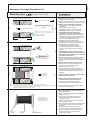
1
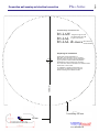
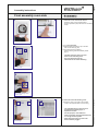
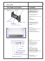
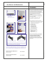
for integration in ventilation concepts according to DIN 1946 - Part 6
measured according to DIN EN 20140-10 (ehem. DIN 52210)
measured according to EN ISO 717-1; Prüfstand nach EN ISO 140-1
safety note
For your safety, please read before starting to use your ventilation unit
the information specified carefully. You get it important
Instructions for the proper use and maintenance of your new Room fan.
Ventomaxx-International is not liable if the following instructions are not followed
ECO COMFORT Plus
mounting instructions
User manual
Ventomaxx - International GmbH
Herzog Georg Platz 4 84028 Landshut www.ventomaxx - International.de
Subject to technical modifications 01.2015 © Ventomaxx - International GmbH
Tested in accordance with the principles of sound recognized by the building inspection
in consultation with the NABau UA DIN 4109 Supplement 1 00.71.02.
Vent maxx
The decentralized
Humid rooms ventilation
Page 2
ECO COMFORT Plus
safety instructions (Page 2)
mounting instructions (Page 3 - 6)
Page 3
Page 4
Page 5
Page 6
General installation requirements
Mounting template to prepare the wall opening
Assembly of the Rough construction-ring module set, Mounting Type LAW, straight through the wall
Mounting the Rough construction ring Module Set Mounting Type LAL, concealed within the soffit
electrical installation
Page 7
Page 8
Page 9
Page 10
(Page 7-10)
Final assembly room side - Electrical connection
Final assembly room side / group settings
Insert filter / close unit
Sets the operating function
User manual
Page 11
Page 12
Page 13
Page 14
Page 15
Page 16/18
(Page 11-18)
warranty
Device configuration / control panel
program functions
status reports
Units care / filter change
Commissioning protocol / service / customer services
safety instructions
Attention!
Protect it from wetness and moisture!
Before opening, disconnect the appliance from the mains!
All persons who have to do with the installation, commissioning and maintenance of the unit must be qualified.
This manual must be followed exactly! Probably missing documents we will send you on request at short notice.
First check the perfect condition of the package and the individual accessories. Pay attention to
the perfect condition of the power cord and the current-carrying wire to the fan unit. It is absolutely
ensure that no kinks and damage are present in it.
The device can be connected directly to the mains supply. When the mains plug design of the device must only
be connected to power outlets whose voltage and frequency with the nameplate of the unit exactly
The cable entries on / in Do not strain by pulling! There must always be out sufficient cable to the device.
Otherwise, the cable may be damaged, which can lead to a fatal electric shock.
When cleaning or revision of the device that needs to be taken out of operation; more dirt in and at the device
should only be removed by a professional; the circuit must be interrupted to all poles.
The cleaning of the room-side cover must only be carried out with a damp cloth.
The penetration of water or other liquids enter the device must be avoided. If this should
should happen, immediately disconnect the power by unplugging the power cord or turn off
the device fuse. Do not turn the power back on and secure it so that no unauthorized
Can be carried out commissioning.
Vent maxx
The ECO COMFORT Plus is an exhaust fan, equipped with a highly efficient sound insulation.
The ECO COMFORT Plus rounds so that the device series of sound-insulated supply and exhaust air devices,
with and without heat recovery off. The ECO COMFORT Plus is mainly designed for comfortable ventilation of
odor and moisture contaminated living rooms. Please make sure that the air inlet is open and not covered by any
objects. A liability for other use can not be accepted. To avoid moisture damage or human health impair, be
absolutely sure that a sufficient ventilation is guaranteed. Depending on the room use are supportive window
ventilation (eg push ventilation one the day) in addition to the planned ventilation concept required (eg in the
same room as the other Ventomaxx ventilation units).
For proper operation of the decentralized ventilation system is shutoff the availability requires of existing
combustion air lines.
Except changing the filter / equipment cleaning, no further maintenance is required. Please consult before any
Filter change the power plug or switch off the unit without power by turning off the fuse.
If the unit does not function properly, you should contact a qualified technician for.
mounting instructions
General installation requirements
ECO COMFORT Plus Ventilation devices can be in all standard constructions easy to fit and close when
installed inside and outside nearly flush.
The system has a modular design, allowing the use of equipment already been in the construction phase in the
desired mounting design (eg LAW, straight through the wall; LAL, concealed within the soffit) can be prepared.
The ECO COMFORT Plus can to a trouble-free AC power with 85-260V, 50/60 Hz are securely connected
(default). The device is also available with a 1.5 meters or 3 meters cable for connecting the Power outlet (S1.5
/ S3.0).
Please note:
For insertion of the fan within the wall apertures to the outside are on-site manufacture in accordance with the
following description. The required wall opening is to be provided with diameter of 200 mm. These installation
instructions describe the installation of the fan part in a monolithic exterior wall. Please determine which wall
structure is present and only use specified by the manufacturer fasteners for the wall.
Dependent on its condition the wall, different regulations / safety precautions must be observed (eg with an
asbestos-containing facade, etc).
The assembly is therefore in principle be carried out by specialist companies. If you are not sure which Gewerk
for the installation of the question or what tools and resources for professional installation is required, please
contact us!
During the execution of all work with machinery and equipment, the instructions of the machine supplier /
equipment manufacturer must be observed. All work must be performed with the recommended protective
clothing (eg, mouth, eye protection, gloves, etc.)!
When choosing your installation situation, note the following:
At the drilling no supply lines must pass;
For multi-layered construction is to make sure that the pierced vapor barrier is sealed according to the
manufacturer's instructions; in weather- acted upon areas is on the outside of the fan to provide a weather
protection (sh. to also provide information on each mounting).
The room side arrangement of the housing must be chosen so that the accessibility to the revision of the device
is always possible. The air exit on the unit must remain free in the range of about 25-30 cm long and must not
be obstructed by furniture or handicapped etc..
Page 3
ECO COMFORT Plus
Plus-Series
Available Rough construction sets
RS-LAW
RS-LAL
RS-LAL db-maxx
straight through the wall
concealed within the soffit
in right or left version
with maximum
sound insulation
Preparing for installation
Please note that the preparation of
May differ rough opening in terms of optimal
diameter and in way of the opening preparation
(eg in exposed concrete;Wood stud partitions;
Rehabilitation walls). Please this if necessary.
Your consult for technical clarification in individual cases
130 mm
Please note in this context
our installation / operating instructions and
in particular, the differences in the required
electrical cabling to the different series!
Core drilling 200 mm
65 mm
Page 4
Preparation wall opening and electrical connection
Page 5
Mounting of the rough-Ring Module Set
Mounting Type L AW
Comments
(straight through the wall)
Cross Section
Illustration of Solid Wall + Insulation System
Inside
Outside
RS-LAW
Slide roughing-Ring Module Set
Plaster Cover
Adjustment of the Total Length
Arrange Low Voltage
Installation Line 2x2x0.6
Wandstärke
e
esiv
ling
Adh
Plaster Cover
b) by adjusting the ring module sets the
Wall thickness, are still present connection
wall thickness the connection joints have to be
sealed diffusion resistantwith VX-FK
c) at LAW-assembly is a slope of Rough
construction-ring module sets plan at 1,5-3°
decline of your telescope unit from inside to
outside
4. Insulate bigger opening or hollow spaces
additionally with mineral wool professionally
5. Framed fixing in the wall with two component
polyurethane foam VX-2K
a) seal room-sided opening gap between wall and
channel diffusion resistant and permanently
elastic (Ventomaxx Installation Sealing Adhesive
VX-FK)
6. Protecting the Ventilation Unit from Dirt
a) therefore use the included protective cover
during the whole construction phase
(plaster cover of RS-LAW)
3° Decline
Achieve 1,5 to
ly Wedge
mb
se
As
via EPS
sound insulated -0030SP
00
Order-No.: 95
Outside
Air setback flap
(LRK) optional
LRK-DO Dn 100
Z-1000-0111
b) in order to avoid any kind of damage to the
ventilator during the construction phase, store
them in a well- protected place until the final
assembly
Install Façade
Covering and
Interior Housing
Inside
Outside
Inside
Sea
1. Creation of the wall opening
a) Opening 200 mm or square H / B 200 x 190 mm
establish or prepare in shell
b) prepare an empty tube or place a low voltage installation line 2x2x0,6 to the central control unit!
2. Making overall length with ring modules
(wall thickness incl. insulation system and
Plastering)
The ring module set is for use in
Wall thicknesses from 300 mm designed;
CAUTION: reduction only on the outside!
3. Ring Module Set slide into the wall,
adjusting it and fixing it without tension
a) depending on the desired place for the interior
cover (air outlet on top or bottom), the electric
cable has to be installed like the pattern shows
you (the standard air outlet is on top)
7. Install Façade Cover after the completion of
plaster and painting works
8. Install interior housing right before the
completion of the construction phase
a) fix the room- sided housing right on the
intended fixing points of the telescope unit
Please note Mounting instructions for facade cover!
b) to avoid deformations on the housing tighten
screws gently and uniformly
9. Electronic Installation must be carried out
by a professional!
a) before you start working always pull the plug or
switch off the flush
The figure shows
this ECO COMFORT Plus
mounting version LAW,
straight through the wall
facade cover
FA-LAW-K
Ring modul-Set
RS-LAW
Unit
ECO COMFORT Plus
b) connect up to 6 ventilation devices to the
central control unit using the attached
connection scheme
c) initiate the devices via the central control unit
following the instruction
d) after completion of the electronic installation clip
the electronic protection cover and hinge the
front panel
e) the device is now ready for operation in
accordance with the operating instructions
f) further specialties should be cleared project
based early enough; we kindly offer you
support after a request
Monting Instruction ECO COMFORT Plus - Monting type LAW
In the lower part is an on-site seal between Rough construction ring Module Set
and base plate facade cover required (eg aluminum adhesive tape; Ventomaxx sealing adhesive VX-FK);
at the top of the hood and sides of a seal on the facade is necessary.
Page 6
Mounting of the rough-Ring Module Set
Mounting type L A L
Comments
(concealed within the soffit)
section vertical
representation Solid wall + insulation system
Slide the fan Unit
Inside
RS-LAL
installation cable
Provide NYM-J 3x1.5
view from the side
Outside
Plaster Cover
Adjust fan nominal length
Socket junction having
duct tape
seal all around
Wall Thickness
section vertical
e
esiv
ling
Adh
Achieve 1,5 to
3° Decline
Inside
Outside
Plaster Cover
Sea
mbly Wedge
via EPS Asse
sound insulated -0030SP
00
Order-No.: 95
1. Creation of the wall opening
a) Opening 200 mm or square H / B 200 x 190 mm
establish or prepare in shell.
b) prepare an empty tube or place a low voltage installation line 2x2x0,6 to the central control unit!
2. Making overall length with ring modules
(wall thickness incl. insulation system and
Plastering)
The ring module set is for use in
Wall thicknesses from 330 mm designed;
CAUTION: reduction only on the outside!
3. Ring Module Set slide into the wall,
adjusting it and fixing it without tension
a) depending on the desired place for the interior
cover (air outlet on top or bottom), the electric
cable has to be installed like the pattern shows
you (the standard air outlet is on top)
b) by adjusting the ring module sets the
Wall thickness, are still present connection
wall thickness the connection joints have to be
sealed diffusion resistantwith VX-FK
c) at LAW-assembly is a slope of Rough
construction-ring module sets plan at 1,5-3°
decline of your telescope unit from inside to
outside, for flat channel is 5 ° (degrees)
d) Flat duct flush on the outside Soffit level
adjust; Shorten if necessary; by matching
Fix flat duct holder on the outside wall
4. Insulate bigger opening or hollow spaces
additionally with mineral wool professionally
5. Framed fixing in the wall with two component
polyurethane foam
Flat-channels in "dB-maxx-execution" are towards with> = 20 mm mineral wool to insulate the exterior wall.
For plaster facades we recommend a flat Channel insulation of 30 mm.
Air setback flap
(LRK) optional
LRK-DO Dn 100
Z-1000-0111
Outside
Install Façade
Covering and
Interior Housing
Inside
section vertical
a) seal room-sided opening gap between wall and
channel diffusion resistant and permanently
elastic (Ventomaxx Installation Sealing Adhesive
VX-FK)
6. Flat duct system within the covering
insulation level
a) the adjustable Soffit connection embeddable
for later plaster level of Soffit corner
adjusted / taping all around
b) Interface between flat duct, insulation
flat and plaster connection with illmod tape
seal
7. Protecting the Ventilation Unit from Dirt
b) so that the system support unit with fan
during the construction phase not be damaged,
should these to final assembly of a
protected area is temporarily stored.
Ring modul-Set
RS-LAL
The figure shows
the ECO COMFORT Plus
Mounted version LAL,
for concealed integration
inside the soffit
8. Install Façade Cover after the completion of
plaster and painting works
9. Install Façade Cover after the completion of
plaster and painting works
a) fix the room- sided housing right on the
intended fixing points of the telescope unit
use plaster cover RS-LAL for flat duct.
b) to avoid deformations on the housing tighten
screws gently and uniformly
Flat duct holder
FKH
façade connection
with integrated condensate drain
Unit
ECO COMFORT Plus
Façade Covering
FA-LAx 37
10. electrical connection
a) Before starting work, switch off the fuse /
Pull out the plug! Further steps as in
Mounting Type LAW; see also the following
pages
Monting Instruction ECO COMFORT Plus - Monting type LAL
a) this is the included, room-side protection
cover during the construction phase
to use; In addition, we recommend the use
set the VX-LAL-plaster cover for the flat channel
Installation instructions / electrical installation
the sound ahead.
Final assembly room side
Comments
4. Slide system unit into the wall
5
a) den von der Platine kommenden Stecker
(links unten am raumseitigen Plus-Gehäuse)
nach unten legen um Platz für den Einschub
zu schaffen
b) Als Erstes die Ventilatoreinheit in das Rohr
einschieben (bis kurz vor Rohrende)
fig. similar
fig. similar
4.b
R
Page 7
VENTOsonic
c) danach ggf. zugehörige Schalldämmelemente einsetzen.
Low-voltage connection between
Fan and circuit board
Fan unit push in the
wall
6.a
5. Lüfteranschluss
a) Der Niedervolt-Lüfter (24V Gleichspannung)
wird über eine Schnellsteckverbindung mit
der Platine verbunden (sh. weißen Kreis)
b) das von der Platine kommende NiedervoltRundkabel in die rechte Kabelkerbe
am Gehäuse eindrücken
c) das Gerät ist nun in den Werkseinstellungen betriebsbereit
6.b
6. Geräte mit internem HYGRO (Option)
Die Geräte sind nach wie vor stromlos!
6.c
a) Die Steckverbindung für das HYGRO-Modul
befindet sich links unten an der Platine
b) Stecken Sie das Hygro-Modul auf die Platine
c) Der Hygro-Sensor zeigt dabei in Richtung
der Fühler-Öffnung im Plus-Gehäuse
d) Stellen Sie jetzt bitte den gewünschten,
Feuchte-Richtwert gemäß Tabelle links
unten ein.
Abb. ähnlich
fig. similar
6.d
DIP-Schalter setzen und
max. Feuchte-Sollwerte
gemäß nebenstehender
Übersicht festlegen.
12 3 4
ON
7. HYGRO-Funktionen (Option)
40%
ON
circuit boards
connections
OFF
50%
OFF
OFF
60%
ON
ON
ON
L1
N
70%
OFF
80%
ON
flat ribbon
connection
membrane
keyboard
+
PWM
potential-free contact
-
setting
Hygro-desired values
Monting Instruction ECO COMFORT Plus - Monting type LAL
Setpoints for internal HYGRO
make in DIP switch
OFF
Die Wahlmöglichkeiten hierzu erfahren Sie
weiter hinten unter „Programmfunktionen“
DIP-Switch
4-polig
Assembly instructions / electrical installation
the sound ahead.
Final assembly room side
Comments
R
Page 8
VENTOsonic
Preparation of the room sided housing
a) Press the unlocking device at the housing and
lift the front design cover
b) Remove the inserted isolation
c) Set the screw driver like shown in the
illustration and snap the electronic cover
with soft pressure
Press the unlocking
device here
Set the
screwdriver
here
1. Disconnect the power supply from current
a) reduce connection cable for Landline connection
and wire stripping; it is only the phase and the
Neutral needed
b) case of mains plug version unit is not in the
Plug Power outlet
1
connecting cable
NYM-J 3.15
2. Monting of the room- sided housing
Wall telescope unit and
Grid connection are prepared
b) connect the housing and telescope
unit by fastening the screws at the
intended fixing points.
2.b
fig. similar
2
a) pull the low voltage line through the
opening of the device on the backside.
2.b
2.a
clamping range
for cable connections
unlocking
housing cover
Screws
3.9 x 13-16
3. Electrical connection
The unit has an international
Wide range input
3.a
fig. similar
3
U: 90 - 260 V
f: 50 / 60 Hz
N
L1
Kabelanschluss:
A: 0,75 - 1,6 mm 2
a) The connection of the fan is controlled by
the green terminal block with N and L1
b) alternatively, the unit is already be provided
with plug-in connector from factory
3.a
Connector internally. Hygro-Sensor
Clamp the voltage
connection
Potential free contact
In terminal block 2-pole, green
The power supply of the device via a
Ring line provided with its own fuse.
Monting Instruction ECO COMFORT Plus - Monting type LAL
Design-Casing at the
Wall / screw it to the RS
Assembly instructions
the sound.ahead .
Final assembly room side
Comments
7
7.a
R
Page 9
VENTOsonic
7. Close the cover of electrical devices
Hook the cover on the housing bottom
and the separation pad press until he noticeably
snaps
Close electric cover
8
8 - 11 Put in the Filter
a) Slide the filter frame at the top of the two
filter connections (fig. 8a)
b) Then filter frame by pressing
Clip the latching hook successively below
(fig. 9)
8.a
The filter change is done in reverse
Order on the unlocking of the
two clips and removal of the
Filter frame at the central fastening.
Put in the Filter
9
10
10.a
10. Place the room-side housing cover
a) Hook the cover in the area of the roll and
snap on the opposite side on the housing
The ventilation devices can now as to
described the following page, in
Operation are taken
For this purpose, units with fixed
mains connection, through switch the fuse
on and get electrical power
Hang the unit cover
and click tight
Units with power plug can now in the
Power outlet be plugged
Monting Instruction ECO COMFORT Plus - Monting type LAL
Filter in both latching hooks
left lock / right
Page 10
ECO COMFORT Plus
Operating Guidelines
General Operating Instructions / Warranty
The ECO COMFORT Plus you have a high-quality energy-efficient ventilation unit
decided which was designed for continuous operation. In the event that you ever want to take the
warranty service, please contact with the dealer, from whom you purchased the product.
Please read the instructions carefully before order to exclude that the error was not caused by
incorrect adjustment or operation.
All Ventomaxx products are subject to the implied warranty of two years. It contains material and production
defects. The warranty starts with the date on which the product was purchased respectively installed. You
have to submit the evidence for the purchase or the installation. For this we ask you for a voucher a receipt
where the dates can be found in. Ventomaxx reserves the right to reject the warranty if the evidence for the
purchase and/or installation is not provided.
In the case of a justified warranty defect, which is due to a lack of materials or faulty manufacturing,
Ventomaxx will either repair the product, Replace defective parts or replace the product.
The warranty is excluded for the following cases if:
- the assembly and operating guidelines have been ignored
- the assembly/ installation was carried out wrong
- the device was improper handled/ willfully or deliberately damaged or destroyed
- intervention(s) on the device were not carried out by expert staff
- components are affected that are exposed to normal, foreseeable stress
- No original spare parts are used
Caution
Do not remove the cover of the electrical part yourself in order to avoid a the risk of an electric shock. There
are no parts behind the cover of the electrical part and the base plate that need to be maintained by the
customer. Please let expert staff carry out electrical interventions.
Cleaning and Care
Filter Exchange
In order to guarantee a consistent quality of fresh air, please check the condition of the filter and the
components that conduct air flow regularly. Please exchange the filter at least once a year.
User Manual - ECO COMFORT Plus
The housing towards the room side respectively the room- sided cover is easiest to clean with a humid cloth.
In order to avoid damages of the surface only use water and a little detergent. Always make sure that no
water can ingress.
Page 11
User manual
Unit Design / control panel
Facade close
for Mounting Type LAW,
straight through the wall
Comments
Rough construction
Ring Module Set
mounting Type LAW
Adjustable
Air guide roller
The adjacent figure shows the
Unit Design for mounting type LAW,
straight through the wall.
Operate other types of mounting
this series is done the same.
All functions in ECO COMFORT Plus
can be carried out on site.
There are three buttons for the user operation
available..
- On / Off
- Program selection
- Choice of fan speed
Concealed integrated
panel
automatic air
Flap trap, optional:
Typ: LRK-DO Dn100
Art-Nr: Z-1000-0111 filter cartridge
The LEDs indicate only the current
Program state and the selected
Air power stage and the due date for
Filter change (see also page 14
LED display)
Initial start-up
The unit is named after the connection to the
Current network (fixed or plug)
immediately ready for use..
Always make sure that the device
is operated with an open air guide roller!
ON / OFF
When you press the button, the station is
on or off.
The unit starts to operate of
preset program function in which
preselected power stage on.
After restarting the device goes
to the last active mode.
Status
Fan Stages
On / Off
Fan Stages / Speed
Program selection and
Filter replacement
Unlocking the appliance control panel
Humidity sensor (optional)
To set the desired air flow rate
There are 10 levels. the stages
be by pressing the "Speed button"
forwarded. The respective stage
signaled by the corresponding LED.
About the luminous intensity of the Speed LED
two power levels are displayed.
Program selection
The program selection is on the
page following described.
User Manual - ECO COMFORT Plus
System support unit
with sound absorbing
Page 12
User Manual
Program functions
Comments
There are 4 programs to choose from
Programm
“Speed”
Unit on
1. permanent ventilation
The ventilation unit operates continuously on the
preset ventilation level (eg for ventilation
concepts with sound-proof external air diffusers
Series Air-Control)
The left Program LED will illuminate.
Prog. 1
2. Moisture protection "static"
(Option)
Demand air (with internal hygrometer
Sensor, optional). Once the preset
Humidity is achieved, start of exhaust air
operation on the selected fan speed until the
RH is 10% lower than the preset humidity setpoint.
Prog. 2
Prog. 3
The clamping of an external sensor (hygrometer,
Thermostat, CO2 sensor, etc.) allows the
Exhaust-operation on the selected by the user
to the ventilation unit power level.
Both program LEDs are off.
3. Moisture protection "dynamic" (Option)
How before, however, the air starts only when
the pre-set humidity level within the last 10
minutes to more than 10% RH rises above the
predetermined maximum value. It runs this unit
3 levels above the selected fan speed, and on
when the "set humidity" to the specified
user-ventilation level back. The unit will now
continue at this level until the RH to about 10%
below the humidity setpoint.
Both program LEDs are on.
4. pulse ventilation
The EcoComfort Plus runs every 6 hours for
15 minutes for the selected fan speed
The rights program LEDs are on
Prog. 4
The clamping a external sensor on the
potential free contact the circuit board allows
needs-based external fan control
at the preset power level.
The optional internal hygro sensor is in this case
automatically disabled.
Prog. 2
Both program LEDs are off.
User Manual - ECO COMFORT Plus
external control
Page 13
User Manual
Status-Message
Comments
Filter change indicator
A filter change is required after about 4000 hours
of operation.
In this case, the flashing of the LEDs indicates
the program impending filter changes.
flash
of LED
selected
stagee
Unit on
Carried out reset the filter change status
directly by RESET at the Unit
For this purpose press the program button
until the flashing is extinguished.
„Sleep-Modus“ LED-display
Uninstall
The uninstall of the module is performed by the specialist.
On effect at the time of disposal standards and guidelines must be observed.
When changing the mounting situations or when using optional
accessories deviations are possible in the effective air power.
User Manual - ECO COMFORT Plus
As soon as you no more entries on the
control panel makes , the LEDs after a short time
off; as soon as you the described press any key,
the current selected parameter reappears
(LED light up again).
Page 14
User Manual / Unit Maintanance
Comments
1
Only a clean air handling unit is a guarantee for
a hygienic air exchange. Because the operating
environment and device run times can differ
from case to case, we recommend that you
clean the filter and the system supporting unit in
the first months of use once more as
recommended below, to check for proper
condition.
Thus, the filter change is not overlooked, your
Ventomaxx ventilation unit is equipped with a
filter change indicator.
2
Press release of the
housing cover;
Remove the front cover
The ventilation unit otherwise no other
maintenance is required by the user.
Filter on the two tabs
Unlock and remove
3
4
Put the filter in pickup device
Clip the behind both tabs
Hang the casing cover
and lock
Filter replacement is performed as follows:
a) Remove the front cover on the unit; to middle
unlocking on the housing pressures; Cover
by tightening unhook (Figure 1)
b) The filter frame is
two retaining clips in
held device housing;
by pressing the tabs
the filter frame can at
central web without tools
be removed (Figure 2)
c) New filter in the reverse
Sequence in the housing
Insert; Front cover
Hook and up to
Slightly click press down.
Please note that depending on the location of
the object to change the filter approximately
every 6-8 months may be required. An
examination of the filter for possible
contamination should be done regularly.
Regardless of the degree of pollution filter for
hygienic reasons, must be replaced at least
once a year.
Section Mounting Type LAW
Section Mounting Type LAL
When replacing the filter system supporting unit should be removed
and be checked for contamination. It lends itself to it, at the same
time units inside dust Suck out and wipe damp.
Replacement filter AIRstatic G3
Article-Number
1500-1903VX
Allergic-replacement filter F6
Article-Number
1500-1906VX
User Manual - ECO COMFORT Plus
Ventomaxx replacement filter for the ECO COMFORT Plus
You can obtain under the following article number from us:
Page 15
Technical Data
Eco Comfort Plus
Series / device design
Exhaust air unit soundproofed
Eco Comfort Plus
Control
internal / on the device
3
Performance is based on 5 steps further
5 levels can be selected as an intermediate stage
~ 15 / 30 / 45 / 55 / 70
Permanent operation at the preset ventilation stage
Permanent Ventilation
Air capacity 10-stage, in m /h
Program function
linke Programm-LED leuchtet
Needs-based exhaust air in combination with optional internal hygro sensor
or external switch actuator (eg. Hygro / thermostat, CO2 sensor, etc.)
Moisture protection stat.
both Program-LEDs are off
Needs-based exhaust air in combination with optional internal hygro sensor with auto.
Priority switching with rapidly rising humidity (eg after bathing or showering)
Moisture protection dyn.
both Program-LEDs are on
pulse ventilation
every 6 hours for 15 minutes on the selected fan speed
right Program-LEDs iluminated
Content protected by copyright - Subject to technical changes
Fan type
EC, radial, digital
Fan Stage 1 bis 5
(Stage max. ca. 9,5 Watt)
Fan power consumption
ca. 1 - 1,8 Watt
Supply voltage (control), at 50/60 Hz
90-260 Volt - AC
Operating voltage (Unit)
230V AC / 24V DC
electricity connection
Fixed line / power plug
optional
Fan Stage 1 bis 5
(Stage max ca. 41 dB(A))
Sound pressure level / relaxation room suitable **
sound insulation (from outside noise)*** depending on device type
Filter quality
Norm sound level
difference
F5/F6 optional
similar
RAL 9003
Cover Room side
Housing Dimensions HxWxD
nominal length
48 - 60 dB, Dnew
G3
ABS white
ca. 280x218x55 mm
conform to the system made of stainless steel or
Aluminum with condensate drain
Facade close
~ 17 - 27 dB
(with optional add-on module VLE 150)
modularly expandable
shortened on site
Weight
optional, Color on choice
380 mm
ca. 3-4 kg
www.ventomaxx-International.de
01-2015
The right rough opening (about 185-200 mm) is a project basis (round or square) set
so that this is always covered sufficiently by the selected units aperture during the
final assembly. We will gladly provide you with the necessary dimensional drawings
on request.
**Surface sound pressure level Lpf
***measured according to EN 140-10 / EN ISO 140-2 / EN ISO 717; in accordance with test certificate ift-Rosenheim
... the sound ahead.
Your local contractor
Ventomaxx-International GmbH i.G.
Herzog Georg platz 4
84028 Landshut
Phone: +49 2361 499450
[email protected]
Eco Comfort Plus
Vent maxx