1
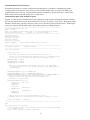
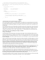
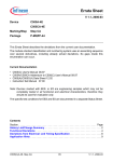
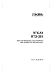
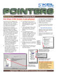
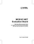
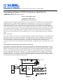
C COMPILERS • REAL-TIME OS • SIMULATORS • EDUCATION • EVALUATION BOARDS
Programming the Siemens C167CR CAN interface: A Real Life Case
Application Note 115 - Short Version
By Gary Culp and Robert Boys
Keil Software, Dallas, Texas.
1-800-348-8051 or [email protected]
This application note demonstrates programming the on-chip CAN interface of the Siemens C167CR microcontroller
using the Keil C166 C Compiler and two Keil MCB167 evaluation boards. You can get a low cost CAN network
running quickly with these tools. Some unusual aspects of programming the CAN module discovered during the
project development are provided. Keil provides the sample source code as well as the full version of this application
note on the website www.keil.com/~market. You can compile and run this code with the free evaluation version of the
C166 Compiler and monitor dScope. (www.keil.com/products.htm). Modification of this code will enable it to run on
the C505C or the C515C using the Keil C8051 Compiler. These parts are 8 bit 8051 based CAN microcontrollers.
The full version of this document is known as Application Note # 115 and contains the details needed to complete the
project.
CAN - An overview
The CAN (Controller Area Network) is a serial bus originally developed for use in automobiles. It is finding additional
applications in other areas such as factory automation. The physical layer is usually a differential twisted wire pair.
The message with the highest priority gets through. This application note assumes some familiarity with CAN and its
associated terminology. Introductory documents on CAN can be accessed through links on the Keil web site
(www.keil.com/can). These are also available on the Keil CD ROM. Call (800) 345-8051 or [email protected] for a free
copy.
The Keil MCB167 Evaluation Board & the Siemens C167CR chip
Some variants of Siemens microcontrollers have an on-chip CAN interface. These are the C505C and C515C (8051
based) and the C167CR and C164CI (16 bit). Siemens also makes the SAE 81C90 and 91 peripheral chips. The Keil
MCB167 evaluation board contains a C167CR operating with 0 wait states, 256K static RAM and associated support
circuitry. It can support up to 2 M RAM and 1 M ROM. Addition of a simple physical layer IC such as the Philips
82C250, completes the CAN interface. See Figure 1. The MCB167 supports the Keil C Compiler, Assembler and
Target Monitor dScope. You can write, compile and run/debug programs of up to 4 K with the free Keil C Compiler
and dScope debugger. These programs can be executed and debugged in either using the software debugger (dScope)
or in the MCB167 target board using the monitor option.
+5V
P4.6
C1
10µF
16V
P4.5
P4
3
22k
J1
1
2
Slope Control
A
8
U1
PCA82C250
Philips
7
6
C
B
SW1-7
R1 120
C167CR
4
5
1
7
2
6
SW1-8
Figure 1
CAN
Bus
Keil FR166 RTOS and CAN Libraries
Keil Software produces two versions of a Real Time Operating System. The FR166 is a multitasking real-time
operating system for the Siemens 166/167 family. You can manage multiple tasks on a single CPU making your
programs much easier to develop. The RTX166 Full includes CAN libraries. The RTX166 Tiny is a subset of the
RTX166 Full and is included with all Keil 166 C Compiler Kits.
Functional Description of the Example Programs
Program A_CANX1 keeps a transmit message object updated; the CAN controller automatically transmits it without
any CPU intervention when a remote frame requesting it is received. See Figure 2 for the source. Program B_CANX1
transmits a remote frame requesting a message, waits to receive the message, then repeats the process. Each program
runs on one of the two Keil MCB167 boards. Recall these programs are available from Keil.
/******************************************************************************
C167CR CAN Application Note 119
Main - a_canx1
This is an example program showing how to use the CAN interface on the Keil
MCB167 evaluation board.
Copyright (c) 1997 Keil Software
******************************************************************************/
#include <stdio.h>
#include <intrins.h>
#include "can_ifc.h"
#include "timer.h"
#include "can_msgs.h"
#define TIME_MO 1 /* message object number for time message */
/******************************************************************************
Setup CAN controller
Returns: nothing
-----------------------------------------------------------------------------*/
void setup_can(void)
{
begin_can_init();
/* These mask values tell the CAN controller that all bits in a
message id. are significant when comparing the id of a received message
to the id's in the arbitration registers of the message objects.
*/
CAN_MASK_SHORT = 0xffff;
CAN_UMASK_LONG = 0xffff;
CAN_LMASK_LONG = 0xf8ff;
/* Since this program doesn't use message object 15, it is unnecessary
to initialize the 'mask of last message' registers (CAN_UMASK_LAST and
CAN_LMASK_LAST).
*/
CAN_MSGOBJ[TIME_MO].msg_ctl = MSGVAL_CLR;
CAN_MSGOBJ[TIME_MO].arbitr = ARBITR(CAN_TIME_MSG);
CAN_MSGOBJ[TIME_MO].msg_cfg = MSG_CFG(LEN_CAN_TIME_MSG, CANDIR_TRANSMIT, 0);
/* We're not initializing the data field right now, so we set
CPUUPD to prevent the message from being transmitted in
response to a remote frame.
*/
CAN_MSGOBJ[TIME_MO].msg_ctl =
/* clear bits
set bits */
INTPND_CLR &
RXIE_CLR &
TXIE_CLR &
MSGVAL_SET &
NEWDAT_CLR &
CPUUPD_SET &
TXRQ_CLR &
RMTPND_CLR;
/* CAN_IE_ must be set for any CAN interrupts to occur.
CAN_EIE_ must be set for CAN error status change interrupts to occur.
*/
end_can_init(CAN_IE_ | CAN_EIE_);
}
/******************************************************************************
main
This program does the following:
Set up the CAN controller, with a message object for the time stamp message
as a transmit object.
Setup a timer to generate periodic interrupts.
2
Loop forever, periodically updating the time stamp message object.
The CAN controller will transmit the time stamp message when it receives a
remote frame for it, without any intervention from the CPU. Returns: never
-----------------------------------------------------------------------------*/
void main(void)
{
printf("Program A start\n");
/* Set up */
setup_can();
init_timer();
/* set up CAN interface */
/* initialize timing */
/* Run */
while (1) {
/* infinite loop */
unsigned long t;
t = timer();
update_can_transmit_message(TIME_MO, &t, LEN_CAN_TIME_MSG);
/* Put the processor in idle mode to conserve power.
The next interrupt (from the timer) will wake it up again.
*/
_idle_();
}
}
Figure 2
A Brief Description of the C167CR On-chip CAN Interface
The C167CR on-chip CAN interface is an XBUS peripheral. The XBUS is the on-chip manifestation of the external
bus. XBUS peripherals look like external devices to the software and have the same characteristics as external devices.
Since the processor's bit addressing capabilities do not apply to external devices; registers of the CAN module are not
bit-addressable.
The CAN module interfaces to the CPU through several general registers and 15 message objects. Most of the general
registers affect the overall operation of the CAN module and are located from 00’EF00H to 00’EF0FH. Each message
object consists of 15 bytes of registers located from 00’EF10H to 00’EFFEH. Message objects 1 through 14 can be
configured as either transmit or receive objects. Message object 15 is a double-buffered receive-only message object.
Some Unusual Aspects of Programming the On-chip CAN Module:
Message Control Registers
One of the registers in each message object is the message control register. These contain flags which are set and
cleared in a rather unusual way. Each flag is represented by a pair of bits. When the register is read, the value of each
bit pair will be either 01, meaning the flag is clear (i.e. false), or 10, meaning the flag is set (i.e. true). When writing to
the register, these same values may be written to the bit pair to set or clear the flag, or 11 may be written to the bit pair
to leave it unchanged.
There is a good reason for this unusual design. Because the on-chip CAN interface is an XBUS peripheral, it is not bitaddressable. The CPU must access its registers as whole bytes or words. When the CPU needs to change just some of
the bits in a register it can read the register, change the necessary bits, and write the modified value back to the register.
In the case of the message control registers of the message objects, this approach would cause a problem: the CAN
controller may change some of the bits between the time the CPU reads the register and the time the CPU writes the
modified value back. The CAN controller's changes to the register would be lost, even when the bits changed by the
CAN controller are among the bits the CPU was not trying to change.
The example programs in this application note use a collection of preprocessor macros for computing the value to write
to a message control register to set, clear, and leave unchanged any combination of flags. Each of these macros
compiles to a 16-bit unsigned constant in which all but one of the bit pairs is 11. The remaining bit pair is 01 in the
x_CLR macros, or 10 in the x_SET macros. These macros are defined in the file canregs.h.
To change several flags at one time, combine the corresponding macros using the bitwise-AND operator, '&'. For
example, writing CPUUPD_CLR & TXRQ_SET to a message control register simultaneously clears the CPUUPD flag
and sets the TXRQ flag, while leaving the other flags unchanged. Don't combine the x_SET and x_CLR macros for
the same flag, because that would produce the illegal value 00 for that flag's bit pair.
The CPUUPD and MSGLST flags are actually the same bit pair, but the meaning of that bit pair is different depending
on whether the message object is a transmit object (CPUUPD) or a receive object (MSGLST).
3
MSGVAL flag
Every message object must be initialized for the CAN module to work properly. For unused message objects, it is
sufficient to mark the object as invalid by clearing the MSGVAL flag in the object's message control register. The
CAN controller ignores invalid objects. When the CPU needs to change the message identifier for a message object, it
should mark the object invalid by clearing the MSGVAL flag in the message control register, make the changes, then
mark the object valid again by setting MSGVAL.
When the CPU merely needs to update the data for a transmit message object, the message should not be marked
invalid. If a remote frame for the message were received while the message object is invalid, it would be ignored; the
node that sent the remote frame would never get the data it asked for. A different procedure for updating data in a
message object is explained below.
Concurrency control for message objects
Since the CPU and the CAN controller can access the message objects concurrently, their activities must be coordinated
to avoid garbling messages.
1. Concurrency control for transmit objects
It might seem that if the CPU started updating a message while that message were being transmitted, the transmitted
message could be partly the old version and partly the new version. But the CAN controller contains a shift register into
which the entire message is loaded at once when it is to be transmitted. Therefore, even if the CPU changes the data in
the message object while the message is being transmitted, the CAN controller, working from the shift register,
transmits the original version of the message. If the CPU follows the recommended update procedure (explained later),
the CAN controller will then, separately, transmit the updated version of the message as well.
A similar problem could occur if the CAN controller started transmitting a message while the CPU was in the midst of
updating it. To prevent this problem, the CPU must set the CPUUPD flag in the message control register before
starting to change the data. The CAN controller will not start transmitting a message while its CPUUPD flag is set.
When a remote frame for the message is received, the CAN controller sets the TXRQ and RMTPND flags. This
happens even if the CPUUPD flag is set when the remote frame is received. The CAN controller remembers the
request for transmission and will honor it after the CPUUPD flag is cleared.
The proper procedure for updating the data in a CAN transmit message object follows. The function
update_can_transmit_message in the source file can_ifc.c does this
1)
2)
3)
Set CPUUPD and NEWDAT.
Copy the new data into the data area of the message object.
Clear CPUUPD.
2. Concurrency control for receive objects
Receive objects also present potential concurrency problems. If the CAN controller receives a message while the CPU
is still processing a previous version of the message, the CPU could process a message that is partly the old message
and partly the new message, leading to incorrect results.
The CAN module does not provide any way of holding off reception of new messages until after the CPU has processed
them. It does, however, set the NEWDAT flag for a receive message object each time it updates the message object
with a new received message. If the CPU uses the following procedure, it can avoid processing mixed messages:
1)
2)
3)
4)
Clear the NEWDAT flag
Copy the data from the message object to a buffer in memory.
If the NEWDAT flag is set, go back to step 1.
Process the copy of the received message.
It might seem that this could cause an infinite loop, but since the CPU can perform this procedure in a small fraction of
the time it takes for even the fastest CAN message to be received, it does not. It is probable that in most real-world
systems, the data would never have to be copied more than twice. The function copy_received_can_message in
can_ifc.c implements this procedure.
Postponing Initialization of Data in Transmit Objects
In the example program a_canx1 it is more convenient to set up a transmit object as part of the initialization of the
system but to postpone placing real data in the data field and allowing the regular update process to do that. The initial
set-up of the message object should leave the CPUUPD flag set to prevent the message from being transmitted before it
contains real data.
4
Multiple Reception
A node on a CAN bus can receive multiple copies of a message when it expects only one.
One reason for this is hinted at above: if the CPU updates a message while it is being transmitted, the CAN controller
will finish sending the old version of the message, then send the new version. This causes two different versions of the
message to be received. Both of them are consistent and correct, one is just newer than the other.
Another cause can lead to identical copies of a message being received. A CAN transmitter decides that a message has
been successfully passed a little later than a CAN receiver does. It is possible for something to happen in between, so
that the receiver treats the message reception as successful and passes it on to its CPU, but the transmitter treats the
attempt as a failure and retransmits the message.
You must design your systems to cope with this multiple reception. One of two simple approaches will usually deal
with this phenomenon. Which to use depends on the nature of the data. It may be necessary to use both in the same
program, for different messages.
The first approach is to just use the most recently received message and forget about the earlier one. This would
probably be the approach to use for something like an engine temperature reading.
The second approach is to include a serial number as part of the message data. The CPU in the transmitting node gives
incrementing serial numbers to successive messages. The receiving CPU compares the serial number in a newly
received message to the serial number of the previously received copy of the message. If they are the same, it ignores
the newly received message. This scheme is suitable when a stream or large block of data are to be sent via a series of
messages with the same message id.
The serial number can be as short as 1 bit. By using the mask registers, or by using two different message objects, it
might be possible to incorporate the serial number into the message identifier, leaving all eight bytes of the message
data field for data. The software for such a scheme would be more complicated than for one incorporating the serial
number in the data field.
Copying Data to and from Message Objects
The eight bytes of message data registers in the message registers start at an odd address. All word (16-bit) accesses by
the C167 must be on even addresses. It is therefore not possible to copy the data to and from the message objects as
four words. In these example programs, the data are copied one byte at a time. A mixture of byte and word transfers
could be written in assembly language which would be slightly faster than copying one byte at a time, but it hardly
seems worth the trouble.
Busoff Error Recovery
Recovery from infrequent errors is handled automatically by the CAN module. Very frequent errors put the device into
a state called busoff. Recovery from busoff is also handled by the CAN controller, but it requires CPU intervention to
start the process.
Once a CAN node has gone into the busoff state, it is not allowed to attempt to communicate on the CAN bus until it
has completed the busoff recovery procedure. This must be explicitly initiated by software. The busoff recovery
procedure consists of monitoring the CAN bus until 128 sequences of 11 consecutive recessive bits have been observed.
A recessive bit is one that can be changed by a dominant bit. This is the mechanism used to make sure the highest
priority message gets through. Each successful transmission on the CAN bus ends with 11 recessive bits and the idle
state of the CAN bus contains recessive bits. Therefore, when the CAN module sees 128 sequences of successive
recessive bits, it indicates some combination of normal bus activity and an idle bus. The CAN controller will assume
that the bus is working normally.
In the C167CR, the CAN module sets the BOFF and INIT bits in its control/status register when a busoff condition
occurs. The CPU can tell the CAN module to begin the busoff recovery procedure by clearing the INIT bit. When
busoff recovery is complete, the CAN module will clear the BOFF bit. If error interrupts are enabled (the EIE and IE
bits in the CAN control/status register are set), any change in the BOFF bit will generate an interrupt. In the example
programs, the CAN interrupt handler function can_interrupt in the source file can_ifc.c contains all the code for busoff
recovery.
The CPU can track the progress of the bus off recovery, but doing so would be pointless in many (probably most)
applications. If you need this capability, read about CAN interrupt handling and the CAN control/status register
(especially the SIE bit and LEC field) in the user's manual for the processor.
5
Conclusion
This article illustrates both the complexity and ease of implementing the CAN bus into your project. Once you
comprehend the basic concepts of the CAN Module, you will find that it does most of the CAN communications work
for you. The Keil tool chain facilitates the development of your CAN project. Combined with the Keil RTOS and the
CAN libraries, powerful projects can be written , compiled, and debugged efficiently.
16990 Dallas Parkway • Suite 120 • Dallas, Texas • 75248 • 800-348-8051
6