1
ICPAGING
Application User Manual
ICPAGING intercom and paging system
ICPAGING ABCL FW version
VA1.10
Doc. release version
31.01.2013
ICMASTER
V01.09
ICCLIENT
V01.07
ICGRAPH Master HD configuration
V1.0
ICGRAPH Master FD configuration
V1.0
© 2013 Barix AG, all rights reserved. All information is
subject to change without notice. All mentioned
trademarks belong to their respective owners and are
used for reference only.
REVISION TABLE
Date
Version
Who
Change
09/07/12 Draft
AD
First draft.
10.07.12 Draft
SG
Added ICgraph chapter
28.08.12 001
AD
Updated for IcPaging 1.05
30.08.12 002
AD
Updated for IcPaging 1.06
10.09.12 003
AD
Updated for IcPaging 1.07
28.09.12 004
AD
Updated for IcPaging 1.08
25.10.12 005
AD
Updated for IcPaging 1.09
31.01.13 006
AD
Updated for IcPaging 1.10
Table of Contents
1
Introduction......................................................................................7
1.1
About “ICPAGING”............................................................... 7
BARIX AG | 2/91
1.2
Features................................................................................ 8
1.3
Supported hardware.......................................................... 10
1.4
Additional documents........................................................ 12
1.5
ICPAGING ABCL Firmware................................................ 12
1.6
1.6.1
1.6.2
1.6.3
About this manual.............................................................. 12
Links to chapters................................................................ 12
Bookmarks pane in Adobe Acrobat.................................. 13
Chapter overview............................................................... 13
2
Running ICMASTER.......................................................................15
2.1
Booting up PS16 ICMASTER............................................. 15
2.2
PS16 Keyboard Layout ..................................................... 16
2.3
Running ICMASTER on Annuncicom 100/200/PS1..........21
2.4
ICMASTER Web home page.............................................. 22
2.5
2.5.1
2.5.2
ICMASTER Web configuration pages............................... 23
BASIC SETTINGS............................................................... 23
ADVANCED SETTINGS...................................................... 26
2.5.2.1
2.5.2.2
2.5.2.3
2.5.2.4
2.5.2.5
2.5.2.6
2.5.2.7
Network..........................................................................................26
BARP Control.................................................................................29
Audio..............................................................................................31
Incoming Call.................................................................................33
Paging............................................................................................34
I/O Control......................................................................................35
Security..........................................................................................35
3
Running ICCLIENT.........................................................................38
3.1
About ICCLIENT................................................................. 38
3.2
Available keys..................................................................... 38
3.3
ICCLIENT Web home page................................................ 39
3.4
3.4.1
3.4.2
ICCLIENT Web configuration page................................... 40
BASIC SETTINGS............................................................... 40
ADVANCED SETTINGS...................................................... 42
BARIX AG | 3/91
3.4.2.1
3.4.2.2
3.4.2.3
3.4.2.4
3.4.2.5
3.4.2.6
3.4.2.7
3.4.2.8
Network..........................................................................................42
BARP Control.................................................................................43
Audio..............................................................................................44
Outgoing Call.................................................................................47
Background Music........................................................................48
Serial..............................................................................................50
I/O Control......................................................................................51
Security..........................................................................................52
4
Running ICgraph............................................................................53
4.1
About ICgraph.................................................................... 53
4.2
How to run ICgraph............................................................ 53
4.3
4.3.1
Usage of ICgraph............................................................... 54
Intercom functionality with ICgraph.................................. 57
5
Implementing example paging system.........................................59
5.1
Necessary components..................................................... 59
5.2
System layout..................................................................... 59
5.3
5.3.1
5.3.2
5.3.3
Configuring the master station.......................................... 61
Initial setup......................................................................... 61
General settings................................................................. 62
ICMASTER settings............................................................ 63
5.4
5.4.1
5.4.2
5.4.3
Configuring the door station.............................................. 65
Initial setup......................................................................... 65
General settings................................................................. 65
Door station settings.......................................................... 65
5.5
5.5.1
5.5.2
5.5.3
Configuring the cash desk station..................................... 66
Initial setup......................................................................... 66
General settings................................................................. 66
Cash desk settings............................................................. 67
5.6
5.6.1
5.6.2
5.6.3
Configuring the stereo music player................................. 67
Initial setup......................................................................... 67
General settings................................................................. 67
BGM player settings.......................................................... 68
BARIX AG | 4/91
5.6.4
Connecting the Volume Source Control (VSC) unit..........68
5.7
5.7.1
5.7.2
Configuring the PC for BGM distribution.......................... 69
Hardware requirements..................................................... 69
Configuring the MP3_RTP_Streamer................................ 69
5.8
5.8.1
5.8.2
5.8.3
5.8.4
5.8.5
Testing the Paging system................................................ 71
Recording a custom message........................................... 71
Rejecting a call................................................................... 72
Answer a call...................................................................... 72
Paging................................................................................. 72
Paging the custom message............................................. 72
6
Additional information...................................................................74
6.1
Updating a device using the RS-232 serial port ..............74
6.2
Restoring Factory Defaults of PS16 ................................. 75
6.3
6.3.1
6.3.2
6.3.3
Configuring ICPAGING in multimaster environment.........76
Call Failover scenario:........................................................ 76
Call all masters scenario.................................................... 77
Call all + failover scenario:................................................. 77
6.4
Understanding BARP address bitmaps............................ 77
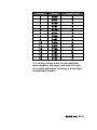
6.5
BIN / DEC / HEX conversion.............................................. 79
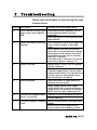
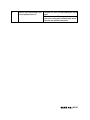
7
Troubleshooting.............................................................................81
8
Dictionary.......................................................................................83
8.1.1
8.1.2
8.1.3
8.1.4
8.1.5
8.1.6
8.1.7
8.1.8
8.1.9
DHCP ................................................................................. 83
FDX .................................................................................... 83
HDX .................................................................................... 83
IP ........................................................................................ 83
IPzator ............................................................................... 84
MAC address...................................................................... 84
Netmask.............................................................................. 84
Static IP.............................................................................. 85
VSC..................................................................................... 85
BARIX AG | 5/91
8.1.10
8.1.11
8.1.12
8.1.13
8.1.14
8.1.15
8.1.16
8.1.17
8.1.18
8.1.19
8.1.20
IP Addressing..................................................................... 85
Class A network................................................................. 86
Class B network................................................................. 86
Class C network................................................................. 86
Class D network................................................................. 87
Class E network................................................................. 87
Network Address................................................................ 87
Broadcast Address............................................................ 87
IP Netmask......................................................................... 88
Private IP Networks and the Internet................................ 89
Network RFC’s................................................................... 89
9
Legal Information...........................................................................90
BARIX AG | 6/91
1
1.1
Introduction
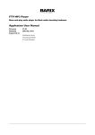
About “ICPAGING ”
ICPAGING is a fully functional solution for
building intercom and paging systems over IPbased networks. With ICPAGING, BARIX
devices can be easily configured and become
part of the paging system in few minutes.
Being designed with a master/client
architecture, the ICPAGING application can be
configured to run either as a master (called
ICMASTER), or as client (called ICCLIENT). The
communication between the master and the
client components of the paging system is
implemented using the Barix IP protocol
(BARP).
The ICMASTER station can control the
ICCLIENT's mode of operation, send broadcast
paging messages to any or all of them, and
activate their relays to drive different
peripherals. Multiple masters can coexist and
be configured within a system.
Also the in the package contained ICgraph
software (Java based PC software) can be
used as ICMASTER system/station.
The ICCLIENT stations are typically used as
door intercom stations or paging stations with
background music playback. They can also be
configured to initiate an intercom connection
with up to two master stations.
BARIX AG | 7/91
1.2
Features
System:
• master / slave architecture
• BARP compatible: integrates seamlessly
with other BARP applications like
MP3_RTP_Streamer, ICGRAPH, BARP
paging client
• priority based audio messaging
• easy WEB based configuration
• multiple master configuration – “call all
masters” and “call failover” scenarios
ICMASTER
• full or halfduplex mode of operation
• handsfree mode for sending paging
messages and half-duplex communication
• up to 112 available keys (with two 48 keys
extensions)
• configurable audio messages priority
• intercom (client call master)
• caller ID display
• configurable ringtones per client
• till 8 configurable single or group target
buttons
• paging up to 128 devices
• 1 dynamic group
• configurable unattended mode timeout
• configurable call reject mode (for
BARIX AG | 8/91
multimaster environment)
• recordable unattended mode message
• recordable custom message
• control of local and clients volume
• client background music (BGM) channel
control
• 10/100 Mbit Ethernet connection supports
automatic network configuration (BOOTP,
DHCP, IPzator, and as well as manual static
IP configuration
ICCLIENT
• full or half duplex mode of operation
• single or multimaster mode
• playing paging messages
• intercom to master
• supports the HAI Volume Source Control unit
and IR remote control
• background music (BGM) playback and
control
• background music playback in mp3 format
• AIPHONE door panels support
• 10/100 Mbit Ethernet connection supports
automatic network configuration (BOOTP,
DHCP, IPzator, and as well as manual static
IP configuration
ICGraph PC software
• full or half duplex for Intercom mode
BARIX AG | 9/91
• single or multimaster mode
• playing paging messages
• remote switching of client relay
1.3
Supported hardware
The ICPAGING solution is designed to run on
the following Barix devices:
•
PS16 Paging Station – while it is possible
to use the PS16 as a client, with its 112
available keys (16 available, others on
separate 48 keys extension(s), and two line
LCD display is the perfect device to be run
as an ICMASTER station.
•
Annuncicom 200 – can be used as a
master or as a client. Provides mono BGM,
intercom, door relay control and paging
endpoint functionality. When used as a
client, the available two wire interface
allows the device to use the
AIPHONE
door stations in half-duplex mode.
•
Annuncicom 100 – can be used as a
master or as a client. Provides mono BGM,
intercom, door relay control and paging
endpoint functionality.
•
Exstreamer 100, 105 – used as client.
Provides stereo BGM and paging
endpoint functionality.
•
Exstreamer P5 – used as client. Provides
mono BGM and paging endpoint
functionality combined with 5W amplified
speaker output and Volume Source
BARIX AG | 10/91
Control (VSC) port.
•
Exstreamer 110,120 - used as client.
Provides stereo BGM, door relay control
and paging endpoint functionality. In
addition, it has 2 lines LCD display and an
IR port for remote control1.
•
Exstreamer 200,205 - used as client.
Provides stereo BGM and paging
endpoint functionality. In addition, it has
2x25 W amplified speaker output and an IR
port for remote control.
•
Annuncicom PS1 – this device can be used
as a client or as a two buttons master,
allowing to answer incoming intercom call
requests and to page a predefined group
of targets (Group key 1 Address Map from
the web configuration page).
•
Annuncicom 60 – used as a client.
NOTE: other Barix devices not in this list may or
“may not” work correctly with ICPAGING
application.
NOTE: when Annuncicom PS1 is used as a
master, all features using the USB stick are
disabled (i.e. customized station ringtones,
unattended mode, recording unattended and
custom messages).
1
The built in IR receiver of Exstreamer 110/200 is not accessible from BCL.
ABCL applications (like ICPAGING) can use the BARIX external IR dongle, or
the IR receiver of the Volume Source Control unit.
BARIX AG | 11/91
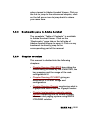
1.4
Additional documents
Technical specifications for the supported
devices can be found in the corresponding
product sheet which can be downloaded from
our site www.barix.com.
The ICPAGING System has been developed in
BCL and is distributed with its source code
enabling users to further customize it if they
wish to. For detailed technical information
about the programming language please
download the “Barix Control Language (BCL)
Programmers Manual” from our website.
1.5
ICPAGING ABCL Firmware
Barix provides the ICPAGING solution as a
prebuilt ABCL package containing the
ICMASTER and ICCLIENT applications. The
ICMASTER and ICCLIENT are guaranteed to
work only when they are from the same ABCL
ICPAGING package. Using ICMASTER and
ICCLIENT from ICPAGING packages with
different versions may not work correctly, since
new functionality are continually being
developed.
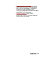
1.6
1.6.1
About this manual
Links to chapters
References to chapters (e.g. X Chapter name)
are red and underlined and serve as direct links
BARIX AG | 12/91
when viewed in Adobe Acrobat Viewer. Click on
the link to jump to the referenced chapter, click
on the left arrow icon to jump back to where
you came from.
1.6.2
Bookmarks pane in Adobe Acrobat
The complete “Table of Contents” is available
in Adobe Acrobat Viewer. Click on the
“Bookmarks” pane tab on the left side of
Adobe Acrobat Viewer to open it. Click on any
bookmark to directly jump to the
corresponding part of the manual.
1.6.3
Chapter overview
This manual is divided into the following
chapters:
• Chapter Running ICMASTER describing the
functionality provided by the ICMASTER, the
key mapping and the usage of the web
configuration UI
• Chapter Running ICCLIENT giving an
overview of ICCLIENT usage and
configuration
• Chapter Running ICgraph mentioning what is
ICgraph and how to use the ICgraph master.
• Chapter Implementing example paging
system explaining how to create a simple
intercom and paging system using BARIX
ICPAGING solution
BARIX AG | 13/91
• Chapter Additional information explaining
how to rescue a device via the serial port,
how to use the ICPAGING in multimaster
environment, and providing a quick
reference to BARP address bitmap handling
and BIN/DEC/HEX conversion.
• Chapter Dictionary giving a short
explanation of some of the most important
terms used in this manual.
BARIX AG | 14/91
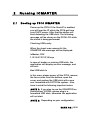
2
2.1
Running ICMASTER
Booting up PS16 ICMASTER
Power up the PS16. If the SonicIP is enabled,
you will hear the IP which the PS16 got from
your DHCP server. After that the device will
start detecting the USB stick. The following
message will be shown on the PS16 LCD while
the check is being performed:
Checking USB sanity
When the check was successful, the
ICMASTER idle message will be displayed:
IcMaster, FDX
1.02 04.07.2012,16 keys
In case of broken or missing USB stick, the
application will display an error message, and
will exit:
Bad USB stick fs
In this case, please power off the PS16, remove
the two screws from the bottom, open the
cover, and replace the USB stick with a new
one, formatted with FAT32 file system. Also,
have in mind the following important notes:
NOTE 1: If you plan to use the ICMASTER on
Annuncicom 100/200, please plug in a
formatted USB stick, otherwise the application
will not start.
NOTE 2: Depending on your configuration,
BARIX AG | 15/91
the following files may be present on your USB
stick:
–
UNATTSND – this is the recorded
unattended mode message;
–
CUSTMSG – this is the recorded custom
message;
–
TEST.USB – an empty temporary file
created during USB stick check;
–
xxx.MP3 – station ID specific ring tone
files, where xxx is the station ID (for
example 002.mp3 is the ring tone for
station ID=2).
None of them is required for the application to
boot, but it is advised to backup these files
(without the TEST.USB as it will be deleted and
recreated during boot) and copy them to the
new USB stick to keep the same configuration.
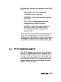
2.2
PS16 Keyboard Layout
The PS16 Paging main unit has 16 functional
buttons, a flexible microphone, speaker, and 2
line LCD. Optional extensions with 48 keys can
be attached on the right side of the PS16 main
unit. Key layout for PS16, as well as for every
master device, is shown in the web UI home
page, as in Illustration 1:
BARIX AG | 16/91
Illustration 1: ICMASTER keyboard layout
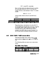
If a PS16 extension is connected, key 17(bottom left corner) to key 64 (top right) are
assigned respectively to targets 17 to 64.
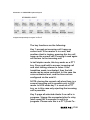
The key functions are the following:
Key 1: accept an incoming call / hang-up
current call. If the master is in a call, and
another client is ringing, pressing this key will
hang-up the current call. Pressing it once again
will answer to the incoming call.
In half duplex mode, this key works as a PTT
key. Press and hold to answer incoming call
and start talking, release to listen. If the
handsfree mode is activated, then the talk
mode can be voice controlled. In this case the
voice activation level, and the time-out are
configured via the web UI.
NOTE: closing the current call when there is a
second incoming call is possible only in FDX
mode. In HDX mode key 1 is used as a PTT
key, so in this case only rejecting the incoming
call is possible.
Key 2: page all selected clients if no call is in
progress / trigger the connected client's relay
(door open) for 5 seconds if a call is in
progress. Please note this is a PTT (Push-ToBARIX AG | 17/91
Talk) button when the handsfree mode is not
activated. In handsfree mode, press this key
once to activate the paging mode, and once
again to stop it. The key LED blinks when
paging is active.
Key 3: pressing this key will cancel an incoming
call (either in idle mode, or when the
ICMASTER is in a call session with one client,
and another client is calling). If the ICMASTER
is in a call and there is no other incoming call,
pressing this key will also hang-up the current
call session.
Key 4: clear current target/group selection.
Key 5: enter unattended mode, (pressing any
other key exits unattended mode). Clients that
try to call a master that is in unattended mode
will have the 'unattended message' played to
them and the call will be terminated once the
message has been played.
Pressing and holding this key for 4 seconds will
enter the master in “call reject mode”. When
the master is in this mode, and a client calls in,
instead of opening a call session and sending
the unattended message, it will send a special
message to the client informing that it is not
available. In this case the client should call the
next master in its list.
NOTE: if the ICMASTER does not
cancel/answer the second call, the ICCLIENT
will continue ringing and hang-up automatically
after a certain amount of time (configurable via
the ICCLIENT web UI).
NOTE: when the unattended mode is disabled
from the web UI, pressing this key puts the
BARIX AG | 18/91
master immediately in call reject mode.
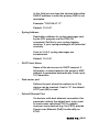
Key 6: when pressed allows to listen the
unattended message locally.
Key 7: when pressed without any selection
allows to listen the custom message locally.
When there are targets selected, the custom
message is sent to the selected destination/s.
Key 8: record custom or unattended message.
Press and hold this key together with key 6 to
record unattended message or with key 7 to
record custom message. Recording stops
when this button is released.
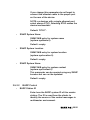
Key 9: select page group 1. The address
bitmap assigned to this key is configured from
the related ICMASTER web UI address map
configuration page.
Key 10: select page group 2. The address
bitmap assigned to this key is configured from
the related ICMASTER web UI address map
configuration page.
Key 11: select page group 3. The address
bitmap assigned to this key is configured from
the related ICMASTER web UI address map
configuration page.
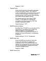
Key 12: select page group 4. The address
bitmap assigned to this key is configured from
the related ICMASTER web UI address map
configuration page.
Key 13: select page group 5. The address
bitmap assigned to this key is configured from
the related ICMASTER web UI address map
configuration page.
BARIX AG | 19/91
Key 14: select page group 6. The address
bitmap assigned to this key is configured from
the related ICMASTER web UI address map
configuration page.
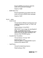
Key 15: select page group 7. The address
bitmap assigned to this key is configured from
the related ICMASTER web UI address map
configuration page.
Key 16: select page group 8. The address
bitmap assigned to this key is configured from
the related ICMASTER web UI address map
configuration page.
Keys 17-112: select client ID (17-112) .
Important note !!!
When the ICMASTER is run in HDX mode,
pressing key 1 when there is an active call will
not close it. In HDX mode, key 1 is used as PTT
(Push-To-Talk) key. When pressed, the
microphone of the ICMASTER is switched ON,
the speaker turned OFF, while the mic of the
ICCLIENT is automatically switched OFF, and
its speaker turned ON.
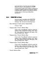
2.3 Running ICMASTER on Annuncicom
100/200/PS1
The ICMASTER can be used also on the
Annuncicom 100/200 and PS1 devices with
limited functionality. Because on these devices
there are only two available keys, the key
mapping is a bit different than the one
BARIX AG | 20/91
described for the PS16:
Full duplex (FDX) mode:
Key I: answer incoming/Close current call.
Key2: if it is in a call, pressing this key will open
the relay on the client for 5 seconds. When the
ICMASTER is in idle mode, pressing key 2 will
start paging to Group 1.
Half duplex (HDX) mode:
Key 1: answer incoming call. While the call is
active, it works as a PTT key – press and hold
to talk, release to listen.
Key2: if it is in a call, pressing this key will open
the relay on the client for 5 seconds. When the
ICMASTER is in idle mode, pressing key 2 will
start paging to Group 1
Press and hold key 1, then press key 2: Close
the current call.
In addition, as the PS1 device does not have
USB port, all features that use it are disabled
(customized station ring-tones, unattended
mode and custom messages recording).
BARIX AG | 21/91
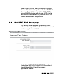
2.4
ICMASTER Web home page
Illustration 2: ICMASTER home page
The device home page is dynamically autorefreshed every second and shows some useful
run-time application details.
Under the “APPLICATION STATUS” section is
visible the BARP station ID and the current
application status.
Under the “AUDIO LEVELS” section input and
output audio levels are displayed, in dB.
The section “KEYBOARD LAYOUT” shows the
layout of the keys, as supported and used in
the current hardware.
BARIX AG | 22/91
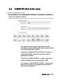
2.5
ICMASTER Web configuration pages
The configuration of the ICMASTER is very
intuitive and easily done via the web UI.
Example snapshots of the basic settings and
advanced settings pages are shown on
Illustration 3 and Illustration 7.
2.5.1
BASIC SETTINGS
The BASIC SETTINGS page is accessible
clicking the CONFIGURATION button in the top
menu, it shows the most important options to
be set up for a quick configuration.
Illustration 3: ICMASTER basic settings page
BARIX AG | 23/91
•
BARP Station ID
Enter here the BARP system ID of this master
station. The ID is used from the clients to
identify the source of the control messages in
multimaster environment.
Default is “1001”.
•
Duplex Mode
Choose the desired mode of operation.
Default setting is "Full".
•
Hands Free
When set to yes, and HDX mode is enabled, the
talk/listen mode can be voice controlled. In
Intercom mode, if the voice level exceeds the
one set in "Input Trigger Level", the master is
switching in talk mode, and the client in listen
mode. In Page mode, the Page key needs to be
pressed once (instead of press and hold) to
activate the paging, and pressed again to stop.
Default setting is "No".
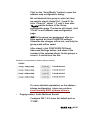
Hands Free Keys
The function of the keys changes, depending
upon the device and the configuration (Full/Half
duplex):
BARIX AG | 24/91
Function
FD Key
HD Key
Accept Call (IC)
1
1
Reject Call (IC)
3
3
Close Call (IC)
1 or 3
3
Open Relay (IC)
2
2
Start Paging
2 (blinks whilst Paging)
Stop Paging
2
PS16
PS1 and other 2 button Annuncicoms
•
Accept Call (IC)
A(1)
A(1)
Close Call (IC)
A(1)
A(1)+B(2)
Open Relay (IC)
B(2)
B(2)
Start Paging
B(2)
Stop Paging
B(2)
Group 1 Address Map
Allows to set up the first group (1) of
destination targets. Click related “View/Modify”
button to setup the group. A label on the right
shows the number of selected clients in this
group.
Default setting is "id’s 1 to 10 selected".
BARIX AG | 25/91
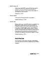
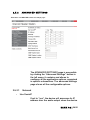
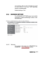
2.5.2
ADVANCED SETTINGS
Illustration 4: ICMASTER advanced settings page
The ADVANCED SETTINGS page is accessible
by clicking the “Advanced Settings” button in
the left menu, it contains and allows to
configure all the application options, organized
in specific subsections. The advanced settings
page shows all the configurable options.
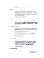
2.5.2.1
•
Network
Use SonicIP
If set to "yes", the device will announce its IP
address over the audio output when the device
BARIX AG | 26/91
boots up.
Default setting is: "yes”
•
IP Address
Enter the 4 values of the desired device IP
address e.g.: "0.0.0.0" for automatic discovery
(DHCP/Bootp, IPzator, AutoIP), or a specific IP
for an internal LAN.
Default value: "0.0.0.0"
•
Netmask
Enter the 4 values of the desired Static IP
e.g.:"0.0.0.0" for a default Netmask depending
on the used IP Address. "255.255.255.0" for a C
class network
•
Gateway IP Address
Enter the 4 values of the desired Gateway IP
address e.g.: "0.0.0.0" for no Gateway, or the
IP of the gateway in your LAN
Note: The Gateway has to be set only when
connecting to other devices over the WAN
(through a router).
Default: "0.0.0.0"
•
Primary DNS
In this field you can give the desired primary
and alternative DNS IP address to be able to
connect to URLs (e.g. www.radio.com).
Example: "195.186.1.111"
Default: "0.0.0.0"
•
Alternative DNS
BARIX AG | 27/91
In this field you can type the desired alternative
DNS IP address in case the primary DNS is not
reachable.
Example: "195.186.4.111"
Default: "0.0.0.0".
•
Syslog Address
Destination address for syslog messages sent
by the BCL program via the SYSLOG
command. Set this to your syslog logging
machine, if your syslog messages are recorded
centrally.
If set to 0.0.0.0, syslog messages are
broadcasted.
Default: "0.0.0.0".
•
DHCP Host Name
Name of the device sent in DHCP request. If
left empty, a name based on the device's MAC
address is generated automatically. Enter up to
15 Characters.
•
Web server port
Defines the port where the webserver of the
device can be reached. If set to "0" the default
HTTP port (80) is used.
•
Default Ethernet Port
On devices with dual-ethernet connection this
parameter selects the default port to be used.
In most cases selecting ETH1 is suitable,
however some devices (e.g. the PS16) provide
Power-over-Ethernet (PoE) functionality on
ETH2.
BARIX AG | 28/91
If you change this parameter do not forget to
connect the ethernet cable to the proper port
on the rear of the device.
NOTE: on devices with a single ethernet port
select always ETH1. Selecting ETH2 makes the
device inaccessible!
Default: "ETH1".
•
SNMP System Name
SNMP MIB entry for system name
(system.sysName.0).
Default : empty.
•
SNMP System Location
SNMP MIB entry for system location
(system.sysLocation.0).
Default : empty.
•
SNMP System Name
SNMP MIB entry for system contact
(system.sysContact.0)
This parameter can be queried using any SNMP
browser but can not be updated.
Default : empty.
2.5.2.2
•
BARP Control
BARP Station ID
Enter here the BARP system ID of this master
station. The ID is used from the clients to
identify the source of the control messages in
multimaster environment.
BARIX AG | 29/91
Default is “1001”.
•
Paging Priority
Enter here the priority of the audio messages
sent by this master station. This setting is
useful in multimaster environment when a client
receives audio messages from many masters
simultaneously. In this case the client will play
the stream with the highest priority.
The priority must be in the range [1-254].
Priority "0" (the highest) is reserved for
emergency priority port, priority "255" (the
lowest) is reserved for BGM.
Default setting is "127".
•
BARP Broadcast Address
By default the ICCLIENT uses a broadcast IP to
listen/send on the BARP ports. Modify the
BARP IP address to use multicast if
communication across different networks is
desired, or if your LAN policy is not allowing
broadcast.
Default setting is "0.0.0.0" (broadcast).
•
BARP Audio Port
Enter the BARP port number to which the
master will send audio for paging and
established calls. In the multicast port and
address are configured, this port will be used
only for incoming calls. Paging will be done
using the multicast group.
Default is "5555".
•
BARP Control Port
BARIX AG | 30/91
Enter the BARP port number to which the
master will send control messages.
Default is "5556".
•
BARP Status Port
Enter the destination port number where the
master will listen for BARP status messages.
Default is "5557".
2.5.2.3
•
Audio
Audio Format
Choose between different encoding types and
sampling frequencies ("µ-law" or "A-law" at 8
or 24 kHz).
Default setting is "µ-law 8 kHz".
IMPORTANT: If you change the encoding don't
forget to provide/record correct
unattended/custom audio message files! Also,
make sure to use the same encoding on ALL
devices of the ICPAGING system.
•
Acoustic Echo Cancellation
Choose between "On" and "Off".
Default setting is "Off".
Note: this options is visible/available only for
hardware that supports AEC.
•
Input Source
Choose the desired input source.
Default setting is "Mic".
BARIX AG | 31/91
•
Duplex Mode
Choose the desired mode of operation.
Default setting is "Full".
•
Hands Free
When set to yes, and Half-Duplex mode is
enabled, the talk/listen mode can be voice
controlled while the ICMASTER is in active
call. If the voice level exceeds the one set in
"Input Trigger Level", the master is switched in
talk mode, and the client in listen mode. The
behavior for paging is also changed: the Page
key needs to be pressed once (instead of press
and hold) to activate Paging mode, and
pressed again to stop.
Please see BASIC SETTINGS for keys to be
used in Hands-Free mode.
Default setting is "No".
•
Input Trigger Level
Triggering input audio level if "Hands Free"
mode is selected. Accepted range: 0-32767.
Default setting is "1000".
•
Inactivity timeout
Sending of the audio stream in “Hands Free”
mode stops after this number of milliseconds of
no input audio signal.
Default setting is "1000".
•
Microphone Gain
Microphone gain dB, increase if your
BARIX AG | 32/91
microphone is too faint, decrease if it's too loud
or overdriven.
Default: "21 dB".
•
A/D Amplifier Gain
A/D converter preamplification in dB. Increase
if the audio signal too faint, decrease if it's too
loud or overdriven. Default: "0 dB".
•
Default Volume
Choose between "0%" and "100%" in 5%
steps.
Default: "50%".
2.5.2.4
•
Incoming Call
Call Master by
Configures the way the master is being called.
If set to "ID" then the call is ignored if the
destination ID in the call request is not the
same as the one of the master. When set to "IP
Address", the master reacts on unicast, or
broadcasted call requests. The destination ID
check is ignored in this case.
Default is "IP address".
•
Unattended Mode
Enables or disables the unattended mode.
When enabled, the "Unattended Timer"
becomes visible, and can be configured.
Disabling the unattended mode is
recommended when using the master in a
multimaster environment because if any of the
masters is in unattended mode, it may always
BARIX AG | 33/91
pickup the incoming call thus preventing the
other masters to get the call. When disabled,
pressing the unattended mode key enters the
master in a "Call reject" mode
Default is "Enabled”.
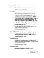
Unattended Timer
•
Configures the number of seconds after the
device switch to "unattended mode" during a
call. Minimum value allowed is 3, maximum is
60.
Default is "20".
2.5.2.5
•
Paging
Group Address Map
Allows to set up the related group of
destination targets. Click related “View/Modify”
button to setup the group. A label on the right
shows the number of selected clients in this
group.
Note: only available groups supported from the
current keyboard layout are displayed.
Default setting is: starting from group 1, 10
clients selected for every group, for group 1
id’s 1 to 10 are selected, group 2 id’s 11 to 20
selected … group 8 id’s 71 to 80 selected.
•
Audio Multicast Socket
Configures the multicast group socket, as
IP:PORT, for paging. As IP, it has to be within
the range 224.0.0.0 - 239.255.255.255. If set to
"0.0.0.0", then the default broadcast address is
used. Port is ignored if the IP is set to
BARIX AG | 34/91
"0.0.0.0" .
Default is "0.0.0.0:12345" - use broadcast.
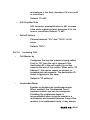
2.5.2.6
•
I/O Control
Relay 1 Control
Configures the relay behavior. The relay can be
either off ("always off"), on while an incoming
call is pending ("relay while ringing") or on while
a call is in process ("relay while talking").
Default is "always off".
•
LED Status
Configures the device front panel led behavior
for the devices that have a led panel.
Default is "Input State".
2.5.2.7
Security
•
Reset Function
Enable or disable the "Reset" function on the
Reset button and on the WEB UI. In order to
restart the device press the Reset button once.
Default: "enabled".
•
Factory Defaults
Enable or disable the "Factory Defaults"
function on the Reset button. In order to revert
all settings to factory defaults keep the Reset
button pressed until the red LED starts blinking
(approx. 10 seconds).
Default: "enabled"
BARIX AG | 35/91
•
Update Function
Enable or disable the WEB Update function of
the device. If the Update function is disabled,
the only way to update the firmware is to use
the serial rescue.
Default: "enabled"
•
Set Password
This is visible as long as no password is set.
Enter a password (up to 25 characters) and hit
the "Apply" button. After the restart you should
close the browser window and open a new
browser window. You will be asked to supply
user name and password. The user name can
be omitted but the password has to be
supplied in order to see the web configuration.
•
Old Password / New Password
These fields are visible as long as a password
is set.
To allow free access (clearing the password)
enter the old password and leave the field
"New Password" empty. Enter the old
password in the password field above the
"Apply" button as well and then hit the "Apply"
button.
After the restart you will not be asked for user
name and password anymore.
To change the password enter the old
password and enter the new password in the
field "New Password". Enter the old password
in the password field above the "Apply" button
as well and then hit the "Apply" button.
BARIX AG | 36/91
After the restart you will be asked for user
name and password. The user name can be
omitted but the new password has to be
supplied in order to see the web configuration.
BARIX AG | 37/91
3
3.1
Running ICCLIENT
About ICCLIENT
The ICCLIENT application has to be run on all
client endpoints from the ICPAGING system.
The ICCLIENT can play BGM and paging
messages, initiate a call session to two
preconfigured ICMASTER stations, and send
periodically its current status. Being the slave
component from the master/slave architecture,
the ICCLIENT does not have the possibility to
control other devices from the ICPAGING
system.
3.2
Available keys
The ICCLIENT application uses the Input 0 (key
1) and Input 1 (key 2) that are available on the
connector of the supported BARIX devices. The
mapping of the keys is the following:
Key 1: Call ICMASTER station 1. The id or IP of
the ICMASTER station is configured via the
ICCLIENT web configuration page.
Key 2: Call ICMASTER station 2. The id or IP of
the ICMASTER station is configured via the
ICCLIENT web configuration page.
If the ICCLIENT is configured to operate with
the AIPHONE door panels, then the hardware
inputs are ignored, and the key 1 press is
emulated by the firmware. The IP of the
ICMASTER station 1 is only used in this case.
BARIX AG | 38/91
Note: The ICCLIENT can use the HAI Volume
Source Control unit together with the BARIX IR
Remote Control. However, if the ICCLIENT is
run on BARIX device with its own LCD display
(ex. BARIX Exstreamer 110) then the VSC LCD
cannot be used and stays blank.
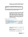
3.3
ICCLIENT Web home page
The device home page is dynamically autorefreshed every second and shows some useful
runtime application details.
Illustration 5: ICCLIENT home page
Under the “APPLICATION STATUS” section is
visible the station ID and the current
application status.
BARIX AG | 39/91
Under the “AUDIO LEVELS” section input and
output audio levels are displayed, in dB.
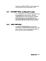
3.4
ICCLIENT Web configuration page
As in ICMASTER, the ICCLIENT application can
be configured in a fast fashion. Clicking
CONFIGURATION top menu button, a BASIC
SETTINGS page will be displayed. All the
application options are then available clicking
the ADVANCED SETTINGS left-menu button.
3.4.1
BASIC SETTINGS
The BASIC SETTINGS page is accessible
clicking the CONFIGURATION button in the top
menu, it shows the most important options to
be set up for a quick configuration.
BARIX AG | 40/91
Illustration 6: ICCLIENT Application “basic settings” Web Page
•
BARP Station ID
The system ID of this client station. The ID is
used to identify the unit at the master station.
Default setting is "1".
•
Duplex Mode
Choose the desired mode of operation. If “Half”
is selected, the communication is controlled
from the ICMASTER.
Default setting is "Full".
•
Use AI_Phone
This setting is for Annuncicom 200 hardware
only, which provides support for AI PHONE two
BARIX AG | 41/91
wire interface. Set to "Yes" if AI_Phone is used
as a door station. In this case “Half” operating
mode is recommended.
Default setting is "No".
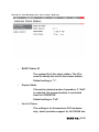
3.4.2
ADVANCED SETTINGS
The ADVANCED SETTINGS page is accessible
clicking the “Advanced Settings” button in the
left-side menu.
Illustration 7: ICCLIENT Application “advanced settings” Web Page
3.4.2.1
Network
This section is the same as in ICMASTER. See
ICMASTER 2.5.2.1 Network section.
BARIX AG | 42/91
3.4.2.2
•
BARP Control
BARP Station ID
The system ID of this client station. The ID is
used to identify the unit at the master station.
Default setting is "1".
•
BARP Broadcast Address
By default the ICCLIENT uses broadcast to
listen/send on the BARP ports. Modify the
BARP IP address to use multicast if
communication across different networks is
desired, or if your LAN policy is not allowing
broadcast.
Default setting is "0.0.0.0".
•
BARP Audio Port
Enter the BARP port number where the
ICCLIENT will listen for incoming audio.
Default setting is "5555".
•
BARP Control Port
Enter the BARP port number where the
ICCLIENT will listen for BARP control
messages.
Default setting is "5556".
•
BARP Status Port
Enter the destination port number to which the
ICCLIENT will broadcast BARP status
messages.
Default setting is "5557".
BARIX AG | 43/91
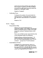
•
Notification Port
Enable here the usage of the notification port
which the client may listen for any incoming
audio. No BARP messages are checked for this
port, so any audio arriving at this port will be
played immediately. This can be used as a
"Broadcast to all" feature.
Default setting is "No".
3.4.2.3
•
Audio
Audio Format
Choose between different encoding types and
sampling frequencies ("µ-law" or "A-law" at 8
or 24 kHz).
Default setting is "µ-law 8 kHz".
IMPORTANT: make sure to use the same
encoding on ALL devices of the ICPAGING
system.
•
Acoustic Echo Cancellation
Choose between "On" and "Off".
Default setting is "Off".
Note: this options is visible/available only for
hardware that supports AEC.
•
Input Source
Choose the desired input source.
Default setting is "Mic".
•
Duplex Mode
Choose the desired mode of operation. If “Half”
BARIX AG | 44/91
is selected, the communication is controlled
from the ICMASTER.
Default setting is "Full".
•
Use AI_Phone
This setting is for Annuncicom 200 hardware
only, which provides support for AI PHONE two
wire interface. Set to "Yes" if AI_Phone is used
as a door station. In this case “Half” operating
mode is recommended.
Default setting is "No".
•
Microphone Gain
Microphone gain dB, increase if your
microphone signal is too faint, decrease if it's
too loud or overdriven.
Default: "21 dB".
•
A/D Amplifier Gain
A/D converter preamplification in dB. Use this
setting to achieve the right balance to your
connected equipment. Increase if the audio
signal too faint, decrease if it's too loud or
overdriven.
Default: "0 dB".
•
Default Paging Volume
The setting is the default volume used for
paging and intercom audio. Choose between
"0%" and "100%" in 5% steps.
Default: "50%".
•
Minimal Paging Volume
BARIX AG | 45/91
The setting is used as a minimal volume limit, in
case the volume is set from the paging source.
Choose between "0%" and "100%" in 5%
steps.
Default: "10%".
•
Maximal Paging Volume
The setting is used as a maximal volume limit,
in case the volume is set from the paging
source.
Note: a control volume of 0 (remote muting) is
anyway accepted.
Choose between "0%" and "100%" in 5%
steps.
Default: "90%".
•
Default BGM Volume
The setting is used as the default BGM volume
at device start-up. Choose between "0%" and
"100%" in 5% steps.
Default: "50%".
•
Minimal BGM Volume
The setting is active if HW Volume Source
Control is used. Choose between "0%" and
"100%" in 5% steps.
Default: "10%".
•
Maximal BGM Volume
The setting is active if HW Volume Source
Control is used. Choose between "0%" and
"100%" in 5% steps.
Default: "90%".
BARIX AG | 46/91
•
Notification Volume
Sets the default notification volume. In case a
notification message is received and the
paging volume is lower than notification
volume, notification volume is used.
Default: "90%".
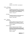
3.4.2.4
•
Outgoing Call
Call Masters by
Configures the way the master stations are
called. If set to "IP address", the masters are
called by unicasting the call request command
to the master IP. If set to "ID" then the masters
are called by broadcasting the call request
command with the destination ID=master ID.
Select the needed option so see the
corresponding configuration fields.
Default: "IP address".
•
Master Station ID
When “Call Master by BARP ID” is set, enter
the system ID of the related (1 to 4) master
station.
The first master station is called after pressing
the Button 1 (activating the first digital input).
Default setting is "for master stations 1 to 4,
respectively 1001,1002,1003,1004".
•
Master Station IP
When “Call Master by IP Address” is set, enter
the IP address of the related (1 to 4) master
station. If set to zero, uses broadcast to find a
BARIX AG | 47/91
master station on the local network.
The first master station is called after pressing
the Button 1 (activating the first digital input).
Default setting is "0.0.0.0".
•
Call next Master
If set to "Yes" the client is forced to call the
next master in the list if the one that it is
currently calling is not responding (for example
because of network problems or power failure
of the master). The call to the next master is
activated after the expiry if the auto hang-up
timeout. In this case the call ring timer is
restarted when the client starts calling the next
master.
Default: "No".
•
Auto Hang Up
Configures the number of seconds after which
the client will stop ringing if the master is not
responding. Minimum value allowed is 3,
maximum is 60. Make sure this value is greater
than the unattended mode timeout set for the
ICMASTER, otherwise the ICCLIENT will not get
the unattended message from the ICMASTER.
Default: "20".
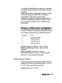
3.4.2.5
Background Music
Background Music multiple-channel service
(BGM) works listening for one or more UDP
audio streams on a range of ports. Stream
audio format expected must be as RTP MPEG.
BARIX AG | 48/91
To enable the BGM service almost a starting
port and a total number of channels must be
supplied.
Once the service is enabled, channels can be
switched using the Barix VSC accessory
connected to the device serial port.
In addition, once the service is enabled, for
devices supporting an HW line input, a local
line in channel (channel 0) is available and
selectable.
Example of BGM service configuration
This example shows how to setup the BGM
service to listen to multiple broadcast streams,
for a desired scenario as in the table below:
Channel
0
1
2
3
Desc.
Local Line Input
Audio Stream 1
Audio Stream 2
Audio Stream 3
BGM Broadcast Address : set to 0.0.0.0
BGM First Broadcast Port : set to 11001
(default)
BGM Available Channels : set to 3
BGM Start Channel : set to 1 (allows Audio
Stream 1 to be played at startup)
•
BGM Broadcast Address
Enter the broadcast/multicast address of the
background music streaming server. If set to
“0.0.0.0” then broadcast is used.
Default setting is "0.0.0.0".
BARIX AG | 49/91
•
BGM First Broadcast Port
Enter the broadcast/multicast port of the first
channel background music streaming server.
The BGM streaming could be provided by
multiple streamers, but they have to be
configured to use consecutive port numbers. If
set to "0", the BGM functionality is disabled.
Default setting is "11001".
•
BGM Available Channels
Enter the number of the available background
music channels. If set to "0" then BGM will be
disabled. If greater than "0", a local channel 0
will be available for local line input.
Default setting is "0".
•
BGM Start Channel
Enter the background music channel to start
playing after a reboot. If it more than the
available channels, then the last one will be
used.
Default setting is "0".
3.4.2.6
Serial
•
Serial Port
Selects the way the device serial port will be
used. Select “VSC Panel” here to use Barix
VSC accessory with this application.
Default: Intercom Client Software.
BARIX AG | 50/91
3.4.2.7
•
I/O Control
Relay 1 Control
Set here the default relay behaviour. Available
values are:
"always off" - the relay is off in all states
(idle,BGM playback,paging and intercom);
"on while in a call" - the relay is normally off,
but when the client is in intercom state, the
relay automatically switches on;
"always on, off while in a call" -this is the
inverted version of "On while in a call" setting.
The relay is normally switched on, and off when
the client is in a intercom state.
"on while in PA mode" - the relay is normally
off, but when the client is receiving paging
message, the relay automatically switches on.
"on while receiving audio stream" - the relay is
normally off, but when the client is receiving
audio stream (either in intercom, or PA mode),
the relay automatically switches on;
Note: Please have in mind that the BARP relay
control command is ignored when the relay is
not in "always off" mode in order not to
override the preconfigured relay behaviour.
Default: "always off".
•
LED Status
Configures the device front panel led behavior
for the devices that have a led panel.
BARIX AG | 51/91
Default is "Input State".
3.4.2.8
Security
This section is the same as in ICMASTER. See ICMASTER
2.5.2.7 Security section.
BARIX AG | 52/91
4
4.1
Running ICgraph
About ICgraph
ICgraph is a Java-based PC software. It
requires a Java Runtime Environment (JRE)
installed on the PC to run properly. Such JRE is
available for almost all operating systems (see
www.java.com ). ICgraph is a free Barix software
when used together with Barix hardware
products. This software is freely configurable
over the ICgraph.cfg file. It allows to control
ICPaging devices and communicate to it.
The ICPAGING firmware package contains two
different ICgraph configurations, one for halfduplex and one for full-duplex. These
configurations can be modified from you if
needed.
For more information about ICgraph check the
ICgraph manual available on www.BARIX.com .
4.2
How to run ICgraph
The ICPAGING software package contains a
sub folder “ICgraph Master”, there are two
different ICgraph configurations stored – one
for full-duplex and one for half-duplex.
Before you can start ICgraph, make sure the
Java JRE is installed (see www.java.com ) on
your PC.
If Java is installed, then decide which mode
BARIX AG | 53/91
(full-duplex or half-duplex) you will use for
Intercom communication with the clients and
select the according sub directory and start the
ICgraph.jar file from this directory.
ICgraph can be used as single master or
together with other Masters, but in multimaster
mode the behaviour is a little bit different than
using the ICMaster devices.
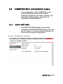
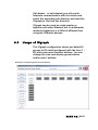
4.3
Usage of ICgraph
The ICgraph configuration shows per default 8
groups or 80 client (configured with Ids from 1 –
80) and some more function buttons. You can
change the view and display group buttons
and/or point buttons.
Illustration 8: ICgraph application (Full-duplex)
BARIX AG | 54/91
When ICPaging devices in the network are
properly configured then they will be
discovered after maximum 30 seconds from
ICgraph and the according point button will
change the color from dark grey to white. The
white point buttons can be used for other
actions on ICgraph. If a device is not more
reachable in the network (e.g. turned off or not
connected) then the point button will change
the color of this point button from white to dark
grey within 60 seconds.
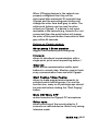
Buttons on ICgraph window:
Show group / Show member
toggles view between point and group
Intercom
allows bi-directional communication with a
single point, point must request/ring before !
Clear All
resets active communication and/or point
buttons to normal state. Must be used to finish
every communication from and with ICgraph.
Start Paging / Stop Paging
allows to make paging/announcements to
selected points and/or groups. For use this
function one, many or all points/groups should
be selected before clicking the “Start Paging”
button.
Mute ON/ Mute OFF
mutes/unmutes the ICgraph PC microphone
Relay open
allows switching of the remote relay for 3
seconds on selected device. Works only during
Intercom mode.
BARIX AG | 55/91
Menu OFF / Menu ON
displays or hides menu/buttons below this
button
Show events / Hide events
displays or hides event window, the event
window is a helpful tool which shows all current
point activities
Show LOG / Hide LOG
displays or hides LOG window, this window
displays all ICgraph activities, even the
background activities
Show records / Hide records
displays or hides Record window, this window
shows all recording you made with ICgraph or
from the sub folder “RECORDS”. From here
window select recordings or self-made audio
files can be sent to the selected devices.
Play message / Stop message
allows to stream a pre-recorded file to the
selected points. The default message can be
replaced in the ICgraph configuration/folder .
Note, the audio must be recorded in 16-bit
mono WAV format and must have the same
audio frequency than ICgraph and the devices
have.
Start record / Stop record
this button allows to record running
communication on ICgraph. Recorded files will
be displayed in Record window. Recorded
pagings to multiple points can be used to send
later as pre-recorded files to selected devices.
Note this function requires the installation of
the MP3 libraries, for more info see ICgraph
manual.
BARIX AG | 56/91
Settings
this button opens on Windows PCs the Internet
Explorer, if a white point button was selected
before then the Internet Explorer opens with
the home page of the selected device.
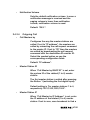
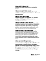
4.3.1
Intercom functionality with ICgraph
In the Full-duplex and in the Half-duplex
configurations everything is the same except
the Intercom functionality.
To use the Intercom functionality the device
must ring before to request the two-way
communication. When ICgraph receives a Ring
request from a device the according point
button will change his color and blink magenta.
At this state select the point and click the
Intercom button to get a two-way
communication.
In the Full-duplex mode / ICgraph configuration
both sites can communicate with each other.
To finish the communication press the “Clear
All” button.
In the Half-duplex mode / ICgraph
configuration the Intercom button will after
activation change to “Intercom Talk” (yellow) in
this mode you can talk to the ringed/selected
device. To listen to the device click on the
“Intercom Talk” button. The button name will
change not to “Intercom Listen” (green).
BARIX AG | 57/91
Illustration 9: ICgraph half-duplex Intercom buttons
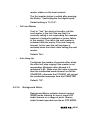
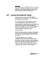
Clicking on the “Intercom Listen” button with
change again to “Intercom Talk button. To
finish the communication press the “Clear All”
button.
Note, for Intercom only one ringing device
should be selected at the same time, no
Groups and not multiple devices! If the device
is not ringing anymore, then the point button
will stay in magenta (none blinking). In this
mode only a one-way communication (to the
device) for max. 10 seconds is possible when
using the Intercom button.
Illustration 10: ICgraph Point button states
BARIX AG | 58/91
5 Implementing example paging
system
5.1
Necessary components
For better understanding the usage of
ICPAGING solution proposed by BARIX we will
try to implement a small paging system,
supporting all the advertised features. For the
system shown below, the following
components are needed:
5.2
•
BARIX Annuncicom 200
•
BARIX Annuncicom 100
•
AIPHONE door panel
•
PS16 Paging station
•
One PS16 48-keys extension (optional)
•
BARIX Exstreamer 100
•
A pair of powered stereo speakers
•
A telephone style door station
•
A PC for streaming music
•
BARIX MP3_RTP_Streamer application
System layout
Let's implement an example system for the
needs of a small shop. The proposed layout is
shown on the figure below:
BARIX AG | 59/91
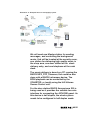
Illustration 11: Example intercom and paging system
We will need one Master station for sending
messages, and controlling the background
music, that will be located at the security room,
one station for delivering high quality music in
the shop area, one door station at the stock
delivery entry, and one telephone at the cash
desk.
The music delivery is done by a PC running the
BARIX MP3_RTP_Streamer, but could be also
done with a BARIX Instreamer device. The
BGM playback can be controlled by the
ICMASTER, or locally using the HAI Volume
Source Control unit.
For the door station BARIX Annuncicom 200 is
being used as it provides the suitable two wire
interface for connecting the AIPHONE panel. As
this device is half duplex, the whole system
needs to be configured in half duplex mode.
BARIX AG | 60/91
5.3
5.3.1
Configuring the master station
Initial setup
Get the latest version of the ICPAGING ABCL
software from BARIX download page. Unzip
the file.
Connect the ICMASTER station to the LAN, and
power it on. Note down the IP address
announced by the Sonic IP, and point the
browser to that address. The application page
of the PS16 will be displayed.
Click on the Update tab of the current installed
firmware, then click on the “Please click here to
start the update” to go to the update page.
You will see the update page. Click on
“Browse”, then navigate to the
update_rescue/compound.bin in the directory
where you have unzipped the
abcl_icpaging_v0xxxxxx.zip file. Select it, then
click on the “Upload” button to continue.
BARIX AG | 61/91
Illustration 12: Device upload web page
Reboot the device when the update is finished,
and open the web UI at the announced IP
address. Once the device reboot click on
DEFAULTS top menu button and apply
defaults. The device will reboot again with
default settings.
Note: default ICPAGING running application is
ICMASTER when “compound.bin” is loaded
and defaults settings are applied. The package
supplied 2 additional binaries,
“update_rescue/compound_master.bin” and
“update_rescue/compound_client.bin”, they
respectively contain ICMASTER or ICCLIENT
as the default running application.
5.3.2
General settings
Now it is time to configure our master station.
Once PS16 is rebooted, open the Settings page
BARIX AG | 62/91
and eventually set up the network settings.
Network setup is not mandatory if a DHCP
server/router exists in the network, anyway, for
example, a fixed IP address instead of default
assigned DHCP address can make the device
access easier in future reconfiguration
operations.
5.3.3
ICMASTER settings
Now it is time to configure the ICMASTER
specific settings. Click on the “Advanced
Settings” tab, and set the following items :
•
Basic Settings or Audio section, Duplex Mode
Choose "Half".
•
Paging section, Group 1 Address Map
Click on the “View/Modify” button to open the
address map configuration dialog, click “Clear
All”, then select id 1 only and click apply. After
device reboot click “Close”.
•
Paging section, Group 2 Address Map
Click on the “View/Modify” button to open the
address map configuration dialog, click “Clear
All”, then select id 2 only and click apply. After
device reboot click “Close”.
•
Paging section, Group 3 Address Map
Click on the “View/Modify” button to open the
address map configuration dialog, click “Clear
All”, then select id 3 only and click apply. After
device reboot click “Close”.
•
Group 4 Address Map
BARIX AG | 63/91
Click on the “View/Modify” button to open the
address map configuration dialog:
We will dedicate this group to select all, then
we need to check clients ID=1, 2 and 3). So
click “Clear All”, select 1, 2, and 3, then click
“Apply” at the bottom of the Group
configuration page. The device will reboot, click
“Close” to exit address map configuration
page.
NB! Do the group key assignment after you
have applied all other ICMASTER settings.
Otherwise the changes will be lost, and only the
group mask will be saved.
After reboot, click CONFIGURATION and
Advanced Settings button, and check if the
number of the selected clients for the groups is
correct. It should look like this:
Illustration 13: Group buttons address bitmap summary
For more detailed explanation on the address
bitmap configuration values see sections
Understanding BARP address bitmaps.
•
Paging section, Audio Multicast Socket
Configure 224.1.2.3, leave the default port as
"12345".
BARIX AG | 64/91
Leave all other settings to their default values,
and click “Apply”. With this the ICMASTER
station configuration is finished.
5.4
5.4.1
Configuring the door station
Initial setup
Do the initial setup as described in the
ICMASTER General settings section. After
uploading the SW, if the default running
application is ICMASTER click REBOOT menu
button and under the “Reboot as” drop down
list select “Intercom Client” and click “Reboot”.
5.4.2
General settings
Now it is time to configure our door station. As
has been done for the master station, once
Annuncicom 200 is rebooted, open
CONFIGURATION and then “Advanced
Settings” page and setup the desired options
int the Network Settings section.
5.4.3
•
Door station settings
BARP Control section, BARP Station ID
Check the client ID to be "1".
BARIX AG | 65/91
•
Audio section, Duplex Mode
Choose "Half".
•
Audio section, Use AI_Phone
Set to "Yes"
•
Background Music section, BGM First Broadcast Port
Playing music on AI_Phone is not possible
because of the two line interface that it is
using, so set it to "0" (no BGM).
Click the “Apply” button to save the settings,
and reboot the device.
5.5
5.5.1
Configuring the cash desk station
Initial setup
Do the initial setup as described in the
ICMASTER General settings section. After
uploading the SW, if the default running
application is ICMASTER click REBOOT menu
button and under the “Reboot as” drop down
list select “Intercom Client” and click “Reboot”.
5.5.2
General settings
Now it is time to configure our door station. As
has been done for the master station, once
Annuncicom 100 is rebooted, open
CONFIGURATION and then “Advanced
BARIX AG | 66/91
Settings” page and setup the desired options
int the Network Settings section.
5.5.3
•
Cash desk settings
BARP Control section, BARP Station ID
Set the client ID "2".
Click the “Apply” button to save the settings,
and reboot the device.
5.6
5.6.1
Configuring the stereo music player
Initial setup
Do the initial setup as described in the
ICMASTER General settings section. After
uploading the SW, if the default running
application is ICMASTER click REBOOT menu
button and under the “Reboot as” drop down
list select “Intercom Client” and click “Reboot”.
5.6.2
General settings
Now it is time to configure our door station. As
has been done for the master station, once
Exstreamer 100 is rebooted, open
CONFIGURATION and then “Advanced
Settings” page and setup the desired options
int the Network Settings section.
In addition, also set the serial port to be used
BARIX AG | 67/91
for the VSC.
•
I/O Control section, Serial Port
Select “VSC Panel.”
5.6.3
•
BGM player settings
BARP Control section, Station ID
Set the client ID "3".
•
Background Music section, BGM Broadcast Address
Set to use multicast address 224.1.2.4.
•
Background Music section, BGM First Broadcast Port
Set to "10501".
•
Background Music section, Available BGM Channels
Set to “3”.
•
Background Music section, BGM Start Channel
Set to “1”.
5.6.4
unit
Connecting the Volume Source Control (VSC)
Unpack the VSC unit from the supplied box.
Turn it upside down. Take a small flat tip
screwdriver and set the arrow of the yellow
switch to point to “1”.
Take a LAN cable with the necessary length,
and plug it in the VSC RJ-45 socket.
BARIX AG | 68/91
Connect the other end of the LAN cable to the
DSUB9-RJ452 adapter. Plug the adapter in the
RS-232 port at the back panel of the
Exstreamer 100 screwing it for more reliable
connection.
Reboot the Exstreamer 100 to recognise the
newly connected VSC unit.
Now the VSC unit should be functional. After
reboot, the default BGM channel should be
displayed (for.ex. “1”). Rotating the knob
left/right decreases/increases the volume.
Pressing the knob switches to “channel” mode,
the rotation changes the channel being played.
If channel “0” is selected, then “Lo” (meaning
local line input channel) is displayed.
5.7
5.7.1
Configuring the PC for BGM distribution
Hardware requirements
For music distribution we need a computer that
can run the BARIX MP3_RTP_Streamer
application which creates several streams from
MP3 library. Any recent Windows/Linux/iMac
computer running Java VM should work.
5.7.2
Configuring the MP3_RTP_Streamer
Download the MP3_RTP_Streamer from the
BARIX web site. Unzip it in a separate
2
This DSUB9-RJ45 adapter is sold separately. Please contact BARIX for more
information.
BARIX AG | 69/91
directory, and run the MP3_RTP_Streamer.jar.
The application window should look like this:
Illustration 14: MP3_RTP_Streamer main window (unconfigured)
We're going to configure it to play the 3 BGM
channels, plus the “local” channel. The three
BGM channels will stream from ports 10501,
10502, 10503, while the local channel expect
audio input from local line in, for devices that
supports the “line” HW input. Double click at
the MP3_RTP streamer window to open the
channel add dialog:
Illustration 15: MP3_RTP_Streamer configuration dialog
Put the channel name first, ex. “Channel 1” for
channel “1”
Set the IP to the multicast group 224.1.2.4, and
the port to 10501
Click “Music lib/dir” and navigate to the
BARIX AG | 70/91
directory where your mp3 files and playlists
reside.
Click “Playlist” and select the playlist for this
channel. The playlists can be created with
iTunes, WinAmp, or any other mp3 capable
player.
Click on “Create” and repeat all these steps to
add channels 2 and 3, using ports 10502
and10503.
Now the MP3_RTP_streamer is configured, and
should be streaming music on address
224.1.2.4 and ports 10501-10503
5.8
Testing the Paging system
5.8.1
Recording a custom message
The ICMASTER allows the user to pre-record
an announcement to be sent when desired to
the selected targets.
Make sure there are no clients selected (by
pressing the “Cancel Sel” key (key 7). Keep
pressed the custom message key (key 6, lcd
display will show a warning "Nothing
Selected"), then press key 5 and release it to
start recording (key 6 can be released from
now). “Recording custom message” will be
displayed on the PS16 LCD. Press again key 5
a second time to stop recording and save the
message to the USB stick.
BARIX AG | 71/91
5.8.2
Rejecting a call
Press the call button on the Door, or cash desk
station. Wait for the ICMASTER to display the
message with the caller ID, and play the ring
tone, then press key 3 to reject the call. The
client should play the busy tone.
5.8.3
Answer a call
Press again the call button on the client. When
the call indication is received on the master,
press key 1, and keep it pressed for a while. As
it is a PTT key, the ICCLIENT is switched to
listen mode when pressed, and to talk mode
when released.
Release the key to listen to the client, and push
it again to talk. Press key 2 to toggle the relay
on the client, or key 3 to hang up the call
5.8.4
Paging
Select the desired clients to be paged by
pressing the corresponding target (group)
buttons, then press and hold the page key (key
2) to send the message. Release it when
finished.
5.8.5
Paging the custom message
With a group selection active, press the custom
message key once. The prerecorded message
will be sent to the selected Ids, and once the
message has been sent the ICMASTER will
BARIX AG | 72/91
return to idle mode. The LED will blink while
sending, and the BGM playback should be
restored after the message is sent.
BARIX AG | 73/91
6
Additional information
6.1 Updating a device using the RS-232
serial port
Sometimes when the device is not accessible
via the LAN, or the image in the flash memory is
corrupted for some reason, then a serial rescue
may be needed to reset the device to the
factory defaults3.
So, here are the steps that need to be executed
to do the serial rescue:
•
Disconnect the device from the power supply
•
Connect the COM port of the device to the COM port of
your computer via a null modem serial cable
•
Open a terminal in the update_rescue directory in your
unzipped copy of the ABCP ICPAGING firmware. If using
Linux or Mac, switch to update_rescue/linux directory
•
Start the rescue process by executing serialX, where X is
the number (1-4) of the serial port on the computer
•
If running on Linux /Mac execute the seriald.sh script,
giving the device name of your COM port as a parameter.
For ex.:
seriald /dev/tty.UC-232AC
•
Power on the device, and wait for the update to finish. The
device will reboot automatically.
NOTE: All other settings except the network
3
Rescuing the PS16 using the serial port is more complex, and requires some
engineering work. Please contact BARIX Support to get more information.
BARIX AG | 74/91
settings will be lost !
6.2
Restoring Factory Defaults of PS16
This new feature has been added as a software
replacement for the missing reset button in
PS16 stations.
In some cases (forgot web UI password,
loading corrupted FW image, etc.) the access
to the web UI of the ICMASTER may be lost. In
such a situation the one of the possible
recovery solutions on the BARIX devices is to
press and hold the reset button while powered
on 4. The device will revert to factory defaults,
and reboot.
However, since PS16 stations do not have HW
reset button, this procedure is not applicable.
In this case follow the procedure below to
revert to factory defaults:
4
•
Press and hold key 1 (lower left) at
startup. A message will appear on
the display asking you to confirm;
•
To confirm press key 16 (upper
right) within 3 seconds, without
releasing key 1, otherwise the unit
will continue booting normally;
•
After confirming and releasing all
keys, the factory defaults are
restored and the unit reboots.
Listen to the SonicIP and note
down the IP address.
Another recovery solution is to do a serial rescue using the serial port (see
section Updating a device using the RS-232 serial port ).
BARIX AG | 75/91
•
Open the web page at the
announced IP address, and change
the application from “ICCLIENT” to
“ICMASTER”. Click “Apply to
reboot.
After reboot, reconfigure the ICMASTER as it
was before.
6.3 Configuring ICPAGING in multimaster
environment
In some cases, multiple masters may be
needed in the paging system. For example, a
door station may need to ring to the reception
at the entrance during normal working hours,
and to the security room at night.
For this purpose, ICPAGING supports several
multimaster scenarios:
6.3.1
Call Failover scenario:
In this case maximum 4 masters can be called
by the client. If one of the first two masters in
the client IP/ID list are called, and it is in "call
reject mode" then the client starts calling the
other three masters in a chain. However, if the
first master does not reply (or any other master
called in the chain) then the client will timeout,
and may not connect to any master. To prevent
this happen, the "Call next Master" on the
client must be enabled.
BARIX AG | 76/91
6.3.2
Call all masters scenario
For that mode the masters must be addressed
by IP. This is done by setting the ICCLIENT
Call Masters by and the ICMASTER Call Master
by configuration options to “IP Address”.
Then it is enough to set one of the first two
master IP addresses in the ICCLIENT list to IP
address 0.0.0.0. In this case, when the call
button associated with that IP address is
pressed, then the call request is broadcasted
to all masters, and one of them may pickup.
The masters track the current state of the
calling client status message, and if it changes
to something other that 3 (connecting) then
they stop ringing. The masters also stop ringing
if more than 5 seconds have elapsed after the
last call request command, sent from the client.
6.3.3
Call all + failover scenario:
Configured as call all masters scenario.
However, if there is one master in a call reject
mode, the client will get the reject and start
calling the other masters in the list by sending
unicast call requests. The masters that got the
broadcasted call request shall stop ringing.
6.4
Understanding BARP address bitmaps
According to BARP protocol, the address
bitmap is 128 bytes, allowing to address client
IDs 1-1024 (starting from "1", client ID=0 is not
valid). In the ICMASTER application, because of
the limited memory space in the EEPROM only
BARIX AG | 77/91
the first 16 bytes can be stored, thus allowing
to group select only the first 128 client IDs.
Each byte addresses 8 clients (for ex. byte 0
addresses clients IDs 1-8, byte 1 addresses
client IDs 9-16, etc.) Setting a bit within a byte
enables the corresponding client, clearing the
bit-disables it.
However, the client IDs within a byte are stored
in reversed order, i.e. the smallest ID is stored
in the MSB, the biggest at the LSB. The
composed address map is then transmitted
with the smallest byte numbers first, as shown
on the picture below:
Byte0
Byte 127
Client Ids 1-8 (bits 7-0)
Client Ids 1017-1024 (bits 7-0)
Bits
6
5
4
3
2
1
0
7 6 5 4 3 2 1 0 ........
7
Client ID
1 2 3 4 5 6 7 8 ........ 1017 1018 1019 1020 1021 1022 1023 1024
Enable/Disable 1 0 1 0 1 0 1 0 ........
0
0
0
0
0
0
0
0
Hex
A
A
0
0
Illustration 16: Address bitmap encoding
To find out in which byte is the client ID we
would like to select, we use the integer division
operation:
IDbyte=Client ID−1/ 8
Let's see what it means in terms of our
example. Let's find in which byte is our client ID
21:
IDbyte=(21-1)/8=2
The result is the biggest number, which
multiplied by 8 does not exceed (ID-1). The
other result from this operation is called
reminder, and is in fact the number that
completes to ID-1:
BARIX AG | 78/91
ID-1 = result*8 + reminder
Now, to find which bit within this byte, we take
the reminder (which for ID-21 is 4) from the
integer division, and subtract it from 7. In other
words:
IDbit =7 – 4 = 3
which means that we have to set bit3 from
byte2:
Byte0
Byte1
Byte2
Client Ids 1-8
Client Ids 9-16
Client Ids 17-24
Bits
7 6 5 4 3 2 1 0 7 6 5 4 3 2 1 0 7 6 5 4 3 2 1 0
Enable/Disable 0 0 0 0 0 0 0 0 0 0 0 0 0 0 0 0 1 0 0 0 1 0 0 0
Hex
0
0
0
0
8
8
Repeating these calculations for client ID=17,
we find that bit7 of byte2 has to be set. Looking
at the BIN / DEC / HEX conversion table, we
see that 1000 is 0x8 in HEX format, which
explains the 0x88 value we see for group 1 in
the Group buttons address bitmap summary.
6.5
BIN / DEC / HEX conversion
Hexadecimal digits have values from 0..15,
represented as 0..9 and as A (for 10) to F (for
15).
The following table can serve as a conversion
chart:
Bin /DEC / Hex Table
Decimal
Binary
Hexadecimal
0
1
0000
0001
0
1
BARIX AG | 79/91
Decimal
Binary
Hexadecimal
2
3
4
5
6
7
8
9
10
11
12
13
14
15
0010
0011
0100
0101
0110
0111
1000
1001
1010
1011
1100
1101
1110
1111
2
3
4
5
6
7
8
9
A
B
C
D
E
F
To convert a binary value in a hexadecimal
representation, the upper and lower four bits
are treated separately, resulting in a two-digit
hexadecimal number.
BARIX AG | 80/91
7
Troubleshooting
Below just a brief table to help solving the main
known issues.
1SSUE Description
Possible cause and remedy action
1
Device boot but web UI home
page frames shows ERROR
400.
ICPAGING has been uploaded over an
existing different ABCL fw based
application.
Click “DEFAULTS” on the top menu and
apply defaults.
2
Device not visible in the LAN
network.
An IP assignment server is missing in the
LAN, or there could be a LAN cable
issue.
Check device LAN cable connections,
eventually set firmware defaults through
keeping pressed the device front panel
reset button for more than 10 seconds,
then listen to SonicIP.
If the above don’t solve the issue try the
serial rescue process (see par. 6.1).
3
Audio is missing.
Volume level is set to 0, mic or speakers
wiring is defective.
Check the volume level, (client Audio
>Default Paging Volume, master Audio >
Default Volume fields), to be greater than
0. Check also mic and speakers to be
well connected to the device.
4
Audio corrupted.
Client device has an audio format set
different from the master.
Check “Audio Format” field, under
CONFIGURATION > Advanced Settings >
Audio section. All devices in the system
MUST have the same audio format set.
5
Annuncicom 100/200 master
device not working.
USB key is not connected to the device.
Insert a USB key.
6
ICCLIENT locked in “PAGING” Master could have been rebooted while
state.
paging.
Once master is up, re-page locked
devices and close the paging session.
BARIX AG | 81/91
7
Device not responding in the
serial update process.
Another PC task can be holding the serial
port.
Check for other PC programs/tasks using
the same serial port and terminate them.
Restart the update procedure.
BARIX AG | 82/91
8
8.1.1
Dictionary
DHCP
Short for Dynamic Host Configuration Protocol,
a protocol used to assign an IP address to a
device connected to a Network.
8.1.2
FDX
Short for Full Duplex. A full-duplex system
allows communication between two parties to
be done in both directions simultaneously. See
this Wikipedia article for more information.
8.1.3
HDX
Short for Half Duplex. In a half-duplex system
simultaneous communication in both directions
is not possible, i.e. if one of the parties is
sending, the other have to wait it to finish
before replying. See this Wikipedia article for
more information.
8.1.4
IP
Short for Internet Protocol, the IP is an address
of a computer or other network device on a
network using IP or TCP/IP. Every device on an
IP-based network requires an IP address to
identify its location or address on the network.
Example: 192.168.2.10
BARIX AG | 83/91
8.1.5
IPzator
Barix IPzator™ technology is designed for the
purpose that the Barix device can create its
own IP address according to the network
structure in case it can’t receive one from your
network. If DHCP, AUTOIP or BOOTP fail,
IPzator will create an IP address within the
subnet and test it (starting with x.x.x.168 and
if occupied incrementing by one). If the address
works and is not being used by another device
on the network, it will give the address to the
Barix device.
8.1.6
MAC address
Abbreviation for Medium Access Control, a
MAC is a unique address number formatted in
hexadecimal format and given to each
computer and/or network device on a
computer network. Because a MAC address is
a unique address a computer network will not
have the same MAC address assigned to more
than one computer or network device.
Example: A1:B2:C3:D4:E5:F6
8.1.7
Netmask
A number used to identify a sub network so
that an IP address can be shared on a LAN
(Local Area Network).
A mask is used to determine what subnet an IP
address belongs to. An IP address has two
components, the network address and the host
address. For example, consider the IP address
150.215.017.009 . Assuming this is part of a
BARIX AG | 84/91
Class B network, the first two numbers (150.2.)
represent the Class B network address, and the
second two numbers (.017.009 ) identify a
particular host on this network.
The Netmask would then be 255.255.0.0 .
8.1.8
Static IP
A Static IP is a fixed IP address that you assign
manually
to a device on the network. It remains valid until
you disable it.
8.1.9
VSC
Volume Source Control unit. This an universal
wall mountable control accessory for the Barix
audio products range. It provides two digit LED
display, control knob, and a IR port.
8.1.10
IP Addressing
An IP address is a 32 bit value, divided into four
octets of eight bits each. The standard
representation is four decimal numbers (in the
range of 0..255), divided by dots.
• Example: 192.2.1.123
This is called decimal-dot notation. The IP
address is divided in two parts: a network and
a host part. To support different needs, five
”network classes” have been defined.
Depending on the network class, the last one,
BARIX AG | 85/91
two or last three bytes define the host, while
the remaining part defines the network. In the
following text, ‘x’ stands for the host part of the
IP address.
8.1.11
Class A network
• IP address 1.x.x.x to 127.x.x.x
Only 127 different networks of this class exist.
These have a very large number of potential
connected devices (up to 16'777'216)
• Example: 10.0.0.1 (network 10, host 0.0.1)
8.1.12
Class B network
• IP address 128.0.x.x to 191.255.x.x
These networks are used for large company
networks. Every network can consist of up to
65534 devices.
• Example: 172.1.3.2 (network 172.1, host
3.2)
8.1.13
Class C network
• IP address 192.0.0.x to 223.255.255.x
Class C networks are most common and for
smaller companies. These networks can
consist of a maximum number of 254hosts.
• Example: 192.7.1.9 (network 192.7.1 , host
9)
BARIX AG | 86/91
8.1.14
Class D network
The remaining addresses 224.x.x.x 239.x.x.x are defined as ”Class D” and are
used as multicast addresses.
8.1.15
Class E network
No addresses are allowed with the four highest
order bits set to “1” (240.x.x.x – 254.x.x.x ).
These addresses, called "class E", are
reserved.
8.1.16
Network Address
The host address with all host bits set to "0" is
used to address the network as a whole (for
example in routing entries).
• Example: 192.168.0.0
Network addresses can not be used as a host
address!
8.1.17
Broadcast Address
The address with the host part bits all set to ”1”
is the broadcast address, meaning ”for every
host”.
• Example: 192.168.0.255
Broadcast addresses can not be used as a
host address!
BARIX AG | 87/91
8.1.18
IP Netmask
The Netmask is used to divide the IP address
differently from the standard defined by the
classes A,B and C.
Entering a Netmask, it is possible to define how
many bits from the IP address are to be taken
as the network part and how many bits are to
be taken as the host part.
Standard IP network Netmask:
Class
Network bits
A
B
C
8
16
24
Host
bits
24
16
8
Netmask
255.0.0.0
255.255.0.0
255.255.255.0
Netmask examples:
Netmask
255.255.255.252
255.255.255.248
255.255.255.240
255.255.255.224
255.255.255.192
255.255.255.128
255.255.255.0
255.255.254.0
255.255.252.0
255.255.248.0
.
.
255.128.0.0
255.0.0.0
2
3
4
5
6
7
8
9
10
11
.
.
23
24
Host bits
BARIX AG | 88/91
8.1.19
Private IP Networks and the Internet
If your network is not connected to the Internet
and there are no plans to make such a
connection you may use any IP address you
wish.
However if you are not connected to the
Internet and have plans to connect to the
Internet or you are connected to the Internet
and want to operate your Barix Barionet on an
intranet you should use one of the subnetworks below for your network. These
network numbers have been reserved for such
networks. If you have any questions about IP
assignment ask your Network Administrator.
Private IP networks by class:
Class
A
B
C
8.1.20
Network
10.x.x.x
172.16.x.x
192.168.0.x
Network RFC’s
For more information regarding IP addressing
see the following documents. They can be
found on the Internet:
RFC
950
1700
1117
1597
Description
Internet Standard Subnetting Procedure
Assigned Numbers
Internet Numbers
Address Allocation for Private Internets
BARIX AG | 89/91
9
Legal Information
© 2013 Barix AG, Zurich, Switzerland.
All rights reserved.
All information is subject to change without
notice.
All mentioned trademarks belong to their
respective owners and are used for reference
only.
Barix and ICPAGING are trademarks of Barix
AG, Switzerland and are registered in certain
countries.
For information about our devices and the
latest version of this manual please visit
www.barix.com.
BARIX AG | 90/91
Illustration Index
Illustration 1: ICMASTER keyboard layout.................................................17
Illustration 2: ICMASTER home page.........................................................22
Illustration 3: ICMASTER basic settings page............................................23
Illustration 4: ICMASTER advanced settings page....................................26
Illustration 5: ICCLIENT home page............................................................39
Illustration 6: ICCLIENT Application “basic settings” Web Page..............41
Illustration 7: ICCLIENT Application “advanced settings” Web Page.......42
Illustration 8: ICgraph application (Full-duplex).........................................54
Illustration 9: ICgraph half-duplex Intercom buttons.................................58
Illustration 10: ICgraph Point button states................................................58
Illustration 11: Example intercom and paging system...............................60
Illustration 12: Device upload web page....................................................62
Illustration 13: Group buttons address bitmap summary..........................64
Illustration 14: MP3_RTP_Streamer main window (unconfigured)............70
Illustration 15: MP3_RTP_Streamer configuration dialog..........................70
Illustration 16: Address bitmap encoding...................................................78
Barix AG
Seefeldstrasse 303
8008 Zürich
SWITZERLAND
T
+41 43 433 22 11
F
+41 44 274 28 49
www.barix.com
[email protected]
[email protected]
BARIX AG | 91/91