1
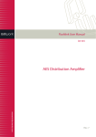
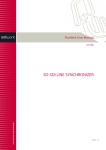
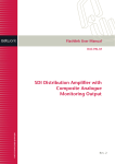
Flashlink User Manual
ADC-SDI-CC
Multi standard NTSC, PAL, YPbPr,
RGB-Decoder/Converter
Component and Composite
Analogue Video Converter
network-electronics.com
Rev. 3
ADC-SDI-CC
Rev. 3
DATE: 23 July 2008
Revision history
The latest version is always available in pdf-format on our web-site:
http://www.network-electronics.com/
Current revision of this document is the uppermost in the table below.
Revision Replaces Date
Change Description
3
2
2008-07-14
Added Declaration of Conformity.
2
1
2007-10-23
New front page and removed old logo.
1
0
2007-10-09
Added Materials Declaration and EFUP
0
B
03.03.05
Specification update and changed ConQuer to
flashlink®.
B
A
02.09.04
First preliminary release
A
12.08.04
Network Electronics AS, P.O.Box 1020, N-3204 Sandefjord, Norway. Tel.: +47 33 48 99 99 – Fax: +47 33 48 99 98
E-mail: [email protected] – Web: http://www.network-electronics.com/
Technical specifications are subject to be changed without notice.
2
ADC-SDI-CC
Rev. 3
DATE: 23 July 2008
Index
Quick Start Guide for ADC-SDI-CC.........................................................................................................4
1. General......................................................................................................................................................5
2. Specifications............................................................................................................................................6
3. Connector module....................................................................................................................................7
3.1 Correspondence of connectors and signals.........................................................................................7
3.2 Mounting the connector module ..........................................................................................................7
4. Configuration and Setup.........................................................................................................................8
4.1 Setting the DIP switches ......................................................................................................................8
4.2 Reset...................................................................................................................................................10
5. Module status .........................................................................................................................................11
5.1 GPI ALARM – Module Status Outputs ..............................................................................................11
5.2 Front Panel - Status Monitoring .......................................................................................................12
6. Interface with GYDA and RS-422 command set ................................................................................13
6.1 ADC-SDI-CC Command table...........................................................................................................13
6.2 The “?” command .............................................................................................................................13
6.3 The “info” command .........................................................................................................................14
6.4 Video modes commands.....................................................................................................................14
6.5 Mark Field 1, Pedestal and Comb - commands. ...............................................................................15
6.6 get, set, eget and eset. ........................................................................................................................15
General environmental requirements for Network flashlink® equipment...........................................16
Product Warranty .....................................................................................................................................17
Materials declaration and recycling information ...................................................................................18
Materials declaration ................................................................................................................................18
Environmentally-friendly use period.......................................................................................................18
Recycling information ...............................................................................................................................19
EC Declaration of Conformity .................................................................................................................20
Network Electronics AS, P.O.Box 1020, N-3204 Sandefjord, Norway. Tel.: +47 33 48 99 99 – Fax: +47 33 48 99 98
E-mail: [email protected] – Web: http://www.network-electronics.com/
Technical specifications are subject to be changed without notice.
3
ADC-SDI-CC
Rev. 3
DATE: 23 July 2008
Quick Start Guide for ADC-SDI-CC
Without GYDA controller (This is the default setting upon shipping)
1. Set DIP-switch 1 on (towards backplane), switches 2 and 3 according to the input mode you want (see
Table 2 on page 9).
2. Insert ADC-SDI-CC into a slot in the sub-rack.
3. Attach Analogue input (CVBS, S-Video, RGB+sync or YPbPr) and SDI-output to the backplane
module (see Figure 2 on page 7).
4. Power on. After some seconds the ADC-SDI-CC will be running, and the input detected. All LED’s
will be green and the SDI output active. If this is not the case, please see section 5.2 Front Panel Status Monitoring on page 12.
With GYDA controller (firmware> 1.1)
Insert ADC-SDI-CC into a slot in the sub-rack.
Attach Analogue input (CVBS, S-Video, RGB+sync or YPbPr) and SDI-output to the backplane module
(see Figure 2 on page 7).
Power on. After a few seconds the ADC-SDI-CC will be running, and the card detected by GYDA. Use
GYDA to set up which analogue video format to use, CVBS, S-Video, RGB+sync or YPbPr. All
LED’s will now be green and the SDI output active. The card settings are stored on the card which
means that the card will remember its configuration despite any eventual power loss.
Network Electronics AS, P.O.Box 1020, N-3204 Sandefjord, Norway. Tel.: +47 33 48 99 99 – Fax: +47 33 48 99 98
E-mail: [email protected] – Web: http://www.network-electronics.com/
Technical specifications are subject to be changed without notice.
4
ADC-SDI-CC
Rev. 3
DATE: 23 July 2008
1. General
The flashlink ® ADC-SDI-CC is a high quality digital video decoder that digitises and decodes all
popular baseband video formats into SDI 4:2:2 digital component video. The ADC-SDI-CC supports the
analogue-to-digital conversion of component RGB and YPbPr signals, as well as the decoding of NTSC
and PAL composite and S-video into component digital video. This decoder features four 10-bit A/D
converters running with 2 x oversampling (27MHz), which are then digitally filtered and decimated to the
1 x pixel rate giving a higher signal-to-noise ratio for each input channel.
When used with the GYDA control system, gain adjustments may be made to each analogue input.
Composite video decoding utilises a 5-line adaptive comb filter for both the luma and chroma signal
paths to reduce cross-luma and cross-chroma artefacts. A alternative chroma trap filter is also available.
On composite and S-video inputs, the user can control video characteristics such as contrast, brightness,
saturation and hue via the GYDA control interface. The GYDA system controller is used with all
flashlink and flashlink modules providing a common control and monitoring platform.
ADC-SDI-CC features:
•
•
•
•
•
•
•
•
Multi-standard NTSC, PAL, YPbPr, RGB Decoder/Converter
10 bit 4:2:2 SDI video quality
5 line adaptive comb filter for NTSC/PAL decoding
EDH generation and insertion
2 x oversampling of both composite and component video
10 bit component 8:8:8 oversampling with digital 4:2:2 decimation and down-conversion
VBI data transparent
3 SDI outputs
Figure 1 – Simplified block diagram of the ADC-SDI-CC card
Network Electronics AS, P.O.Box 1020, N-3204 Sandefjord, Norway. Tel.: +47 33 48 99 99 – Fax: +47 33 48 99 98
E-mail: [email protected] – Web: http://www.network-electronics.com/
Technical specifications are subject to be changed without notice.
5
ADC-SDI-CC
Rev. 3
DATE: 23 July 2008
2. Specifications
Digital Serial Output
Signal type:
Connector:
Impedance:
Return loss:
Jitter:
Peak to peak signal level:
Composite and Y/C Input:
Signal type:
Connector:
Impedance:
Signal level:
Return loss:
Component and RGB Input:
Signal rate:
Signal type:
SMPTE 259M / ITU-R BT.601
BNC
75 ohm
>15dB @ 270MHz
< 0.2UI
800mV ± 80mV
Composite video, PAL 625/50Hz or NTSC 525/60Hz
Y / C (S-video)
BNC
75 ohm
1Vp-p
>40dB
Connector:
Impedance:
Signal level:
Return loss:
625/50Hz or 525/60Hz
RGB without setup, with separate sync.
SMPTE / EBU Y, Cr, Cb
BNC
75 ohm
Y = 1Vp-p. Cb, Cr, R, G, B = 0.7Vp-p
>40dB
Processing Performance:
Signal path:
Sampling:
Luma/Chrome separation:
Video bandwidth:
Hue Accuracy
Colour Saturation Accuracy
Luminance Nonlinearity
SNR (unified weighted):
Diff. gain:
Diff. phase:
Video processing delay
10 bits
27MHz, 2 x oversampling
selectable 5 line adaptive comb filter or chroma trap filter
6MHz
0.5° typical
0.8% typical
0.6% typical
66dB typical
<1.0%
<1.0°
3 video lines
Power:
+5V DC / 2.75W
-15V DC / 0.5W
Network Electronics AS, P.O.Box 1020, N-3204 Sandefjord, Norway. Tel.: +47 33 48 99 99 – Fax: +47 33 48 99 98
E-mail: [email protected] – Web: http://www.network-electronics.com/
Technical specifications are subject to be changed without notice.
6
ADC-SDI-CC
Rev. 3
DATE: 23 July 2008
3. Connector module
The ADC-SDI-CC has a dedicated connector module: ADC-SDI-CC-C1. This module is mounted at the
rear of the sub-rack. The module is shown in Figure 2 .
Figure 2 - ADC-SDI-CC-C1 connector module.
3.1 Correspondence of connectors and signals
The ADC-SDI-CC-C1 connector module has 7 BNC's:
CVBS/Y
Analogue input: CVBS, SYNC for RGB or S-Video Luma.
R/Pr
Analogue input: Red or component Pr.
G/Y
Analogue input: Green or component Y.
B/Pb/C
Analogue input: Blue, component Pb or S-Video Chroma.
SDI-OUT
Digital SDI output
SDI-OUT
Digital SDI output
SDI-OUT
Digital SDI output
SDI1, SDI2 and SDI3 are equivalent SDI outputs.
Note: The analogue inputs are internally terminated with 75Ω on the ADC-SDI-CC card.
3.2 Mounting the connector module
The details of how the connector module is mounted, is found in the user manual for the sub-rack frame
FR-2RU-10-2.
This manual is also available from our web site: http://www.network-electronics.com/
Network Electronics AS, P.O.Box 1020, N-3204 Sandefjord, Norway. Tel.: +47 33 48 99 99 – Fax: +47 33 48 99 98
E-mail: [email protected] – Web: http://www.network-electronics.com/
Technical specifications are subject to be changed without notice.
7
ADC-SDI-CC
Rev. 3
DATE: 23 July 2008
4. Configuration and Setup
Figure 3 - ADC-SDI-CC simplified silkscreen.
4.1 Setting the DIP switches
The ADC-SDI-CC card has a Dual-Inline switch (DIP-switch) that has 10 individual On/Off switches.
The purpose of these switches is to provide an easy interface to some of the most used features of the
ADC-SDI-CC card, without the need of a GYDA controller. The switches are numbered from '1' towards
the top of the card, see Figure 3 . A switch is off when the tap is placed in direction of the front handle.
Switch #
1
2
3
4
5
Function
Manual mode on/off
Input Channel select
Input Channel select
Mark Field 1 enable on/off
Comb filter/Trap filter
6
Pedestal on/off
7
8
9
10
Reserved
Factory Reset on/off
Reserved
Run mode on/off
Comment
When on, enables switches 2, 3, 4, 5, 6 and 8.
According to Table 3.
When on, the Mark Field 1-feature enabled.
When on, the comb filter is selected. When off, the trap filter
is selected.
If a setup level of 7,5 IRE is present on your analogue video,
set to on. When black level is 0 IRE, set to off. This setting
only applies to 525 lines video standard.
To reset the internal EEPROM.
For factory use only
Table 1: Summary of the DIP switches. Switch 7, 9 and 10 are mainly for factory use, while switches 1, 2,
3, 4, 5 and 6 will be used when no GYDA controller is available.
Switch 1 - Manual mode
Network Electronics AS, P.O.Box 1020, N-3204 Sandefjord, Norway. Tel.: +47 33 48 99 99 – Fax: +47 33 48 99 98
E-mail: [email protected] – Web: http://www.network-electronics.com/
Technical specifications are subject to be changed without notice.
8
ADC-SDI-CC
Rev. 3
DATE: 23 July 2008
Switch 1 is the manual mode switch. If on, the ADC-SDI-CC may be operated with the switches. If off,
the ADC-SDI-CC is to be used with a GYDA controller.
Factory setting is switch 1 in on position
With switch 1 off:
While in automatic mode, switches 2, 3, 4, 5, 6 and 8 do not have any effect.
With switch 1 on:
In manual mode, the functionality of switches 2, 3, 4, 5 , 6 and 8 is as follows:
Switches 2 and 3
These two switches determine the input selection. See Table 2.
Factory setting is switch 2 and switch 3 off.
Sw #3
0
0
1
1
Sw #2
0
1
0
1
Input Channel Select
CVBS
S-Video
YPbPr
RGBS
Table 2: Manual selection of video mode
Switch 4
Switch 4 turns on/off the Mark Field 1-feature. With switch 4 off the Mark Field 1-feature is disabled,
with switch 4 on the Mark Field 1-feature is enabled and the card inserts a marker on line x of each field
1. This features gives improved encoding quality when used with an encoder like the DAC-SDI which
can use this feature.
Factory setting is switch 4 in on position.
Switch 5
Switch 5 selects which filter to use when separating Luma from Chroma in CVBS. With switch 5 on, the
5-line comb filter is selected, with switch 5 off, the chroma trap filter is selected.
Factory setting is switch 5 in on position.
Switch 6
Switch 6 selects whether pedestal is present on the analogue video. With switch 6 on, the black level will
be set to 7,5 IRE. With switch 6 off, the black level will be 0 IRE. This switch only affects 525 lines
video. Typically a black level of 7,5 IRE is used in the USA and 0 IRE in Japan.
Factory setting is switch 6 in on position.
Network Electronics AS, P.O.Box 1020, N-3204 Sandefjord, Norway. Tel.: +47 33 48 99 99 – Fax: +47 33 48 99 98
E-mail: [email protected] – Web: http://www.network-electronics.com/
Technical specifications are subject to be changed without notice.
9
ADC-SDI-CC
Rev. 3
DATE: 23 July 2008
Switches 7 and 9 - Reserved
These switches are reserved and should always be in the off position.
Factory setting are switch 7 and 9 in off position.
Switch 8 - Reset to factory default
ADC-SDI-CC contains an EEPROM which stores the configuration of the card. Switch 8 can be used to
reset the EEPROM to the factory default. Follow the procedure described below.
1
2
3
Action
Power down.
Turn switch 8 on.
Power up.
4
5
Power down.
Turn switch 8 off.
6
Power up.
Comment
Switch 1 must also be turned on for this to have effect.
ADC-SDI-CC enters a special state where the EEPROM is restored to
factory default values. This is flagged by the Card State LED, which starts
to blink yellow.
If you want the DIP switches to be placed in the factory default position,
this is the time to do so: Switch 10 should, as always, be turned to the on
position. Switch 1 may be turned on or off.
The card EEPROM is now reset to factory settings.
Table 3: Method to restore the ADC-SDI-CC card to factory settings. Remember to let some seconds pass
by each time you power down, to allow capacitors to be fully discharged.
Switch 10 - Run mode
Switch 10 is purely used for service upgrade of the ADC-SDI-CC card. It should always be in the on
position. If switch 10 is in the off position, the Card State LED will light up red, and the ADC-SDI-CC
card will enter programming mode. This causes no harm, but the card will not work in this mode.
Factory setting is switch 10 in on position.
4.2 Reset
The push-button just behind the front LEDs is a reset switch, see Figure 3 . It has the same effect as a
power off – power on cycle.
Network Electronics AS, P.O.Box 1020, N-3204 Sandefjord, Norway. Tel.: +47 33 48 99 99 – Fax: +47 33 48 99 98
E-mail: [email protected] – Web: http://www.network-electronics.com/
Technical specifications are subject to be changed without notice.
10
ADC-SDI-CC
Rev. 3
DATE: 23 July 2008
5. Module status
The status of the module can be monitored in two ways.
1. GYDA System Controller (optional).
2. LED’s at the front of the sub-rack.
The LED’s are mounted on the module itself, whereas the GYDA System Controller is a separate module
which gives detailed information on the card status. The functions of the LED’s are described on the next
page. The GYDA controller is described in a separate user manual. This manual is available on our web
site: http://www.network-electronics.com/
5.1 GPI ALARM – Module Status Outputs
These outputs can be used for wiring up alarms for third party control systems. The GPI outputs are open
collector outputs, sinking to ground when an alarm is triggered. The GPI connector is shown in Figure 4 .
Electrical Maximums for GPI outputs
Max current: 100mA
Max voltage: 30V
ADC-SDI-CC module GPI pinning:
Signal
Name
Status
General error status for the module.
Input
No video input detected
VCXO
Module not gen-locked to video input
SDI Output No SDI output present
Ground
0 volt pin
Pin #
Pin 1
Pin 2
Pin 3
Pin 4
Pin 8
Mode
Open Collector
Open Collector
Open Collector
Open Collector
0V.
Figure 4 - GPI Outlet
Network Electronics AS, P.O.Box 1020, N-3204 Sandefjord, Norway. Tel.: +47 33 48 99 99 – Fax: +47 33 48 99 98
E-mail: [email protected] – Web: http://www.network-electronics.com/
Technical specifications are subject to be changed without notice.
11
ADC-SDI-CC
Rev. 3
DATE: 23 July 2008
5.2 Front Panel - Status Monitoring
The status of the module can be easily monitored visually by the LED’s at the front of the module. The
LED’s are visible through the front panel as shown in Figure 5 below.
(Text not printed on the front panel).
Figure 5 - Front panel indicator for ADC-SDI-CC
The ADC-SDI-CC has 4 LED’s each showing status information. The position of the different LED’s is
shown in Figure 5 .
Diode \ state
Card State
Red LED
Module is faulty
Input
No video input
Video input detected
detected
No input detected Input signal is detected.
Input signal is detected,
Video not yet locked or input and properly locked
comes from a VCR
No SDI output
Correct SDI output
VCXO
SDI Output
Yellow LED
Green LED
Start-up-sequence is running Module is OK
Module power is OK
No light
Module has no
power or
memory fault
Table 4 - Front panel LED indicator overview
Network Electronics AS, P.O.Box 1020, N-3204 Sandefjord, Norway. Tel.: +47 33 48 99 99 – Fax: +47 33 48 99 98
E-mail: [email protected] – Web: http://www.network-electronics.com/
Technical specifications are subject to be changed without notice.
12
ADC-SDI-CC
Rev. 3
DATE: 23 July 2008
6. Interface with GYDA and RS-422 command set
All commands follow the flashlink® protocol and can be used for direct control access to the module.
The control system can either be a GYDA or a third-party control system with integrated flashlink®
protocol. The module can also be manually controlled with a VT100 compatible terminal program.
The protocol can be found on our web page; http://www.network-electronics.com
6.1 ADC-SDI-CC Command table
Command
?
info
CVBS
Svideo
RGB
YPbPR
MarkF1 on
MarkF1 off
Comb on
Comb off
Pedestal on
Pedestal off
Calibrate
Response
Yes
Yes
“OK”
“OK”
“OK”
“OK”
“OK”
“OK”
“OK”
“OK”
“OK”
“OK”
“OK”
eget [0xHH]
eset [0xHH] [0xHH]
get [0xHH]
set [0xHH] [0xHH]
Yes
“OK”
Yes
“OK”
Comment
The “Hello” command.
Gives back the card state.
Set video format to CVBS.
Set video format to S-Video.
Set video format to component RGB + sync.
Set video format to component YPbPr.
Turn on the Mark Field 1-feature.
Turn off the Mark Field 1-feature.
Set chroma luma separation filter to 5-line comb filter.
Set chroma luma separation filter to chroma trap filter.
Pedestal is present.
Pedestal is not present.
Calibrates RGB gain. Must be in RGB and input must be 75%
colour bar.
Get a value from a numbered eeprom register.
Set a value to a numbered eeprom register.
Get a value from a numbered register.
Set a value to a numbered register.
Table 5 - All commands available to the user
6.2 The “?” command
According to the flashlink®, no card can use the RS422-bus before it has been activated with the “?”
(hello) command. The response from ADC-SDI-CC will be:
xxxxADC-SDI-CC\
PIC sw rev X.X.X\
FPGA sw rev X\
Protocol ver X.X
Network Electronics AS, P.O.Box 1020, N-3204 Sandefjord, Norway. Tel.: +47 33 48 99 99 – Fax: +47 33 48 99 98
E-mail: [email protected] – Web: http://www.network-electronics.com/
Technical specifications are subject to be changed without notice.
13
ADC-SDI-CC
Rev. 3
DATE: 23 July 2008
Here xxxx denotes the source and destination rack and slot coordinates, while X represents a version
number. As of primo July 2004, these revisions would be:
xxxxADC-SDI-CC\
PIC sw rev 1.0.2\
FPGA sw rev 6\
Protocol ver 1.0
6.3 The “info” command
This command report the entire state of the card. An example:
xxxxCVBS\
Locked 50Hz\
Field 1 mark on\
Comb on\
Pedestal on
Status of
Input Select
Status string
CVBS
Svideo
YpbPr
RGB
Analogue input. Locked 50Hz
Locked 60Hz
Not locked 50Hz
Not locked 60Hz
Field 1 marking Field 1 marking on
Field 1 marking off
Chroma filter
Comb on
Comb off
Pedestal
Pedestal on
Pedestal off
Comment
CVBS is selected
Svideo is selected
YPbPr is selected
RGB is selected
Locked to 625 lines 50 Hz.
Locked to 525 lines 60 Hz.
Not locked, previously locked to 50Hz.
Not locked, previously locked to 60Hz.
The Mark Field 1-feature is turned on.
The Mark Field 1-feature is turned off.
Comb filter selected.
Chroma trap filter is selected.
Pedestal present is selected.
Pedestal not present is selected.
Table 6: The info command broken up in components.
The “info” command is composed by many minor lines, fully specified in table 6. In general, when a
condition is normal, it is not reported. For instance, pedestal is reported when locked to 50Hz, even tough
the setting has no effect on the video.
6.4 Video modes commands.
The CVBS, RGB, Svideo and YPbPr commands sets the video input mode. Remember that RGB -mode
needs separate sync on the CVBS/Luma channel. This sync may be a synchronous CVBS-signal.
Network Electronics AS, P.O.Box 1020, N-3204 Sandefjord, Norway. Tel.: +47 33 48 99 99 – Fax: +47 33 48 99 98
E-mail: [email protected] – Web: http://www.network-electronics.com/
Technical specifications are subject to be changed without notice.
14
ADC-SDI-CC
Rev. 3
DATE: 23 July 2008
6.5 Mark Field 1, Pedestal and Comb - commands.
Commands to turn on/off the Mark Field 1-feature, Pedestal and the Comb filter commands are
straightforward text, see Table 5 .
6.6 get, set, eget and eset.
These commands are for internal factory use. The end-user should avoid these commands.
Network Electronics AS, P.O.Box 1020, N-3204 Sandefjord, Norway. Tel.: +47 33 48 99 99 – Fax: +47 33 48 99 98
E-mail: [email protected] – Web: http://www.network-electronics.com/
Technical specifications are subject to be changed without notice.
15
ADC-SDI-CC
Rev. 3
DATE: 23 July 2008
General environmental requirements for Network flashlink® equipment
1. The equipment will meet the guaranteed performance specification under the following environmental
conditions:
•
•
Operating room temperature range
Operating relative humidity range
0°C to 40°C
up to 90% (non-condensing)
2. The equipment will operate without damage under the following environmental conditions:
•
•
Temperature range
Relative humidity range
-10°C to 50°C
up to 95% (non-condensing)
Network Electronics AS, P.O.Box 1020, N-3204 Sandefjord, Norway. Tel.: +47 33 48 99 99 – Fax: +47 33 48 99 98
E-mail: [email protected] – Web: http://www.network-electronics.com/
Technical specifications are subject to be changed without notice.
16
ADC-SDI-CC
Rev. 3
DATE: 23 July 2008
Product Warranty
The warranty terms and conditions for the product(s) covered by this manual follow the General Sales
Conditions by Network Electronics AS. These conditions are available on the company web site of
Network Electronics AS:
www.network-electronics.com
Network Electronics AS, P.O.Box 1020, N-3204 Sandefjord, Norway. Tel.: +47 33 48 99 99 – Fax: +47 33 48 99 98
E-mail: [email protected] – Web: http://www.network-electronics.com/
Technical specifications are subject to be changed without notice.
17
ADC-SDI-CC
Rev. 3
DATE: 23 July 2008
Materials declaration and recycling information
Materials declaration
For product sold into China after 1st March 2007, we comply with the “Administrative Measure on the
Control of Pollution by Electronic Information Products”. In the first stage of this legislation, content of
six hazardous materials has to be declared. The table below shows the required information.
Toxic or hazardous substances and elements
組成名稱
Part Name
ADC-SDI-CC
鉛
汞
镉
六价铬
多溴联苯
多溴二苯醚
Lead Mercury Cadmium Hexavalent Polybrominated Polybrominated
(Pb)
(Hg)
(Cd)
Chromium
biphenyls
diphenyl ethers
(Cr(VI))
(PBB)
(PBDE)
X
O
O
O
O
O
O: Indicates that this toxic or hazardous substance contained in all of the homogeneous materials for
this part is below the limit requirement in SJ/T11363-2006.
X: Indicates that this toxic or hazardous substance contained in at least one of the homogeneous
materials used for this part is above the limit requirement in SJ/T11363-2006.
Environmentally-friendly use period
The manual must include a statement of the “environmentally friendly use period”. This is defined as the
period of normal use before any hazardous material is released to the environment. The guidance on how
the EFUP is to be calculated is not finalised at the time of writing. See
http://www.aeanet.org/GovernmentAffairs/qfLeOpAaZXaMxqGjSFbEidSdPNtpT.pdf for an unofficial
translation of the draft guidance. For our own products, Network Electronics has chosen to use the 50
year figure recommended in this draft regulation.
Network Electronics suggests the following statement on An “Environmentally Friendly Use Period”
(EFUP) setting out normal use:
EFUP is the time the product can be used in normal service life without leaking the hazardous materials. We expect the normal
use environment to be in an equipment room at controlled temperature range (0ºC - 40ºC) with moderate humidity (< 90%, noncondensing) and clean air, not subject to vibration or shock.
Further, a statement on any hazardous material content, for instance, for a product that uses some tin/lead
solders:
Where a product contains potentially hazardous materials, this is indicated on the product by the appropriate symbol containing
the EFUP. The hazardous material content is limited to lead (Pb) in some solders. This is extremely stable in normal use and the
EFUP is taken as 50 years, by comparison with the EFUP given for Digital Exchange/Switching Platform in equipment in
Appendix A of “General Rule of Environment-Friendly Use Period of Electronic Information Products”. This is indicated by the
product marking:
Network Electronics AS, P.O.Box 1020, N-3204 Sandefjord, Norway. Tel.: +47 33 48 99 99 – Fax: +47 33 48 99 98
E-mail: [email protected] – Web: http://www.network-electronics.com/
Technical specifications are subject to be changed without notice.
18
ADC-SDI-CC
Rev. 3
DATE: 23 July 2008
50
It is assumed that while the product is in normal use, any batteries associated with real-time clocks or battery-backed RAM will
be replaced at the regular intervals.
The EFUP relates only to the environmental impact of the product in normal use, it does not imply that the product will
continue to be supported for 50 years.
Recycling information
Network Electronics provides assistance to customers and recyclers through our web site
http://www.network-electronics.com. Please contact Network Electronics’ Customer Support for
assistance with recycling if this site does not show the information you require.
Where it is not possible to return the product to Network Electronics or its agents for recycling, the
following general information may be of assistance:
Before attempting disassembly, ensure the product is completely disconnected from power and signal
connections.
All major parts are marked or labelled to show their material content.
Depending on the date of manufacture, this product may contain lead in solder.
Some circuit boards may contain battery-backed memory devices.
Network Electronics AS, P.O.Box 1020, N-3204 Sandefjord, Norway. Tel.: +47 33 48 99 99 – Fax: +47 33 48 99 98
E-mail: [email protected] – Web: http://www.network-electronics.com/
Technical specifications are subject to be changed without notice.
19
ADC-SDI-CC
Rev. 3
DATE: 23 July 2008
EC Declaration of Conformity
Network Electronics AS
P.B. 1020, N-3204 SANDEFJORD, Norway
MANUFACTURER
AUTHORISED REPRESENTATIVE
(Established within the EEA)
Not applicable
MODEL NUMBER(S)
ADC-SDI-CC
DESCRIPTION
Component and Composite Analogue Video Converter
DIRECTIVES this equipment complies with
LVD 73/23/EEC
EMC 2004/108/EEC
HARMONISED STANDARDS applied in order to
verify compliance with Directive(s)
EN 55103-1:1996
EN 55103-2:1996
TEST REPORTS ISSUED BY
Notified/Competent Body
Report no:
Nemko
E07379.00
TECHNICAL CONSTRUCTION FILE NO
Not applicable
YEAR WHICH THE CE-MARK WAS AFFIXED
2008
TEST AUTHORIZED SIGNATORY
MANUFACTURER
AUTHORISED REPRESENTATIVE
(Established within EEA)
Date of Issue
2008-07-14
Place of Issue
Not applicable
Name
Thomas Øhrbom
Position
Quality Manager
(authorised signature)
Sandefjord, Norway
Network Electronics AS, P.O.Box 1020, N-3204 Sandefjord, Norway. Tel.: +47 33 48 99 99 – Fax: +47 33 48 99 98
E-mail: [email protected] – Web: http://www.network-electronics.com/
Technical specifications are subject to be changed without notice.
20