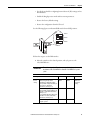
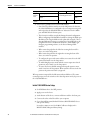
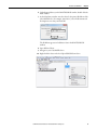
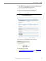
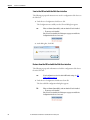
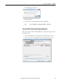
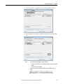
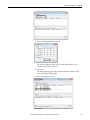
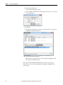
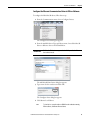
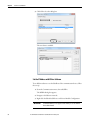
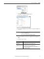
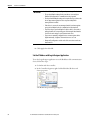
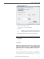
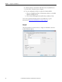
1
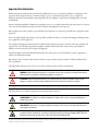
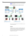
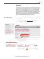
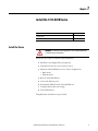
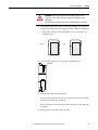
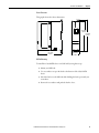
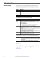
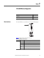
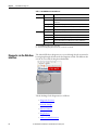
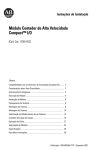
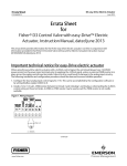
User Manual
Configurable NAT Router
Catalog Number 1783-NATR
Important User Information
Read this document and the documents listed in the additional resources section about installation, configuration, and
operation of this equipment before you install, configure, operate, or maintain this product. Users are required to
familiarize themselves with installation and wiring instructions in addition to requirements of all applicable codes, laws,
and standards.
Activities including installation, adjustments, putting into service, use, assembly, disassembly, and maintenance are required
to be carried out by suitably trained personnel in accordance with applicable code of practice.
If this equipment is used in a manner not specified by the manufacturer, the protection provided by the equipment may be
impaired.
In no event will Rockwell Automation, Inc. be responsible or liable for indirect or consequential damages resulting from the
use or application of this equipment.
The examples and diagrams in this manual are included solely for illustrative purposes. Because of the many variables and
requirements associated with any particular installation, Rockwell Automation, Inc. cannot assume responsibility or
liability for actual use based on the examples and diagrams.
No patent liability is assumed by Rockwell Automation, Inc. with respect to use of information, circuits, equipment, or
software described in this manual.
Reproduction of the contents of this manual, in whole or in part, without written permission of Rockwell Automation,
Inc., is prohibited.
Throughout this manual, when necessary, we use notes to make you aware of safety considerations.
WARNING: Identifies information about practices or circumstances that can cause an explosion in a hazardous environment,
which may lead to personal injury or death, property damage, or economic loss.
ATTENTION: Identifies information about practices or circumstances that can lead to personal injury or death, property
damage, or economic loss. Attentions help you identify a hazard, avoid a hazard, and recognize the consequence.
IMPORTANT
Identifies information that is critical for successful application and understanding of the product.
Labels may also be on or inside the equipment to provide specific precautions.
SHOCK HAZARD: Labels may be on or inside the equipment, for example, a drive or motor, to alert people that dangerous
voltage may be present.
BURN HAZARD: Labels may be on or inside the equipment, for example, a drive or motor, to alert people that surfaces may
reach dangerous temperatures.
ARC FLASH HAZARD: Labels may be on or inside the equipment, for example, a motor control center, to alert people to
potential Arc Flash. Arc Flash will cause severe injury or death. Wear proper Personal Protective Equipment (PPE). Follow ALL
Regulatory requirements for safe work practices and for Personal Protective Equipment (PPE).
Allen-Bradley, Rockwell Software, Rockwell Automation, RSLinx Classic, Stratix 5700, Stratix 5900, Studio 5000, and Studio 5000 Logix Designer are trademarks of Rockwell Automation, Inc.
Trademarks not belonging to Rockwell Automation are property of their respective companies.
Preface
The 1783-NATR is a network device with Embedded Switch Technology
capable of doing Network Address Translation (NAT) for applications using
Device Level Ring (DLR) or linear topologies. The 1783-NATR device can be
used to connect a small private network (for example, a machine network) to a
larger plant-wide network without changing IP addresses on the private network.
Network Implementation
The 1783-NATR device serves as a default gateway for the private network. It
translates private IP addresses to unique public IP addresses (1:1 NAT). If a
device on the private network must be accessible from the public network, a
translation is created on the 1783-NATR device.
Figure 1 shows an example network implementation of the 1783-NATR device.
In this example, two small machines with private networks are integrated into an
overall plant network for remote access and monitoring purposes.
Figure 1 - Network Implementation Example with 1783-NATR Device
EtherNet/IP™
EtherNet/IP™
Cisco 3750X
FORCE
1:1 NAT Mapping
Stratix 5700
Com
IN2
Ref
IN1
Public IP
10.10.10.x
Public IP
10.10.11.x
1783-NATR
1783-NATR
192.168.1.2
192.168.1.2
192.168.1.7
115 VAC
115 VAC
Module
Status
Network
Activity
Network
Activity
Network
Status
Network
Status
Point Bus
Status
1734-AENT
Field
Power
192.168.1.6
Point Bus
Status
192.168.1.8
1734-AENT
System
Power
Field
Power
192.168.1.6
192.168.1.4
Module
Status
192.168.1.4
Module
Status
Network
Activity
Network
Activity
Network
Status
Network
Status
Point Bus
Status
Point Bus
Status
1734-AENT
MACHINE 1
Private
IP Address: 192.168.1.X
1734-AENT
System
Power
System
Power
Field
Power
Field
Power
192.168.1.5
RELAY
192.168.1.3
Module
Status
System
Power
Public
10.10.11.2
10.10.11.3
10.10.11.4
10.10.11.5
10.10.11.6
10.10.11.7
10.10.11.8
192.168.1.7
RELAY
192.168.1.3
192.168.1.8
Private
192.168.1.2
192.168.1.3
192.168.1.4
192.168.1.5
192.168.1.6
192.168.1.7
192.168.1.8
AC/DC OUT
Public
10.10.10.2
10.10.10.3
10.10.10.4
10.10.10.5
10.10.10.6
10.10.10.7
10.10.10.8
AC/DC OUT
Private
192.168.1.2
192.168.1.3
192.168.1.4
192.168.1.5
192.168.1.6
192.168.1.7
192.168.1.8
1:1 NAT Mapping
MACHINE 2
Private
IP Address: 192.168.1.X
Rockwell Automation Publication 1783-UM008A-EN-P - February 2015
192.168.1.5
3
Preface
Figure 2 shows an example network implementation of the 1783-NATR device
with a Stratix 8300 switch.
Figure 2 - Network Implementation Example with 1783-NATR Device and Stratix 8300
Stratix 8300
Line Controller
EtherNet/IP™
EtherNet/IP™
FORCE
Public IP
10.10.10.x
1:1 NAT Mapping
Private
Public
192.168.1.2
192.168.1.3
192.168.1.4
192.168.1.5
192.168.1.6
10.10.10.2
10.10.10.3
10.10.10.4
10.10.10.5
10.10.10.6
Public IP
10.10.11.x
1783-NATR
1783-NATR
Private IP
192.168.1.x
1:1 NAT Mapping
Private
Public
192.168.1.2
192.168.1.3
192.168.1.4
192.168.1.5
192.168.1.6
10.10.11.2
10.10.11.3
10.10.11.4
10.10.11.5
10.10.11.6
Private IP
192.168.1.x
192.168.1.6
192.168.1.6
192.168.1.3
192.168.1.3
7
15
5
0
2 FUSE
1
3
Mod
Net
0
Module
Status
OK
8
1
9
2
10
3
4
5
6
11 12 13 14
4
5
A0 B0
7
15
0
1
2
3
6
7
8
9
10
11 12 13 14
15
A1 B1
Z0
Z1
0
2 FUSE
1
3
IN
6
11 12 13 14
DC
INPUT
3
10
5500S2
OUT
2
9
5500S2
HIGH SPEED
COUNTER
1
Z0
Z1
24VDC
SINK\
SOURCE
0
8
A0 B0
A1 B1
DC
OUTPUT
7
15
24VDC
SOURCE
6
4
5
IN
4
DC
INPUT
3
11 12 13 14
OUT
24VDC
SINK\
SOURCE
2
10
DC
OUTPUT
24VDC
SOURCE
1
9
HIGH SPEED
COUNTER
Mod
Net
0
8
Module
Status
OK
Network
Activity
00 08
01 09
02 10
03 11
04 12
05 13
06 14
07 15
COM COM
0
1
OUT OUT
0
2
OUT OUT
1
3
NC NC
COM COM
+V +V
DANGER
00:00:BC:66:0F:C7
A0+ AoB0+ B0Z0+ Z0A1+ A1B1+ B1Z1+ Z1+V -V
00 08
01 09
02 10
03 11
04 12
05 13
06 14
07 15
COM COM
0
1
V V
OUT OUT
0+ 0+
V V
OUT OUT
0+ 0+
V V
OUT OUT
0+ 0+
V V
OUT OUT
0+ 0+
V
COM OUT
0+
V
COM OUT
0+
V V
OUT OUT
0+ 0+
V V
OUT OUT
0+ 0+
I I
OUT OUT
0+ 0+
00 08
01 09
02 10
03 11
04 12
05 13
06 14
07 15
1734-AENT
System
Power
Field
Power
1
IN1
COM
IN2
SHLD
U
V
W
D+
D-
-
DANGER
+
00:00:BC:66:0F:C7
MBRK
COM COM
0
1
NC NC
COM COM
00 08
01 09
02 10
03 11
04 12
05 13
06 14
07 15
COM COM
0
1
192.168.1.4
192.168.1.5
A0+ AoB0+ B0Z0+ Z0A1+ A1B1+ B1Z1+ Z1+V -V
OUT OUT
0
2
OUT OUT
1
3
+V +V
COM COM
192.168.1.2
Network
Activity
Network
Status
Point Bus
Status
2
V V
OUT OUT
0+ 0+
V V
OUT OUT
0+ 0+
V V
OUT OUT
0+ 0+
V V
OUT OUT
0+ 0+
V
COM OUT
0+
V
COM OUT
0+
V V
OUT OUT
0+ 0+
V V
OUT OUT
0+ 0+
I I
OUT OUT
0+ 0+
Network
Status
Point Bus
Status
1734-AENT
2
System
Power
Field
Power
1
IN1
COM
IN2
SHLD
U
V
W
D+
D-
+
MBRK
COM COM
192.168.1.2
192.168.1.4
MACHINE 1
MACHINE 2
For this example, all machine nodes must
have their gateway IP set to 192.168.1.1
For this example, all machine nodes must
have their gateway IP set to 192.168.1.1
192.168.1.5
Because there are Public and Private ports on the 1783-NATR device, the ports
are used for different purposes.
Public Port
The Public port is used to connect the device to the Public (Outside) network.
The public network can be a plant-wide network with unique IP addressing
scheme. The MAC address of the Public port differs from the MAC address of
the Private ports. The IP address of the Public port also differs from the IP
address of the Private ports. The Public port is in standard Ethernet
configuration in the Star topology.
4
Rockwell Automation Publication 1783-UM008A-EN-P - February 2015
Preface
Private Ports
The Private ports are used to connect the device to the Private (Inside) network.
The private network can be a small network for a machine or process area where
IP addresses can be reused throughout the plant. The Private ports share MAC
addresses, which differ from the MAC address of the Public port. The Private
ports share IP addresses, which differ from the IP address of the Public port. The
Private ports can be used in the Linear or Ring topology. In Ring topology, the
ports comply with the ODVA DLR specification. In Linear topology, the ports
operate as standard Ethernet in daisy-chain or star topology.
Access Release Notes
Product release notes are available online within the Product Compatibility and
Download Center.
1. From the Quick Links list on http://www.ab.com, choose Product
Compatibility and Download Center.
2. From the Compatibility Scenarios tab or the Get Downloads tab, search
for and choose your product.
3. Click the download icon
to access product release notes.
Rockwell Automation Publication 1783-UM008A-EN-P - February 2015
5
Preface
Additional Resources
These documents contain additional information concerning related products
from Rockwell Automation.
Resource
Description
Stratix Ethernet Device Specifications Technical Data,
publication 1783-TD001
Provides specifications for Stratix ethernet devices.
Ethernet Embedded NAT Device Product Information,
publication 1783-PC017
Provides information for ethernet embedded NAT
devices.
Ethernet Tap Product Information, publication 1783-PC011
Provides information for Ethernet tap devices.
Network Address Translation Application Technique,
publication ENET-AT005
Provides information for application techniques for
Network Address Translation.
EtherNet/IP Network Configuration User Manual,
publication ENET-UM001
Describes how you can use EtherNet/IP communication
modules with your Logix5000™ controller and
communicate with various devices on the Ethernet
network.
Industrial Automation Wiring and Grounding Guidelines,
publication 1770-4.1
Provides general guidelines for installing a Rockwell
Automation industrial system.
Product Certifications website
Provides declarations of conformity, certificates, and
http://www.rockwellautomation.com/rockwellautomation/ other certification details.
certification/overview.page
You can view or download publications at
http://www.rockwellautomation.com/literature/. To order paper copies of
technical documentation, contact your local Allen-Bradley distributor or
Rockwell Automation sales representative.
6
Rockwell Automation Publication 1783-UM008A-EN-P - February 2015
Table of Contents
Chapter 1
Install the 1783-NATR Device
Install the Device. . . . . . . . . . . . . . . . . . . . . . . . . . . . . . . . . . . . . . . . . . . . . . . . . . . 9
Install the SD Card . . . . . . . . . . . . . . . . . . . . . . . . . . . . . . . . . . . . . . . . . . . 10
Software Requirements . . . . . . . . . . . . . . . . . . . . . . . . . . . . . . . . . . . . . . . 12
Mount the NATR Device. . . . . . . . . . . . . . . . . . . . . . . . . . . . . . . . . . . . . 12
Ground the 1783-NATR Device . . . . . . . . . . . . . . . . . . . . . . . . . . . . . . 14
Wire the NATR Device. . . . . . . . . . . . . . . . . . . . . . . . . . . . . . . . . . . . . . . 15
Connect the RJ45 Ports. . . . . . . . . . . . . . . . . . . . . . . . . . . . . . . . . . . . . . . 16
DIP Switch Settings . . . . . . . . . . . . . . . . . . . . . . . . . . . . . . . . . . . . . . . . . . 16
Initial 1783-NATR Device Setup . . . . . . . . . . . . . . . . . . . . . . . . . . . . . . 18
Save to the SD Card with the Web User-interface . . . . . . . . . . . . . . . 22
Restore from the SD Card with the Web User-interface . . . . . . . . . 22
Save to the SD Card with Logix Designer Application . . . . . . . . . . . 23
Restore from the SD Card with Logix Designer Application . . . . . 24
Set the Network IP Address. . . . . . . . . . . . . . . . . . . . . . . . . . . . . . . . . . . . . . . 26
Set the Network IP Address with the DIP Switches . . . . . . . . . . . . . 26
Set the Network IP Address with the BOOTP/DHCP Server. . . . 26
Configure the Ethernet Communication Driver in RSLinx Software
29
Set the IP Address with RSLinx Software . . . . . . . . . . . . . . . . . . . . . . . 30
Set the IP Address with Logix Designer Application . . . . . . . . . . . . . 32
Use DHCP Software . . . . . . . . . . . . . . . . . . . . . . . . . . . . . . . . . . . . . . . . . 33
Chapter 2
Configure the 1783-NATR Device
Configure via the Studio 5000 Logix Designer Application . . . . . . . . . .
Download the EDS File . . . . . . . . . . . . . . . . . . . . . . . . . . . . . . . . . . . . . . .
General . . . . . . . . . . . . . . . . . . . . . . . . . . . . . . . . . . . . . . . . . . . . . . . . . . . . . .
Connection . . . . . . . . . . . . . . . . . . . . . . . . . . . . . . . . . . . . . . . . . . . . . . . . . .
Parameters . . . . . . . . . . . . . . . . . . . . . . . . . . . . . . . . . . . . . . . . . . . . . . . . . . .
Internet Protocol . . . . . . . . . . . . . . . . . . . . . . . . . . . . . . . . . . . . . . . . . . . . .
Port Configuration . . . . . . . . . . . . . . . . . . . . . . . . . . . . . . . . . . . . . . . . . . .
Network. . . . . . . . . . . . . . . . . . . . . . . . . . . . . . . . . . . . . . . . . . . . . . . . . . . . .
Configure via the Device Manager Web-interface . . . . . . . . . . . . . . . . . . .
Create Rules with the Device Manager Web-interface . . . . . . . . . . .
Network Address Translation . . . . . . . . . . . . . . . . . . . . . . . . . . . . . . . . .
Device Identity. . . . . . . . . . . . . . . . . . . . . . . . . . . . . . . . . . . . . . . . . . . . . . .
Public Network . . . . . . . . . . . . . . . . . . . . . . . . . . . . . . . . . . . . . . . . . . . . . .
Private Network. . . . . . . . . . . . . . . . . . . . . . . . . . . . . . . . . . . . . . . . . . . . . .
Advanced Network . . . . . . . . . . . . . . . . . . . . . . . . . . . . . . . . . . . . . . . . . . .
Device Services . . . . . . . . . . . . . . . . . . . . . . . . . . . . . . . . . . . . . . . . . . . . . . .
Electronic Keying . . . . . . . . . . . . . . . . . . . . . . . . . . . . . . . . . . . . . . . . . . . . . . . .
More Information . . . . . . . . . . . . . . . . . . . . . . . . . . . . . . . . . . . . . . . . . . . .
35
35
36
37
38
42
42
43
44
46
49
49
50
50
52
53
54
54
Chapter 3
1783-NATR Device Diagnostics
Status Indicators . . . . . . . . . . . . . . . . . . . . . . . . . . . . . . . . . . . . . . . . . . . . . . . . . 55
Rockwell Automation Publication 1783-UM008A-EN-P - February 2015
7
Table of Contents
Diagnostic s in the Web User-interface . . . . . . . . . . . . . . . . . . . . . . . . . . . . .
Diagnostic Overview . . . . . . . . . . . . . . . . . . . . . . . . . . . . . . . . . . . . . . . . . .
Network Settings . . . . . . . . . . . . . . . . . . . . . . . . . . . . . . . . . . . . . . . . . . . . .
Ethernet Statistics . . . . . . . . . . . . . . . . . . . . . . . . . . . . . . . . . . . . . . . . . . . .
Ring Statistics . . . . . . . . . . . . . . . . . . . . . . . . . . . . . . . . . . . . . . . . . . . . . . . .
Address Conflict Detection. . . . . . . . . . . . . . . . . . . . . . . . . . . . . . . . . . . .
Diagnostics in Logix Designer Application . . . . . . . . . . . . . . . . . . . . . . . . .
Connection . . . . . . . . . . . . . . . . . . . . . . . . . . . . . . . . . . . . . . . . . . . . . . . . . .
Module Info. . . . . . . . . . . . . . . . . . . . . . . . . . . . . . . . . . . . . . . . . . . . . . . . . .
Network . . . . . . . . . . . . . . . . . . . . . . . . . . . . . . . . . . . . . . . . . . . . . . . . . . . . .
Index
8
Rockwell Automation Publication 1783-UM008A-EN-P - February 2015
56
57
58
58
60
61
61
62
63
64
Chapter
1
Install the 1783-NATR Device
Topic
Page
Install the Device
9
Set the Network IP Address
26
Install the Device
WARNING: For hazardous location applications, use the supplied Weidmuller
1317570000 power terminal block.
Follow these procedures to install the 1783-NATR device.
1. Install the Secure Digital (SD) card (optional).
2. Verify that you have the correct software versions.
3. Mount the 1783-NATR device in one of these configurations:
• Panel mount
• DIN rail mount
4. Wire the 1783-NATR device.
5. Connect the Ethernet ports.
6. Download the EDS file for the 1783-NATR device.
7. Configure Internet Protocol settings.
8. Set the DIP switches.
This publication describes these steps in detail.
Rockwell Automation Publication 1783-UM008A-EN-P - February 2015
9
Chapter 1
Install the 1783-NATR Device
The 1783-NATR device components are shown in the following figure and table.
Item
Description
Item
Description
1
DIP switches
7
Front view
2
Top view
8
User label
3
Side view
9
Public port on front panel
4
DC connector
10
Status indicators
5
Bottom view
11
Rear view
6
Private ports for connection to linear or ring
network
A: Port 1
B: Port 2
12
SD card slot
Install the SD Card
The SD card installation is optional. The purpose of the SD card is to back up
and restore the configuration of the 1783-NATR device.
Complete these steps to reinstall an SD card that has been removed from the
1783-NATR device back into the device or to install a new SD card into the
device.
It is recommended that you leave the SD card in the 1783-NATR device, even
when it is not used. The SD card can be used to restore the configuration of the
1783-NATR device.
10
Rockwell Automation Publication 1783-UM008A-EN-P - February 2015
Install the 1783-NATR Device
Chapter 1
WARNING: When you insert or remove the SD card while power is on, an
electrical arc can occur. This could cause an explosion in hazardous location
installations.
Be sure that power is removed or the area is nonhazardous before proceeding.
1. Verify that the SD card is locked or unlocked according to your preference.
Consider the following when deciding to lock the card before installation:
– If the card is unlocked, the 1783-NATR device can write data to it or
read data from it.
Unlocked
Locked
2. Locate the SD card slot on the rear of the 1783-NATR device.
SD Card Slot
3. Insert the SD card into the SD card slot.
You can install the SD card in only one orientation. The notch on the SD
card points toward the top of the device.
If you feel resistance when inserting the SD card, pull it out and change the
orientation.
4. Gently press the card until it clicks into place.
Rockwell Automation Publication 1783-UM008A-EN-P - February 2015
11
Chapter 1
Install the 1783-NATR Device
Software Requirements
You must have these versions of software to configure your 1783-NATR device.
Software
Version
RSLinx® Classic
2.7 or later
Studio 5000 Logix Designer™
20 or later
Mount the NATR Device
You can mount the 1783-NATR device on a DIN rail or on a panel.
WARNING: When used in a Class I, Division 2, hazardous location, this
equipment must be mounted in a suitable enclosure with proper wiring
method that complies with the governing electrical codes.
IMPORTANT
The 1783-NATR device is intended to be mounted only vertically. Do not mount
the 1783-NATR device horizontally.
Minimum Spacing
Maintain spacing from enclosure walls, wireways, and adjacent equipment. Allow
25.4 mm(1 in.) of space on all sides. This spacing provides ventilation and
electrical isolation. The spacing also accommodates the bend radius of the cables
that are connected to the bottom of the 1783-NATR device..
Top
25.4 mm
(1 in.)
25.4 mm
(1 in.)
Side
Side
Bottom
12
25.4 mm
(1 in.)
Rockwell Automation Publication 1783-UM008A-EN-P - February 2015
25.4 mm
(1 in.)
Install the 1783-NATR Device
Chapter 1
Device Dimensions
This graphic shows the device dimensions.
122.68 mm
(4.83 in.)
131.57 mm
(5.18 in.)
104.9 mm
(4.13 in.)
35.05 mm
(1.38 in.)
DIN Rail Mounting
To install the 1783-NATR device on a DIN rail, by using these steps.
1. Mount your DIN rail.
2. Use a screwdriver to open the latch at the bottom of the 1783-NATR
device.
3. Hook the latch over the DIN rail while holding the latch open with your
screwdriver.
4. Remove the screwdriver and push the latch to close.
Rockwell Automation Publication 1783-UM008A-EN-P - February 2015
13
Chapter 1
Install the 1783-NATR Device
Panel Mounting
Panel mount a 1783-NATR device by using these steps.
1. Use the 1783-NATR device as a template and mark pilot holes on your
panel.
2. Drill the pilot holes for M4 or #8 screws.
3. Secure the 1783-NATR device to the panel by using two M4 or #8 screws.
Ground the 1783-NATR Device
The metal panel or DIN rail provides grounding for the 1783-NATR device.
WARNING: This product is grounded through the DIN rail to chassis ground. Use
zinc-plated yellow-chromate steel DIN rail to assure proper grounding. The use
of other DIN rail materials (for example, aluminum or plastic) that can corrode,
oxidize, or are poor conductors, can result in improper or intermittent
grounding. Secure the DIN rail to mounting surface approximately every 200
mm (7.8 in.) and use end-anchors appropriately.
See the Industrial Automation Wiring and Grounding Guidelines, publication
1770-4.1, for more information.
14
Rockwell Automation Publication 1783-UM008A-EN-P - February 2015
Install the 1783-NATR Device
Chapter 1
Wire the NATR Device
WARNING: An electrical arc can occur if you connect or disconnect the
following:
• Communication cable with power applied to this module or any device on the
network
• Wiring while the field-side power is on
This could cause an explosion in hazardous location installations. Be sure that
power is removed or the area is nonhazardous before proceeding.
For hazardous location applications, use the supplied Weidmuller 1317570000
power terminal block.
ATTENTION: To comply with the CE Low Voltage Directive (LVD), this
equipment must be powered from a source compliant with safety extra low
voltage (SELV) or protected extra low voltage (PELV).
To comply with UL restrictions, power to this equipment must be provided through
a listed supply compliant with the following:
• IEC 60950-1 ed. 2.1 clause 2.2 – SELV Circuits clause and clause 2.5 LIMITED
POWER SOURCES
• IEC 61010-2-201 ed. 1 clause 9.4 - Limited-energy circuit and either clause
3.109 – PELV Circuit or clause 3.110 - SELV Circuit
Provide DC power to the 1783-NATR device by using the DC connector at the
bottom of the 1783-NATR device.
ATTENTION: Do not wire more than two conductors on any single terminal.
DC- Terminal
DC+ Terminal
Rockwell Automation Publication 1783-UM008A-EN-P - February 2015
15
Chapter 1
Install the 1783-NATR Device
Connect the RJ45 Ports
Follow these steps to connect the RJ45 ports on the 1783-NATR device.
1. Locate the RJ45 ports on the front and bottom of the 1783-NATR device,
as shown in the figure.
Public Port
Private Ports
Bottom
Front
2. Connect one end of an Ethernet cable to the front panel port used as a
device port.
3. Connect the other end of the Ethernet cable to the device in your control
network.
4. Connect one end of a second Ethernet cable to a port at the bottom of the
1783-NATR device.
IMPORTANT
Make sure that a ring supervisor is present in the ring before physically
connecting the Private ports in a ring.
5. Connect the other end of the Ethernet cable to the linear or ring network.
6. If your network uses the other port at the bottom of the 1783-NATR
device, repeat this process for the other port.
When using the 1783-NATR device in a DLR network, consider whether the
1783-NATR device is a ring supervisor. By default, the 1783-NATR device is
configured to be a non-supervisor ring node. Use one of these methods for
controlling supervisor functionality:
• Use RSLinx Classic communication software or Studio 5000 Logix
Designer programming software to set the Ring Supervisor mode and
other supervisor-related parameters. This is the default method. If you
choose this option, follow the procedures that are outlined in the online
help that accompanies the software to enable Ring Supervisor mode.
• Use the DIP switches to enable Ring Supervisor mode with the current
supervisor-related parameters stored in the memory of the 1783-NATR
device. See DIP Switch Settings on page 16 for more information.
DIP Switch Settings
You can use the DIP switches on your 1783-NATR device to do the following:
16
Rockwell Automation Publication 1783-UM008A-EN-P - February 2015
Install the 1783-NATR Device
Chapter 1
• Specify the method for configuring Internet Protocol (IP) settings, such as
the IP address.
• Enable the Ring Supervisor mode with its current parameters.
• Restore the factory default settings.
• Restore the configuration from the SD card
See the following figure to understand DIP switch On and Off positions.
Off
On
Switch 1
Switch 2
Switch 3
Follow these steps to set the DIP switches.
1. Move the switches to the desired position, and cycle power to the
1783-NATR device.
IMPORTANT
The switch settings take effect only at powerup. Switch changes do not modify
the behavior of the 1783-NATR device until the 1783-NATR device is power
cycled.
Powerup Behavior
Switch 1
Switch 2
Switch 3
Internet
Protocol
settings
Use DHCP for Private port IP address by
default, changeable by software.
The Public port configured by software
(Factory default settings for the Public port
are 169.254.1.1, subnet mask
255.255.255.0, Gateway 0.0.0.0.)
Off - factory
default
Off - factory
default
The position of
switch 3 does
not affect IP
settings.
Uses the IP settings configured by software.
(Factory default settings for Public port are
169.254.1.1, subnet mask 255.255.255.0,
Gateway 0.0.0.0.
Factory default setting for the Private ports
is IP address 192.168.1.1, subnet mask
255.255.255.0, Gateway 0.0.0.0)
Off
On
Loads device configuration from SD card
suspends operation
On
Off
Rockwell Automation Publication 1783-UM008A-EN-P - February 2015
17
Chapter 1
Install the 1783-NATR Device
Powerup Behavior
Switch 1
Ring
Supervisor
mode
The positions of switches 1 and 2 do
not affect Ring Supervisor mode.
On
On
On or Off
Enables Ring Supervisor mode
Lets Ring Supervisor mode to be enabled via
software
Restores the factory default settings and then suspends
operation
Switch 2
On
Switch 3
Off - factory
default
2. Observe these guidelines for use of the DIP switches:
• Out of the box, all three switches are in the Off position. In this state,
the 1783-NATR device is configured to be a non-supervisor ring node
and responds to the default IP address of 169.254.1.1 for the Public
port and DHCP for the Private ports.
• The 169.254.1.1 address is used only during the initial configuration.
When configuring 1783-NATR for translations, change the Public port
IP address to the assigned address in the plant-wide network. Choose
alternate DIP switch settings or configure the 1783-NATR device by
using RSLinx Classic communication software, Studio 5000 Logix
Designer programming software, or the Device Manager Webinterface.
• When a switch is pushed to the left when viewing the front of the
device, it is in the Off position.
• When a switch is pushed to the right when viewing the front of the
device, it is in the On position.
• To configure the ports with a static address, move switch 1 to the Off
position and switch 2 to the On position.
• To enable Ring Supervisor mode with the current supervisor-related
parameters, move switch 3 to the On position.
• To restore the factory default settings and suspend operation, move
switch 1 and 2 to the On position. When switch 1 and 2 are in the On
position, the position of switch 3 is ignored.
When operation is suspended, the OK status indicator blinks red. To resume
normal operation, move the switches to the desired positions and cycle power to
the 1783-NATR device.
Initial 1783-NATR Device Setup
1. Set all DIP switches to the OFF position.
2. Apply power to the device.
3. At the bottom of the device, connect an Ethernet cable to the front port.
4. Connect the other end of the cable to your computer.
5. Go to Start\All Programs\Rockwell Software\BOOTP-DHCP Server
and open the utility.
It can take a minute or two for the MAC address to display in the
BOOTP/DHCP Request History listing.
18
Rockwell Automation Publication 1783-UM008A-EN-P - February 2015
Install the 1783-NATR Device
Chapter 1
6. Under Request History in the BOOTP/DHCP window, double-click the
MAC address.
7. At the New Entry window, enter the value for the private IP address of the
1783-NATR device (for example, 192.168.1.1), enter the Hostname and
Description as necessary, and click OK.
The IP address appears in the Relation List in the BOOTP/DHCP
window.
8. Open RSLinx Classic.
9. Navigate to your 1783-NATR device.
10. Right-click the device and select Upload EDS file from device.
Rockwell Automation Publication 1783-UM008A-EN-P - February 2015
19
Chapter 1
Install the 1783-NATR Device
11. Click Next at each EDS window.
1
2
4
5
3
12. At the successful completion window, click Finish.
13. Open a web browser and navigate to 192.168.1.1.
14. Click Configuration and then click one of the links, for example Device
Services.
15. You are prompted to enter a user name and password.
20
Rockwell Automation Publication 1783-UM008A-EN-P - February 2015
Install the 1783-NATR Device
Chapter 1
16. Enter admin for the user name and the serial number of the device for the
password. Locate the serial number on the label on the right side of the
device. The serial number is the default password.
17. You are prompted to enter a new password.
18. Choose your own password for the 1783-NATR device.
Now you can access the Configuration menu items.
IMPORTANT
If Public port or Private port configuration changes were made, the device must
be reset for the changes to take effect.
19. Navigate to Device Services and under Reset Module click Reset Module.
20. At the device reset warning window, click Reset Module.
21. Wait until the device reboots.
22. Save the configuration of the device to the SD card. See Save to the SD
Card with the Web User-interface on page 22 for further information.
Rockwell Automation Publication 1783-UM008A-EN-P - February 2015
21
Chapter 1
Install the 1783-NATR Device
Save to the SD Card with the Web User-interface
The following steps provide instruction to save the configuration of the device to
the SD Card.
1. Under Device Configuration, click Save to SD.
The Configuration successfully saved to SD card dialog box appears.
TIP
If Restore is dimmed (unavailable), make sure that the SD card is installed.
• The memory card is installed.
If the SD card is not installed, the following message appears under Device
Configuration in the Device Services tab..
2. At the dialog box, click OK.
Restore from the SD Card with the Web User-interface
The following steps provide information to load the configuration of the device
from the SD Card.
TIP
SD card configuration can also be loaded via DIP switch settings. See DIP
Switch Settings on page 16.
1. Under Device Configuration, click Restore from SD.
The Successful SD configuration dialog box appears.
TIP
22
If Restore is dimmed (unavailable), make sure that the SD card is installed.
• The memory card is installed.
If the SD card is not installed, the following message appears under Device
Configuration in the Device Services tab..
Rockwell Automation Publication 1783-UM008A-EN-P - February 2015
Install the 1783-NATR Device
Chapter 1
2. At the dialog box, click OK.
3. Reboot the device.
4. At the device reset warning window, click Reset Module.
TIP
The new configuration can change the IP addresses of the device.
Save to the SD Card with Logix Designer Application
After you are online with the 1783-NATR device, complete these steps to save to
the memory card.
1. Open the Module Properties dialog box and click the Parameters tab.
2. Select Save/Restore Configuration from the Group pull-down menu.
Rockwell Automation Publication 1783-UM008A-EN-P - February 2015
23
Chapter 1
Install the 1783-NATR Device
3. Select Enabled from the Save to SD card pull-down menu and click Set.
TIP
If Set is dimmed (unavailable), verify the following:
• You have specified the correct communication path and are online with the
device in Program mode.
• The memory card is installed.
If the memory card is not installed, the SD card present ID does not have a
value..
If the factory defaults must be restored, click Insert Factory Defaults and click Set
to restore the factory defaults.
Restore from the SD Card with Logix Designer Application
After you are online with the 1783-NATR device, complete these steps to restore
the configuration from the memory card.
1. Open the Module Properties dialog box and click the Parameters tab.
24
Rockwell Automation Publication 1783-UM008A-EN-P - February 2015
Install the 1783-NATR Device
Chapter 1
2. Select Save/Restore Configuration from the Group pull-down menu.
3. Select Enabled from the Restore from SD card pull-down menu and click
Set.
TIP
If Set is dimmed (unavailable), verify the following:
• You have specified the correct communication path and are online with the
device.
• The memory card is installed.
If the memory card is not installed, the SD card present ID does not have a
value..
Rockwell Automation Publication 1783-UM008A-EN-P - February 2015
25
Chapter 1
Install the 1783-NATR Device
Set the Network IP Address
Set the Network IP Address with the DIP Switches
Use the DIP switches on the 1783-NATR device to choose the configuration
method to use for IP settings. See DIP Switch Settings on page 16
Configure Internet Protocol (IP) settings, such as the IP address, as follows:
• Use the default IP address of the 1783-NATR device, 192.168.1.1 for the
Private ports and 169.254.1.1 for the Public port, by connecting the
1783-NATR device directly to a computer and setting DIP switch 1 to Off
and DIP switch 2 to On. To establish communication between a computer
and the default IP address of the 1783-NATR device, enter a unique IP
address in the local area connection properties for your computer. The IP
address of the computer must be on the same subnet as the default IP
address of the 1783-NATR device, such as 169.254.1.2 for the Public port
or 192.168.1.2 for the Private ports.
IMPORTANT
At least one of the Private ports must be connected with an assigned IP address
to another device before the Public port communicates. For this reason, it is
suggested that you use the Private ports for initial configuration.
Set the Network IP Address with the BOOTP/DHCP Server
The BOOTP/DHCP server is a standalone server that you can use to set an IP
address. When used, the BOOTP/DHCP server sets an IP address and other
Internet Protocol (IP) parameters.
You can use the BOOTP/DHCP server to set the IP address of the device if DIP
switch 1 and 2 are off and no static IP address has been saved.
Access the BOOTP/DHCP server from one of these locations:
• Programs > Rockwell Software > BOOTP-DHCP Server
If you have not installed the server, you can download and install it from
http://www.ab.com/networks/ethernet/bootp.html.
• Tools directory on the Studio 5000® environment installation CD
IMPORTANT
Before you start the BOOTP/DHCP server, make sure that you have the
hardware (MAC) address of the device. The hardware address is on a sticker on
the side of the communication device and uses an address in a format similar
to the following:
00-00-BC-14-55-35
Follow these steps to set the IP address of the device with a BOOTP/DHCP
server.
1. Start the BOOTP/DHCP software.
26
Rockwell Automation Publication 1783-UM008A-EN-P - February 2015
Install the 1783-NATR Device
Chapter 1
2. From the Tools menu, choose Network Settings.
3. Type the Subnet Mask of the network.
The Gateway address, Primary and Secondary DNS addresses, and
Domain Name fields are optional.
4. Click OK.
The Request History panel appears with the hardware addresses of all
devices issuing BOOTP requests.
5. Select the appropriate device.
Rockwell Automation Publication 1783-UM008A-EN-P - February 2015
27
Chapter 1
Install the 1783-NATR Device
6. Click Add to Relation list.
The New Entry dialog box appears.
7. Type an IP address, Hostname, and Description for the device, as necessary
for your application.
8. Click OK.
9. To assign this configuration to the device, wait for the device to appear in
the Relation List panel and select it.
10. Click Disable BOOTP/DHCP.
When power is recycled, the device uses the assigned configuration and
does not issue a BOOTP request.
If you do not click Disable BOOTP/DHCP, on a power cycle, the host
controller clears the current IP configuration and begins sending BOOTP
requests again.
28
Rockwell Automation Publication 1783-UM008A-EN-P - February 2015
Install the 1783-NATR Device
Chapter 1
Configure the Ethernet Communication Driver in RSLinx Software
To configure the EtherNet/IP driver, follow these steps.
1. From the Communications menu, choose Configure Drivers.
The Configure Drivers dialog box appears.
2. From the Available Driver Types pull-down menu, choose EtherNet/IP
Driver or Ethernet devices and click Add New.
IMPORTANT
The EtherNet/IP driver is not supported on the Public port. Use the Ethernet
devices driver instead.
The Add New RSLinx Driver dialog box appears.
3. Type a name for the new driver and click OK.
The Configure driver dialog box appears.
4. Click Browse Local Subnet.
TIP
To view devices on another subnet or VLAN from the workstation running
RSLinx software, click Browse Remote Subnet.
Rockwell Automation Publication 1783-UM008A-EN-P - February 2015
29
Chapter 1
Install the 1783-NATR Device
5. Click OK to close the dialog box.
The new driver is available.
Set the IP Address with RSLinx Software
To use RSLinx software to set the IP address of the communication device, follow
these steps.
1. From the Communications menu, choose RSWho.
The RSWho dialog box appears.
2. Navigate to the Ethernet network.
3. Right-click the EtherNet/IP device and choose Module Configuration.
IMPORTANT
30
The EtherNet/IP driver is not supported on the Public port. Use the Ethernet
devices driver instead.
Rockwell Automation Publication 1783-UM008A-EN-P - February 2015
Install the 1783-NATR Device
Chapter 1
The Module Configuration dialog box appears.
4. Click the Port Configuration tab.
5. For Network Configuration Type, click Static to assign this configuration
to the port.
IMPORTANT
If you click Dynamic, the 1783-NATR device clears the current IP configuration
and begins sending DHCP requests.
A power cycle is not required for the changes to take effect.
6. Type the information necessary for your application in the appropriate
fields.
7. Configure the port settings.
To
Then
Use the default port speed and
duplex settings
Leave Auto-negotiate port speed and duplex checked.
This setting determines the actual speed and duplex setting.
Manually configure the speed
and duplex settings of your port
Follow these steps.
1. Clear the Auto-negotiate port speed and duplex checkbox.
2. From the Current Port Speed pull-down menu, choose a port speed.
3. From the Current Duplex pull-down menu, choose the appropriate Duplex value,
that is, Half Duplex or Full Duplex.
Rockwell Automation Publication 1783-UM008A-EN-P - February 2015
31
Chapter 1
Install the 1783-NATR Device
IMPORTANT
Consider the following when you configure the port settings of the device:
• The speed and duplex settings for the ports that are connected by an
Ethernet Cable must match or communication can be impaired.
• Fixed speed and full duplex settings can be required for legacy devices that
do not support autonegotiation or do not operate reliably when
autonegotiation is enabled.
• If the device is connected to an unmanaged switch, leave Autonegotiate
port speed and duplex checked or communication can be impaired.
• If you force the port speed and duplex of a device and it is connected to a
managed switch, the corresponding port of the managed switch must be
forced to the same settings to avoid communication errors.
• If you connect a manually configured device to an autonegotiate device
(duplex mismatch), a high rate of transmission errors can occur.
• Always verify configuration on both ends of the connection to make sure
that it matches.
8. Click Apply then click OK.
Set the IP Address with Logix Designer Application
To use the Logix Designer application to set the IP address of the communication
device, follow these steps.
1. Go Online with the controller.
2. In the Controller Organizer, right-click the EtherNet/IP device and
choose properties.
The Module Properties dialog box appears.
32
Rockwell Automation Publication 1783-UM008A-EN-P - February 2015
Install the 1783-NATR Device
Chapter 1
3. Click the Internet Protocol tab.
4. Select Manually configure IP settings.
The IP address is 192.168.1.1 for this example.
5. Click Set.
TIP
It is normal for an error message to appear after the IP address is set because
Logix Designer application is looking for the module at the previous address.
6. In the other fields, type the other network parameters, if necessary.
IMPORTANT
The fields that appear vary from one EtherNet/IP device to another.
7. Click Apply.
8. Click OK.
Use DHCP Software
Dynamic Host Configuration Protocol (DHCP) software automatically assigns
IP addresses to client stations logging on to a TCP/IP network. DHCP is based
on BOOTP and maintains some backward compatibility. The main difference is
that BOOTP allows for manual configuration (static), while DHCP allows for
both static and dynamic allocation of network addresses and configurations to
newly attached devices.
Be cautious when using DHCP software to configure a device. A BOOTP client,
such as the EtherNet/IP communication devices, can start from a DHCP server
only if the DHCP server is written to handle BOOTP queries. This is specific to
Rockwell Automation Publication 1783-UM008A-EN-P - February 2015
33
Chapter 1
Install the 1783-NATR Device
the DHCP software package used. Consult your system administrator to see if a
DHCP package supports BOOTP commands and manual IP allocation.
ATTENTION: The EtherNet/IP communication device must be assigned a fixed
network address. The IP address of this device must not be dynamically
provided.
Failure to observe this precaution can result in unintended machine motion or loss
of process control.
34
Rockwell Automation Publication 1783-UM008A-EN-P - February 2015
Chapter
2
Configure the 1783-NATR Device
Configure via the Studio
5000 Logix Designer
Application
Topic
Page
Configure via the Studio 5000 Logix Designer Application
35
Configure via the Device Manager Web-interface
44
Electronic Keying
54
Download the EDS File
IMPORTANT
At least one of the Private ports must be connected with an assigned IP address
to another device before the Public port communicates. For this reason, it is
suggested that you use the Private ports for initial configuration.
To use RSLinx Classic communication software to configure the 1783-NATR
device, follow these steps to download the EDS file for the 1783-NATR device. If
the EDS file was not uploaded and installed from the 1783-NATR device, see
Initial 1783-NATR Device Setup on page 18 for instructions.
1. Obtain the EDS file from
http://www.rockwellautomation.com/resources/eds/.
2. From the Network pull-down menu, choose the EtherNet/IP network.
3. From the Device Type pull-down menu, choose Communication Adapter.
4. In the Bulletin/catalog number field, type 1783-NATR.
5. Click Search.
Rockwell Automation Publication 1783-UM008A-EN-P - February 2015
35
Chapter 2
Configure the 1783-NATR Device
6. Click Download to download the EDS file for the 1783-NATR device.
7. Save the file to a location on your computer.
8. Use your configuration software to register the downloaded file.
a. If you are using RSLinx Classic communication software, use the EDS
Hardware Installation Tool.
b. Choose Start>All Programs>Rockwell Software>RSLinx>Tools.
You can also upload the EDS file from the 1783-NATR device per the
instructions in Initial 1783-NATR Device Setup on page 18.
General
The General tab lets you name the device, configure the IP address, and select
module definition options.
36
Rockwell Automation Publication 1783-UM008A-EN-P - February 2015
Configure the 1783-NATR Device
Chapter 2
Click Change to access the Module Definition dialog box.
You can configure the firmware revision and Electronic Keying options from this
dialog box. See Electronic Keying on page 54 for more information about
Electronic Keying.
Connection
The Connection tab shows configured connections and provides options to
inhibit the module and show major faults on the device.
Rockwell Automation Publication 1783-UM008A-EN-P - February 2015
37
Chapter 2
Configure the 1783-NATR Device
Parameters
The Parameters tab lets you configure device parameters dependent upon the
selection from the Group pull-down menu. Selecting All Parameters lists all
available parameters for the device. Select individual parameters from the Group
pull-down menu, as necessary for your application.
IP Address Translation Rule Configuration
You can configure up to 32 rules with the Parameters tab of the Module
Properties dialog box in the Logix Designer application. Each rule must be
configured separately. Select the Rule number from the Group pull-down menu
to configure the Rule. The private IP address is the IP address that is configured
on the device on the private network. The public IP address is the translated
address that devices on the public network use to communicate with the device
on the private network.
IMPORTANT
38
The private IP address of the rule must differ from the IP address of the Private
ports for the 1783-NATR device. The public IP address of the rule must differ
from the IP address of the Public port for the 1783-NATR device.
The gateway address for any device on the private (machine) network that is
translated must be set to the 1783-NATR Private port address.
Rockwell Automation Publication 1783-UM008A-EN-P - February 2015
Configure the 1783-NATR Device
Chapter 2
Rule 01 Configuration is shown in the following figure as an example. Configure
the parameters as necessary for your application. Click set to apply any changes.
NAT Enable
Select NAT Enable from the Group pull-down menu to enable or disable NAT.
Rockwell Automation Publication 1783-UM008A-EN-P - February 2015
39
Chapter 2
Configure the 1783-NATR Device
Public Administration Interface
Select Public Administration Interface from the Group pull-down menu to
enable or disable Public Administration Interface.
Public IP Address Configuration
Select Public IP Address Configuration from the Group pull-down menu to
configure the Public IP address.
40
Rockwell Automation Publication 1783-UM008A-EN-P - February 2015
Configure the 1783-NATR Device
Chapter 2
You can configure the following parameters:
• Public IP Startup Configuration
• Public IP Address String
• Public IP Network Mask String
• Public Gateway Address String
• Public Primary Name Server String
• Public Secondary Name Server String
• Public Domain Name
• Host Name
Web Server Enable
Select Web Server Enable from the Group pull-down menu to enable or disable
the Web Server.
Save/Restore Configuration
See Save to the SD Card with Logix Designer Application on page 23 and
Restore from the SD Card with Logix Designer Application on page 24 for more
information on the Save/Restore Configuration parameters.
Rockwell Automation Publication 1783-UM008A-EN-P - February 2015
41
Chapter 2
Configure the 1783-NATR Device
Internet Protocol
The Internet Protocol tab lets you configure IP settings for the device.
Port Configuration
The Port Configuration tab lets you configure the ports for the device and see
port diagnostic information.
42
Rockwell Automation Publication 1783-UM008A-EN-P - February 2015
Configure the 1783-NATR Device
Chapter 2
Network
The Network tab lets you enable supervisor mode, reset counters, and refresh
communication.
Click Advanced to display the Advanced Network Configuration dialog box.
You can configure supervisor mode and ring parameters in the dialog box. Click
Set to apply any changes.
Rockwell Automation Publication 1783-UM008A-EN-P - February 2015
43
Chapter 2
Configure the 1783-NATR Device
Configure via the Device
Manager Web-interface
You can configure the 1783-NATR device with the Device Manager webinterface by navigating through the links under the Configuration folder. The
different tabs can also be accessed by clicking the individual tabs.
Follow these steps to configure NAT on the 1783-NATR device in the Device
Manager web-interface.
1. Under the Configuration folder, click any of the links. For this example,
click Public Network.
2. Enter the user name and password that is selected in step 17 on page 21 in
the dialog box and click OK.
3. Complete the fields in the Public Network tab with the correct
information.
44
Rockwell Automation Publication 1783-UM008A-EN-P - February 2015
Configure the 1783-NATR Device
Chapter 2
The information that is shown in the figure is for example purposes only.
4. Click Apply Changes when finished.
Changes do not take effect until the 1783-NATR device is reset.
5. Navigate to the Device Services tab and reset the 1783-NATR device.
6. Click the Private Network tab.
7. Complete the fields in the Private Network tab with the correct
information.
The information that is shown in the figure is for example purposes only.
Rockwell Automation Publication 1783-UM008A-EN-P - February 2015
45
Chapter 2
Configure the 1783-NATR Device
8. Click Apply Changes when finished.
Changes do not take effect until the 1783-NATR device is reset.
9. Reset the 1783-NATR device.
10. Click the Network Address Translation tab.
11. Choose Enabled from the NAT Enable pull-down menu.
Create Rules with the Device Manager Web-interface
Complete the following steps to create one rule.
TIP
Rules take effect immediately and do not require a reset.
1. In the Network Address Translation tab, click New.
The Create New Rule dialog box appears.
2. Configure the dialog box as necessary for your application and click Add
Rule. The private IP address is the IP address that is configured on the
device on the private network. The public IP address is the translated
address that devices on the public network use to communicate with the
device on the private network.
The IP addresses must be different than the assigned addresses of the
Public and Private ports.
IMPORTANT
46
The private IP address of the rule must differ from the IP address of the Private
ports for the 1783-NATR device. The public IP address of the rule must differ
from the IP address of the Public port for the 1783-NATR device.
The gateway address for any device on the private (machine) network that is
translated must be set to the 1783-NATR Private port address.
Rockwell Automation Publication 1783-UM008A-EN-P - February 2015
Configure the 1783-NATR Device
Chapter 2
The new rule displays in the Network Address Translation tab.
Complete the following steps to create multiple rules with sequential IP
addresses.
1. In the Network Address Translation tab, click New Range.
The Create New Rules dialog box appears.
2. Configure the dialog box as necessary for your application and click Add
Rules. Each additional IP address automatically increments by one.
The IP addresses must be different than the assigned addresses of the
Public and Private ports.
Rockwell Automation Publication 1783-UM008A-EN-P - February 2015
47
Chapter 2
Configure the 1783-NATR Device
The new rules display in the Network Address Translation tab. The rule
that is created in step 2 on page 46 is also shown in the following figure.
You can save the new rules to the SD card if necessary for your application.
1. Navigate to Device Configuration and click Save to SD.
The Configuration successfully saved to SD card window appears.
2. At the window, click OK.
3. Your configuration is now saved to the SD card.
48
Rockwell Automation Publication 1783-UM008A-EN-P - February 2015
Configure the 1783-NATR Device
Chapter 2
Network Address Translation
The Network Address Translation tab contains information on the following:
• NAT Enable/Disable
• Create New rule
• Create New Range of rules
See Create Rules with the Device Manager Web-interface on page 46 for more
information on rule creation.
Device Identity
The Device Identity tab lets you configure the following:
• Device Name
• Device Description
• Device Location
Configure the fields as required for your application. Click Apply Changes to
save the configuration.
Rockwell Automation Publication 1783-UM008A-EN-P - February 2015
49
Chapter 2
Configure the 1783-NATR Device
Public Network
The Public Network tab lets you configure the following:
• IP Address
• Subnet Mask
• Gateway Address
• Autonegotiate Status
• Select Port Speed
• Select Duplex Mode
Configure the fields as required for your application. Click Apply Changes to
save the configuration.
Private Network
The Private Network tab lets you configure the following:
• Ethernet Interface Configuration
• IP Address
• Subnet Mask
• Gateway Address
• Primary Name Server
• Secondary Name Server
• Domain Name
50
Rockwell Automation Publication 1783-UM008A-EN-P - February 2015
Configure the 1783-NATR Device
Chapter 2
• Autonegotiate Status - Ethernet Link Port 1 (front)
• Select Port Speed - Ethernet Link Port 1 (front)
• Select Duplex Modes - Ethernet Link Port 1 (front)
• Autonegotiate Status - Ethernet Link Port 2 (rear)
• Select Port Speed - Ethernet Link Port 2 (rear)
• Select Duplex Modes - Ethernet Link Port 2 (rear)
Configure the fields as required for your application. Click Apply Changes to
save the configuration.
Rockwell Automation Publication 1783-UM008A-EN-P - February 2015
51
Chapter 2
Configure the 1783-NATR Device
Advanced Network
The Advanced Network tab lets you configure the following:
• Enable Ring Supervisor
• Supervisor Precedence
• Beacon Interval
• Beacon Timeout
• Protocol VLAN ID
Configure the fields as required for your application. Click Apply Changes to
save the configuration.
IMPORTANT
52
For Beacon Interval, Beacon Timeout and Ring Protocol VLAN ID, we
recommend that you use the default values.
Rockwell Automation Publication 1783-UM008A-EN-P - February 2015
Configure the 1783-NATR Device
Chapter 2
Device Services
The Device Services tab lets you configure the following:
• Public Administration Interface
• HTTP Web Server
• Password
• Module Reset
• Save and Restore
Configure the fields as required for your application. Click Apply Changes to
save the configuration. Click Reset Module to reset the device.
Save and Restore Device Configuration
The Device Configuration can be saved and restored to an SD card or a file. Click
Save to File to save the configuration and click Restore from File to restore the
device configuration from a file. See the SD card sections in Chapter 1 for SD
card configuration information.
Rockwell Automation Publication 1783-UM008A-EN-P - February 2015
53
Chapter 2
Configure the 1783-NATR Device
Electronic Keying
Electronic Keying reduces the possibility that you use the wrong device in a
control system. It compares the device that is defined in your project to the
installed device. If keying fails, a fault occurs. These attributes are compared.
Attribute
Description
Vendor
The device manufacturer.
Device Type
The general type of the product, for example, digital I/O module.
Product Code
The specific type of the product. The Product Code maps to a catalog number.
Major Revision
A number that represents the functional capabilities of a device.
Minor Revision
A number that represents behavior changes in the device.
The following Electronic Keying options are available.
Keying Option
Description
Compatible
Module
Lets the installed device accept the key of the device that is defined in the project when the
installed device can emulate the defined device. With Compatible Module, you can typically
replace a device with another device that has the following characteristics:
• Same catalog number
• Same or higher Major Revision
• Minor Revision as follows:
– If the Major Revision is the same, the Minor Revision must be the same or higher.
– If the Major Revision is higher, the Minor Revision can be any number.
Disable Keying
Indicates that the keying attributes are not considered when attempting to communicate with a
device. With Disable Keying, communication can occur with a device other than the type specified
in the project.
ATTENTION: Be extremely cautious when using Disable Keying; if used incorrectly, this option can
lead to personal injury or death, property damage, or economic loss.
We strongly recommend that you do not use Disable Keying.
If you use Disable Keying, you must take full responsibility for understanding whether the device
being used can fulfill the functional requirements of the application.
Exact Match
Indicates that all keying attributes must match to establish communication. If any attribute does
not match precisely, communication with the device does not occur.
Carefully consider the implications of each keying option when selecting one.
IMPORTANT
Changing Electronic Keying parameters online interrupts connections to the device and
any devices that are connected through the device. Connections from other controllers
can also be broken.
If an I/O connection to a device is interrupted, the result can be a loss of data.
More Information
For more detailed information on Electronic Keying, see Electronic Keying in
Logix5000 Control Systems Application Technique, publication
LOGIX-AT001.
54
Rockwell Automation Publication 1783-UM008A-EN-P - February 2015
Chapter
3
1783-NATR Device Diagnostics
Status Indicators
Topic
Page
Status Indicators
55
Diagnostic s in the Web User-interface
56
Diagnostics in Logix Designer Application
61
The 1783-NATR device status indicators are shown in the following figure.
OK
LINK 1
LINK 2
PUBLIC
PORT
1783-NATR
1
2
(front)
(rear)
Table 1 provides descriptions of the status indicators.
Table 1 - 1783-NATR Device Status Indicators
Indicator
Status
Description
OK
Off
Device does not have 24V DC power.
Green
Device is operating correctly.
Flashing red(1)
Recoverable fault or duplicate IP address has been detected.(2)
Red
An unrecoverable fault has been detected.
Flashing red/
yellow
The configuration was unable to be restored from the SD card.
Flashing red/
green
Device is performing a power-up self-test.
Rockwell Automation Publication 1783-UM008A-EN-P - February 2015
55
Chapter 3
1783-NATR Device Diagnostics
Table 1 - 1783-NATR Device Status Indicators
Indicator
Status
Description
LINK1, LINK2
Off
No data is being transmitted.
Green
Private port link that is established at 100 Mbps. Device is ready to
communicate.
Flashing green
Data transmission in progress at 100 Mbps
Yellow
Private port link that is established at 10 Mbps. Device is ready to communicate.
Flashing yellow
Data transmission in progress at 10 Mbps.
Off
No data is being transmitted.
Green
Public port link established at 100 Mbps. Device is ready to communicate.
Flashing green
Data transmission in progress at 100 Mbps.
Yellow
Public port link established at 10 Mbps. Device is ready to communicate.
Flashing yellow
Data transmission in progress at 10 Mbps.
PUBLIC PORT
(1) The 1783-NATR device requires a reset to clear the fault.
(2) SD card errors, including missing and unresponsive cards, are considered recoverable faults.
Diagnostic s in the Web Userinterface
The 1783-NATR device diagnostics are accessed through the web user-interface
by navigating through the links under the Diagnostics folder. The different tabs
can also be accessed by clicking the individual tabs.
The tab headings for the Diagnostics are as follows:
• Diagnostic Overview
• Network Settings
• Ethernet Statistics
• Ring Statistics
• Address Conflict Detection
56
Rockwell Automation Publication 1783-UM008A-EN-P - February 2015
1783-NATR Device Diagnostics
Chapter 3
The tabs are described in more detail within this section.
Diagnostic Overview
The Diagnostic Overview tab contains information on the following:
• System Resource Utilization
• Module Settings
• Network Address Translation Statistics
• Ring Status
The refresh rate can be configured on the Diagnostic Overview tab. The default
refresh rate is 15 seconds.
Rockwell Automation Publication 1783-UM008A-EN-P - February 2015
57
Chapter 3
1783-NATR Device Diagnostics
Network Settings
The Network Settings tab contains information on the following:
• Public Network Interface
• Public Interface Configuration
• Ethernet Public Port
• Private Network Interface
• Private Interface Configuration
• Ethernet Port 1 (front)
• Ethernet Port 2 (rear)
Ethernet Statistics
The Ethernet Statistics tab contains information on the following:
• Interface Counters
• Ethernet Public Port
• Media Counters Public Port
• Ethernet Port 1 (front)
• Media Counters Port 1 (front)
58
Rockwell Automation Publication 1783-UM008A-EN-P - February 2015
1783-NATR Device Diagnostics
Chapter 3
• Ethernet Port 2 (rear)
• Media Counters Port 2 (rear)
The refresh rate can be configured on the Ethernet Statistics tab. The default
refresh rate is 15 seconds.
Rockwell Automation Publication 1783-UM008A-EN-P - February 2015
59
Chapter 3
1783-NATR Device Diagnostics
Ring Statistics
The Ring Statistics tab contains information on the following:
• Network
• Ring Supervisor
• Ring Advanced Config
• Ring Fault Location
• Active Ring Supervisor
The refresh rate can be configured on the Ring Statistics tab. The default refresh
rate is 15 seconds.
60
Rockwell Automation Publication 1783-UM008A-EN-P - February 2015
1783-NATR Device Diagnostics
Chapter 3
Address Conflict Detection
The Address Conflict Detection tab contains information on the following:
• Public Network Interface
• Private Network Interface
• NAT Rules
The refresh rate can be configured on the Address Conflict Detection tab. The
default refresh rate is 15 seconds.
Diagnostics in Logix Designer
Application
The 1783-NATR device diagnostics are accessed through the tabs in the Module
Properties window in Logix Designer Application.
Rockwell Automation Publication 1783-UM008A-EN-P - February 2015
61
Chapter 3
1783-NATR Device Diagnostics
Connection
The Connection tab shows configured connections and module faults.
Module faults display in the Module Fault area of the Connection tab. The tab
also indicates “Status: Faulted” in the lower left corner.
62
Rockwell Automation Publication 1783-UM008A-EN-P - February 2015
1783-NATR Device Diagnostics
Chapter 3
Module Info
The Module Info tab shows identification and status information for the device.
You can also refresh and reset the device from this tab.
Module faults display in the Status area of the Module Info tab. Minor faults are
recoverable and major faults are nonrecoverable. The module becomes
uncommunicative with a major fault. In the following figure, a change in DIP
switch configuration after powerup caused the minor fault. The minor fault can
be recovered by returning the DIP switches to the correct configuration.
Rockwell Automation Publication 1783-UM008A-EN-P - February 2015
63
Chapter 3
1783-NATR Device Diagnostics
Network
The Network tab lets you view ring faults when DLR supervisor mode is enabled.
When Enable Supervisor Mode is selected, ring faults display in the Ring Fault
area of the Network tab.
64
Rockwell Automation Publication 1783-UM008A-EN-P - February 2015
Index
Numerics
1783-NATR
components 10
dimensions 13
DIP switches 16
grounding 14
initial setup 18
mounting, panel 14
network configuration 3
port connections 16
reset device, Device Manager Web-interface
21
software requirements 12
spacing 12
wiring 15
C
configuration, Device Manager Web-interface
44-53
advanced network 52
configuration tabs 44
device identity 49
device services 53
network address translation 49
private network 50
public network 44, 50
configuration, Logix Designer Application 3543
connections 37
EDS file 35
general 36
IP 42
module definition 37
NAT enable 39
network 43
network, advanced settings 43
parameters 38
ports 42
public administration interface 40
public IP address 40
web server 41
create rules
Device Manager Web-interface 46-48
Logix Designer application 38
D
Device Level Ring (DLR) network
3
1783-NATR implementation 16
ODVA specification 5
diagnostics, Device Manager Web Userinterface 56-61
address conflict detection 61
Ethernet statistics 58
network settings 58
overview 57
refresh rate, configure 57, 59-61
ring statistics 60
diagnostics, Logix Designer 61-64
connections 62
device information 63
module faults 62
ring faults 64
DIP switches
BOOTP/DHCP settings 18
general settings 16-18
location 17
positions 17
E
EDS file
download 35
upload 19
Electronic Keying
attributes 54
options 54
EtherNet/IP driver
configuration 29-30
F
faults
connection 62
major 63
minor 63
nonrecoverable 63
recoverable 62, 63
N
Network Address Translation
enable 46
Network IP address, configuration
BOOTP/DHCP 26-28
DHCP 33
DIP switches 26
Logix Designer 32-33
RSLinx 30-32
P
password
default 20
new 21
Private ports
default IP settings 17
description 5
location 16
network configuration 45
Public port
default IP settings 17
description 4
location 16
network configuration 44
Rockwell Automation Publication 1783-UM008A-EN-P - February 2015
65
Index
R
ring supervisor mode
DIP switches 16
enable 18
enable, Logix Designer 43
enable, Web User-interface 52
Logix Designer 16
RSLinx Classic 16
S
SD card
installation 10-11
lock or unlock 11
restore, Logix Designer 24-25
restore, Web User-interface 22-23
save, Logix Designer 23-24
save, Web User-interface 22
status indicators
troubleshooting 55-56
66
Rockwell Automation Publication 1783-UM008A-EN-P - February 2015
Rockwell Automation Support
Rockwell Automation provides technical information on the Web to assist you in using its products.
At http://www.rockwellautomation.com/support you can find technical and application notes, sample code, and links to
software service packs. You can also visit our Support Center at https://rockwellautomation.custhelp.com/ for software
updates, support chats and forums, technical information, FAQs, and to sign up for product notification updates.
In addition, we offer multiple support programs for installation, configuration, and troubleshooting. For more
information, contact your local distributor or Rockwell Automation representative, or visit
http://www.rockwellautomation.com/services/online-phone.
Installation Assistance
If you experience a problem within the first 24 hours of installation, review the information that is contained in this
manual. You can contact Customer Support for initial help in getting your product up and running.
United States or Canada
1.440.646.3434
Outside United States or Canada
Use the Worldwide Locator at http://www.rockwellautomation.com/rockwellautomation/support/overview.page, or contact your local
Rockwell Automation representative.
New Product Satisfaction Return
Rockwell Automation tests all of its products to help ensure that they are fully operational when shipped from the
manufacturing facility. However, if your product is not functioning and needs to be returned, follow these procedures.
United States
Contact your distributor. You must provide a Customer Support case number (call the phone number above to obtain one) to your
distributor to complete the return process.
Outside United States
Please contact your local Rockwell Automation representative for the return procedure.
Documentation Feedback
Your comments will help us serve your documentation needs better. If you have any suggestions on how to improve this
document, complete this form, publication RA-DU002, available at http://literature.rockwellautomation.com/.
Rockwell Automation maintains current product environmental information on its website at
http://www.rockwellautomation.com/rockwellautomation/about-us/sustainability-ethics/product-environmental-compliance.page.
Rockwell Otomasyon Ticaret A.Ş., Kar Plaza İş Merkezi E Blok Kat:6 34752 İçerenköy, İstanbul, Tel: +90 (216) 5698400
Publication 1783-UM008A-EN-P - February 2015
Copyright © 2015 Rockwell Automation, Inc. All rights reserved. Printed in the U.S.A.