1
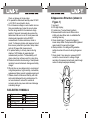
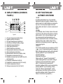
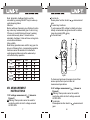
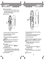
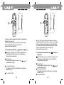
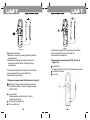
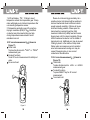
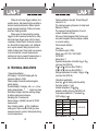
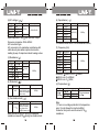
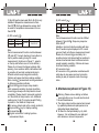
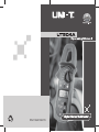
P\N:110401102778
CONTENTS
I. Introduction--------------------------------------------- 1
II.Unpacking Inspection--------------------------------- 1
III.Rules for Safe Operation----------------------------2
IV.Electrical Symbols------------------------------------3
V.Appearance Structure--------------------------------4
VI.Display Symbols-------------------------------------- 5
VII.Key Functions and Automatic Shutdown-------6
VIII.Measurement Instructions------------------------ 7
1.DC Voltage Measurement-------------------------7
2.AC Voltage Measurement-------------------------8
3.Resistance Measurement-------------------------9
4.Diode Measurement------------------------------ 10
5.Conductance Detection-------------------------- 11
6.Capacitance Measurement--------------------- 12
7.Frequency Measurement------------------------13
8.Temperature Measurement--------------------- 14
9.DC Current Measurement-----------------------15
10.AC Current Measurement-----------------------16
IX.Technical Indicators---------------------------------17
X.Maintenance------------------------------------------ 22
I.INTRODUCTION
III.RULES FOR SAFE OPERATION
UT204A is a 3 3/4-bit AC/DC digital clamp
meter (hereinafter referred to as clamp meter )
with stable performance, safety and reliability. As
a special electrician's instrument with excellent
performance, machine circuit is designed on the
basis of large-scale integrated circuit doubleinteger A/D converter with full-range overload
protection circuit and specific appearance design.
Clamp meter can be used to measure AC/DC
voltage, current, resistance, diode,circuit ON/OFF,
capacitance, frequency and temperature, etc.
The usage manual includes related safety
information and warning prompt, etc. Please read
content carefully and abide by all warnings and
notices strictly.
Please pay attention to Warning Sign
and Cautionary Words . Warning refers to
possible danger to user, instrument or measured
equipment.
The instrument shall be designed and
produced according to GB4793 Safety
Requirements of Electronic Measuring Instrument,
IEC 61010-1 and IEC 1010-2-032 Safety Standard
to meet safety standards of duplex insulation, overvoltage CAT II 600V, CAT III 300V and pollution
level
Warning: Please read Rules for Safe
Operation c arefully before usage of c lamp meter.
II.UNPACKING INSPECTION
Please open the package box and take instrument
out. Please check if following items are deficient or
damaged or not.
1. Usage manual
2. Probe
3. Temperature probe
4. Guarantee certificate
1 book
1 pair
1 probe
1 sheet
Please contact your supplier instantly if any item
is deficient or damaged.
Protection ability may be weakened or lost if
failing to use clamp meter according to related
operation instructions.
1. Please inspect clamp meter and probe before
use to avoid damage or abnormal use. Please
do not use the clamp meter again if probe or
shell insulation is damaged obviously with LCD
display failure or clamp meter cannot operate
normally.
2. It is strictly prohibited to use clamp meter before
covering rear cover and battery cell to avoid
electric shock.
3. Fingers cannot exceed probe forehand during
measurement. Do not touch nude electric wires,
connector, unused input end or circuits during
measurement to avoid electric shock.
4. Function switch must be in correct position
before measurement. It is strictly prohibited to
change gears during measurement to avoid
damage of clamp meter.
5. Do not exert at least 600V between terminal of
clamp meter and grounding to avoid electric
Shock or damage of clamp meter.
6. To operate the instrument carefully under DC 60V
or AC 30V to avoid electric shock.
7. Do not measure voltage or current which is more
than permissible input value. Be sure to place
function range switch to the maximum range
position if scope of measured value cannot be
determined. Be sure to cut off circuit power and
discharge all capacitors before ON/OFF
measurement of online resistance, diode or
circuit. To disconnect probe and measured circuit
then remove probe from input end of clamp meter
and cut off power after measurement.
8. To replace battery in a timely manner during
display of LCD display to guarantee high
measurement precision. To take battery out if
clamp meter has not been used for a long time.
9. Please do not alter internal wiring of clamp meter
randomly to avoid instrument damage and safety
danger.
10.Do not store or use clamp meter in environment
in high-temperature, high-humidity, combustible,
explosive and strong current magnetic environment.
11.Please clean the instrument shell by soft cloth
and neutral detergent during maintenance. Do
not use abrasive or solvent to avoid shell
corrosion which may cause instrument damage
and safety danger.
V.Appearance Structure (shown in
Figure 1)
1. Input end;
2. LCD digit display;
3. Function key: To select basic functions;
4. Measurement function knob: White mark is
initially set value; Blue mark is validated after
selecting blue key;
5. Clamp head trigger: To press the trigger to
loosen clamp head. Clamp head will be tightened
again locally if loosening the trigger;
6. Hand protection: It is designed to guarantee
safety when hand of users touching dangerous
zone;
7. Clamp head: It is a device to measure AC/DC
current to convert current to voltage. Single
conductor of measured current must pass through
center of clamp head perpendicularly;
7
6
4
5
3
2
IV.ELECTRIC SYMBOLS
Duplex insulation
Grounding
AC
DC
Deficient battery
Diode
Warning prompt
Buzzing ON/OFF
AC or DC
To meet European Union standard.
1
Figure 1
VI. DISPLAY SYMBOLS (SHOWN IN
FIGURE 2)
5
6 7 8 9 10
11
12
4
3
13
14
15
2
1
16
Figure 2
1. AC signal measurement instructions;
2. Negative polarity instructions;
3. DC signal measurement instructions;
4. Instructions of deficient battery charge;
5. Automatic range instructions;
6. Diode testing instructions;
7. ON/OFF detection instructions;
8. Measurement instructions of duty cycle;
9. Data maintenance instructions;
10. Measurement instructions of relative value;
11. Temperature measurement unit ( );
12. Resistance measurement unit (ohm, kilo-ohm
and mega-ohm);
13. Frequency measurement unit (Hz);
14. Capacitance measurement unit (nF and µF);
15. Current measurement unit (A);
16. Voltage measurement unit (mV and V);
VII. KEY FUNCTIONS AND
AUTOMATIC SHUTDOWN
1.HOLD
As reading maintenance key, it is to maintain
displayed reading by triggering. Displayed value
will be locked for constant display by pressing the
key once. It can be pressed again to release
locking status and return to common measurement
status.
2.REL
Current display value of clamp meter will be used
as reference value after pressing the key. Display
will be reset to 0 to minus reference value
from measurement result automatically until
exiting measurement function of relative value by
pressing the key again. relative range can be
switched over by pressing the key in
and
measurement gears.
3.SELECT
It is a function selection key for switchover of
and measurement gears by triggering.
Note: Automatic shutdown function will be cancelled
if pressing SELECT key for bootstrap after
automatic shutdown.
4.Automatic Shutdown
Clamp meter will power off automatically
(under sleeping status) to save electric energy if
function key and knob switch fail to operate
within 15 minutes during measurement.
Automatic shutdown function can be cancelled by
pressing SELECT key for bootstrap. Clamp
meter will start up automatically (under
working status) by rotating function key under
automatic shutdown status. (Please refer to
Clause 6 for effective key operation.)
Note: Automatic shutdown function will be
cancelled by pressing SELECT key for wake-up
under sleeping status.
5.Buzzer
Buzzer will beep if pressing any effective function
key under any measurement gear. It will not ring
if the key is invalid. Buzzer will issue 5 warning
voices continuously about 1 minute before
automatic shutdown. It also will issue a long-term
voice before shutdown.
6.Key validity
Note all key operations are valid for any gear. As
shown in following form, corresponding operation
functions cannot be selected or instruments
under sleeping status cannot be wakened up
until effective key operation.
Key
SELECT
REL
To set knob.
Please place function knob to
measurement
gear.
To select key functions.
To set measured DC voltage to initially set value.
Initially set automatic range can be set to relative
range by pressing REL key.
To connect load.
V
HOLD
ºì
Hz
N/A
N/A
ºÚ
N/A
Figure 3
To disconnect probe and measured circuit then
remove probe from input end after all
measurement operations.
VIII. MEASUREMENT
INSTRUCTIONS
1. DC voltage measurement ( ) (shown in
Figure 3)
Warning: Clamp meter cannot be used for
conductive article of which voltage exceeds
AC/DC 600V.
2. AC voltage measurement (
) (shown in
Figure 4)
Warning: Clamp meter cannot be used for
conductive article of which voltage exceeds
AC/DC 600V.
* To set knob.
Please place function knob to
measurement
gear.
To select key functions.
To set measured DC voltage to initially set value.
Initially set automatic range can be set to relavite
range by pressing REL key.
To connect load.
~
V
~
ºì
ºì
ºÚ
ºÚ
Figure 5
Figure 4
To disconnect probe and measured circuit then
remove probe from input end after all
measurement operations.
3. Resistance measurement ( ) (shown in
Figure 5)
Warning: Be sure to cut off circuit power and
discharge residual charge of all capacitors
before load connection.
To set knob.
Please place function knob to
measurement gear.
To select key functions.
To set measured DC voltage to initially set value.
Initially set automatic range can be set to relative
range by pressing REL key.
To connect load.
To gain excellent measured result by separating
element from circuit.
To disconnect probe and measured circuit then
remove probe from input end after all
measurement operations.
4. Diode measurement (
) (shown in Figure 6)
Warning: Be sure to cut off circuit power and
discharge residual charge of all capacitors
before load connection.
To set knob.
Please place function knob to
measurement gear.
To select functions.
To select diode detection by pressing SELECT
key;
To connect load.
ºì
Figure 6
) (shown in Figure 7)
Warning: Be sure to cut off circuit power and
discharge residual charge of all capacitors
before load connection.
To set knob.
Please place function knob to
measurement gear.
To select functions.
To select conductance detection by pressing
SELECT key;
To connect load.
ºÚ
Figure 7
To gain excellent measured result by separating
element from circuit.
To disconnect probe and measured circuit then
remove probe from input end after all
measurement operations.
5. Conductance detection (
ºì
ºÚ
Buzzer will ring if measured resistance during
conductance test is less than 10 . It can ring or
not ring if measured resistance exceeds 10 .
To disconnect probe and measured circuit then
remove probe from input end after all
measurement operations.
6. Capacitance measurement ( ) (shown in
Figure 8)
Warning: Be sure to cut off circuit power and
discharge residual charge of all capacitors
before load connection.
To set knob.
Please place function knob to
measurement gear.
To select functions.
To select capacitance detection by pressing
SELECT key;
To connect load.
Hz
ºì
ºì
ºÚ
Figure 9
Figure 8
Measurement notice:
1)Be sure to reset by pressing REL key before
measurement.
2)Instrument reading will delay for about 30
seconds normally when measuring large
capacitance.
To disconnect probe and measured circuit then
remove probe from input end after all
measurement operations.
To disconnect probe and measured circuit then
remove probe from input end after all
measurement operations.
8.Temperature measurement ( ) (shown in
Figure 10)
To set knob.
To place function knob to
To select functions.
To connect load.
7.Frequency measurement (Hz) (shown in Figure 9)
Warning: Clamp meter cannot be used for
conductive article of which voltage exceeds
AC/DC 600V.
To set knob.
Please place function knob to
measurement gear.
To select key functions.
To connect load.
ºÚ
Hz
Figure 10
measurement gear.
1) LCD will display OL if failing to insert
temperature sensor into temperature gear. Clamp
meter will display current indoor temperature after
user inserting temperature sensor.
2) Temperature protection gear of the machine
is plug-in resistance (R59) of 1K . Electrified
conductor cannot be inserted into input jack
during temperature measurement to avoid
resistance burnout.
9. DC current measurement ( ) (shown in
Figure 11)
To set knob.
To place function knob to 40A or 600A
measurement gear.
To select functions.
To set DC current measurement to initially set
value.
To connect load.
A
Figure 11
Please do not loosen trigger suddenly. As a
sensitive device, Hall element will be sensitive to
heat and mechanical stress to different extents
except magnetic sensitivity. Collision will cause
short-term reading variation. Please open the
clamp head by pressing trigger then fetch
measured conductor by clamp head and loosen
trigger slowly until it is closed completely. Please
check if measured conductor is in the middle of
clamp head or not. Additional error may be caused
if failing to place it in the middle of clamp head.
Clamp meter can measure a current conductor
once and measurement reading error may be
caused if measuring two or more current
conductors at the same time.
10. AC current measurement ( ) (shown in
Figure 12)
To set knob.
To place function knob to 40A or 600A
measurement gear.
To select functions.
To press SELECT key for AC current
measurement;
To connect load.
Figure 12
Please do not loosen trigger suddenly. As a
sensitive device, Hall element will be sensitive to
heat and mechanical stress to different extents
except magnetic sensitivity. Collision will cause
short-term reading variation.
Please open the clamp head by pressing
trigger then fetch measured conductor by clamp
head and loosen trigger slowly until it is closed
completely. Please check if measured conductor
is in the middle of clamp head or not. Additional
error may be caused if failing to place it in the
middle of clamp head. Clamp meter can measure
a current conductor once and measurement
reading error may be caused if measuring two or
more current conductors at the same time.
IX. TECHNICAL INDICATORS
1.General specification
LCD display: 3 3/4-bit LCD display with the
maximum display to 3,999;
Polarity display: Automatic positive/negative
polarity display;
Overload display: To display OL or -OL ;
Under-voltage display:
symbol can show
that battery voltage is less than working voltage
for battery replacement reference;
Sampling rate: 3 times/second;
Sensor category: Hall affect sensor for DC/AC
measurement;
Error of testing position: 1.0% of additional
reading error may be caused if failing to place
measured source to center of clamp head during
current measurement;
Collision-resistance strength: To bear falling-off
collision for 1m;
The maximum opening dimension of clamp head:
Diameter of 28mm;
The maximum forecast dimension of current
conduits: Diameter of 26mm;
Influence of electromagnetic field: Device used
near electromagnetic field may display unstable
or incorrect reading;
2.Environment limitation
Indoor use
The altitude height: 2,000m
Safety rules: ICE 1010-1 CAT.II 600V
CAT.III300V
Hazard level: 2
Operation temperature & humidity: 0 to 30
(not more than 80%R.H.)
30 to 40 (not more than 75%R.H.)
40 to 50 (not more than 45%R.H.)
Storage temperature & humidity: -20 to +60
(not more than 80%R.H.)
3.Electrical specification
Accuracy: (& of reading and bit quantity);
Correction period is 1 year;
Ambient temperature: 23
5
Ambient humidity: Not more than 80% R.H.
Temperature coefficient: 0.1*precision/1
(1)DC voltage (
)
Range
400.0mV
4.000V
40.00V
400.0V
600V
Overload protection
Resolution Accuracy
(0.8%+3)
0.1mV
1mV
(0.8%+1)
10mV
600V DC/AC
100mV
(1%+3)
1V
Input impedance: 10M
(2)AC voltage (
Range
4.000V
40.00V
400.0V
600V
)
(6) Capacitance (
Overload protection
Resolution Accuracy
1mV
(1%+5)
10mV
600V DC/AC
100mV
(1.2%+5)
1V
Input impedance: 10M
//not less than 100pF
Frequency response: 40Hz~400Hz
AC conversion type:
AC conversion is to guarantee consistence with
valid value by sine wave input and correction
reading by way of response mode of average value.
(3) Resistance ( )
Range
400.0
4.000K
40.00K
400.0K
4.000M
40.00M
Resolution
100m
1
10
100
1K
10K
(4) Diode test (
Range Resolution
1mV
Accuracy Overload protection
(1.2%+2)
(1%+2)
0.1
Resolution
0.001nF
0.01nF
0.1nF
0.001µF
0.01µF
0.1µF
)
Accuracy
)
Accuracy
Overload protection
To display approximate
positive pressure drop.
(Open circuit voltage is
about 1.48V.)
600Vp
)
Overload protection
Buzzer will ring if it is
less than or equal to
10 . (Open circuit
voltage is about 0.45V.)
600Vp
Note: Buzzer will ring or not ring if measured
resistance exceeds 10 during conductance test.
600Vp
(5.0%+10)
To measure under RELATIVE measurement mode;
(7) Frequency (Hz)
Range
10Hz
100Hz
1kHz
10kHz
100kHz
1MHz
10MHz
Resolution
0.001Hz
0.01Hz
0.1Hz
1Hz
10Hz
100Hz
1kHz
Accuracy
Overload protection
600Vp
(0.5%+3)
(Reading is only for reference.)
100kHz;
(8) Temperature ( )
Range
Accuracy
Overload protection
(4.0%+3)
Sensitivity: 300mV rms if
600mV rms if 100kHz;
800mV rms if 1MHz;
(1.2%+2)
(1.5%+2)
(5) Conductance test (
Range Resolution
600Vp
Range
4nF
40nF
400nF
4µF
40µF
100µF
-40 ~
1,000
Accuracy
(8%+5)
-40 ~0
(2.5%+3)
0 ~400
(3.0%+3)
400 ~1,000
Overload protection
Plug-in resistance
of 1K
Note:
1) There is no voltage protection for temperature
gear. It is not allowed to insert electrified
conductor into jack to avoid burnout of 1K
resistance;
2) Spot K type thermocouple (Ni-Cr~Ni-Si) is only
suitable to temperature measurement of less
than 230 . Rod type temperature sensor shall
be used for temperature measurement of more
than 230 .
(9) AC current (
(9) DC current (
Note:
Current measurement function must be fulfilled
between 0 and 40 . Frequency response:
50Hz~60Hz;
Instable or incorrect inductive reading with less
than 10 words may be displayed in AC current
gear and it will not influence measurement result.
Please do not loosen trigger suddenly. As a
sensitive device, Hall element will be sensitive to
heat and mechanical stress to different extents
except magnetic sensitivity. Collision will cause
short-term reading variation.
AC conversion type:
AC conversion is to guarantee consistence with
valid value by sine wave input and correction
reading by way of response mode of average
value.
Range
40.00A
600A
)
Resolution
0.01A
1A
Accuracy
(2%+5)
Overload protection
600A DC/AC
Note:
Current measurement function must be between
0 and 40 . Current direction is from bottom to
top for positive reading during DC current
measurement. (As shown in Figure 11, panel is
on the top and bottom cover is on the bottom.)
Please do not loosen the trigger suddenly after
pressing. As a sensitive device, Hall element will
be sensitive to heat and mechanical stress to
different extents except magnetic sensitivity.
Collision will cause short-term reading variation.
More correct
measurement can be guaranteed
by following operation methods:
Press the trigger and open clamp head to
fetch measured conductor by clamp head then
loosen trigger slowly until clamp head is closed
completely. Please check if measured conductor
is in the middle of clamp head or not. Additional
reading error of 1.0% may be caused if failing
to place it in the middle of clamp head;
To remove clamp head on the current conductor;
To press REL key for display resetting;
To repeat step ;
To gain more correct reading by above
measurement steps;
)
Range Resolution Accuracy
40.00A 0.01A
600A 1A
Frequency
response
Overload
protection
(2.5%+8)
50Hz~60Hz 600A DC/AC
(2.5%+5)
X. Maintenance(shown in Figure 13)
Warning: Please remove testing rod before
opening bottom cover to avoid electric shock.
1. General maintenance
A. The clamp meter must be repaired and served
by qualified professional repair personnel or
designated repair department.
B. To clean the shell periodically by dry cloth.
However, it is not allowed to use detergent
with abrasive or solvent components
Figure 13
2: Battery installation or replacement
1 6F22 9V battery shall be supplied for the
product. Please install or replace the battery by
following sequence:
a. Please remove testing rod in the input end
during shutdown.
b. To let panel face downwardly, loosen screws
on the cell box, extract cell cover then remove
cell box.
c. To remove old battery from cell box for
installation of new battery according to polarity
instructions.
d. Please use the same model of battery. Please
do not install improper battery.
e. To install cell cover and lock screws after
installation of new battery.