1
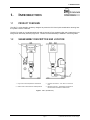
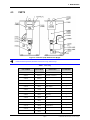
Self Purging Liquid Trap
(SPLT™)
User’s Manual
© 1998-2009 DH Instruments, a Fluke Company
High pressure liquids and gases are potentially hazardous. Energy stored in these liquids and gases can be
released unexpectedly and with extreme force. High pressure systems should be assembled and operated
only by personnel who have been instructed in proper safety practices.
© 1998 - 2009 DH Instruments, a Fluke Company All rights reserved
Information in this document is subject to change without notice. No part of this document may be reproduced or transmitted in any form or
by any means, electronic or mechanical, for any purpose, without the express written permission of DH Instruments 4765 East Beautiful
Lane Phoenix AZ 85044-5318 USA.
DH Instruments, a Fluke Company makes sincere efforts to ensure accuracy and quality of its published materials; however, no warranty,
expressed or implied, is provided. DH Instruments, a Fluke Company disclaims any responsibility or liability for any direct or indirect
damages resulting from the use of the information in this manual or products described in it. Mention of any product does not constitute an
endorsement by DH Instruments of that product. This manual was originally composed in English and was subsequently translated into
other languages. The fidelity of the translation cannot be guaranteed. In case of conflict between the English version and other language
versions, the English version takes precedence.
DH Instruments, a Fluke Company, DH , DHI, PPC, PPC2, PPC3, PPC, and PPC2 AF are trademarks, registered and otherwise.
090629
3152142
Printed in the USA.
© 1998-2009 DH Instruments, a Fluke Company
TABLE OF CONTENTS
TABLE OF CONTENTS
TABLE OF CONTENTS .................................................................. I
TABLES ..................................................................................... II
FIGURES .................................................................................... II
ABOUT THIS MANUAL ................................................................ III
1.
2.
INTRODUCTION..................................................................... 1
1.1
PRODUCT OVERVIEW....................................................................................................................................... 1
1.2
1.3
SUBASSEMBLY DESCRIPTION AND LOCATION........................................................................................... 1
SPECIFICATIONS............................................................................................................................................... 2
INSTALLATION ..................................................................... 3
2.1
2.2
3.
OPERATION .......................................................................... 5
3.1
4.
PNEUMATIC........................................................................................................................................................ 3
ELECTRICAL ...................................................................................................................................................... 4
GENERAL OPERATING INSTRUCTIONS......................................................................................................... 5
MAINTENANCE...................................................................... 7
4.1
4.2
4.3
GENERAL............................................................................................................................................................ 7
REMOVING AND INSTALLING THE SPLT FILTER.......................................................................................... 7
SPLT EXHAUST VALVE REMOVAL AND REPLACEMENT............................................................................ 8
4.4
4.5
OVERHAUL ......................................................................................................................................................... 8
PARTS ................................................................................................................................................................. 9
Page I
© 1998-2009 DH Instruments, a Fluke Company
SPLT™ USER’S MANUAL
TABLES
Table 1. Parts Listing ........................................................................................................................................... 9
FIGURES
Figure 1. SPLT (Overall View) ............................................................................................................................. 1
Figure 2. PPC with SPLT and DUT...................................................................................................................... 3
Figure 3. Front View (Left) and Side View (Right)................................................................................................ 9
© 1998-2009 DH Instruments, a Fluke Company
Page II
ABOUT THIS MANUAL
ABOUT THIS MANUAL
Manual Conventions
(CAUTION) is used in manual to identify user warnings and cautions.
(NOTE) is used in the manual to identify operating and applications advice and additional explanations.
Page III
© 1998-2009 DH Instruments, a Fluke Company
SPLT™ USER’S MANUAL
NOTES
© 1998-2009 DH Instruments, a Fluke Company
Page IV
1. INTRODUCTION
1.
INTRODUCTION
1.1
PRODUCT OVERVIEW
The SPLT is a free standing accessory designed to protect the PPC from liquid contamination returning from
the system or device under test.
The SPLT is made up of a stainless steel body with an internal X-Type coalescing filter and a bottom drain port
fitting with an electrically actuated purge valve. The filter and valve assembly is installed in a mounting stand.
1.2
SUBASSEMBLY DESCRIPTION AND LOCATION
1. Purge Tube - Exhaust liquids and contaminants
3. Pressure Connections – 1/4 in. NPT F to test and to
PPC
2. Exhaust Valve - Solenoid valve to release pressure
4. Electrical Connection - Terminal block connections to
PPC valve driver for activation of exhaust valve
Figure 1. SPLT (Overall View)
Page 1
© 1998-2009 DH Instruments, a Fluke Company
SPLT™ USER’S MANUAL
1.3
SPECIFICATIONS
Pressure Connections
1/4 in. NPT F
Power Requirements
Apply 12 V to actuate valve, 6 watts
Weight
1.7 kg (3.8 lb)
Dimensions
10 cm H x 10 cm W x 17.5 cm D (3.9 in. x 3.9 in. x 6.9 in.)
Maximum Working Pressure
1 500 psi
Maximum Differential Across Filter
80 psi
Operational Capacity of Filter Body
10 cc
© 1998-2009 DH Instruments, a Fluke Company
Page 2
2. INSTALLATION
2.
INSTALLATION
2.1
PNEUMATIC
Figure 2. PPC with SPLT and DUT
Be sure SPLT is at low point of pneumatic system.
The SPLT is intended to collect and exhaust liquid contaminants that may be present in the device or system
under test so that they do NOT return to the PPC.
The SPLT is installed in the test connection line at a low point between PPC and the device or system under
test. The SPLT pressure connections are 1/4 in. NPT female.
Teflon™ tape or another sealing material should be used to assure leak free connection of adaptors
installed in the SPLT pressure connections.
Proper SPLT operation is dependent on the gas flowing through it in the correct direction. Make sure to connect
the SPLT to the device or system under test and the PPC following the connector port labels on the SPLT.
Connect the SPLT electrically to the PPC rear panel DRIVER connection and to the SPLT terminal block (see
Section 2.2).
The SPLT must be mounted vertically with the purge valve at the bottom to perform properly. The SPLT MUST
be at a lower point in the system than the PPC and/or the device under test. In operation, liquid contaminants
collected from the device or system under test will be exhausted through the SPLT purge valve.
Page 3
© 1998-2009 DH Instruments, a Fluke Company
SPLT™ USER’S MANUAL
Liquid contaminants will be forcibly ejected from the SPLT purge tube. Provision for collecting the purged
liquids should be considered when installing the SPLT.
Excessively dirty or wet filter elements can adversely affect pressure control.
2.2
ELECTRICAL
In order to take advantage of the automatic purging feature of the PPC, the SPLT valve MUST be connected to
the PPC external driver #8.
Connect like this if drivers connector with attached cable was included with SPLT:
Connect drivers connector to DRIVERS connector on back panel of PPC. Attach the two wires to the
terminal block on the SPLT
Connect like this if you have SPLT without drivers connector:
Solder (2) 24 gauge wires of desired length to the 12-pin connector provided with the PPC. Connect
(1) wire to pin L and the other to pin B. Connect drivers connector to DRIVERS connector on back
panel of PPC. Attach the other end of these wires to the terminal block on the SPLT.
Polarity is NOT significant to the operation of the purge valve.
© 1998-2009 DH Instruments, a Fluke Company
Page 4
3. OPERATION
3.
OPERATION
3.1
GENERAL OPERATING INSTRUCTIONS
See the section on Installing a Self Purging Liquid Trap in the PPC Operation and Maintenance manual.
Page 5
© 1998-2009 DH Instruments, a Fluke Company
SPLT™ USER’S MANUAL
NOTES
© 1998-2009 DH Instruments, a Fluke Company
Page 6
4. MAINTENANCE
4.
MAINTENANCE
4.1
GENERAL
The maintenance of the SPLT consists of cleaning or replacing the internal coalescing filter. A dirty filter should
be rinsed with a degreasing agent to remove oil and particulate matter. A filter with physical damage should be
replaced.
4.2
REMOVING AND INSTALLING THE SPLT FILTER
See Section 4.5 for part number and figures referred to in the filter replacement procedure.
Remove power and pressure connections prior to disassembly.
The procedure for replacing the coalescing filter in the SPLT is as follows:
Disconnect pressure tubing to the SPLT if necessary.
Disconnect power leads to the exhaust valve solenoid (3137053).
Disconnect drain tube (3232357) from elbow adaptor (3133040).
Unscrew lower housing of filter using flats on the lower housing.
Lower the housing with attached valve and fittings through the slot in the mounting bracket.
Remove filter, clean cavity (3136996).
Install new filter.
Re-assemble SPLT.
Leak Check.
Page 7
© 1998-2009 DH Instruments, a Fluke Company
SPLT™ USER’S MANUAL
4.3
SPLT EXHAUST VALVE REMOVAL AND REPLACEMENT
See Section 4.5.
•
Disconnect pressure tubing to the SPLT.
•
Disconnect power leads to the exhaust valve solenoid (3137053).
•
Remove solenoid valve from SPLT body (3136996).
•
Remove fittings (3137066, 3133040) and drain tube (3232357) from exhaust valve.
•
Install fittings (3137066, 3133040) and drain tube (3232357) onto the new exhaust valve.
•
Reinstall exhaust valve onto SPLT body (3136996).
•
Leak check assembly.
Any or all of the following items may be included as part of SPLT maintenance and overhaul:
•
Clean or change filter (see Section 4.1).
•
Clean internal portions of SPLT body using a degreasing agent.
•
Check exhaust valve solenoid power leads.
•
Check tightness of fittings on SPLT exhaust solenoid valve.
•
Check drain tube and replace as necessary.
4.4
OVERHAUL
Any or all of the following items may be included as part of SPLT maintenance and overhaul:
•
Clean or change filter (see Section 4.1).
•
Clean internal portions of SPLT body using a degreasing agent.
•
Check exhaust valve solenoid power leads.
•
Check tightness of fittings on SPLT exhaust solenoid valve.
•
Check drain tube and replace as necessary.
© 1998-2009 DH Instruments, a Fluke Company
Page 8
4. MAINTENANCE
4.5
PARTS
Figure 3. Front View (Left) and Side View (Right)
Unless otherwise specified, Seal NPT Connections using Teflon™ tape.
Table 1. Parts Listing
PART NUMBER
PREVIOUS DHI
PART NUMBER
2678004
100970-Z
Hex nut, M 3
1
3232357
101392-Z
Drain tube, 1/8 in. O.D.
1
3153533
102088-Z
Split lock washer
2
3153741
102461-Z
Label
1
3115728
122587-Z
Label
1
3133040
100321
Elbow adaptor
1
3133921
101008
Allen screw, M3 X 20
1
3134409
101468
Rubber grommet
6
3136981
102501
Liquid trap
1
3136996
102502
Filter
1
3137053
102514
12 VDC solenoid valve
1
3137066
102516
Reducer, adaptor
1
3137142
102528
Terminal block
1
3137156
102530
Allen screw, 1/4-20 X 1/2
2
3146329
122541
Mounting bracket
1
DESCRIPTION
Page 9
QTY REQUIRED
© 1998-2009 DH Instruments, a Fluke Company
SPLT™ USER’S MANUAL
NOTES
© 1998-2009 DH Instruments, a Fluke Company
Page 10