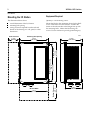
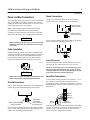
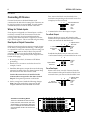
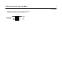
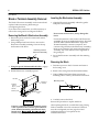
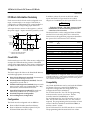
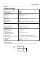
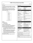
1
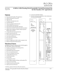
I/OProducts
NEMA4 I/O Station
GFK–0832A
June 1994
IC66*BXD022
The NEMA4 I/O Station consists of a 24 VDC Source
I/O block installed in a rugged aluminum NEMA4
housing. The block is pre-wired to receptacles in the
housing, for simple connection of field wiring.
ÎÎ
GENIUS
Block Features
24/48 VDC
Source In/Out
GE Fanuc
The block in the I/O Station can be used with 2–wire
and 3–wire solid state sensors and electromechanical
sensors. It has 16 discrete circuits, each easily
configured to be an input, tristate input, or output.
Output circuits can be connected directly to input
circuits without the use of other components or
inversion of logic states.
The block’s LEDs verify proper block operation and CPU
communications. Individual circuit LEDs on the logic side
indicate voltage present on inputs and outputs.
Housing Features
The I/O Station’s NEMA4 housing provides a measure
of protection against falling, splashed, and
hose-directed water. It can be used indoors or
outdoors. The block will not be damaged by the
formation of ice on the housing.
I/O connections to the block are made through the
housing via Brad Harrison -style molded receptacles.
Communications and power cables are installed via
pass-through water-tight connectors.
t
The housing has a transparent window in the cover so
the block’s LEDs can be seen.
ÎÎ
ÎÎ
ÎÎÎÎÎ
ÎÎ
ÎÎÎÎ
ÎÎÎ
ÎÎ
ÎÎ
a45351
Using this Datasheet
This datasheet describes installation of the I/O Station. It
also briefly summarizes information about the operation,
configuration, and diagnostics features of the I/O block.
If you need more information about the I/O block, please
see the Discrete and Analog Blocks User’s Manual
(GEK-90486-2). For information about systems and
communications, including bus specifications, refer to
the System and Communications Manual (GEK-90486-1).
2
NEMA4 I/O Station
GFK-0832A
Mounting the I/O Station
Equipment Required
The illustration below shows:
Quantity 4: #10 mounting screws
H
H
H
Mount the block in the orientation shown below. Drill
screw or bolt holes for #10 hardware. Position the
station so that the notches in the flanges line up with
the mounting holes. Mount the block using #10
screws. Use star washers to provide ground integrity.
overall dimensions of the I/O Station
mounting hole spacing
wiring clearances required from the side and
bottom of the housing to a wall, panel, or other
obstruction.
a45353
Mounting Hole Spacing
7.31 in
(185.7mm)
Module Width
7.13 in
(181.1mm)
Module Height
10.13 in
(257.3mm)
Bottom Clearance
3.70 in
(94mm)
ÎÎÎÎÎ
ÎÎÎÎÎ
ÎÎÎÎÎ
ÎÎÎÎÎ
ÎÎÎÎÎ
ÎÎÎÎÎ
ÎÎÎÎÎ
ÎÎÎÎÎ
ÎÎÎÎÎ
ÎÎÎÎÎ
ÎÎÎÎÎ
ÎÎÎÎÎ
ÎÎÎÎÎ
ÎÎÎÎÎ
Î
Î
5.50 in
(139.70mm)
Mounting Hole Spacing
8.88 in
(225.6mm)
Side Clearance
2.70 in
(68.6mm)
4.28 in
(108.7mm)
NEMA4 16 Circuit DC Source I/O Block
3
GFK-0832A
Power Connections
Power and bus cables must be 0.25” to 0.375” in diameter.
The power cable must include a ground wire, to bring
chassis ground into the module. Three to six .250” x .032”
female quick disconnects are required.
Using two quick disconnects, attach the incoming
power wires to the wiring board as shown below.
Note: The I/O Station can be located on a bus stub
downstream of another device that performs bus
switching. It cannot be directly connected to a dual bus.
Attach incoming
+24V wire here
COM
+24V
Power and Bus Connections
Attach incoming
common wire here
Remove the housing cover to begin cable installation.
Caution
Pass the incoming serial bus and power cables through
connectors SI and PI on the housing bottom. Connectors
SO and PO can be used to daisy-chain the bus and/or
power cable to another device. To use either of these
connectors, first loosen the nut and remove the plug.
ÎÎÎ
a45352
Plug
Caution
Tighten the connector nuts firmly around all bus and
power cables before completing the installation.
GroundConnections
Using a quick disconnect, attach the power cable ground
wire to the ground terminal near the wiring board:
Attach optional outgoing
ground wire here
Ground wire
to I/O block
Attach incoming
ground wire here
If you are daisy-chaining the power cable out to another
device, connect the ground wire of the outgoing power
cable to the remaining ground terminal.
COM
Attach outgoing +24V wire
here
Cable Installation
+24V
After installation, the housing cover must be firmly
installed on the base. Recommended screw torque
is 12 in/lbs.
If you are daisy-chaining the power cable out to another
device, connect the outgoing power wires.
Attach outgoing common wire here
Power Disconnects
Wire external power disconnects so that block power
and input power will be removed at the same time.
Caution: If circuit power is not removed at the same
time as block power, the block may power up when
multiple inputs are activated, even though one leg of
power has been removed from the block.
Serial Bus Connections
Connect the incoming serial bus to terminals 1 – 3 on
the I/O block, as shown below. If there is also an
outgoing bus cable, connect it to terminals 1, 2, and 4.
Recommended torque for the terminal screws is 6 in/lb
(.678N/M).
ÎÎÎ
ÎÎ
ÎÎÎ
ÎÎ
ÎÎÎ
ÎÎ
ÎÎ
ÎÎ
ÎÎÎ
ÎÎ
Î
1
2
3
4
Serial
Bus In
SERIAL 1
SERIAL 2
SHIELD IN
SHIELD OUT
Optional
Serial Bus Out
If the station is at the end of the bus (no bus out cable),
connect a terminating resistor of the appropriate type
(see the System and Communications User’s Manual)
across its Serial 1 and Serial 2 terminals.
4
NEMA4 I/O Station
GFK-0832A
Connecting I/O Devices
First, remove the black wire from the In/Out
terminal corresponding to the unused circuit. For
example (if 9 were not used):
Connect I/O devices to the Brad Harrison-style
connectors in the side of the housing. Each connector can
be used for an input or output. Note: To avoid possible
contamination, leave covers on unused connectors.
7
remove black wire
9
IN/OUT
COM
N.C.
+24V
Wiring for Tristate Inputs
If any input is configured as a Tristate Input, it will be
necessary to install a 1.6K ohm resistor across that
circuit’s input and +24 volt terminals (inside the
housing). This added resistance is required to use the
Open Wire diagnostic. The circuit LED will glow dimly.
5. Continue below for a dual output or input.
For a Dual Output:
Remove the brown wire (+ 24V) from the other
terminal of the pair. Install it on the In/Out terminal
where you removed the first black wire.
Dual Input or Output Connection
7
Dual input and output devices require a simple change
to the factory wiring inside the housing. A dual input
or output device uses one connector in the housing, but
counts as two circuits on the I/O block. For practical
purposes, these two circuits should be located near
each other on the wiring board (see the diagram at the
bottom of the page).
9
IN/OUT
COM
N.C.
1. remove
brown wire
here
+24V
Install the first (black) wire you removed on the
+ 24V terminal where you removed the brown wire:
7
1. Be sure power to the I/O Station is OFF before
proceeding.
9
IN/OUT
COM
N.C.
replace black
wire here
2. Decide on two circuits to use for the device. For
example, 7 and 9.
3. Install the dual input or output device at the housing
connector for either of the two selected circuits. Keep
the connector for the other circuit covered.
2. replace brown
wire here
+24V
For a Dual Input:
Remove the white wire (No Connect) from the
other terminal of the pair. Install it on the In/Out
terminal where you removed the first black wire.
Caution: Be sure no device is installed on the
connector that corresponds to the other circuit of
the pair. Unexpected operation would result.
7
4. On the wiring board, make the following changes.
Note: Using long-nose pliers, grasp wires by the
crimped terminal in the strain relief area ONLY.
9
2. replace white
wire here
IN/OUT
COM
N.C.
1. remove
white wire here
+24V
1
3
5
7
9
11 13 15
Terminals on the Wiring Board
IN/OUT
COM
N.C.
There are 4 terminals for each I/O circuit:
In/Out, Common, No Connect, and +24V.
+24V
+24V
All terminals in a row have the same function. For example, the In/Out terminals for
even-numbered circuits 2 to 16 are in the
same row.
N.C.
COM
IN/OUT
2
4
6
8
10 12 14 16
NEMA4 16 Circuit DC Source I/O Block
5
GFK-0832A
Install the first (black) wire you removed on the NC
terminal where you removed the white wire.
7
replace black
wire here
9
IN/OUT
COM
N.C.
+24V
6
NEMA4 I/O Station
GFK-0832A
Block or Terminal Assembly Removal
Inserting the Electronics Assembly
The block’s Electronics Assembly can be removed and
replaced without removing field wiring or
reconfiguring the block.
1. Align the Electronics Assembly within the guides
and push it down firmly.
Caution
If you remove the entire block, it will be necessary to
remove the wiring and to reconfigure the block.
Removing the Block’s Electronics Assembly
Do not exert excessive force; it may damage the
block.
1. Disconnect power to the I/O station and remove
the housing cover.
If unusual resistance is met, remove the Electronics
Assembly. If power is applied to the block, DO NOT
TOUCH THE CONNECTOR PINS! Inspect the
Terminal Assembly, connector receptacle, and
connector edge board (on the Electronics Assembly).
Remove any obstacles and reinsert the Electronics
Assembly. Pay close attention to the alignment of
the guide pins.
2. Using a Phillips-head screwdriver, unscrew the
Electronics Assembly retaining screws at the top
and bottom of the block.
Retaining screw for
Electronics Assembly
ÎÎ
ÎÎ
ÎÎÎÎ
2. Secure the Electronics Assembly with the retaining
screws.
(top of block)
Removing the Block
3. Using the special I/O Station Block Puller , engage
the tabs in the first vent slots.
1. Disconnect power to the I/O station and remove
the housing cover.
2. Remove the wiring from the Terminal Assembly.
4. Pull the Electronics Assembly upward.
3. Using a Phillips-head screwdriver, unscrew the
mounting screws at the top and bottom of the block.
Vent Slots
Retaining
Screws
(Qty. 2)
Terminal
Assembly
Î
Î
Î
Î
Î
Î
Electronics
Assembly
Mounting screw
ÎÎ
ÎÎ
ÎÎÎÎ
(top of block)
Connector
Pins
Warning
If power is applied to the field terminals, power
is also exposed on the connector pins at the base
of the Terminal Assembly, and electrical shock
hazard exists. Death or injury may result.
4. Carefully remove the block.
Reverse the procedure to replace the block .
After replacing the block, re-install the wiring. Wiring
follows standard color code convention. The block
must be reconfigured (see next page for a brief
explanation) before it can operate on the
communications bus.
NEMA4 16 Circuit DC Source I/O Block
7
GFK-0832A
I/O Block Information Summary
Each circuit on the I/O block can be configured as an
input, a tristate input, or an output. If the block is
configured as a combination block, output feedback is
provided via the corresponding input references.
All output devices connect to the negative (–) side of
the power supply. Inputs control the positive (+) side.
A
DC+
Configured
as an
Intput
Input
Device
75V
A
1–16
I/O
Configured
as an
Output
"
Smart
Switch Processor
*
.1µfd
LED
1200Ω
A
Terminal
Assembly
DC–
Electronics
Assembly
5.6K ohms for 24/48 VDC blocks.
1.8K ohms for 24 VDC blocks
Circuit LEDs
Each circuit has its own LED. If the circuit is configured as
an input, the LED indicates the presence of threshold
voltage at the input terminal. If the circuit is configured as
an output, the LED indicates the actual state of the load.
Diagnostics
The block reports all faults to the Hand–held Monitor,
and takes appropriate corrective action.
H
H
H
H
H
H
Short Circuit Diagnostic (standard) Instantaneous
current exceeds 10 amps at turn–on.
Overtemperature Diagnostic (standard) Internal
temperature exceeds 100º C.
Failed Switch Diagnostic (standard) Output switch
state is not the same as its commanded state.. May
also indicate certain internal block faults.
Open Wire Diagnostic (standard) Electrical (not
mechanical) malfunction on a tristate input.
Overload Diagnostic (configurable)
No Load Diagnostic (configurable)
Configuration
The block must be configured with an HHM to:
H
H
Warning
– Explosion Hazard – DO NOT connect a Handheld Monitor to the block during operation in a
CSA Class 1 Div 2 location.
The features below can be configured from an HHM
(see the Discrete and Analog Blocks User’s Manual for
instructions) or the application program (as detailed in
the System and Communications User’s Manual).
Configurable
Feature
Output
Device
DC–
Field
Connections
*
DC+
In addition, unless all circuits on the block will be
inputs, the Block I/O Type must be set to either
Outputs or Combination on the Program Block ID screen.
Enter its Block Number (serial bus address).
Enter its Reference Number (required only for
IC550 and IC600 series PLCs only).
Circuit
or
Block
Selection
Factory
Setting
Block I/O Type
B
inputs, outputs, combination
inputs
Baud Rate
B
153.6st,153.6ex, 76.8, 38.4 Kb
153.6st
Pulse Test
B
enabled/disabled
enabled
Input Filter Time
B
5–100mS
20mS
Circuit I/O Type
C
input, output, tristate input
input
Report Faults
C
yes/no
yes
Hold Last State
C
yes/no
no
Output Def. State
C
on, off
off
Detect No Load
C
yes/no
yes
Overload S’down
C
yes/no
yes
BSM Present
B
yes/no
no
Outputs Def. Time
B
2.5/10seconds
3 bus scans
Redundancy Mode
B
none, duplex, standby, GMR
none
Duplex Default
B
on/off
off
Config. Protect
B
enabled/disabled
disabled
Note: If the block is configured offline, it must be properly
grounded and have a 75W resistor installed across its Serial
1 and Serial 2 terminals. See the Discrete and Analog Blocks
User’s Manual for instructions.
Compatibility
Any Hand–held Monitor can be used with the NEMA4
I/O Station. However, version IC66*HHM501 is
required to change baud rate configuration, or to
configure the block for redundancy.
For an IC697 series PLC, the CPU and programming
software must be version 2.0 or later. The bus
controller must be IC697BEM731C or later.
For an IC600 series PLC, the CPU must be rev. 105 or
later. For an IC66* series Plus PLC, rev. 110 or later is
required. The programming software must be rel. 4.02
or later. If the bus controller is model IC66*CBB900, it
must be version C or later.
For an IC550 series PLC, the CPU must be rev. 3.0 or later.
The programming software must be rel. 2.01 or later.
8
NEMA4 I/O Station
GFK-0832A
I/O Station Specifications
Catalog Numbers:
NEMA4I/OStation
IC66*BDX022
IC66*BBD022
IC66*TBD022
IC66*EBD020
24VDC Source 16 Circuit Source I/O Block
Terminal Assembly only
Electronics Assembly only
I/O Station Size (height x width x depth)
LEDS (block)
LEDs (each circuit)
Heat Dissipation
Block to Block Isolation
10.13 in (257.3 mm) x 7.63 in (193.8 mm) x 5.50 in (139.7 mm)
Unit OK, I/O Enabled
Individual load side indicators
tbd
1500 V
Operating voltage
Ripple (maximum)
Required DC power
Power supply dropout time
Pass–through current
18–56 VDC (24/48 V), 18–30 VDC (24 V)
10%
150mAtypical/300mAmaximum
10mS
15 Amps, minus the power used by the I/O block and the devices connected to the
I/OStation.
Input Characteristics:
For standard input, voltage relative to (DC–)
Input ON: 16–24 VDC
Input OFF: 0–7 VDC
5.6K ohms (24/48V), 1.8K ohms (24V)
1.7mS (plus selectable filter delay)
5–100mS
Open wire, Overtemperature, Failed Switch
Input processing time (typical)
Input impedance (typical)
Selectable input filter times
Input diagnostics
Output Characteristics:
Output current (steady state)
Maximum inrush current
Block output current
Output OFF leakage current
Maximum switching frequency
Output turn–on delay (maximum)
Output voltage drop
Minimum Recommended Load
Output Diagnostics
2 amps per circuit
10 amps up to 10mS
15 amps at 35C
1.0 mA
Once per second (high inrush current)
1mS
2.0 volts maximum at 2 amps inrush
50 mA with No Load nabled
Short Circuit, Overload, No Load, Failed Switch, Overtemperature
Environmental:
Operating temperature
Storage temperature
Humidity
Vibration
tbd
–40 to +100C (–40 to +212F)
NEMA enclosure
5–10Hz 0.2” (5.08mm) displacement, 10–200Hz at 1G
Temperature Derating
The illustration below shows total load current versus temperature derating for the NEMA4 I/O Station.
Total
Station
Load
Current
(Amps)
16
12
8
4
0
0 10 20 30 40 50 60
Operating Ambient Temperature: Degrees C