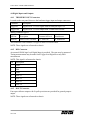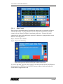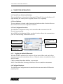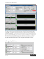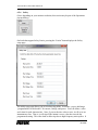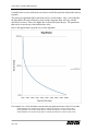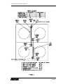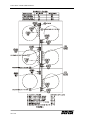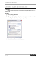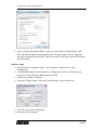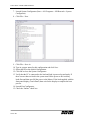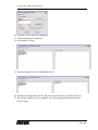
1
® E stablished 1981 Advanced Test Equipment Rentals www.atecorp.com 800-404-ATEC (2832) 4700 LXI DC Load Family User Manual Part No. 09-0299 REVISION K Jan 9, 2014 4700 LXI DC LOAD USER MANUAL Rev X1 Rev A Rev B Rev C Rev D Rev E Rev F Rev G Rev H Rev J Rev K 2 of 103 Document History Preliminary Updated to include PowerTouch Add new safety limits ECO 16813 ECO 16880 ECO 16975 ECO 16983 ECO 16880 ECO 17074 ECO 17109 ECO 17183 9/10/09 3/12/10 1/20/11 6/27/11 3/08/12 5/04/12 5/21/12 8/17/12 1/8/13 3/29/13 1/09/14 C.A.R. R.W. R.W. T.C.F. B.L. T.C.F. T.C.F. K.F. K.F. B.L. S.M 4700 LXI DC LOAD USER MANUAL Proprietary Rights Notice This document and the information that it contains are the property of NH Research, Incorporated. The rights to duplicate or otherwise copy this document, the rights to disclose the document and its information to others, and the right to use the information therein may be acquired only by written permission signed by a duly authorized officer of NH Research, Incorporated. Unauthorized duplication of software and documentation provided with the test workstations violates the copyright protection provided by law. However, backup copies of programs are permitted for archives and recovery from hardware failures. The material in this publication is current as of the release date on the cover page and is subject to change without notice. Any questions concerning the product or any questions or comments concerning this manual should be directed to the NH Research Field Service Department during normal business hours Monday through Friday at (949) 474-3900 or FAX (949) 474-7062 or www.nhresearch.com. emPower is a trademark of NH Research, Incorporated. 3 of 103 4700 LXI DC LOAD USER MANUAL 4 of 103 4700 LXI DC LOAD USER MANUAL TABLE OF CONTENTS 1. 1.1 SAFETY ............................................................................................................................................. 10 WARNING: LIVE CIRCUITS ............................................................................................................ 10 2. 2.1 2.2 2.3 2.4 2.5 2.6 2.7 2.8 2.9 2.10 2.11 2.12 2.13 2.14 2.15 2.16 2.17 2.18 2.19 2.20 2.21 2.22 DESCRIPTION .................................................................................................................................. 11 MODEL VARIATION .............................................................................................................................. 11 4700 LXI LOAD FAMILY COMMON FEATURES ..................................................................................... 11 4700 LXI LOAD - 1KW FEATURES ....................................................................................................... 12 4700 LXI LOAD - 2KW FEATURES ....................................................................................................... 12 4700 LXI LOAD - 3KW FEATURES ....................................................................................................... 12 4700 LXI LOAD - 6KW FEATURES ....................................................................................................... 12 4700 LXI LOAD - 9KW FEATURES ....................................................................................................... 12 4700 LXI LOAD - 12KW FEATURES ..................................................................................................... 12 4700 LXI LOAD – 18KW FEATURES .................................................................................................... 13 4700 LXI LOAD - 24KW FEATURES............................................................................................... 13 4700 LXI LOAD - 30KW FEATURES............................................................................................... 13 4700 LXI LOAD - 36KW FEATURES............................................................................................... 13 4760 LXI LOAD - 1KW FEATURES................................................................................................. 14 4760 LXI LOAD - 2KW FEATURES................................................................................................. 14 4760 LXI LOAD - 3KW FEATURES................................................................................................. 14 4760 LXI LOAD - 6KW FEATURES................................................................................................. 14 4760 LXI LOAD - 9KW FEATURES................................................................................................. 14 4760 LXI LOAD - 12KW FEATURES............................................................................................... 14 4760 LXI LOAD - 18KW FEATURES............................................................................................... 15 4760 LXI LOAD - 24KW FEATURES............................................................................................... 15 4760 LXI LOAD - 30KW FEATURES............................................................................................... 15 4760 LXI LOAD - 36KW FEATURES............................................................................................... 15 3. 3.1 3.2 3.3 3.4 3.5 3.6 3.7 3.8 3.9 3.10 3.11 3.12 3.13 3.14 3.15 3.16 3.17 3.18 3.19 3.20 3.21 3.22 3.23 3.24 SPECIFICATIONS ........................................................................................................................... 17 CONFIGURATION................................................................................................................................... 17 SIZES .................................................................................................................................................... 17 WEIGHT ................................................................................................................................................ 17 COMMUNICATION ................................................................................................................................. 17 PROGRAM CONTROL ............................................................................................................................. 18 ROBUSTNESS ........................................................................................................................................ 18 ISOLATION ............................................................................................................................................ 18 CALIBRATION ....................................................................................................................................... 18 SELF-TEST ............................................................................................................................................ 18 PERFORMANCE MONITORING ......................................................................................................... 18 TEMPERATURE ............................................................................................................................... 19 REMOTE SENSE .............................................................................................................................. 19 SUPPLY POWER .............................................................................................................................. 19 MACROS ......................................................................................................................................... 19 4700 LXI 1KW CONFIGURATION PROGRAMMABLE FEATURES ..................................................... 20 4700 LXI 1KW CONFIGURATION MEASUREMENTS ....................................................................... 20 4700 LXI 2KW CONFIGURATION PROGRAMMABLE FEATURES ..................................................... 21 4700 LXI 2KW CONFIGURATION MEASUREMENTS ....................................................................... 21 4700 LXI 3KW CONFIGURATION PROGRAMMABLE FEATURES ..................................................... 22 4700 LXI 3KW CONFIGURATION MEASUREMENTS ....................................................................... 22 4700 LXI 6KW CONFIGURATION PROGRAMMABLE FEATURES ..................................................... 23 4700 LXI 6KW CONFIGURATION MEASUREMENTS ....................................................................... 23 4700 LXI 9KW CONFIGURATION PROGRAMMABLE FEATURES ..................................................... 24 4700 LXI 9KW CONFIGURATION MEASUREMENTS ....................................................................... 24 5 of 103 4700 LXI DC LOAD USER MANUAL 3.25 3.26 3.27 3.28 3.29 3.30 3.31 3.32 3.33 3.34 3.35 3.36 3.37 3.38 3.39 3.40 3.41 3.42 3.43 3.44 3.45 3.46 3.47 3.48 3.49 3.50 3.51 3.52 3.53 3.54 3.55 3.56 3.57 4700 LXI 12KW CONFIGURATION PROGRAMMABLE FEATURES....................................................25 4700 LXI 12KW CONFIGURATION MEASUREMENTS .....................................................................25 4700 LXI 18KW CONFIGURATION PROGRAMMABLE FEATURES....................................................26 4700 LXI 18KW CONFIGURATION MEASUREMENTS .....................................................................26 4700 LXI 24KW CONFIGURATION PROGRAMMABLE FEATURES....................................................27 4700 LXI 24KW CONFIGURATION MEASUREMENTS .....................................................................27 4700 LXI 30KW CONFIGURATION PROGRAMMABLE FEATURES....................................................28 4700 LXI 30KW CONFIGURATION MEASUREMENTS .....................................................................28 4700 LXI 36KW CONFIGURATION PROGRAMMABLE FEATURES....................................................29 4700 LXI 36KW CONFIGURATION MEASUREMENTS .....................................................................29 4700 LXI OPERATING ENVELOPE ...................................................................................................30 4760 LXI 1KW PROGRAMMABLE FEATURES .................................................................................31 4760 LXI 1KW MEASUREMENTS ...................................................................................................31 4760 LXI 2KW PROGRAMMABLE FEATURES .................................................................................32 4760 LXI 2KW MEASUREMENTS ...................................................................................................32 4760 LXI 3KW PROGRAMMABLE FEATURES .................................................................................33 4760 LXI 3KW MEASUREMENTS ...................................................................................................33 4760 LXI 6KW PROGRAMMABLE FEATURES .................................................................................34 4760 LXI 6KW MEASUREMENTS ...................................................................................................34 4760 LXI 9KW PROGRAMMABLE FEATURES .................................................................................35 4760 LXI 9KW MEASUREMENTS ...................................................................................................35 4760 LXI 12KW PROGRAMMABLE FEATURES ...............................................................................36 4760 LXI 12KW MEASUREMENTS .................................................................................................36 4760 LXI 18KW PROGRAMMABLE FEATURES ...............................................................................37 4760 LXI 18KW MEASUREMENTS .................................................................................................37 4760 LXI 24KW PROGRAMMABLE FEATURES ...............................................................................38 4760 LXI 24KW MEASUREMENTS .................................................................................................38 4760 LXI 30KW PROGRAMMABLE FEATURES ...............................................................................39 4760 LXI 30KW MEASUREMENTS .................................................................................................39 4760 LXI 36KW PROGRAMMABLE FEATURES ...............................................................................40 4760 LXI 36KW MEASUREMENTS .................................................................................................40 4760 LXI OPERATING ENVELOPE ...................................................................................................41 BLOCK DIAGRAM ...........................................................................................................................42 4. INSTALLATION ...............................................................................................................................43 4.1 HARDWARE INSTALLATION ..................................................................................................................43 4.1.1 VOLTAGE SELECT SWITCH ....................................................................................................43 4.1.2 AC INPUT CONNECTOR ............................................................................................................43 4.1.3 ADEQUATE VENTILATION...........................................................................................................43 4.1.3.1 AIRFLOW ........................................................................................................................43 4.1.3.2 ADEQUATE FLOOR SPACE...............................................................................................44 4.1.4 LOAD POSITIVE AND NEGATIVE BUS BARS ................................................................................44 4.1.5 FRONT VIEW...............................................................................................................................45 4.1.6 REAR VIEW ................................................................................................................................45 4.1.7 200A CURRENT LIMIT SWITCH ...................................................................................................46 4.1.8 BOOT FROM EPROM SWITCH ....................................................................................................46 4.1.9 RMT SEN AND OVPS CONNECTORS .........................................................................................46 4.2 SERIAL COMMUNICATION .....................................................................................................................47 4.2.1 ADDR SWITCHES .......................................................................................................................47 4.2.2 BAUD RATE SWITCH...................................................................................................................47 4.2.3 COMM IN SELECT SWITCH .......................................................................................................48 4.2.4 ADDITIONAL DEVICES ................................................................................................................48 4.2.5 COMM IN / COMM OUT CONNECTORS ...................................................................................49 4.3 ETHERNET PORT COMMUNICATION ......................................................................................................50 4.3.1 NETWORK IN / OUT CONNECTORS .........................................................................................50 4.3.2 IP ADDRESSING ..........................................................................................................................50 6 of 103 4700 LXI DC LOAD USER MANUAL 4.4 HARDWIRED-PARALLELED SYSTEM ..................................................................................................... 51 4.4.1 STAND ALONE / PARALLEL SWITCH ................................................................................... 51 4.4.2 PARALLEL IN CONNECTOR ..................................................................................................... 51 4.4.3 PARALLEL OUT CONNECTOR ................................................................................................. 51 4.4.4 PARALLELED SYSTEM REAR VIEW ............................................................................................. 52 4.4.5 PARALLELED CONNECTION AND WIRING ................................................................................... 53 4.5 SOFTWARE-PARALLELED SYSTEM ........................................................................................................ 53 4.5.1 SYNC IN / OUT CONNECTORS .................................................................................................. 53 4.6 DIGITAL INPUTS AND OUTPUTS ............................................................................................................ 54 4.6.1 TRIGGER IN/OUT CONNECTORS ............................................................................................. 54 4.6.2 DIN CONNECTOR ....................................................................................................................... 54 4.6.3 DOUT CONNECTOR ................................................................................................................... 54 4.6.4 ENABLE CONNECTOR .............................................................................................................. 55 4.7 ANALOG INPUTS AND OUTPUTS ............................................................................................................ 55 4.7.1 I CTRL CONNECTOR .................................................................................................................. 55 4.7.2 I RANGE HI / LOW SWITCH ..................................................................................................... 55 4.7.3 I MON CONNECTOR ................................................................................................................... 55 4.8 SOFTWARE INSTALLATION ................................................................................................................... 56 4.8.1 SOFTWARE INSTALLATION FROM DVD ...................................................................................... 56 5. POWERTOUCH OPERATION...................................................................................................... 57 5.1 CONTROL POWER SWITCH AND INDICATOR .......................................................................................... 57 5.2 ERROR INDICATOR................................................................................................................................ 57 5.3 OPERATION........................................................................................................................................... 57 5.3.1 EDITING A VALUE ...................................................................................................................... 58 5.3.1.1 SPIN EDITOR ................................................................................................................... 58 5.3.1.2 DATA ENTRY EDITOR ..................................................................................................... 58 5.3.2 CONTROL BAR ........................................................................................................................... 59 5.3.3 TAB CONTROL ............................................................................................................................ 59 5.4 MONITOR PAGE .................................................................................................................................... 59 5.5 CONTROL PAGE .................................................................................................................................... 60 5.5.1 OPERATING MODES .................................................................................................................... 60 5.5.1.1 SHORT CIRCUIT .............................................................................................................. 61 5.6 SCOPE PAGE ......................................................................................................................................... 62 5.6.1 SETUP WAVEFORM CAPTURE ..................................................................................................... 62 5.6.1.1 ACQUISITION SETUP ....................................................................................................... 62 5.6.1.2 SCOPE SETUP .................................................................................................................. 63 5.6.2 INITIATING A CAPTURE .............................................................................................................. 63 5.6.3 USING THE SCOPE PAGE ............................................................................................................. 64 5.7 MACRO PAGES...................................................................................................................................... 65 5.7.1 CONTROL ................................................................................................................................... 65 5.7.2 STEPS ......................................................................................................................................... 66 5.7.3 MORE… ..................................................................................................................................... 66 5.8 SETUP PAGES ........................................................................................................................................ 67 5.8.1 SLEW PAGE ................................................................................................................................ 67 5.8.2 OPERATION PAGE ....................................................................................................................... 67 5.8.3 SAFETY PAGE ............................................................................................................................. 68 5.8.4 ACQUISITION AND SCOPE PAGES ................................................................................................ 69 5.9 MORE… PAGE ...................................................................................................................................... 70 6. COMPUTER OPERATION ............................................................................................................. 71 6.1 CONTROL POWER SWITCH AND INDICATOR .......................................................................................... 71 6.2 ERROR INDICATOR................................................................................................................................ 71 6.3 PORT CONFIGURATOR INTERFACE ........................................................................................................ 71 6.3.1 TOGGLING THE ONLINE/OFFLINE MODE. .................................................................................... 71 6.4 CONFIGURE HARDWARE ....................................................................................................................... 71 6.4.1 ADDING NEW DEVICES .............................................................................................................. 73 7 of 103 4700 LXI DC LOAD USER MANUAL 6.4.2 AUTOFILL – ONLINE MODE ONLY ...............................................................................................73 6.4.3 UPDATING DEVICE FIRMWARE ...................................................................................................73 6.5 NHR IVI INSTRUMENT PANEL ..............................................................................................................75 6.5.1 OPERATING MODES SECTION .....................................................................................................76 6.5.2 MEASUREMENT SECTION............................................................................................................78 6.5.3 SETUP SECTION ..........................................................................................................................79 6.5.4 OPERATIONS SECTION ................................................................................................................79 6.5.4.1 RESET .............................................................................................................................80 6.5.4.2 RESET ALL .....................................................................................................................80 6.5.4.3 CAPABILITIES .................................................................................................................80 6.5.4.4 SELFTEST ........................................................................................................................81 6.5.4.5 ADVANCED PROPERTIES .................................................................................................81 6.5.4.5.1 FIRMWARE REGULATION GAIN ................................................................................... 82 6.5.4.5.2 ENABLE FAST RESPONSE TIME METHODS IN CV MODE ............................................. 83 6.5.4.5.3 GENERATE TRIGGER ON CURRENT, RESISTANCE, VOLTAGE OR POWER CHANGE ....... 83 6.5.4.5.4 ENABLE LOW POWER MODE ....................................................................................... 83 6.5.4.6 OSCILLOSCOPE ...............................................................................................................84 6.5.5 MACRO (TRANSIENT) OPERATION SECTION ...............................................................................84 6.5.6 SAFETY .......................................................................................................................................87 6.5.7 DIGITAL OUTPUT SECTION .........................................................................................................89 6.5.8 SAVE/RECALL SETTINGS SECTION..............................................................................................89 7. 7.1 7.2 7.3 7.4 7.5 PROGRAMMING .............................................................................................................................90 GENERAL ..............................................................................................................................................90 MICROSOFT .NET LANGUAGES ............................................................................................................90 MICROSOFT VISUAL BASIC 6.0 .............................................................................................................90 NATIONAL INSTRUMENTS LABVIEW ...................................................................................................90 NATIONAL INSTRUMENTS LABWINDOWS/CVI .....................................................................................91 APPENDIX A – MULTILOAD CONNECTION & WIRING ................................................................92 APPENDIX B – HARDWARE CONFIGURATION ...............................................................................98 8 of 103 4700 LXI DC LOAD USER MANUAL 9 of 103 4700 LXI DC LOAD USER MANUAL 1. SAFETY 1.1 WARNING: LIVE CIRCUITS NO INTERNAL ADJUSTMENT OR COMPONENT REPLACEMENT IS ALLOWED BY NON-NH RESEARCH QUALIFIED PERSONNEL. COMPLETE THE FOLLOWING BEFORE ACCESSING THE INSTRUMENT INTERNALS: REMOVE ALL EXTERNAL VOLTAGE SOURCES DISCONNECT POWER CORD WAIT A MINIMUM OF 1 MINUTE TO DISCHARGE CIRCUITS VERIFY CIRCUITS ARE DISCHARGED 10 of 103 4700 LXI DC LOAD USER MANUAL 2. DESCRIPTION The Model 4700 LXI electronic programmable DC load family includes many different size and power configurations. This document describes a single load configured with one Control circuit card and 1 to 36 Load Power circuit cards, comprising a 1 to 36 KW load instrument. An optional front-panel touch screen controller is also available. 2.1 Model Variation The 10.5” high chassis can hold a Controller circuit card, and from one to six Load Power circuit cards (each rated at 1KW capacity). The 5.25” high chassis can hold one Controller and up to two Load Power circuit cards. Different models are available with ratings of 1KW through 6KW in a single Master chassis. Chassis with no Controller circuit card (Auxiliary chassis) are also available. Up to six chassis may be hardware-paralleled using external control cabling to construct a single 36KW load instrument. In this configuration, there is one Controller circuit card in the Master chassis and five Auxiliary chassis with no Controller circuit cards. A single load configured in this way appears to the software and the source under test as a single load. Transitions in load current are as tightly synchronized as possible across multiple Load Power circuit cards with hardware-paralleling. To allow increased flexibility for the user, Master Load instruments, either in single or multiple chassis, can be software-paralleled under program control. This capability allows is a more dynamic configuration as the user’s requirements change. Multiple Master loads are software-paralleled using CMD_SYNC and WF_SYNC signals to insure multiple Controller circuit cards execute commands simultaneously. 2.2 4700 LXI Load Family Common Features Programmable Modes Measurements Protection Parallel-able Auto CC, CR, CV and CP OVPS relay, slew-rate, transient mode Voltage and current Over voltage, current, power, temperature, reverse voltage Multiple chassis may be paralleled in hardware for higher power and/or lower resistance 11 of 103 4700 LXI DC LOAD USER MANUAL 2.3 4700 LXI Load - 1KW Features Power Current Resistance Voltage Size 1000W continuous 200A @ 1V, reduced current to 0.15V 5m to 180 ohms 0.15 to 120V 5.25 inch chassis 2.4 4700 LXI Load - 2KW Features Power Current Resistance Voltage Size 2000W continuous 400A @ 1V, reduced current to 0.15V 2.5m to 90 ohms 0.15 to 120V 5.25 inch chassis 2.5 4700 LXI Load - 3KW Features Power Current Resistance Voltage Size 3000W continuous 600A @ 1V, reduced current to 0.15V 1.67m to 60 ohms 0.15 to 120V 10.5 inch chassis 2.6 4700 LXI Load - 6KW Features Power Current Resistance Voltage Size 6000W continuous 1200A @ 1V, reduced current to 0.15V 833 to 30 ohms 0.15 to 120V 10.5 inch chassis 2.7 4700 LXI Load - 9KW Features Power Current Resistance Voltage Size 9000W continuous 1800A @ 1V, reduced current to 0.15V 556 to 20 ohms 0.15 to 120V 21 inch rack height one Master 10.5 inch chassis, and one Auxiliary 10.5 inch chassis 2.8 4700 LXI Load - 12KW Features Power Current Resistance Voltage Size 12 of 103 12000W continuous 2400A @ 1V, reduced current to 0.15V 417 to 15 ohms 0.15 to 120V 21 inch rack height one Master 10.5 inch chassis, and one Auxiliary 10.5 inch chassis 4700 LXI DC LOAD USER MANUAL 2.9 4700 LXI Load – 18KW Features Power Current Resistance Voltage Size 2.10 4700 LXI Load - 24KW Features Power Current Resistance Voltage Size 2.11 24000W continuous 4800A @ 1V, reduced current to 0.15V 208 to 7.5 ohms 0.15 to 120V 42 inch rack height one Master 10.5 inch chassis, and three Auxiliary 10.5 inch chassis 4700 LXI Load - 30KW Features Power Current Resistance Voltage Size 2.12 18000W continuous 3600A @ 1V, reduced current to 0.15V 278 to 10 ohms 0.15 to 120V 31.5 inch rack height one Master 10.5 inch chassis, and two Auxiliary 10.5 inch chassis 30000W continuous 6000A @ 1V, reduced current to 0.15V 167 to 6 ohms 0.15 to 120V 52.5 inch rack height one Master 10.5 inch chassis, and four Auxiliary 10.5 inch chassis 4700 LXI Load - 36KW Features Power Current Resistance Voltage Size 36000W continuous 7200A @ 1V, reduced current to 0.15V 139 to 5 ohms 0.15 to 120V 63 inch rack height one Master 10.5 inch chassis, and five Auxiliary 10.5 inch chassis 13 of 103 4700 LXI DC LOAD USER MANUAL 2.13 4760 LXI Load - 1KW Features Power Current Resistance Voltage Size 2.14 4760 LXI Load - 2KW Features Power Current Resistance Voltage Size 2.15 6000W continuous 300A @ 7V, reduced current to 1V .0333 to 1200 ohms 1 to 600V 10.5 inch chassis 4760 LXI Load - 9KW Features Power Current Resistance Voltage Size 2.18 3000W continuous 150A @ 7V, reduced current to 1V .0667 to 2400 ohms 1 to 600V 10.5 inch chassis 4760 LXI Load - 6KW Features Power Current Resistance Voltage Size 2.17 2000W continuous 100A @ 7V, reduced current to 1V 0.10 to 3600 ohms 1 to 600V 5.25 inch chassis 4760 LXI Load - 3KW Features Power Current Resistance Voltage Size 2.16 1000W continuous 50A @ 7V, reduced current to 1V 0.20 to 7200 ohms 1 to 600V 5.25 inch chassis 9000W continuous 450A @ 7V, reduced current to 1V 0.0222 to 800 ohms 1 to 600V 21 inch rack height one Master 10.5 inch chassis, and one Auxiliary 10.5 inch chassis 4760 LXI Load - 12KW Features Power Current Resistance Voltage Size 14 of 103 12000W continuous 600A @ 7V, reduced current to 1V 0.0167 to 600 ohms 1 to 600V 21 inch rack height one Master 10.5 inch chassis, and one Auxiliary 10.5 inch chassis 4700 LXI DC LOAD USER MANUAL 2.19 4760 LXI Load - 18KW Features Power Current Resistance Voltage Size 2.20 4760 LXI Load - 24KW Features Power Current Resistance Voltage Size 2.21 24000W continuous 1200A @ 7V, reduced current to 1V 8.33m to 300 ohms 1 to 600V 42 inch rack height one Master 10.5 inch chassis, and three Auxiliary 10.5 inch chassis 4760 LXI Load - 30KW Features Power Current Resistance Voltage Size 2.22 18000W continuous 900A @ 7V, reduced current to 1V 0.0111 to 400 ohms 1 to 600V 31.5 inch rack height one Master 10.5 inch chassis, and two Auxiliary 10.5 inch chassis 30000W continuous 1200A @ 7V, reduced current to 1V 6.67m to 240 ohms 1 to 600V 52.5 inch rack height one Master 10.5 inch chassis, and four Auxiliary 10.5 inch chassis 4760 LXI Load - 36KW Features Power Current Resistance Voltage Size 36000W continuous 1800A @ 7V, reduced current to 1V 5.56m to 200 ohms 1 to 600V 63 inch rack height one Master 10.5 inch chassis, and five Auxiliary 10.5 inch chassis 15 of 103 4700 LXI DC LOAD USER MANUAL 16 of 103 4700 LXI DC LOAD USER MANUAL 3. SPECIFICATIONS Accuracies apply when settings and/or measurements are greater than 10% of the range. 3.1 Configuration Chassis with Controller circuit cards are designated Master Loads. Chassis with no Controller cards are designated Auxiliary Loads. A Master Load chassis can connect to up to six Auxiliary Load chassis to form a single hardware-paralleled instrument. External cabling is required between chassis to implement hardware paralleling. Multiple Master Load chassis can be software-paralleled to form a single load instrument. Load commands are sent using a group-address scheme over the communication bus. This scheme allows the user more flexibility to change configurations. External sync signals are required between chassis to implement software paralleling. The 10.5 chassis can contain a Controller circuit card and from one to six Load Power circuit cards, each capable of 1KW loading. The 5.25 chassis can contain a Controller circuit card and one or two Load Power circuit cards, each capable of 1KW loading. 3.2 Sizes 10.5 inch chassis: 19 inches wide, 10.5 inches high, 22 inches deep 5.25 inch chassis: 19 inches wide, 5.25 inches high, 22 inches deep 3.3 Weight 10.5 inch chassis with 6 1KW Load Power boards: 100 lbs. 10.5 inch chassis with 3 1KW Load Power boards: 75 lbs. 5.25 inch chassis with 2 1KW Load Power boards: 60 lbs. 5.25 inch chassis with 1KW Load Power board: 50 lbs. 3.4 Communication Two command sets can be used to control the load. NH software uses a proprietary command set which conforms to the NH S6000 instrument command protocol. This command set offers the highest performance and will be used if using NH software or programming through the NH drivers. The second command set is a SCPI command set for ease of use from any programming language or any communication terminal. The SCPI commands are ONLY available through the LAN port (see the SCPI programmer’s manual 09-0304). Control Interface Options; 17 of 103 4700 LXI DC LOAD USER MANUAL 100BaseT Ethernet direct to PC using network Cross-over cable or using network switch and standard network patch cable. NH S6000 RS485 Master/Slave bus protocol COMM IN and COMM OUT connectors Hardware Paralleling; Standard 25 pin DSUB one-to-one cables with proprietary bus. 3.5 Program Control An emPower driver is used to control this load in a system. 3.6 Robustness Over-voltage and reverse-voltage protection is provided in hardware by the avalanche rated body diode in the power MOSFETs. Over-voltage protection is also provided by constant voltage programming, which will be current limited. Excessive over-voltage or reverse-voltage will cause fuses to blow. Over-current and over-power protection is provided in hardware. Over-current and overpower protection is also provided in firmware by constant current and constant power programming. Over-temperature protection is provided by thermal sensors. If an individual FET shorts two fuses will blow disconnecting two FETs but the remaining FETs on that Load Power circuit card will continue to function. An LED will indicate a failure on a Load Power circuit card. 3.7 Isolation 1000VAC between control power and load or chassis ground. 1000VDC between load and chassis ground. 3.8 Calibration Closed cover, all adjustment done in software. Controller circuit card calibration factors are stored in FLASH. Individual Load Power circuit card calibration factors are stored in EEPROM. 3.9 Self-test Power-up self-test is implemented in firmware and will report comprehensive error messages about the status of the input, output, and control board and protection mechanism. 3.10 Performance Monitoring Performance monitoring is performed continuously by the 4700 LXI DC Load Controller. In case of measurement ambiguities, over/under range conditions, heat sink temperature limits reached, an appropriate error or warning is sent to the controlling device. 18 of 103 4700 LXI DC LOAD USER MANUAL 3.11 Temperature Power Duty Rating Cycle 100% 70% 104 F(40C) 32F(0C) 77F(25C) Temperature Power rating is in percentage of full scale. Derate power by 2%/°C from 25°C to 40°C Duty Cycle is the ratio of time ON @100% divided by period. Maximum period is 2 minutes. Specifications apply at 23C 5C after 10-minute warm-up Noncondensing humidity < 75% R.H. 3.12 Remote Sense 2VDC max drop between sense and load input. 3.13 Supply Power Operational from 115/230VAC 10% (non-destructive 25%), 47-63Hz, switch selectable. Operation from 100/200/215VAC 10% (non-destructive 25%), 47-63Hz, is selectable with internal jumper options – consult the factory. 47XX-1 47XX-2 47XX-3 47XX-6 3.14 1Kw Load input power: 100watts 2Kw Load input power: 120watts 3Kw Load input power: 200watts 6Kw Load input power: 260watts Macros When executing a macro, CC and CV set accuracy is reduced to 0.5% of set + 0.5% of range. 19 of 103 4700 LXI DC LOAD USER MANUAL 3.15 4700 LXI 1KW Configuration Programmable Features Constant Current Range Constant Voltage Accuracy Resolution Range Accuracy Resolution Range Accuracy Resolution Range Constant Power Limited to 1KW Constant Resistance Short Circuit Loop Response Over-shoot 10% max with less than 1Vp-p ripple Transient Mode Only one mode (CC, CR, CP or CV) at a time may be programmed in a transient. Slew Rate 3.16 Accuracy Range Resistance Current Range Max di/dt 0 to 20A, 0 to 200A 0.12% of set + 0.08% of range 0.025% of range 0.15 to 6.6V, 0.15 to 20V, 0.15 to 66V, 0.15 to 120V, 0.05% of set + 0.05% of range 0.025% of range Current range times Voltage range 1% of set + 1% of range 0.025% of range 15% to 3000% of Voltage range divided by Current range * 2% of set ** 20A 200A 50milli max 5milli max 33A max 333A max 20A 200A 2A/S 20A/S Settings Total Period Delay Resolution Accuracy Modes Range Resolution Accuracy 100 40Sec to 20 Sec 20Sec to 20 Sec 5Sec 1% 5Sec Single burst or continuous 1A/Sec to 20A/Sec < 5Sec 1% 5Sec 4700 LXI 1KW Configuration Measurements Current 0 to 20A, 0 to 200A Accuracy 0.12% of reading, + 0.06% of range Resolution 0.0015% of range Voltage Range 0 to 6.6V, 0 to 66V, 0 to 166V, Accuracy 0.01% of reading, + 0.02% of range Resolution 0.0015% of range DSO Bandwidth DC to (¼ of sample rate) Voltage and current Accuracy 1% of range waveform capture Channels 1 or (2 muxed) Digitizing rate 100 to 100k Samples/Second Memory 256k Samples Resolution 0.0015% of range Triggering S6K Trigger In DSO Range is the same as Current or Voltage being measured. * CR Range: Not less than 126 milliohms ** CR Accuracy: Set 15% to 500% of range = 2% accuracy Set 500% to 3000% of range = 10% accuracy 20 of 103 Range 4700 LXI DC LOAD USER MANUAL 3.17 4700 LXI 2KW Configuration Programmable Features Constant Current Range Constant Voltage Accuracy Resolution Range Accuracy Resolution Range Accuracy Resolution Range Constant Power Limited to 2KW Constant Resistance Short Circuit Loop Response Over-shoot 10% max with less than 1Vp-p ripple Transient Mode Only one mode (CC, CR, CP or CV) at a time may be programmed in a transient. Slew Rate 3.18 Current Accuracy Range Resistance Current Range Max di/dt 0 to 40A, 0 to 400A 0.12% of set + 0.08% of range 0.025% of range 0.15 to 6.6V, 0.15 to 20V, 0.15 to 66V, 0.15 to 120V, 0.05% of set + 0.05% of range 0.025% of range Current range times Voltage range 1% of set + 1% of range 0.025% of range 15% to 3000% of Voltage range divided by Current range * 2% of set ** 40A 400A 25milli max 2.5milli max 67A max 667A max 40A 400A 4A/S 40A/S Settings Total Period Delay Resolution Accuracy Modes Range Resolution Accuracy 100 40Sec to 20 Sec 20Sec to 20 Sec 5Sec 1% 5Sec Single burst or continuous 2A/Sec to 40A/Sec < 5Sec 1% 5Sec 4700 LXI 2KW Configuration Measurements Range 0 to 40A, 0 to 400A Accuracy 0.12% of reading, + 0.06% of range Resolution 0.0015% of range Voltage Range 0 to 6.6V, 0 to 66V, 0 to 166V, Accuracy 0.01% of reading, + 0.02% of range Resolution 0.0015% of range DSO Bandwidth DC to (¼ of sample rate) Voltage and current Accuracy 1% of range waveform capture Channels 1 or (2 muxed) Digitizing rate 100 to 100k Samples/Second Memory 256k Samples Resolution 0.0015% of range Triggering S6K Trigger In DSO Range is the same as Current or Voltage being measured. * CR Range: Not less than 63 milliohms ** CR Accuracy: Set 15% to 500% of range = 2% accuracy Set 500% to 3000% of range = 10% accuracy 21 of 103 4700 LXI DC LOAD USER MANUAL 3.19 4700 LXI 3KW Configuration Programmable Features Constant Current Range Constant Voltage Accuracy Resolution Range Accuracy Resolution Range Accuracy Resolution Range Constant Power Limited to 3KW Constant Resistance Short Circuit Loop Response Over-shoot 10% max with less than 1Vp-p ripple Transient Mode Only one mode (CC, CR, CP or CV) at a time may be programmed in a transient. Slew Rate 3.20 Accuracy Range Resistance Current Range Max di/dt 0 to 60A, 0 to 600A 0.12% of set + 0.08% of range 0.025% of range 0.15 to 6.6V, 0.15 to 20V, 0.15 to 66V, 0.15 to 120V, 0.05% of set + 0.05% of range 0.025% of range Current range times Voltage range 1% of set + 1% of range 0.025% of range 15% to 3000% of Voltage range divided by Current range * 2% of set ** 60A 600A 17milli max 1.7milli max 100A max 1000A max 60A 600A 6A/S 60A/S Settings Total Period Delay Resolution Accuracy Modes Range Resolution Accuracy 100 40Sec to 20 Sec 20Sec to 20 Sec 5Sec 1% 5Sec Single burst or continuous 3A/Sec to 60A/Sec < 5Sec 1% 5Sec 4700 LXI 3KW Configuration Measurements Current 0 to 60A, 0 to 600A Accuracy 0.12% of reading, + 0.06% of range Resolution 0.0015% of range Voltage Range 0 to 6.6V, 0 to 66V, 0 to 166V, Accuracy 0.01% of reading, + 0.02% of range Resolution 0.0015% of range DSO Bandwidth DC to (¼ of sample rate) Voltage and current Accuracy 1% of range waveform capture Channels 1 or (2 muxed) Digitizing rate 100 to 100k Samples/Second Memory 256k Samples Resolution 0.0015% of range Triggering S6K Trigger In DSO Range is the same as Current or Voltage being measured. * CR Range: Not less than 42 milliohms ** CR Accuracy: Set 15% to 500% of range = 2% accuracy Set 500% to 3000% of range = 10% accuracy 22 of 103 Range 4700 LXI DC LOAD USER MANUAL 3.21 4700 LXI 6KW Configuration Programmable Features Constant Current Range Constant Voltage Accuracy Resolution Range Accuracy Resolution Range Accuracy Resolution Range Constant Power Limited to 6KW Constant Resistance Short Circuit Loop Response Over-shoot 10% max with less than 1Vp-p ripple Transient Mode Only one mode (CC, CR, CP or CV) at a time may be programmed in a transient. Slew Rate 3.22 Current Accuracy Range Resistance Current Range Max di/dt 0 to 120A, 0 to 1200A 0.12% of set + 0.08% of range 0.025% of range 0.15 to 6.6V, 0.15 to 20V, 0.15 to 66V, 0.15 to 120V, 0.05% of set + 0.05% of range 0.025% of range Current range times Voltage range 1% of set + 1% of range 0.025% of range 15% to 3000% of Voltage range divided by Current range * 2% of set ** 120A 1200A 8.33milli max 833 max 200A max 2000A max 120A 1200A 12A/S 120A/S Settings Total Period Delay Resolution Accuracy Modes Range Resolution Accuracy 100 40Sec to 20 Sec 20Sec to 20 Sec 5Sec 1% 5Sec Single burst or continuous 6A/Sec to 120A/Sec < 5Sec 1% 5Sec 4700 LXI 6KW Configuration Measurements Range 0 to 120A, 0 to 1200A Accuracy 0.12% of reading, + 0.06% of range Resolution 0.0015% of range Voltage Range 0 to 6.6V, 0 to 66V, 0 to 166V, Accuracy 0.01% of reading, + 0.02% of range Resolution 0.0015% of range DSO Bandwidth DC to (¼ of sample rate) Voltage and current Accuracy 1% of range waveform capture Channels 1 or (2 muxed) Digitizing rate 100 to 100k Samples/Second Memory 256k Samples Resolution 0.0015% of range Triggering S6K Trigger In DSO Range is the same as Current or Voltage being measured. * CR Range: Not less than 21milliohms ** CR Accuracy: Set 15% to 500% of range = 2% accuracy Set 500% to 3000% of range = 10% accuracy 23 of 103 4700 LXI DC LOAD USER MANUAL 3.23 4700 LXI 9KW Configuration Programmable Features Constant Current Range Constant Voltage Accuracy Resolution Range Accuracy Resolution Range Accuracy Resolution Range Constant Power Limited to 9KW Constant Resistance Short Circuit Loop Response Over-shoot 10% max with less than 1Vp-p ripple Transient Mode Only one mode (CC, CR, CP or CV) at a time may be programmed in a transient. Slew Rate 3.24 Accuracy Range Resistance Current Range Max di/dt 0 to 180A, 0 to 1800A 0.12% of set + 0.08% of range 0.025% of range 0.15 to 6.6V, 0.15 to 20V, 0.15 to 66V, 0.15 to 120V, 0.05% of set + 0.05% of range 0.025% of range Current range times Voltage range 1% of set + 1% of range 0.025% of range 15% to 3000% of Voltage range divided by Current range * 2% of set ** 180A 1800A 5.6milli max 556 max 300A max 3000A max 180A 1800A 18A/S 180A/S Settings Total Period Delay Resolution Accuracy Modes Range Resolution Accuracy 100 40Sec to 20 Sec 20Sec to 20 Sec 5Sec 1% 5Sec Single burst or continuous 9A/Sec to 180A/Sec < 5Sec 1% 5Sec 4700 LXI 9KW Configuration Measurements Current 0 to180A, 0 to 1800A Accuracy 0.12% of reading, + 0.06% of range Resolution 0.0015% of range Voltage Range 0 to 6.6V, 0 to 66V, 0 to 166V, Accuracy 0.01% of reading, + 0.02% of range Resolution 0.0015% of range DSO Bandwidth DC to (¼ of sample rate) Voltage and current Accuracy 1% of range waveform capture Channels 1 or (2 muxed) Digitizing rate 100 to 100k Samples/Second Memory 256k Samples Resolution 0.0015% of range Triggering S6K Trigger In DSO Range is the same as Current or Voltage being measured. * CR Range: Not less than 14 milliohms ** CR Accuracy: Set 15% to 500% of range = 2% accuracy Set 500% to 3000% of range = 10% accuracy 24 of 103 Range 4700 LXI DC LOAD USER MANUAL 3.25 4700 LXI 12KW Configuration Programmable Features Constant Current Range Constant Voltage Accuracy Resolution Range Accuracy Resolution Range Accuracy Resolution Range Constant Power Limited to 12KW Constant Resistance Short Circuit Loop Response Over-shoot 10% max with less than 1Vp-p ripple Transient Mode Only one mode (CC, CR, CP or CV) at a time may be programmed in a transient. Slew Rate 3.26 Current Accuracy Range Resistance Current Range Max di/dt Settings Total Period Delay Resolution Accuracy Modes Range Resolution Accuracy 0 to 240A, 0 to 2400A 0.12% of set + 0.08% of range 0.025% of range 0.15 to 6.6V, 0.15 to 20V, 0.15 to 66V, 0.15 to 120V, 0.05% of set + 0.05% of range 0.025% of range Current range times Voltage range 1% of set + 1% of range 0.025% of range 15% to 3000% of Voltage range divided by Current range * 2% of set ** 240A 2400A 4.17milli max 417 max 400A max 4000A max 240A 2400A 24A/S 240A/S 100 40Sec to 20 Sec 20Sec to 20 Sec 5Sec 1% 5Sec Single burst or continuous 12A/Sec to 240A/Sec < 5Sec 1% 5Sec 4700 LXI 12KW Configuration Measurements Range 0 to 240A, 0 to 2400A Accuracy 0.12% of reading, + 0.06% of range Resolution 0.0015% of range Voltage Range 0 to 6.6V, 0 to 66V, 0 to 166V, Accuracy 0.01% of reading, + 0.02% of range Resolution 0.0015% of range DSO Bandwidth DC to (¼ of sample rate) Voltage and current Accuracy 1% of range waveform capture Channels 1 or (2 muxed) Digitizing rate 100 to 100k Samples/Second Memory 256k Samples Resolution 0.0015% of range Triggering S6K Trigger In DSO Range is the same as Current or Voltage being measured. * CR Range: Not less than 10.5 milliohms ** CR Accuracy: Set 15% to 500% of range = 2% accuracy Set 500% to 3000% of range = 10% accuracy 25 of 103 4700 LXI DC LOAD USER MANUAL 3.27 4700 LXI 18KW Configuration Programmable Features Constant Current Range Constant Voltage Accuracy Resolution Range Accuracy Resolution Range Accuracy Resolution Range Constant Power Limited to 18KW Constant Resistance Short Circuit Loop Response Over-shoot 10% max with less than 1Vp-p ripple Transient Mode Only one mode (CC, CR, CP or CV) at a time may be programmed in a transient. Slew Rate 3.28 Accuracy Range Resistance Current Range Max di/dt Settings Total Period Delay Resolution Accuracy Modes Range Resolution Accuracy 0 to 360A, 0 to 3600A 0.12% of set + 0.08% of range 0.025% of range 0.15 to 6.6V, 0.15 to 20V, 0.15 to 66V, 0.15 to 120V, 0.05% of set + 0.05% of range 0.025% of range Current range times Voltage range 1% of set + 1% of range 0.025% of range 15% to 3000% of Voltage range divided by Current range * 2% of set ** 360A 3600A 2.78milli max 278 max 600A max 6000A max 360A 3600A 36A/S 360A/S 100 40Sec to 20 Sec 20Sec to 20 Sec 5Sec 1% 5Sec Single burst or continuous 18A/Sec to 360A/Sec < 5Sec 1% 5Sec 4700 LXI 18KW Configuration Measurements Current 0 to 360A, 0 to 3600A Accuracy 0.12% of reading, + 0.06% of range Resolution 0.0015% of range Voltage Range 0 to 6.6V, 0 to 66V, 0 to 166V, Accuracy 0.01% of reading, + 0.02% of range Resolution 0.0015% of range DSO Bandwidth DC to (¼ of sample rate) Voltage and current Accuracy 1% of range waveform capture Channels 1 or (2 muxed) Digitizing rate 100 to 100k Samples/Second Memory 256k Samples Resolution 0.0015% of range Triggering S6K Trigger In DSO Range is the same as Current or Voltage being measured. * CR Range: Not less than 7 milliohms ** CR Accuracy: Set 15% to 500% of range = 2% accuracy Set 500% to 3000% of range = 10% accuracy 26 of 103 Range 4700 LXI DC LOAD USER MANUAL 3.29 4700 LXI 24KW Configuration Programmable Features Constant Current Range Constant Voltage Accuracy Resolution Range Accuracy Resolution Range Accuracy Resolution Range Constant Power Limited to 24KW Constant Resistance Short Circuit Loop Response Over-shoot 10% max with less than 1Vp-p ripple Transient Mode Only one mode (CC, CR, CP or CV) at a time may be programmed in a transient. Slew Rate 3.30 Current Accuracy Range Resistance Current Range Max di/dt Settings Total Period Delay Resolution Accuracy Modes Range Resolution Accuracy 0 to 48A, 0 to 4800A 0.12% of set + 0.08% of range 0.025% of range 0.15 to 6.6V, 0.15 to 20V, 0.15 to 66V, 0.15 to 120V, 0.05% of set + 0.05% of range 0.025% of range Current range times Voltage range 1% of set + 1% of range 0.025% of range 15% to 3000% of Voltage range divided by Current range * 2% of set ** 480A 4800A 2.08milli max 208 max 792A max 7920A max 480A 4800A 48A/S 480A/S 100 40Sec to 20 Sec 20Sec to 20 Sec 5Sec 1% 5Sec Single burst or continuous 24A/Sec to 480A/Sec < 5Sec 1% 5Sec 4700 LXI 24KW Configuration Measurements Range 0 to 480A, 0 to 4800A Accuracy 0.12% of reading, + 0.06% of range Resolution 0.0015% of range Voltage Range 0 to 6.6V, 0 to 66V, 0 to 166V, Accuracy 0.01% of reading, + 0.02% of range Resolution 0.0015% of range DSO Bandwidth DC to (¼ of sample rate) Voltage and current Accuracy 1% of range waveform capture Channels 1 or (2 muxed) Digitizing rate 100 to 100k Samples/Second Memory 256k Samples Resolution 0.0015% of range Triggering S6K Trigger In DSO Range is the same as Current or Voltage being measured. * CR Range: Not less than 5.25 milliohms ** CR Accuracy: Set 15% to 500% of range = 2% accuracy Set 500% to 3000% of range = 10% accuracy 27 of 103 4700 LXI DC LOAD USER MANUAL 3.31 4700 LXI 30KW Configuration Programmable Features Constant Current Range Constant Voltage Accuracy Resolution Range Accuracy Resolution Range Accuracy Resolution Range Constant Power Limited to 30KW Constant Resistance Short Circuit Loop Response Over-shoot 10% max with less than 1Vp-p ripple Transient Mode Only one mode (CC, CR, CP or CV) at a time may be programmed in a transient. Slew Rate 3.32 Accuracy Range Resistance Current Range Max di/dt Settings Total Period Delay Resolution Accuracy Modes Range Resolution Accuracy 0 to 600A, 0 to 6000A 0.12% of set + 0.08% of range 0.025% of range 0.15 to 6.6V, 0.15 to 20V, 0.15 to 66V, 0.15 to 120V, 0.05% of set + 0.05% of range 0.025% of range Current range times Voltage range 1% of set + 1% of range 0.025% of range 15% to 3000% of Voltage range divided by Current range * 2% of set ** 600A 6000A 1.67milli max 167 max 990A max 9900A max 600A 6000A 60A/S 600A/S 100 40Sec to 20 Sec 20Sec to 20 Sec 5Sec 1% 5Sec Single burst or continuous 30A/Sec to 600A/Sec < 5Sec 1% 5Sec 4700 LXI 30KW Configuration Measurements Current 0 to 600A, 0 to 6000A Accuracy 0.12% of reading, + 0.06% of range Resolution 0.0015% of range Voltage Range 0 to 6.6V, 0 to 66V, 0 to 166V, Accuracy 0.01% of reading, + 0.02% of range Resolution 0.0015% of range DSO Bandwidth DC to (¼ of sample rate) Voltage and current Accuracy 1% of range waveform capture Channels 1 or (2 muxed) Digitizing rate 100 to 100k Samples/Second Memory 256k Samples Resolution 0.0015% of range Triggering S6K Trigger In DSO Range is the same as Current or Voltage being measured. * CR Range: Not less than 4.2 milliohms ** CR Accuracy: Set 15% to 500% of range = 2% accuracy Set 500% to 3000% of range = 10% accuracy 28 of 103 Range 4700 LXI DC LOAD USER MANUAL 3.33 4700 LXI 36KW Configuration Programmable Features Constant Current Range Constant Voltage Accuracy Resolution Range Accuracy Resolution Range Accuracy Resolution Range Constant Power Limited to 36KW Constant Resistance Short Circuit Loop Response Over-shoot 10% max with less than 1Vp-p ripple Transient Mode Only one mode (CC, CR, CP or CV) at a time may be programmed in a transient. Slew Rate 3.34 Current Accuracy Range Resistance Current Range Max di/dt Settings Total Period Delay Resolution Accuracy Modes Range Resolution Accuracy 0 to 720A, 0 to 7200A 0.12% of set + 0.08% of range 0.025% of range 0.15 to 6.6V, 0.15 to 20V, 0.15 to 66V, 0.15 to 120V, 0.05% of set + 0.05% of range 0.025% of range Current range times Voltage range 1% of set + 1% of range 0.025% of range 15% to 3000% of Voltage range divided by Current range * 2% of set ** 720A 7200A 1.39milli max 139 max 1188A max 11880A max 720A 7200A 72A/S 720A/S 100 40Sec to 20 Sec 20Sec to 20 Sec 5Sec 1% 5Sec Single burst or continuous 36A/Sec to 720A/Sec < 5Sec 1% 5Sec 4700 LXI 36KW Configuration Measurements Range 0 to 720A, 0 to 7200A Accuracy 0.12% of reading, + 0.06% of range Resolution 0.0015% of range Voltage Range 0 to 6.6V, 0 to 66V, 0 to 166V, Accuracy 0.01% of reading, + 0.02% of range Resolution 0.0015% of range DSO Bandwidth DC to (¼ of sample rate) Voltage and current Accuracy 1% of range waveform capture Channels 1 or (2 muxed) Digitizing rate 100 to 100k Samples/Second Memory 256k Samples Resolution 0.0015% of range Triggering S6K Trigger In DSO Range is the same as Current or Voltage being measured. * CR Range: Not less than 3.5 milliohms ** CR Accuracy: Set 15% to 500% of range = 2% accuracy Set 500% to 3000% of range = 10% accuracy 29 of 103 4700 LXI DC LOAD USER MANUAL 3.35 4700 LXI Operating Envelope 1000 Volts 100 10 1 0.1 0% 20% 40% 60% 80% Amps 4700 LXI Operating Envelope 30 of 103 100% 120% 4700 LXI DC LOAD USER MANUAL 3.36 4760 LXI 1KW Programmable Features Constant Current Range Constant Voltage Accuracy Resolution Range Constant Power Limited to 1KW Constant Resistance Short Circuit Loop Response Over-shoot 10% max with less than 1Vp-p ripple Transient Mode Only one mode (CC, CR, CP or CV) at a time may be programmed in a transient. Slew Rate 3.37 Accuracy Resolution Range Accuracy Resolution Range Accuracy Range Resistance Current Range Max di/dt Settings Total Period Delay Resolution Accuracy Modes Range Resolution Accuracy 0 to 5A, 0 to 50A 0.12% of set + 0.08% of range 0.025% of range 1 to 20V, 1 to 200V, 1 to 600V 0.05% of set + 0.05% of range 0.025% of range Current range times Voltage range 1% of set + 1% of range 0.025% of range 50% to 6000% of Voltage range divided by Current range 2% of set * 5A 50A 2 max 0.2 max 8A max 80A max 5A 50A 0.5A/S 5A/S 100 40Sec to 20 Sec 20Sec to 20 Sec 5Sec 1% 5Sec Single burst or continuous 0.25A/Sec to 5A/Sec < 5Sec 1% 5Sec 4760 LXI 1KW Measurements Current Range Voltage Accuracy Resolution Range Accuracy Resolution DSO Bandwidth Voltage and current waveform capture Accuracy Channels Digitizing rate Memory Resolution Triggering DSO Range is the same as Current or Voltage being measured. * CR Accuracy: Set 50% to 1000% of range = 2% accuracy Set 1000% to 6000% of range = 10% accuracy 0 to 5A, 0 to 50A 0.12% of reading + 0.06% of range 0.0015% of range 0 to 20V, 0 to 200V, 0 to 600V 0.01% of reading + 0.02% of range 0.0015% of range DC to (¼ of sample rate) 1% of range 1 or (2 muxed) 100 to 100k Samples/Second 256k Samples 0.0015% of range S6K Trigger In 31 of 103 4700 LXI DC LOAD USER MANUAL 3.38 4760 LXI 2KW Programmable Features Constant Current Range Constant Voltage Accuracy Resolution Range Constant Power Limited to 2KW Constant Resistance Short Circuit Loop Response Over-shoot 10% max with less than 1Vp-p ripple Transient Mode Only one mode (CC, CR, CP or CV) at a time may be programmed in a transient. Slew Rate 3.39 Accuracy Resolution Range Accuracy Resolution Range Accuracy Range Resistance Current Range Max di/dt Settings Total Period Delay Resolution Accuracy Modes Range Resolution Accuracy 0 to 10A, 0 to 100A 0.12% of set + 0.08% of range 0.025% of range 1 to 20V, 1 to 200V, 1 to 600V 0.05% of set + 0.05% of range 0.025% of range Current range times Voltage range 1% of set + 1% of range 0.025% of range 50% to 6000% of Voltage range divided by Current range 2% of set * 10A 100A 1 max 0.1 max 16A max 160A max 10A 100A 1A/S 10A/S 100 40Sec to 20 Sec 20Sec to 20 Sec 5Sec 1% 5Sec Single burst or continuous 0.5A/Sec to 10A/Sec < 5Sec 1% 5Sec 4760 LXI 2KW Measurements Current Range Voltage Accuracy Resolution Range Accuracy Resolution DSO Bandwidth Voltage and current waveform capture Accuracy Channels Digitizing rate Memory Resolution Triggering DSO Range is the same as Current or Voltage being measured. * CR Accuracy: Set 50% to 1000% of range = 2% accuracy Set 1000% to 6000% of range = 10% accuracy 32 of 103 0 to 10A, 0 to 100A 0.12% of reading + 0.06% of range 0.0015% of range 0 to 20V, 0 to 200V, 0 to 600V 0.01% of reading + 0.02% of range 0.0015% of range DC to (¼ of sample rate) 1% of range 1 or (2 muxed) 100 to 100k Samples/Second 256k Samples 0.0015% of range S6K Trigger In 4700 LXI DC LOAD USER MANUAL 3.40 4760 LXI 3KW Programmable Features Constant Current Range Constant Voltage Accuracy Resolution Range Constant Power Limited to 3KW Constant Resistance Short Circuit Loop Response Over-shoot 10% max with less than 1Vp-p ripple Transient Mode Only one mode (CC, CR, CP or CV) at a time may be programmed in a transient. Slew Rate 3.41 Accuracy Resolution Range Accuracy Resolution Range Accuracy Range Resistance Current Range Max di/dt Settings Total Period Delay Resolution Accuracy Modes Range Resolution Accuracy 0 to 15A, 0 to 150A 0.12% of set + 0.08% of range 0.025% of range 1 to 20V, 1 to 200V, 1 to 600V 0.05% of set + 0.05% of range 0.025% of range Current range times Voltage range 1% of set + 1% of range 0.025% of range 50% to 6000% of Voltage range divided by Current range 2% of set * 15A 150A 0.67 max 0.067 max 24A max 240A max 15A 150A 1.5A/S 15A/S 100 40Sec to 20 Sec 20Sec to 20 Sec 5Sec 1% 5Sec Single burst or continuous 0.75A/Sec to 15A/Sec < 5Sec 1% 5Sec 4760 LXI 3KW Measurements Current Range Voltage Accuracy Resolution Range Accuracy Resolution DSO Bandwidth Voltage and current waveform capture Accuracy Channels Digitizing rate Memory Resolution Triggering DSO Range is the same as Current or Voltage being measured. * CR Accuracy: Set 50% to 1000% of range = 2% accuracy Set 1000% to 6000% of range = 10% accuracy 0 to 15A, 0 to 150A 0.12% of reading + 0.06% of range 0.0015% of range 0 to 20V, 0 to 200V, 0 to 600V 0.01% of reading + 0.02% of range 0.0015% of range DC to (¼ of sample rate) 1% of range 1 or (2 muxed) 100 to 100k Samples/Second 256k Samples 0.0015% of range S6K Trigger In 33 of 103 4700 LXI DC LOAD USER MANUAL 3.42 4760 LXI 6KW Programmable Features Constant Current Range Constant Voltage Accuracy Resolution Range Constant Power Limited to 6KW Constant Resistance Short Circuit Loop Response Over-shoot 10% max with less than 1Vp-p ripple Transient Mode Only one mode (CC, CR, CP or CV) at a time may be programmed in a transient. Slew Rate 3.43 Accuracy Resolution Range Accuracy Resolution Range Accuracy Range Resistance Current Range Max di/dt Settings Total Period Delay Resolution Accuracy Modes Range Resolution Accuracy 0 to 30A, 0 to 300A 0.12% of set + 0.08% of range 0.025% of range 1 to 20V, 1 to 200V, 1 to 600V 0.05% of set + 0.05% of range 0.025% of range Current range times Voltage range 1% of set + 1% of range 0.025% of range 50% to 6000% of Voltage range divided by Current range 2% of set * 30A 300A 0.33 max 0.033 max 48A max 480A max 30A 300A 3A/S 30A/S 100 40Sec to 20 Sec 20Sec to 20 Sec 5Sec 1% 5Sec Single burst or continuous 1.5A/Sec to 30A/Sec < 5Sec 1% 5Sec 4760 LXI 6KW Measurements Current Range Voltage Accuracy Resolution Range Accuracy Resolution DSO Bandwidth Voltage and current waveform capture Accuracy Channels Digitizing rate Memory Resolution Triggering DSO Range is the same as Current or Voltage being measured. * CR Accuracy: Set 50% to 1000% of range = 2% accuracy Set 1000% to 6000% of range = 10% accuracy 34 of 103 0 to 30A, 0 to 300A 0.12% of reading + 0.06% of range 0.0015% of range 0 to 20V, 0 to 200V, 0 to 600V 0.01% of reading + 0.02% of range 0.0015% of range DC to (¼ of sample rate) 1% of range 1 or (2 muxed) 100 to 100k Samples/Second 256k Samples 0.0015% of range S6K Trigger In 4700 LXI DC LOAD USER MANUAL 3.44 4760 LXI 9KW Programmable Features Constant Current Range Constant Voltage Accuracy Resolution Range Constant Power Limited to 9KW Constant Resistance Short Circuit Loop Response Over-shoot 10% max with less than 1Vp-p ripple Transient Mode Only one mode (CC, CR, CP or CV) at a time may be programmed in a transient. Slew Rate 3.45 Accuracy Resolution Range Accuracy Resolution Range Accuracy Range Resistance Current Range Max di/dt Settings Total Period Delay Resolution Accuracy Modes Range Resolution Accuracy 0 to 45A, 0 to 450A 0.12% of set + 0.08% of range 0.025% of range 1 to 20V, 1 to 200V, 1 to 600V 0.05% of set + 0.05% of range 0.025% of range Current range times Voltage range 1% of set + 1% of range 0.025% of range 50% to 6000% of Voltage range divided by Current range 2% of set * 45A 450A 0.222 max 0.0222 max 72A max 720A max 45A 450A 4.5A/S 45A/S 100 40Sec to 20 Sec 20Sec to 20 Sec 5Sec 1% 5Sec Single burst or continuous 2.25A/Sec to 45A/Sec < 5Sec 1% 5Sec 4760 LXI 9KW Measurements Current Range Voltage Accuracy Resolution Range Accuracy Resolution DSO Bandwidth Voltage and current waveform capture Accuracy Channels Digitizing rate Memory Resolution Triggering DSO Range is the same as Current or Voltage being measured. * CR Accuracy: Set 50% to 1000% of range = 2% accuracy Set 1000% to 6000% of range = 10% accuracy 0 to 45A, 0 to 450A 0.12% of reading + 0.06% of range 0.0015% of range 0 to 20V, 0 to 200V, 0 to 600V 0.01% of reading + 0.02% of range 0.0015% of range DC to (¼ of sample rate) 1% of range 1 or (2 muxed) 100 to 100k Samples/Second 256k Samples 0.0015% of range S6K Trigger In 35 of 103 4700 LXI DC LOAD USER MANUAL 3.46 4760 LXI 12KW Programmable Features Constant Current Range Constant Voltage Accuracy Resolution Range Constant Power Limited to 12KW Constant Resistance Short Circuit Loop Response Over-shoot 10% max with less than 1Vp-p ripple Transient Mode Only one mode (CC, CR, CP or CV) at a time may be programmed in a transient. Slew Rate 3.47 Accuracy Resolution Range Accuracy Resolution Range Accuracy Range Resistance Current Range Max di/dt Settings Total Period Delay Resolution Accuracy Modes Range Resolution Accuracy 0 to 60A, 0 to 600A 0.12% of set + 0.08% of range 0.025% of range 1 to 20V, 1 to 200V, 1 to 600V 0.05% of set + 0.05% of range 0.025% of range Current range times Voltage range 1% of set + 1% of range 0.025% of range 50% to 6000% of Voltage range divided by Current range 2% of set * 60A 600A 0.167 max 0.0167 max 96A max 960A max 60A 600A 6A/S 60A/S 100 40Sec to 20 Sec 20Sec to 20 Sec 5Sec 1% 5Sec Single burst or continuous 3A/Sec to 60A/Sec < 5Sec 1% 5Sec 4760 LXI 12KW Measurements Current Range Voltage Accuracy Resolution Range Accuracy Resolution DSO Bandwidth Voltage and current waveform capture Accuracy Channels Digitizing rate Memory Resolution Triggering DSO Range is the same as Current or Voltage being measured. * CR Accuracy: Set 50% to 1000% of range = 2% accuracy Set 1000% to 6000% of range = 10% accuracy 36 of 103 0 to 60A, 0 to 600A 0.12% of reading + 0.06% of range 0.0015% of range 0 to 20V, 0 to 200V, 0 to 600V 0.01% of reading + 0.02% of range 0.0015% of range DC to (¼ of sample rate) 1% of range 1 or (2 muxed) 100 to 100k Samples/Second 256k Samples 0.0015% of range S6K Trigger In 4700 LXI DC LOAD USER MANUAL 3.48 4760 LXI 18KW Programmable Features Constant Current Range Constant Voltage Accuracy Resolution Range Constant Power Limited to 18KW Constant Resistance Short Circuit Loop Response Over-shoot 10% max with less than 1Vp-p ripple Transient Mode Only one mode (CC, CR, CP or CV) at a time may be programmed in a transient. Slew Rate 3.49 Accuracy Resolution Range Accuracy Resolution Range Accuracy Range Resistance Current Range Max di/dt Settings Total Period Delay Resolution Accuracy Modes Range Resolution Accuracy 0 to 90A, 0 to 900A 0.12% of set + 0.08% of range 0.025% of range 1 to 20V, 1 to 200V, 1 to 600V 0.05% of set + 0.05% of range 0.025% of range Current range times Voltage range 1% of set + 1% of range 0.025% of range 50% to 6000% of Voltage range divided by Current range 2% of set * 90A 900A 0.111 max 0.0111 max 144A max 1440A max 90A 900A 9A/S 90A/S 100 40Sec to 20 Sec 20Sec to 20 Sec 5Sec 1% 5Sec Single burst or continuous 4.5A/Sec to 90A/Sec < 5Sec 1% 5Sec 4760 LXI 18KW Measurements Current Range Voltage Accuracy Resolution Range Accuracy Resolution DSO Bandwidth Voltage and current waveform capture Accuracy Channels Digitizing rate Memory Resolution Triggering DSO Range is the same as Current or Voltage being measured. * CR Accuracy: Set 50% to 1000% of range = 2% accuracy Set 1000% to 6000% of range = 10% accuracy 0 to 90A, 0 to 900A 0.12% of reading + 0.06% of range 0.0015% of range 0 to 20V, 0 to 200V, 0 to 600V 0.01% of reading + 0.02% of range 0.0015% of range DC to (¼ of sample rate) 1% of range 1 or (2 muxed) 100 to 100k Samples/Second 256k Samples 0.0015% of range S6K Trigger In 37 of 103 4700 LXI DC LOAD USER MANUAL 3.50 4760 LXI 24KW Programmable Features Constant Current Range Constant Voltage Accuracy Resolution Range Constant Power Limited to 24KW Constant Resistance Short Circuit Loop Response Over-shoot 10% max with less than 1Vp-p ripple Transient Mode Only one mode (CC, CR, CP or CV) at a time may be programmed in a transient. Slew Rate 3.51 Accuracy Resolution Range Accuracy Resolution Range Accuracy Range Resistance Current Range Max di/dt Settings Total Period Delay Resolution Accuracy Modes Range Resolution Accuracy 0 to 120A, 0 to 1200A 0.12% of set + 0.08% of range 0.025% of range 1 to 20V, 1 to 200V, 1 to 600V 0.05% of set + 0.05% of range 0.025% of range Current range times Voltage range 1% of set + 1% of range 0.025% of range 50% to 6000% of Voltage range divided by Current range 2% of set * 120A 1200A 0.0833 max 0.00833 max 192A max 1920A max 120A 1200A 12A/S 120A/S 100 40Sec to 20 Sec 20Sec to 20 Sec 5Sec 1% 5Sec Single burst or continuous 6A/Sec to 120A/Sec < 5Sec 1% 5Sec 4760 LXI 24KW Measurements Current Range Voltage Accuracy Resolution Range Accuracy Resolution DSO Bandwidth Voltage and current waveform capture Accuracy Channels Digitizing rate Memory Resolution Triggering DSO Range is the same as Current or Voltage being measured. * CR Accuracy: Set 50% to 1000% of range = 2% accuracy Set 1000% to 6000% of range = 10% accuracy 38 of 103 0 to 120A, 0 to 1200A 0.12% of reading + 0.06% of range 0.0015% of range 0 to 20V, 0 to 200V, 0 to 600V 0.01% of reading + 0.02% of range 0.0015% of range DC to (¼ of sample rate) 1% of range 1 or (2 muxed) 100 to 100k Samples/Second 256k Samples 0.0015% of range S6K Trigger In 4700 LXI DC LOAD USER MANUAL 3.52 4760 LXI 30KW Programmable Features Constant Current Range Constant Voltage Accuracy Resolution Range Constant Power Limited to 30KW Constant Resistance Short Circuit Loop Response Over-shoot 10% max with less than 1Vp-p ripple Transient Mode Only one mode (CC, CR, CP or CV) at a time may be programmed in a transient. Slew Rate 3.53 Accuracy Resolution Range Accuracy Resolution Range Accuracy Range Resistance Current Range Max di/dt Settings Total Period Delay Resolution Accuracy Modes Range Resolution Accuracy 0 to 150A, 0 to 1500A 0.12% of set + 0.08% of range 0.025% of range 1 to 20V, 1 to 200V, 1 to 600V 0.05% of set + 0.05% of range 0.025% of range Current range times Voltage range 1% of set + 1% of range 0.025% of range 50% to 6000% of Voltage range divided by Current range 2% of set * 150A 1500A 0.0667 max 0.00667 max 240A max 2400A max 150A 1500A 15A/S 150A/S 100 40Sec to 20 Sec 20Sec to 20 Sec 5Sec 1% 5Sec Single burst or continuous 7.5A/Sec to 150A/Sec < 5Sec 1% 5Sec 4760 LXI 30KW Measurements Current Range Voltage Accuracy Resolution Range Accuracy Resolution DSO Bandwidth Voltage and current waveform capture Accuracy Channels Digitizing rate Memory Resolution Triggering DSO Range is the same as Current or Voltage being measured. * CR Accuracy: Set 50% to 1000% of range = 2% accuracy Set 1000% to 6000% of range = 10% accuracy 0 to 150A, 0 to 1500A 0.12% of reading + 0.06% of range 0.0015% of range 0 to 20V, 0 to 200V, 0 to 600V 0.01% of reading + 0.02% of range 0.0015% of range DC to (¼ of sample rate) 1% of range 1 or (2 muxed) 100 to 100k Samples/Second 256k Samples 0.0015% of range S6K Trigger In 39 of 103 4700 LXI DC LOAD USER MANUAL 3.54 4760 LXI 36KW Programmable Features Constant Current Range Constant Voltage Accuracy Resolution Range Constant Power Limited to 36KW Constant Resistance Short Circuit Loop Response Over-shoot 10% max with less than 1Vp-p ripple Transient Mode Only one mode (CC, CR, CP or CV) at a time may be programmed in a transient. Slew Rate 3.55 Accuracy Resolution Range Accuracy Resolution Range Accuracy Range Resistance Current Range Max di/dt Settings Total Period Delay Resolution Accuracy Modes Range Resolution Accuracy 0 to 180A, 0 to 1800A 0.12% of set + 0.08% of range 0.025% of range 1 to 20V, 1 to 200V, 1 to 600V 0.05% of set + 0.05% of range 0.025% of range Current range times Voltage range 1% of set + 1% of range 0.025% of range 50% to 6000% of Voltage range divided by Current range 2% of set * 180A 1800A 0.0556 max 0.00556 max 290A max 2900A max 180A 1800A 18A/S 180A/S 100 40Sec to 20 Sec 20Sec to 20 Sec 5Sec 1% 5Sec Single burst or continuous 9A/Sec to 180A/Sec < 5Sec 1% 5Sec 4760 LXI 36KW Measurements Current Range Voltage Accuracy Resolution Range Accuracy Resolution DSO Bandwidth Voltage and current waveform capture Accuracy Channels Digitizing rate Memory Resolution Triggering DSO Range is the same as Current or Voltage being measured. * CR Accuracy: Set 50% to 1000% of range = 2% accuracy Set 1000% to 6000% of range = 10% accuracy 40 of 103 0 to 180A, 0 to 1800A 0.12% of reading + 0.06% of range 0.0015% of range 0 to 20V, 0 to 200V, 0 to 600V 0.01% of reading + 0.02% of range 0.0015% of range DC to (¼ of sample rate) 1% of range 1 or (2 muxed) 100 to 100k Samples/Second 256k Samples 0.0015% of range S6K Trigger In 4700 LXI DC LOAD USER MANUAL 3.56 4760 LXI Operating Envelope 1000 Volts 100 10 1 0% 20% 40% 60% 80% 100% 120% Amps 4760 LXI Operating Envelope 41 of 103 4700 LXI DC LOAD USER MANUAL 3.57 Block Diagram 4700 LXI DC Load Block Diagram 42 of 103 4700 LXI DC LOAD USER MANUAL 4. INSTALLATION 4.1 Hardware Installation Unpack the load. Save the packing material if a need arises to return the load. The load is designed to mount into a 19” rack. Optional slide rails are available for the 10.5 inch chassis. The 5.25 inch chassis can be mounted on right angle slide brackets. Select a suitable location, which meets size, weight, temperature, airflow, control power input and load power input requirements. 4.1.1 VOLTAGE SELECT Switch This switch/indicator is located on the rear panel, selects 115V or 230V AC input power. This switch must be set to the applied input voltage or damage to the load will occur. 4.1.2 AC INPUT Connector Located on the rear panel, supplies AC input power to the fans and control circuits. Mating cable type is: NH Part # Description Commercial Part # Manufacturer 8030041 CABLE, AC PWR 14X3/10'/NEMA-IEC 17505 BELDEN/VOLEX 4.1.3 4.1.3.1 Adequate Ventilation Airflow The load will dissipate its power rating in heat. POWER(WATTS) 36,000W 30,000W 24,000W 18,000W 12,000W 6,000W 3,000W 2,000W 1,000W HEAT(BRITISH THERMAL UNITS) 122,832 BTU 102,360 BTU 81,888 BTU 61,416 BTU 40,944 BTU 20,472 BTU 10236 BTU 6,824 BTU 3,412 BTU Allow for 600CFM (3Kw & 6Kw) and 300CFM (1Kw & 2Kw) per chassis, of air to enter the front and exit the rear of the load. This must be cool air and not hot re-circulated air. 43 of 103 4700 LXI DC LOAD USER MANUAL 4.1.3.2 Adequate Floor Space As shown a minimum of 24”(61CM) floor space must be provided at the rear of the Load. Also 18”(46CM) at the front. Failure to provide adaquate floor space may result in Overtemperature Errors. The load will dissipate over 6KW of heat per chassis. Allow for 600CFM, per chassis, of air to enter the front and exit the rear of the load. This must be fresh cool air and not hot re-circulated air. 4.1.4 Load Positive and Negative Bus Bars Located on the rear panel, is the load power input connections. 44 of 103 4700 LXI DC LOAD USER MANUAL 4.1.5 Front View 4.1.6 Rear View LOAD POSITIVE COMM IN COMM OUT ____VDC MAX RS232 PARALLEL IN 1 12 0 5 ADDR 4 3 2 1G DOUT DIN G OUT TRIGGER IN PARALLEL OUT RMT SEN- RMT SEN+ OVPS- OVPS+ OUT SYNC IN AC INPUT I RANGE HI ENABLE I CTRL IN I MON OUT STAND ALONE CHASSIS GRND NETWORK LOAD NEGATIVE LO PARALLEL VOLTAGE SELECT 45 of 103 4700 LXI DC LOAD USER MANUAL 4.1.7 200A Current Limit Switch If the load is always used at less than 200A, smaller wire may be used when a maximum current limit of 200A is selected. Switch 11 is located on the rear panel between the DOUT and SYNC connectors. Setting Switch 11 to 0 (factory default) allows full current operation and 1 limits current to 200A. When a switch bit is moved toward the outside of the chassis, the bit is set to 0. When a switch bit is moved toward the fan, the bit is set to 1. This switch is only read once at power up. If this switch is changed, the load must be turned off and on again for the new switch setting to take effect. 4.1.8 Boot from EPROM Switch This is useful if the firmware in FLASH has been corrupted. Switch 8 is located on the rear panel between the DOUT and SYNC connectors. If Switch 8 is set to 1, the DSP will boot from firmware in EPROM. When Switch 8 is set to 0 (factory default) the DSP will boot from firmware in FLASH. When a switch bit is moved toward the outside of the chassis, the bit is set to 0. When a switch bit is moved toward the fan, the bit is set to 1. This switch is only read once at power up. If this switch is changed, the load must be turned off and on again for the new switch setting to take effect. 4.1.9 RMT SEN and OVPS Connectors Located on the rear panel, provides Remote Voltage Sense and Over Voltage Power Supply connections. Remote voltage sense wires may be connected to the DC source for more accurate voltage metering. If remote sense is used it must be selected in software. Over Voltage Power Supply wires may be connected to the Over Voltage DC source for over voltage testing. An internal over voltage relay may be selected in software to connect the OVPS input to the load positive and negative inputs. 46 of 103 4700 LXI DC LOAD USER MANUAL 4.2 Serial Communication Serial communication to other NHR devices is available through the COMM IN and COMM OUT. COMM IN / OUT is an NHR proprietary version of an RS-485 serial port. It allows multiple NHR products to be connected to a single COM port. 4.2.1 ADDR Switches The 6-bit address switch on the rear of the load is used to set a unique communication address for the load on the S6000 family serial interface. The address switch on the load CANNOT be the same as any other device on that port. This address switch setting determines a 6-bit binary address. The LSB, SW1, ADDR 0, is on top, near the DOUT connector. The MSB, SW6, ADDR 5, is on the bottom. When a switch bit is moved toward the outside of the chassis, the bit is set to 0. When a switch bit is moved toward the fan, the bit is set to 1. This switch is only read once at power up. If this switch is changed, the load must be turned off and on again for the new switch setting to take effect. Examples: ADDRESS SWITCH POSITION COMMUNICATION ADDRESS 0X00 0X01 0X02 0X03 4.2.2 Baud Rate Switch A baud rate of 19.2k or 38.4k may be selected when the COMM IN / OUT is set. In most cases, 38.4k (factory default) will be used. If you want to change the desired baud rate, select Switch 10 on the Rear Panel, between the DOUT and SYNC connectors. Setting 0 selects 19.2k baud and setting 1 selects 47 of 103 4700 LXI DC LOAD USER MANUAL 38.4k baud. When a switch bit is moved toward the outside of the chassis, the bit is set to 0. When a switch bit is moved toward the fan, the bit is set to 1. This switch is only read once at power up. If this switch is changed, the load must be turned off and on again for the new switch setting to take effect. 4.2.3 COMM IN Select Switch To enable the communication to other NHR devices enable the COMM IN using switch 9 on the Rear Panel. Setting 0 allows the use of COMM IN and setting 1 prohibits the use of COMM IN. When a switch bit is moved toward the outside of the chassis, the bit is set to 0. When a switch bit is moved toward the fan, the bit is set to 1. This switch is only read once at power up. If this switch is changed, the load must be turned off and on again for the new switch setting to take effect. 4.2.4 Additional Devices The COMM OUT connector can be used to communicate with other Loads or NH Instruments that have COMM IN / OUT connectors. Any additional devices connected using the COMM IN / OUT chain must have unique 6-bit Address values set on the rear panel Address switch. 48 of 103 4700 LXI DC LOAD USER MANUAL 4.2.5 COMM IN / COMM OUT Connectors Located on the rear panel, this connector will mate with NHR type modules. This connection may be used for control of the load in a test system. If COMM IN is used, set switch 9 to 0. Refer to the Serial Select Switch section. Pin COMM OUT – FEMALE Pin COMM IN - MALE 1 TX_IN- 1 TX_IN- 2 TRIGIN+ 2 TRIGIN+ 3 GND 3 GND 4 TX_IN+ 4 TX_IN+ 5 INTLKIN+ 5 INTLKIN+ 6 INTLKIN- 6 INTLKIN- 7 LCLOUT0+ 7 LCLIN0+ 8 LCLOUT- 8 LCLIN0- 9 RX_IN- 9 RXOUT- 10 TRGOUT+ 10 TRGOUT+ 11 TRGOUT- 11 TRGOUT- 12 RX_IN+ 12 RXOUT+ 13 TRIGIN- 13 TRIGIN- 14 LCL1OUT+ 14 LCLIN1+ 15 LCL1OUT- 15 LCLIN1- Signal levels on this connector are differential with levels conforming to RS422 specification. Mating connector type is: NH Part Description Commercial Part # Manufacturer 6200844 DSUB 15 Socket (COMM IN) DA15S ITT CANNON 6200799 DSUB 15 Plug DA15P ITT CANNON (COMM OUT) 6200800 DSUB Shell DA24658 ITT CANNON 6201309 DSUB Screw Lock D20419-21 ITT CANNON 49 of 103 4700 LXI DC LOAD USER MANUAL 4.3 Ethernet Port Communication The Ethernet port option provides a 100BaseT LAN connection. As with any Ethernet network device, there are a variety of ways to connect to a Windows PC, and a variety of ways to assign an Ethernet address (IP address) to the device. To connect the Load directly to a Windows PC, an Ethernet crossover cable will be required (Belkin Part Number A3X126-14-YLW-M or equivalent). If the Load is connected to a network switch or router that is connected to the Windows PC, a standard 100BaseT network patch cable can be used. 4.3.1 NETWORK IN / OUT Connectors Standard Ethernet 100BaseT RJ45 8 pin connector Mating cable type is: NH Part # Description Commercial Part # Manufacturer 8364363 Ethernet Network Cross-over Cable A3X126-14-YLW-M BELKIN Ethernet Network Standard Patch Cable A3L791-14 BELKIN - 4.3.2 IP Addressing The Load can obtain an Ethernet IP address in two ways; It will be assigned an address dynamically using Ethernet DHCP protocol if there is a router or other DHCP server in the connection network, or it will auto-assign itself an address after 30 seconds. The Load will only request a dynamic address on power up, plugging and un-plugging the Ethernet cable has no effect. If the Load auto-assigns an address, it will be in the domain 192.168.000.nnn with subnet mask 255.255.255.000. The nnn value will be the modulo 256 sum of the lower three bytes of the device MAC value. The MAC value is a factory assigned six byte value unique to every networked device. To talk to a Load that has auto-assigned an address, the PC network interface must be in the same domain. This may require going to the Windows, Settings, Network and Dialup Connections control panel for the Network Interface. Under the IP properties, the IP address will have to be changed to a fixed address such as 192.168.000.001 or 192.168.000.002. All of this setup and connection must be done before launching the NH software, which will find networked devices that are in the same IP address domain as the PC network interface. Please see Appendix A for a more detailed discussion of Ethernet setup and configuration options. 50 of 103 4700 LXI DC LOAD USER MANUAL 4.4 Hardwired-Paralleled System One Master and up to five Auxiliary chassis may be paralleled. The Master is on top, Auxiliary 1 under the Master, Auxiliary 2 under Auxiliary 1 and so on to the last Auxiliary on the bottom. Only a Master has a Controller circuit card. Auxiliary chassis do not have a Controller circuit card and cannot operate stand-alone. When Master and Auxiliary chassis are operating in parallel: 1) The Stand Alone / Parallel switch must be set to Parallel. 2) Both Parallel In and Parallel Out must be connected. 3) All “Load Positive” connections must be tied together. 4) All “Load Negative” connections must be tied together. Connect Parallel Out of the Master to Parallel In of Auxiliary one. Connect Parallel Out of Auxiliary 1 to Parallel In of Auxiliary 2 and so on to the last Auxiliary chassis. Connect Parallel Out of the last Auxiliary to Parallel In of the Master. 4.4.1 STAND ALONE / PARALLEL Switch Set to Stand Alone when operating Stand Alone or for software-paralleled Masters. Set to Parallel when hardware-paralleling one Master with multiple Auxiliary loads. 4.4.2 PARALLEL IN Connector Located on the rear panel, is used to hardware-parallel one Master chassis with multiple Auxiliary chassis. Connect to Parallel Out of the previous chassis. Sync In / Out is not used. Mating cable type is: NH Part # Description Commercial Part # Manufacturer 8030657 CABLE, DB25 M/M 6FT SERIAL BC00703 BLACK BOX 4.4.3 PARALLEL OUT Connector Located on the rear panel, is used to hardware-parallel one Master chassis with multiple Auxiliary chassis. Connect to Parallel In of the next chassis. Sync In / Out is not used. Mating cable type is: NH Part # Description Commercial Part # Manufacturer 8030657 CABLE, DB25 M/M 6FT SERIAL BC00703 BLACK BOX 51 of 103 4700 LXI DC LOAD USER MANUAL 4.4.4 Paralleled System Rear View LOAD POSITIVE PARALLEL IN MASTER PARALLEL OUT LOAD NEGATIVE LOAD POSITIVE PARALLEL IN AUXILIARY 1 PARALLEL OUT LOAD NEGATIVE LOAD POSITIVE PARALLEL IN AUXILIARY 2 PARALLEL OUT LOAD NEGATIVE LOAD POSITIVE PARALLEL IN AUXILIARY 3 PARALLEL OUT LOAD NEGATIVE LOAD POSITIVE PARALLEL IN AUXILIARY 4 PARALLEL OUT LOAD NEGATIVE LOAD POSITIVE PARALLEL IN AUXILIARY 5 LOAD NEGATIVE 52 of 103 PARALLEL OUT 4700 LXI DC LOAD USER MANUAL 4.4.5 Paralleled Connection and Wiring Each 4700 LXI/4760 LXI load is capable of extreme current. The loads must be wired appropriately to prevent wire damage. Appendix A shows how to wire the 4700 LXI/4760 LXI loads taking advantage of the full current rating of the load. As shown, the wires must be distributed along all the buss bars. If the current is limited by the DC Source (UUT) then there is no need to wire for full load current. WARNING: Using a higher current rated DC Source than the system is wired for may damage external load wiring. Use the National Electric Code Ampacity tables to select wire type and size. The physical location of the loads is critical. Master and Auxiliary load boxes must be mounted directly above and below each other using the buss bar technique as in Appendix A. Communication from one load box to the next via the parallel cable may be disrupted if the buss bar from load to load is not used. P/N 1109207 BUSS BAR KIT 4.5 Software-Paralleled System Many Masters may be paralleled. When multiple Masters are operating in parallel: 1) The Stand Alone / Parallel switch must be set to Stand Alone. 2) Sync Out from one load is connected to Sync In of the next. 3) All “Load Positive” connections must be tied together. 4) All “Load Negative” connections must be tied together. 4.5.1 SYNC IN / OUT Connectors Located on the rear panel, are used to software-parallel multiple Master Loads. Parallel In and Parallel Out are not used. Connect Sync Out of one Load to Sync In of the next Load. SYNC OUT 1 2 3 4 Waveform Sync Common No Connect Command Sync SYNC IN 1 2 3 4 Waveform Sync Common No Connect Command Sync Mating connector is a modular RJ22 4P/4C type. 53 of 103 4700 LXI DC LOAD USER MANUAL 4.6 Digital Inputs and Outputs 4.6.1 TRIGGER IN/OUT Connectors Located on the rear panel, these are the hardware trigger input and output connectors. Connector Description Trigger In Negative true TTL level signal with 1K Ohm pull up to +5V Trigger Out Negative true TTL level output with 39 Ohm series resistor Mating Connector type is: NH Part Description Commercial Part # Manufacturer 6000262 SMB CO-AX 50 Ohm 131-1403-016 EF JOHNSON This connector is used with RG178 type 50-ohm CO-AXIAL cable. NOTE: These signals are referenced to chassis. 4.6.2 DIN Connector An external CMOS logic level Digital Input is provided. The state may be measured. Timing measurements may be made from Trigger In to Digital In or any DSO measurement. NOTE: This signal is referenced to chassis. Pin Description 1 GND 2 DIN 3 GND 4 DOUT 1 5 DOUT 2 6 DOUT 3 7 DOUT 4 4.6.3 DOUT Connector Four open collector outputs with 1k pull-up resistors are provided for general-purpose output. NOTE: These signals are referenced to chassis. 54 of 103 4700 LXI DC LOAD USER MANUAL 4.6.4 ENABLE Connector A logic signal input to enable and disable the use of the external current control input. Applying a LOW and then a HIGH will enable the external current control input. LOW (0 to 1.5v) = DISABLE external current control input HIGH (3.5 to 5.0V) = ENABLE external current control input NOTE: This signal is referenced to chassis. 4.7 Analog Inputs and Outputs 4.7.1 I CTRL Connector When External Current Control Enable is ENABLED, the Constant Current #2 setpoint is set proportional to the voltage on this input. There are five programmable setpoints for the 4700 LXI load. Constant Current #1, Constant Power, Constant Voltage, Constant Resistance, and Constant Current #2. None, one, some, or all may be enabled at any one time. The first four modes mentioned are controlled by the computer interface port. Constant Current #2 is controlled by the External Current Control Enable input and the Ext Current Control Voltage Input. Of ALL the enabled modes, the one that is most restrictive to current flow will prevail. 0V = 0A 10V = 100%A of the current range. Accuracy is ±15%, repeatability is ±1%. NOTE: The voltage must be common with the load input negative bus bar. 4.7.2 I RANGE HI / LOW Switch This selects the current range when External Current Control Enable is ENABLED. This switch has NO effect when the load has been under the control of the PC. 4.7.3 I MON Connector This output voltage is a voltage proportional to the amount of current through the load. 0V = 0A 10V = 100%A of the current range. Accuracy is ±15%, repeatability is ±1%. NOTE: The voltage output is common with the load input negative bus bar. 55 of 103 4700 LXI DC LOAD USER MANUAL 4.8 Software Installation 4.8.1 Software Installation from DVD Close all programs that are currently running in windows. Insert the DVD into the drive, if your drive is configured for Autoplay the setup program should start. If Autoplay is not enabled, you will need to view the contents of the disk and double click on ‘Setup’ to start the installation. Follow the prompts on the screen to install. You will need to reboot during the process. 56 of 103 4700 LXI DC LOAD USER MANUAL 5. POWERTOUCH OPERATION 5.1 Control Power Switch and Indicator This switch/indicator is located on the front panel. When ON, this switch/indicator will light indicating fan, control power is applied, and the CPU is operating. 5.2 Error Indicator The error indicator is located on the front panel and indicates either a fuse has blown or the load has detected an over temperature condition. 5.3 Operation The front panel is a touch-sensitive panel which allows for local operator control and monitoring of the load. It consists of a common control bar area on the left of the display and a tab control on the right. Along the bottom are status indicators. 57 of 103 4700 LXI DC LOAD USER MANUAL 5.3.1 Editing a Value Simply touch the field you want to edit. A yellow box will be drawn around the selected field and its value will be modified by the editor. There are two styles of editor; a spin editor and a data entry editor. Touch the selected field (the one with the yellow box) again to change the editor style. 5.3.1.1 Spin Editor Select the digit to change by touching the digit. Then, using the up (for increment) or down (for decrement) buttons press and the value will change accordingly. The value will continue to increment or decrement as long as the up/down buttons are pressed. The double arrow buttons repeat at a faster rate. IMPORTANT: The values in the spin editor are sent IMMEDIATELY to the hardware as they are changing. 5.3.1.2 58 of 103 Data Entry Editor 4700 LXI DC LOAD USER MANUAL The data entry editor allows direct entry of a value. As the editor buttons are pressed, the new value is shown in the field being edited. The text background will be rose while it is being edited. The value is NOT sent to the hardware until the Enter key is pressed. At that time, the value is sent to the hardware and the text background is changed to white. 5.3.2 Control Bar The control bar is always visible on the left side of the display. The On/Off indicator and the mode indicator are always visible. Depending on the tab selected, there may also be waveform control buttons. 5.3.3 Tab Control The tab control selects the tab page. Each tab page contains related controls. There are five tab pages. Monitor page for monitoring measurements Control page for controlling the operating modes and settings of the load Scope page for viewing waveforms Setup page for choosing various options More page for miscellaneous actions 5.4 Monitor Page The monitor page is used to monitor the conditions of the load. Up to four measurements can be displayed. Whatever measurements are selected in the control page will be displayed on the monitor page. 59 of 103 4700 LXI DC LOAD USER MANUAL 5.5 Control Page 5.5.1 Operating Modes The control tab is where the operating modes are selected and what value they are set to. The 4700 family of loads can have any number of operating modes enabled at a time. Simply touch the button next to the value for the operating mode you want to enable or disable. When the button is lit, that mode is enabled. The mode is identified by the units associated with the setting. Abbreviation Units Operating Mode V Voltage Constant Voltage (CV) A Amperes Constant Current (CC) W Watts Constant Power (CP) R Ohms Constant Resistance (CR) When multiple modes are enabled at one time, the mode that will draw the LEAST current will be the controlling, or active, mode. The active mode is always displayed in the control bar under the “Mode” label. For example, the display above indicates that the load is drawing about 100A on a supply that is outputting 5.8V. The only mode button enabled is for CC mode so CC mode is active and shown in the control bar. Notice that the load is dissipating 580W. Now, if we select the CP mode to be enabled with a setting of 300W we would expect that to become the active mode since it takes less current to draw 300W than 100A. NOTE: Use the Setup page to program the desired slew rate that applies when the operating mode settings are changed. 60 of 103 4700 LXI DC LOAD USER MANUAL 5.5.1.1 Short Circuit Short circuit is an operating mode, but unlike the other modes, it is mutually exclusive with all other modes. If you go into short circuit mode the load will draw as much current as it can without exceeding its maximum rated power. Because this mode supersedes the other modes and has the power to be destructive going into short circuit mode is a two-step process. Step 1: Press the red SC button. Step 2: Respond to the dialog: When OK is pressed, the load will be put in short circuit mode. To remove the short, press the red SC button or turn the load off with the On/Off button in the control bar. NOTE: the load will NOT start up in short circuit mode when the on/off button is toggled back to on. 61 of 103 4700 LXI DC LOAD USER MANUAL 5.6 Scope Page The Scope page allows viewing and analysis of captured waveforms. 5.6.1 Setup Waveform Capture Setup options for the waveform capture on the setup page. 5.6.1.1 Acquisition Setup The Acquisition sub-tab defines the total time for the capture (aperture) and the number of samples over that time. To determine sample rate in hertz, <Sample Rate> = <Samples> / <Aperture>. In the above example, a 0.5 second aperture and 1000 samples yields a sample rate of 2000Hz. 62 of 103 4700 LXI DC LOAD USER MANUAL 5.6.1.2 Scope Setup WF1 and WF2 drop-down list lets you choose what waveform will be displayed as waveform #1 and #2 on the display. You can choose to display the voltage, current, or no waveform. Display drop-down list lets you choose the method to draw the waveform on the display. Since there are a limited number of pixels to draw the waveform, this choice lets you choose how captured data is represented visually. There are two choices for display; Sample and Hi-Res. In sample mode, each pixel on the display represents the value of the nearest sample. In hi-res mode, each pixel represents the average of all the samples that fall “under” that pixel. To illustrate this, let’s assume that the scope display has 100 pixels across. That means we have to represent the captured waveform (regardless of the number of samples) with exactly 100 pixels. So if we had a 1000 sample capture we can display every 10th sample as a single pixel (sample mode) or we can average every 10 samples together and display the average as a single pixel (hi-res mode). Auto Trigger when true will not wait for a trigger but will start capturing as soon as the waveform run button is pressed. If this is false, the capture will not start when the waveform run button is pressed but will wait until a trigger is received. The trigger can be received from the trigger in connector on the load or from the system trigger (generated when the force trigger button is pressed). Run Continuous will continually capture data as long as the run continuous button is pressed. 5.6.2 Initiating a Capture Initiating a waveform capture is accomplished by pressing the waveform capture button on the control bar. The button label will change depending on which tab page is displayed and what capture mode is chosen. With the Control Page displayed, the waveform capture button is labeled “Start WF.” When pressed, the waveform capture will be initiated. The status at the bottom of the screen will indicate whether the capture is waiting for a trigger or not. 63 of 103 4700 LXI DC LOAD USER MANUAL If waiting for a trigger, the capture will only continue when a trigger is received on the trigger in connection or a system trigger is sent. A system trigger will be sent when the Force Trig button is pressed. 5.6.3 Using the Scope Page When the Scope page is displayed, the waveform capture button will be labeled either Run Once or Run Cont depending on the setup choice for Run Continuous. Once a waveform has been captured, it is displayed on the Scope page. Use the controls next to the axis you want to manipulate to zoom or move. Zooming is always centered on the primary (solid) cursor in the time axis, and the value under the cursor in the Y axis. 64 of 103 4700 LXI DC LOAD USER MANUAL Touching anywhere within the waveform area will place a cursor. The cursor placed is always the selected (solid line) cursor. Touch again and the selected cursor will move to the new position. Touching the cursor information bar will cycle between cursors off, cursor 1 is selected, cursor 2 is selected, paired cursors. 5.7 Macro Pages 5.7.1 Control Select the desired mode of operation (CC, CR, CP or CV) then proceed to Steps tab to create the Macro program. Run Once – use this button to run the Macro program only one time, the Macro will execute the programmed steps from first step to last step then stop executing. Run Continuous – use this button to run the Macro in continuous mode, the Macro will execute the programmed steps from the first step to last step then start over again, to stop the Macro click on the Abort button. Abort – use this button to stop the Macro process. Clear – use this button to clear the loaded Macro. Execution error message will be displayed on the bottom left corner of the display if the total number of steps and or maximum time has been exceeded, use the Clr to clear this error message. 65 of 103 4700 LXI DC LOAD USER MANUAL 5.7.2 Steps Use this screen to enter the steps value. Start by entering the values for step 1 then click Add for the next step. Maximum of 100 steps and maximum of 20 seconds of programming is allowed. Set – enter value for selected mode. Slew – enter the Slew rate. Enter zero for the fastest response possible by the load, refer to Configuration Programmable Features starting on section 2.15 for limits. Dwell – enter the dwell time, refer to Configuration Programmable Features starting on section 2.15 for limits. Add – will add the new values to the program. Ins – add a new step between steps. Del – delete the selected step. 5.7.3 More… 66 of 103 4700 LXI DC LOAD USER MANUAL Use this screen to save the newly created program on to a USB Flash device and or recall a previously saved program from a USB Flash device. USB port is provided on the lower left corner of the load’s front pannel. 5.8 Setup Pages 5.8.1 Slew Page Program the desired slew rate for each operating mode. Slew rates control how fast the load changes from one setting to a new setting. They do NOT affect the response rate of the load to varying voltage conditions. 5.8.2 Operation Page Ranges Choose the voltage and current ranges. When a range is changed, the load will turn off and go to a reset state. External Sense External sense when selected, directs the load to use the sense connector to make voltage measurements. 67 of 103 4700 LXI DC LOAD USER MANUAL CAUTION: if using the load with external sense selected but NOT hooked up right there may be voltage present even when reading zero volts! OV Relay The overvoltage relay on the load board will be closed connecting any source connected as the overvoltage source to be put in parallel with the load. Trig on Change The load will generate a trigger on the trigger out connector whenever an operating mode setting is changed. If the trigger out is wrapped back to trigger in, it makes it easy to capture waveforms when a setting is changed. 1 kW Mode When selected, the 1 kW mode will restrict the operation of the load to a single, 1kW, power board. Fast CV Response The fast CV response choice causes the load to respond more quickly to changes in voltage when operating in constant voltage mode. This should be used with great caution as it may cause the load/source combination to become unstable and begin to oscillate. 5.8.3 Safety Page The safety setup page allows you to set safety trip points. In essence, you are defining a “programmable circuit breaker” for current, voltage, and power. You will define a value and a time for each characteristic. Note, if you set the time value to zero, it will act as an instantaneous fuse. That is, it will trip off the instant it sees a value that exceeds the programmed setting. This often leads to false trips due to high frequency noise spikes. It is usually better to set a small (non-zero) time to avoid false trips but still provide fast trip response. The safety trip algorithm mimics the behavior of a circuit breaker. Like a circuit breaker, the algorithm will not be affected by noise and the trip point delay will vary with the 68 of 103 4700 LXI DC LOAD USER MANUAL amount of overload. That is, the higher the overload, the faster the trip. The parameters that can be set are the trip value and the time value. Here is the approximate trip point curve of the algorithm. For example, for a 10A maximum current safety trip point and a time value of 5 seconds: If the load draws 20A (200% of trip value) it will trip off in about 3 s (65% of time value) If the load draws 15A (150% of trip value) it will trip off in about 5 s (100% of time value) If the load draws 12A (120% of trip value) it will trip off in about 9 s (180% of time value) To set the load to default to the programmed safety limits, use the “Save Safety” button on the “More…” page. 5.8.4 Acquisition and Scope Pages See sections 5.6.1.1 Acquisition Setup and 5.6.1.2 Scope Setup for information. 69 of 103 4700 LXI DC LOAD USER MANUAL 5.9 More… Page 70 of 103 4700 LXI DC LOAD USER MANUAL 6. COMPUTER OPERATION 6.1 Control Power Switch and Indicator This switch/indicator is located on the front panel. When ON, this switch/indicator will light indicating fan, control power is applied, and the CPU is operating. 6.2 Error Indicator The error indicator is located on the front panel and indicates either a fuse has blown or the load has detected an over temperature condition. 6.3 Port Configurator Interface The NHR Port Configuration Utility can be started from the start menu in the NH Research program group. In the NHR Port Configuration Utility, you describe to the software the communication ports for communicating with hardware devices. The selected communications port The I/O address range dropdown The Online checkbox The Trigger Master checkbox The Offline Pass Percentage field 6.3.1 Toggling the Online/Offline mode. With this checkbox unchecked, the software will run in the Offline mode, and will not attempt to interact with any hardware devices. When the software is installed, its default mode is Online. Check or uncheck the online checkbox, as you require. NOTE: The Offline Pass Percentage field has no effect on stand-alone instruments. 6.4 Configure Hardware The NHR System Configurator can be started from the start menu in the NH Research program group. 71 of 103 4700 LXI DC LOAD USER MANUAL NHR System Configurator is a dialog that allows you to modify your hardware configuration. The NHR Configurator has two frames, the Supported Devices frame, and the Current Configuration frame The Supported Devices frame contains the list of all NHR supported hardware drivers installed on your PC. This may only list a single device type like the NHR 4700 LXI DC Load or it may include other NHR supported hardware. The Current Configuration frame shows the list of implemented device drivers in the Current Configuration file. This configuration file can be customized to meet your requirements. You will notice that the hardware devices listed in the Current Configuration frame are listed by logical names such as DC Load 1, with their more descriptive name in parentheses following it. The logical names are how you will refer to this specific piece of hardware from this point on. Please see Appendix B for a more detailed step by step procedure. 72 of 103 4700 LXI DC LOAD USER MANUAL 6.4.1 Adding New Devices If you hook up additional NHR supported hardware to the system (like a second load), the use of the Search for Devices option in the Autofill menu of NHR Configurator is the recommended method for adding new hardware device drivers to the Configuration file. 6.4.2 Autofill – Online mode only The Search for Devices option ONLY works on NHR hardware devices only when in Online mode. Using this method Configurator does most of the work for you; it “autofills” much of the setup information that the software would otherwise ask you to supply. It does this because the configurator can find, and ask the NHR hardware devices about themselves. Search for Devices Search for Devices in the Autofill menu 6.4.3 Updating Device Firmware The firmware is really software that “lives” on a computer chip built into an NH Research hardware device. Some of NH Research’s hardware devices allow you to update the firmware. Since updating firmware is an interactive process, you can only update firmware while on-line. Right-click the name of hardware device you want to update – the hardware device menu opens. If the menu item Update Firmware is enabled, then the hardware device you right-clicked can have, its firmware updated; if the menu item Update Firmware… is disabled then the hardware device cannot have its firmware updated. Select Update Firmware… 73 of 103 4700 LXI DC LOAD USER MANUAL Click the Yes button. This will take you into a dialog that shows the current firmware version for both DSP firmware and Network Micro firmware (NB). Select the appropriate tab then click “Update Firmware” then navigate and select the appropriate file for the update. DSP firmware uses the .hex file type and Network Micro firmware uses the .s19 file type. Once downloading is begun do not interrupt the process. 74 of 103 4700 LXI DC LOAD USER MANUAL 6.5 NHR IVI Instrument Panel The NHR IVI Instrument Panel (referred to as the softpanel) can be started from the desktop icon or the start menu in the NH Research program group. The panel should look like this after loading… Important note: Some of the modes and features presented in screen shots and text within this document may not be available with your particular load. The soft panel can control many different load models, and the capabilities of each load vary from model to model. If a capability is not supported, the feature will be disabled on the soft panel. Please refer to the Specification section to determine the capabilities of your load model. If there is more than one load in your configuration, the softpanel will adjust itself to maximize the number of loads visible at one time. Depending on your configuration and computer monitor, your softpanel may appear slightly different, but the operations remain the same. 75 of 103 4700 LXI DC LOAD USER MANUAL The title bar and side bars contain the logical name of the DC Load you are currently controlling. This softpanel can control any number of physical loads, including NHR loads of different types. Use the Control section to set the various features of the selected load. To switch loads, simply click anywhere within the measurement or history window of the desired load. Switching from one load to another does NOT affect the settings. The Control section is automatically updated to reflect the state of the selected load. The panel allows full control of the DC load. The panel is divided into 8 sections. 6.5.1 Operating Modes Section 76 of 103 4700 LXI DC LOAD USER MANUAL Important note: LED and Maximum Power Point Tracking modes are not available on the 47xx LXI loads. These modes will be disabled on the softpanel. Please refer to the Specification section to determine the capabilities of your load model. This is the section used to control the principal operating characteristics of the load. This load supports any number of modes enabled at a time. To enable a mode, press the corresponding switch. If all the switches are off, the load is off (high impedance). In the sample above, Constant Current mode is enabled. The measurement section of each load contains information indicating which modes are enabled for the load, and which of the enabled modes is the active one. The text near the left-hand measurement active LED indicates which modes are enabled: CC for constant current, CR for constant resistance, etc. On the right-hand of the title bar the active mode is indicated (note: not all load models support the reporting of the active mode): The active mode is the mode that is the most restrictive of the current being drawn. It is dynamic and will change based on the conditions present. For example, suppose you have a 12V 100A source hooked up to the load. The following table shows a few examples of how the various modes would interact. Enabled Modes Active Mode UUT Volts UUT Amps CC at 50A CR at 1ohm CP at 1000W CV at 10V CC at 50A CR at 1ohm CC at 50A CR at 1ohm CP at 100W CC at 50A CR at 1ohm CP at 1000W CV at 10V CC at 50A CP at 1000W CV at 10V CP at 1000W CV at 10V CV at 10V CC CR CP CV CR 12 12 12 10 12 50 12 83.33 110 12 CR 12 12 CR 12 12 CC 12 50 CP 12 83.33 CV 10 105 When the External Current Modulation Mode is enabled, the load will attempt to draw a constant current proportional to the voltage on the External Current Control Voltage 77 of 103 4700 LXI DC LOAD USER MANUAL input. When the input is at zero volts, the load will be set to zero amps; 10 volts equals a current draw of 100% of the current range. Short circuit mode is higher priority than the other modes. If it is enabled the load will go into short circuit mode regardless of the other modes that are enabled. Because of this, activating the short circuit mode requires two actions. First, arm the mode by checking the Short Circuit Enable checkbox. Second, click the button to the left of the enable (the one with the red LED). The short will be applied for as long as the button remains down. Click the button again to release the short circuit mode. The slew rate for each mode can be set and applies only when a programmed value is changed. For example (assuming a 12V 100A UUT): 1) The load is set in CR mode at 1ohm with a 1ohm/s slew rate; the load will be drawing 12A. 2) Set the load to 2ohms. The load will decrease the current from 12A to 6A linearly over a period of one second. When the slew rate is set to zero, the load will transition to the new state as fast as possible. NOTE: Slew rates do NOT apply when the load is reacting to a change in the UUT. 6.5.2 Measurement Section If enabled, the load will make measurements over a period defined by the aperture. To reduce the effect of noise, increase the aperture; to make faster, less accurate measurements, reduce the aperture. The aperture window is located in the lower-left corner of the measurement section. Each load can define its own aperture size. Each time a measurement is taken, the load will display the active voltage and current in the analog gauges. Two additional measurements are available in the digital gauges. Use the dropdown lists above each digital gauge controls to select the desired additional measurements. The amber LED in the upper-left corner flashes whenever a measurement is active. You can click this light to disable the measurements. Click again to re-enable. The measurement history chart displays the past voltage and current measurements. It is ONLY updated when measurements are active. Depending on the number of loads in your configuration, there may not be enough screen space to display the history chart all the time. In this situation, the history chart shares screen space with the measurement window and a “+” sign will be visible in the upper-right corner. Pressing the “+” button will toggle between the measurement window and the history chart. 78 of 103 4700 LXI DC LOAD USER MANUAL If the load supports Digital Inputs (DINs), the state of each input is displayed via an LED. When the LED is lit, the DIN is high; when off, the DIN is low. 6.5.3 Setup Section This section sets up the load’s operating ranges and controls whether the external sense is enabled and whether the overvoltage relay is engaged. The voltage and current ranges affect the operating range of the hardware. When either is changed, the load will go to the off state, and the settings and slew go to their default state for that range. Changing the range has the same effect as RESET. Switching voltage sense to external will cause the load to use the voltage present on the external sense connector for all metering. If external sense is selected but not connected, you will measure 0V. Some load models support AC coupling and “remote” measurements. When remote is selected, the load will disregard all voltage measurements and restrict its operating mode to constant current. This allows external voltages to be monitored by the load measurement circuitry without affecting the behavior of the load itself. Selecting overvoltage relay engaged will activate the internal relay, which causes the overvoltage input to be connected in parallel with the load. CAUTION: This relay is only rated for 10A. If the load is drawing more than 10A, the panel will prevent you from engaging the relay. However, there is no additional protection and if you try to draw more than 10A damage to the relay may result. 6.5.4 Operations Section Important note: Remote and AC Coupling modes are not available on the 47xx LXI loads. These features will be disabled on the softpanel. Please refer to the Specification section to determine the capabilities of your load model. 79 of 103 4700 LXI DC LOAD USER MANUAL 6.5.4.1 Reset Pressing reset will reset the selected load and set all settings back to default. After reset, the load will be off. 6.5.4.2 Reset All This button will reset all the modules in the panel to their default settings. 6.5.4.3 Capabilities Pressing device information will display a dialog that allows you to see the minimum and maximum settings for all values for any range you choose. 80 of 103 4700 LXI DC LOAD USER MANUAL The Manufacturer Information section contains useful data such as the load’s serial number, hardware and firmware revision numbers, and date of last calibration. 6.5.4.4 Selftest Pressing self-test will reset the selected load then perform a built-in test. After the test is complete, a pop-up dialog appears informing the results of the test. 6.5.4.5 Advanced Properties Pressing advanced properties will display a dialog that allows you to set properties that, while rarely used, can be beneficial when operating the load. From the dialog below, you can see that the advanced property dialog contains fields that duplicate those found on the softpanel itself. When OK is pressed, the softpanel will refresh itself to reflect any changes made within the advanced property dialog. 81 of 103 4700 LXI DC LOAD USER MANUAL If an advanced property is disabled, that feature is not available on the selected load hardware. The unique advanced properties are listed below. 6.5.4.5.1 Firmware Regulation Gain Regulation gain is used to control the rate at which the load attempts to regulate based on the loads measurements. This value is the percent (expressed as a decimal such that 1.00 = 100%, 0.15 = 15%, etc.) change the load will allow in each measurement sample while attempting to correct an error between the set and measured value. Setting this value higher will make faster corrections at the risk of oscillations. For example, if the regulation gain is set to 0.30, 30% of the difference between set and measure will be done each sample. Therefore, the correction could look like this: Programmed set = 10A CC Sample 1: Internal set = 10.000A, measure 9.980A Sample 2: Internal set = previous set + 0.3 * (10.000 - 9.980) = 10.006, measure 9.986A Sample 3: Internal set = previous set + 0.3 * (10.000 - 9.986) = 10.010, measure 9.990A Sample 4: Internal set = previous set + 0.3 * (10.000 - 9.990) = 10.013, measure 9.993A 82 of 103 4700 LXI DC LOAD USER MANUAL 6.5.4.5.2 Enable Fast Response Time Methods in CV Mode This property Controls the loop response rate of the load when constant voltage is the active mode. When enabled, the load will increase the speed at which it adjusts the voltage level. The fast loop response mode is more susceptible to oscillations. 6.5.4.5.3 Generate Trigger on Current, Resistance, Voltage or Power Change When enabled, a trigger pulse will be sent on the communications line whenever a current, resistance, voltage or power value is sent to the load. Due to the design of the softpanel, this will generate a continuous trigger pulse stream when enabled. The use of this property is more practical when you are creating your own instrumentation software using the supplied instrument driver. 6.5.4.5.4 Enable Low Power Mode This mode restricts the load hardware to use a single internal power board, which is capable of a maximum of 1KW, increasing the resolution and accuracy of the load in low power situations. With this mode enabled, the load can draw up to 20 amps in the low current range and 200 amps in the high current range. The voltage capabilities remain unaffected. 83 of 103 4700 LXI DC LOAD USER MANUAL 6.5.4.6 Oscilloscope To display the oscilloscope panel for the selected load, press the Oscilloscope button. When you do, this panel is displayed. Operation of the oscilloscope panel is similar to a traditional scope. It is, however, limited to the capabilities of the load hardware. 6.5.5 Macro (Transient) Operation Section Macro programs are sequences of load settings which can be played back to create a sophisticated pattern with precise timing. For example, if you want to create a 0 to 1000A pulse 250uS wide then 1mS later a 0 to 200A pulse 500mS wide you would press the Edit button and create a sequence like this… 84 of 103 4700 LXI DC LOAD USER MANUAL If you want the sequence to repeat continuously, check the “Run Continuously” checkbox and it will continually repeat as long as the “Run Macro Program” button is pressed. If it is not checked, the sequence will run once each time the “Run Macro Program” button is pressed. If the macro program contains a wait for trigger command, the sequence will pause at that step and wait for a system trigger to occur. The “Waiting for trigger” LED will light and a Force Trigger button will appear so you can manually generate the trigger should the need arise. The macro program requires the selected mode to be active in order to run. In the above example, we created a Constant Current program. If constant current mode is not enabled, a software fault will inform you that it must be enabled before the program can be run. When running the macro program, all settings are in effect. In this example, if the settings look like this… 85 of 103 4700 LXI DC LOAD USER MANUAL …then the maximum power will be limited to 500W regardless of the current setting in the transient program. The Load and Store buttons allow you to save macro sequences and recall them for use at a later time. The file format is an ASCII file as follows: o The first line indicates the active mode (“Current”, “Resistance”, “Power” or “Voltage”). Only the first letter is required (“C”, “R”, “P” or “V”). o The following lines indicate the desired commands and associated values. Commands and values are separated by spaces or tabs: o “Value”, or V, is the “set” value for the active mode o “Slew”, or S, is the rate of change for the value o “Dwell”, or D, is the pulse width o “Trigger”, or T, is used to indicate that the macro should wait for a trigger before continuing execution. There is no “value” associated with a trigger. A macro can contain up to 100 command/value pairs and limited to total period of 20 seconds. This is the sample defined above: 86 of 103 4700 LXI DC LOAD USER MANUAL 6.5.6 Safety (Note: depending on your monitor resolution, this section may be part of the Operations pop-up dialog.) On loads that support Safety Limits, pressing the “Limits” button displays the Safety setup page: The safety setup page allows you to set safety trip points. In essence, you are defining a “programmable circuit breaker” for current, voltage, and power. You will define a value and a time for each characteristic. Note, if you set the time value to zero, it will act as an instantaneous fuse. That is, it will trip off the instant it sees a value that exceeds the programmed setting. This often leads to false trips due to high frequency noise spikes. It 87 of 103 4700 LXI DC LOAD USER MANUAL is usually better to set a small (non-zero) time to avoid false trips but still provide fast trip response. The safety trip algorithm mimics the behavior of a circuit breaker. Like a circuit breaker, the algorithm will not be affected by noise and the trip point delay will vary with the amount of overload. That is, the higher the overload, the faster the trip. The parameters that can be set are the trip value and the time value. Here is the approximate trip point curve of the algorithm. For example, for a 10A maximum current safety trip point and a time value of 5 seconds: If the load draws 20A (200% of trip value) it will trip off in about 3 s (65% of time value) If the load draws 15A (150% of trip value) it will trip off in about 5 s (100% of time value) If the load draws 12A (120% of trip value) it will trip off in about 9 s (180% of time value) 88 of 103 4700 LXI DC LOAD USER MANUAL To set the load to default to the programmed safety limits, use the “Save Safety Settings as Default” button in the “Save/Recall Settings” section. 6.5.7 Digital Output Section Many NHR load models provide general-purpose Digital Outputs, useful for fixture control. The state of the digital output matches that of the corresponding toggle switch. To set the digital high, simply move the switch to its up position (as shown in #2 above); move the switch to its down position for a digital low. 6.5.8 Save/Recall Settings Section (Note: depending on your monitor resolution, this section may be part of the Operations pop-up dialog.) As a convenience, all load settings can be saved to the hard disk for later recall. You can save as many different states as you have room on your hard drive (for all intents and purposes unlimited). All load settings are saved including the transient program. Each state stores the settings for all loads being controlled by the softpanel (one state saves all). To save the current settings to a new state description 1. Set up all load settings as desired. 2. Select <New> in the “Stored States” selection box. 3. Modify the description if desired (the default will be “State #” which will be a unique name). 4. Press the “Save” button. To recall a saved state 1. Select the desired state to restore in the “Stored States” selection box. In this example, “Full Load” was chosen. 2. Press the “Recall” button. WARNING! The saved state will be restored and become active immediately! If the state was stored with short circuit turned on, a short will be applied as soon as you press recall. 89 of 103 4700 LXI DC LOAD USER MANUAL 7. PROGRAMMING 7.1 General NH Research provides an IVI-compliant instrument driver with the softpanel, along with support files for various popular development environments. The driver contains functions for selecting, configuring, taking measurements from and controlling the instrument. Complete, context-sensitive help is provided for every method and property via a compiled HTML help file, NHRDCLoad.chm, which is located in C:\Program Files\IVI Foundation\IVI\Drivers\NHRDCLoad. Samples are located in the C:\NHR\Samples\NHR DC Load folder. 7.2 Microsoft .NET Languages You use the IVI-COM instrument driver to control the load in a .NET program. Interop assemblies are used in .NET environments, such as C# and VB.NET, to access COM components. The necessary interop assembly is deployed and registered on the system during software installation. The “Samples” folder contains a C# program that illustrates the use of the load driver in the .NET environment, as well as the source code for the softpanel. 7.3 Microsoft Visual Basic 6.0 You use the IVI-COM instrument driver to control the load in a VB6 program. References to COM drivers are used in VB6 to gain access to the load hardware. The necessary driver is deployed and registered on the system during software installation. The “Samples” folder contains a VB6 program that illustrates the use of the load driver in this environment. 7.4 National Instruments LabVIEW A palette set providing direct access to each of the instrument driver functions is included with the software installation. NOTE: for LabVIEW to see the palette, you must copy or move the NHRDCLoad folder located in C:\NHR\Samples\NHR DC Load\ LabVIEW\instr.lib into the LabVIEW instrument sub-folder, which is usually located in C:\Program Files\National Instruments\LabVIEW X.X\instr.lib. From a LabVIEW block diagram, traverse the Instrument I/O and Instrument Driver menus to find the NHR DC Load palette. The “Samples” folder contains several LabVIEW samples, along with the source “vi” for the softpanel. Alternately, a LabVIEW programmer can access the IVI-COM driver directly using LabVIEW’s support for ActiveX drivers. 90 of 103 4700 LXI DC LOAD USER MANUAL 7.5 National Instruments LabWindows/CVI A function panel providing access to the driver is included with the software installation. The “Samples” folder contains a LabWindows program that illustrates the use of the load driver in this environment. NOTE: depending upon where you install the files, you may have to browse for the instrument function panel (NHRDCLoad.fp, usually located in C:\Program Files\IVI Foundation\IVI\Drivers\NHRDCLoad) before the sample will compile. 91 of 103 4700 LXI DC LOAD USER MANUAL APPENDIX A – MULTILOAD CONNECTION & WIRING 92 of 103 4700 LXI DC LOAD USER MANUAL 93 of 103 4700 LXI DC LOAD USER MANUAL 94 of 103 4700 LXI DC LOAD USER MANUAL 95 of 103 4700 LXI DC LOAD USER MANUAL 96 of 103 4700 LXI DC LOAD USER MANUAL 97 of 103 4700 LXI DC LOAD USER MANUAL APPENDIX B – HARDWARE CONFIGURATION Connections Connect the PC LAN port to LAN-IN of the load using the supplied Cross-Over Ethernet cable. PC Setup 1. Open Windows Control Panel. 2. Open Network Connections. 3. Select and right click the Local Area Connection that is connected to the load and choose Properties (disable any other ports temporarily). 4. Select the Internet Protocol and click Properties. 98 of 103 4700 LXI DC LOAD USER MANUAL 5. Select “Use the following IP address” and type in the address as indicated above then click OK. This IP address must match the load’s IP address range; refer to “Important Network Configuration Information” sheet or the sticker on the back of the load to obtain this information. Software Setup 1. Launch the Port Configurator (Start > ALL Programs > NH Research > Port Configurator). 2. Verify that the Ethernet is listed under Port Configuration window; if Ethernet is not listed click “New” and select Ethernet then click OK. 3. Uncheck the “Online” check box. 4. Check the “Trigger Master” check box when Ethernet is selected in the list. 5. Click OK to close Port Configurator. 6. Reboot the PC if prompted. 99 of 103 4700 LXI DC LOAD USER MANUAL 7. Launch System Configurator (Start > ALL Programs > NH Research > System Configurator). 8. Click File > New. 9. Click File > Save As. 10. Type in a proper name for this configuration and click Save. 11. Select this file as the default Configuration. 12. Click OK to close the System Configurator. 13. Verify that the PC is connected to the load and load is powered up and ready. If there is more than one load in the system turn ON the power to the Auxiliary loads first and then turn ON the power to the Master. If the load supplied with the front panel display (Touch Panel) then wait for the display to complete the boot process. 14. Launch Port Configurator. 15. Check the “Online” check box. 100 of 103 4700 LXI DC LOAD USER MANUAL 16. Click OK to close the Port Configurator. 17. Launch the System Configurator. 18. Click Autofill > Setup. 19. Select and double click on “EthernethHost Port”. 20. With the load connected to the PC and powered click Autofill > Search for Devices. 21. Wait for the search process to complete; you will be prompted with the number of devices found. 101 of 103 4700 LXI DC LOAD USER MANUAL 22. Click OK and accept all the dialog boxes using the default names. 102 of 103 4700 LXI DC LOAD USER MANUAL 23. At the completion you will see one or more loads that match your system. 24. Click OK to close the System Configurator. 25. Launch the DC Load Panel and verify communication; i.e. enable the Metering. 103 of 103