1
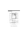
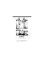
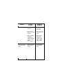
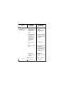
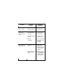
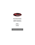
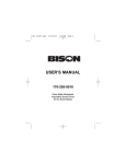
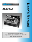
USER’S MANUAL
Models:
170-243-0003
170-243-0010
Pulse-Width Modulated, Adjustable Speed,
Cased Drives for DC Brush Motors
Copyright © 2006 by
Bison Gear & Engineering
All rights reserved. No part of this manual may be reproduced or transmitted in any
form without written permission from Bison Gear & Engineering. The information and
technical data in this manual are subject to change without notice. Bison Gear &
Engineering and its Divisions make no warranty of any kind with respect to this
material, including, but not limited to, the implied warranties of its merchantability
and fitness for a given purpose. Bison Gear & Engineering and its Divisions assume
no responsibility for any errors that may appear in this manual and make no
commitment to update or to keep current the information in this manual. MVD062402
Printed in the United States of America.
i
Safety Warnings
SHOCK
HAZARD
AVOID
HEAT
KEEP
DRY
AVOID
VIBRATION
•
denotes an important safety tip or warning.
This symbol
Please read these sections carefully prior to performing any of
the instructions contained in that section.
•
Have a qualified electrical maintenance technician install, adjust
and service this equipment. Follow the National Electrical Code
and all other applicable electrical and safety codes, including the
provisions of the Occupational Safety and Health Act (OSHA),
when installing equipment.
•
Reduce the chance of an electrical fire, shock, or explosion by
proper grounding, over-current protection, thermal protection,
and enclosure. Follow sound maintenance procedures.
It is possible for a drive to run at full speed as a result of
a component failure. Bison strongly recommends the
installation of a master switch in the main power input to stop
the drive in an emergency.
Circuit potentials are at 115 VAC above earth ground.
Avoid direct contact with the printed circuit board or with circuit
elements to prevent the risk of serious injury or fatality. Use a
non-metallic screwdriver for adjusting the calibration trimpots.
Use approved personal protective equipment and insulated
tools if working on this drive with power applied.
ii
Contents
Safety Warnings . . . . . . . . . . . . . . . . . . . . . . . . . . . . . . . . . . . . . . . . . . .i
Specifications . . . . . . . . . . . . . . . . . . . . . . . . . . . . . . . . . . . . . . . . . . . .1
Dimensions . . . . . . . . . . . . . . . . . . . . . . . . . . . . . . . . . . . . . . . . . . . . . . .5
Installation
Mounting
. . . . . . . . . . . . . . . . . . . . . . . . . . . . . . . . . . . . . . . . . . . . . .7
. . . . . . . . . . . . . . . . . . . . . . . . . . . . . . . . . . . . . . . . . . . . . . . . . . . .7
Connections . . . . . . . . . . . . . . . . . . . . . . . . . . . . . . . . . . . . . . . . . . . . . . . . . .9
Shielding guidelines . . . . . . . . . . . . . . . . . . . . . . . . . . . . . . . . . . . . . . .12
Field Output . . . . . . . . . . . . . . . . . . . . . . . . . . . . . . . . . . . . . . . . . . . . . . . . .13
Fusing . . . . . . . . . . . . . . . . . . . . . . . . . . . . . . . . . . . . . . . . . . . . . . . . . . . . . .14
Line Fusing Drives . . . . . . . . . . . . . . . . . . . . . . . . . . . . . . . . . . . . . . . . . . . .15
Voltage Follower . . . . . . . . . . . . . . . . . . . . . . . . . . . . . . . . . . . . . . . . . . . . . .16
Terminal Block . . . . . . . . . . . . . . . . . . . . . . . . . . . . . . . . . . . . . . . . . . . . . . .17
Operation . . . . . . . . . . . . . . . . . . . . . . . . . . . . . . . . . . . . . . . . . . . . . . .18
Before applying power:
. . . . . . . . . . . . . . . . . . . . . . . . . . . . . . . . . . . . . . . .18
Startup . . . . . . . . . . . . . . . . . . . . . . . . . . . . . . . . . . . . . . . . . . . . . . . . . . . . .19
Diagnostic LEDs . . . . . . . . . . . . . . . . . . . . . . . . . . . . . . . . . . . . . . . . . . . . . .19
Line starting and line stopping . . . . . . . . . . . . . . . . . . . . . . . . . . . . . . . . . . .21
Inhibit circuit . . . . . . . . . . . . . . . . . . . . . . . . . . . . . . . . . . . . . . . . . . . . . . . . .21
Decelerating to minimum speed
Dynamic braking
. . . . . . . . . . . . . . . . . . . . . . . . . . . . . . . . .23
. . . . . . . . . . . . . . . . . . . . . . . . . . . . . . . . . . . . . . . . . . . . .24
Calibration . . . . . . . . . . . . . . . . . . . . . . . . . . . . . . . . . . . . . . . . . . . . . .26
MINIMUM SPEED (MIN SPD) . . . . . . . . . . . . . . . . . . . . . . . . . . . . . . . . . . .27
MAXIMUM SPEED (MAX SPD) . . . . . . . . . . . . . . . . . . . . . . . . . . . . . . . . . .27
ACCELERATION (ACCEL)
. . . . . . . . . . . . . . . . . . . . . . . . . . . . . . . . . . . . .28
DECELERATION (DECEL)
. . . . . . . . . . . . . . . . . . . . . . . . . . . . . . . . . . . . .28
IR COMPENSATION (IR COMP) . . . . . . . . . . . . . . . . . . . . . . . . . . . . . . . . .29
iii
CURRENT LIMIT (CURR LIMIT) 170-243-0003 or
TORQUE LIMIT (TORQ LIMIT) 170-243-0010 . . . . . . . . . . . . . . . . . . . . . . .30
Calibration with low voltage DC motors . . . . . . . . . . . . . . . . . . . . . . . . . . . .32
Application Notes . . . . . . . . . . . . . . . . . . . . . . . . . . . . . . . . . . . . . . . .34
Leader-follower application
. . . . . . . . . . . . . . . . . . . . . . . . . . . . . . . . . . . . .34
Single speed potentiometer control of multiple drives . . . . . . . . . . . . . . . . .35
Troubleshooting . . . . . . . . . . . . . . . . . . . . . . . . . . . . . . . . . . . . . . . . . .36
Before troubleshooting . . . . . . . . . . . . . . . . . . . . . . . . . . . . . . . . . . . . . . . . .36
Certificate of Compliance
. . . . . . . . . . . . . . . . . . . . . . . . . . . . . . . . .40
AC Line Filters . . . . . . . . . . . . . . . . . . . . . . . . . . . . . . . . . . . . . . . . . . . . . . .40
Unconditional Warranty . . . . . . . . . . . . . . . . . . . . . .inside back cover
Tables
Table
Table
Table
Table
1.
2.
3.
4.
Field Output Connections . . . . . . . . . . . . . . . . . . . . . . . . . . . . . . . . . . . .13
Fuse Chart . . . . . . . . . . . . . . . . . . . . . . . . . . . . . . . . . . . . . . . . . . . . . . .15
Recommended Dynamic Brake Resistor Sizes . . . . . . . . . . . . . . . . . . .25
AC Line Filters . . . . . . . . . . . . . . . . . . . . . . . . . . . . . . . . . . . . . . . . . . . .41
iv
Illustrations
Figure
Figure
Figure
Figure
Figure
Figure
Figure
Figure
Figure
Figure
Figure
Figure
Figure
Figure
Figure
1. 170-243-0003 Dimensions . . . . . . . . . . . . . . . . . . . . . . . . . . . . . . . . . . . .5
2. 170-243-0010 Dimensions . . . . . . . . . . . . . . . . . . . . . . . . . . . . . . . . . . . .6
3. 170-243-0003 Connections . . . . . . . . . . . . . . . . . . . . . . . . . . . . . . . . . . .9
4. 170-243-0010 Connections . . . . . . . . . . . . . . . . . . . . . . . . . . . . . . . . . .10
5. Prewired Connections for Models 170-243-0003 and 170-243-0010 . .11
6. Voltage Follower Connections . . . . . . . . . . . . . . . . . . . . . . . . . . . . . . . .16
7. Cage-Clamp Terminal . . . . . . . . . . . . . . . . . . . . . . . . . . . . . . . . . . . . . .17
8. Voltage Switch Location . . . . . . . . . . . . . . . . . . . . . . . . . . . . . . . . . . . . .18
9. Diagnostic LED Location . . . . . . . . . . . . . . . . . . . . . . . . . . . . . . . . . . . .20
10. Inhibit Plug with Run/Coast to Zero Speed Switch . . . . . . . . . . . . . . .22
11. Run/Decelerate to Minimum Speed Switch . . . . . . . . . . . . . . . . . . . . .23
12. Dynamic Brake Connection . . . . . . . . . . . . . . . . . . . . . . . . . . . . . . . . .24
13. 170-243-0003 CURR LIMIT and IR COMP Settings . . . . . . . . . . . . . .31
14. 170-243-0010 TORQ. LIMIT and IR COMP Settings . . . . . . . . . . . . .31
15. 170-243-0003 MAX SPEED Settings for
Low Voltage DC Motors . . . . . . . . . . . . . . . . . . . . . . . . . . . . . . . . . . . .32
Figure 16. 170-243-0010 MAX SPD Settings for
Low Voltage DC Motors . . . . . . . . . . . . . . . . . . . . . . . . . . . . . . . . . . . .33
Figure 17. Leader-Follower Application . . . . . . . . . . . . . . . . . . . . . . . . . . . . . . . . .34
Figure 18. Single Speed Potentiometer Control of Multiple Drives . . . . . . . . . . . .35
1
Specifications
Model Number
170-243-0003
Type:
Cased
NEMA Rating
NEMA 4X
AC Line Voltage 115 VAC/230 VAC, ±10%, 50/60 Hz, single phase
Line Fuse Rating
8A
Horsepower Range @ 130 VDC Output
1/20–1/3 HP
Horsepower Range @ 240 VDC Output
1/8–1/2 HP
Maximum Armature Voltage Range @ 115 VAC Input 50–130 VDC
Maximum Armature Voltage Range @ 230 VAC Input 50–240 VDC
Minimum Speed Adjustment Range @ 115 VAC Input
0–65 VDC
Minimum Speed Adjustment Range @ 230 VAC Input
0–65 VDC
Maximum Armature Current
3 ADC
Field Voltage @ 115 VAC Input
50 VDC/100 VDC
Field Voltage @ 230 VAC Input
100 VDC/200 VDC
Maximum Field Current
1 ADC
Form Factor
1.05
Acceleration Time Range (no load)
for 0–130 VDC Armature Voltage Range
1–10 seconds
for 0–240 VDC Armature Voltage Range
1–19 seconds
Deceleration Time Range (no load)
for 0–130 VDC Armature Voltage Range
3–9 seconds
for 0–240 VDC Armature Voltage Range
4–19 seconds
Analog Input Voltage Range (signal must be isolated; S1 to S2)
for 0–130 VDC Armature Voltage
0–2.7 VDC
for 0–240 VDC Armature Voltage
0–5.0 VDC
2
Speed Adjustment Potentiometer
Approximate Input Impedance (from S1 to S2)
Speed Regulation (at base speed)
Weight
Ambient Operating Temperature Range
Vibration
10K ohms
100K ohms
1%
4.4 lb
10ºC–40ºC
0.5g max (0 – 50 Hz)
0.1g max (above 50 Hz)
3
Model Number
Type
NEMA Rating
AC Line Voltage
170-243-0010
Cased
NEMA 4X
115 VAC/230 VAC, ±10%, 50/60 Hz, single phase
Line Fuse Rating
15 A
Horsepower Range @ 130 VDC Output
1/4–1 HP
Horsepower Range @ 240 VDC Output
1/4–2 HP
Maximum Armature Voltage Range @ 115 VAC Input 50–130 VDC
Maximum Armature Voltage Range @ 230 VAC Input 50–240 VDC
Minimum Speed Adjustment Range @ 115 VAC Input 0–120 VDC
Minimum Speed Adjustment Range @ 230 VAC Input 0–120 VDC
Maximum Armature Current
10 ADC
Field Voltage @ 115 VAC Input
50 VDC/100 VDC
Field Voltage @ 230 VAC Input
100 VDC/200 VDC
Maximum Field Current
1 ADC
Form Factor
1.05
Acceleration Time Range (no load)
for 0–130 VDC Armature Voltage Range
1–10 seconds
for 0–240 VDC Armature Voltage Range
1–15 seconds
Deceleration Time Range (no load)
for 0–130 VDC Armature Voltage Range
1–10 seconds
for 0–240 VDC Armature Voltage Range
1–19 seconds
Analog Input Voltage Range (signal must be isolated; S1 to S2)
for 0–130 VDC Armature Voltage
0–2.7 VDC
for 0–240 VDC Armature Voltage
0–5.0 VDC
Speed Adjustment Potentiometer
10K ohms
4
Approximate Input Impedance (from S1 to S2)
50K ohms
Speed Regulation (at base speed)
1%
Weight
7.4 lb
Ambient Operating Temperature Range
10ºC–40ºC
Vibration
0.5g max (0 – 50 Hz)
0.1g max (above 50 Hz)
5
Dimensions
6.90 [175]
0.91 [23]
40
30
20
10
0
50
60
70
80
90
100
7.78 [197]
8.20 [207]
6.00 [152]
FOUR MOUNTING SLOTS 0.19 [5] WIDE
4.43 [112]
3.29 [83]
1.92 [49]
0.13 [3]
2.50 [63]
TWO 0.88 [22] KNOCKOUTS
ALL DIMENSIONS IN INCHES [MILLIMETERS]
Figure 1. 170-243-0003 Dimensions
6
6.90 [175]
6.30 [159]
40
30
20
10
0
1.37 [35]
50
60
70
80
90
100
10.22 [259]
9.75 [247]
7.00 [177]
FOUR MOUNTING SLOTS 0.19 [5] WIDE
5.79 [146]
4.69 [119]
1.45 [37]
2.31 [58]
1.50 [38]
1.50 [38]
0.12 [3]
THREE 0.88 [22] KNOCKOUTS
ALL DIMENSIONS IN INCHES [ MILLIMETERS]
Figure 2. 170-243-0010 Dimensions
7
Installation
Mounting
Nema 4X cased drives come with 0.88 inch (22 mm) conduit
knockout holes at the bottom of the case. The units may be
vertically wall mounted using the four 0.19 inch (5 mm) slotted
holes on the attached heat sink. For motor loads less than 5 ADC,
the drive may be bench mounted horizontally, or operated without
mounting.
1. Install the mounting screws through the drive’s four mounting
slots.
2. For access to the terminal strip, turn the slotted screw on the
front cover counterclockwise until it is free from the case. The
right side of the cover is hinged to the case. Pull the slotted
screw to open the case.
3. Carefully remove the 0.88 inch (22 mm) conduit knockouts by
tapping them into the case and twisting them off with pliers.
4. Install conduit hardware through the knockout holes. Connect
external wiring to the terminal block.
8
5. Grasp the slotted screw and tilt the front cover back into place.
Avoid pinching any wires between the front cover and the case.
6. Turn the slotted screw clockwise until tight to secure the front
cover.
7. Set the POWER switch to the OFF position before applying the
AC line voltage.
9
Connections
Bison drives supply motor voltage to terminals A1 and A2 (A1 is
positive with respect to A2). It is assumed throughout this manual
that the driven motor will rotate clockwise (CW) while looking at the
output shaft protruding from the front of the motor. If the opposite is
desired, simply reverse the wiring of A1 and A2 with each other.
TB501
L1
115
230
F1
F2
A2
A1
115
Motor
AC Line Voltage
115 or 230 VAC
230
+
Field Output Shunt wound motors only.
See Field Output section for
connections.
Figure 3. 170-243-0003 Connections
Armature
Output
10
POWER ON CURR LIMIT
PS4
PS2
PS1
PS3
IL501
IL502
SO502
S0503
POWER
CURR
SO504
+15
C505
SO501
INHIBIT
MIN SPD
DECEL
S1
ACCEL
S2
S3
TB501
L1
230
115
F+
FAST-ACTING
FUSE ONLY FU502
FAST-ACTING
FUSE ONLY FU502
FAST-ACTING
FUSE ONLY FU501
MAX SPD TORQ. LIMIT IR COMP
JOG
SPD SPD JOG
IN
SPD
230
115
JOG
SPD and SPD IN are
prewired for speed adjust
poteniometer control.
A1
F-
To control speed with JOG
trimmer potentiometer,
connect SPD IN to JOG.
A2
Motor will not turn if there is
no connection to SPD IN.
TB501
L1
SPD
IN
A2
F+
A1
F-
A2
230
Motor
Armature
Output
AC Line Voltage
115 or 230 VAC
115
Field Output Shunt wound motors only.
See Field Output section for
connections.
Figure 4. 170-243-0010 Connections
11
Power
Switch
PS1
black
black/white
PS2
Power
Light
PS3
S1
S2
S3
white
violet
brown
white/black
CW
10K ohm
Speed Adjust
Potentiometer
grey
Figure 5. Prewired Connections for Models
170-243-0003 and 170-243-0010
PS4
12
Shielding guidelines
Warning
Under no circumstances should power and logic leads be
bundled together. Induced voltage can cause unpredictable
behavior in any electronic device, including motor controls.
As a general rule, Bison recommends shielding of all conductors.
If it is not practical to shield power conductors, Bison recommends
shielding all logic-level leads. If shielding is not practical, the user
should twist all logic leads with themselves to minimize induced
noise.
It may be necessary to earth ground the shielded cable. If noise is
produced by devices other than the drive, ground the shield at the
drive end. If noise is generated by a device on the drive, ground
the shield at the end away from the drive. Do not ground both ends
of the shield.
If the drive continues to pick up noise after grounding the shield, it
may be necessary to add AC line filtering devices, or to mount the
drive in a less noisy environment.
Logic wires from other input devices, such as motion controllers
and PLL velocity controllers, must be separated from power lines in
the same manner as the logic I/O on this drive.
13
Field Output
The field output is for shunt wound motors only. Do not make any
connections to the field output when using a permanent magnet
motor. Table 1 shows where to connect the field leads of a shunt
wound motor.
Table 1. Field Output Connections
Line Voltage
(VAC)
Approximate Field
Voltage (VDC)
170-243-0003
Connections
170-243-0010
Connections
115
50
F1 and L1
F+ and L1
115
100
F1 and F2
F+ and F-
230
100
F1 and L1
F+ and L1
230
200
F1 and F2
F+ and F-
Use 16 AWG wire to connect the field output to a shunt wound
motor.
14
Fusing
170-243-0003: This drive comes with two 8A fuses installed
(FU501 and FU502). FU501 connects with the L1 terminal (the hot
leg of the AC line voltage). FU502 connects with the 230 terminal.
If the current rating of the motor is less than the maximum current
rating of the drive, replace the fuse with a lower rated one. Rate
fuses at 150% times the maximum armature current.
170-243-0010: This drives comes with two 15A fuses installed
(FU501 - FU502). FU501 connects with the L1 terminal (the hot
leg of the AC line voltage). FU502 connects with the 230 terminal.
If the current rating of the motor is less than the maximum current
rating of the drive, replace the fuse with a lower rated one. Rate
fuses at 150% times the maximum armature current.
15
Line Fusing
Bison drives require an external fuse for protection. Use fast acting
fuses rated for 250 VAC or higher, and approximately 150% of the
maximum armature current. Fuse both L1 and L2 when the line
voltage is 230 VAC. Fuse blocks are included on cased drives
only. The fuse chart below lists the recommended line fuse sizes.
Table 2. Fuse Chart
90 VDC Motor
Horsepower
180 VDC
Horsepower
Max. DC Armature
Current (amps)
AC Line Fuse
Size (amps)
1/20
1/10
0.5
1
1/15
1/8
0.8
1.5
1/8
1/4
1.5
3
1/6
1/3
1.7
3
1/4
1/2
2.6
5
1/3
3/4
3.5
8
1/2
1
5.0
10
3/4
1 1/2
7.6
15
1
2
10
15
16
Voltage Follower
Instead of using a speed adjust potentiometer, the drive may be
wired to follow a voltage signal that is isolated from earth ground
(Figure 6). Connect the signal input (+) to S2. Connect the signal
common (-) to S1. Make no connection to S3. A potentiometer
can be used to scale the analog input voltage. To achieve greater
linearity and control, use an interface device such as Bison model
170-993-0200 to scale the analog input voltage.
Refer to the Specifications section on page 1 for the analog input
voltage range of the drive you are using.
DRIVE
SIGNAL INPUT (+)
S2
SIGNAL COMMON (-)
S1
Figure 6. Voltage Follower Connections
17
Terminal Block
All these drives use a cage-clamp spring terminal block. To open
the clamp spring, use a small screwdriver to press down on the
lever above the terminal block. To insert a wire into a terminal, use
the following procedure:
1 Press down on the lever arm
using a small screwdriver.
2 Insert wire into the wire clamp.
3 Release the lever arm to clamp
the wire.
Figure 7. Cage-Clamp Terminal
18
Operation
Before applying power:
1. Verify that no conductive material is present on the printed
circuit board.
2. Set both voltage selection switches (SW501 and SW502) to
either 115 or 230 VAC to match the AC line voltage being used.
(see Figure 8 below).
Warning
Change voltage selection switch settings only when the
drive is disconnected from the AC line voltage. Make sure
that both switches are set to the correct position. If the
switches are improperly set to a lower voltage position, the
motor will not run at full voltage. If the switches are
improperly set to a higher voltage position, the motor will
over speed, which may cause motor damage.
BR+
TH501
Q501
C504
BR-
AC2
AC1
T501
1
B2
C505
115
230
SW501
VOLTAGE SELECT
SWITCHES
(SW501 and SW502)
D501
R503
SW502
230
115
C501
IC503
Figure 8. Voltage Switch Location
R501
19
Startup
1.
2.
3.
4.
Set the speed adjust potentiometer to zero (full CCW).
Apply AC line voltage.
Set the POWER switch to the ON position.
Slowly advance the speed adjust potentiometer clockwise (CW).
The motor slowly accelerates as the potentiometer is turned
CW. Continue until the desired speed is reached.
5. Set the POWER switch to the OFF position to coast the motor
to a stop.
If the motor or drive does not perform as described, disconnect the
AC line voltage immediately. Refer to the Troubleshooting section
on page 36 for further assistance.
Diagnostic LEDs
This series of drives are equipped with diagnostic LEDs. The
green POWER ON LED turns on when power is applied to the
drive and turns off when power is removed. The red CURR LIMIT
LED turns on when the drive reaches current limit and turns off
when the drive is not in current limit (normal operation). See
Figure 9 on page 20 for Diagnostic LED locations.
20
POWER ON CURR LIMIT
PS2
IL501
IL502
SO502
SO503
PS4
PS1
PS3
POWER
SO504
SO501
+15
INHIBIT
CURR
C505
IR COMP
MAX SPD TORQ. LIMIT
170-243-0010 LEDs
170-243-0003 LEDs
PS1
PS3
S1
S3
S2
SO502
-15V+
MAX SPD CURR LIMIT
IR COMP
SO501
MIN SPD
ACCEL
DECEL
INHIBIT
POWER CURR
ON
LIMIT
IL501
TB501
L1
115
230
F1
F2
A2
A1
Figure 9. Diagnostic LED Location
IL502
21
Line starting and line stopping
Line starting and line stopping (applying and removing AC line
voltage) is recommended for infrequent starting and stopping of a
drive only. When AC line voltage is applied to the drive, the motor
accelerates to the speed set by the speed adjust potentiometer.
When AC line voltage is removed, the motor coasts to a stop.
Inhibit circuit
Warning
The inhibit circuit is used for frequent starts and stops. It
must never be used as an emergency stop. The inhibit
circuit may not stop a drive that is malfunctioning.
Removing AC line power (both L1 and L2) is the only
acceptable method for emergency stopping.
Maintaining a connection between the inhibit pins causes the motor
to coast to zero speed. Removing the connection between the
inhibit pins allows the motor to accelerate the speed set by the
speed adjust potentiometer. See Figure 10 on Page 22.
22
Bison Gear & Engineering offers an accessory plug harness for
connecting to the inhibit pins: part number 170-998-0100 [inhibit
plug with 36 in. (91 cm) leads]. Twist these leads and separate
them from other power-carrying wires or sources of electrical noise.
Use shielded cable if the inhibit leads are longer than 18 in. (46
cm).
RUN
INHIBIT
COAST TO
ZERO SPEED
Figure 10. Inhibit Plug with Run/Coast to Zero Speed Switch
23
Decelerating to minimum speed
The circuit shown in Figure 11 may be used to decelerate a motor
to a minimum speed. Closing the switch between S1 and S2
decelerates the motor from set speed to a minimum speed
determined by the MIN SPD trimpot setting. If the MIN SPD trimpot
is set full CCW, the motor decelerates to zero speed when the
switch between S1 and S2 is closed. The DECEL trimpot setting
determines the rate at which the drive decelerates. By opening the
switch, the motor accelerates to set speed at a rate determined by
the ACCEL trimpot setting.
CW
S3
10K OHM
SPEED ADJUST
POTENTIOMETER
S2
S1
RUN
DECEL TO
MIN SPEED
Figure 11. Run/Decelerate to Minimum Speed Switch
24
Dynamic braking
Dynamic braking may be used to rapidly stop a motor (Figure 12).
For the RUN/BRAKE switch, use a double pole, double throw
switch rated for at least the maximum DC armature voltage and
maximum braking current.
A1
A2
RUN
MOTOR
DYNAMIC BRAKE
RESISTOR
BRAKE
INHIBIT
Figure 12. Dynamic Brake Connection
25
Warning
Wait for the motor to come to a complete STOP before
switching back to the RUN position. This will prevent high
armature currents from damaging the motor or drive.
Size the dynamic brake resistor according to the motor current
rating (see Table 3). The dynamic brake resistance listed in the
table is the smallest recommended resistance allowed to prevent
possible demagnetization of the motor. The motor stops less rapidly
with higher brake resistor values.
Table 3. Recommended Dynamic Brake Resistor Sizes
Minimum
Motor Armature
Current Rating
Less than 2 ADC
2–3 ADC
3–5 ADC
5–10 ADC
10–17 ADC
Minimum
Dynamic Brake
Resistor Value
1 ohm
5 ohm
10 ohm
20 ohm
40 ohm
Dynamic Brake
Resistor Wattage
1W
5W
10W
20W
50W
For motors rated 1/17 horsepower and lower, a brake resistor is not
necessary since the armature resistance is high enough to stop the
motor without demagnetization. Replace the dynamic brake with 12
gauge wire.
26
Calibration
Warning
Dangerous voltages exist on the drive when it is powered,
and up to 30 seconds after power is removed and the motor
stops. When possible, disconnect the voltage input from the
drive before adjusting the trimpots. If the trimpots must be
adjusted with power applied, use insulated tools and the
appropriate personal protection equipment. BE ALERT.
High voltages can cause serious or fatal injury.
Each drive is factory calibrated to its maximum current rating.
Readjust the calibration trimpot settings to accommodate lower
current rated motors.
All adjustments increase with CW rotation, and decrease with CCW
rotation. Use a non-metallic screwdriver for calibration. Each
trimpot is identified on the printed circuit board.
27
MINIMUM SPEED (MIN SPD)
The MIN SPD setting determines the motor speed when the speed
adjust potentiometer is turned full CCW. It is factory set to zero
speed.
To calibrate, turn the speed adjust potentiometer full CCW. To set
the minimum speed to zero, rotate the MIN SPD trimpot CCW until
the motor has stopped. To set a minimum speed higher than zero,
rotate the MIN SPD trimpot CW until the motor is running at the
desired minimum speed.
MAXIMUM SPEED (MAX SPD)
The MAX SPD setting determines the motor speed when the speed
adjust potentiometer is turned full CW. It is factory set for maximum
rated speed.
To calibrate, set the MAX SPD trimpot full CCW. Turn the speed
adjust potentiometer full CW. Adjust the MAX SPD trimpot until the
desired maximum motor speed is reached.
Note: Check the MIN SPD and MAX SPD adjustments after
recalibrating to verify that the motor runs at the desired minimum
and maximum speed.
28
ACCELERATION (ACCEL)
The ACCEL setting determines the time the motor takes to ramp to
a higher speed. See Specifications on page 1 for approximate
acceleration times. The ACCEL setting is factory set to its
minimum value (full CCW).
Turn the ACCEL trimpot CW to increase the acceleration time, and
CCW to decrease the acceleration time.
DECELERATION (DECEL)
The DECEL setting determines the time the motor takes to ramp to
a lower speed. See Specifications on page 1 for approximate
deceleration times. The DECEL setting is factory set to its
minimum value (full CCW).
Turn the DECEL trimpot CW to increase the deceleration time, and
CCW to decrease the deceleration time.
29
IR COMPENSATION (IR COMP)
The IR COMP setting determines the degree to which motor speed
is held constant as the motor load changes. It is factory set for
optimum motor regulation.
Recalibrate the IR COMP setting when using a lower horsepower
motor. Refer to the recommended IR COMP settings in Figure 13
or 14 on Page 31, or recalibrate using the following procedure:
To calibrate IR COMP (exact calibration):
1. Set the speed adjust potentiometer until the motor runs at
midspeed
(for example, 900 RPM for an 1800 RPM motor).
2. Load the motor armature to its full load armature current rating.
The motor should slow down.
3. While keeping the load on the motor, rotate the IR COMP
trimpot until the motor runs at the speed measured in step 1.
Approximate calibration: If the motor does not maintain set speed
as the load changes, gradually rotate the IR COMP trimpot CW. If
the motor oscillates (overcompensation), the IR COMP trimpot may
be set too high (CW). Turn the IR COMP trimpot CCW to stabilize
the motor speed.
30
CURRENT LIMIT (CURR LIMIT) 170-243-0003
or TORQUE LIMIT (TORQ LIMIT) 170-243-0010
Warning
Although TORQUE LIMIT is set to 120% of motor nameplate
current rating, continuous operation beyond that rating may
damage the motor. If you intend to operate beyond the
rating, contact your Bison representative for assistance.
The CURR LIMIT or TORQ LIMIT setting determines the maximum
armature current output of the drive. It is factory set at 120% of
rated motor current. Recalibrate the CURR LIMIT or TORQ LIMIT
setting when using a lower horsepower motor. Refer to the
recommended trimpot settings on page 31, or recalibrate using the
following procedure:
1. With the power disconnected from the control, connect a DC
ammeter (0 - 15 A minimum scale) in series with the armature.
2. Set the CURR LIMIT or TORQ LIMIT trimpot to minimum (full
CCW).
3. Set the speed adjust potentiometer to maximum (full CW).
4. Lock the motor armature. Be sure that the motor is firmly
mounted.
5. Connect power to the drive. The motor should remain stopped.
6. Adjust the CURR LIMIT or TORQ LIMIT trimpot CW slowly until
armature current is 120% of motor rated current.
7. Set the speed adjust potentiometer to minimum.
8. Remove power.
9. Remove the stall from the motor.
31
CURR LIMIT
CURR LIMIT
CURR LIMIT
IR COMP
IR COMP
IR COMP
1/20 HP
90 VDC
1750 RPM
0.5 Amps
1/8 HP
90 VDC
1750 RPM
1.3 Amps
1/4 HP
90 VDC
1750 RPM
2.5 Amps
CURR LIMIT
CURR LIMIT
CURR LIMIT
IR COMP
IR COMP
IR COMP
1/8 HP
180 VDC
1750 RPM
0.67 Amps
1/4 HP
180 VDC
1750 RPM
1.4 Amps
1/3 HP
180 VDC
1750 RPM
1.75 Amps
Figure 13. 170-243-0003 CURR LIMIT and IR COMP Settings
TORQ LIMIT IR COMP
TORQ LIMIT IR COMP
TORQ LIMIT IR COMP
1/4 HP
90 VDC
1750 RPM
2.5 Amps
1/2 HP
90 VDC
1750 RPM
5 Amps
1/4 HP
90 VDC
1750 RPM
10 Amps
TORQ LIMIT IR COMP
TORQ LIMIT IR COMP
TORQ LIMIT IR COMP
1/2 HP
180 VDC
1750 RPM
2.5 Amps
1 HP
180 VDC
1750 RPM
5 Amps
2 HP
180 VDC
1750 RPM
9 Amps
Figure 14. 170-243-0010 TORQ. LIMIT and IR COMP Settings
32
Calibration with low voltage DC motors
Using this series drive with a low voltage DC motor requires using
a lower resistance speed adjust potentiometer, and recalibrating
the MAX SPEED trimpot settings. See Figure 15 below and Figure
16 on page 33 for MAX SPEED trimpot settings.
NOTE: MAX SPEED trimpot settings are approximate. Verify
maximum armature voltage with a voltmeter.
MAX SPEED TRIMPOT SETTING
MOTOR ARMATURE
VOLTAGE (VDC)
USING 2.5K OHM
SPEED ADJUST
POTENTIOMETER
USING 1.5K OHM
SPEED ADJUST
POTENTIOMETER
12
24
36
48
Figure 15. 170-243-0003 MAX SPEED Settings for
Low Voltage DC Motors
33
MAX SPEED TRIMPOT SETTING
MOTOR ARMATURE
VOLTAGE (VDC)
USING 2.5K OHM
SPEED ADJUST
POTENTIOMETER
USING 1.5K OHM
SPEED ADJUST
POTENTIOMETER
12
NOT
APPLICABLE
NOT
APPLICABLE
24
NOT
APPLICABLE
NOT
APPLICABLE
36
48
Figure 16. 170-243-0010 MAX SPD Settings for
Low Voltage DC Motors
34
Application Notes
Leader-follower application
In this application, use a 170-993-0200 to monitor the speed of the
leader motor (Figure 17). The 170-993-0200 isolates the leader
motor from the follower drive, and outputs a voltage proportional to
the leader motor armature voltage. The follower drive uses this
voltage reference to set the speed of the follower motor. An
optional ratio potentiometer may be used to scale the 170-9930200 output voltage.
MOTOR
A2
(+) 2
9 (+)
A1
Leader
Drive
S2
170-993-0200 (-) 1
8
7 (-)
TB501
TB502
S1
10K Ohm
(optional)
Figure 17. Leader-Follower Application
Follower
Drive
35
Single speed potentiometer control of
multiple drives
Multiple drives can be controlled with a single speed adjust
potentiometer using a 170-993-0200 at the input of each drive to
provide isolation (Figure 18). Optional ratio potentiometers can be
used to scale the 170-993-0200 output voltage, allowing
independent control of each drive.
6
10K Ohms
8
2
7
1
2
S1
Motor
A
A2
ratio pot B
(optional)
10K Ohms
A1
S2
170-993-0200
7
Drive
A
TB502
6
TB501
A1
S2
170-993-0200
TB501
8
ratio pot A
(optional)
10K Ohms
1
S1
Motor
B
Drive
B
A2
TB502
Figure 18. Single Speed Potentiometer Control of Multiple Drives
36
Troubleshooting
Warning
Dangerous voltages exist on the drive when it is powered,
and up to 30 seconds after power is removed and the motor
stops. When possible, disconnect the AC line voltage from
the drive while troubleshooting. Be alert. High voltages can
cause serious or fatal injury.
Before troubleshooting
Perform the following steps before starting any procedure in this
section:
1. Disconnect AC line voltage from the drive.
2. Check the drive closely for damaged components.
3. Check that no conductive or other foreign material is lodged on
the printed circuit board.
4. Verify that every connection is correct and in good condition.
5. Verify that there are no short circuits or grounded connections.
6. Check that the voltage selection switch settings match the AC
line and output voltages.
37
Problem
Line fuse blows
Motor runs too fast
at maximum speed
setting
Possible
Causes
Suggested
Solutions
1. Line fuses are the
wrong size.
1. Check that line
fuses are the
correct size.
2. Motor cable or
armature is shorted
to ground.
2. Check motor cable
and armature for
shorts.
3. Nuisance tripping
caused by a
combination of
ambient conditions
and high-current
spikes
(i.e. reversing).
3. Add a blower to
cool the drive
components;
increase CURR
LIMIT or TORQ
LIMIT settings.
1. MIN SPD and MAX
SPD settings are
too high.
1. Recalibrate MIN
SPD and MAX
SPD.
38
Problem
Possible
Causes
Suggested
Solutions
Line fuse is not
blown, but the
motor does not run
1. Speed adjust
potentiometer, or
voltage input signal
is set to zero
speed.
1. Increase the speed
adjust
potentiometer, or
voltage setting.
2. Speed adjust pot,
or voltage input
signal, is not
connected to drive
input properly;
connections are
open.
2. Check connections
to input. Verify that
connections are
not open.
3. S2 is shorted to
S0.
3. Remove short.
4. Drive is in current
limit.
4. Verify that motor is
not jammed.
Increase the TORQ
or CURR LIMIT
setting. It may be
set too low.
5. Drive is not
receiving AC line
voltage.
5. Apply AC line
voltage to L1 and
L2.
6. Motor is not
connected.
6. Connect motor to
A1 and A2.
39
Problem
Possible
Causes
Suggested
Solutions
Motor runs too
slow or too fast
1. MIN SPD and MAX
SPD not calibrated.
1. Calibrate MIN SPD
and MAX SPD.
Motor will not
reach the desired
speed
1. MAX SPD setting
is too low.
1. Increase MAX
SPD setting.
2. IR COMP setting is
too low.
2. Increase the IR
COMP setting.
3. Motor is
overloaded.
3. Check motor load.
Resize the motor
and drive if
necessary.
1. IR COMP is set too
high.
1. Adjust the IR
COMP setting
slightly CCW until
the motor speed
stabilizes.
2. Motor “bouncing” in
and out of torque
limit.
2. Make sure motor
is not undersized
for load; adjust the
CURR or TORQ
LIMIT trimpot.
Motor pulsates or
surges under load
40
Certificate of Compliance
Bison Gear & Engineering hereby certifies that this series of drives
(models 170-243-0003 and 170-243-0010) have been approved to
bear the “CE” mark provided the conditions of approval have been
met by the end user.
This series has been tested to the following test specifications:
EN55014:1993 (emmisions), and
EN50082-1:1992 (immunity)
Compliance allows Bison’s series to bear the CE mark.
The end user, as described herein, falls into one of two categories:
1. The Consumer will deploy a stand-alone unit as an
integral, yet external, portion of the machine being
operated.
2. The Original Equipment Manufacturer (OEM) will
implement the product as a component of the machine
being manufactured.
AC Line Filters
In addition to EMI/RFI safeguards inherent in this series’ design,
external filtering is required.
Bison requires the AC line filters listed in Table 4. Use model 170893-0004 with drives rated for 3A AC or below, and model 170893-0015 for drives rated 15A AC or below.
41
Table 4. AC Line Filters
Bison Model Number
Rated Current
Inductance
Capacitance
Line to Line
Line to Ground
Discharge Resistor
170-893-0004
4A
17.5 mH
170-893-0015
15A
10.0mH
0.82 mF
0.0056 mF
330 KW
0.82 mF
0.0056 mF
330 KW
Wire the AC line filter within 0.25 meters of the drive. The ground
connection from the filter must be wired to solid earth ground (resistance
less than 500 ohms); not machine ground. This is very important!
If the end-user is using a CE-approved motor, the correct filter from
Table 4 is all that is necessary to meet the EMC directives listed herein.
42
NOTES
43
NOTES
44
NOTES
Bison Warranty Policy
The Company warrants to the Buyer the products sold hereunder to be
free of defects in material and workmanship under normal use and service
for a period of one (1) year from the date of shipment. The obligation of
the Company under this warranty is limited to repair or replacing at its
option, any part or parts, which upon examination shall disclose to the
reasonable satisfaction of the Company to have been defective in material
or workmanship. Buyer must return the products to the Company’s
factory, shipping charges prepaid, and with complete information as to
alleged defects and the installation, operation and service of the products.
Except as otherwise expressly stated herein the Company makes no
representation of warranty of any kind, express or implied, as to
merchantability, fitness for a particular purpose, or any other matter with
respect to the products sold hereunder.
Bison Gear & Engineering Corp.
3850 Ohio Ave. -- St. Charles, IL 60174
Phone: 1-800-AT-BISON
www.bisongear.com
Document Number: 250-0418; Revision 0 -- May 2006