1
Pump and valve controller
Firma TMK sp.j.
62-300 Września
Szosa Witkowska 105
tel./fax +48 61 437 97 60
www.tmk.com.pl
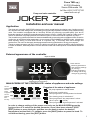
JOKER Z3P
Installation and user manual
Application
The electronic controller JOKER Z3P is designed to control central heating circulation pump, feeding pump of
the domestic hot water storage tank, floor heating pump (optionally tap water circulation pump) and the mixing
valve. The controller is equipped with an "anti-stop" function (to prevent the so-called pump "jam" due to
limescale deposits on bearings) and antibacterial protection function. JOKER Z3P features a wide range of
switch-on and switch-off pump hysteresis, as well as an option of manual override for operation of pumps.
The controller may prioritize domestic hot water and additionally prevent the tank and radiators from excessive
cooling due to insufficient boiler temperature. It can operate in the SUMMER or WINTER mode. It distributes
boiler capacity among CH and DHW circuits in a dynamic way, in conformity with user's settings and
preferences. The user can also apply timed programmes ensuring optimisation of energy consumption.
Thanks to advanced pump and valve control, the boiler can operate in optimal conditions which significantly
increase its lifetime, while temperature of both domestic water and heated spaces is maintained at desired
levels.
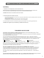
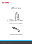
External appearance of the controller
MAIN SCREEN
CH
DHW
:30 Tue
FHP
WINTER
16
Knob used for:
- switching parameters
and changing settings
(by turning)
- selecting parameters
for editing and saving
changes (by pressing)
Multifunction touch buttons
MAIN SCREEN OF THE CONTROLLER - status of appliances and main settings
current
temperature
current
status
of appliances
current
settings
time
and day
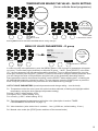
Examples of the status of appliances
CH
DHW
TUV
FHP
UK
:30 Tue
Parameters menu
16
/SUM
WINT
PK
CH pump operates in manual mode
DHW pomp is switched on
Timed programme 'cold temperature' activated
Floor heating pump is switched off
Timed programme "day temperature" activat
Valve is open ( - closed)
Timed programme "night temperature" activated
In order to change settings of the pumps and valve on the MAIN SCREEN press the
knob and turn it to select the desired parameter. Once it has been selected, press
[EDIT] button or press the knob, and then turn the knob to select the desired
temperature (arrows flash). To validate, press the [SAVE] button or press the knob. To
exit without saving, press the [EXIT] button.
1
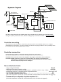
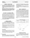
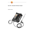
System layout
floor heating pump
TMV valve
Hot waterboiler
sensorcirculation pump
mixing valve
DHW tank sensor
boiler sensor
CH pump
sensor behind the valve
boiler
circulation sensor
DHW tank
DHW tank feeding pump
radiator
- CHECK VALVE
The above layout shows the floor heating pump being controlled "as CH" with the use of the thermostatic
mixing valve (TMV). Without this valve, the floor heating pump is controlled "as DHW" - (not recommended).
Controller mounting
The controller can be mounted on a wall mount (included in the kit as a standard option) or on a support
(available as an extra option). The mount is fixed to a wall with rawl plugs (included in the kit), following which
the controller can be easily snapped onto the mount.
Controller connection
Connect the supply cable to a 230V, 50Hz power outlet with an earth contact.
The ambient temperature in the controller mounting location may not exceed 40°C.
CAUTION: The connection cable of the regulator may only be replaced by the manufacturer.
CAUTION: JOKER controller is only able to operate when the system is filled with water
If the system is empty, the controller must be disconnected from the power supply.
Otherwise the pump may become damaged.
General technical data:
- Supply voltage 230V/50Hz
Default
- Maximum pump output 3x100VA, 1x20VA
settings
- "Anti-stop" function (pump protection against "jam") - activated for 30 sec. every 14 days
- Antibacterial protection of tank water against Legionella bacteria _ _ _ _ _ _ _ _ _ _ _ _ _ SWITCHED OFF
- Low CH boiler temperature alert 0-50°C _ _ _ _ _ _ _ _ _ _ _ _ _ _ _ _ _ _ _ _ _ _ _ _ _ _ _ _ _ _8°C
- High CH boiler temperature alert 60-120°C _ _ _ _ _ _ _ _ _ _ _ _ _ _ _ _ _ _ _ _ _ _ _ _ _ _ _ _92°C
(Once the temperature exceeds the set alert threshold, both the audible and visual alerts are triggered)
- Permanent alert (non-configurable) of low boiler temperature 8°C
- Permanent alert (non-configurable) of high boiler temperature 92°C
(Once the temperature exceeds the set alert threshold, only a visual alert is triggered)
2
CH PUMP CONTROL
Installation
1. Installation of the boiler sensor
ź Attach the sensor to an uninsulated pipe going out of the CH boiler with two provided strips so that it adheres well.
ź It is recommended to additionally wrap the sensor with some thermal insulation material.
CAUTION: The sensor is not made for direct use in water.
2. Connecting the power cord to the CH pump
ź Connect the yellow-green wire (zero protection) to the marked terminal of the pump.
ź Connect brown and blue wires to L and N terminals of the pump.
CAUTION: The regulator must be installed by a qualified electrician only.
CENTRAL HEATING PUMP OPERATION
The controller switches on the CH pump when the boiler temperature reaches the CH pump setting
displayed on the MAIN SCREEN. It switches the pump off when the temperature decreases by the
hysteresis value (A2 parameter).
By default the controller switches on the CH pump according to the temperature at the CH boiler sensor. It
may however turn on the CH pump on according to the temperature behind the mixing valve (when the A4
parameter has been set to "YES"). Such configuration is necessary when the CH pump is installed behind
the valve.
When the function of prioritizing DHW tank is on (B4 parameter is set to "YES"), the CH pump is switched
off while DHW tank is re-heating.
The CH pump is switched on below 8°C - FROST PROTECTION. A visual alert is activated.
In the SUMMER mode (F1 parameter) the CH pump is only switched on in an emergency (A3 parameter).
In such case the valve is automatically fully opened while the pump is operating.
CAUTION: SETTING THE A3 PARAMETER ABOVE 90°C IS ONLY PERMITTED WHEN THE BOILER IS
ADDITIONALLY PROTECTED FROM COMING TO BOIL !
3
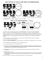
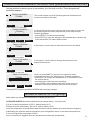
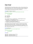
QUICK SETTING OF THE CH PUMP SWITCH-ON TEMPERATURE
CH
DHW
FHP
Press the knob
:30 Tue
16
CH
WINTER
DHW
FHP
CH
DHW
FHP
Turn the knob
to select temperaturę
(arrows are flashing)
EXIT
EDIT
EXIT
SAVE
Press SAVE
or the knob to confirm
Press EDIT
or the knob
Pressing [EXIT] restores the MAIN SCREEN without saving changes.
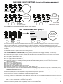
MENU OF CH PUMP PARAMETERS – "A" group
CH
DHW
:30 Tue
FHP
After pressing
MENU
A CH pump
B DHW tank
C Floor / hot water circulation pump
D Valve
E Boiler alerts
F Controller settings
WINTER
16
EXIT
Press
MENU
SELECT
Press SELECT or the knob
In order to modify CH pump parameters, press the [MENU] button. A list of groups of parameters will
appear on screen. The first selected group from top is the A group - "CH pump”. Press the [SELECT]
button or press the knob. “A1”, the first parameter from the CH pump group will be displayed. To go to the
following parameters, turn the knob right, and then press the [EDIT] button or the knob to change a desired
parameter. Now you can change the value of the parameter using the knob or dynamically alternating
buttons.
To save changes, press the [SAVE] button or press the knob. The [EXIT] button restores the previous
menu level without saving any changes.
LIST OF CH PUMP PARAMETERS (to switch between parameters and to change setting – turn the knob)
A1 CH pump switch-on temperature (1-99°C, default setting: 50°C)
A2 CH pump hysteresis (1-15°C, default setting: 2°C)
A3 Temperature of emergency CH pump switch-on in the SUMMER mode (60-99°C, default setting: 80°C.
CAUTION: SETTING THE TEMPERATURE ABOVE 90°C IS ONLY PERMITTED WHEN THE BOILER
IS ADDITIONALLY PROTECTED FROM COMING TO BOIL !
A4 CH pump control according to the temperature at the sensor behind the valve (YES, NO - default
setting: NO)
A5 Manual CH pump mode
([START] button – the pump is working regardless of the settings, [STOP] button- the pump is switched
off regardless of the settings)CAUTION: the manual mode prevails over the “anti-stop” function and the
frost protection.
When the controller is powered on the pump always switches to automated mode.
4
CONTROL OF THE HOT WATER TANK FEEDING PUMP
Installation
1. Installation of tank temperature sensor
Mount the sensor in a location recommended by the tank's manufacturer.
CAUTION: The sensor is not made for direct use in water.
2. Connecting the power cord to the pump
źConnect the yellow-green wire (zero protection) to the marked terminal of the pump.
źConnect brown and blue wires to L and N terminals of the pump.
CAUTION: The regulator must be installed by a qualified electrician only.
OPERATION OF DOMESTIC HOT WATER TANK FEEDING PUMP
The controller switches off the feeding pump of the DHW tank when temperature inside of the tank reaches
the setting displayed on the MAIN SCREEN of the controller. The pump is switched on when
the temperature falls by the setting of hysteresis (parameter B3).
The user can choose between three different hot water temperature settings: "hot", "warm" and "cold"
(parameter B1).
Temperature of hot water is programmable, different settings can be selected for every day and hour of the
week (parameter B2).
The timed programme currently in use is displayed on the MAIN SCREEN right from the DHW pump symbol:
Temperature set to "hot"
Temperature set to "warm"
Temperature set to "cold"
The user can select (or unselect) priority of domestic hot water over the operation of central and floor heating
pumps (parameter B4).
With this parameter unselected (the default setting is NO) the DHW, CH and FH pumps work independently from
each other. However, when priority has been set to YES, the CH pump and the FH pump are switched off when
the hot water tank is heating up.
The feeding pump of DHW tank switches on when the temperature set for DHW has not been achieved and
when the temperature of the CH boiler is higher than temperature of hot water by the parameter B5 ("protection
of DHW tank against cooling down").
Additional condition which must be fulfilled for the DHW pump to be switched on is that the boiler has achieved
the value set for parameter B6 - "temperature of the CH boiler at which the feeding pump of the DHW tank is
switched on".
When the SUMMER mode is activated (parameter F1), the boiler feeds only the DHW tank and hot water
circulation.
ANTIBACTERIAL PROTECTION FUNCTION
The user can select protection against Legionella bacteria in the DHW tank (parameter B7)
CAUTION: temperature of the active weekly antibacterial protection is 60°C.
In addition to selecting automatic antibacterial protection, it is possible to override settings manually to carry out
immediately a single antibacterial protection procedure.
CAUTION: For antibacterial protection procedure to be carried out the temperature of the CH boiler must achieve
at least 65°C (if that requirement has not been fulfilled, the controller will display an alert).
The maximal time of the antibacterial protection procedure is 2 hours.
If the temperature in the DHW tank reaches 60°C in a given weekly cycle the next scheduled antibacterial
protection procedure will not be carried out.
icon on the main screen means a completed antibacterial protection procedure.
In order to increase efficiency of the procedure, it is recommended to open all water discharge points
(taps and others)
5
DHW TANK - QUICK SETTING (for active timed programmes)
CH
DHW
FHP
Press the knob
:30 Tue
16
CH
WINTER
DHW
CH
FHP
DHW
FHP
Turn the knob
to select
DHW tank
Turn the knob
to set temperature
(arrows are flashing)
SAVE
EXIT
EDIT
EXIT
Press SAVE
or the knob to confirm
press EDIT
or press the knob
Pressing EXIT restores the MAIN SCREEN without saving changes.
DHW TANK PARAMETERS - group B
CH
DHW
A CH pump
B DHW tank.
FHP
C Floor / hot water circulation pump
Turn the knob
to select
DHW tank
D Valve
E Boiler alerts
F Controller settings
:30 Tue
WINTER
16
Press
MENU
EXIT
SELECT
Press SELECT or the knob
Press MENU to change parameters of the DHW tank The first group of parameters will appear on the screen Turn the knob right
(clockwise) to select group "B - DHW tank", and then press the knob or the SELECT button to confirm. The first group of parameters
("B1") will appear on the screen. Turn the knob right to go to different parameters, and then press EDIT/SELECT or the knob to
change. At this point, you can change parameter settings either by turning the knob or using the dynamically appearing buttons Some
parameters need to be selected for editing; use the SELECT button and the knob - a flashing dot will highlight the parameter selected
for editing.
Editing is confirmed by pressing the knob or the SAVE button.
Pressing EXIT restores the previous menu without saving changes.
LIST OF PARAMETER OF THE DHW TANK (moving between parameters and changing of settings - turn the knob):
B1 DHW tank temperature (on selecting, a flashing dot will indicate the edited temperature; turn the knob to move between
different temperatures)
B1a hot (10-90°C, default setting: 50°C)
B1b warm (10-90°C, default setting: 40°C)
B1c cold (10-90°C, default setting: 25°C)
B2 timed programmes of the DHW tank (described in the chapter "TIMED PROGRAMMES" on page 11)
B3 DHW tank hysteresis (on selecting, a flashing dot will indicate the edited hysteresis; turn the knob to move between
different hystereses)
B3a hot (1-15°C, default setting: 3°C)
B3b warm (1-15°C, default setting: 3°C)
B3c cold (1-15°C, default setting: 3°C)
B4 DHW tank priority YES, NO (default setting is NO)
B5 DHW tank protection from cooling down (0-15°C, default setting: 5°C)
B6 minimal temperature of the CH boiler at which the DHW tank feeding pump is switched on (20-70°C, default setting: 20°C)
B7 protection of DHW against Legionella (YES, NO; default setting: NO) CAUTION: minimal temperature of active
antibacterial protection is 60°C
The [WHEN] button opens a screen to edit the time when the weekly protection procedure is started (default setting: Sunday,
0h.00m); the [NOW] button immediately starts a single antibacterial protection procedure
CAUTION: For antibacterial protection procedure to be carried out the temperature of the CH boiler must achieve at least 65C (if
that requirement has not been not fulfilled the controller will display an alert)
If in a given weekly cycle the temperature in the DHW tank reaches 60°C, the next scheduled antibacterial protection procedure
will be skipped.
B8 manual mode of the DHW tank feeding pump. [START] button - the pump is switched on regardless of the settings; [STOP]
button - the pump is switched off regardless of the settings.
CAUTION: The manual mode overrides the "anti-stop" function and the holiday mode.
When the controller is powered on the pump always switches to automated mode.
6
CONTROL OF FLOOR HEATING/CIRCULATION PUMP
Installation instructions
1. Installation of the floor heating temperature sensor/hot water circulation temperature sensor
źWhen the "as central heating" mode of the floor heating pump is selected (parameters C4, C5) the floor heating sensor is
not in use (i.e. it is used ONLY to measure temperature, for instance of returning floor heating water - it is the
recommended solution, see diagram on page 2). In this configuration the FH pump works on the basis of the temperature
sensor of the CH boiler.
źWhen the "as domestic hot water" mode of the FH pump is selected (parameters C4, C5), the FH sensor should be
installed at the return of the floor heating water circuit.
źWhen "hot water circulation pump" mode is selected (parameter C4), the sensor should be installed at the return of the
hot water circulation circuit close to the circulation pump.
źThe sensor should be attached with two provided strips so that it adheres well to the pipe.
źIt is recommended to additionally wrap the sensor with some thermal insulation material.
CAUTION: The sensor is not made for direct use in water.
2. Connecting the power cord to the floor heating/hot water circulation pump
źConnect the yellow-green wire (zero protection) to the marked terminal of the pump.
źConnect brown and blue wires to L and N terminals of the pump.
CAUTION: The regulator must be installed by a qualified electrician only.
FLOOR HEATING PUMP IN USE (PAR C4,C5)
When the "as central heating" mode for the FH pump has been selected (recommended - see diagram on page 2),
the floor heating sensor is not in use (i.e. it is used ONLY to measure temperature, for instance of returning FH water).
The floor heating pump operates on the basis of the readings of the boiler temperature sensor. The controller switches
on the pump when the temperature in the central heating system reaches the value set for the FH pump as displayed
on the MAIN SCREEN of the controller.
If a thermostatic mixing valve has not been installed in the floor heating circuit (in this configuration installing such a
valve is not recommended), the user can select the "as domestic hot water" mode for the FH pump. - In this
configuration the temperature sensor should be installed at the return of floor heating water.
The controller switches on the FH pump when the temperature of the returning heating water reaches the setting for
the FLOOR pump as displayed on the MAIN SCREEN of the controller.
The pump is working provided that water in the CH boiler is warmer than the returning water in the floor heating
circuit.
The user can select three different temperature values for the floor heating circuit -"day", "night" and "economy"
(parameter C1). Temperature can be programmed for every day of the week and every hour (parameter C2 - timed
programmes). The timed programme in use is displayed on the MAIN SCREEN to the right of the FLOOR pump icon.
temperature of the floor
heating circuit set to "day"
temperature of the floor
heating circuit set to "night"
temperature of the floor
heating circuit set to "economy"
When DHW priority has been selected (parameter B4 is set to YES), the FH circuit pump will be switched off while
the DHW tank is heating up.
If SUMMER mode has been selected (parameter F1), the CH boiler only feeds the DHW tank.
HOT WATER CIRCULATION PUMP IN USE (PAR C4)
When "hot water circulation pump" control has been selected (parameter C4), the sensor should be installed at the
return of the circulating hot water close to the circulation pump. The controller switches on the CIR pump when the
temperature of the returning circulating water reaches the setting for the CIRCULATION pump as displayed on the
MAIN SCREEN of the controller.
The user can select three different temperatures of circulating water -"hot", "warm" and "cold" (parameter C1).
Temperatures at which the circulation pump is switched off are programmable. Different temperatures can be set for
every day of the week and every hour (parameter C2). The timed programme in use is displayed on the MAIN SCREEN
to the right of the CIR pump icon.
Circulating water
temperature set to "hot"
Circulating water
temperature set to "warm"
Circulating water
temperature set to "cold"
The circulation pump is in use provided that the temperature in the DHW tank at a given moment is at least 1°C higher
than the current setting for the circulation pump.
If SUMMER mode has been selected (parameter F1), the central heating boiler only feeds the DHW tank and hot water
circulation.
7
FLOOR CIRCUIT/HOT WATER CIRCULATION PUMP - QUICK SETTING
(for active timed programmes)
CH
DHW
FHP
Press the knob
:30 Tue
16
CH
WINTER
DHW
FHP
CH
Turn the knob
to select
floor/hot water
circulation pump
FHP
Turn the knob
to set temperature
(arrows are flashing)
EXIT
EDIT
EXIT
DHW
SAVE
Press SAVE
or the knob to confirm
press EDIT
or press the knob
Pressing EXIT restores the MAIN SCREEN without saving changes.
FLOOR CIRCUIT/HOT WATER CIRCULATION PUMP PARAMETERS - group C
CH
DHW
A CH pump
B DHW tank.
FHP
C Floor / hot water circulation pump
D Valve
E Boiler alerts
F Controller settings
:30 Tue
WINTER
16
Press
MENU
EXIT
SELECT
Turn the knob
to select
floor/hot water
circulation pump
Press SELECT or the knob
Press MENU to change parameters of the floor heating pump/hot water circulation pump. List of groups of parameters will appear on the screen. Turn the knob right
(clockwise) to select group "C - floor heating pump/hot water circulation pump", and then press the knob or the SELECT button to confirm. "C1" - first of the group of
parameters of the floor heating pump/hot water circulation pump will appear on the screen. Turn the knob right (clockwise) to go to different parameters. Press the
knob or the EDIT/SELECT button to change settings. Some parameters need to be selected for editing: use the SELECT button and the knob - a flashing dot will
highlight the parameter selected for editing. Editing is confirmed by pressing the knob or the SAVE button. Pressing EXIT restores the MAIN SCREEN without
saving changes.
LIST OF PARAMETERS WHEN THE FLOOR HEATING PUMP IS SELECTED
C1 temperature of the floor heating circuit
C1a day (1-99°C, default setting: 55°C)
C1b night (1-99°C, default setting: 50°C)
C1c economy (1-99°C, default setting: 45°C)
C2 timed programmes for floor heating (described in the chapter 'TIMED PROGRAMMES' on page 11)
C3 floor heating hysteresis
C3a day (1-15°C, default setting: 2°C)
C3b night (1-15°C, default setting: 2°C)
C3c economy (1-15°C, default setting: 2°C)
C4 Select pump
- floor pump (default setting)
- hot water circulation pump
C5 - select mode of the floor heating pump
- as CH (default setting) (the floor heating pump is switched at set temperature at the boiler sensor
- as DHW (the floor heating pump is switched off at set temperature at the floor heating circuit sensor
C6 manual mode of the pump. [START] button - the pump is switched on regardless of the settings; [STOP] - the pump is switched off regardless of the settings).
CAUTION: Manual mode overrides the "anti-stop" function and the holiday mode. When the controller is powered on the pump always switches to automated mode.
LIST OF PARAMETERS WHEN THE HOT WATER CIRCULATION PUMP IS SELECTED
C1 Hot water circulation pump switch off temperature setting
C1a hot (1-99°C, default setting: 50°C)
C1b warm (1-99°C, default setting: 40°C)
C1c cold (1-99°C, default setting: 25°C)
C2 Timed programmes for hot water circulation pump (described in the chapter 'TIMED PROGRAMMES" on page 11)
C3 Hysteresis of the hot water circulation pump
C3a hot (1-15°C, default setting: 2°C)
C3b warm (1-15°C, default setting: 2°C)
C3c cold (1-15°C, default setting: 2°C)
C4 Select pump
- floor pump (default setting)
- hot water circulation pump
C5 - circulation pump in use while DHW tank is heating up (NO, YES default setting: YES)
C6 Circulation pump - manual mode [START] button - the pump is switched on regardless of the settings; [STOP] button - the pump is switched off regardless of
the settings.
CAUTION: The manual mode overrides the "anti-stop" function and the holiday mode. When the controller is powered on the pump always switches
to automated mode
8
CONTROL OF THE MIXING VALVE
Installation
1. Installation of the temperature sensor behind the valve
Attach the sensor to an uninsulated pipe behind the valve with two provided strips so that it adheres well.
It is recommended to additionally wrap the sensor with some thermal insulation material.
CAUTION: The sensor is not made for direct use in water.
2. Connecting the power cable to the valve
źConnect the longer BLUE wire of the 3-wire valve power cable with the common (neutral) terminal on the valve
(the one marked with N).
źthe BLACK wire of the power cable carries the "valve opening" signal.
źthe BROWN wire of the power cable carries the "valve closing"signal.
It is recommended to check the connections by opening and closing the valve manually (parameter D4)
CAUTION: The regulator may be installed by a qualified electrician only.
THE MIXING VALVE IN USE
The function of the controller is to stabilise water temperature in the central heating system. This is
achieved by opening and closing of the mixing valve.
The controller switches the valve on and off in order to achieve the value set for the VALVE as displayed
on the MAIN SCREEN of the controller.
The user can select three different temperatures behind the valve -"day", "night" and "economy"
(parameter D1). Temperature behind the valve is programmable, different temperature values can be set
for every day and hour of the week (parameter D2). The timed programme in use is displayed on the
MAIN SCREEN to the right of the VALVE icon.
temperature
behind the valve "day"
temperature
behind the valve "night"
temperature
behind the valve "economic"
At the time when the temperature setting is switched from "day" to "night", from "night" to "economy" or
from "day" to "economy" the valve is continuously closed for 4 minutes The closing of the valve is
overridden when a need to open the valve arises.
The valve is continuously closed for 4 minutes when the SUMMER mode is activated.
When the SUMMER mode has been selected, the CH pump is switched on only in an emergency (a
visual and sound alert are triggered) In such a case the valve is fully opened while the CH pump is
working. The valve is continuously closed for 4 minutes after the alerts have been switched off.
The valve is fully, continuously open when temperature in the boiler reaches 92°C. A visual alert is
activated.
The user can manually open and close the valve, e.g. in order to check if it has been properly connected
(parameter D4). Press [OPEN] to open the valve, press [CLOSE] to shut off the valve.
9
TEMPERATURE BEHIND THE VALVE - QUICK SETTING
(for an activate timed programme)
CH
DHW
FHP
Press the knob
:30 Tue
16
CH
WINTER
DHW
CH
FHP
DHW
FHP
Turn the knob
to select
valve
Turn the knob
to set temperature
(arrows are flashing)
SAVE
EXIT
EDIT
EXIT
Press SAVE
or the knob to confirm
press EDIT
or press the knob
Pressing EXIT restores the MAIN SCREEN without saving changes.
MENU OF VALVE PARAMETERS – D group
CH
DHW
A CH pump
B DHW tank.
FHP
C Floor / hot water circulation pump
D Valve
E Boiler alerts
F Controller settings
:30 Tue
WINTER
16
EXIT
Turn the knob
to select
valve
SELECT
Press
MENU
Press SELECT or the knob
In order to modify valve parameters, press the [MENU] button. A list of groups of parameters will appear
on screen. Turn the knob right (clockwise) to select the D group - “Valve”. Press [SELECT] or the knob.
“D1”, the first parameter from the valve group will be displayed. To go to different parameters, turn the
knob right, and then press the [EDIT] / [SELECT] button or the knob to change a desired parameter. Now
you can change the value of the parameter using the knob or the dynamically alternating buttons.
Some parameters need to be selected for editing: use the SELECT button and the knob - a flashing dot
will highlight the parameter selected for editing. To save changes, press the [SAVE] button or press the
knob. The [EXIT] button restores the previous menu level without saving changes.
LIST OF VALVE PARAMETERS (to switch parameters and change setting – turn the knob):
D1 Temperature behind the valve (once this option has been selected, a flashing dot highlights edited
temperature; turning the knob changes temperature setting)
D1a day (1-99°C, default setting: 45°C)
D1b night (1-99°C, default setting: 30°C)
D1c economy (1-99°C, default setting: 25°C)
D2 Timed programmes for temperature behind the valve (description in section “TIMED
PROGRAMMES OPERATION” on page 11)
D3 Valve downtime (valve action time is constant - 1 sec.) (0-200 sec., default setting: 10 sec.)
D4 Manual valve mode (the [STOP] button switches off the manual mode)
10
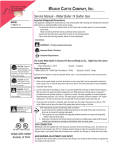
TIMED PROGRAMMES OPERATION (parameters B2,C2,D2)
Having selected a desired group of parameters, turn the knob until the “Timed programmes”
parameter appears.
... Timed programmes.. ...
Monday
time
3
6
9
12
15
18
EXIT
This screen shows a chart of timed programmes (temperatures)
for the current day of the week.
21
SELECT
Press SELECT or the knob
... Timed programmes ...
Monday
3
time
EXIT
6
9
12
15
18
COPY
21
SELECT
In this screen turn the knob to select a day of the week. You can see
the timed programmes chart (temperature) for the selected day.
Possible operations:
- press [SELECT] to edit the selected day
- press [COPY] to copy the settings for the selected day to another day
of the week which you select with the knob
Press SELECT or the knob
... Timed programmes ...
Monday
In this screen, turn the knob to select time interval to be edited.
1
EDIT
EXIT
Press EDIT or the knob
... Timed programmes ...
Monday
In this screen, turn the knob to change temperature for the
selected time interval.
1
EXIT
NEXT
Press NEXT or the knob
... Timed programmes ...
Monday
2
EXIT
SAVE
EDIT
Once you press [NEXT] or the knob, the symbol of timed
programmes moves to the following hour. Possible operations:
- press [EDIT] to change the temperature for a selected hour (see
the screen above)
- turn the knob to select any hour for editing
- press [SAVE] to save changes and return to the screen of
selection of the day of the week (see the second screen).
Pressing [EXIT] restores the MAIN SCREEN without saving changes.
BOILER ALERTS – E group
Boiler alerts are managed like parameters in MENU groups A to D.
CH BOILER ALERTS (to switch parameters and change setting – turn the knob):
E1Low CH boiler temperature. (0-50°C, default setting: 8°C)
E2High CH boiler temperature. (60-120°C, default setting: 92°C)
Once the temperature exceeds the set alert threshold, both the audible and visual alerts are triggered.
Additionally, the controller features permanent (non-configurable) alerts: for low boiler temperature at
8°C and of high boiler temperature at 92°C.
Only a visual alert is triggered when the temperature exceeds the set threshold.
11
CONTROLLER SETTINGS - group F
Controller settings are managed like parameters in MENU groups A to D.
CONTROLLER SETTINGS (moving between parameters and change of setting - turn the knob):
F1 Season of the year SUMMER, WINTER (factory setting: WINTER) The selected season is displayed
on the MAIN SCREEN.
F2 Holiday mode (1-28 days, default setting: 0 days = switched off) - over the selected period of time all
economic settings are active. "The text string "HOLIDAY MODE" will appear on the MAIN SCREEN
instead of settings.
Press the [START] button to switch on the holiday mode for the number of days selected with the
knob, press the [STOP] button to switch off.
F3 Day of the week/hour (press the NEXT button or the knob to select day of the week, hour and minutes
for edition).
F4 Time until the main screen is returned (10-240 secs, default setting: 60 secs) CAUTION - the
controller does not return automatically to the MAIN SCREEN from "manual mode" menus.
F5 Brightness after the main screen is returned (0-100%, default setting: 20%).
F6 Return to default settings (the controller will ask to confirm).
CAUTION: return to default settings does not concern display contrast (parameter F8).
F7 Information about the controller (model, software version 2.1 - 4.0) - read only.
F8 Contrast of the display (1-31, default setting: 12 - CAUTION: return to default settings does not
concern display contrast).
KIT COMPOSITION
ź controller
ź fixing clips – 6 pcs.
ź wall mount – 1 pc.
ź rawl plugs 6mm – 2 pcs.
ź support – 1 pc. (available as an option at an extra charge)
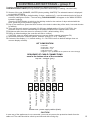
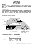
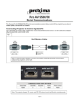
SEQUENCE OF CABLE CONNECTIONS
seen in the bottom view of the controller
Sensor behind the valve
(length: 2m) - green
Valve (length: 2m)
Floor heating/circulation sensor
(length: 5m)- red
Floor heating/circulation
pump (length: 2m)
DHW tank sensor
(length: 3m) - yellow
DHW tank pump
(length: 2m)
CH pump (length: 2 m)
Mains 230V (length: 1.5m)
CH boiler sensor
(length: 2m) -black
top row – sensors (gray)
Bottom row - power supply cables (black)
CAUTION
In case any of the appliances is not connected, you must not remove the protective sheath from the
cable end. The cable should be coiled up and secured with a fixing clip.
12
PROTECTION
The pumps, valve and controller are secured with a 3.15A fuse which blows up in the event of
electric failure (such as a short circuit in one of the pumps, the valve or the controller).
WARRANTY
TMK sp.j. grants the user a warranty for the JOKER Z3P controller. The warranty period is 3
years from the date of purchase of the device, however not longer than 4 years from the date of
manufacture.
WARRANTY TERMS AND CONDITIONS
Warranty claims shall be accepted provided that the terms and conditions of warranty, and general
rules of operation of electronic devices, are complied with as required. TMK sp.j. guarantees
appropriate workmanship, high quality and reliable operation of the controller. In the event of any
faults in the controller's operation, or defects which can be attributed to the manufacturer, TMK sp.j.
shall repair or replace the faulty controller with a defect-free device within 14 working days from the
date of returning the controller (in person or through post). The warranty scheme explicitly excludes
all defects arising due to the user's fault and, particularly, defects caused by mechanical damage,
faulty mounting, water ingress or operation of the device contrary to the general rules of operation of
electronic devices.
The warranty is only valid with a proof of purchase.
DATE OF SALE: ....................................
day, month, year
.....................................
Seller's stamp and signature
..........................
DATE OF MANUFACTURE
MANUFACTURER:
TMK sp.j.
62-300 Września
Szosa Witkowska 105
tel./fax +48 61 437 97 60
www.tmk.com.pl
13