1
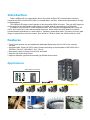
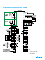
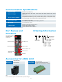
Automation for a Changing World
Delta EtherCAT Interface
Servo Drive
ASDA A2-E Series
www.deltaww.com
Introduction
Delta’s ASDA A2-E, an advanced AC Servo Drive with an EtherCAT communication interface,
complies with IEC61158 and IEC61800-7 to enable faster, real-time, and accurate performance in highend applications.
The ASDA A2-E follows in the footsteps of the successful ASDA-A2 series. This new A2-E supports
all the modes of the CoE device profile based on CiA402, and all command types of EtherCAT.
In addition to the EtherCAT communication function, A2-E features the integrated Safe Torque Off
(STO), short cycle time, and extension digital input port, which makes the A2-E ideal for multi-axis
synchronization applications in a wide range of machinery automation fields. This series covers a wide
range of rated power to drive the motors, from 400W to 7.5kW for 400V and 100W to 3kW for 220V.
Features
■ Touch probe function can be enabled with dedicated Digital Input (DI) on CN7 or the external
encoder.
■ Integrated Safe Torque Off (STO) safety function according to the standards of IEC61508, SIL2 ;
IEC62061, SILCL2 ; ISO13849-1, Cat. 3 PL=d
■ Wide power range coverage in both 220V and 400V
■ Supports full-closed loop control
■ Supports absolute type and incremental type ECMA series motors
Applications
EtherCAT controllers
Third party controllers
Delta’s controller
1
Specifications of ASDA A2-E_220V Series
Phase / Voltage
400W
750W
04
07
Three-phase / Single-phase 220VAC
Permissible Voltage Range
Three-phase / Single-phase 200 ~ 230VAC , -15%~10%
ASDA A2-E Series
Power
Supply
Input Current (3PH) Unit: Arms
Input Current (1PH) Unit: Arms
Continuous Output Current Unit: Arms
Cooling Method
Encoder Resolution
(Servo Drive Resolution)
Control of Main Circuit
Tuning Modes
Dynamic Brake
Command Source
Position
Smoothing Strategy
Control
Electronic Gear
Torque Limit Operation
Mode
Feed Forward
(CSP)
Compensation
Speed Control Range*1
Speed
Control
Mode
(CSV)
Torque
Control
Mode
(CST)
Digital
0.39
0.69
0.9
200W
02
1.11
1.86
1.92
3.22
1.55
2.6
Natural Air Circulation
3.66
6.78
5.1
1kW
10
4.68
8.88
7.3
1.5kW
15
5.9
10.3
8.3
Fan Cooling
SVPWM (Space Vector Pulse Width Modulation) Control
Auto / Manual
Built-in
External analog signal
Low-pass and P-curve filter
Electronic gear N/M multiple N: 1 ~ 32767, M: 1 : 32767 (1/50 < N/M < 25600)
External analog signal
External analog signal / Internal parameters
1:5000
1:3000
External analog signal
Smoothing Strategy
Torque Limit Operation
Frequency Response
Characteristic
Low-pass and S-curve filter
Set by parameters or via analog input
Speed Accuracy
(at rated rotation speed)*2
0.01 % or less at 0 to 100 % load fluctuation
0.01 % or less at 0℃ to 50℃ ambient temperature fluctuation
Feed Forward
Compensation
0.01 % or less at ±10 % power fluctuation
Command Source
External analog signal
Smoothing Strategy
Low-pass filter
Speed Limit Operation
Via analog input
Inputs
Inputs/
Outputs
Protective Functions
Communication Interface
Installation Site
Altitude
Atmospheric Pressure
Operating Temperature
Storage Temperature
Humidity
Vibration
IP Rating
Power System
2kW
3kW
20
30
Three-phase 220VAC
Three-phase
200 ~ 230VAC ,
-15% ~ 10%
8.76
9.83
13.4
19.4
Incremental type: 20-bit;Absolute type: 17-bit
Command Source External
Analog Signal
Outputs
Environment
100W
01
Maximum 1 kHz
Servo on, Reset, Gain switching, Pulse clear, Zero speed CLAMP, Command input reverse control, Command triggered,
Speed/Torque limit enabled, Position command selection, Motor stop, Speed position selection, Position / Speed mode
switching, Speed / Torque mode switching, Torque / Position mode switching, PT / PR command switching, Emergency
stop, Forward / Reverse inhibit limit, Reference “Home” sensor, Forward / Reverse operation torque limit, Move to
“Home”, Electronic Cam (E-Cam), Forward / Reverse JOG input, Event trigger PR command, Electronic gear ratio
(Numerator) selection and Pulse inhibit input
Encoder signal output (A, B, Z Line Driver and Z Open Collector )
Servo ready, Servo on, At Zero speed, At Speed reached, At Positioning completed, At Torques limit, Servo alarm (Servo
fault) activated, Electromagnetic brake control, Homing completed, Output overload warning, Servo warning activated,
Position command overflow, Forward / Reverse software limit, Internal position command completed, Capture operation
completed output., Motion control completed output., Master position of E-Cam (Electronic Cam)
Overcurrent, Overvoltage, Undervoltage, Motor overheated, Regeneration error, Overload, Overspeed, Abnormal pulse
control command, Excessive deviation, Encoder error, Adjustment error, Emergency stop activated, Reverse/ Forward
limit switch error, Position excessive deviation of full-close control loop, Serial communication error, Input power phase
loss, Serial communication time out, short circuit protection of U, V, W, and CN1, CN2, CN3 terminals
USB / EtherCAT
Indoor location (free from direct sunlight), no corrosive liquid and gas
(far away from oil mist, flammable gas, dust)
Altitude 1000 m or lower above sea level
86kPa ~ 106kPa
0℃ ~ 55℃ (If operating temperature is above 45℃ , forced cooling will be required)
-20℃ ~ 65℃
0 ~ 90% RH (non-condensing)
9.80665 m/s2 (1 G) less than 20 Hz, 5.88 m/s2 (0.6 G) 20 to 50 Hz
IP20
TN System*3
IEC/EN 61800-5-1, UL 508C, C-tick
Approvals
Footnote:
*1 Rated rotation speed: When full load, speed ratio is defined as the minimum speed (the motor will not pause).
*2 When command is rated rotation speed, the speed fluctuation rate is defined as: (Empty load rotation speed – Full load rotation speed) / Rated rotation speed
*3 TN system: A power distribution system having one point directly earthed, the exposed conductive parts of the installation being connected to that point
by a protective earth conductor.
2
Specifications of ASDA A2-E_400V Series
ASDA A2-E Series
Power
Supply
Main
Circuit
Power
Input Voltage
Input Current
Input Power
Permissible Voltage Range
Input Current Unit: Arms
Continuous Output Current
Unit: Arms
Cooling Method
Encoder Resolution
(Servo Drive Resolution)
Control of Main Circuit
Tuning Modes
Dynamic Brake
Position
Command Source
Smoothing Strategy
Control
Electronic Gear
Mode
Torque Limit Operation
750W
07
1kW
10
Speed
Control
Mode
(CSV)
3kW
30
4.5kW
45
1.40
2.35
3.02
2.0
3.35
3.52
5.02
6.66
11.9
14.1
17.27
20
22.37
30
Fan Cooling
Incremental type: 20-bit ;Absolute type: 17-bit
SVPWM (Space Vector Pulse Width Modulation) Control
Auto / Manual
Built-in
External analog signal
Low-pass and P-curve filter
Electronic gear N/M multiple N: 1 ~ 32767, M: 1 : 32767 (1/50 < N/M < 25600)
External analog signal
External analog signal / Internal parameters
1:5000
1:3000
External analog signal
Low-pass and S-curve filter
Set by parameters or via analog input
Maximum 1 kHz
Command Source
External analog signal
Smoothing Strategy
Low-pass filter
Speed Limit Operation
Outputs
Outputs
Protective Functions
Communication Interface
Installation Site
Altitude
Atmospheric Pressure
Operating Temperature
Storage Temperature
Humidity
Vibration
IP Rating
Power System
7.5kW
75
11.9
Feed Forward Compensation
Inputs/
5.5kW
55
1.66 A
39.85 W
0.01 % or less at 0 to 100 % load fluctuation
0.01 % or less at 0℃ to 50℃ ambient temperature fluctuation
0.01 % or less at ±10 % power fluctuation
Inputs
Digital
2kW
20
1.18 A
28.2 W
Three-phase, 380~480VAC, ±10%
4.24
5.65
8.01
Speed Control Range*1
Command Source External
Analog Signal
Smoothing Strategy
Torque Limit Operation
Frequency Response
Characteristic
Speed Accuracy
(at rated rotation speed)*2
Torque
Control
Mode
(CST)
1.5kW
15
24VDC, ±10%
0.43 A
10.32 W
Feed Forward Compensation
(CSP)
Environment
400W
04
Via analog input
Servo on, Reset, Gain switching, Pulse clear, Zero speed CLAMP, Command input reverse control, Command
triggered, Speed/Torque limit enabled, Position command selection, Motor stop, Speed position selection, Position
/ Speed mode switching, Speed / Torque mode switching, Torque / Position mode switching, PT / PR command
switching, Emergency stop, Forward / Reverse inhibit limit, Reference “Home” sensor, Forward / Reverse operation
torque limit, Move to “Home”, Electronic Cam (E-Cam), Forward / Reverse JOG input, Event trigger PR command,
Electronic gear ratio (Numerator) selection and Pulse inhibit input
Encoder signal output (A, B, Z Line Driver and Z Open Collector )
Servo ready, Servo on, At Zero speed, At Speed reached, At Positioning completed, At Torques limit, Servo alarm
(Servo fault) activated, Electromagnetic brake control, Homing completed, Output overload warning, Servo warning
activated, Position command overflow, Forward / Reverse software limit, Internal position command completed,
Capture operation completed output., Motion control completed output., Master position of E-Cam (Electronic Cam)
Overcurrent, Overvoltage, Undervoltage, Motor overheated, Regeneration error, Overload, Overspeed, Abnormal
pulse control command, Excessive deviation, Encoder error, Adjustment error, Emergency stop activated, Reverse/
Forward limit switch error, Position excessive deviation of full-close control loop, Serial communication error, Input
power phase loss, Serial communication time out, short circuit protection of U, V, W, and CN1, CN2, CN3 terminals
USB / EtherCAT
Indoor location (free from direct sunlight), no corrosive liquid and gas
(far away from oil mist, flammable gas, dust)
ltitude 1000 m or lower above sea level
86kPa ~ 106kPa
0℃ ~ 55℃ (If operating temperature is above 45℃ , forced cooling will be required)
-20℃ ~ 65℃
0 ~ 90% RH (non-condensing)
9.80665 m/s2 (1 G) less than 20 Hz, 5.88 m/s2 (0.6 G) 20 to 50 Hz
IP20
TN System*3
IEC/EN 61800-5-1, UL 508C, C-tick
Approvals
Footnote:
*1 Rated rotation speed: When full load, speed ratio is defined as the minimum speed (the motor will not pause).
*2 When command is rated rotation speed, the speed fluctuation rate is defined as: (Empty load rotation speed – Full load rotation speed) / Rated rotation speed
*3 TN system: A power distribution system having one point directly earthed, the exposed conductive parts of the installation being connected to that point by a protective earth conductor.
3
EtherCAT Communication Mode
*1
Wiring for 220V
*2
Wiring for 400V
Note :
*1. 400W and below drives do not provide
built-in regenerative resistor.
*2. The brake coil has no polarity.
*3. For wiring diagrams of other control
modes, please refer to the user manual of
Delta's ASDA A2-E.
4
Communication Specifications
Physical Layer
IEEE802.3u (100 BASE-TX)
Data Link Layer
APRD, FPRD, BRD, LRD, APWR, FPWR, BWR, LWR, ARMW, FRMW, APRW, FPRW,
BRW, LRW
Device Profile (CiA402)
Homing Mode, Profile Position Mode, Profile Velocity Mode, Profile Torque Mode,
Interpolated Position Mode, Cyclic Syn. Position Mode, Cyclic Syn. Velocity Mode, Cyclic
Syn. Torque Mode, Touch Probe Function, Torque Limit Function
Process Data Size
Tx: 8 Object (32 byte, Max.);
Rx: 8 Object (32 byte, Max.) Dynamic Mapping supported.
Bus Clock
DC cycle with min. 250 us*
LED Indicator
EtherCAT Link/Activity Indicator (L/A) x 2
EtherCAT RUN Indicator (RUN) x 1
EtherCAT ERROR Indicator (ERR) x 1
* This function will be available in a new version soon to come.
Part Names and
Functions
Ordering Information
ASD - A2 - 04
Servo Status Display /
Operation Panel /
Charge LED
External Encoder
Extension DI Port
21 - E
EtherCAT model
Series: A2
Product Name:
AC Servo Drive
CN1 26 Pin I/O
Input Voltage and Phase
21: 220V 1-phase / 3-phase
23: 220V 3-phase
43: 400V 3-phase
Rated Output Power
01: 100W
15: 1.5kW
02: 200W
20: 2kW
04: 400W
30: 3kW
07: 750W
45: 4.5kW
10: 1kW
55: 5.5kW
Motor Encoder
EtherCAT Status LED
Safe Torque Off
(STO) I/O
EtherCAT Port
USB Port
Accessories for ASDA A2-E
Part Number
ASD-CNSC0026
Part Number
ASD-CNFS0808
Description
CN1 connector
Description
Pack of connectors used for STO
wiring, 8 pcs of connectors in one pack
Note :
For other accessories, please refer to Delta's ASDA-A2 product catalogue.
5
Dimensions
45(1.77)
0)
70(2.76)
0.2
.2(
Ø5
u 400V Series
400W / 750W / 1kW / 1.5kW
65 (2.55)
170(6.69)
163(6.42)
173(6.81)
5.5(0.22)
u 220V Series
100W / 200W / 400W
12(0.47)
163
(6.41)
12.5
(0.49)
27.5(1.08)
70 (2.75)
180 (7.08)
173
(6.81)
47 (1.85)
SCREW: M4×0.7
MOUNTING SCREW TORQUE:14(kgf-cm)
Weight
1.5(3.3)
Weight
Weight
2.0(4.4)
2kW / 3kW / 4.5kW / 5.5kW
750W / 1kW / 1.5kW
5.4(0.21)
123.5 (4.86)
5
.
Ø5
70(2.76)
12.5(0.49)
70.2
(2.76)
205.5 (8.09)
180(7.09)
173(6.81)
163(6.42)
65(2.56)
.
(0
8
(0.31)
107 (4.21)
)
7
21
230
(9.05)
47(1.85)
7
(0.27)
245
(9.64)
107
(4.21)
SCREW: M4×0.7
MOUNTING SCREW TORQUE:14(kgf-cm)
Weight
2.0(4.4)
Weight
7.5kW
5.4(0.21)
2kW / 3kW
82.0(3.23)
4.6(10.1)
2)
.2
(0
5
5.
70(2.76)
136 (5.35)
119.5 (4.70)
203.0(7.99)
70.2
(2.76)
8
205.5
(8.09)
Ø
14.5(0.57)
215.5(8.48)
203.0(7.99)
232
(9.13)
245
(9.64)
260
(10.23)
254.2
(10.00)
62.0(2.44)
5
(0.19)
107 (4.21)
PE TERMINAL
SCREW: M4×0.7
MOUNTING SCREW TORQUE:14(kgf-cm)
Weight
Weight
2.89(6.36)
5.5(12.1)
Footnote:
1. Dimensions are in millimeters (inches); Weights are in kilograms (kg) and pounds (lbs)
2. Dimensions and weights of the servo drive may be revised without prior notice.
6
Industrial Automation Headquarters
Delta Electronics, Inc.
Taoyuan Technology Center
18 Xinglong Road, Taoyuan District,
Taoyuan City 33068, Taiwan (R.O.C.)
TEL: 886-3-362-6301 / FAX: 886-3-371-6301
Asia
Delta Electronics (Jiangsu) Ltd.
Wujiang Plant 3
1688 Jiangxing East Road,
Wujiang Economic Development Zone
Wujiang City, Jiang Su Province, P.R.C. 215200
TEL: 86-512-6340-3008 / FAX: 86-769-6340-7290
Delta Greentech (China) Co., Ltd.
238 Min-Xia Road, Pudong District,
ShangHai, P.R.C. 201209
TEL: 86-21-58635678 / FAX: 86-21-58630003
Delta Electronics (Japan), Inc.
Tokyo Office
2-1-14 Minato-ku Shibadaimon,
Tokyo 105-0012, Japan
TEL: 81-3-5733-1111 / FAX: 81-3-5733-1211
Delta Electronics (Korea), Inc.
1511, Byucksan Digital Valley 6-cha, Gasan-dong,
Geumcheon-gu, Seoul, Korea, 153-704
TEL: 82-2-515-5303 / FAX: 82-2-515-5302
Delta Electronics Int’l (S) Pte Ltd.
4 Kaki Bukit Ave 1, #05-05, Singapore 417939
TEL: 65-6747-5155 / FAX: 65-6744-9228
Delta Electronics (India) Pvt. Ltd.
Plot No 43 Sector 35, HSIIDC
Gurgaon, PIN 122001, Haryana, India
TEL : 91-124-4874900 / FAX : 91-124-4874945
Americas
Delta Products Corporation (USA)
Raleigh Office
P.O. Box 12173,5101 Davis Drive,
Research Triangle Park, NC 27709, U.S.A.
TEL: 1-919-767-3800 / FAX: 1-919-767-8080
Delta Greentech (Brasil) S.A.
Sao Paulo Office
Rua Itapeva, 26 - 3° andar Edificio Itapeva One-Bela Vista
01332-000-São Paulo-SP-Brazil
TEL: 55 11 3568-3855 / FAX: 55 11 3568-3865
Europe
Deltronics (The Netherlands) B.V.
Eindhoven Office
De Witbogt 20, 5652 AG Eindhoven, The Netherlands
TEL: 31-40-2592850 / FAX: 31-40-2592851
*We reserve the right to change the information in this catalogue without prior notice.
DELTA_IA-ASDA_ASDA A2-E_C_EN_20150703