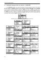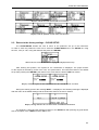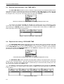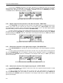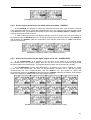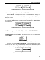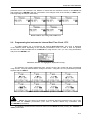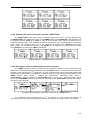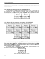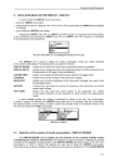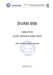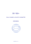
1
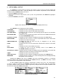
SVAN 953 USER MANUAL
9
SETUP MENU - SETUP
The SETUP list contains different sub-lists and positions. Some of them are directly related with
sound measurements and some - with the settings of the hardware components of the instrument.
In order to open the SETUP list the user has to:
• press the <MENU> push-button,
• select from the main list, using the <>, <> (or <>, <>) push-buttons, the SETUP text (highlight it
inversely),
• press the <ENTER> push-button.
Display in the main list; the SETUP text highlighted (displayed inversely)
In the SETUP list, the following items are available:
LANGUAGE
it enables the user to set language of the user interface.
CLEAR SETUP
it enables the user to return to the default, factory setup.
DAY TIME LIMITS
it enables the user to select the hours limiting day and night for the calculation
of the Lden result.
EXPOSURE TIME
it enables the user to define the exposure time used for the LEPd measurement
and other DOSE METER results.
EXTERNAL I/O SETUP
it enables the user to select the available functionality of the Ext. I/O port.
MICROPHONE
it enables the user to set on or off the compensation filter and/or outdoor filter
and select in the latter case its type.
RMS INTEGRATION
it enables the user to select the way of integration for the “family”
of the LEQ measurements.
RS232
it enables the user to set the transmission speed and the timeout in the RS232
interface.
RTC
it enables the user to set the Real Time Clock.
SHIFT MODE
it enables the user to set the operating mode of the <SHIFT> and
the <START / STOP> push-buttons.
STATISTICAL LEVELS it enables the user to select ten statistic levels to be displayed in one profile and
3 PROFILES modes and saved in the files with the main results.
TIMER
it enables the user to set the Timer function.
USB–HOST PORT
it enables the user to select the available functionality of the USB Host port.
WARNINGS
it enables the user to switch on or off the warnings that can be displayed during
the operation of the instrument.
Pressing the <SHIFT> and <> (or <SHIFT> and <>) push-buttons results in a movement
to the first position of the opened list and pressing the <SHIFT> and <> (or <SHIFT> and <>) – results
in a movement to the last position of the opened list.
In each available position any change is performed by means of the <>, <> push-buttons.
In order to confirm the selection the <ENTER> push-button has to be pressed. After this confirmation
the opened window or list is closed. In order to ignore any changes made in the opened window or list
the user has to press the <ESC> push-button.
SETUP list of the instrument
9-1
SVAN 953 USER MANUAL
9.1
_
Setting the language of the user interface - LANGUAGE
The LANGUAGE enables one to select the language of the user interface. In order to enter the list
one has to press the <ENTER> push-button on the inversely displayed LANGUAGE text of the SETUP
list. The selection is made by placing a special character by means of the <>, <> push-buttons
in the line with the selected language. Pressing the <SHIFT> and <> (or <SHIFT> and <>) pushbuttons results in a movement to the first position of the opened list and pressing the <SHIFT> and <>
(or <SHIFT> and <>) – results in a movement to the last position of the opened list. The selection
is confirmed and the list is closed after pressing the <ENTER> push-button. The list is closed without any
confirmation after pressing the <ESC> push-button.
SETUP list, the LANGUAGE text highlighted (displayed inversely)
Language windows with all available languages
Displays with the English version of the user interface
Displays with the Italian version of the user interface
Displays with the Polish version of the user interface
Displays with the Hungarian version of the user interface
Displays with the Flemish version of the user interface
9-2
SVAN 953 USER MANUAL
Displays with the French version of the user interface
Displays with the Spanish version of the user interface
9.2
Return to the factory settings - CLEAR SETUP
The CLEAR SETUP enables the user to return to the producer’s set up of the instrument.
In order to enter the position the user has to select the CLEAR SETUP text in the SETUP list, using
the <>, <> (or <>, <>) push-buttons and press the <ENTER>.
SETUP list, the CLEAR SETUP text highlighted (displayed inversely)
After entering this position, the request for the confirmation is displayed. The proper answer
for the request is selected by means of the <>, <> push-buttons. The instrument returns to the default
set up after pressing the <ENTER> push-button in the case when the answer YES was chosen.
Displays with the request for the confirmation for the CLEAR SETUP execution
During the clearing process the message WAIT... is displayed. The following message is displayed
after the return to the default settings and the instrument waits for the user’s reaction.
Displays during and after the execution of the CLEAR SETUP function
The window is closed and the instrument returns to the SETUP list after pressing any push-button
with an exception of the <SHIFT> and the <ALT> one.
9-3
SVAN 953 USER MANUAL
9.3
_
Day time limits selection - DAY TIME LIMITS
The DAY TIME LIMITS enables the user to select the required by the local standards determination
of the day and night. These limits are used for the calculation of the Lden function (cf. App. D for the
definition). In order to enter the window the user has to select the DAY TIME LIMITS text in the SETUP
list, using the <>, <> (or <>, <>) push-buttons and press the <ENTER>.
SETUP list with the DAY TIME LIMITS text highlighted (displayed inversely)
Two options are available: 6H–18H and 7H–19H. The required limits can be selected by means
of the <>, <> push-buttons. The window is closed and the instrument returns to the SETUP list
after pressing the <ENTER> (with the confirmation of a change made in the position) or <ESC> pushbutton (ignoring a change made in the position).
Displays with the available DAY TIME LIMITS
9.4
Exposure time setting - EXPOSURE TIME
The EXPOSURE TIME enables the user to set the desired value of the exposure time that
is used for the calculation of different DOSE METER functions as well as LEPd that is also calculated
in the LEVEL METER mode (cf. App. D for the definitions of the functions). In order to enter the window
the user has to select the EXPOSURE TIME text in the SETUP list, using the <>, <> (or <>, <>)
push-buttons and press the <ENTER>.
SETUP list with the EXPOSURE TIME text highlighted (displayed inversely)
The EXPOSURE TIME values are within the range [00h01, 08h00]. The required value can be set
using the <>/ <>push-buttons – after each pressing the exposure time is decremented / incremented
by one second. The step can be decremented / incremented up to 30 minutes after pressing the <>/
<> push-buttons together with <SHIFT> one.
The window is closed and the instrument returns to the SETUP list after pressing the <ENTER>
(with the confirmation of a change made in the position) or <ESC> push-button (ignoring a change made
in the position).
EXPOSURE TIME windows
9-4
SVAN 953 USER MANUAL
EXPOSURE TIME windows (cont.)
9.5
Available parameters of the Ext. I/O port selection - EXTERNAL I/O SETUP
The EXTERNAL I/O SETUP enables the user to select the available functionality of the Ext. I/O
port. In order to enter the window the user has to select the EXTERNAL I/O SETUP text in the SETUP list,
using the <>, <> (or <>, <>) push-buttons and press the <ENTER> one.
SETUP list, the EXTERNAL I/O SETUP text highlighted
In order to select a value in a position of the sub-list the <>, <> should be pressed.
The position of the sub-list is changed after pressing the <>, <> push-buttons. In order to confirm
the selection the <ENTER> push-button has to be pressed. Such pressing closes the sub-list.
After pressing the <ESC> push-button the sub-list is also closed but all changes, which were made, are
ignored.
9.5.1
Mode selection of the Ext. I/O port - MODE
In the MODE, it is possible to select the function of the instrument’s socket named as Ext. I/O.
This socket can be used as
• the output of the analogue signal (ANALOG OUT) transmitted from the input of the instrument to its
output without any digital processing (i.e. filtering),
• the input of the digital signal used as an external trigger to start the measurements (DIGITAL IN) in the
“slave” instrument,
• the digital output (DIGITAL OUT) used for triggering other “slave” instrument from the “master” one,
• the source of any alarm signal in the case of certain circumstances occurred during the measurements
(i.e. the level of the input signal was higher than selected one).
The more detailed description of the Ext. I/O is given in App. C.
To select the mode, the user has to use the <>, <> push-buttons in the line with the MODE text.
The window is closed and the instrument returns to the SETUP list after pressing the <ENTER> (with the
confirmation of all changes made there) or <ESC> push-button (ignoring all changes).
EXTERNAL I/O SETUP windows; the MODE selection
9-5
SVAN 953 USER MANUAL
_
In the case of DIGITAL IN selection the signal appearing on the Ext. I/O socket will be treated
as the external trigger if the EXT. I/O is chosen (path: INPUT/ TRIGGER SETUP/ MEASURE TRIGGER /
SOURCE / EXT. I/O) and it can be set only if SLOPE + or SLOPE – was set as a TRIGGER (path: INPUT
/ TRIGGER SETUP / MEASURE TRIGGER / TRIGGER).
MEASURE TRIGGER windows; the SOURCE selection
9.5.2
Digital output function selection of the Ext. I/O socket - FUNCTION
In the FUNCTION, it is possible to set the function of the digital output of the Ext. I/O instrument’s
socket. The socket can be used as the source of the trigger pulse (TRIG. PULSE) which starts
the measurement in another “slave” instrument linked to the “master” one or the alarm signal appears
there after fulfilling certain measurement conditions (ALARM PULSE).
In order to select the function of the digital output the user has to use the <>, <> push-buttons in
the active line with the FUNCTION text. The window is closed and the instrument returns to the SETUP
list after pressing the <ENTER> (with the confirmation of all changes made there) or <ESC> push-button
(ignoring all changes).
EXTERNAL I/O SETUP windows; the FUNCTION selected
9.5.3
Polarisation selection of the digital output signal - POLARISATION
In the POLARISATION, it is possible to select which polarisation of the signal (negative or positive)
will be valid.
In order to select the polarisation the user has to use the <>, <> push-buttons in the active line
with the POLARISATION text. The window is closed and the instrument returns to the SETUP list
after pressing the <ENTER> (with the confirmation of all changes made there) or <ESC> push-button
(ignoring all changes).
EXTERNAL I/O SETUP windows; the POLARISATION selection
9.5.4
Active level selection of the digital output signal - ACTIVE LEVEL
In the ACTIVE LEVEL, it is possible to select which level of the signal should be treated as a valid
one (“negative” or “positive” logic).
In order to select the level the user has to use the <>, <> push-buttons in the active line
with the ACTIVE LEVEL text. The window is closed and the instrument returns to the SETUP list
after pressing the <ENTER> (with the confirmation of all changes made there) or <ESC> push-button
(ignoring all changes).
9-6
SVAN 953 USER MANUAL
EXTERNAL I/O SETUP windows; the ACTIVE LEVEL selection
9.5.5
Source signal selection for the alarm pulse generation - SOURCE
In the SOURCE, it is possible to select the measurement result which level should be checked.
If the measured result level is greater than selected alarm level – the instrument will generate alarm signal
on the Ext. I/O socket. The measurement results from the first profile: PEAK(1), SPL(1) or LEQ(1) can be
used for the purpose described above.
In order to select the function of the digital output the user has to use the <>, <> push-buttons in
the active line with the SOURCE text. The window is closed and the instrument returns to the SETUP list
after pressing the <ENTER> (with the confirmation of all changes made there) or <ESC> push-button
(ignoring all changes).
EXTERNAL I/O SETUP windows; the SOURCE selection
9.5.6
Alarm level selection on the digital output of Ext. I/O - ALARM LEVEL
In the ALARM LEVEL, it is possible to set the level of the result to be monitored during
the measurements. If the result is greater than the one set in this line, the instrument will generate
the alarm signal in the selected logic. The available levels are within the range [30.0 dB, 140 dB].
The ALARM LEVEL current value decreasing / increasing by 0.1 dB is possible by means
of the <>/ <> push-buttons. The step can be decreased / increased up to 1 dB after pressing
simultaneously the <>/ <>push-buttons with the <SHIFT> one. The window is closed and
the instrument returns to the SETUP list after pressing the <ENTER> (with the confirmation of all changes
made in the window) or <ESC> push-button (ignoring all changes).
EXTERNAL I/O SETUP windows; the ALARM LEVEL setting
9-7
SVAN 953 USER MANUAL
9.6
_
Selection of the microphone parameters - MICROPHONE
The MICROPHONE enables the user to set on or off the compensation filter and/or outdoor filter
and select in the latter case its type. In order to enter the window the user has to select
the MICROPHONE text in the SETUP list, using the <>, <> (or <>, <>) push-buttons and press the
<ENTER> one.
SETUP list, the MICROPHONE text highlighted (displayed inversely)
In order to select a value in a position of the sub-list the <>, <> should be pressed.
The position of the sub-list is changed after pressing the <>, <> push-buttons.
In order to confirm the selection the <ENTER> push-button has to be pressed. Such pressing
closes the sub-list. After pressing the <ESC> push-button the sub-list is also closed but all changes, which
were made, are ignored.
9.6.1
Switching on or off the compensation filter - COMPENSATION
In the COMPENSATION, it is possible to switch on or off the compensating filter, which
was designed taking into account the average frequency characteristic of the microphones supplied
with the instrument. The frequency characteristic of the designed filter is given in App. D. This filter
compensates the non-linearity of the microphone’s frequency characteristic.
In order to switch the filter on the user has to place, by means of the <>, <> push-buttons,
the special character in the line with the COMPENSATION text.
The window is closed and the instrument returns to the SETUP list after pressing the <ENTER>
(with the confirmation of all changes made there) or <ESC> push-button (ignoring all changes).
MICROPHONE windows; the activation of the COMPENSATION filter
9.6.2
Switching on or off the outdoor filter - OUTDOOR FILTER
In the OUTDOOR FILTER, it is possible to switch on or off the compensating filter, which
was designed taking into account the average frequency characteristic of the microphones supplied
with the instrument working with the special waterproof screen used in the permanent monitoring
environmental or airport applications.
In order to switch the filter on the user has to place, by means of the <>, <> push-buttons,
the special character in the line with the OUTDOOR FILTER text.
The window is closed and the instrument returns to the SETUP list after pressing the <ENTER>
(with the confirmation of all changes made there) or <ESC> push-button (ignoring all changes).
9-8
SVAN 953 USER MANUAL
MICROPHONE windows; the activation of the OUTDOOR FILTER
9.6.3
Selection the type of the outdoor filter - FILTER TYPE
In the FILTER TYPE, it is possible to select the type of the compensating filter, which has to be
used in the permanent outdoor monitoring application. The characteristics of the outdoor filters depend on
the application: environmental (the acoustic signal is perpendicular to the microphone’s grid) or airport
(the acoustic signal is parallel to the microphone’s grid). The frequency characteristic of the designed
filters is given in App. D.
The selection is possible by means of the <>, <> push-buttons pressed in the active line
with the FILTER TYPE text. The window is closed and the instrument returns to the SETUP list
after pressing the <ENTER> (with the confirmation of all changes made there) or <ESC> push-button
(ignoring all changes).
MICROPHONE windows; the activation of the OUTDOOR FILTER
9.7
Detector’s type selection in the LEQ calculations - RMS INTEGRATION
The RMS INTEGRATION enables the user to select the detector type for the calculations
of the LEQ, Lden, LEPd, Lxx and SEL functions. In order to enter the position the user has to select
the RMS INTEGRATION text in the SETUP list, using the <>, <> (or <>, <>) push-buttons and
press the <ENTER>.
SETUP list with the RMS INTEGRATION text highlighted (displayed inversely)
Two options are available: LINEAR and EXPONENTIAL. The required parameter can be selected
by means of the <>, <> (or <>, <>) push-buttons. The window is closed and the instrument returns
to the SETUP list after pressing the <ENTER> (with the confirmation of a change made
in the position) or <ESC> push-button (ignoring a change made in the position).
Displays with the available options of the RMS INTEGRATION
9-9
SVAN 953 USER MANUAL
_
The formulae used for the LEQ calculation are given in Appendix D. Setting LINEAR is required
for getting the true RMS value of the measured signal. When this option is selected the value of the LEQ,
Lden, LEPd, Lxx and SEL functions do not depend on the detector time constant: Fast, Slow or Impulse
(the results are displayed without the indicator of the detectors selected in the profiles).
In this case, the indicator Lin. (or L) is displayed in different modes of measurement results presentation.
Setting EXPONENTIAL enables the user to fulfil the requirements of another standard for the LEQ
measurements. When this option is selected the value of the LEQ, Lden, LEPd, Lxx and SEL function
depends on the detector time constant (the results are displayed with the indicator of the detectors
selected in the profiles (path: INPUT / PROFILE x / DETECTOR: Fast, Slow or Impulse).
9.8
Setting the parameters of the serial interface - RS232
The RS232 enables the user to programme the RS 232 interface transmission speed
(BAUD RATE) and to set the time limit before which the interface operation should be performed
(TIME OUT). In order to enter the position the user has to select the RS232 text in the SETUP list, using
the <>, <> (or <>, <>) push-buttons and press the <ENTER>.
Display in the SETUP list, the RS232 text highlighted (displayed inversely)
9.8.1
Setting the transmission speed of the serial interface - BAUD RATE
The RS 232 interface transmission (BAUD RATE) speed can be selected from the following
available values: 1200 (bits / second), 2400 (bits / s), 4800 (bits / s), 9600 (bits / s), 19200 (bits / s),
38000 (bits / s), 57600 (bits / s) or 115200 (bits / s). The selection is made by means of the <>, <>
push-buttons. The other RS 232 transmission parameters are fixed to 8 bits for data, No parity & 1 Stop
bit. The selected value has to be confirmed by pressing the <ENTER> push-button, which causes
the simultaneous return to the SETUP list. All settings are ignored after the return to the SETUP list
by pressing the <ESC> push-button.
RS232 windows; the possible settings of the BAUD RATE
9.8.2
Setting time limit for the performance of serial interface operation - TIME OUT
The TIME OUT value shown in the inversely displayed line is increased or decreased by one
with each pressing the <>, <>push-buttons. The step is increased / decreased to ten after pressing the
<>, <> push-buttons together with the <SHIFT> one. The default value of this parameter is equal to
one but it can be too short period for the printers which are not too fast. In such case, the TIME OUT
9-10
SVAN 953 USER MANUAL
parameter has to be increased. The window is closed and the instrument returns to the SETUP list
after pressing the <ENTER> (with the confirmation of all changes made in the window) or <ESC> pushbutton (ignoring all changes made there).
...
RS232 windows; the setting of the TIME OUT
9.9
Programming the instrument’s internal Real Time Clock - RTC
The RTC enables one to programme the internal Real Time Clock. This clock is displayed
in the different places depending on the selected presentation mode. In order to enter the position
the user has to select the RTC text in the SETUP list, using the <>, <> (or <>, <>) push-buttons
and press the <ENTER> one.
SETUP list, the RTC text highlighted (displayed inversely)
The selection of the setting parameter (hour, minute, second, day, month and year) is performed
using the <>, <> push-buttons and the change of its value – using the <>, <> push-buttons pressed
together with the <SHIFT>.
RTC windows with the different parameters to be set
Notice: The new value of a parameter is confirmed after each pressing of the <> or <>
together with the <SHIFT> push-buttons (new value is selected without any confirmation from
the <ENTER> push-button).
The window is closed and the instrument returns to the SETUP list after pressing the <ENTER> or
<ESC> push-button.
9-11
SVAN 953 USER MANUAL
_
9.10 Selection of few push-buttons mode - SHIFT MODE
The SHIFT MODE enables the user to programme the operation mode of the <SHIFT> and
<START / STOP> push-buttons.
In order to enter the position the user has to select the SHIFT MODE text in the SETUP list,
using the <>, <> (or <>, <>) push-buttons and press the <ENTER>. The selection of a parameter
in both positions is done by means of the <>, <> push-buttons and confirmed by the <ENTER> one.
Any changes made in the window are not confirmed in the case of pressing the <ESC> push-button but
the window is closed.
SETUP list, the SHIFT MODE text highlighted (displayed inversely)
9.10.1 <SHIFT> push-button working mode selection - SHIFT
In the SHIFT, the user can choose between 2nd Fun. and Shift. When the Shift text is selected,
the push-button with this name operates as in the keyboard of a computer – in order to achieve the
desired result, the second push-button has to be pressed in conjunction with the <SHIFT> one.
When the 2nd Fun. text is selected the <SHIFT> push-button operates in the sequence
with the other one.
In order to select a desired mode of the <SHIFT> push-button the <>, <> should be pressed. In
order to confirm the selection the <ENTER> push-button has to be pressed. Such pressing closes
the sub-list. After pressing the <ESC> push-button the sub-list is also closed but all changes,
which were made, are ignored.
SHIFT MODE windows; the available SHIFT settings
9.10.2 <START / STOP> push-button working mode selection - ST/SP
In the ST/SP the user can choose between Normal and Inverse. When the Normal text is selected
the instrument reacts on each of the <START / STOP> push-button pressing, starting or stopping
the measurements.
When the Inverse text is selected the <START / STOP> push-button operates in conjunction or
in a sequence with the <SHIFT> one. The measurements are started or stopped after pressing both pushbuttons.
In order to select a desired mode of the <START / STOP> push-button the <>, <> should
be pressed. In order to confirm the selection the <ENTER> push-button has to be pressed. Such pressing
closes the sub-list. After pressing the <ESC> push-button the sub-list is also closed but all changes, which
were made, are ignored.
9-12
SVAN 953 USER MANUAL
SHIFT MODE windows; the available ST/SP settings
9.11 Setting ten statistical levels - STATISTICAL LEVELS
In the STATISTICAL LEVELS, it is possible to select which ten statistical levels, named from N1 to
N10, has to be calculated, displayed and saved in the files together with the main results. In order to enter
the sub-list the user has to select the STATISTICAL LEVELS text in the SETUP list, using the <>, <>
(or <>, <>) push-buttons and press the <ENTER> one.
SETUP list, the STATISTICAL LEVELS sub-list selected
The default statistic levels have the following settings: 1, 10, 20, 30, 40, 50, 60, 70, 80 and 90.
All values have to be within the range [1, 99]. Each one value can be set independently from the others.
The selection of the Nx is made using the <>, <> push-buttons. The upper Nx visible on the display is
active after pressing the <> together with the <SHIFT> push-button. The lower Nx visible
on the display is active after pressing the <> together with the <SHIFT> push-button. The Nx current
value decreasing / increasing by one is possible by means of the <>/ <> push-buttons. The step can
be decreased / increased up to ten after pressing simultaneously the <>/ <> push-buttons
with the <SHIFT> one. The sub-list is closed and the instrument returns to the SETUP list after pressing
the <ENTER> (with the confirmation of all changes made in this list) or <ESC> push-button (ignoring all
changes).
Displays in the STATISTICAL LEVELS sub-list
9.12 Programming the instrument’s internal timer - TIMER
The TIMER enables one to programme the internal timer. The instrument can be switched on
by itself in the programmed time and can perform the measurements using the setup, which was used
before its switching off. In order to enter the position the user has to select the TIMER text in the SETUP
list (using the <>, <> or <>, <> push-buttons) and press the <ENTER> one.
9-13
SVAN 953 USER MANUAL
_
SETUP list, the TIMER text highlighted (displayed inversely)
The selection of the parameter to be set is performed using the <>, <> and the change of its
value – using the <>, <> push-buttons pressed together with the <SHIFT>.
9.12.1 Selecting the mode of the timer function - MODE
The MODE of the timer function is selected pressing the <>, <> push-buttons when the MODE
text is displayed inversely in the TIMER sub-list. The timer can be switched off – Off, switched on only
once – SINGLE or switched on many times – REGULAR with the period between two consecutive
measurements set in the REPETITION line. The selected value has to be confirmed by pressing
the <ENTER> push-button, which causes the simultaneous return to the SETUP list. All settings
are ignored after the return to the SETUP list by pressing the <ESC> push-button. In the case the timer
function is active (SINGLE or REGULAR) the clock icon starts blinking up to switching timer function off or
up to finishing programmed measurements.
TIMER windows; the mode selection
9.12.2 Setting day of the instrument’s switch on - START DAY
The START DAY determines the date of the measurement start. The timer can be programmed up
to one month ahead and during the date setting the current state of the Real Time Clock is taken into
account. The required date can be selected pressing the <>, <> push-buttons when the START DAY
text is displayed inversely in the TIMER sub-list. The selected value has to be confirmed by pressing
the <ENTER> push-button, which causes the simultaneous return to the SETUP list. All settings are
ignored after the return to the SETUP list by pressing the <ESC> push-button.
...
TIMER windows; setting day of the instrument’s switch on
9.12.3 Setting hour of the instrument’s switch on - START HOUR
The START HOUR determines hour of the measurement start. The required hour can be selected
pressing the <>, <> push-buttons when the START HOUR text is displayed inversely in the TIMER
sub-list. In order to set minutes one has to enter their position pressing the <>, <> pushbuttons and
then pressing the <>, <> push-buttons to select the proper value. The selected value has to be
confirmed by pressing the <ENTER> push-button, which causes the simultaneous return to the SETUP
list. All settings are ignored after the return to the SETUP list by pressing the <ESC> push-button.
9-14
SVAN 953 USER MANUAL
TIMER windows; setting hour and minute of the instrument’s switch on
9.12.4 Selecting the mode of the timer function - REPETITION
The REPETITION of the timer function is selected pressing the <>, <> push-buttons when
the REPETITION text is displayed inversely in the TIMER sub-list (mode REGULAR). This parameter can
be programmed from 00:00 up to 99:59. In order to set the proper value one has to select hours or
minutes pressing the <>, <> pushbuttons and then, pressing the <>, <>push-buttons, to select the
proper value. The selected value has to be confirmed by pressing the <ENTER> push-button,
which causes the simultaneous return to the SETUP list. All settings are ignored after the return
to the SETUP list by pressing the <ESC> push-button.
TIMER windows; setting REPETITION parameter
9.12.5 Description of the exemplary timer function execution
The TIMER function is used to programme the instrument’s switch on at the preset time and
perform the measurements with the parameters set in the INPUT sub-list. Let’s assume that the user want
st
to switch on the instrument the 1 of February, at 13:25, measure sound during 10 seconds without using
logger and save the results in a file @RES2. In order to do this the user has to set the parameters of the
TIMER function (path: SETUP / TIMER), the measurement parameters (path: INPUT /
MEASUREMENT SETUP), activate the AUTO SAVE function (path: FILE / SAVE OPTIONS), named
the file (the FILE NAME window is opened after switching on the AUTO SAVE function) and finally –
switched off the instrument.
Exemplary settings made for the desired execution of the TIMER function
st
The instrument will be switched on the 1 of Februar at 13:25 and will be warmed up
for the period of 60 seconds decrementing by one after each second the counter visible on the display.
9-15
SVAN 953 USER MANUAL
_
Counting down during the warming up of the instrument after switching it on
After warming up the instrument and the preset DELAY time, the measurements are performed
for a period of ten seconds. Then, the results are saved in the file which name was given or accepted
(the proper information is displayed) and finally – the instrument is switched off.
Displays during the executing of the TIMER function (TIMER icon is active)
Notice: The instrument’s TIMER function can be used for multiply measurements
(at the programmed day and time with the selected repetition). The first switch on of the instrument must
be within one month ahead.
9.13 Selection the USB–HOST port functionality - USB–HOST PORT
The USB–HOST PORT enables one to programme the functionality of the instrument’s socket
named USB Host. In order to enter the position the user has to select the USB–HOST PORT text
in the SETUP list, using the <>, <> (or <>, <>) push-buttons and press the <ENTER> one.
SETUP list, the USB–HOST PORT text highlighted (displayed inversely)
The socket USB Host can be used to serve as the input of the different interfaces: RS 232 or USB.
The RS 232 interface in the SVAN 95x instrument is available as a hardware option (a special interface,
named as the SV 55, with a dedicated microprocessor has to be attached to the socket USB Host). The
RS232 is the default setting in this window. Only in this option the USB host controller is awaken and the
power consumption is the lower one. The USB Host is also a hardware option but it has to be ordered
together with the new instrument, as it requires an installation of the special dedicated controller and the
additional voltage converter during the production process. An error occurs in the case
of the connection to the socket the peripheral device of the different type than the selected one.
Display in the USB–HOST PORT
9-16
SVAN 953 USER MANUAL
The selection of the socket’s functionality is made with the <>, <> (or <>, <>) push-buttons
which moves the special character between the available options. The selection is confirmed
after pressing the <ENTER> push-button which closes the window and returns to the SETUP list.
The return to this list is also possible after pressing the <ESC> push-button but the selection is not
confirmed. The USB host interface can be used to control the external USB memory disk (USB DISK)
with the FAT16 or FAT32 file systems or IrDA (Infrared Data Acquisition) interface (USB IrDA) based on
the dedicated circuit STIr4200. The first selection of the USB interfaces requires the introduction
of the activation code (after pressing the <ENTER> push-button, the ENTER CODE window appears
on the display). The next selection does not require any code.
Display during the activation of the USB host’s functions
Notice: The USB DISK and USB IRDA are the hardware options, which have to be ordered
together with the new instrument, as they require an installation in the instrument the special dedicated
controller and the voltage converter during the production process.
Notice: The converter SV 55 serves as the RS 232 interface. The SV 55 connection
to the USB Host socket is detected and after successful detection the headphone icon is switched on.
The transmission using the SV 55 is possible only in the case when the instrument is not connected
to a PC with the USB Device port.
Notice: The connection to the USB Host socket the USB disk switch off the instrument’s
internal flash memory. All file functions and remote commands are redirected to the USB disk.
The internal flash memory is activated after disconnecting USB disk from the instrument.
After the USB DISK selection, the device connected to that socket is recognised. The warning
appears on the display after the connection of the unknown device. In the case, the device declares
the current consumption greater than 200 mA the dedicated warning is presented. In the case, the current
consumption is greater than 250 mA the connected USB disk is switched off and special warning
is displayed. In other cases, the connected USB disk is initiated and the free space is determined.
Displays with the different USB disk warnings
This operation can last up to few minutes depending on the disk’s capacity. The detection
of the USB DISK is signalised by the paper sheet icon (at the display’s left corner). Next, the file’s
directory should be determined (path: FILE / DIRECTORY). This directory can be created
in the instrument or already existing one in the disk is selected. The FREE SPACE denotes the available
st
free memory on the connected disk. The DIR NO. shows the number of the selected directory (the 1
nd
number) and the number of the existing directories (the 2 number). In the case the directories do not
st
exist, these numbers are equal to zero. The DIR NAME enables one to edit the directory name (the 1
number) or displays its name. The help lines are placed at the display’s bottom.
9-17
SVAN 953 USER MANUAL
_
There are two ways of the current directory selection:
• the name edition in the DIR NAME line. The default name consists of the day number and the month
abbreviation. The not existing directory will be created.
• the selection of the existing directory by means of the <>, <> push-buttons pressed in the line
with the DIR NO. text. The name of the selected directory is displayed in the DIR NAME line.
The selection is confirmed after pressing the <ENTER> push-button which closes the window and
returns to the FILE list. The return to this list is also possible after pressing the <ESC> push-button but the
selection is not confirmed. The selection of the directory is obligatory during the initialisation process. In
this case also the <ESC> push-button confirms the settings.
Displays in the FILE list, the DIRECTORY window
In the case of the TIMER function, the directory selection is skipped and the default one is created.
The usage of the USB disk modifies a few windows and lists. First of all, the described above
DIRECTORY window and COPY FILES TO USB, MOVE FILES TO USB windows appear in the FILE list.
Additionally, in some places concerning the file management the info about the name of the current USB
disk directory is displayed in the upper line: DIRECTORY: the name of the current directory.
These places are as follows: DISPLAY / LOGGER VIEW, FILE / LOAD, FILE / DELETE /
RESULT FILES,
FILE / DELETE / LOGGER FILES,
FILE / DELETE / SETUP FILES,
FILE /
CATALOGUE, FILE / LOAD SETUP.
The usage of the USB disk modifies also the execution of a few functions, namely:
• the DEFRAGMENTATION is not executed,
• the REAL TIME transmission is stopped,
• the remote file writing using the #9 function is not available
• in the FILE / FREE SPACE window the free space and the total capacity of the USB disk are given,
• in the file report the name of the current directory of the USB disk is added,
• the USB disk memory is not divided between the files and the logger, so the free space concerns both:
logger and file memory.
The USB disk can be disconnected when the measurements are not performed and the results
are presented. The internal instrument’s flash memory is initialised after switching off the USB disk.
In the USB disk that is divided into partitions its first partition has to serve FAT32 or FAT16 file
system. An only short name file (up to 8 characters, similar to DOS system) is implemented. The existing
longer names are shortened.
Notice: The disconnection of the USB disk during the data transmission can cause the lost of
data saved in the USB disk as well as in the instrument’s internal flash.
The IrDA is the wireless interface used for the communication between the instrument and a PC.
The connection of the IrDA converter results in displaying the info window and switching on the paper
sheet icon (at the left side of the upper line). In the case of the unsuitable settings
in the USB HOST PORT window or connecting wrong device another info window is displayed.
The transmission parameters are selected automatically during the negotiation process. The fastest
available speed equals to 115 200 kb/s. In this case, the real speed is not bigger than 1.5 kB/s. The IrDA
programming is based on a virtual COM port emulation in a PC.
9-18
SVAN 953 USER MANUAL
Displays during the IRDA interface connection
9.14 Warnings selection - WARNINGS
The WARNINGS enables the user to select the messages, which could be displayed during
the operation of the instrument. In order to enter the window the user has to select the WARNINGS text in
the SETUP list, using the <>, <> (or <>, <>) push-buttons and press the <ENTER>.
This window contains only one position.
SETUP list, the WARNINGS text highlighted (displayed inversely)
9.14.1 Saving the measurement results in a file - RESULTS NOT SAVED
In order to switch on the displaying of the message the user has to place, by means of the <>,
<> push-buttons, the special character in the warning’s position. The window is closed and
the instrument returns to the SETUP list after pressing the <ENTER> (with the confirmation of a change
made in the position) or <ESC> push-button (ignoring a change made in the position).
WARNINGS windows; RESULTS NOT SAVED selected
When the position is set to be active the special warning can be displayed after pressing
the <START / STOP> push-button. It will be happened in a case when the result of the previous
measurement was not saved in a file of the instrument.
View of the displays with LAST RESULTS NOT SAVE warning
The question Continue? appears with the warning message. The default value of the CONTINUE
position is SAVE NEXT. After pressing <ENTER> push-button the instrument saves last results with the
name number increased by one. Using the <>, <> push-buttons one can change the value of the
CONTINUE position to YES or NO. If YES is chosen (to confirm the change the <ENTER> should be
pressed), the instrument returns to the active mode of measurement result’s presentation starting the new
measurement process. If NO is chosen (to confirm the change the <ENTER> should be pressed), the
9-19
SVAN 953 USER MANUAL
_
instrument returns to the active mode of measurement result’s presentation without starting the new
measurement process.
9.14.2 Checking free space on the USB disk - USB DISK FREE SP.
In order to switch on the displaying of the message the user has to place, by means of the <>,
<> push-buttons, the special character in the warning’s position. The window is closed and
the instrument returns to the SETUP list after pressing the <ENTER> (with the confirmation of a change
made in the position) or <ESC> push-button (ignoring a change made in the position).
WARNINGS windows; USB DISK FREE SP. selected
9.14.3 Minimum USB disk memory free space setting - MIN FREE SPACE
In this line, the user can determine the amount of the USB disk memory free space.
WARNINGS windows; MIN FREE SPACE selection
The selected limit has to be within the range [1 MB, 1024 MB]. If the available memory is not
greater than that limit, the warning will be displayed. The limit is set by means of the <>, <> pushbuttons with the step equal to one MB. The step is increased up to ten MB, pressing the <>, <> pushbuttons together with the <SHIFT> one. The window is closed and the instrument returns to the SETUP
list after pressing the <ENTER> (with the confirmation of a change made in the position) or <ESC> pushbutton (ignoring a change made in the position).
The exemplary warning is presented below. The return to the programme execution is done
after pressing any push-button except the <SHIFT> and <ALT>.
Display with USB DISK FREE SPACE warning
9-20