1
Copyright Warning & Restrictions
The copyright law of the United States (Title 17, United
States Code) governs the making of photocopies or other
reproductions of copyrighted material.
Under certain conditions specified in the law, libraries and
archives are authorized to furnish a photocopy or other
reproduction. One of these specified conditions is that the
photocopy or reproduction is not to be “used for any
purpose other than private study, scholarship, or research.”
If a, user makes a request for, or later uses, a photocopy or
reproduction for purposes in excess of “fair use” that user
may be liable for copyright infringement,
This institution reserves the right to refuse to accept a
copying order if, in its judgment, fulfillment of the order
would involve violation of copyright law.
Please Note: The author retains the copyright while the
New Jersey Institute of Technology reserves the right to
distribute this thesis or dissertation
Printing note: If you do not wish to print this page, then select
“Pages from: first page # to: last page #” on the print dialog screen
The Van Houten library has removed some of
the personal information and all signatures from
the approval page and biographical sketches of
theses and dissertations in order to protect the
identity of NJIT graduates and faculty.
ABSTRACT
FINGER WALKING CONTROL OF A TWO-DIMENSIONAL WALKING
MODEL THROUGH INVERSE KINEMATICS
by
Jordan Ratcliff
Those people who have spinal cord injuries (SCI) must remain in wheelchairs due to
disruption of the neural signaling to their muscles. Functional electrical stimulation
(FES) has proved itself to be an option for restoring some motion and some walking for
the patient. Electrodes can either be placed on the skin or muscle to provide an electrical
impulse that stimulates the muscles into contraction. Current systems provide buttons
that use set functions for left and right steps with constant direction and size. It is desired
however that the user be allowed a more natural and variable control method of
controlling their stepping motion. Finger walking control provides an intuitive method of
using just the fingertip positions to provide all the data necessary to allow for walking.
This thesis first addressed the use of the JACK modeling software by UGS, which
did not provide the programming flexibility needed for real time walking control of the
model with inverse kinematics, plus had few options to help keep stability of the model.
A Flock of Birds motion capture system in conjunction with a VRML model provided
much better control of a leg model in the sagittal plane. The foot position and angle were
also very close to the actual foot trajectory, which was able to successfully drive the hip,
knee, and ankle angles through inverse kinematics. This is an important step to one day
have the control the FES stimulation of an SCI patient using just the patient's index and
middle fingers with a portable stimulation device, a small computer and either a walker
or portable harness system.
FINGER WALKING CONTROL OF A TWO-DIMENSIONAL WALKING
MODEL THROUGH INVERSE KINEMATICS
by
Jordan Ratcliff
A Thesis
Submitted to the Faculty of
New Jersey Institute of Technology
in Partial Fulfillment of the Requirements for the Degree of
Master of Science in Biomedical Engineering
Department of Biomedical Engineering
January 2009
APPROVAL PAGE
FINGER WALKING CONTROL OF A TWO-DIMENSIONAL WALKING
MODEL THROUGH INVERSE KINEMATICS
Jordan Ratcliff
Dr. Richard R. Foulds, Thesis Advisor Associate Professor of Biomedical Engineering, NJIT
Date
Dr. Sergei Adamovich, Committee Member Assistant Professor of Biomedical Engineering, NJIT
Date
Dr. Bruno Mantilla, Committee Member Special Lecturer of Biomedical Engineering, NJIT
Date
BIOGRAPHICAL SKETCH
Author:
Jordan Craig Ratcliff
Degree:
Master of Science
Date:
January 2009
Undergraduate and Graduate Education:
•
Master of Science in Biomedical Engineering,
New Jersey Institute of Technology, Newark, NJ, 2009
•
Bachelor of Science in Bioengineering,
Lehigh University, Bethlehem, PA, 2006
Major:
Biomedical Engineering
To my great family for numerous rides to the train station, and to my 10 th grade anatomy
teacher Mr. Castellani for getting me interested in biomedical engineering
v
ACKNOWLEDGEMENT
I would like to express my appreciation to my advisor Dr. Richard Foulds for his help
with obstacles in my thesis, and everybody else in the biomechanics labs that offered
their help along the way. I would also like to thank Dr. Adamovich and Dr. Mantilla for
their help reviewing my project.
vi
TABLE OF CONTENTS
Chapter
1
Page
INTRODUCTION 1
1.1
Objective 1
1.2
Spinal Cord Injuries 1
1.2.1
1
Anatomical Consequences of Spinal Cord Injures 1.2.2 Incidence of Spinal Cord Injuries 5
l.3
Planes of the Body 6
1.4
Musculature of the Legs and their Movements 7
l.4.l
8
1.5
Hip Motion 1.4.2 Knee Motion 9
1.4.3
10
Ankle and Foot Motion
Functional Electrical Stimulation 10
1.5.1
FES Overview 10
1.5.2 Electrode Technology 12
1.5.2 Major FES Walking Studies 14
1.6
Finger Walking 22
1.7
Human Gait 22
vii
TABLE OF CONTENTS
(Continued)
Chapter
Page
1.7.1 Winter's Gait Studies
1.7.2 Energy Storing Foot Prosthesis
25
26
1.7.3 Gait Harness
1.8 JACK Software
1.8.1 Overview
29
1.8.2 JACK and American Sign Language
29
30
1.8.3 Constraints
1.9 Flock of Birds
37
l.11 Finger Well Design
40
RESULTS
2.2 VRML Walking Model
DISCUSSION 42
43
2.1 JACK Modeling
3
31
1.10 VRML Model Design Consideration
2
28
43
47
62
REFERENCES 64
viii
LIST OF TABLES
Table
Page
1.1
Table of life expectancy based on cause of SCI 6
1.2
Table of Possible constraint goals 31
ix
LIST OF FIGURES
Figure
Page
1.1
Diagram of the spinal nerves numbering system, and regions 2
1.2
Dermatome Map
3
1.3
Diagram of the major causes of SCI 5
1.4
Major body planes 6
1.5
Anterior view of muscular system of the human body 7
1.6
Postertior view of muscular system of the human body 8
1.7
Basic FES stimulation system 11
1.8
Intramuscular electrode 13
1.9
Epimysial electrode 13
1.10
Spiral nerve cuff electrode 14
1.11
Flat Interface Nerve Electrode 14
1.12
Walker mounted control buttons 16
1.13
Patient using Parastep system 16
l.14
Waist mounted Parapack 17
1.15
Locations of electrodes in Parastep setup 18
1.16
Envelope voltage for Parastep stimulation of quadriceps and personals....,
19
1.17
Human walking gait 23
1.18
Winter's Link-Segment Model 26
1.19
Otto Bock Walk On 28U11 27
1.20
Complete Gait Harness System 28
1.21
JACK modeling hierarchy 30
LIST OF FIGURES
(Continued)
Figure
Page
1.22
JACK balance control menu 34
1.23
JACK torso control menu 34
l.24
JACK left foot behaviors 35
1.25
JACK foot constraints 36
1.26
JACK loads and weights module menu 37
1.27
Flock of Birds equipment
38
l.28
Flock of Birds setup diagram 39
2.1
Jack attempting to walk on a platform 45
2.2
Unbalanced position of Jack shows as balanced 46
2.3
Side view of VRML walking model 49
2.4
Front view of VRML walking model 50
2.5
Finger wells attached to sensors through different walking positions 55
2.6
VRML model during gait cycle driven from FOB 57
2.7
FOB Data comparison with Winter's Gait Data 58
xi
CHAPTER 1
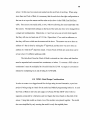
INTRODUCTION
1.1 Objective
This research is to take the initial steps to finding the viability of a two finger controlled
method of controlling functional electrical stimulation walking of partially paralyzed
patients. First, the JACK 5.1 human modeling software by UGS Corp., was used to
attempt to control a virtual human model by controlling the position of the ankles on the
virtual human. Another human model created with VRML language was then tested
using the Flock of Birds motion capturing system and Matlab programming software to
try to control the model's walking using just two sensors. Before the software and the
interfaces are covered, more must be known about spinal cord injuries, and functional
electrical stimulation, to see where it has worked, and it must be ascertained how
effectively legs do respond to it.
1.2 Spinal Cord Injuries
1.2.1 Anatomical Consequences of Spinal Cord Injuries
The spinal cord is a large bundle of nerve fibers that carries the signals from the brain to
the rest of the body via the spinal nerves to help control body movement, sensation,
reflexes, and autonomic functions. Surrounding the spinal cord are vertebrae that protect
the spinal cord, as well as provide openings for spinal nerves to enter and leave from the
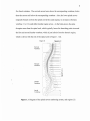
spinal cord. The cervical region is made up of seven vertebrae, the thoracic region has
twelve vertebrae, the lumbar region has five vertebrae, and the sacral region made up of
1
2
five fused vertebrae. The cervical nerves leave above the corresponding vertebrae; below
there the nerves exit below the corresponding vertebrae. Also, the lower spinal nerves
originally branch out from the spinal cord at the cauda equina, so an injury at thoracic
vertebrae 11 or 12 could affect lumbar region nerves. As the body grows, the spine
elongates more than the spinal cord, which typically leaves the branching point at around
the first and second lumbar vertebrae, which is just inferior from the thoracic region,
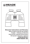
which is shown with the rest of the spinal cord in Figure 1.1 [1].
Figurt~
Ccrvk,tl
VcrtebnH!
C
)
\
TlHU" I.ciC
\ 'cl'te hnll~
0'
I.llmbar
\ 'crtebntc
Silentl
Vertchrac
Figure 1.1 Diagram of the spinal nerves numbering system, and regions [1]
3
~ )),":11_1',. ,I 't"., (,,,)!.-V 1 .,. <f(·!It·.)I<},j~<·~
.. I",.."
I:.'~ l:l~1"' f ' 't·~I" 1'1, p·,'1t
J ... nl\).t
"Jt
...
( \ f ......
Iv.t.'( ",,
~
( !
,"·fAiok· ~H( :tl'~
4\H >.hq. ("",
tt~'lnld',
'1),:-,
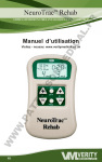
Figure 1.2 Dermatome map [2]
The severity of the spinal cord injury depends on the location of the where there is
a loss of sensation or movement; the more the injury is more anterior, the more sensation
that is lost. The dermatome map in Figure 1.2 above shows what spinal cord injury level
affects what region ofthe body and below. Tetraplegia occurs when the injury occurs
from damage to the first cervical nerve to the first thoracic nerve. Patients with injury of
the 4th cervical nerve and above typically require a ventilator to breathe. Paraplegia
occurs from damage in the second thoracic nerve to the fifth sacral nerve. Tetraplegia
can result in loss of movement and sensation in the neck, head, upper chest, shoulder and
arms and below, while paraplegia results in loss of motor and sensory functioning in the
middle of the chest, stomach, hips and legs. When there is some form of trauma to the
4
vertebral column, the vertebrae can fracture or displace the vertebrae from the column
causing severe pinching on the spinal cord causing internal bleeding and swelling. A
more severe injury could completely sever the spinal cord, completely blocking any
transmission of information past the point of injury. Another result of the injury is the
unabated action of spinal reflexes, which causes increased spasms, tone, and spasticity.
Injuries in the cauda equina and the conus medullaris result in different outcomes than the
rest of the spinal cord. The conus medullaris is at the base of the spinal cord where it
visibly tapers, and where the spinal cord branches out is the cauda equina. In these two
lower regions of the spinal cord injuries block the signals from reaching the actual spinal
cord, and as a result flaccid paralysis occurs, which means that there is no muscle tone
due to reflexes that are unable to proceed. Above these two regions spastic paralysis
takes place due to the tone due to the reflexes [1].
Doctors rate the level of injury based upon the lowest level of feeling and
movement on both sides of the body, which may be injured to different extents. A motor
score is determined from 0-5 using 10 myotomes or index muscles. 28 dermatomes, or
sensory points are also tested on the skin to determine the level of sensory loss. The
extent of injury helps doctors figure out what course of treatment is needed. Typically a
major area checked is the anal area, which evaluates if the anal sphincter is able to
contract normally to allow for bowel control and sensation. This is rated on the ASIA
Impairment scale where A is a complete loss of motor and sensory in S4 and S5, and E is
normal motor and sensory functioning [1].
5
1.2.2
Incidence of Spinal Cord Injuries
Spinal cord injuries can occur for many reasons, and are typically due to sports related
injuries, or car accidents. In the United States there are approximately 12,000 new cases
each year, and a recent estimation in 2007 brought the total number of people with spinal
cord injuries in the U.S. to approximately 255,702 cases. Spinal cord injuries affect
many young adults, with the average age being 39.5 years, which has steadily increased
due to the rising median age of the population. Males also make up approximately 77.8%
of spinal cord injuries [3].
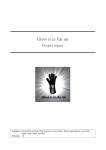
As shown in Figure 1.3 below, vehicle motor crashes make up 42% of all cases,
falls account for 27.1 %, violence for 15.3%, and sports injuries make up 7.4%. It is
interesting to note that gunshot wounds account for the majority of violence related cases,
and the percentage of sports related cases has decreased, while the percentage related to
falls has increased over time while the percentage for falls has increased [3].
Etiology of SCI Since 2005
Sports
7.4%
OUlerl
Unknown
8.1%
Vehic.
Crashes
42.0%
Violence
15.3%
Figure 1.3 Pie diagram of the major causes of SCI [3]
6
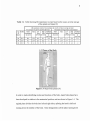
Table 1.1 Table showing life expectancy in years based on the cause, severity and age
of the spinal cord injury [3]
Ufi: i:~I.l;c tllllcr ( ~ellr~) rur IJu"t-l nj ur~ b~' sl'n-ril~' uf inj uQ IntI lI.\/e lit illj ur~
f ur I'cr~t)(I" whll~uP'i\'C the nnt 24 huun
fl)qtL'f'lI'JIIHun hinl: IIIIL'1IJOI I ~e3rpu~l·i!l.iu n'
III
FU llcti UlIlll lil.
Luw
'reIn
Jnju ~'
A(f~ LI.' \'L'I
(C5~C8)
A¥L~
:\uSCI
;\lo!ur
f'llrll
Hi~h
~ltJlf)r
h'l1tillitor
('lirll I> L111.11(1.1.'111 FUULtiuUllllit
(C I.(:'4)
III
A(f~Lc\:d
Ijllrll
Am' Lcn~
Ltn\
\ 'l'tltihtltJr
Hi~h
reIn
lelrll Ul'Pl'ft dcn.t
«(:5·(:8) (Cl-(:4)
lit
"\11\1...,\.1:1
~\A
52 ,)(
45.1>
40 ,{,
j6. :
16.6
;:U
4fi ,,~.,
~ L'
4!J
39.5
' t ~
.)+,,)
2iUl
21.8
20,2
i .!
KS
2S ,{,
"'.,.
'" ..
bl}
Zt2
1',9
lj, t
HU
7.9
!A
!
l3.5
i
21)
..,,
"
.X
37,<)
:.:U
2u \
ILl
~,!I
j, !
1.3
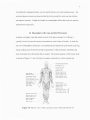
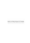
Figure 1.4 Major body planes [4]
In order to make identifying motion and locations ofthe body, major body planes have
been developed in relation to the anatomical position, and are shown in Figure 1.4, The
sagittal plane divides the body into left and right sides, splitting the head in half and
running down the midline of the body. Some designations call the plane running down
7
the midline the midsagittal plane, and any parallel planes are called sagittal planes. The
horizonal plane or transverse plane divides the body around the waist area into inferior
and superior sections. Finally the frontal or coronal plane divides the body into anterior
and posterior sections [4].
1.4 Musculature of the Legs and their Movements
In spinal cord injury cases the muscle system of the legs necessary for walking is
typically in tact, however the neural connections to control them is broken. In order for
any sort of stimulation of muscles to be performed, the function of each muscle in the leg
during walking must be known so that the placement of the electrodes contributes and
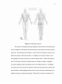
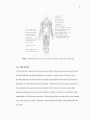
does not detract from the motion that is wanted. The muscle anatomy of the human body
is shown in Figures 1.5 and 1.6 below in anterior and posterior views respectively.
Figure 1.5 Anterior view of the muscular system of the human body [5]
8
Figure 1.6 Posterior view of the muscular system of the human body [6]
1.4.1 Hip Motion
The hip joints are ball-in-socket type synovial joints, where the spherical femoral head
resides inside the cup-like acetabulum of the pelvis. Each motion of the hip joint is
typically defined as motion in only one plane and affected by the muscles connected to
the pelvis, as well as the muscles of the thigh. Within the transverse plane, abduction is
the movement of a leg away from the midline of the body in a lateral motion, while
adduction brings the leg closer to the midline of a body. Another set of motions in the
sagittal plane is flexion and extension. Flexion brings the knees up such as when raising
a leg when going on a step. Extension of the hip moves the legs to be parallel with the
torso [7].
9
The major muscles involved in hip movements [7]:
Flexion iliopsoas, tensor fasciae latae, rectus femoris, sartorius, adductor longus,
-
adductor brevis, and pectinius
Extension gluteus maximus, semitendinosus, semimembranosus, biceps femoris, and
-
adductor magnus
Abduction Gluteus maximus, gluteus medius, gluteus minimus, and tensor fasciae
-
latae, obturator internus, gemellus superior, gemellis inferior, and pirifomis
Adduction adductor magnus, adductor longus, adductor brevis, pectineus, and gracilis
-
1.4.2 Knee Motion
The knee is primarily a hinge joint, allowing for the motion in the sagittal plane, and
additionally allowing for some slight rotating motions. The knee is a synovial joint at the
junction of the femur, patella, tibia and fibula. Soft and load absorbing cartilage known
as the meniscus, separates the femur and tibia. Besides providing cushioning, it
distributes the body weight between the moving bones at the joint. The motion of the
knee also utilizes some of the same muscles of the thigh as the hip to perform flexion,
which moves the foot towards the posterior of the pelvis, and extension, which brings the
knee to be parallel with the thigh [7].
Muscles associated with knee flexion and extension [7]:
Flexion Biceps femoris, semimembranosus, semitendinosus, gracilis, gastrocnemius,
-
plantaris, and popliteus,
10
Extension quadriceps (rectus femoris, vastus lateralis, vastus intermedialis, and vastus
-
medialis)
1.4.3 Ankle and Foot Motion
The ankle is made up of mainly the fibula, tibia and the talus, which is a tarsal bone. It
provides primarily a hinge-like motion, allowing for walking and pushing off the ground
to occur. Dorsiflexion moves the foot and toes upward towards the leg, decreasing the
angle between the foot and the lower leg. Plantar flexion increases the angle of the foot
relative to the lower leg and points the toes away from the torso [7].
Muscles involved in the motion of the ankle [7]:
Dorsiflexion extensor digitorum longus, extensor hallicus longus, tibialis anterior, and
-
fibularis tertius
Plantar flexion gastrocnemius, plantaris, soleus, flexor digitorum longus, flexor
-
hallucis longus, tibialis posterior, fibularis brevis, and fibularis longus
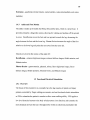
1.5 Functional Electrical Stimulation
1.5.1 Overview
The future of this research is to eventually have the leg muscles of spinal cord injury
patients controlled by finger walking movements, and use functional electric stimulation
or FES to stimulate the patient's muscles to allow some walking ability. FES applies a
low level electrical current to the body to help restore a lost function, and currently the
most abundant devices that use it throughout the world are electronic pacemakers that
11
help those with heart rhythm problems. Since it is not currently possible to simply
reconnect the spinal cord to restore functioning, other methods like FES must be tried to
offer an alternative method to fix to the problem of paralysis. Incompletely injured
subjects show improvement in their voluntary muscle control when the system is turned
off, while a complete spinal cord injury would not show any benefits when the FES unit
is turned off. Even though it is not a viable option for every patient with paralysis, FES
holds the promise to be very helpful to restore various body functions besides walking
and stability, which is one that is very complicated to replicate [8].
FES was first developed by W.T. Liberson in 1961 to help stop foot drop in the
swing phase of gait on patients with hemiplegia, or paralysis of the left or right side of the
body [8]. Muscles affected from a spinal cord injury are still healthy, but they however
do not receive any instructive signals coming from the brain to function resulting in
muscle atrophy soon after injury. FES uses electrical impulses to activate the motor
neurons that lead to the muscles to contract. If peripheral nerves get damaged,
denervation typically occurs, which requires a direct stimulation of the muscle is which
has shown to produce muscle fatigue and weakened pre-fatigued muscle activity [8].
Electrodes
0 0
Controller
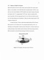
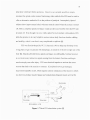
Figure 1.7 Basic FES stimulation system [8]
12
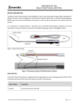
1.5.2 Electrode Technology
A sample stimulation unit as seen in Figure 1.7 shows electrodes, a stimulator and
sensors that bring about the electrical stimulation. The stimulator controls the level of
strength and the timing needed to help control a certain action by applying a sufficient
voltage to trigger an action potential in the muscles. Different types of electrodes can be
used, such as surface electrodes or implanted electrodes. Surface electrodes are typically
detachable and are used with a conductive gel to help transfer the signal through the skin;
some are also designed to be reusable. Applying these electrodes can be a hassle to
patients due to the time needed to reapply the electrodes. These electrodes also must
send the signal through skin and fat, and thus are less likely to precisely affect only a
certain muscle, but affect a group of muscles that can lead to undesirable contractions and
movement [8].
Implanted electrodes are placed inside the body during surgery and allow for
greater selectivity as to where the stimulation is applied. Various types of implanted
electrodes have been created including intramuscular electrodes (fine wire placed into the
muscle), epimysial electrodes (foils placed on the muscle surface), nerve electrodes
(rubber and metal cuffs surrounding nerves), and flat interface nerve electrodes (contact
arrays surrounding nerves). Leads are insulated wires that send the signals from the
stimulators, which are typically external, with the leads passing through the skin, or
implanted into the body. External stimulators can also use radio signals to transfer the
signal through the skin [8].
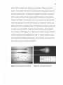
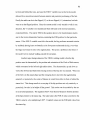
Intramuscular electrodes (Figure 1.8) are pressed into the belly of the muscle, and
held in place with an anchor, that still allows for its removal. A similar design can be
13
used for EMG recording to allow feedback from stimulation. Epimysial electrodes
(Figure 1.9) are sutured to the exterior ofthe muscle surface using surgical sutures near
the neuromuscular junction. The leads are also designed to be flexible to not interfere
with movement, and the electrode is small enough for implantation in the extremities.
The nerve cuff (Figure 1.10) is an array of one or more contacts in an elastic sheet that
wraps itself around the nerve several times allowing it to automatically conform to the
diameter of the nerve it is implanted around. This electrode also requires no sutures and
can easily be removed if needed. Another nerve-based electrode is the Flat Interface
Nerve Electrode or FINE (Figure 1.11). This electrode is made of an array of electrical
contacts to be placed around a peripheral nerve trunk. It is able to stimulate as well as
record to help provide feedback simultaneously. This array allows more contacts to be
placed on the nerve than using other methods [9].
Figure 1.8 Intramuscular electrode [9]
Figure 1.9 Epimysial electrode [9]
14
Figure 1.10 Spiral nerve cuff electrode[9] Figure 1.11 Flat Interface Nerve Electrode[9]
Besides stimulating the muscles, it is useful to also obtain information back from
the body to allow for on the fly adjustment of the FES signal. Proprioception is the
ability of the body to know what position it is in, and this important sensory information
is often lost during many spinal cord injuries. Artificial sensors can detect the current
angular position of a limb, or allow for a pressure sensor to signal when a walking
movement is completed. The feedback can directly feed into the system to adjust its
stimulation, or give the feedback to the user to adjust their motions [9].
1.5.3 Major FES Walking Studies
In 1994 researchers from Cleveland, Ohio began to use implanted electrodes in order to
try to create normal walking movements for SCI patients with injuries ranging from T4 to
T12. They utilized a selection of electrodes, including percutaneous intramuscular,
subfascial implanted electrodes, and surface electrodes to supplement the trunk and thigh
muscles. Their system allowed the use of a large laboratory computer or a portable
system that each was able to support up to 48 different stimuli. Stimulation patterns were
15
taken from electromyograms of normal activity, but the pulse width of the stimuli was
tailored for each individual patient by manually testing to see the value where the
adjacent muscles weren't activated. The maximum pulse width was 150 microseconds
for direct muscle stimulation, due to it being a safe value. Some muscles required
multiple electrodes due to their size, and typically asymmetrical gaits attained due to
varying levels of muscle activation on each side due to imprecise positioning of
electrodes. Also, stimulating unwanted muscles had to be avoided in the legs such as the
tibialis posterior muscle because it would invert the foot, or position the sole to face
medially. Patient's ankles were immobilized to help stop foot inversion, but to stop the
problem both from the source and physically was the best option to halt the complication
in gait. The patient's own observations, as well as the programmers view were used to
help modify the asymmetry by slightly altering the pattern, which also helped to make the
walking require less effort from the patient. It took between 100 and 300 milliseconds to
reach 90% maximum torque, so they found that this delay must be taken into account.
Another important time frame measured was relaxation time, which were longer under
muscle fatigue, since they viewed the timing critical to the proper stimulation under
fatigue conditions which always occurred during tests. They concluded that the energy
expended by paraplegics using their system was still too high based on their results. The
aerobic capacity for a paraplegic is 36 m1O2/kg/min, and averaged 28 m1O2/kg/min to
average a walking speed of 0.5 m/s. Since walking requires only 8 mlO2/kg/min by
healthy adults, researchers concluded that there is still more research needed to allow
greater distances [10].
One specific research group headed by Daniel Graupe, has tried to reach similar
16
goals by using FES stimulation for short distance walking using a more user friendly
system [11]. Their Parastep system uses non-invasive surface electrodes controlled by
buttons (Figure 1.12) housed on the patient's walker (Figure 1.13), connected to a small
portable computer attached to the patient's belt as shown in the Figure 1.14 below.
Figure 1.12 Walker mounted control buttons [12]
Figure 1.13 Patient using Parastep system [11]
17
Figure 1.14 Waist mounted Parapack, used to carry stimulator and battery pack [12]
The system is manufactured by Sigmedics Inc. of Northfield IL, and was approved by the
FDA as a Class III medical device in 1994, making it the first such FES ambulation
system approved and tested on over 400 thoracic level paraplegics. It only requires eight
AA batteries to power the system and requires the user to hit buttons on the walker to
trigger different walking movements. Although the legs carry approximately 95% of the
body weight of the patient, the walker provides help for balance, as well as act as a safety
backup to prevent falls and possibly more injuries. Twelve replaceable electrodes (6 per
side), are used and placed over quadriceps muscles, the common peronal nerve, the
paraspinals or gluteus maximus. The common peronal nerve and the gluteus maximus
electrodes are sometimes not necessary for some T9-T 12 patients [11]. The surface
18
electrode placements are shown below in Figure 1.15.
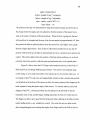
Figure 1.15 a) Patient outfitted with surface electrodes b) locations of lower leg surface
electrode placement c) locations of lower back electrode placement [11]
The signals produced by the 9.2 oz Parastep stimulator, utilize trains of signals to
imitate the natural peripheral nerve stimulation in healthy adults, and are varied based on
the movement required. Users press buttons housed on the handlebars of a walker to
choose what train of signals is needed, as well as the ability to increase and decrease the
stimulation voltage to allow for greater muscle recruitment and more forceful movement
by the surface electrodes. The train durations are 150 microseconds, spaced 42.0
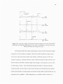
milliseconds apart, with a maximal average stimulation of 0.54 V. Figure 1.16 shows the
envelope voltages used for a sequence of movements for a patient standing up out of a
chair, taking a right step, taking a left step, and finally sitting down. Notice that in
standing up and sitting down, a higher voltage is required due to the increased forces
required to stabilize the body at the unstable position of being partially standing [11].
19
Figure 1.16 Envelope voltage for Parastep electrode stimulation for the right and left
quadriceps, and right and left personal over a cycle of standing up, taking a right step,
taking a left step, and sitting down [11]
The Parastep study also required participants to meet certain criteria that include
being six to twelve months post surgery, stable ortho-neuro-metabolic systems, intact
lower motor units, good bone health, trunk stability, sufficient response to FES, low
amount of spasticity, sufficient balance control, sufficient hand and finger control to use
button controls, and finally adequate upper body strength to lift themselves up for a few
seconds using a walker. Tests showed that the physical effort to stand up using the
Parastep system was more than six times more strenuous for SCI patients than unaided
healthy adults based on oxygen uptake showed that strong cardiovascular health was very
important to be a candidate. After undergoing over a months worth of sessions in a
20
controlled testing environment some were allowed to use the device in their home [11].
The very promising results of this study show that after the training nearly all
patients were able to walk 20-30 feet in one trial, and a dozen were able to walk over half
a mile with the Parastep system. Unfortunately this device does not seem to allow
continuous ambulation of its patients, allowing for short walking movements out of their
wheelchairs. At the end of the study there were many positive health improvements
including decreased resting heart rate, a 10%-22% increase in thigh muscle mass, very
low prevalence of bed sores, all had a lessoning of spasticity, and finally it had helped
decrease depression due to their lack of mobility. These results show how FES
stimulation and ambulation of paraplegics is valuable to not only provide some mobility,
but help the overall health of the patients due to their inactive lower body due to constant
sitting in a wheelchair. The small number of electrodes allows for the patient to
independently apply them in a short period of time [11].
The Parastep system is still currently available from Sigmedics Inc, and is used by
patients. More electrodes have not been added to the system, because it was observed
that with more than 6 stimulation channels, the patients soon stopped using the system.
The consideration of the ease of donning is very important to FES systems if it is too
difficult or time consuming [13].
The above study of the Parastep showed how fatigue is a major concern when
using FES by limiting patients to only ambulate for a limited distance compared to
healthy adults, therefore showing that effecting long-term muscle stimulation has still not
been achieved. Fatigue can generally be defined as a reduction in resulting muscle force
due to neuromuscular propagation, excitation-contraction coupling, or metabolic changes.
21
In order to study the muscle fatigue from use of FES, the M-wave (the sum of all muscle
fiber action potentials) are measured. With respect to the metabolism in muscle fibers, as
more ATP (adeonosine triphosphate) is used up by the muscles, less myosin heads are
able to attach and bridge to the actin filaments than before, producing a smaller muscle
force. While not studying leg muscles but arm muscles, they have helped characterize
and measure an important factor in FES research. M-waves were measured on tetraplegic
subjects after 5 minutes of isometric exertion, and showed a significant decrease in force
by about 50% [14].
A more recent study tested the effect of varying the frequency of stimulation on
the muscle force from the quadriceps muscles. More fatigue resistant motor units aren't
always recruited during FES that can normally help fight fatigue in healthy legs. Larger
motor neurons generate more fatigue than smaller ones. Researchers found that forceintensity curves normalized to the peak force at the longest duration pulse were
exponential and did not vary due to stimulation frequency or due to fatigue. While laying
the groundwork for future research, it shows that adjusting the stimulation frequency
does not help reduce muscle fatigue due to FES, and other methods are needed to
increase the distances walked [15].
The current FES systems show great promise and advancement to hopefully allow
better controlled walking for SCI patients. Most likely a walker or brace will be needed
in conjunction to help the reduction of the amount of FES and reduce fatigue. Better
understanding of muscle stimulation is necessary to know where to apply electrodes to
the patients to better reduce fatigue [8].
22
1.6 Finger Walking
Current functional electrical stimulation controls consist of ring mounted buttons [16] or
walker mounted system [11] rely on set commands that can vary stimulation magnitude,
but does not give the user an intuitive way of inputting where they would like to go.
There are many complex obstacles encountered throughout daily life such as steps, curbs,
potholes, children's toys, and therefore it would be very difficult to navigate these with
previously set step distances. It was first proposed by Matthew Noesner in 2004, that
using fingers to mimic the walking motion could help provide the input for FES induced
ambulation. It is a motion most people have tried at one time on a table and can one can
easily duplicate. Flocks of Birds sensors (Ascension Technology Corp.) were attached to
the index and pointer fingers, and the fingers were "walked" over a small force plate.
The position data was recorded for two subjects and compared to actual gait data to see if
they correlated well. Using a walking speed of approximately 1.5 m/s the measured foot
position data was shown to be very similar to actual gait data. The normalized ground
reaction forces were also very similar showing scientifically that using the fingers to
produce a walking motion mimics normal ambulation, so that it can be an option for an
FES controlling system [17].
1.7
Human Gait
In order to model human walking the current human gait must be used as a template for
the movement. Human gait during walking has been extensively studied for many years
using motion-tracking techniques that typically utilize cameras and using either active or
passive markers placed on repeatable anatomical positions. Active markers either are
23
made up of different lights that light up in sequence very fast, or emit a magnetic field
that can be received by a transmitter. The cameras also find passive markers optically
find reflective markers and the positions are recorded by the software [18].
In order to help as a goal for injured patients during physical therapy, scientists
have characterized normal gait, providing a basis to which to compare abnormal gait.
Gait is characterized by two main stages that are repeated cyclically during walking for
each leg, the stance and swing phases as shown below in Figure l.17.
Figure 1.17 Human walking gait cycle [19]
During the stance phase, the heel of the foot makes its initial contact with the
ground, absorbs the energy from the body's downward momentum during loading as the
foot flattens out on the ground, and after the hips swing over the foot in stance the heel
loses contact with the ground, and finally the foot is pushed off by primarily using the
gastrocnemius muscle to provide a toe off event. During a brief moment during walking
24
called the double support phase, both legs are in stance phase as one is preparing for toe
off and one has just completed heel strike. In the very middle of the stance phase is also
a point where the swinging foot passes by the stance foot and the center of mass is at its
highest point during the gait cycle, this is called the mid-stance event. Right after a leg
performs toe off that leg is then in the swing phase where the quadriceps muscles are
lifting the leg up over the ground as it is moved ahead of the other foot. Swing phase
then ends once it touches the ground, and performs a heel strike. This cycle continues as
a person is walking. The relative time of the stance and swing phases if abnormal can be
indicative of a disease or injury. Typically the stance phase of one foot takes up 62% of
the total gait cycle time, and the swing phase takes up the remaining 38%. If a patient
has a painful limb, such as from avascular necrosis (bone death due to loss of blood
supply to the bone [20] it will alter the phase times, by lengthening the amount of time
the non-painful limb is in stance phase, and shortening the amount of time the painful
limb is in stance phase. If a person walks fast enough, they will reach a point where they
will start experiencing flight when neither foot is in the stance phase and then has
changed from a walking gait to a running gait. A running gait is not currently a priority
for an outcome for FES or physical therapy for those with spinal cord injuries where
walking gait is the ultimate goal [21].
As was discussed in the FES section, current FES systems do not allow for
unassisted walking, which would have an impact on the natural gait of the patient such as
if they lean their weight forward onto a walker. The healthy human gait very effectively
uses the body's momentum to continue the gait cycle, and the abnormal movements, or
slow speeds from FES walking certainly would have a negative effect on the observed
25
motion. Future research of FES systems could help lead to a more efficient and
unassisted walking gait which would help reduce the big problem of fatigue in FES
patients.
1.7.1 Winter's Gait Studies
A seminal set of gait data was produced by David A. Winter using a camera system,
along with the use of the link segment model. This model divided the leg into segments
where the mass was only acts on the segment at the center of mass. Other rules of the
model are that all the joints are hinge or ball and socket joints, as well as the following
are kept constant, the location of each segments center of mass, the moment of inertia
around the center of mass, as well as the length of each segment. The link segment
model shown below in Figure 1.18, greatly simplifies free body diagram study of the
forces acting on each joint and segment including the gravitational force, ground reaction
force, as well as muscle forces. Winter also was able to use the segment locations
captured plus the subjects height and weight to determine the moments at the hip, knee,
and ankle, plus potential and kinetic energies at each segment. He used the
anthropometric studies by Drillis and Contini in 1966, which could produce the
approximate segment lengths to use in the link segment model. Approximate segment
weights, center of masses, density, and radius of gyration were determined from research
by Dempster from 1971 to 1973. The position data calculated from the finger model will
be compared to Winters position data of the hip, knee, and ankle to see how well the
finger walking model can provide angle and position data to drive the FES stimulation
[18].
Figure 1.18 Winter's Link-Segment Model [18]
1.7.2 Energy Storing Foot Prosthesis
The problem that current FES technology produces limiting fatigue makes it necessary to
have the walking as energy efficient as possible. Since the 1970s energy-storing
prosthetic feet have done just that, and allow amputees have a foot design that gives them
much of the function of a real foot. These prostheses store the energy from walking in a
curved leaf spring in order to release the energy to help with toe off during gait. A
similar design could be utilized in conjunction with FES, to allow the foot to lift off the
ground easier during toe off utilizing the energy it stored while the spring compressed in
the stance phase as the angle of the leg and foot decreases. The device would go around
the existing foot, contain a leaf spring, and attach firmly to the lower leg and ankle like
an ankle foot orthosis (AFO) typically used for foot drop, which causes the foot to drag
27
on the ground due to deficient dorsiflexion. One such device is the Otto Bock 28U11
energy return AFO shown below in Figure 1.19. It is made out of carbon fiber making it
lightweight and small enough to fit in patient's shoes. It utilizes a strap on the lower leg,
and is able to help dorsiflex the foot. These devices would also need to help with ankle
stability that is necessary to control detrimental foot movement due to FES stimulation of
the lower leg muscles, or work in conjunction with another ankle brace [22].
Figure 1.19 Otto Bock Walk On 28U11 [22]
28
1. 7.3 Gait Harness
Most FES systems utilize a walker for support, which is fairly portable and lightweight.
Another option that could be used clinically with a finger walking system could be a gait
harness that is able to fully support a patient if they fall. Walker systems rely on the
users upper body for support, and require the patient to lean forward. They also need to
push the walker forward in a coordinated fashion. Harnesses have proven to be very
useful in gait studies on treadmills, allowing the person to practice walking in a
controlled environment with no risk of further injury by falling, and allowing fewer
therapists to assist during trials and set up. The Complete Gait Harness system (model
GHS9000) by Second Step, Inc. provides a mobile harness system that allows for patients
to be supported while allowing them to travel around a room and rotate in 360 degrees. It
utilizes four castors that could provide motion in all directions once finger walking
control is fully developed in all directions.
Figure 1.20 Complete Gait Harness System by Second Step Inc [23]
29
This system shown above in Figure 1.20, could allow for a hand to be free to provide
control for the FES system with finger walking that a walker system cannot provide. It
also could reduce the high physiological load on the patients to reduce the energy needed
by balancing themselves on the walkers. In future research it could provide trials in a
laboratory environment, and possibly for use outside if the motion capture and computing
systems are miniaturized, and could be attached to the frame of the gait harness [23].
1.8 JACK Software
1.8.1 Overview
JACK software by UGS, is a comprehensive human modeling program developed at the
University of Pennsylvania, which also allows for adding environments in which to place
the models. The model humans are created using the heights and weight data from a 1998
US army survey for both men and women, and can be scaled and modified depending on
the size of the person desired. Human models and objects are able to be moved either
graphically with menus and mouse clicks or by using Python or Tcl programming
languages which are accessible in the software by opening up their respective consoles.
The software has mostly been used for ergonomics studies for refining workplace tasks
and setups. Workplaces can be populated with some provided models of common objects
such as chairs, tables, and a few sample machines, but also allow for users to create their
own objects created in CAD programs to be placed in the environment to interact with
the model. Since the model is designed using actual data for size and weight, the model
can give very valuable information that would normally be more expensive to test using
30
trials or studies with actual subjects. The models besides being the right size and weight
also have fully articulating joints, hands, coupled shoulders and clavicle joints and are
restricted to normal joint limits [24].
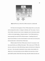
JACK utilizes a hierarchy system, as shown below in Figure 1.21 below where
the highest level is the environment (stored as .env files), which contains all the different
figures, positions, and constraints. Figures (saved as .fig files) are made up of at least one
segment and have information about their color, joints, and associated sites. Segments
(saved as .pss files) are made up of tessellated geometry that is used to make up an
object, and sites are specific positions in the coordinate system of the segment [25].
Figure 1.21 JACK modeling hierarchy [25]
1.8.2 JACK and American Sign Language
Previous work has been conducted at the New Jersey Institute of Technology Biomedical
Engineering department to help create a way of recording and translating American Sign
Language using JACK and Flock of Birds sensors. JACK currently does not provide
access to its inverse kinematics programming directly, so a workaround was created. A
31
cube is built into JACK that can be attached to a segment or node at one of its vertices,
and rules called constraints can be created which will allow a user to move the cube, and
the attached body part moves along with it as well. This has worked effectively by
placing cubes at all the fingertips, and multiple areas where American Sign Language
signs end up [26] [27].
1.8.3 Constraints
As previously mentioned, constraints are integral to allowing the model to move where it
is desired to using the attached cubes. Constraints also are already present in the human
models, which help provide rules for their manipulation and movement and ability to
stand. Before any user changes, there are constraints for the left toes, torso, right foot,
left foot, right toes, left knee limit, left knee rest angle, right knee limit, right knee rest
angle, left elbow limit, left palm, right palm, bottom head, left eyeball, right eyeball and
spine.
When creating constraints through the menu graphically, a large number of
options and points on the model can be defined. Constraints also can be created and
modified using the Jackscript command CreateConstraint.
Table 1.2 Table of possible constraint goals
Goal Type
Closest node
Face
Hold
Node
Relative transform
Goal Chosen
Picks the closest node on the closest segment
The closest point on the surface of an object is selected
The end effector is to remain at its current position when the
constraint was created
Picks a specific node
Picks a point in space that is relative a certain segment of the
figure
32
Site
Transform
Picks a goal that is a site
Specifies a point in space
Other Constraint Options:
Goal Site this is chosen to choose where the end effector is to be moved
-
End Effector Type selects what type of end effector is to be chosen from a node, the
-
closest node, or a site
End Effector this site, node or segment is chosen as the site on the model that is to
-
reach
Starting Joint the joint to be adjusted to keep constraint conditions
-
Rooting Constraint selected as the constraint where the body is anchored
-
Orientational Relationships
Aim the end effector is aimed at the goal, but does not need to be at the same
-
position, a new box opens to input the aim vector
Align direction the end effector and goal must aligned in the same direction,
-
and new boxes appear that allow the input of the end effector and goal vectors
Align frame the end effector orientation is attempted to be aligned with the
-
goal
Planar direction end effector and goal are attempted to be aligned in the same
-
planar direction by having the user define a vector for each, and tries to align
them
View the end effector attempts to be aimed at the aim vector, and disallows the
-
twisting along the aiming direction
None there is no orientation relationship
-
33
Positional Relationships
Limit spring pushes away from joint limits
-
Point to plane positions the end effector along a line
-
Point to point
Rest angle
None
—
—
—
positions end effector at the point of the goal
pulls toward a rest angle
there is no positional relationship
Positional/Orientation Weight, (POW Weight) a value from 0 1, 0 meaning fixed
-
-
orientation, and 1 weight is given to the position
Relative Constraint Weight a value is chosen to indicate the relative importance of the
-
constraint compared to other constraints
It is necessary to be able to accurately reproduce simulations in JACK, therefore
the programming language known as Jackscript is used, which is based on the language
Python. JACK allows the control of many options using the menus in the user interface,
and is more oriented to controlling much of the options through this. Most of the same
options can be modified using Jackscript, to allow fast changed of groups of options, or
movements at a time.
Besides constraints, another important set of the model properties are under the
graphical menu human control. Under here the user is able to modify models behavioral
constraints and to allow manipulation. The behavior menu allows access options for the
head, eyes, spine, torso, left hand and right hand, which all have a default setting as
release, while the left and right feet have a default setting of "hold relative to human".
Follow feet and step balance control, allow for the body to adjust its position when the
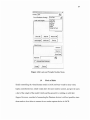
center of mass is moved through manipulation as seen in Figure 1.22. The goal of the
34
adjustments for the center of mass is to be centered over the feet. The necessary
behaviors options needed for creating walking motions are for the torso, feet and
sometimes spine, all shown in Figure 1.23 below. The torso can be changed to be "follow
feet", "release" or "hold current position". Torso control allows the spine to be kept
vertical and show how the body will adjust, either bend from the waist, curl from the
~
· ~I
Human: liack
UlijOihldldll
Human: fjack
Balance Control
Control TOIS.O
rl-;'-~~Iee-:----;: ,-~
I ('
r Type:
----'-'1
r.-
hold orientation
relea$e
I
, r hold c.urrent position
L _ _... _._..,,-.. ___.,______,_
t. ~ _~:~ v:.~~~~. " , __ ._,..._J
P"
r
I
Step Balance Control
Keep TorsoCentered
-_·_·_·_·_·--i
-(' input parameters I
r Bet1d Params: -·_·_·
Behavior Summary
Dismiss
I
Figure 1.22 Balance Control Menu
r.
bend from waist
I
from neck
t. .r,. . . . . curl
......_
. . . . . . . . . . . ...,.. _. . . . . . . . . . . . ---.. . . . . . . . . . J
Figure 1.23 Torso Control Menu
neck or other inputted parameters. The foot behaviors can also be changed as shown in
Figure 1.24 below. The feet are set to hold relative to human as default and can be
changed to hold relative to an object, hold relative to the world, follow the other foot, or
released.
35
H
Human: hack
.ControlFoot • right
c.'
r
hold reI. to human
r
hold reI. to obiect
(' release
r
hold reI. to world
Behavior Summary
follow left fool
Dismiss
I
Figure 1.24 Left foot behaviors
Once the behaviors are configured, the user is able to directly control the human model
by clicking on the manipulation picture, and choosing the desired segments to move.
Changes in the human control menu change the settings in the actual foot constraints
themselves. The default foot constraints are shown in Figure 1.25, showing that
jack.left_foot.distal site is the end effector, the starting joint is jack.left_hip, and the
default goal is hold. It is much easier to change options in the human control menus, than
modify multiple constraint properties manually.
36
Constraint Properties: jack.teffi7~ 0
C~straint:
f1J1
BiaCk.leiuoot
--~onstruction I Info r
Type of Goal:
hold
Sel Tf6t'lIJorm Locahon
End Effector Type:
site
End Efr. Site:
Iiack.lefUoot. distal
Starting Joint:
!iack.left.;.hip
r
Rooting Constraint
Orientational Relationship:
alignJrame
......J
Positional Relationship:
point_la_point
-J
I
I
orientatiOn< .......>Position Weight- - - - - - ]
u1 : 0
Relative Constraint Weight:
Priority:
(0.300m l
-1
11.0
CD
r
Use current orientation offset
r
Use current position offset
P' Active
Apply
Figure 1.25 Default constraints on the left foot
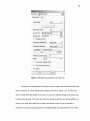
Another set of settings that is relevant is in the weights and measures module that
allows selection of a force distribution strategy as shown in Figure 1.26. It allows the
user to switch from the default of two feet, to one foot, walking, sitting, and sitting with
no feet on the ground. The menu also allows a change in gravity, and for the addition of
forces to the body that could help in future simulations where it may be needed to
account for a person carrying groceries or shopping bags, if long distance FES is viable.
37
Human: l:rack
Force Distribution Strategy:
ITwo Feet
.:---=- - - - -1
, Loads andWeights:- - - woFeet
Foot
oot
alking
Sitting
Sitting, No Feet
!I
I
I
' HideAfI
I Add Weight
Add load
1- - '
,
L_.~_·'
I
I
Remove All
I
J
Gravity
I
,""""",,,,,,,_.1
[ ShOW Forces,
I
I,
R~::e-]
Clear List
I
IAdd Joint: J' ,
Figure 1.26 Loads and Weights Module Menu
1.9
Flock of Birds
Ideally controlling the virtual human model in JACK software would be done with a
haptic controlled device, which would allow for more intuitive control, and give the users
a feel of the weight of the model's limbs and the ground it is walking on with their
fingers. However, a method of connecting the Phantom devices is still not possible, since
there needs to be a driver to connect it as a motion capture device in JACK.
38
The Flock of Birds sensors by Ascension Corp, however can provide a similar
control without providing a haptic response, and are already able to be read by the motion
capture software in JACK and are easily interfaced using Matlab and VRML 3D
modeling software. Most uses for Flock of Birds require many locations of the sensors
for it to successfully drive the model, and therefore it has been designed to handle
multiple sensors at the same time while preventing lost positions due to blocking
common with camera based tracking systems. Wireless sensors track the position using
one of three types of transmitters: short-range, mid-range and extended-range. The short
range only can transmit up to three feet, and can be mounted on articulating limbs such as
an arm to get it close to its sensors. The mid-range can provide up to a four foot range
and is good for desktop applications, and when there are conductive metal objects in the
vicinity of the sensors. Finally, the extended-range model has a range of 10 feet, and can
be used in conjunction with another transmitter to help create a 10 ft by 15 ft area for use.
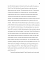
Flock of Birds sensors and transmitters are shown below in Figure 1.27. The signal used
by the transmitters uses pulsed DC magnetic technology that helps make the system five
times less susceptible to distortion due to nearby metal objects. Each transmitter can
track up to 4 sensors at a time and provide unrestricted 6 degree of freedom range of
motion by giving positional coordinates or angles, rotation matrices or quaternions [28].
A sample Flock of Birds setup diagram is shown below in Figure l.28.
Figure 1.27 Flock of Birds Equipment [4]
39
'-'~xt~nded '
1
!
Ex~ended "1
Range
Transmitter
Range
Transmitter
(1)
(2)
Figure 1.28 The set up of the Flock of Birds connected to a desktop [28]
JACK allows for the integration of Flock of Birds already built in as well as other
motion sensing devices such as a Cyberglove, Motionstar, and Vicon systems. Once the
Flock of Birds is selected, the type of sensor configuration must be determined, attached
to either a site, through mapping, or through constraints. Flock of Birds already has a
sensor map ready for use with JACK with eleven sensors. Controlling the feet will
require less and ideally rely on the inverse kinematics to resolve the rest of the body from
the feet position fed to it from the Flock of Birds sensor.
Different models of the Flock of Birds sensors exist and it was necessary to take
into account that they run at different clock speeds. Older versions run at 50 MHz while
the newer versions run at a faster 64Hz having an impact on the baud rate of reading from
the sensors. This clock speed is determined by using a simple command added to the
Matlab script. Since these hardware units have different clock speeds those with like
speed should be paired with each other when using a setup that contains more than once
40
sensor. In this case two sensors are needed one for each foot of each leg. When using
more than one Flock of Bird, it is necessary that the units be in the right configuration so
that one is set up as the master and the other as the slave via the FBB (Fast Bird Bus)
cable. One can use one serial cable, or two, with two allowing for more bandwidth with
the sensors. The dipswitch settings on the back of the units also have to be changed from
a single unit configuration. Dipswiches 1, 2 and 3 are set as up on both which signify
that they will run at a baud rate of 115 Kbs. Dipswiches 4-7 are used as addresses, so
that they will know which are the master and the slave. The master was set to have an
address of 1 that is done by raising the 7 th dipswitch, and the slave was set to have an
address of 2 with the 6 th dipswitch raised. If more Flock of Birds are used, these can be
set up to have 31 different addresses [28].
The data direct from the Flock of Birds is returned as a hex value, and therefore
must be unpacked and converted into centimeters or inches. To convert a FOB value to
centimeters it must be multiplied by 36 and divided by 32768. An angle is converted to
radians by multiplying by pi and dividing by 32768 [28].
1.10 VRML Model Design Considerations
In order to create a two-legged model for the legs using inverse kinematics, a previous
project is being using as a basis for the model and Matlab programming behind it. It used
the Flock of Birds to drive the arm angles of a Puma 560 like 6DOF robot with two
segments connected by a ball joint, and two fingers that close based on the pitch of the
sensor. Using that model as a basis, two of the models were placed together. The model
also was simplified by only moving the model in only the sagitttal plane.
41
The VRML model used was created so that a hip is the parent, and the two legs
are attached there and the hips are its children. The lower segments of the legs including
the thigh, knee, shank and ankle were also sequentially made children of each preceding
node. Each angle of the model had to be matched up with the same motion that the robot
arm made so that the legs moved like the robot arms. The hip position needed to be
mobile, so that the legs and hip are allowed to move from their place in the scene. In
order to dynamically determine the hip position, the pitch angle of the stance leg was
used with the length of the VRML leg, to find the vertical and horizontal position of the
hip that creates an arc-like movement when the pitch angle is varied. The knee and foot
angles also need to be in a natural range and be indicative of the actual position of the
fingers. It was also necessary for Matlab to know which leg was the stance leg, by
finding out when the foot was at the ground level, which determines on which foot to
base the hip position.
The inverse kinematics run used was from the Robotics Toolbox version 6 by
Peter Corke. This toolbox contains many useful functions that allow virtual robots to be
controlled. The ikine, and ikine 560 are two types of inverse kinematics available in the
Robotics Toolbox. Ikine returns the joint angles of a two-armed robot based on a 6 DOF
position. Ikine 560 also returns the joint angles of a two-armed robot, but does it more
efficiently using a symbolic method, and also can control a spherical wrist joint. Ikine
560 also allows for better customization of the direction the solution, when the function is
supplied a configuration matrix. This is needed because there can be many angle
solutions to a certain position of the wrist, and it is often necessary to have a certain
solution [29]. Further details about the VRML model are following in the results section.
42
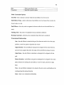
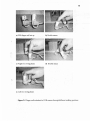
1.11 Finger Well Design
The setup of the sensors on the fingers needed to be repeatable, so that it is easy to take
off and on. Two small pieces of 1/2" PVC pipes were attached with string for each finger,
and the length was chosen based on how far each finger entered in order to put the
sensors at the same level when they are put on. After small 1/8" holes were drilled 1/4"
from the bottom of the pipes 180 degrees from each other, string was tightly tied to the
hole and the holes already on the bottom of the Flock of Birds sensors. This temporary
attachment was used which worked very well and allows little to no torsion and
movement. A small piece of Velcro was also used on the top of the sensor to allow for
greater friction so that there is no sliding between the sensor and the bottom of the pipe
and for a tighter fit. The model was set up for a right-handed person, and the model was
created to move from right to left on a table. The middle finger goes on the sensor that
feeds the master position, and the index finger feeds the slave sensor. The PVC pipe for
the middle finger was calculated to be 1.8 cm while the index finger needed a longer
length of pipe at 3.1 cm. It is also noted that this method can easily be replicated for
other users, the middle finger pipe length was the point on the finger where the pipe
stopped comfortably to the tip of the finger, and the index finger pipe length was the sum
of the middle finger pipe size plus the distance between where the pipes comfortably stop
on each finger. The Flock of Bird sensors are fairly large for something as small as
finger movements, and therefore movements are hampered slightly due to their size.
CHAPTER 2
RESULTS
2.1 JACK Modeling
Creating a walking motion by using constrained boxes using JACK software proved
much more difficult than anticipated. Since there are more constraints added to the
model, not all of them can be satisfied at the same time, and sometimes forces the model
to destabilize uncontrollably float away spin, or contort its limbs. When constrained
cubes were tested on the arms and articulated, the arms were able to resolve or reach their
desired location the cube was moved to. If the same technique is applied to the legs, the
model was very unstable after very small movements of the cubes, typically with the
torso and legs ending up in positions far away from the cube. In order to attempt to
correct this more constraints were added to try to keep it from floating away, however the
addition of more constraints did not abate the problem and the model remained unstable.
Using the human manipulation menu, it was possible to walk the model one foot at a
time, when the follow feet balance behavior was previously selected. The constrained
blocks used as a work around for the inverse kinematics were far less stable, most likely
due to the increased amount of simultaneous calculations performed by the inverse
kinematics and constraint functions. In order to help keep the model more stable, it was
attempted to add orientation constraints on the body relative to a floor set up on the XZ
plane where the models feet are placed, so that the waist could be constrained as if
connected on a sliding harness, that kept the waist at the same height but allowed the
model to walk forward or backward. The posture was also changed from the default
43
44
stand relaxed posture, to be standing with arms horizontally, in the stand_arm_span
posture so that the model could be more stable and balance better.
Directly creating constraints onto the feet did not allow for normal functioning of
the legs and balance. Instead of adding a constraint, cubes were created and moved to the
heels, but not attached. Then by changing the foot behavior from 'hold relative to world'
to 'hold relative to an object' to its corresponding cube, and then changing the balance to
"follow feet", the balance is allowed to work when the cubes are moved. In order to
verify that the balance was working, it was necessary to turn on the support polygon,
which shows a line from the ground to the center of mass site located on the lower torso.
If the model becomes unstable as if it were about to fall, the polygon on the ground and
the line normal to the ground turns from green to red. The model could then be fed
predetermined locations to the cubes by using the DoTogether, and MoveTo or Move and
drive the body to a walking motion and moving the torso with the feet.
45
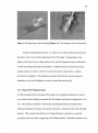
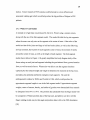
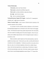
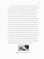
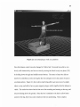
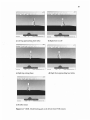
Figure 2.1 Jack attempting to walk on a platform
Once the balance control was also changed to 'follow feet', the model was able to very
slowly walk interactively one foot at a time by moving the block in only one plane (YZ)
by holding down the right and middle mouse buttons. The center of mass box did not
need to be controlled, as only moving the feet was enough to move the center of mass to
a normal position. Figure 2.1 above shows Jack being able to get up on top of a simple
object, a step, and able to have a green support polygon which signifies that the balance is
viable. The curled toes show that its feet are in fact touching and reacting to the step, and
not just floating above the ground. Since the box is attached to the heel to allow better
control of the leg, there was some variation in the toes positioning. More complex
46
motions were possible by holding down shift for each foot and being able to rotate the
box around the Y axis, and being able to continue walking as long as the feet allowed for
the support polygon to stay green. Sometimes the support polygon shows that the model
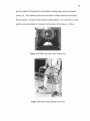
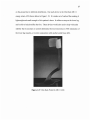
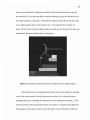
is in a stable position when it seems that it is not. The example below in Figure 2.2
shows JACK on the way down a flight of stairs, but with one foot forward of its body, the
model should fall down and thus show a red polygon.
Figure 2.2 Unbalanced position that shows as balanced in the support polygon
Upon further trials it was apparent that the body resolves the balance by checking
to see if the torsos position is directly between the two feet, or by using the boxes as
supporting the legs, even though they themselves are not supported by anything. JACK
software provides collision detection between two surfaces or segments and supplies the
body segments with weight. It does not treat the objects as solid when they collide, but
47
rather allows one to pass into the other. Since much of the software is based on
automatic movements and not real time, therefore it may not have been an important
feature, or too computationally taxing. Inverse kinematics can cause unnatural behavior
and positions during movement, only small steps were more successful in maintaining a
normal stance, since there is less of a chance of an unresolved movement, plus any
patient with spinal cord injury would only be making smaller steps, not a faster walking
gait like a healthy adult. These movements also were created by using mouse and menu
commands and unfortunately were not easily programmed using Jackscript and Python.
Only a few commands were referenced in Jackscript through the documentation, while
the remaining commands were unknown even by the software's technical support. JACK
software was not designed to allow for a real time walking simulation with balance
control. It does allow for a walking model, but only if numerous sensors were used all
over the whole body instead of two and not with inverse kinematics. This study did not
have the same results as previous research with attaching the blocks with constraints to
fingers and upper body parts, since moving the blocks which seemed to be much more
complex due to the balance control and resulting torso movements. While a good choice
for ergonomics and sign language simulation, it did not provide the control necessary to
allow a walking Jack model with two sensors to walk as was hypothesized.
2.2 VRML Walking Model
Once JACK was determined to not provide sufficient control and stability of a walking
model, the approach to finger walking method was switched to utilizing a VRML model
controlled by Flock of Birds sensors. The VRML model was created using V-Realm
48
Builder 2.0 software included in the Virtual Reality Matlab toolbox, and this creates 3D
models using a graphical technique, so one can instantly see how added objects and
translations changes the model. Model hierarchy is integral in VRML, allowing the
movement of a parent to move all of its children with it. Each segment in the legs on this
model, a distal object is the child of an object proximal from it as one goes down the leg
from the hips. The legs of the model were created with a spherical hip, cylindrical thigh,
spherical knee, and a cylindrical shank on each leg. The uppermost level of hierarchy of
the model is the hipinit hip, and each leg's hip is a child of that and 0.4 out laterally from
that. This master hip being separated from each leg's hips was done for aesthetical
purposes, plus since each leg is being restricted to only move in the sagittal plane, it is
not made more complex since the model would look the same from a lateral view. A
green cylinder was later added to connect the hips to help show how the hips are all
connected at their parent hipinit that was used to drive the hip movements of the whole
model. The ankles are made up of three identically sized spheres on top of one another,
so that each is responsible for only one type of rotation from the FOB sensors, either
pitch, yaw or roll with the hierarchy descending respectively. The foot was modeled as a
thin rectangular prism, as a child of the ankle roll sphere. Before being restricted to
anatomical movements, it was able to react to whichever orientation the FOB sensor is in.
The right leg was colored red so that it could be easily identified as the right leg even
when viewed directly from the left or right side. Other objects/nodes added to the model
are a floor that will show the position of the table that the FOB transmitter is placed, and
a torso, which was made to be simple, so that processing power could be used on
displaying the legs only, and could in the future be modeled as providing the mass of the
49
torso onto the legs. Viewpoint nodes were also added so that one can easily switch
between different views such as in front and to the side of the model. This was very
important while trying to identify and remove unnatural movement of the legs and hips.
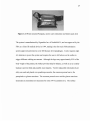
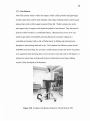
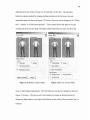
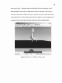
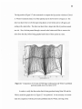
A front and side view of the model is shown below in Figures 2.3 and 2.4 respectively in
a position to prior to any input of location, which also shows both legs clearly.
Fite
View
Viewpoints
Navigation
Rendering Simulation Recording
Help
Figure 2.3 Side view of VRML walking model
50
File
View
lin Front
Viewpoints
Navigation Rendering Sunulatkm Recording Help
3 .., ,... , ~ I FII'
3 :;:d. ! ct
~
.::::------
I . I~
~.
III
Figure 2.4 Front view of VRML walking model
The basic design considerations were that the swing leg would be modeled as a
double pendulum starting at the hip and the knee and foot locations are given by the
inverse kinematics found in the robotics toolbox. Also, knee angle of the stance leg is
assumed to be zero or under knee extension, and the location of the ankle is used to
determine the hip position of both hips at the same time, which are modeled as being in
the same location. The hip location is determined by using a known leg length and the
angle of the shank in relation to the ground, and is like a single inverted pendulum. The
details of these considerations are
In order to try to mimic walking motions with the fingers and only two sensors,
inverse kinematics was necessary to produce the hip, knee and ankle angles. The puma
51
560-like VRML robot provided a great method of determining the leg angles, however it
had to be modified so that unnatural leg positions were avoided as much as possible. If
an FES system were controlled using the computations from a model with inadequate
positioning, the patient would form uncomfortable or even painful positions. One of the
most important changes was the controlling of the knee angle. The knee range of motion
due to bone, ligament and tendon boundaries, is such that once full extension of the leg is
reached, the knee does not rotate anymore, and when the knee is anterior to the torso and
flexed, the knee is bent so that the foot is below and the interior angle is pointed to the
ground. When the knee is flexed and posterior to the torso, the interior angle is pointed
toward the sky. These natural movements are controlled by the solution that the ikine560
inverse kinematics engine determines and must then be properly configured so that the
natural movement is created. The inverse kinematics only uses the FOB positions and
not orientation that is instead used to control the foot angles. Altering the configuration
vector in the Matlab code controlled the ikine outputs.
qM=ikine560(robotM,TRM,[ 1"u''f]);
The controls are based on the original robot orientation, which is inverted in the walking
model. The hip can be in the left-handed (T) or right-handed (`u'), and currently is in
the left-handed solution, which allows the robot to walk only from right to left as seen
when facing the front of the Flock of Birds transmitter with the cord exiting from the
other side. The knee joint can be in knee up (`u') or knee down (`d') orientation. This
setting is regulated so that when the foot position is posterior to the torso during the
swing phase it is in the elbow down position and once anterior to the torso it is in the
elbow up position. Switching of solutions make the knee angle correct when the foot is
52
in front and behind the torso, and once the FOB Y variable was not fed to the model,
allowed for a smooth movement between anterior and posterior positioning of the feet.
Finally the ankle can be in the flipped (T) or the not flipped (`u') orientation, but both
were set as the flipped position. Since the current model is only needed to walk in one
direction, the Y variable is not needed and when still used in the inverse kinematics,
created problems. The matrix TRM in the equation above is the transformation matrix
sent to the inverse kinematics function containing the FOB position for that particular
sensor. If the FOB Y variable were fed to the model, the hip performs unwanted rotation
by suddenly placing knee out laterally as the foot passes underneath the hip, even when
the finger movement is only in the sagittal plane. This poses a problem in the future if
the model were to include walking outside the one plane.
Another major design element of the VRML walking model is that the hip
position must be determined by the position and orientation of the Flock of Bird sensors,
which correspond to the left and right ankles alone. The characteristic up and down as
well as the forward and backward swaying motion of the hip also was desired. When one
of the feet is in the stance phase and the swing leg foot is moved in the sagittal plane
anteriorly or posteriorly, the center of balance is varied from either in front or behind the
stance foot. This change results in a swaying of the hip positions not only anteriorly or
posteriorly, but also in its height off the ground. This motion can be modeled by the use
of an inverted pendulum. The equations below were then developed to find the position
of the hips relative to the stance leg. The xadj value is the FOB X value converted to the
VRML value by a by multiplying 0.3877. Footpitch values are the FOB pitch value from
the stance leg.
53
angle= footpitch+pi/2;
deltax= (length of leg) * cos(angle);
deltay= (length of leg) * sin(angle);
hipx= -deltax - xadj*0.3877+1.5;
hipy= deltay - 1.9;
The position of the hip was determined by using the localized change in position due to
the change in the foot angle, and was adjusted so that the position of the stance foot is
used as the center of rotation of the hip positions. When the foot is going into the heel
strike position for example and the toes of the foot are angled up approximately 45° from
the ground, the hips are placed posterior from the stance foot, and slightly more caudal
than the original hip position. Once in the toe off position and the foot is near the 45°
position with the heel up, the hips are subsequently moved to a location more anterior and
caudal. This motion helps mimic the position of the hips during walking very well and
currently allows the model to walk forwards and backwards only in the sagittal plane.
Figure 2.5 below show the PVC finger wells attached to the top of the Flock of
Birds sensors in use though different gait positions. The sensors were attached using
cotton string, so to be easily removable, if the sensors have to be used for other uses. l.5
cm lengths of the PVC pipe were cut longitudinally in half, so that a semicircular portion
was attached on the bottom of the sensors to allow for easier rotation of the fingers on the
table, instead of using the square edges of the sensors. To increase traction, and avoid
slipping of the PVC, a texturized rubber mat was placed on the lab table so that the
transmitter rests on top, and the finger walking takes place in front of it on the mat too.
The fingers are able to get a good feel for the ground when walking on the table, provide
tactile feedback that is very valuable for control. The wells also act as a splint on the
distal interphalangeal joint, limiting the angles of the finger read by the FOB to only be
54
the equivalent knee and hip angles. This method does have its limitations in that the
sensor themselves are 1.7 cm in depth, creating a different point of rotation during toe off
compared to the model or an actual foot. The resulting lengths of the leg segments are
also uneven compared to actual leg lengths. The "shank" of the finger was measure to be
5cm, and the length from the proximal interphalangeal joint to the bottom of the sensor
was measured as 7cm. While not completely modeling a foot and its geometry, the
method allows the fingertips to accurately control the model, which is enough to drive the
model and move the hips along with the legs. This simplicity, allows it to be easily put
on and off, as well as modified for users with different sized fingers using liners to
decrease the inner diameter of the pipe so fingers do not slip out providing better control.
PVC pipe of different diameters can be also be attached using string as shown below, so
that the same sensors can be used with different people.
55
a}FOB.fi,p.ger well set up
b) Double stance
c) Right foot, swing phase
d) Double stance
e) Left foot swing phase
.
.
.
..
. Figure 2.5 Finger wells attached to FOB sensors through different walking positions
56
As can be seen below in images taken from the model running in Matlab 7 in Figure 2.6,
the model is able to replicate fairly well the major events through gait smoothly. The
foot angle was modified so that after the foot flattens on the ground it stays on the ground
until the foot lifts off. While not mimicking the typical motion of the foot, it has been
adjusted so that the model has an element of an energy storing prosthetic foot that could
help reduce muscle fatigue, and requires no power. The foot would store energy as the
torso moves forward while the foot is flat, so that once the other foot does heel strike and
less body weight is on the stance foot, the foot would release the energy and assist the
patient with toe off. Without the modification, the foot slightly goes through the surface
of the floor in the VRML model, which would put the foot at a similar position as if the
toes were bending as the foot prepares for toe off.
57
a) Left leg approaching heel strike
.~
..
c) Right leg swing phase
b) Right foot toe off
d) Right foot approaching heel strike
e) Double stance
Figure 2.6 VRML Model during gait cycle driven from FOB sensors
58
The hip position (Figure 2.7) also measured to compare the hip motion with that of David
A. Winter's kinematic data [15] of the right hip and is shown below in Figure 2.8. His
data was taken from toe off, through swing phase, to heel strike and toe off again, and
ending with a heel strike. The data was taken from a larger data file of positions named
raw.xls. Also, the data passed through a second order butterworth filter to remove the
noise from the data, before being graphed each frame of three points at a time.
E
u
,=
c:
o
:12 .
(f)
..-
0 .-:-..
"'-
"iii
u
' ;::
Q)
>
5
10
15
horizontal position in 'em
Figure 2.7 Comparison of 10 trials of FOB finger walking data and Winter's published
gait data scaled down by a factor of 10
In order to verify that the motion that is being produced using Ikine 560 and the
VRML model the graph above in Figure 2.7 was produced. It was necessary to recreate
trials for comparison with the previously published data by Winter, showing all the
59
frames of data at once, which is the closely packed blue data. Ten trials were conducted
using predefined stride lengths of 14cm, so that two strides for each trial would
correspond with that from Winter's data shown as the multicolored curves. Data from
one trial was graphed like Winter's to better compare the angles. This is shown in the red
data, with the less closely packed lines. The preferred stride length was determined by
finger walking next to a ruler to find a comfortable distance. Winter's data was scaled
down so that the length of the leg was approximately the size of the data from the FOB, a
factor of 10, corresponding very well to Winter's stride length being 141.47 cm based on
the right ankle position. Both curves were then translated over so that the end of the first
stride would be at the origin. Starting from the hip and using the angles from inverse
kinematics and the length of the legs, the knee position was calculated, and the knee
position was used to calculate the ankle. These are the only two angles that are the major
joints used for using FES since an ankle brace will help stabilize the feet. Before
Winter's data and FOB data was used to determine the positions, it was filtered using a
low pass second degree Butterworth filter with a cutoff frequency of 0.24 for the FOB
data and 0.1717 for the Winter data. The shank length was larger than the thigh length to
more closely match that of the actual data and the length of the finger, with the thigh
length was set as 3.13 cm, and the shank length was set as 4.2 cm. Winters data consists
of the horizontal and vertical positions of the hip, knee, and ankle for two strides over 1.5
seconds. In order to mimic the foot movements using the fingers and to capture a
sufficient amount of data, a slower gait was used. The VRML driving section of the code
takes approximately 0.15 seconds, which slows the reading time from the FOB to slower
than seven frames a second, which does not include any of the other calculations. In
60
reality the frames per second turned out to be around 4-5, which is very low, and only
allowed for the slower motion. A computer with a faster graphics card and hardware
would most likely solve this problem, and bring the amount of frames per second higher.
Although the slower speed was necessary, the general pattern of the motion was
very comparable with Winter's data. The ankle position very closely mimicked Winter's,
rising fast after toe off, then dropping before it is swung forward by the ankle rotating
around the knee when the foot is reaching for heel strike. The knee motion was not as
similar as the published data, with it being mostly a sinusoidal wave with a valley at heel
strike, and a hill while the foot is being lifted off the ground. A major characteristic of
Winter's knee data is that a small raise of the knee position occurs due to the toe off of
the other leg. This bump does not occur during the observed finger walking, most likely
due to the fact that the fingers are not bearing any load such as real legs, but are
suspended from the knuckles and the rest of the hand. Also, directly after toe off the
vertical knee position of the swing leg typically drops as the stance knee bends. This
model does not account for knee flexion of the stance leg, and therefore the knee does not
lower, but instead rises up as the foot rises. These characteristics of the knee graph seem
to be due to the extra bending of the extra interphalangeal joint. When immobilizing this
joint with tape, it feels more uncomfortable as the joint is trying to still bend, but reduced
the foot rotation, restricting the hip to smaller amplitudes. Finally, the hip movement is
driven by the pendulum-like action of the whole leg as the torso swings over the feet in
an arc like motion. The curves did show the same frequency due to the pivoting of the
leg around the ankle, the amplitude of the hip motion was much diminished. This lower
61
amplitude in a patient undergoing FES, could have problems clearing the floor, but this
could be compensated by raising the knee more during swing phase.
Besides the general trend differences between the data the gait cycle time frame
was also compared to previous studies. The percentage of a gait stride where a leg is in
stance has been shown to be about 60%, and in swing for about 40%. The current data
showed a stance of the right leg lasted about 66.67% of the right legs stride time, which is
slightly higher than predicted. This difference was most likely a result of the slow loop
time, however it was still very close to 60% showing that the general trend was verified.
The standard deviation was only 0.065 showing that within that range some trials were
closer to the ideal 60% amount. The average walking speed was determined by the stride
time and the length of the stride to be 0.3922 m/s once scaled up to actual sized legs by a
factor of 10. This walking speed was much slower than the 1.42 m/s calculated from the
published heel position data. Stride time typically is an important measure with those
with more functioning legs, however since the goal of FES currently is to replace
function, and is not able to reproduce the performance, this slow walking time could be
beneficial to the patients using a finger walking system. Patients may not want to walk
too fast to stay stable, as well as a slower walking speed could help reduce fatigue during
the FES walking by the fast activation and resulting lactic acid build-up.
CHAPTER 3
DISCUSSION
There has been great progress in the field of functional electrical stimulation showing
great promise that if the mechanics of stimulation the muscles more like a healthy
nervous system, that such stimulation could be used to provide ambulation for paraplegic
spinal cord injury patients. The positive psychological effects of restoring previously lost
function, the positive physiological gain in muscle mass and oxygen metabolism, plus the
reduction of bed sores are a huge gain out of previous research. New methods such as
using finger walking to control these devices would provide a more customizable
approach to walking than preset walking patterns. More study has to be done on FES so
that it can more efficiently stimulate the muscles so that there is less muscle fatigue.
The programming control was not adequate in JACK software, instead the
VRML finger walking model worked very well to provide a walking model that could in
the future be made to help drive an FES system. Walking smoothly in only one direction
is a great first step, and would be a great method for the first trials of system in a patient
with an SCI. The finger was also able to get a good feel for hitting the table, which
allows feedback to the user of the finger position. A haptic interface wasn't
implemented, but this research allowed for tactile feedback with the fingers, and ease in
recreating a walking motion. This method would need to be modified in the future so
that it could work away from a table, and with sensors that are more portable. Ascension
also makes smaller miniBird models 500 and 800 that are just as accurate as the Flock of
Birds, but with much smaller sensors to attach, and is better for more mobile applications
62
63
in the future. The miniBirds still necessitates a large unit and transmitter box that is
a
problem with the original Flock of Birds [30]. Also, a three dimensional method is
necessary so that once the FES research gets more robust, so that the patients will be able
to move in more than one direction, while even only using only two finger positions. In
order to control FES using a method such as this, the FES stimulation would be driven
from whichever angle is being changed. For example, when the knee is flexed using the
finger, the biceps femoris, and other knee flexors would be increasingly activated as the
leg is brought further from a vertical position. This stimulation would have to be
modified for each patient, since variation in stimulation from electrodes is typically
asymmetrical. Future study and the integration of the haptic phantoms would add to its
ease of use and allow patients to get the sensory feedback they may have lost due to their
injury. Another method besides the use of haptic devices would be the use of a vibrating
device that could alert the user when it has reached a boundary or stepped on the ground.
Finger walking in this study has successfully shown that it can closely replicate
walking motions with little training and could become a very intuitive and easy Way to
control walking. The current FES technology in conjunction with this control method
could allow many more patients to be able to get upright and have numerous health
benefits. Once the problems with fatigue are mitigated, it could provide very useful and
user-friendly method of walking.
REFERENCES
[1] A. B. Jackson, Spinal Cord Injury - InfoSheet "Understanding Spinal Cord Injur
and Functional Goals Outcomes", [Online Document], 2000 May [Cited 2007
Oct. 15],htp:/w.imagesnubd/plcorfiesn5.d Available HTTP:
y
-
[2] C. Lancelotta, Regional Anesthesia Guidelines, [Online Document], 2007, [Cited
2008 Dec 11], Available HTTP:
http://www.aaoll.com/page4/page7/page5/page5.html.
[3] Spinal Cord Injury: Facts and Figures at a Glance, [Online Document], 2008 Jan,
[Cited 2008 Nov. 10], Available HTTP:
http://images.main.uab.edu/spinalcord/pdffiles/Facts08.pdf.
[4] W. Norman. Anatomical Planes of the Body, [Online Document], 1999, [Cited. 2008
Aug. 25], Available HTTP:
http://home.comcast. net/~wnor/terminologyanatplanes.htm.
[51 AMA - Muscles -- Front View, [Online Document], 2008 Mar. 5, [Cited 2008 Aug 31,
Available HTTP: http://www.ama-assn.org/ama/pub/category/7169.html
[61 AMA - Muscles -- Back View, [Online Document], 2008 Mar. 5, [Cited 2008 Aug 3],
Available HTTP: http://www.ama -assn.org/ama/pub/category/7167.html
[7] R. Seely, T. Stephens, P. Tate, Anatomy and Physiology, Sixth Edition, McGraw
Hill-College, New York, 2003.
[8] FES Resource Guide, [Online Document], 2003 Nov. 16, [Cited 2007 Oct 15],
Available HTTP: http://fescenter.case.edu/site2/GRFX/FESRG.pdf.
[9] B. Boggs. APT - Product Catalog, [Online Document], Sept. 2007, [Cited 2008 Aug.
25], Available HTTP:
http://www.aptcenter.research.va.gov'aptcenterresearch/page.cfm?pg=4.
[10] R. Kopetic, and E.B. Marsolais, Synthesis of Paraplegic Gait with Multi-Channel
Functional Neuronal Stimulation, IEEE Transactions On Rehabilitation
Engineering, Jun 2004, Vol. 2, 66-79.
[11] D. Graupe, and K. H. Kohn, Functional Neuromuscular Stimulator for ShortDistance Ambulation by Certain Thoracic-Level Spinal Cord Injured Paraplegics,
Surgical Neurology, 1998, Vol. 50, 202-207.
[12] Parastep I System, [Online Document], Nov. 2003, [Cited 2008 Nov. 7], Available
HTTP: http://www.sigmedics.com/TheParastep/theparastep.html.
64
65
I
[13] D. Graupe, The Status of Noninvasive Functional Electrical Stimulation and
,
Ambulation Performance for Thoracic-level Complete Paraplegis, International
Journal of Bioelectromagnetism, 2005, Vol. 7, No 1, 13-21.
.
[14] D. Tepavac, and L. Schwirtlich, Detection and Prediction of FES-induced Fatigue,
Journal of Electromyography and Kinesiology, 1997, Vol 7, No. 1, 39-50.
[15] L. Chou, and S. A. Binder-Macleod, The Effects of Stimulation Frequency and
Fatigue on the Force-Intensity Relationship for Human Skeletal Muscle, Clinical
Neurophysiology, 2007, Vol. 118, 1387-1396.
[16] G. Forrest, T. Smith, R. Triolo et al., Energy Cost of the Case Western Reserve
Standing Neuroprosthesis, Archives of Physical Medicine and Rehabilitation,
2007, Vol. 88, 1074-1076.
[17] M. Noesner. An Investigation of Position and Force During Gait-Mimicking Finger
Motions. Masters Thesis, presented to the staff of New Jersey Institute of
Technology, May 2004.
[18] D. Winter. Biomechanics and Motor Control of Human Movement. 3` a Edition,
John Wiley and Sons, Hoboken, NJ, 2005.
[19] L. Sudarsky Geriatrics: Gait Disorders in the Elderly. The New England Journal
of Medicine, 1990, Vol 20, 1441-1445.
[20] Avascular Necrosis, [Online Document], Jan 2008, [Cited 2008 Aug. 7], Available
HTTP: http://www.mayoclinic.com/health/avascular-necrosis/DS00650.
[21] C. L. Vaughan, B. L. Davis, J. C. O'Connor. Dynamics of Human Gait 2 nd Edition.
Kiboho Publishers, Cape Town, South Africa, 1999.
[22] Otto
HTP:htp/w.obckmps/rdexob_cnim64s302gb_wal Bock: 28U11. [Online Document], May 2004, [Cited 2008 Oct. 15], Available
k_on.pdf.
[23] Complete Gait Harness System: GHS 9000. [Online Document], [Cited 2008 Oct.
15], Available HTTP: http://www.secondstepinc.com/completeghs.htm.
[24] JACK Overview, UGS. Corp. 2004.
[25] JACK User Manual Version 5.1, UGS Corp. 2006.
66
[26] A. Irving, Parameter Based Synthesis of Sign Language, Masters Thesis, presented
to the staff of New Jersey Institute of Technology, Dec 2004,
[27] J, Allen, Paramentric Synthesis of American Sign Language, Masters Thesis,
presented to the staff of New Jersey Institute of Technology, May 2004.
[28] Flock of Birds. [Online Document], 2007, [Cited 2008 Mar. 3], Available HTTP:
www.ascension-tech.com/products/flockofbirds.php.
[29] P. Corke, Robotics Toolbox for Matlab. [Online Document], Apr. 2001, Cited
2008 Aug. 2], Available HTTP;
http://www.dii.unisi.it/~control/roboticaAR/robot.pdf.
[30] miniBird 500 and 800. [Online Document], 2007, [Cited 2008 Aug. 5], Available
HTTP: http://www.ascension-tech.com/products/minibird.php